JP4233814B2 - Position measuring apparatus and operation method of position measuring apparatus - Google Patents
Position measuring apparatus and operation method of position measuring apparatus Download PDFInfo
- Publication number
- JP4233814B2 JP4233814B2 JP2002177199A JP2002177199A JP4233814B2 JP 4233814 B2 JP4233814 B2 JP 4233814B2 JP 2002177199 A JP2002177199 A JP 2002177199A JP 2002177199 A JP2002177199 A JP 2002177199A JP 4233814 B2 JP4233814 B2 JP 4233814B2
- Authority
- JP
- Japan
- Prior art keywords
- signal
- scanning
- incremental
- track
- detector
- Prior art date
- Legal status (The legal status is an assumption and is not a legal conclusion. Google has not performed a legal analysis and makes no representation as to the accuracy of the status listed.)
- Expired - Fee Related
Links
Images


Classifications
-
- G—PHYSICS
- G01—MEASURING; TESTING
- G01D—MEASURING NOT SPECIALLY ADAPTED FOR A SPECIFIC VARIABLE; ARRANGEMENTS FOR MEASURING TWO OR MORE VARIABLES NOT COVERED IN A SINGLE OTHER SUBCLASS; TARIFF METERING APPARATUS; MEASURING OR TESTING NOT OTHERWISE PROVIDED FOR
- G01D5/00—Mechanical means for transferring the output of a sensing member; Means for converting the output of a sensing member to another variable where the form or nature of the sensing member does not constrain the means for converting; Transducers not specially adapted for a specific variable
- G01D5/12—Mechanical means for transferring the output of a sensing member; Means for converting the output of a sensing member to another variable where the form or nature of the sensing member does not constrain the means for converting; Transducers not specially adapted for a specific variable using electric or magnetic means
- G01D5/244—Mechanical means for transferring the output of a sensing member; Means for converting the output of a sensing member to another variable where the form or nature of the sensing member does not constrain the means for converting; Transducers not specially adapted for a specific variable using electric or magnetic means influencing characteristics of pulses or pulse trains; generating pulses or pulse trains
- G01D5/245—Mechanical means for transferring the output of a sensing member; Means for converting the output of a sensing member to another variable where the form or nature of the sensing member does not constrain the means for converting; Transducers not specially adapted for a specific variable using electric or magnetic means influencing characteristics of pulses or pulse trains; generating pulses or pulse trains using a variable number of pulses in a train
- G01D5/2454—Encoders incorporating incremental and absolute signals
- G01D5/2455—Encoders incorporating incremental and absolute signals with incremental and absolute tracks on the same encoder
- G01D5/2457—Incremental encoders having reference marks
Abstract
Description
【0001】
【発明の属する技術分野】
この発明は、特に二つの互いに動く物体の絶対位置の特定に適した位置測定装置に関する。さらに、この発明は、位置測定装置の動作方法にも関する。
【0002】
【従来の技術】
絶対的な位置の特定に関してよく知られた種類の位置測定装置には、走査対象の測定尺の面上に測定方向に延びた増分トラックと例えばシリアル絶対符号で表されたこれに平行に配置された絶対トラックを持っている。これに対応して構成された位置測定装置は、例えばドイツ国特許第19505176号明細書に提示されている。正確な位置特定には、両方のトラックから出力される位置に関係した走査信号が互いに同期していなければならない。また、それぞれの位置解析に大きな負荷がかかり、これらの信号が明らかに相異する場合、このことが特に重要となる。測定尺面上に薄い金属ベルトを使う場合、その測定方向への平行調整が常に最適にできるとは限らないので、新たな問題が生じる。特に、測定尺面に垂直方向の軸のまわりに測定尺の捩れがある場合、測定誤差が発生する。
【0003】
この問題を解決するため、本出願人はドイツ国特許出願第19962278.7号で適当な増分トラックの走査により少なくとも二つの増分信号を区別できる解像度が得られることを提示している。このためには、走査対象の増分トラックを適切に構成するほかに、走査装置の各検出器配列を適切に調整する必要がある。上記特許出願では、この目的のために二つの適当な検出器構成を提示し、時として起こる測定尺面に垂直方向の軸のまわりの走査装置あるいは測定尺の捩れにより発生する前述の問題を解決することができる。
【0004】
測定動作時には、この軸のまわりの望ましくない捩れのほか、測定尺面上あるいは測定尺面に平行で測定方向に対して垂直方向の軸のまわりに走査装置あるいは測定尺の縦方向のズレがさらに発生することがある。このような縦方向のズレは、特に異なったトラックの走査信号が縦方向のズレによりさまざまな挙動を示す場合、異なった位置解析の走査信号の同期によって誤差として検出することもできる。
【0005】
【発明が解決しようとする課題】
そのため、常に確実な位置特定を保証する位置測定装置を提示するのが、この発明の課題である。さらに、そのような位置測定装置の動作方法を提示することである。
【0006】
【課題を解決するための手段】
この課題は、請求項1の特徴を持った位置測定装置により、解決される。
【0007】
この発明による位置測定装置の有利な実施構成は、請求項1の従属請求項に記載された措置により実現される。
【0008】
さらに、この課題は、請求項13の特徴を持つ位置測定装置の動作方法により解決される。
【0009】
この発明による方法の有利な実施構成は、請求項13の従属請求項に記載された措置により実現される。
【0010】
【発明の実施の形態】
この発明により、第一および第二トラックから生成した第一および第二走査信号のほかに、測定尺上のこの二つの走査トラックの一つから、このトラックから生成した他の走査信号とは異なる縦方向のズレによる挙動を示す第三走査信号を生成できることがすでに提示されている。例えば、第三走査信号は、別のトラックの走査信号と同様の縦方向のズレによる挙動を示す。同じトラックから得た相異なる縦方向のズレによる挙動を示す走査信号を、例えば位置測定装置に組み込まれた比較器を使って観察することにより、システムの縦方向のズレによる挙動を観察したり、調整したりすることができる。
【0011】
優先的な実施例において、この発明による位置測定装置には、測定尺面上に増分トラックとして構成された第一トラックならびに第二トラックとしてこれと平行に配置された絶対トラックがある。測定尺に対して相対的に動く走査装置の面上には、二つの増分信号検出器配列ならびに一つの絶対位置信号検出器配列がある。増分信号検出器配列を使って、同じ粗い識別信号周期の第一および第二粗い増分信号が走査信号として生成される。絶対位置信号検出器配列を使って、絶対位置信号が絶対トラックの走査から生成される。生成された二つの粗い増分信号は、これらがぞれぞれ異なる縦方向のズレによる挙動を示しているという点で異なる。これは、異なる走査光路により生成された走査信号は時により起こる縦方向のズレ、すなわち例えば測定尺面内で測定方向に対して垂直に延びる軸のまわりに走査装置および測定尺の傾きがある場合、異なった挙動を示すことを意味する。このため、ある粗い増分信号は影響を受けないのに、例えば別の粗い増分信号は正しい位置をもはや示さないような影響を受ける。
【0012】
この発明による第二粗い増分信号の形で生成された第三走査信号は、例えば測定尺面内で測定方向に対して垂直に延びる軸のまわりに走査装置および測定尺の傾きがある場合に、第二走査信号、すなわち絶対位置信号と同様の挙動を示す。この結果、これら両走査信号の同期がこのような場合にも誤り無く可能となる。
【0013】
そのため、優先的な実施構成において、この発明による位置測定装置は、測定尺に垂直方向の軸のまわりの捩れ動作にも、縦方向のズレにも強い。どのような場合においても、生成された走査信号から正確な絶対位置を特定できることが保証される。
【0014】
さらに、有利であると証明されることとして、異なる縦方向のズレによる挙動を示す両走査信号、すなわち例えば生成された粗い増分信号を比較することによって、特にその位相差の測定によって、もはや例えば測定尺面内で測定方向に対して垂直に延びる軸のまわりの走査装置および測定尺の縦方向のズレの傾き具合をも導き出すことができる。この情報は、例えば組み立て時における走査装置の正確な調整のような他の目的のためにも利用することができる。
【0015】
トラックの構成に関しては、一連の可能性がある。絶対トラックの絶対符号を、例えば一つあるいは複数の参照記号の形で構成することなどが可能である。
【0016】
この発明による位置測定装置は、明らかにリニア式位置測定装置としてもロータリー式位置測定装置としても構成することができる。
【0017】
基本的には、測定尺上で複数のトラックを走査し、これらの異なるトラックから生成された走査信号が時として起こる縦方向の傾きがある場合に相異なる挙動を示すという、この発明の基礎となっている原理は、すべての位置測定装置に適用できる。そして、走査装置をそれぞれ構成するということは、トラックの一つを適切に走査することによって、そのような縦方向の傾きにより相異なる挙動を示す二つの走査信号を導き出すことである。この両走査信号間のそれぞれの位相シフトは、実際に存在する縦方向の傾きの程度を示し、測定過程において監視あるいは調整することができるものである。
【0018】
【実施例】
この発明の更なる利点および詳細は、以下に述べる添付図面に基づいた実施例の説明から明らかになる。
【0019】
この発明による位置測定装置の実施例を図1から図6に基づき以下のとおり説明する。ここでは、絶対位置特定のための装置に関係している。
【0020】
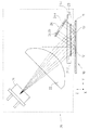
図1は、リニア式照射測定システムとして構成されたこの発明による位置測定装置の実施例の基本的な走査光路を示している。位置測定装置は、測定方向xに延びている測定尺10ならびに測定尺10と向かい合って測定方向xに動く走査装置20から成る。測定方向xは、図1では、図面に垂直の方向である。測定尺10と走査装置20は、例えば互いに位置を決められるように相互に動く機械部品で結合されている。例えば数値制御工作機械の装置や部品を考えると、この場合、この発明による位置測定装置から生成される信号は、ここには描かれていない工作機械制御装置により再加工される。
【0021】
この実施構成において、この発明による位置制御装置の測定尺10には、測定尺支持盤上に配置され、絶対位置特定のため走査装置によって走査される二つのトラック12、13がある。両トラック12、13は、測定方向xに延び、ここに描かれた位置測定装置の照射例においては、それぞれ異なる反射特性を持った分割領域の連続、すなわち反射率の高い分割領域と反射率の低い分割領域から構成されている。
【0022】
ここで述べている実施例の両トラック12,13の構成は、図2のaの測定尺の平面図において確認できる。第一トラック13(以下、絶対トラック13と言う)は、ここの例では、擬似ランダム符号の形の絶対符号として表されている。擬似ランダム符号は、それぞれ測定方向xに同じ幅を持つ反射率の高い分割領域と反射率の低い分割領域13.1、13.2の非周期的な連続から構成されている。周知の技術、方法においては、絶対トラック13の走査により粗い絶対位置信号ABSが走査信号として生成されるが、その解像度は望んでいるような高精度の位置測定にはまだ不十分である。もちろん、別の方法として、絶対トラック13に、例えばブロック符号やマンチェスター符号などのようなシリアル符号を使うこともできる。さらに、絶対トラックを、同様に周知の技術、方法において粗い絶対位置信号ABSの生成のために利用することができる一つあるいは複数の参照記号の絶対符号として表すことも可能である。
【0023】
第二トラック12(以下、増分トラック12と言う)は、絶対トラック13のすぐ近くに平行に配置されている。増分トラック12は、絶対トラック13と同様に測定方向xに延びている。増分トラック12は、測定尺10と走査装置20の相対位置を特定するために使われる、より高い解像度の、周期的な増分信号INCF 、INCG1、INCG2の形の絶対信号を生成するために利用される。これらまとまった三つの相異なる増分信号INCF 、INCG1、INCG2は、それぞれ細かい増分信号INCF 、第一粗い増分信号INCG1、第二粗い増分信号INCG2である。相異なる増分信号INCF 、INCG1、INCG2は、相互に動く部分の絶対位置を特定するために、絶対トラック13の絶対位置信号ABSと適当な技術と方法で組み合わされる。これにより、測定システムにおいては既に、後述の評価装置、例えば工作機械の数値制御装置においては初めて、これらの相異なる走査信号からそれぞれの絶対位置の特定が実現される。
【0024】
この例では、増分信号INCF 、INCG1、INCG2は、増分トラック12の走査による走査信号として生成される。細かい増分信号INCF は、信号周期SPF を有し、第一および第二粗い増分信号INCG1、INCG2は、それぞれ同じ信号周期SPG を示す。一般には、信号周期SPF とSPG は、明らかに互いに異なっている。
【0025】
走査される増分トラック12は、二つの相異なる分割周期TPF 、TPG を示し、この実施例においては周期的に連続した第一および第二ブロックB1、B2から構成される。増分トラック12の両分割周期TPF 、TPG の粗い方に対応する分割周期TPG は、二つの連続したブロックB1、B2の幅の合計で定義される。この実施構成においては、両ブロックB1、B2の幅は、同じになるように選択されている。特に、幅の合計で定義される粗い分割周期TPG は、走査にとって重要である。しかし、増分トラック12の走査技術に応じて、ブロックB1、B2を場合によっては様々な広さで構成することもできる。
【0026】
第一ブロックB1は、低い反射率で構成され、第二ブロックB2は、更に周期的に連続した低い反射率と高い反射率の光学特性を持った分割領域12.1、12.2から構成される。第二ブロックB2の部分拡大図が、図2のbに示されている。図2のbから分かるように、第二ブロックB2の分割領域12.1、12.2は、その長軸が測定尺平面においてy方向に延びている、つまり測定方向xに垂直の方向に向いている細い長方形の領域として構成されている。第二ブロックB2の相異なる分割領域12.1、12.2は、それぞれ同じ大きさで構成されている。同様に図2のbに詳しく示されているように、第一ブロックB1の二つの連続した分割領域12.1、12.2の広さの合計に対して、増分トラック12の細かい分割周期TPF が定義されている。
【0027】
この発明による位置測定装置の実施例の構成において、増分トラック12の細かい分割周期TPF は、増分トラック12の粗い分割周期TPG の8分の1、すなわちTPG =160μm、TPF =20μmになっている。
【0028】
基本的には、増分トラック12の粗い分割周期TPG は、細かい分割周期TPF の整数倍として選択されるべきである。連続したブロックB2が細かい分割周期TPF の連続した増分部分に対応することのみが保証される。したがって、特に、細かい分割周期TPF の増分部分が低い反射率のブロックB1によって中断される場合においても、全測定長にわたって常に低い反射率の分割領域12.1と高い反射率の分割領域12.2が交互に生成されることが保証されなければならない。ブロックB2の縁の低い反射率の分割領域12.1の次に、測定方向に対して直ぐ隣のブロックB2の中の高い反射率の分割領域12.2が続くなどである。図2のaの増分トラック12の図が、その他の点は詳細ではないが、このことを示している。
【0029】
この実施例においては、さらに絶対トラック13の擬似ランダム符号のビット幅を増分部分12の粗い分割周期TPG に合わせている。これは、絶対トラック13の分割領域13.1、13.2の幅が増分トラック12の分割周期TPG と測定方向xに同じになるように選択されていることを意味する。
【0030】
測定尺10のこの実施例に換えて、両トラック12、13の相異なる分割領域を他の光学特性で、つまり例えば高い反射率の分割領域と低い反射率の分割領域を入れ替えて、測定尺支持盤11上に構成することは、当然可能である。
【0031】
さらに、いろいろな信号周期の三つ以上の増分信号を得るように増分トラックを構成することも当然考えられる。
【0032】
さらに図1に模式的に描かれた走査装置20は、光源21、例えばLED、光コリメーター22、走査板23、ならびに相異なる走査信号を捕捉するための検出器24から成る。
【0033】
増分信号INCF 、INCG1、INCG2の生成のための走査光路および絶対位置信号ABSは、以下に別々に説明する。
【0034】
この実施例では、増分信号INCF 、INCG1、INCG2の生成のために光源21から放出された光束は、光コリメーター22によりコリメーションされた後、走査板23に届く。走査板23の図は、図3の平面図に描かれている。増分信号INCF 、INCG1、INCG2の生成のための光束は、それに応じて増分信号INCF 、INCG1、INCG2が生成される走査板23の相異なる領域を通り抜ける。さらに、走査板23の相異なる領域は、それぞれバーニャストライプを生成する検出器平面の既定の領域にも組み込まれている。
【0035】
細かい増分信号INCF と第一粗い増分信号INCG1の生成に用いられる前の光束は、走査板23の参照符号23.1で示された透明な窓領域を通り抜ける。それに対して、第二粗い増分信号INCG2の生成に用いられる光束は、それぞれ走査構造23.2、23.3が配置された両領域を通り抜ける。走査構造23.2、23.3は、それぞれ測定方向xに周期的に構成された透過性と非透過性分割領域から成る。走査構造23.2、23.3の透過性の分割領域は、図3の平面図ではほぼひし形に構成されている。しかし、透過性の分割領域は、理想的には外の輪郭線が余弦形をしている。走査構造23.2、23.3に関する他の規格サイズの措置については、後の説明で提示されている。
【0036】
各光束は、走査構造23.2、23.3あるいは透明な窓領域23.1を通過した後、増分信号INCF 、INCG1、INCG2の生成のために測定尺10の増分トラック12上に当たり、そこから走査板23の方向に反射される。反射された光速は、検出器24の各増分信号−検出器配列24.1、24.2、24.3に当たる前に、走査板23の透明な窓領域23.4を通過する。検出器24の具体的な構成に関しては、図4の検出器平面の模式的に描かれた平面図に示されているので、図1では、増分信号−検出器配列24.1、24.2、24.3の内の一つだけが示されている。検出器24側には、図4から明らかなように、信号周期SPF の細かい増分信号INCF の生成と信号周期SPG の第一粗い増分信号INCG1の同時生成のために第一増分信号−検出器配列24.1が設けられている。さらに、走査装置20は、同様に信号周期SPG の第二粗い増分信号INCG2の生成のために、この発明による少なくとも一つの第二増分信号−検出器配列24.2、24.3を持つ。当然の結果として増分信号が一対づつ生成され、これらは互いに位相が90°シフトしている。検出器24の詳細な構成に関しては、後の図4の詳細な説明に示されている。
【0037】
この実施例で粗い絶対位置信号ABSの生成のために用いられる光束は、光コリメーター22によるコリメーション後、走査板23の透過性の窓領域23.4を通り抜けて、測定尺10の絶対トラック13上に届く。そこから、走査板23の方向への反射が起こり、そこで反射された光速が再び透明な窓領域23.4を通過し、検出器24の絶対位置信号−検出器配列24.4に当たる。この照射によって、その結果として周知の技術と方法により擬似ランダム符号のその時々に捕捉された部分の単一の図形あるいは影絵が絶対位置信号−検出器配列24.4上に出来る。
【0038】
検出器24の検出器平面の図は、図4に模式的に描かれている。ここには、測定方向xに連続的に配置された多数の光電検出エレメント単体から構成される絶対位置信号−検出器配列24.4が上部に見える。この実施例においては、隣接した検出エレメント二つづつが、絶対トラック13の擬似ランダム符号の1ビットの走査に使われる、つまり擬似ランダム符号のビット走査に使われる検出エレメントには二つのグループがある。もちろん、測定動作においてはビット毎には両検出エレメントの内の一つだけが読み出される。これは、図4で検出エレメントの上に模式的に大まかに示された切替エレメントSA−SNで分かり易く示されている。この実施例では、1ビット幅に組み込まれた二つの検出エレメントが、さらにこのような切替エレメントSA−SNに組み込まれている。これにより、両グループの検出エレメントのどちらが擬似ランダム符号の各ビット群の中央付近にあるかに従って、各検出エレメントの選択的な読み出しが行われる。測定動作において、この判別を行うために、粗い信号周期SPG に対応する増分信号INCG1が利用される。
【0039】
絶対位置信号−検出器配列24.4の検出エレメントにより生成された走査信号は、それぞれ論理レベルがHIGHとLOWの信号を出力するここには記載されていないトリガーエレメントに送られ、絶対位置を特定するために再処理される。有利には、トリガーエレメントは、検出器24の支持基板上に統合された形で同様に配置されている。さらに、一定の信号レベルを示すかあるいは周知の技術と方法では走査信号の信号レベルに従って変化する参照信号が、出力信号を生成するため、トリガーエレメントに付加される。トリガーエレメントの出力信号は、同じくここでは描かれていない信号処理装置に送られ、そこで生成された増分信号として再処理されて、目的とする粗い絶対位置を表す出力信号ABSが生成される。
【0040】
この実施例では増分トラックの走査ならびに信号周期SPF とSPG の増分信号INCF 、INCG1、INCG2の生成のために利用される両増分信号−検出器配列24.1、24.2a、24.2bが、図4にある検出器平面の作図の下の部分に見える。
【0041】
詳細には、中央の第一増分信号−検出器配列24.1は細かい増分信号INCF と第一粗い増分信号INCG1を生成するために利用される。これらの増分信号INCF 、INCG1の生成に関して、その他の点は既に言及したドイツ国特許出願第19962278.7号に、特にそこで提示されている二番目の実施例に記載されている。
【0042】
この実施例では、第二粗い増分信号INCG2を生成するために利用される第二増分信号−検出器配列24.2a、24.2bは、同じ、いわゆる構造を持った検出器配列あるいは検出エレメントアレーから成る全部で二つの分離した検出器24.2a、24.2bから構成される。この発明の範囲において、基本的には第二増分信号−検出器配列をこのような検出器ただ一つで構成することも可能である。
【0043】
ここに述べられている検出器24.2a、24.2bは、周知の技術と方法では、検出器24.2a、24.2bの内部にまとまって同じような構成で、測定方向xに互いに隣接して配置された多数の長方形の光電検出エレメント単体から成る。このような検出器24.2a、24.2bの検出エレメントは、それぞれ出力側において相互に接続され、位相の合った走査信号を供給する。ここに示された実施例の構成においては、各検出エレメントは両検出器24.2a、24.2bで相互に接続され、検出器24.2a、24.2b毎に全部で4つのそれぞれ位相が90°シフトした部分増分信号を出力する。図4では描かれていないが、これらは、二つの位相が90°シフトした粗い増分信号INCG2を生成するために周知の技術と方法で互いに相違した形で接続される。上記では、便宜上第二粗い増分信号INCG2についてのみ述べているが、以下の記述においても同様とする。
【0044】
検出器平面では、第二増分信号−検出器配列24.2a、24.2bの領域それぞれに周期的な縞模様ができ、これらは光源21から出た光束と増分トラック12および走査板23にそれぞれ配置された走査構造23.2、23.3との相互作用から生まれ、信号周期SPG の第二粗い増分信号INCG2の生成のために利用される。なお、指摘したいのは、走査板23の走査構造23.2、23.3の透明な領域は、測定方向に対して第二増分信号−検出器配列24.2a、24.2bの構造を持った検出器配列に組み込まれた検出エレメントの幅bDET よりもより小さい最大幅bASを示している点である。
【0045】
原則的には、第二粗い増分信号INCG2の生成は、結果的にはここで述べたドイツ国特許出願第19962278.7号の最初の実施例にある増分信号の生成に対応する。この信号生成技術の詳細については、この開示された印刷物に明確に提示されている。
【0046】
特に、例えば走査構造23.2、23.3に関する第二粗い増分信号INCG2の不要な信号成分をフィルターする措置がこの関連で提示されている。このようなフィルタリングに関して、この実施例では、振幅格子として構成された走査構造23.2、23.3がフィルター特性を持つものとしている。このため、よく知られたフィルタリング措置が採られており、例えば走査構造23.2、23.3の透明な分割領域は、英国公開特許第2116313号明細書に提示されているように、開口部が正弦形状に作られている。図3において、走査構造23.2、23.3のこの形は、大まかに描くためにその他は単に模式的に表されている。
【0047】
これに代わるものとして、不要な高調波成分のフィルタリングは、周知の技術と方法では走査構造23.2、23.3に対する適当なウェブシフトにより実現される。不要な信号成分のフィルタリングに関して、この発明の範囲では別の周知の措置が自由に利用できる。
【0048】
この発明による位置測定装置のここに述べた構成では、増分トラック12の走査によって信号周期SPF の細かい増分信号INCF と同じ信号周期SPG の二つの粗い増分信号INCG1、INCG2が得られる。これらの信号を絶対トラック13から得られた粗い絶対位置信号ABSと組み合わせると、周知の技術と方法により高い解像度の絶対位置の特定が実現できる。この発明の装置に関して、その時の絶対位置を正確に特定するために、別の走査信号を相互に適当に差引きあるいは組み合わせることができる。同様に下位の評価装置で絶対位置の特定に使っている別の走査信号を利用することもできる。
【0049】
この発明による措置は、異なる走査信号INCF 、INCG1、INCG2とABSとの差引きあるいは同期によって、時として起こる測定尺に対する走査装置の縦方向のズレにおいても結果に誤りがないようにしている。ここでは、縦方向のズレあるいは縦方向の傾斜とは、測定尺面内あるいは測定尺面に平行にあり、測定方向に対して垂直方向の軸のまわりの測定尺と走査装置の傾きと定義される。さらに説明するため、図5のaからdと図6を参照されたい。図5のaからdの左側で、測定尺10と走査装置20を正しく調整した場合を、結果として得られた二つの粗い増分信号INCG1、INCG2と絶対位置信号ABSとともに描かれている。右側では、時として起こる縦方向の傾斜がある場合が描かれている。
【0050】
位置測定装置の構成に基づくと、このような縦方向のズレがある場合には細かい増分信号INCF と第一粗い増分信号INCG1が同じ状況を示すと言える。一方、この発明による場合には、第二粗い増分信号INCG2と絶対位置信号ABSが時として起こる縦方向のズレによりかなり似通った状況を示すと言える。時として起こる縦方向のズレがある場合、縦方向のズレ角φに依存する位相シフトΔG1-G2 が二つの信号INCG1、INCG2間で発生するが、これは測定尺上の各検出器配列の高さの僅かな相対的な違いにより生じる。一つのトラックにより生成された二つの走査信号は、二つの粗い増分信号INCG1、INCG2の形では結果として異なった縦方向のズレの状況を示す。
【0051】
走査装置と測定尺が理想的に正しく調整されている場合、つまり特に縦方向のズレが無い場合があり、その場合同じ信号周期の二つの粗い増分信号INCG1、INCG2は位相が合っている。この場合が図5のaとbの両図の左側に描かれている。
【0052】
時として起こる縦方向のズレにより、図5のbおよびcの右側から明らかなように、二つの粗い増分信号INCG1、INCG2間に位相シフトΔG1-G2 、あるいは位相差が生じる。二つの粗い増分信号INCG1、INCG2間の位相シフトΔG1-G2 は、二つの粗い増分信号INCG1、INCG2の異なる生成過程、あるいは異なる走査光路により生じる。縦方向のズレがある場合に生成された第一粗い増分信号INCG1では、検出器平面に出来る縞模様が縦方向のズレ角に応じて移動し、誤った位置変動を示すので、位置特定を誤る結果となる。一方、第二粗い増分信号INCG2では、そのような縦方向のズレにより生成された検出器平面に出来る縞模様は、検出器上でほとんど動かない、つまりそのような縦方向のズレがある場合でも正しい位置を検出する。
【0053】
したがって、二つの粗い増分信号INCG1、INCG2間の位相シフトΔG1-G2 は、測定尺と走査装置間で時として起こる縦方向のズレの尺度として考えられ、巧く活用することができる。ここで述べた実施例において、位相シフトΔG1-G2 と縦方向のズレ角φの関係は、幾何学的に考察して、以下の関係式で表される。
【0054】
ΔG1-G2=( 2* φ* h1*2π)/SPG Gl .(1)
あるいは、
φ=(ΔG1-G2*SPG )/( 2* h1*2π) Gl .(1')
φ : 縦方向のズレ角/ラジアン
SPG : 粗い増分信号周期
h1 : 第二増分信号−検出器配列の測定尺からの高さ
これらの大きさの定義については、この発明による位置測定装置の模式的な部分図を表している図6に補足して示す。もちろん、他の走査配列では、位相差と縦方向のズレ角間に別の関係が生じる。
【0055】
時として起こる縦方向のズレ角φの縦方向のズレがある場合、第二増分信号−検出器配列INCG2と絶対位置信号ABS間には、僅かな位相差ΔG2-ABSが生じる。これは、以下のとおりとなる。
【0056】
ΔG2-ABS=(2* φ*(h1 −h2)* 2π)/SPG Gl .(2)
図6の作図に対応して、h2 は、絶対位置信号−検出器配列24.4の測定尺10からの高さを表す。二つの長さh1 とh2 には差があるので、Gl .(2)から明らかなとおり縦方向のズレがある場合に僅かな位相差ΔG2-ABSが生じる。
【0057】
そのほか、時として起こる縦方向のズレがある場合の絶対位置信号ABSの状況は、図5のdに示されている。そこから分かるように、対応する走査光路により生成された絶対位置信号ABSも縦方向のズレでシフトするが、第二粗い増分信号INCG2との違いはほんの僅かである。絶対位置信号ABSの第二粗い増分信号INCG2との相対位置は、縦方向のズレがある場合においても一定の範囲内で変わらない。
【0058】
絶対位置の特定に必要な粗い増分信号INCG1あるいはINCG2と絶対位置信号ABSを同期させる場合には、これら信号間の位相シフトが許容最大値を超えないようにしなければならない。それだけで、絶対位置を正しく特定することができる。これは、またこの発明により二つの粗い増分信号INCG1、INCG2間の位相差ΔG1-G2 が許容最大位相差ΔG1-G2,max を超えないように監視することによって達成することができる。この実施例では、許容最大位相差ΔG1-G2 ,maxは、粗い増分信号の信号周期の半分、つまりΔG1-G2,max = SPG /2である。
【0059】
例えば位置測定装置の組み立てなどで、縦方向のズレに対する感度が異なる場合での二つの粗い増分信号INCG1、INCG2の位相差を定常的に監視することから、必要ある場合には絶対位置信号ABSと正しく同期するための許容最大位相シフトを超えているかどうかを判別できるようになる。ここで述べた時として起こる縦方向のズレがある場合においても正しい絶対位置を特定することができると言える。
【0060】
位相差ΔG1-G2 の適切な監視と特定は、時として起こる縦方向のズレを捕捉するため、一つのトラックから生成された相異なる縦方向のズレによる挙動を示す二つの走査信号を互いに比較する位置測定装置に組み込まれた比較器で実施することができる。このような比較器は、位置測定装置の側でも、位置測定装置に後続する評価装置の側でも構成することができる。許容できる最大の縦方向のズレを超える場合には、比較結果をもとに測定尺と走査装置の空間的な正しい調整が行われる。許容できる最大の縦方向のズレを超過した場合には、光と音による警報が発せられる。
【0061】
例えば組み立て時には、監視により実際に算出された位相差ΔG1-G2 は適当な表示器上に直接的な画像表示の形で表される。また、別の構成として、絶えず自動的に比較を行い、誤りがあった場合、つまり例えばΔG1-G2 >ΔG1-G2,max の場合だけ警報を発することも想定することができる。同様に実際の測定動作においてもこの位相差を監視し、誤りがあった場合に適当な警報を発することもできる。
【0062】
当然、ここで述べた実施例以外にも、この発明の範囲における別の実施構成が存在する。
【図面の簡単な説明】
【図1】 この発明による位置測定装置の実施例における走査光路の模式図、
【図2】 図1における測定尺の平面図、
【図3】 図1における位置測定装置の走査板上の平面図、
【図4】 図1における走査装置の検出器平面の図、
【図5】 この発明による位置測定装置における時に起こる走査装置の縦方向のズレがある場合の関連説明図、
【図6】 この発明による位置測定装置における幾何的サイズの説明のための部分模式図。
【符号の説明】
10 測定尺
11 測定尺支持盤
12 第二トラック(増分トラック)
12.1 低い反射率の分割領域
12.2 高い反射率の分割領域
13 第一トラック(絶対トラック)
20 走査装置
21 光源
22 光コリメーター
23 走査板
23.1 透明な窓領域
23.2 走査構造
23.3 走査構造
23.4 窓領域
24 検出器
24.1 第一増分信号−検出器配列
24.2 第二増分信号−検出器配列
24.3 第二増分信号−検出器配列
24.4 絶対位置信号−検出器配列
φ 縦方向のズレ角
ΔG1-G2 位相シフト(位相差)
bAS 走査構造(23.2,23.3)の最大幅
bDET 検出エレメントの幅
h1 第二増分信号−検出器配列の測定尺からの高さ
h2 絶対位置信号−検出器配列の測定尺10からの高さ
ABS 絶対位置信号(第二走査信号)
B1 第一ブロック
B2 第二ブロック
INCG1 第一粗い増分信号
INCG2 第二粗い増分信号
SA、SN 切替エレメント
SPF 細かい信号周期
SPG 粗い信号周期
TPF 細かい分割周期
TPG 粗い分割周期[0001]
BACKGROUND OF THE INVENTION
The present invention relates to a position measuring apparatus particularly suitable for specifying the absolute positions of two mutually moving objects. The present invention further relates to a method of operating the position measuring device.
[0002]
[Prior art]
A well-known type of position measuring device with respect to absolute position determination is an incremental track extending in the measuring direction on the surface of the measuring scale to be scanned and parallel to this, for example represented by a serial absolute sign. Have an absolute track. A position measuring device configured in accordance with this is presented, for example, in DE 19505176. For accurate positioning, the scanning signals related to the positions output from both tracks must be synchronized with each other. This is particularly important when each position analysis is heavily loaded and these signals are clearly different. When a thin metal belt is used on the measurement scale surface, a new problem arises because parallel adjustment in the measurement direction is not always optimal. In particular, a measurement error occurs when the measurement rule is twisted around an axis perpendicular to the measurement rule surface.
[0003]
In order to solve this problem, the Applicant presents in German Patent Application No. 19962278.7 that a suitable incremental track scan provides a resolution capable of distinguishing at least two incremental signals. For this purpose, in addition to appropriately configuring the incremental track to be scanned, it is necessary to appropriately adjust each detector array of the scanning device. In the above patent application, two suitable detector configurations are presented for this purpose, which solves the aforementioned problems caused by the twisting of the scanning device or the measuring rule about an axis perpendicular to the measuring rule, which sometimes occurs. can do.
[0004]
During the measurement operation, in addition to undesirable twisting around this axis, there is further vertical displacement of the scanning device or measurement scale around the measurement scale surface or parallel to the measurement scale surface and perpendicular to the measurement direction. May occur. Such vertical misalignment can also be detected as an error by synchronizing the scan signals of different position analysis, particularly when the scan signals of different tracks exhibit various behaviors due to the vertical misalignment.
[0005]
[Problems to be solved by the invention]
Therefore, it is an object of the present invention to present a position measurement device that always ensures reliable position specification. Furthermore, an operation method of such a position measuring device is presented.
[0006]
[Means for Solving the Problems]
This problem is solved by a position measuring device having the features of
[0007]
An advantageous embodiment of the position measuring device according to the invention is realized by the measures described in the dependent claims.
[0008]
Furthermore, this problem is solved by the operation method of the position measuring apparatus having the features of
[0009]
Advantageous implementations of the method according to the invention are realized by the measures described in the dependent claims.
[0010]
DETAILED DESCRIPTION OF THE INVENTION
According to the present invention, in addition to the first and second scanning signals generated from the first and second tracks, it differs from the other scanning signals generated from one of the two scanning tracks on the measuring scale. It has already been proposed that a third scanning signal can be generated that exhibits behavior due to vertical misalignment. For example, the third scanning signal shows the behavior due to the vertical shift similar to the scanning signal of another track. By observing the scanning signal obtained from the same track and showing the behavior due to different vertical deviations using a comparator incorporated in the position measuring device, for example, the behavior due to the vertical deviation of the system can be observed, Can be adjusted.
[0011]
In a preferred embodiment, the position measuring device according to the invention has a first track arranged as an incremental track on the measuring scale surface and an absolute track arranged parallel to it as a second track. On the surface of the scanning device which moves relative to the measuring scale, there are two incremental signal detector arrays as well as one absolute position signal detector array. Using the incremental signal detector array, first and second coarse incremental signals of the same coarse identification signal period are generated as scanning signals. Using the absolute position signal detector array, an absolute position signal is generated from scanning the absolute track. The two coarse incremental signals generated are different in that they each exhibit different vertical misalignment behavior. This is because the scanning signals generated by the different scanning optical paths sometimes have vertical displacements, i.e. when the scanning device and measuring scale are tilted around an axis extending perpendicular to the measuring direction within the measuring scale surface, for example. , Which means different behavior. For this reason, one coarse incremental signal is not affected, for example another coarse incremental signal is affected so that it no longer indicates the correct position.
[0012]
The third scanning signal generated in the form of a second coarse incremental signal according to the invention is, for example, when the scanning device and the measuring rule are tilted about an axis extending perpendicular to the measuring direction in the measuring rule plane. It shows the same behavior as the second scanning signal, that is, the absolute position signal. As a result, these two scanning signals can be synchronized without error even in such a case.
[0013]
Therefore, in a preferential implementation, the position measuring device according to the invention is resistant to twisting movements about an axis perpendicular to the measuring scale and also to vertical displacement. In any case, it is guaranteed that an accurate absolute position can be identified from the generated scanning signal.
[0014]
Furthermore, it has proven to be advantageous that both scanning signals exhibiting behavior due to different longitudinal shifts, i.e., for example by comparing their generated coarse incremental signals, in particular by measuring their phase difference, are no longer measured, for example. It is also possible to derive the inclination of the scanning device around the axis extending perpendicularly to the measuring direction in the scale surface and the vertical deviation of the measuring scale. This information can also be used for other purposes, such as precise adjustment of the scanning device during assembly.
[0015]
There are a range of possibilities for track configuration. The absolute code of the absolute track can be configured, for example, in the form of one or more reference symbols.
[0016]
The position measuring device according to the present invention can obviously be configured as both a linear position measuring device and a rotary position measuring device.
[0017]
Basically, the basis of this invention is that a plurality of tracks are scanned on a measuring scale, and the scanning signals generated from these different tracks show different behavior when there is an occasional vertical tilt. This principle can be applied to all position measuring devices. In addition, configuring each scanning device means deriving two scanning signals that exhibit different behaviors depending on the inclination in the vertical direction by appropriately scanning one of the tracks. The respective phase shifts between the two scanning signals indicate the degree of vertical inclination that actually exists, and can be monitored or adjusted in the measurement process.
[0018]
【Example】
Further advantages and details of the present invention will become apparent from the description of the embodiments based on the accompanying drawings described below.
[0019]
An embodiment of the position measuring apparatus according to the present invention will be described as follows with reference to FIGS. Here, it relates to a device for specifying the absolute position.
[0020]
FIG. 1 shows the basic scanning light path of an embodiment of the position measuring device according to the invention configured as a linear irradiation measuring system. The position measuring device comprises a
[0021]
In this embodiment, the measuring
[0022]
The configuration of the
[0023]
The second track 12 (hereinafter referred to as the incremental track 12) is arranged in parallel in the immediate vicinity of the
[0024]
In this example, the incremental signal INCF, INCG1, INCG2Is generated as a scanning signal by scanning the
[0025]
The
[0026]
The first block B1 is configured with a low reflectance, and the second block B2 is further configured with divided regions 12.1, 12.2 having optical characteristics of a continuous low reflectance and a high reflectance. The A partially enlarged view of the second block B2 is shown in FIG. As can be seen from FIG. 2b, the divided areas 12.1, 12.2 of the second block B2 have their long axes extending in the y direction on the measuring scale plane, that is, in the direction perpendicular to the measuring direction x. It is configured as a thin rectangular area. Different divided areas 12.1, 12.2 of the second block B2 are configured to have the same size. Similarly, as shown in detail in FIG. 2b, the fine division period TP of the
[0027]
In the configuration of the embodiment of the position measuring device according to the present invention, the fine division period TP of the
[0028]
Basically, the coarse division period TP of the
[0029]
In this embodiment, the bit width of the pseudo random code of the
[0030]
In place of this embodiment of the
[0031]
Furthermore, it is naturally conceivable to configure the incremental track so as to obtain three or more incremental signals of various signal periods.
[0032]
Furthermore, the
[0033]
Increment signal INCF, INCG1, INCG2The scanning optical path and the absolute position signal ABS for the generation of are described separately below.
[0034]
In this embodiment, the incremental signal INCF, INCG1, INCG2The light beam emitted from the
[0035]
Fine incremental signal INCFAnd the first coarse increment signal INCG1The light flux before being used for generating the light passes through the transparent window region indicated by reference numeral 23.1 of the
[0036]
Each light beam passes through the scanning structure 23.2, 23.3 or the transparent window region 23.1 and is then incremented by the INC signal.F, INCG1, INCG2Is generated on the
[0037]
In this embodiment, the light beam used for generation of the coarse absolute position signal ABS passes through the transparent window region 23.4 of the
[0038]
A view of the detector plane of
[0039]
Absolute position signal-Scan signals generated by the detector elements of detector array 24.4 are sent to trigger elements not described here that output signals of logic levels HIGH and LOW, respectively, to identify the absolute position. To be reprocessed. Advantageously, the trigger elements are likewise arranged in an integrated manner on the support substrate of the
[0040]
In this embodiment, incremental track scanning and signal period SP are used.FAnd SPGIncremental signal INCF, INCG1, INCG2Both incremental signal-detector arrays 24.1, 24.2a, 24.2b utilized for the generation of are visible in the lower part of the detector plane plot in FIG.
[0041]
Specifically, the central first incremental signal-detector array 24.1 is a fine incremental signal INC.FAnd the first coarse increment signal INCG1Is used to generate These incremental signals INCF, INCG1The other aspects of the production of are described in the already mentioned German patent application No. 19962278.7, particularly in the second embodiment presented therein.
[0042]
In this embodiment, the second coarse incremental signal INCG2The second incremental signal-detector array 24.2a, 24.2b used to generate the same is a detector array or detector element array with the same so-called structure, in total two
[0043]
The detectors 24.2a and 24.2b described here are similar in configuration to the inside of the detectors 24.2a and 24.2b and are adjacent to each other in the measurement direction x according to known techniques and methods. It is composed of a large number of rectangular photoelectric detection elements arranged in the same manner. The detection elements of the detectors 24.2a and 24.2b are connected to each other on the output side, and supply scanning signals in phase with each other. In the configuration of the embodiment shown here, the detection elements are connected to each other by both detectors 24.2a, 24.2b, and there are a total of four phases for each detector 24.2a, 24.2b. A partial increment signal shifted by 90 ° is output. Although not depicted in FIG. 4, these are coarse incremental signals INC with two phases shifted by 90 °.G2Are connected in different ways by known techniques and methods. In the above, for convenience, the second coarse increment signal INCG2The same applies to the following description.
[0044]
In the detector plane, a periodic striped pattern is created in each of the regions of the second incremental signal-detector arrays 24.2a, 24.2b, which are respectively emitted from the
[0045]
In principle, the second coarse incremental signal INCG2As a result corresponds to the generation of the incremental signal in the first embodiment of the German patent application 19962278.7 described here. The details of this signal generation technique are clearly presented in the disclosed printed matter.
[0046]
In particular, the second coarse incremental signal INC, for example with respect to the scanning structures 23.2, 23.3.G2Measures to filter out unwanted signal components are presented in this context. With respect to such filtering, in this embodiment, the scanning structures 23.2 and 23.3 configured as amplitude gratings are assumed to have filter characteristics. For this reason, well-known filtering measures have been taken, for example, the transparent divided areas of the scanning structures 23.2, 23.3 have openings as shown in GB-A-2163313. Is made sinusoidal. In FIG. 3, this shape of the scanning structure 23.2, 23.3 is only schematically represented for the sake of rough drawing.
[0047]
As an alternative, the filtering of unwanted harmonic components is achieved by a suitable web shift with respect to the scanning structures 23.2, 23.3 in known techniques and methods. Regarding the filtering of unwanted signal components, other known measures are freely available within the scope of the invention.
[0048]
In the described arrangement of the position measuring device according to the invention, the signal period SP is obtained by scanning the incremental track 12.FIncremental signal INCFSame signal period SPGTwo coarse incremental signals INCG1, INCG2Is obtained. When these signals are combined with the coarse absolute position signal ABS obtained from the
[0049]
The measure according to the invention is based on different scanning signals INCF, INCG1, INCG2By subtracting or synchronizing between ABS and ABS, there is no error in the result even in the vertical displacement of the scanning device with respect to the measuring scale that sometimes occurs. Here, the vertical displacement or the vertical inclination is defined as the inclination of the measuring scale and the scanning device around the axis perpendicular to the measuring direction in the measuring scale plane or parallel to the measuring scale plane. The For further explanation, refer to FIGS. 5a to 5d and FIG. On the left side of FIGS. 5a to 5d, when the measuring
[0050]
Based on the configuration of the position measuring device, if there is such a vertical shift, a fine incremental signal INCFAnd the first coarse increment signal INCG1Can be said to show the same situation. On the other hand, according to the present invention, the second coarse incremental signal INCG2It can be said that the absolute position signal ABS shows a situation that is quite similar due to the vertical deviation that sometimes occurs. If there is a vertical shift that sometimes occurs, a phase shift Δ that depends on the vertical shift angle φG1-G2Is the two signals INCG1, INCG2This occurs due to a slight relative difference in the height of each detector array on the measuring scale. Two scanning signals generated by one track are two coarse incremental signals INC.G1, INCG2In the form of, as a result, different vertical misalignments are shown.
[0051]
If the scanning device and the measuring scale are ideally adjusted correctly, i.e. in particular there may be no vertical shift, in which case two coarse incremental signals INC with the same signal periodG1, INCG2Are in phase. This case is depicted on the left side of both FIGS.
[0052]
Due to the occasional vertical misalignment, two coarse incremental signals INC are evident, as is apparent from the right side of FIGS.G1, INCG2Phase shift betweenG1-G2Or a phase difference occurs. Two coarse incremental signals INCG1, INCG2Phase shift betweenG1-G2Are two coarse incremental signals INCG1, INCG2Caused by different generation processes or different scanning light paths. First coarse incremental signal INC generated when there is a vertical misalignmentG1Then, the striped pattern formed on the detector plane moves in accordance with the vertical deviation angle, and shows an incorrect position variation, resulting in erroneous position specification. Meanwhile, the second coarse increment signal INCG2Then, the stripe pattern formed on the detector plane generated by such a vertical shift hardly moves on the detector, that is, the correct position is detected even when there is such a vertical shift.
[0053]
Thus, the two coarse incremental signals INCG1, INCG2Phase shift betweenG1-G2Is considered as a measure of the vertical misalignment that sometimes occurs between the measuring scale and the scanning device, and can be used skillfully. In the embodiment described here, the phase shift ΔG1-G2The relationship between the vertical displacement angle φ and the vertical displacement angle φ is expressed by the following relational expression, considering geometrically.
[0054]
ΔG1-G2= (2 * φ * h1* 2π) / SPG Gl. (1)
Or
φ = (ΔG1-G2* SPG) / (2 * h1* 2π) Gl. (1 ')
φ : Vertical displacement angle / radian
SPG : Coarse incremental signal period
h1 : Second incremental signal-height of detector array from measuring scale
The definitions of these sizes are shown in addition to FIG. 6 showing a schematic partial view of the position measuring device according to the present invention. Of course, in other scanning arrangements, another relationship occurs between the phase difference and the vertical shift angle.
[0055]
If there is a vertical shift of the vertical shift angle φ that sometimes occurs, the second incremental signal-detector array INCG2And the absolute position signal ABS have a slight phase difference ΔG2-ABSOccurs. This is as follows.
[0056]
ΔG2-ABS= (2 * φ * (h1-H2) * 2π) / SPG Gl. (2)
Corresponding to the drawing in FIG.2Represents the height of the absolute position signal-detector array 24.4 from the measuring
[0057]
In addition, the situation of the absolute position signal ABS when there is a vertical shift that sometimes occurs is shown in FIG. As can be seen, the absolute position signal ABS generated by the corresponding scanning optical path also shifts with a vertical shift, but the second coarse incremental signal INCG2The difference is very small. Second coarse increment signal INC of absolute position signal ABSG2The relative position does not change within a certain range even when there is a vertical shift.
[0058]
Coarse incremental signal INC required to determine absolute positionG1Or INCG2When the absolute position signal ABS is synchronized, the phase shift between these signals must not exceed an allowable maximum value. Only then can the absolute position be correctly identified. This is also due to the invention that two coarse incremental signals INCG1, INCG2Phase difference betweenG1-G2Is the maximum allowable phase difference ΔG1-G2, maxCan be achieved by monitoring so as not to exceed. In this embodiment, the maximum allowable phase difference ΔG1-G2, max is half the signal period of the coarse incremental signal, ie ΔG1-G2, max= SPG/ 2.
[0059]
For example, two coarse incremental signals INC when the sensitivity to vertical deviation is different due to assembly of a position measuring device or the like.G1, INCG2Therefore, it is possible to determine whether or not the allowable maximum phase shift for correctly synchronizing with the absolute position signal ABS is exceeded if necessary. It can be said that the correct absolute position can be specified even when there is a vertical shift that occurs as described here.
[0060]
Phase difference ΔG1-G2Appropriate monitoring and identification is incorporated into a position measurement device that compares two scanning signals generated from one track and exhibiting behavior due to different vertical displacements, in order to capture occasional vertical displacements. It can be implemented with a comparator. Such a comparator can be constructed either on the position measuring device side or on the evaluation device side following the position measuring device. If the maximum allowable vertical deviation is exceeded, the spatial adjustment of the measuring scale and the scanning device is performed based on the comparison result. If the maximum allowable vertical misalignment is exceeded, a light and sound warning is issued.
[0061]
For example, during assembly, the phase difference Δ actually calculated by monitoringG1-G2Is represented in the form of a direct image display on a suitable display. As another configuration, the comparison is always performed automatically, and if there is an error, for example, ΔG1-G2> ΔG1-G2, maxIt can be assumed that an alarm is issued only in the case of. Similarly, in the actual measurement operation, this phase difference can be monitored, and an appropriate alarm can be issued if there is an error.
[0062]
Naturally, there are other implementation configurations within the scope of the present invention in addition to the embodiments described herein.
[Brief description of the drawings]
FIG. 1 is a schematic diagram of a scanning optical path in an embodiment of a position measuring device according to the present invention;
FIG. 2 is a plan view of the measuring rule in FIG.
FIG. 3 is a plan view on a scanning plate of the position measuring apparatus in FIG.
4 is a diagram of a detector plane of the scanning device in FIG.
FIG. 5 is a related explanatory diagram in the case where there is a vertical displacement of the scanning device that sometimes occurs in the position measuring device according to the invention;
FIG. 6 is a partial schematic diagram for explaining a geometric size in the position measuring apparatus according to the present invention.
[Explanation of symbols]
10 Measuring scale
11 Measuring scale support board
12 Second track (incremental track)
12.1 Low reflectivity split area
12.2 Divided areas with high reflectivity
13 First track (absolute track)
20 Scanning device
21 Light source
22 Optical collimator
23 Scanning plate
23.1 Transparent window area
23.2 Scanning structure
23.3 Scanning structure
23.4 Window area
24 Detector
24.1 First incremental signal-detector arrangement
24.2 Second incremental signal-detector arrangement
24.3 Second incremental signal-detector arrangement
24.4 Absolute position signal-detector array
φ Vertical displacement angle
ΔG1-G2 Phase shift (phase difference)
bAS Maximum width of scanning structure (23.2, 23.3)
bDET Detecting element width
h1 Second incremental signal-the height of the detector array from the measuring scale
h2 Absolute position signal-height of detector array from measuring
ABS absolute position signal (second scanning signal)
B1 first block
B2 second block
INCG1 1st coarse incremental signal
INCG2 Second coarse incremental signal
SA, SN switching element
SPF Fine signal period
SPG Coarse signal period
TPF Fine division cycle
TPG Coarse division period
Claims (10)
走査装置(20)を用いて測定尺(10)を走査することによって、位置に対応した走査信号が生成され、 By scanning the measuring rule (10) using the scanning device (20), a scanning signal corresponding to the position is generated,
測定尺(10)上には、相異なる反射率を有する互いに並んだ分割領域を有する少なくとも一つの第一および第二トラック(12,13)が配置されており、第一トラック(13)として、測定方向(x)に延びる絶対符号形式の絶対トラック(13)が配置されるとともに、第二トラック(12)として、絶対トラック(13)と平行に測定方向(x)に延びる増分符号形式の増分トラック(12)が配置されており、 On the measuring scale (10), at least one first and second tracks (12, 13) having mutually divided divided areas having different reflectivities are arranged, and as the first track (13), An absolute code type absolute track (13) extending in the measurement direction (x) is arranged and an incremental code type increment extending in the measurement direction (x) parallel to the absolute track (13) as a second track (12) Track (12) is placed,
走査装置(20)は、光源(21)と、光コリメーター(22)と、走査板(23)と、検出器平面内に第一増分信号−検出器配列(24.1)、第二増分信号−検出器配列(24.2a,24.2b)及び絶対位置信号−検出器配列(24.4)が配置された検出器(24)とを備えており、第一増分信号−検出器配列(24.1)は、長い信号周期(SP The scanning device (20) comprises a light source (21), a light collimator (22), a scanning plate (23), a first incremental signal-detector array (24.1) in a detector plane, a second incremental. A first incremental signal-detector array comprising a signal-detector array (24.2a, 24.2b) and a detector (24) in which an absolute position signal-detector array (24.4) is arranged. (24.1) is a long signal period (SP G G )の粗い増分信号(INC) Coarse incremental signal (INC) G1G1 )形式の第一走査信号(INC) Format first scanning signal (INC) G1G1 )を生成するのに適しており、第二増分信号−検出器配列(24.2a,24.2b)は、第一走査信号(INC) And the second incremental signal-detector array (24.2a, 24.2b) is connected to the first scanning signal (INC). G1G1 )と同じ信号周期の長い信号周期(SP) With a long signal period (SP G G )の第二粗い増分信号(INC) Second coarse incremental signal (INC) G2G2 )形式の第三走査信号(INC) Format third scanning signal (INC) G2G2 )を生成するのに適しており、絶対位置信号−検出器配列(24.4)は、絶対位置信号(ABS)形式の第二走査信号(ABS)を生成するのに適しており、), And the absolute position signal-detector array (24.4) is suitable for generating a second scanning signal (ABS) in the form of an absolute position signal (ABS),
縦方向のズレが、測定尺(10)の面内又は測定尺(10)の面に対して平行に延びるとともに、測定方向(x)に対して垂直な方向を向いた軸の周りの測定尺(10)と走査装置(20)の傾きとして定義され、そのような縦方向のズレが起こった場合に、第三走査信号(INC A measurement rule around an axis whose longitudinal deviation extends in the plane of the measurement rule (10) or parallel to the surface of the measurement rule (10) and is oriented perpendicular to the measurement direction (x) (10) and the inclination of the scanning device (20). When such a vertical deviation occurs, the third scanning signal (INC G2G2 )と増分トラック(12)から生成される別の第一走査信号(INC) And another first scanning signal (INC) generated from the incremental track (12) G1G1 )が、そのような縦方向のズレに対して異なる作用を示し、その結果そのような縦方向のズレが起こった場合に、第三走査信号(INC) Have a different effect on such vertical displacement, and as a result, when such vertical displacement occurs, the third scanning signal (INC) G2G2 )を生成するための走査光路の長さが、別の走査信号(INC) To generate another scanning signal (INC). G1G1 )を生成するための走査光路の長さと異なり、走査信号(INCUnlike the length of the scanning optical path for generating the scanning signal (INC) G1G1 ,INC, INC G2G2 )間に位相差(Δ) Phase difference (Δ G1-G2 G1-G2 )が生じることとなり、) Will occur,
この場合、走査板(23)は、少なくとも一つの第一の透明な窓領域(23.1)と第二の透明な窓領域(23.4)とを備えており、光源(21)から放出された走査用の光束が、光コリメーター(22)によりコリメーションされた後、一部の光束が、第一の透明な窓領域(23.1)を通り抜けて、測定尺(10)の増分トラック(12)上に当たり、そこから走査板(23)の方向に反射されて、第二の透明な窓領域(23.4)を通過して、検出器(24)の第一増分信号−検出器配列(24.1)に当たり、一部の光束が、第二の透明な窓領域(23.4)を通り抜けて、測定尺(10)の絶対トラック(13)上に当たり、そこから走査板(23)の方向に反射されて、再び第二の透明な窓領域(23.4)を通過して、検出器(24)の絶対位置信号−検出器配列(24.4)に当たるように構成されており、 In this case, the scanning plate (23) comprises at least one first transparent window region (23.1) and a second transparent window region (23.4) and emits from the light source (21). After the collimated scanning light beam is collimated by the optical collimator (22), a part of the light beam passes through the first transparent window region (23.1), and the measuring track (10) incremental track. (12) first incremental signal-detector of detector (24), hitting on and reflected from there in the direction of the scanning plate (23) and passing through the second transparent window region (23.4) When hitting the array (24.1), a part of the light beam passes through the second transparent window region (23.4), hits the absolute track (13) of the measuring scale (10), and from there the scanning plate (23 ) And pass again through the second transparent window region (23.4) to detect Absolute position signal (24) - is configured to strike the detector array (24.4),
そして、走査板(23)は、更に、少なくとも一つの走査構造(23.2,23.3)を備えており、光源(21)から放出された走査用の光束が、光コリメーター(22)によりコリメーションされた後、一部の光束が、走査構造(23.2,23.3)を通り抜けて、測定尺(10)の増分トラック(12)上に当たり、そこから再び走査板(23)の方向に反射されて、第二の透明な窓領域(23.4)を通過して、検出器(24)の第二増分信号−検出器配列(24.2a,24.2b)に当たるように構成されている、 The scanning plate (23) further includes at least one scanning structure (23.2, 23.3), and the scanning light beam emitted from the light source (21) is reflected by the optical collimator (22). After collimation, a part of the light beam passes through the scanning structure (23.2, 23.3), hits the incremental track (12) of the measuring scale (10), and from there again the scanning plate (23) Configured to reflect in the direction and pass through the second transparent window region (23.4) and strike the second incremental signal-detector array (24.2a, 24.2b) of the detector (24). Being
位置測定装置。Position measuring device.
Applications Claiming Priority (2)
| Application Number | Priority Date | Filing Date | Title |
|---|---|---|---|
| DE10130938A DE10130938A1 (en) | 2001-06-27 | 2001-06-27 | Position measuring device and method for operating a position measuring device |
| DE10130938.4 | 2001-06-27 |
Publications (3)
| Publication Number | Publication Date |
|---|---|
| JP2003042810A JP2003042810A (en) | 2003-02-13 |
| JP2003042810A5 JP2003042810A5 (en) | 2005-08-25 |
| JP4233814B2 true JP4233814B2 (en) | 2009-03-04 |
Family
ID=7689603
Family Applications (1)
| Application Number | Title | Priority Date | Filing Date |
|---|---|---|---|
| JP2002177199A Expired - Fee Related JP4233814B2 (en) | 2001-06-27 | 2002-06-18 | Position measuring apparatus and operation method of position measuring apparatus |
Country Status (6)
| Country | Link |
|---|---|
| US (1) | US6914235B2 (en) |
| EP (1) | EP1271107B1 (en) |
| JP (1) | JP4233814B2 (en) |
| AT (1) | ATE440266T1 (en) |
| DE (2) | DE10130938A1 (en) |
| ES (1) | ES2329878T3 (en) |
Families Citing this family (18)
| Publication number | Priority date | Publication date | Assignee | Title |
|---|---|---|---|---|
| GB0413827D0 (en) | 2004-06-21 | 2004-07-21 | Renishaw Plc | Scale reading apparatus |
| GB0428165D0 (en) * | 2004-12-23 | 2005-01-26 | Renishaw Plc | Position measurement |
| DE102005015743B4 (en) * | 2005-04-06 | 2018-08-23 | Dr. Johannes Heidenhain Gmbh | Scanning unit for a position measuring device for optically scanning a material measure and position measuring device |
| JP4951885B2 (en) * | 2005-06-29 | 2012-06-13 | ミツミ電機株式会社 | Encoder device |
| DE102006029650B4 (en) * | 2006-06-28 | 2020-02-20 | Dr. Johannes Heidenhain Gmbh | Circuit arrangement and method for determining tilting errors on a position measuring device |
| US7943897B2 (en) * | 2007-06-20 | 2011-05-17 | Sharp Kabushiki Kaisha | Optical encoder and electronic equipment |
| DE102007033009A1 (en) | 2007-07-12 | 2009-01-15 | Dr. Johannes Heidenhain Gmbh | Method and device for transmitting signals from a position-measuring device to an evaluation unit |
| DE102007056612A1 (en) * | 2007-11-23 | 2009-05-28 | Dr. Johannes Heidenhain Gmbh | Optical position measuring device |
| GB0819767D0 (en) * | 2008-10-28 | 2008-12-03 | Renishaw Plc | Absolute encoder setup indication |
| JP4816988B1 (en) * | 2011-02-10 | 2011-11-16 | 株式会社安川電機 | Encoder, optical module and servo system |
| DE102011007459B4 (en) | 2011-04-15 | 2023-05-11 | Dr. Johannes Heidenhain Gmbh | Optical length measuring device |
| DE102012212767A1 (en) * | 2012-07-20 | 2014-01-23 | Dr. Johannes Heidenhain Gmbh | Position measuring device |
| EP3015828B1 (en) | 2014-10-30 | 2016-09-28 | Fagor, S. Coop. | Optoelectronic device and method thereof |
| CN106052724B (en) * | 2016-05-19 | 2019-01-25 | 深圳市越疆科技有限公司 | A kind of robot, rotary measurement device and method |
| JP6953772B2 (en) * | 2017-04-13 | 2021-10-27 | 株式会社ニコン | Error detection method, error detection program, error detection device, manufacturing method of encoder device, encoder device, drive device, stage device, and robot device |
| US10859363B2 (en) | 2017-09-27 | 2020-12-08 | Stanley Black & Decker, Inc. | Tape rule assembly with linear optical encoder for sensing human-readable graduations of length |
| JP7293660B2 (en) * | 2019-01-18 | 2023-06-20 | 株式会社ジェイテクト | Rotation angle detector |
| JP7210103B2 (en) * | 2019-01-28 | 2023-01-23 | 株式会社ミツトヨ | Encoder life detector |
Family Cites Families (12)
| Publication number | Priority date | Publication date | Assignee | Title |
|---|---|---|---|---|
| GB1174145A (en) * | 1967-08-04 | 1969-12-10 | British Aircraft Corp Ltd | Measuring Systems |
| GB2116313B (en) | 1982-02-25 | 1985-09-04 | Ferranti Plc | Sine wave generator for position encoder |
| DE3726678C1 (en) | 1987-08-11 | 1989-03-09 | Heidenhain Gmbh Dr Johannes | Incremental length or angle measuring device |
| EP0555507B1 (en) * | 1992-02-14 | 1995-01-11 | Dr. Johannes Heidenhain GmbH | Position measuring apparatus |
| CH690971A5 (en) | 1994-02-25 | 2001-03-15 | Hera Rotterdam Bv | Methods for measuring and exploitation of a shift of a scanning head with respect to a measuring scale and optical encoders for performing this method. |
| US6229140B1 (en) * | 1995-10-27 | 2001-05-08 | Canon Kabushiki Kaisha | Displacement information detection apparatus |
| JPH1033636A (en) | 1996-05-03 | 1998-02-10 | Yuyama Seisakusho:Kk | Medicine separately wrapping device, medicine bottle, and medicine testing method |
| DE19642200A1 (en) | 1996-10-12 | 1998-04-16 | Heidenhain Gmbh Dr Johannes | Control device and method for testing position-dependent scanning signals |
| DE19859670A1 (en) | 1998-12-23 | 2000-06-29 | Heidenhain Gmbh Dr Johannes | Readhead and method of making same |
| DE19908328A1 (en) * | 1999-02-26 | 2000-08-31 | Heidenhain Gmbh Dr Johannes | Optical position measurement equipment has scanning unit and measurement scale having at least two measurement divisions |
| DE19941318A1 (en) * | 1999-08-31 | 2001-03-15 | Heidenhain Gmbh Dr Johannes | Optical position measuring device |
| DE19962278A1 (en) | 1999-12-23 | 2001-08-02 | Heidenhain Gmbh Dr Johannes | Position measuring device |
-
2001
- 2001-06-27 DE DE10130938A patent/DE10130938A1/en not_active Withdrawn
-
2002
- 2002-06-10 EP EP02012780A patent/EP1271107B1/en not_active Expired - Lifetime
- 2002-06-10 ES ES02012780T patent/ES2329878T3/en not_active Expired - Lifetime
- 2002-06-10 AT AT02012780T patent/ATE440266T1/en not_active IP Right Cessation
- 2002-06-10 DE DE50213775T patent/DE50213775D1/en not_active Expired - Lifetime
- 2002-06-18 JP JP2002177199A patent/JP4233814B2/en not_active Expired - Fee Related
- 2002-06-26 US US10/180,916 patent/US6914235B2/en not_active Expired - Lifetime
Also Published As
| Publication number | Publication date |
|---|---|
| ATE440266T1 (en) | 2009-09-15 |
| ES2329878T3 (en) | 2009-12-02 |
| DE50213775D1 (en) | 2009-10-01 |
| EP1271107B1 (en) | 2009-08-19 |
| US20030016369A1 (en) | 2003-01-23 |
| EP1271107A1 (en) | 2003-01-02 |
| DE10130938A1 (en) | 2003-01-23 |
| US6914235B2 (en) | 2005-07-05 |
| JP2003042810A (en) | 2003-02-13 |
Similar Documents
| Publication | Publication Date | Title |
|---|---|---|
| JP4233814B2 (en) | Position measuring apparatus and operation method of position measuring apparatus | |
| JP4503822B2 (en) | Position measuring device | |
| JP5147367B2 (en) | Encoder | |
| JP5046523B2 (en) | Position measuring device | |
| US6476405B1 (en) | Measurement apparatus having a diffraction grating structure | |
| US7141780B2 (en) | Position determination system for determining the position of one relatively moveable part relative to another relatively movable part | |
| JP5710105B2 (en) | Optical position measuring device | |
| JP5128368B2 (en) | Scale and encoder for encoder | |
| ES2376656T3 (en) | POSITION METER DEVICE. | |
| CN110030924A (en) | Position-measurement device | |
| JP4303804B2 (en) | Optical position measuring device | |
| JP7222081B2 (en) | Linear and rotary multi-track absolute position encoder and method of using same | |
| US5606409A (en) | Laser ranging system calibration device | |
| JP7181808B2 (en) | Optical position measuring device | |
| CN100487382C (en) | Reflective optical encoder | |
| JP4746297B2 (en) | Optical position measuring device | |
| JP2000230803A (en) | Optical location measuring device | |
| JP4503803B2 (en) | Device for measuring position and calculating guidance error | |
| US9303981B2 (en) | Position-measuring device | |
| JP2005502036A (en) | Position measuring device and method for operating the position measuring device | |
| CN110418943A (en) | Encoder apparatus | |
| JP6873760B2 (en) | Position measuring device including an optical distance sensor and an optical distance sensor | |
| JP2022500646A (en) | measuring device | |
| JP4292569B2 (en) | Optical encoder | |
| JPH11118422A (en) | Dimension measuring device using moire fringe |
Legal Events
| Date | Code | Title | Description |
|---|---|---|---|
| A521 | Request for written amendment filed |
Free format text: JAPANESE INTERMEDIATE CODE: A523 Effective date: 20050216 |
|
| A621 | Written request for application examination |
Free format text: JAPANESE INTERMEDIATE CODE: A621 Effective date: 20050216 |
|
| A131 | Notification of reasons for refusal |
Free format text: JAPANESE INTERMEDIATE CODE: A131 Effective date: 20080805 |
|
| A521 | Request for written amendment filed |
Free format text: JAPANESE INTERMEDIATE CODE: A523 Effective date: 20081010 |
|
| TRDD | Decision of grant or rejection written | ||
| A01 | Written decision to grant a patent or to grant a registration (utility model) |
Free format text: JAPANESE INTERMEDIATE CODE: A01 Effective date: 20081125 |
|
| A01 | Written decision to grant a patent or to grant a registration (utility model) |
Free format text: JAPANESE INTERMEDIATE CODE: A01 |
|
| A61 | First payment of annual fees (during grant procedure) |
Free format text: JAPANESE INTERMEDIATE CODE: A61 Effective date: 20081210 |
|
| FPAY | Renewal fee payment (event date is renewal date of database) |
Free format text: PAYMENT UNTIL: 20111219 Year of fee payment: 3 |
|
| R150 | Certificate of patent or registration of utility model |
Ref document number: 4233814 Country of ref document: JP Free format text: JAPANESE INTERMEDIATE CODE: R150 Free format text: JAPANESE INTERMEDIATE CODE: R150 |
|
| FPAY | Renewal fee payment (event date is renewal date of database) |
Free format text: PAYMENT UNTIL: 20111219 Year of fee payment: 3 |
|
| FPAY | Renewal fee payment (event date is renewal date of database) |
Free format text: PAYMENT UNTIL: 20121219 Year of fee payment: 4 |
|
| R250 | Receipt of annual fees |
Free format text: JAPANESE INTERMEDIATE CODE: R250 |
|
| FPAY | Renewal fee payment (event date is renewal date of database) |
Free format text: PAYMENT UNTIL: 20121219 Year of fee payment: 4 |
|
| FPAY | Renewal fee payment (event date is renewal date of database) |
Free format text: PAYMENT UNTIL: 20131219 Year of fee payment: 5 |
|
| R250 | Receipt of annual fees |
Free format text: JAPANESE INTERMEDIATE CODE: R250 |
|
| R250 | Receipt of annual fees |
Free format text: JAPANESE INTERMEDIATE CODE: R250 |
|
| R250 | Receipt of annual fees |
Free format text: JAPANESE INTERMEDIATE CODE: R250 |
|
| R250 | Receipt of annual fees |
Free format text: JAPANESE INTERMEDIATE CODE: R250 |
|
| R250 | Receipt of annual fees |
Free format text: JAPANESE INTERMEDIATE CODE: R250 |
|
| R250 | Receipt of annual fees |
Free format text: JAPANESE INTERMEDIATE CODE: R250 |
|
| R250 | Receipt of annual fees |
Free format text: JAPANESE INTERMEDIATE CODE: R250 |
|
| R250 | Receipt of annual fees |
Free format text: JAPANESE INTERMEDIATE CODE: R250 |
|
| LAPS | Cancellation because of no payment of annual fees |