JP4232332B2 - Brush stand for electric floor polisher with tank - Google Patents

Brush stand for electric floor polisher with tank Download PDF

Info

Publication number
JP4232332B2
JP4232332B2 JP2000314464A JP2000314464A JP4232332B2 JP 4232332 B2 JP4232332 B2 JP 4232332B2 JP 2000314464 A JP2000314464 A JP 2000314464A JP 2000314464 A JP2000314464 A JP 2000314464A JP 4232332 B2 JP4232332 B2 JP 4232332B2
Authority
JP
Japan
Prior art keywords
flocking
base
rib
brush
detergent
Prior art date
Legal status (The legal status is an assumption and is not a legal conclusion. Google has not performed a legal analysis and makes no representation as to the accuracy of the status listed.)
Expired - Fee Related
Application number
JP2000314464A
Other languages
Japanese (ja)
Other versions
JP2002051836A5 (en
JP2002051836A (en
Inventor
末藏 岩田
Original Assignee
末藏 岩田
Priority date (The priority date is an assumption and is not a legal conclusion. Google has not performed a legal analysis and makes no representation as to the accuracy of the date listed.)
Filing date
Publication date
Application filed by 末藏 岩田 filed Critical 末藏 岩田
Priority to JP2000314464A priority Critical patent/JP4232332B2/en
Publication of JP2002051836A publication Critical patent/JP2002051836A/en
Publication of JP2002051836A5 publication Critical patent/JP2002051836A5/ja
Application granted granted Critical
Publication of JP4232332B2 publication Critical patent/JP4232332B2/en
Anticipated expiration legal-status Critical
Expired - Fee Related legal-status Critical Current

Links

Images

Description

【0001】
【発明の属する技術分野】
本発明は、ビルなどの床面清掃に用いるタンク付電動床磨機に取り付けて用いるブラシ台に関するものである。
【0002】
【従来の技術】
電動床磨機の上部に洗剤液入りタンクを取り付けて、洗剤液を滴下しながら床面を清掃する方法は従来から存在していたが、タンクの取り付け位置が高く、かつ、タンクが重いため重心が高くなり使いにくいのであまり普及しなかった。
その後、改良機種の登場で徐々に普及し始めたが、付随するブラシ台は樹脂或いはアルミ製基台の上面の内外方向間に複数のリブを設けることにより基台のねじれ防止の役割を科すと共に、リブに近接して小さな洗剤滴下孔を設けたものを用いていて、数十年来、全く進歩が見られなかった。
【0003】
【発明が解決しようとする課題】
近年開発されたタンク付高速電動床磨機に従来のブラシ台を用いる場合、上面の内外方向間に設けた複数のリブに洗剤液が強く当たって望まない方向に洗剤液が飛散し、肝心の洗剤滴下孔内には充分流れないという欠点が生じたが、耐力の関係で細長い大きな洗剤滴下孔を設けることも出来なかった。
【0004】
基台の補強上必要不可欠な肋材としてのリブであるが、位置を単に上面より下面に移設すると、リブが邪魔になってブラシ毛材の取り付けに甚だ不都合が生じると共に洗剤滴下孔の設定位置が困難であった。
【0005】
本発明は高速回転するブラシ台の基台上面に滴下する洗剤液の量に関係なく、全く洗剤液が飛散せず確実に洗剤滴下孔内にすべて流入し得るブラシ台及び研磨効果が高く、回転振動の少ない効率的なブラシ台の提供を目的とする。
【0006】
【課題を解決するための手段】
上記目的を達成するために本発明に係るタンク付電動床磨機用ブラシ台は次のようなものとした。すなわち、請求項1に係るタンク付電動床磨機用ブラシ台は、円板状の基台1の上面の外周寄りに環状リブ9を設けて下面には内方から外周へ向け間隔をあけて複数のリブ3を設け、各リブ3の間にちょうどはまる形状として下面に多数のブラシ毛材8を植毛した植毛板4を各リブ3の間にそれぞれ取り付け、細長いスリット状の洗剤滴下孔6の複数状をリブ3を設けた位置において内方から外周へ向け基台1に設けたものである。
請求項2に係るタンク付電動床磨機用ブラシ台は、円板状の基台1の上面の外周寄りに環状リブ9を設けて下面には内方から外周へ向け間隔をあけて複数のリブ3を設け、各リブ3の間にちょうどはまる形状として下面に多数のブラシ毛材8を植毛した植毛板4を各リブ3の間にそれぞれ取り付け、細長いスリット状の洗剤滴下孔6の複数状を内方から外周へ向け環状リブ9の内側に設けたものである。
請求項1・2に係るブラシ台をタンク付電動床磨機の下に取り付け、タンクから洗剤を流下させながらブラシ台を回転させ床磨きをするとき、基台1上に流下する洗剤は基台1の上面外周寄りに設けられた環状リブ9によって外周へ飛散することが防がれ、基台1に設けられた洗剤滴下孔6から流下していく。
【0007】
【発明の実施の形態】
請求項に係わるタンク付電動床磨機用ブラシ台は円板状の基台1の中央に、電動床磨機下部の回転体に取り付けるため、円形とした中央穴をあけ、上面のそのまわりには円形の凸部2を設け、さらに、外周寄りに外周に平行して、洗剤液の飛散を防ぐと共に基台1の歪み防止と補強を目的とする凸条を巡らし、環状リブ9としている。
以下、洗剤液は洗剤として記載する。基台1の上面及び下面については、各々その面を上から見た場合として説明する。基台1の下面において、内方から外周に向けて基台1の歪み防止と補強の目的も兼ねて、幅を広くしたリブ3を等間隔で複数、放射状に設けている。各リブ3の両外側の下端を切欠いて、後記する植毛板4を保持するための溝5をそれぞれ設け、リブ3の反対位置の基台1上面には洗剤滴下孔6を形成している。
【0008】
リブ3とリブ3の間にちょうどはまる外周形状とした扇形類似の植毛板4を複数用意するが、植毛板4の両側下端には、リブ3に設けた溝5にはまる突条7をそれぞれ設けていて、植毛板4の表面には研磨粒子を含有させた多数のブラシ毛材8を直立させて植毛している。
植毛板4をリブ3と、隣合うリブ3の間の外周端よりはめ込んだ後、植毛板4の内端付近において、基台1との間に木ねじ11をねじ込んで両者を固定している。固定する方法としては植毛板4の内端付近に接する基台1部分を高くして、両者の間に凹凸を設け、電車の連結器のように凹凸部の組み合わせや布製ファスナーのオス、メスを用いて固定するなど、どのような方法で固定してもよい。
【0009】
ブラシ毛材8は長い毛材の束を切断機を用いて一定の長さに切断するほか、長いブラシ毛材8の一本乃至数本をほぼ一定の長さになるようにジグザグに折り返して束ねたものを用いてもよい。従来広く用いられている円形の植毛穴13の中に、ブラシ毛材8の束の中央部を2つに折り返したのち、U字釘や細針金を挟んで取り付けるほか、どのような植毛法にも用いることができる。
ジグザグに形成し植毛したブラシ毛材8は、毛先の一本一本にループを形成し、使用するときループ部分は押し潰されて平均的に床面に接触する。そして、接床面積を拡げることにより研磨効果を大きく向上させる。同時にループ部分の圧力変形の繰り返しにより、クッションの役割を果すので回転振動が減殺され、作業者の疲労軽減に効果的である。
【0010】
また、たとえば種類の異なるAとBの各ブラシ毛材8を各一本ずつ併せてジグザグに折り返せば、従来は不可能であった異なる種類のブラシ毛材8の完全混植を実現させ、混植比率も意のままで、目の粗い剥離用ブラシ毛材8の残した床面の筋目を次に細かいブラシ毛材8で撫ぜて消す2度の作業が一度で済むという利点が生じる。
本発明者は、ブラシ毛材8をグルグル巻いて輪状にしたものを押し潰して用いることを発明したが、この場合、形成されたループ部分は一様に接床せず、当初、輪状の表層部分のみ接床して、内層部が接床しないという欠点があったが、ジグザグ折りとすることで欠点を解消した。ブラシ毛材8はグルグルと重ね巻きしないで、螺旋状に巻き取ったのち、1個所に寄せ、束ねてもジグザグ折りと同様な効果を奏する。
また、ループ部分は使用に伴いやがて消滅するが、ブラシ毛材8は植毛し、かつ、使用圧力を長く加えた結果、毛グセを生じ、ループ部分破断後の毛先はその後長期に亘って多様な角度を維持して研磨効果を持続する。
【0011】
研磨粒子を含有させたブラシ毛材8は、少ない使用量でブラシ台を製作すると接床面積が小さいので研磨効果はあがらない。反面、立錐の余地がないほどブラシ毛材8を高密植すると、使用するブラシ毛材8が太めの場合は却って効果が低くなる。
たとえば、太さ1mmのブラシ毛材8を同量用いて、それぞれタワシとブラシ台を製作して使用実験をした結果、タワシのほうがブラシ台よりも格段に効果的であった。
それは、ブラシ台は或る程度の植込み密度が必要であると共に限定された植毛角度で構成されるのに対し、タワシは使用したブラシ毛材8の一本一本がはっきり認識出来るほど疎であり、かつ、ブラシ毛材8の構成角度が一本ずつ変化して、先端部分以外でも接床することによる。
【0012】
ブラシ毛材8を植毛する植毛板4の表面には多数の円形の植毛穴13が設けられている。
本発明者はなるべく少なめのブラシ毛材8で効果があるよう、ブラシ毛材8の接床部分において、多様な植毛角度の展開と荷重によりヘタらないよう直立の植毛部分を残すことを考えた。
たとえば、円形の植毛穴13の直径を8mmとし、深さは15mmとする場合、上縁から10mm下った深さで幅は3mm程度、長さ寸法は3mm以上に切欠いた植毛穴溝14を設ける。植毛したブラシ毛材8は弾性反発力或いは荷重圧力により、部分的に植毛穴溝14に入り込み、その部分は扇状に角度を展開し、高低差を生じる。しかも、ブラシ毛材8は耐荷重に有効な核となる直立植毛部分を残している。ブラシ毛材8に多様な植毛角度を付加すると、拡がって接床面積を拡大する。植毛後、その毛先は刈り込んで水平状に揃えている。
【0013】
植毛穴溝14の深さ、幅などは使用するブラシ毛材8の硬度、使用量や太さなどにより異なるので画一的に標準設定することは出来ないが、ブラシ毛材8先端部の散らし効果は本発明のみならず、すべての電動床磨機用ブラシ台に応用可能である。
植毛穴溝14の形状は長方形のほか三角形などとしてもよく、図6に示すように1方向或いは2方向としてもよい。
【0014】
植毛穴溝14の方向性については植毛板4の内外方向間とすることが好ましいが、回転に準じる横手方向間などに設けてもよく、また、必ずしも植毛穴13の中心線を指向しなくてもよい。
植毛穴溝14はプラスチック植毛板4に、成型により個々の植毛穴13と共にあらかじめ設けてもよいが、当初から植毛板4の縦方向或いは横方向に連続する溝状線を設けて植毛穴溝14とし、その植毛穴溝14上に植毛穴13を施しても所期の効果を得る。
ブラシ毛材8の植毛角度の展開の度合いは主として植毛穴溝14の設定深度により調整する。
【0015】
そのほか、植毛板4自体にクッション性を持たせ、回転振動を吸収させて、ブラシ毛材8の毛足が短くなっても作業者に伝える振動を大きく軽減し、さらに、植毛角度に変化を付与することで研磨効果を高めるようにした。
【0016】
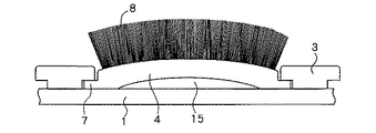
まず、軟質プラスチック材で作った植毛板4は回転方向及び逆回転方向を示す横手方向間において、中央部分を上方に少し反らせて成形している。実施する範囲は植毛板4の内端から外周端に至る間の部分で、リブ3とリブ3の間に取り付けて外周より見た場合、基台1と植毛板4の底面との間には僅かに山状の隙間15が生じている。その間隔は最大部分で5〜10mm程度とすることが望ましい。
ブラシ毛材8を植毛した植毛板4は基台1の外周端よりはめこんで取り付ける。
【0017】
他の方法としてリブ3とリブ3の間隔よりも横幅が僅かに広い平板状の植毛板4を用意し、横手方向に湾曲させながら、リブ3とリブ3の間に上部からはめ込み、終わった時点で手をはなすと、植毛板4は僅かに中央部分を上方に反らせた状態で取り付けられる。
【0018】
基台1と植毛板4との隙間15は通常山形となるが、植毛板4の厚みを内方より外周方向へと部分的に薄くしたり、切り込み線を入れたり、或いは植毛穴13の間隔を詰めて直線状に配置することにより、ミシン目を施したように折り曲げ易くなる。
また、植毛板4を一枚のものとしないで横方向に分割したり、或いは薄くしたものを上下に積層し、一部を固着したものとすれば湾曲が容易となる。これらは、隙間15の形状及び位置の設定の多少の変更を可能とするが、接床加圧により隙間15部分が消滅しないよう設定し、場合によっては可撓性の小突起やスポンジ材などの緩衝材を介在させることも考えられる。
【0019】
これら植毛板4の内端付近を基台1にねじ止めしたり、その他任意の方法で固着してもよい。
植毛板4をねじ止めする場合、内端付近のねじ止め個所を挟んで左右に切れ目を入れ、基台1に固定したとき、反り部分の波動に干渉されず、反りを伴わない個所とする。
反り部分の隙間15は接床時、電動床磨機の重圧によって僅かに変形し得るほどの柔軟性と弾性を植毛板4に付与しているので、ブラシ毛材8が短く摩耗しても、隙間15の僅少の変化が、クッションとなって床面の微凹凸に順応し、かつ、回転振動を吸収し、植毛角度の多様化と相まって研磨効果を向上させる。
接床圧力によって変化する個々の植毛板4に対する加圧状況は、常時波動的であり、僅少変形の反復であるため相当長期に亘って使用しても変形恒常化は促進されない。
【0020】
取り外すときは、隙間15にねじ廻しなどを差し込み、上方へ持ち上げれば容易にはずすことができる。
植毛板4は常に基台1側に押しつけた状態で使用するので作業中はずれることはない。
【0021】
何れの場合も、接床圧力は直接的に基台1にかからずリブ3の側面とに分散されるので、振動抑制効果を高める一因となっている。
植毛板4の反りの頂部より展開する植毛角度は45°以上下がると研磨効果が低下する場合もある。
反りの形状は、頂部を回転逆方向端に寄せて、回転方向に向けてゆるやかな下り傾斜を形成してもよいし、形状は任意である。
【0022】
振動発生の原因としては、床面の凹凸にブラシ台が反応するためで、その大半は回転時におけるブラシ台の外周部分に生じる。そこで、本発明者はブラシ毛材8を植毛した植毛板4の外方を基台1の外周端より突出させて振動を抑制することを考えた。
すなわち、植毛板4は隣の植毛板4と直接連続せず、しかも、植毛板4の突出した部分の上面には基台1が存在しないので、ブラシ台の外周部に発生した振動は、当初、当該植毛板4のみに限定され、次に水平波動となって内方へ伝達される。一方、その植毛板4の内方部分に生じた比較的小さな振動は垂直方向及び外方向へと水平伝達されるのであるが、このとき、外方より伝達された振動はほぼ同じ波長として互いに干渉し合い、振動を僅かに相殺する効果を奏する。
【0023】
リブ3の上部及び植毛板4に設けた突条7の一部を切欠いて洗剤滴下孔6としている。また、各植毛板4の突出部分は、ちょうどピアノの鍵盤が浮沈するように、逐次、僅少の浮沈を繰り返すことによって、振動を少なからず抑制する作用を発揮する。
この方法によるもう一つの利点としては、植毛板4のみを交換することで、ひとまわり大きめのブラシ台として活用することが可能となり、軽量化及び経費節減効果も極めて大きい。
本発明のリブ3の形状は連続形としても断続形としてもよく、形状は任意としてよい。植毛板4の形状及び洗剤滴下孔6の形状も任意としてよい。
【0024】
【実施例】
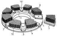
実施例1を図に基づいて説明する。図1は基台1部分の平面斜視図、図2はリブ3の中心を内端から外端方向に縦断した側面図である。図3は、正面から見て環状リブ9の直前部分の縦断面図、図4はブラシ毛材8を植毛した植毛板4を取り付けた底面斜視図である。1は円板状の基台を示していて、中央に円形の中央穴をあけている。基台1は下面から見た場合、幅広のリブ3を8条、内方から外周に向けて等間隔の放射状に設けている。
そして、リブ3の両外側の下端を各々切欠いて溝5を設けている。図1に示す基台1の上面は中央穴のまわりを円形の凸部2として一段高くし電動床磨機の下部に取り付け易くしている。下面のリブ3の反対位置に相当する基台1の上面には反対形状の凹部とした洗剤滴下孔6が形成されている。
洗剤滴下孔6は上面から見た場合、図1に示すように、一つになっている内端より3すじに分かれ、両側の凹部は溝5部分に連なっていて、後記する植毛板4の突条7部分との僅かなすきまからも、洗剤はブラシ毛材8を伝わって少しずつ床面へ滴下するようになっている。
【0025】
基台1の外周寄り付近には、洗剤の外側への流出を防ぐ環状リブ9が洗剤滴下孔6の上方を横断する形で設けられているので、環状リブ9の内側に滴下した洗剤流はすべて洗剤滴下孔6に入り、底面に設けられた円形の小穴10を通って床面へ流れる。洗剤滴下孔6の外周側は洗剤が飛散しないよう壁12でふさいでいる。
環状リブ9の外側にある上面の洗剤滴下孔6は、リブ3の溝5を設けるプラスチック成形上の技術的必要理由から設けたもので、図2に示すように内部では一つになっているが、環状リブ9の外側表面からは一滴の洗剤も流入することはない。
従って内部においても環状リブ9直下の外側はそこに壁を設け遮断してもよい。
【0026】
リブ3と、隣合うリブ3の間にちょうどはまる外周形状とした植毛板4を8個用意するが、植毛板4の両側下端には、リブ3に設けた溝5にはまる突条7をそれぞれ設けていて、植毛板の表面には多数のブラシ毛材8を直立させて植え込んでいる。
植毛板4を基台1の外周端からリブ3と隣合うリブ3の間に入れ、溝5にはまる突条7をそれぞれ合わせながら一杯に押し込み植毛板4と基台1の各外周部を一致させたのち、植毛板4の内端付近において、基台1と植毛板4とを木ねじ11を用い、ねじ止めして両者を固定している。以上のものは基台1に取り付けた植毛板4のブラシ毛材8を接床させ、ブラシ台を回転させながら磨いていく。
【0027】
実施例2を図5で示す。本発明のブラシ毛材8はナイロンなどブラシ用フィラメントに研磨粒子を含有させたものを主として使用している。そして長いブラシ毛材8の束を一定の長さに切断し、従来から広く利用されている植毛法によって植毛している。
そのほか、図5に示すものは前文で詳記したように、長いブラシ毛材8の一本乃至数本をジグザグに折り返してほぼ一定の長さにしたものを束ねて植毛したもので、先端には個々のループを形成している。たとえば、ブラシ毛材8の束の中央部分を2つに折り曲げU字型釘に挟んで植毛穴13に打ち込むなど任意の方法で植毛板4に植毛している。基台1及びリブ3部分は一体成形としないで、たとえば、上下2枚の同形とした円板状のものを用意し、上板に植毛板4のはまる切欠きを複数設け、その左右下端に突条7がはまる溝5を設けた後、下板を重ねてねじ止め固着、一体化としてもよい。この場合、切欠きとその隣りの切欠きの間部分がリブ3に相当するが、その個所に設ける洗剤滴下孔6の形状は任意としてもよい。
【0028】
実施例3を図に基づいて説明する。図6は植毛板4の要部を示す一部縦断面図で、植毛板4の表面に設けた多数の植毛穴13の上縁の一部を横手2方向に切欠いている。
すべてのブラシ毛材8はテンション加工が施されているので反発力が強く、束ねて植毛されたブラシ毛材8の植毛穴溝14に接する部分は、はじけたように扇状に展開し、植毛穴溝14内一杯にはまり込む。この部分の植毛密度は疎にして植毛角度は数本単位で変わっている。しかも、束ねたブラシ毛材8の中心部分は依然直立状態を保持しているので、いわゆる、毛腰は強く、電動床磨機の重量にも容易にヘタることはない。
ブラシ台は接床面積を拡げた状態で床面を効率よく磨いていく。
【0029】
実施例4を図に基づいて説明する。図7は植毛した植毛板4を平板状として、上方に反らしながら取り付けることを示す斜視図、図8はあらかじめ反りを設けた植毛板4の正面図。
図7に示す実施例は環状リブ9の反対面の同位置において、リブ3の両外側に角形に切欠いた爪受部16をそれぞれ設けている。両外側の下端はすでに溝5を設けているので、さらに、その上部を切欠くことになり、爪受部16から内部を見ると環状リブ9の底面が見えるが、爪受部16の設定位置及び形状は任意としてよい。
一方、軟質プラスチック材で作った平板状の植毛板4に設けた突条7には、リブ3に設けた爪受部16に対応させるものとして、角形の突起とした爪部17を設け、上方より、リブ3の溝5にはめたとき爪受部16の中に爪部17がぴったりはまる寸法としている。
【0030】
そのほか、爪受部16を角形の窓状とし、一方の爪部17の上部には小さな鉤状のフックを設けて、はめた後は外れないようにしていて、外すときは爪部17を押して窓の中に沈め、引き抜く方法を用いてよい。
取り付け後の爪部17はリブ3の表面に僅かに突出し、植毛板4の内外方向へのずれを防止している。この植毛板4の横手方向間の幅はリブ3とリブ3の間隔よりも少し広くしているが、単に横幅だけを広くした場合は取り付け後、内端方向が低くなる。外周方向への広がり傾斜角度を狭くなるよう調整することにより、内端と外周との間の高さを均一とすることが出来る。
取り付け方法は、まず、植毛板4を横手方向の上方に反らせながら湾曲させ、一側面の突条7部分を溝5に入れ、手で中央部分を押しながら他側の突条7をもう一方の溝5にはめる。外すときはその逆操作を行う。
平板状の植毛板4とする場合は、横手方向に数分割してもよく、また、表面に対し直立した植毛穴13を多数あけているので、反らしたとき、植毛しているブラシ毛材8も反りと同様な植毛角度を実現する。
【0031】
他に、植毛板4を平板状とせず、あらかじめ、横手方向の上方に反りを持たせて成形する方法がある。
図8で示しているが、基台1の外周端からリブ3とリブ3の間に挿し込んで取り付けるので爪受部16及び爪部17は設けない。反り面に対し、大体直立してあけた多数の植毛穴13を設けることで、ブラシ毛材8も大体反りなりの植毛角度を実現するのが好ましいが、必ずしも反りなりの植毛角度としなくてもよく、数段階の異なる植毛角度を実現してよい。
ブラシ毛材8の毛足は図8に示すように一定水準に揃えているが、多少の高低差は設けてもよい。
【0032】
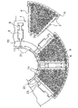
実施例5を図9、10に基づいて説明する。図9は要部を示す底面図、図10は同、植毛板4を拡大した図である。
基台1に等間隔で8条設けているリブ3は、前項と異なり中央の洗剤滴下孔6及び小穴10を廃し、残り2すじの洗剤滴下孔6は溝5との兼用として配置していて、拡大図10に示すようにリブ3の両外側の一部をそれぞれ大きく上面より切欠いてメインの洗剤滴下孔6を形成している。その位置は、上面に存在する環状リブ9の下面に一部かかっているが、植毛板4を取り付けたとき、その部分は植毛板4の突条7に覆われるので、洗剤が、環状リブ9の外側に流出することはない。リブ3は内端から外端までの幅を均一としている。一方、取り付ける植毛板4の突条7の同位置も切欠いて洗剤滴下孔6を設けている。リブ3に植毛板4を取り付けたとき、両者は部分的に大きく重なって上下面を貫通する洗剤滴下孔6を形成する。
また、植毛板4の内端には、中央穴に向けて併列する2本の脚を設け、その先端には各々外向きのフック19を形成している。中央穴の縁にはフック19が、ちょうどはまるフック受け21を間隔をあけてフック19と同数設け、フック19をそれぞれはめている。フック19を外すときは指先で併列するフック19を寄せて外方へ引き抜くと容易に外すことができる。
【0033】
基台1は軽量化を図るため、上面の凸部2の下面の相当する部分に深めのくぼみ20を設け、くぼみ20が変形しないよう等間隔で8条の補強リブ22を設けている。リブ3の内端にも補強部材23を設けている。
【0034】
その他、本発明の各実施例において、基台1と植毛板4との間に、平均的な隙間を設け、その中に緩衝材としてスポンジ板などを介在させてもよい。
また、洗剤液の飛沫を通さない程度の網目を有する布状のネットを用意し、長手方向の一端を上記の隙間に挿入して取り付けたのち、ネットの中間を基台1の外周端において直角に折り曲げ、もう一方の端部を垂らして床面に接触させ、ときに、床面に滞留する洗剤液の飛沫防止材として用いることも考えられる。
【0035】
【発明の効果】
本発明に係るタンク付電動床磨機用ブラシ台においては、基台1の上面にリブを設けていないが下面にリブ3を設けている。このため、強度的には問題がない。また、上面にリブを設けていないため、洗浄液がリブに強く当たって望まない方向へ飛散するということもない。そして、このものにおいては基台1の上面外周寄りに環状リブ9を設け基台1に洗剤滴下孔6を設けている。このため、基台1上に流下する洗剤は環状リブ9に遮られて外方へ飛び散ることなく的確に洗剤滴下孔6から流下していく。基台1に設けた環状リブ9は基台1のゆがみ防止及び補強の作用もする。
従来は複数の洗剤滴下孔を複数のリブと別別の位置に設けていたため、場所を取られて基台の耐力にも影響が出ていた。しかし、請求項1に係るタンク付電動床磨機用ブラシ台においては、リブ3の位置に洗剤滴下孔6を設けているため、場所も取られず基台1の耐力が落ちることもない。さらに、リブ3を利用して洗剤滴下孔6を設けるため、洗剤滴下孔6を大きくすることができる。したがって、洗剤をスムースに流下させるようにすることができる。
【図面の簡単な説明】
【図1】実施例の基台の平面斜視図
【図2】実施例のリブ側面縦断面図
【図3】実施例のリブ正面縦断面図
【図4】実施例1の底面斜視図
【図5】実施例2を示すブラシ毛材の要部正面図
【図6】実施例3の要部を示す一部縦断面図
【図7】実施例4の要部を示す斜視図
【図8】実施例4の正面図
【図9】実施例5の要部を示す底面図
【図10】実施例5の要部拡大図
【符号の説明】
1 基台
3 リブ
4 植毛板
5 溝
6 洗剤滴下孔
7 突条
8 ブラシ毛材
9 環状リブ
10 小穴
13 植毛穴
14 植毛穴溝
15 隙間
16 爪受部
17 爪部
18 張り出し部
19 フック
20 くぼみ
21 フック受け
22 補強リブ
23 補強部材
[0001]
BACKGROUND OF THE INVENTION
The present invention relates to a brush base used by being attached to an electric floor polisher with a tank used for floor cleaning of a building or the like.
[0002]
[Prior art]
Although there has been a conventional method of cleaning the floor surface by attaching a detergent solution tank to the top of the electric floor polisher and dropping the detergent solution, the center of gravity is high because the tank is installed at a high position and the tank is heavy. Because it became expensive and difficult to use, it was not so popular.
Later, with the advent of improved models, it gradually began to spread, but the accompanying brush stand plays a role in preventing twisting of the base by providing a plurality of ribs between the inside and outside of the upper surface of the resin or aluminum base , Using a small detergent drip hole in the vicinity of the rib, no progress has been seen for decades.
[0003]
[Problems to be solved by the invention]
When a conventional brush base is used in a high-speed electric floor polisher with a tank that has been developed in recent years, the detergent solution is strongly applied to a plurality of ribs provided between the inside and outside of the upper surface, and the detergent solution scatters in an undesired direction. Although there was a drawback that it did not flow sufficiently in the detergent dripping hole, it was not possible to provide a long and slender large detergent dripping hole due to strength.
[0004]
The ribs are necessary as reinforcements for reinforcing the base, but if the position is simply moved from the upper surface to the lower surface, the ribs will interfere with the installation of the brush bristle material, and the setting position of the detergent dripping hole It was difficult.
[0005]
The present invention has a high polishing effect and a brush stand that can surely flow into the detergent dropping holes without splashing the detergent liquid at all, regardless of the amount of the detergent liquid dripping onto the upper surface of the base of the brush base that rotates at high speed. The purpose is to provide an efficient brush stand with little vibration.
[0006]
[Means for Solving the Problems]
In order to achieve the above object, the brush stand for an electric floor polisher with a tank according to the present invention is as follows. That is, the brush stand for the electric floor polisher with a tank according to claim 1 is provided with the annular rib 9 near the outer periphery of the upper surface of the disk-shaped base 1, and the lower surface is spaced from the inner side toward the outer periphery. A plurality of ribs 3 are provided, and a flocking plate 4 in which a large number of bristle bristle materials 8 are implanted on the lower surface so as to fit between the ribs 3 is attached between the ribs 3. A plurality of shapes are provided on the base 1 from the inner side to the outer periphery at the positions where the ribs 3 are provided.
The brush stand for the electric floor polisher with a tank according to claim 2 is provided with an annular rib 9 near the outer periphery of the upper surface of the disk-shaped base 1, and a plurality of lower surfaces are spaced from the inside toward the outer periphery. The ribs 3 are provided, and a flocking plate 4 in which a large number of bristle bristle materials 8 are planted on the lower surface so as to fit between the ribs 3 is attached between the ribs 3, and a plurality of elongated slit-like detergent dropping holes 6 are formed. Is provided inside the annular rib 9 from the inner side toward the outer periphery.
When the brush stand according to claim 1 or 2 is attached under an electric floor polisher with a tank and the brush stand is rotated while the detergent is flowing down from the tank, the detergent flowing down on the base 1 is the base. 1 is prevented from being scattered to the outer periphery by the annular rib 9 provided near the outer periphery of the upper surface, and flows down from the detergent dropping hole 6 provided in the base 1.
[0007]
DETAILED DESCRIPTION OF THE INVENTION
The brush stand for the electric floor polisher with a tank according to the claims is formed in the center of the disk-shaped base 1 in order to attach it to the rotating body at the lower part of the electric floor polisher. Is provided with a circular convex portion 2, and in parallel with the outer periphery closer to the outer periphery, around the convex strip for preventing the detergent liquid from splashing and for preventing distortion and reinforcement of the base 1.
Hereinafter, the detergent liquid is described as a detergent. About the upper surface and lower surface of the base 1, it demonstrates as the case where the surface is seen from the top, respectively. On the lower surface of the base 1, a plurality of wide ribs 3 are provided radially from the inside toward the outer periphery at equal intervals so as to prevent distortion and reinforce the base 1. The lower ends on both outer sides of each rib 3 are cut out to provide grooves 5 for holding the flocking plate 4 to be described later, and a detergent dripping hole 6 is formed on the upper surface of the base 1 opposite to the rib 3.
[0008]
A plurality of fan-like flocking plates 4 having an outer peripheral shape that fits between the ribs 3 and 3 are prepared. At the lower ends of both sides of the flocking plate 4, protrusions 7 that fit into the grooves 5 provided in the ribs 3 are provided. In addition, a large number of brush bristle materials 8 containing abrasive particles are vertically planted on the surface of the flocking plate 4.
After the flocking plate 4 is fitted from the outer peripheral end between the rib 3 and the adjacent rib 3, a wood screw 11 is screwed between the base 1 and the inner end of the flocking plate 4 to fix them. As a fixing method, the base 1 part in contact with the vicinity of the inner end of the flocking plate 4 is raised, and an unevenness is provided between the two, and a combination of unevenness parts and a male and female cloth fasteners are connected like a train coupler. It may be fixed by any method such as using and fixing.
[0009]
The brush bristle material 8 is obtained by cutting a bundle of long bristle materials to a certain length using a cutting machine, and folding one or several long brush bristle materials 8 into a zigzag shape so as to have a substantially constant length. A bundle may be used. Folding the center part of the bunch of brush bristle material 8 in a circular flock hole 13 that has been widely used in the past, and then attaching it with a U-shaped nail or fine wire sandwiched, Can also be used.
The brush bristle material 8 formed in a zigzag form and flocked forms a loop on each of the hair tips, and when used, the loop portion is crushed and contacts the floor surface on average. And the polishing effect is greatly improved by expanding the floor contact area. At the same time, by repeating the pressure deformation of the loop portion, it plays the role of a cushion, so that the rotational vibration is reduced, which is effective in reducing the worker's fatigue.
[0010]
Further, for example, if each of the different types of brush hair materials 8 of A and B are combined and folded back in a zigzag, complete blending of the different types of brush hair materials 8 which was impossible in the past is realized, and the mixed planting ratio As a matter of course, there is an advantage that two operations of removing the streaks on the floor left by the loose brush bristle material 8 with coarse meshes with the fine brush bristle material 8 can be done once.
The inventor of the present invention invented crushing and using the brush bristle material 8 in a ring shape, but in this case, the formed loop portion does not uniformly touch the floor, and initially the ring-shaped surface layer Although there was a defect that only the part touches the floor and the inner layer does not touch the floor, the problem was solved by zigzag folding. The brush bristle material 8 does not overlap with the guruguru, is wound up in a spiral shape, and then brought to one place and bundled to produce the same effect as zigzag folding.
In addition, the loop part disappears with use, but the brush bristle material 8 is planted and, as a result of applying a working pressure for a long time, hair fuzz is generated, and the hair ends after the loop part breakage are varied over a long period thereafter. Maintains a proper angle and maintains the polishing effect.
[0011]
The brush bristle material 8 containing the abrasive particles does not increase the polishing effect because the floor contact area is small when the brush base is manufactured with a small amount of use. On the other hand, if the brush bristle material 8 is densely planted so that there is no room for standing cones, the effect becomes low when the brush bristle material 8 to be used is thick.
For example, the same amount of brush bristle material 8 having a thickness of 1 mm was used to produce a scrubbing brush and a brush stand, respectively. As a result of the use experiment, scrubbing was much more effective than the brush stand.
That is, the brush base requires a certain implantation density and is configured with a limited flocking angle, whereas the scrubbing brush is sparse enough to clearly recognize each brush bristle material 8 used. In addition, the configuration angle of the brush bristle material 8 changes one by one, and it touches the floor other than the tip portion.
[0012]
A number of circular flocking holes 13 are provided on the surface of the flocking plate 4 for flocking the brush bristle material 8.
The present inventor has considered to leave an upright flocked portion in the floor contact portion of the brush bristle material 8 so as not to get loose due to development and load of various flocking angles so that the brush bristle material 8 is as small as possible. .
For example, when the diameter of the circular flock hole 13 is 8 mm and the depth is 15 mm, the flock hole groove 14 is provided with a depth of 10 mm from the upper edge, a width of about 3 mm, and a length dimension of 3 mm or more. . The planted bristle material 8 partially enters the planted hole groove 14 due to an elastic repulsive force or a load pressure, and the portion develops an angle in a fan shape, resulting in a height difference. Moreover, the brush bristle material 8 leaves an upright flocked portion that becomes a core effective for load bearing. When various flocking angles are added to the brush bristle material 8, it expands and the floor contact area is expanded. After flocking, the hair tips are trimmed and aligned horizontally.
[0013]
Since the depth and width of the flock hole 14 vary depending on the hardness, amount and thickness of the brush bristle material 8 used, it cannot be standardized uniformly, but the tip of the brush bristle material 8 is scattered. The effect is applicable not only to the present invention but also to all brush stands for electric floor polishers.
The shape of the flock hole 14 may be a rectangle or a triangle, or may be one direction or two directions as shown in FIG.
[0014]
The direction of the flock hole 14 is preferably between the inner and outer directions of the flock plate 4, but may be provided between the lateral directions according to the rotation, and does not necessarily point to the center line of the flock hole 13. Also good.
The flocking hole groove 14 may be provided in advance in the plastic flocking plate 4 together with the individual flocking holes 13 by molding, but from the beginning, a flotation line continuous in the vertical direction or the horizontal direction of the flocking plate 4 is provided to provide the flocking hole groove 14. Even if the flock hole 13 is formed on the flock hole groove 14, the desired effect is obtained.
The degree of development of the flocking angle of the brush bristle material 8 is mainly adjusted by the set depth of the flocking hole groove 14.
[0015]
In addition, the flocking plate 4 itself is cushioned to absorb rotational vibrations, greatly reducing the vibration transmitted to the operator even if the bristle of the brush bristle material 8 is shortened, and further changing the flocking angle. By doing so, the polishing effect was enhanced.
[0016]
First, the flocking plate 4 made of a soft plastic material is formed by slightly bending the center portion upward between the transverse directions indicating the rotation direction and the reverse rotation direction. The range to be implemented is the part from the inner end to the outer peripheral end of the flocking plate 4, and when it is attached between the ribs 3 and 3 and viewed from the outer periphery, it is between the base 1 and the bottom surface of the flocking plate 4. A slightly mountain-shaped gap 15 is generated. The distance is desirably about 5 to 10 mm at the maximum portion.
The flocking plate 4 on which the brush bristle material 8 has been flocked is attached by fitting from the outer peripheral end of the base 1.
[0017]
As another method, a flat flocking plate 4 having a width slightly wider than the interval between the ribs 3 and 3 is prepared, and is fitted from the upper part between the ribs 3 and 3 while being curved in the transverse direction. When the hand is released, the flocking plate 4 is attached with the center portion slightly bent upward.
[0018]
The gap 15 between the base 1 and the flocking plate 4 is usually mountain-shaped, but the thickness of the flocking plate 4 is partially reduced from the inside toward the outer periphery, a cut line is inserted, or the spacing between the flocking holes 13 By arranging and arranging in a straight line, it becomes easy to bend as perforated.
In addition, if the flock plate 4 is not divided into one piece, it is divided in the lateral direction, or thin pieces are stacked one above the other and a part thereof is fixed, so that the bending becomes easy. These allow for a slight change in the setting of the shape and position of the gap 15 but are set so that the gap 15 portion does not disappear due to floor contact pressure, and in some cases, such as flexible small protrusions and sponge materials It is also possible to interpose a buffer material.
[0019]
The vicinity of the inner end of these flocking plates 4 may be screwed to the base 1 or may be fixed by any other method.
When the flocking plate 4 is screwed, a notch is made on the left and right sides of the screwing portion near the inner end, and when it is fixed to the base 1, the portion is not interfered with the wave of the warped portion and is not warped.
Since the gap 15 in the warped portion gives the flocking plate 4 flexibility and elasticity that can be slightly deformed by the heavy pressure of the electric floor polisher when contacting the floor, even if the brush bristle material 8 is worn shortly, A slight change in the gap 15 becomes a cushion, adapts to fine irregularities on the floor surface, absorbs rotational vibration, and improves the polishing effect in combination with diversification of the flocking angle.
The pressurization state of each flocking plate 4 that changes depending on the floor contact pressure is always wave-like, and since it is a slight deformation repetition, the deformation constantization is not promoted even if used for a considerable period of time.
[0020]
When removing, it can be easily removed by inserting a screwdriver or the like into the gap 15 and lifting it upward.
Since the flocking plate 4 is always used while pressed against the base 1 side, it does not slip during operation.
[0021]
In either case, the floor contact pressure is not directly applied to the base 1 but is distributed to the side surfaces of the ribs 3, which contributes to an increase in the vibration suppressing effect.
When the flocking angle developed from the warp top of the flocking plate 4 is lowered by 45 ° or more, the polishing effect may be lowered.
The shape of the warp may be a gentle downward slope toward the rotational direction by bringing the top portion toward the rotation reverse direction end, and the shape is arbitrary.
[0022]
The cause of the vibration is that the brush base reacts to the unevenness of the floor surface, and most of it occurs in the outer peripheral portion of the brush base during rotation. Then, this inventor considered suppressing the vibration by making the outer side of the flocking board 4 which planted the brush bristle material 8 protrude from the outer peripheral end of the base 1. FIG.
That is, the flocking plate 4 is not directly continuous with the adjacent flocking plate 4, and the base 1 does not exist on the upper surface of the protruding portion of the flocking plate 4, so that the vibration generated on the outer peripheral portion of the brush base is initially This is limited to the flock plate 4 and is then transmitted inward as a horizontal wave. On the other hand, relatively small vibrations generated in the inner portion of the flocking plate 4 are transmitted horizontally in the vertical direction and the outer direction. At this time, the vibrations transmitted from the outside interfere with each other with substantially the same wavelength. And has the effect of slightly canceling out vibrations.
[0023]
The upper part of the rib 3 and a part of the protrusion 7 provided on the flocking plate 4 are notched to form the detergent dropping hole 6. Further, the protruding portion of each flocking plate 4 exerts an effect of suppressing vibrations by repeating slight ups and downs in succession so that the piano keyboard just rises and falls.
Another advantage of this method is that by replacing only the flocking plate 4, it can be used as a brush table that is slightly larger in size, and the effects of weight reduction and cost saving are extremely great.
The shape of the rib 3 of the present invention may be continuous or intermittent, and the shape may be arbitrary. The shape of the flocking plate 4 and the shape of the detergent dropping hole 6 may be arbitrary.
[0024]
【Example】
Example 1 will be described with reference to the drawings. FIG. 1 is a plan perspective view of the base 1 portion, and FIG. 2 is a side view in which the center of the rib 3 is vertically cut from the inner end toward the outer end. FIG. 3 is a longitudinal sectional view of a portion immediately before the annular rib 9 as viewed from the front, and FIG. 4 is a bottom perspective view to which a flocking plate 4 having a brush bristle material 8 planted is attached. Reference numeral 1 denotes a disk-shaped base, which has a circular central hole in the center. When viewed from the bottom surface, the base 1 is provided with eight wide ribs 3 radially from the inside toward the outer periphery.
And the groove | channel 5 is provided by notching the both lower ends of the rib 3 each. The upper surface of the base 1 shown in FIG. 1 is raised one step around the central hole as a circular convex portion 2 so that it can be easily attached to the lower portion of the electric floor polisher. On the upper surface of the base 1 corresponding to the position opposite to the rib 3 on the lower surface, a detergent dropping hole 6 is formed as a recess having an opposite shape.
When viewed from the top, the detergent dripping hole 6 is divided into three streaks from one inner end as shown in FIG. 1, and the concave portions on both sides are continuous with the groove 5 portion. Even from a slight gap with the ridge 7, the detergent is gradually dropped onto the floor surface along the brush bristle material 8.
[0025]
In the vicinity of the outer periphery of the base 1, an annular rib 9 that prevents the detergent from flowing out is provided so as to cross over the detergent dripping hole 6. All enter the detergent dropping hole 6 and flow to the floor through the circular small hole 10 provided on the bottom surface. The outer peripheral side of the detergent dropping hole 6 is blocked by a wall 12 so that the detergent does not scatter.
The detergent dropping hole 6 on the upper surface outside the annular rib 9 is provided for reasons of technical necessity in plastic molding in which the groove 5 of the rib 3 is provided, and is one inside as shown in FIG. However, a drop of detergent does not flow from the outer surface of the annular rib 9.
Therefore, inside the inside, the outside just below the annular rib 9 may be blocked by providing a wall there.
[0026]
Eight flocked plates 4 having an outer peripheral shape that fits between the ribs 3 and the adjacent ribs 3 are prepared. At the lower ends of both sides of the flocked plate 4, protrusions 7 that fit into the grooves 5 provided on the ribs 3 are respectively provided. It is provided, and many brush bristle materials 8 are planted upright on the surface of the flocking plate.
The flocking plate 4 is inserted between the rib 3 adjacent to the rib 3 from the outer peripheral end of the base 1 and pushed into the groove 5 while fitting the protrusions 7 that fit into the grooves 5, and the outer peripheral portions of the flocking plate 4 and the base 1 are matched. Then, in the vicinity of the inner end of the flocking plate 4, the base 1 and the flocking plate 4 are screwed together using wood screws 11 to fix them together. In the above, the brush bristle material 8 of the flocking plate 4 attached to the base 1 is brought into contact with the floor and polished while rotating the brush base.
[0027]
Example 2 is shown in FIG. The brush bristle material 8 of the present invention mainly uses a brush filament such as nylon containing abrasive particles. A bundle of long brush bristle materials 8 is cut into a certain length, and is planted by a flocking method that has been widely used.
In addition, as shown in detail in the previous sentence, what is shown in FIG. 5 is one in which one or several long bristle bristle materials 8 are folded back in a zigzag manner and bundled to obtain a substantially constant length. Form individual loops. For example, the central portion of the bundle of the brush bristle material 8 is folded in two and sandwiched between U-shaped nails and driven into the flock hole 13 so that the flocking plate 4 is flocked. The base 1 and the rib 3 portion are not integrally molded. For example, two upper and lower identical disk-shaped ones are prepared, and a plurality of notches into which the flocking plate 4 is fitted are provided on the upper plate, and left and right lower ends thereof are provided. After providing the groove 5 into which the ridge 7 is fitted, the lower plate may be stacked and fixed with screws and integrated. In this case, the portion between the notch and the adjacent notch corresponds to the rib 3, but the shape of the detergent dropping hole 6 provided at that portion may be arbitrary.
[0028]
A third embodiment will be described with reference to the drawings. FIG. 6 is a partial longitudinal sectional view showing a main part of the flocking plate 4, and a part of the upper edge of a number of flocking holes 13 provided on the surface of the flocking plate 4 is cut away in the transverse direction 2.
Since all the brush bristle materials 8 are tensioned, the repulsive force is strong, and the portion of the brush bristle material 8 that is bundled and planted in contact with the flocking hole groove 14 expands in a fan-like shape so that it flies. Fits into the groove 14. The flocking density in this part is sparse, and the flocking angle changes in units of several. In addition, since the central portion of the bundled brush bristle material 8 is still in an upright state, the so-called bristle is strong and does not easily stick to the weight of the electric floor polisher.
The brush stand efficiently polishes the floor with the floor contact area expanded.
[0029]
Example 4 will be described with reference to the drawings. FIG. 7 is a perspective view showing that the flocked plate 4 that has been flocked is flat and attached while warping upward, and FIG. 8 is a front view of the flocked plate 4 that has been warped in advance.
In the embodiment shown in FIG. 7, at the same position on the opposite surface of the annular rib 9, claw receiving portions 16 that are notched in a square shape are provided on both outer sides of the rib 3. Since the grooves 5 are already provided at the lower ends of both outer sides, the upper part thereof is further cut out, and the bottom surface of the annular rib 9 can be seen from the inside of the claw receiving part 16, but the setting position of the claw receiving part 16 The shape may be arbitrary.
On the other hand, the protrusion 7 provided on the flat flocking plate 4 made of a soft plastic material is provided with a claw portion 17 which is a square protrusion, corresponding to the claw receiving portion 16 provided on the rib 3, Thus, the size of the claw portion 17 fits into the claw receiving portion 16 when fitted into the groove 5 of the rib 3.
[0030]
In addition, the claw receiving portion 16 has a rectangular window shape, and a small hook-like hook is provided on the upper portion of one claw portion 17 so that it does not come off after being fitted. A method of sinking into a window and pulling it out may be used.
The nail | claw part 17 after attachment protrudes slightly on the surface of the rib 3, and the shift | offset | difference to the inner / outer direction of the flocking board 4 is prevented. The width between the lateral directions of the flocking plate 4 is slightly wider than the interval between the ribs 3 and 3. However, when only the lateral width is increased, the inner end direction becomes lower after attachment. The height between the inner end and the outer circumference can be made uniform by adjusting the spread inclination angle in the outer circumference direction to be narrow.
The attachment method is as follows. First, the flock plate 4 is bent while curving upward in the lateral direction, the protruding portion 7 on one side is put into the groove 5, and the protruding portion 7 on the other side is pushed to the other side while pushing the center portion by hand. Fit into groove 5. When removing, reverse the operation.
When the flat flocking plate 4 is used, it may be divided into several in the transverse direction, and since many flocking holes 13 that are upright with respect to the surface are formed, the brush bristle material 8 that has been flocked when warped. Achieves the same flocking angle as warpage.
[0031]
In addition, there is a method in which the flocked plate 4 is not formed into a flat plate shape, and is previously formed with a warp upward in the lateral direction.
Although shown in FIG. 8, since it inserts and attaches between the rib 3 and the rib 3 from the outer peripheral end of the base 1, the nail | claw receiving part 16 and the nail | claw part 17 are not provided. It is preferable that the brush bristle material 8 also achieves a substantially flocked flocking angle by providing a large number of flocked holes 13 that are roughly upright with respect to the warped surface. Well, several different flocking angles may be realized.
The bristle feet of the brush bristle material 8 are aligned at a certain level as shown in FIG. 8, but a slight difference in height may be provided.
[0032]
A fifth embodiment will be described with reference to FIGS. FIG. 9 is a bottom view showing the main part, and FIG. 10 is an enlarged view of the flocking plate 4.
Unlike the previous item, the ribs 3 provided on the base 1 at eight equal intervals eliminate the central detergent dropping hole 6 and the small hole 10, and the remaining two streak detergent dropping holes 6 are also used as grooves 5. As shown in the enlarged view 10, the main detergent dropping hole 6 is formed by partially cutting off both the outer sides of the rib 3 from the upper surface. The position is partly on the lower surface of the annular rib 9 existing on the upper surface. However, when the flocking plate 4 is attached, the portion is covered with the protrusions 7 of the flocking plate 4, so that the detergent is removed from the annular rib 9. Will not flow outside. The rib 3 has a uniform width from the inner end to the outer end. On the other hand, the same position of the protrusion 7 of the flocking plate 4 to be attached is also cut out to provide a detergent dropping hole 6. When the flocking plate 4 is attached to the rib 3, they both partially overlap and form the detergent dropping hole 6 penetrating the upper and lower surfaces.
Moreover, two legs juxtaposed toward the center hole are provided at the inner end of the flocking plate 4, and outward hooks 19 are formed at the ends of the legs. At the edge of the central hole, the hook 19 is provided with the same number of hook receivers 21 as the hooks 19 at intervals, and the hooks 19 are respectively fitted. When the hook 19 is removed, it can be easily removed by bringing the hooks 19 aligned with the fingertips and pulling them outward.
[0033]
In order to reduce the weight of the base 1, a deep recess 20 is provided in a corresponding portion of the lower surface of the convex portion 2 on the upper surface, and eight reinforcing ribs 22 are provided at equal intervals so that the recess 20 does not deform. A reinforcing member 23 is also provided at the inner end of the rib 3.
[0034]
In addition, in each Example of this invention, you may provide an average clearance gap between the base 1 and the flocking board 4, and may interpose a sponge board etc. as a buffering material in it.
In addition, after preparing a cloth-like net having a mesh that does not allow the detergent liquid to pass through and inserting one end in the longitudinal direction into the gap, the middle of the net is perpendicular to the outer peripheral end of the base 1. It is also conceivable to use it as a splash preventing material for the detergent liquid that stays on the floor surface.
[0035]
【The invention's effect】
In the brush stand for an electric floor polisher with a tank according to the present invention, no rib is provided on the upper surface of the base 1, but the rib 3 is provided on the lower surface. For this reason, there is no problem in strength. Further, since no rib is provided on the upper surface, the cleaning liquid does not hit the rib strongly and scatters in an undesired direction. And in this thing, the annular rib 9 is provided near the upper surface outer periphery of the base 1, and the detergent dripping hole 6 is provided in the base 1. FIG. For this reason, the detergent flowing down on the base 1 is blocked by the annular rib 9 and accurately flows down from the detergent dropping hole 6 without splashing outward. The annular rib 9 provided on the base 1 also serves to prevent distortion and reinforce the base 1.
Conventionally, since a plurality of detergent dropping holes are provided at positions different from the plurality of ribs, the space is taken and the yield strength of the base is affected. However, in the brush base for an electric floor polisher with a tank according to claim 1, since the detergent dropping hole 6 is provided at the position of the rib 3, the space is not taken and the proof strength of the base 1 is not lowered. Furthermore, since the detergent dripping hole 6 is provided using the rib 3, the detergent dripping hole 6 can be enlarged. Therefore, the detergent can be made to flow smoothly.
[Brief description of the drawings]
FIG. 1 is a plan perspective view of a base of an embodiment. FIG. 2 is a longitudinal sectional view of a rib side of the embodiment. FIG. 3 is a longitudinal sectional view of a rib front of the embodiment. 5] Front view of main part of brush bristle material showing Example 2. [FIG. 6] Partial longitudinal sectional view showing the main part of Example 3. [FIG. 7] Perspective view showing the main part of Example 4. [FIG. Front view of Example 4 [FIG. 9] Bottom view showing essential parts of Example 5. [FIG. 10] Enlarged view of essential parts of Example 5. [Explanation of symbols]
DESCRIPTION OF SYMBOLS 1 Base 3 Rib 4 Flocking board 5 Groove 6 Detergent dripping hole 7 Rib 8 Brush bristle material 9 Annular rib 10 Small hole 13 Flocking hole 14 Flocking hole groove 15 Claw 16 Claw receiving part 17 Claw part 18 Overhang part 19 Hook 20 Indentation 21 Hook receiver 22 Reinforcing rib 23 Reinforcing member

Claims (2)

円板状の基台(1)の上面の外周寄りに環状リブ(9)を設けて下面には内方から外周へ向け間隔をあけて複数のリブ(3)を設け、各リブ(3)の間にちょうどはまる形状として下面に多数のブラシ毛材(8)を植毛した植毛板(4)を各リブ(3)の間にそれぞれ取り付け、細長いスリット状の洗剤滴下孔(6)の複数状をリブ(3)を設けた位置において内方から外周へ向け基台(1)に設けたタンク付電動床磨機用ブラシ台。An annular rib (9) is provided near the outer periphery of the upper surface of the disk-shaped base (1), and a plurality of ribs (3) are provided on the lower surface at intervals from the inside to the outer periphery, and each rib (3) A flocking plate (4) in which a large number of brush bristle materials (8) are planted on the lower surface is attached between the ribs (3) as a shape that fits in between, and a plurality of elongated slit-shaped detergent dropping holes (6) are formed. A brush base for an electric floor polisher with a tank provided on the base (1) from the inside toward the outer periphery at the position where the rib (3) is provided . 円板状の基台(1)の上面の外周寄りに環状リブ(9)を設けて下面には内方から外周へ向け間隔をあけて複数のリブ(3)を設け、各リブ(3)の間にちょうどはまる形状として下面に多数のブラシ毛材(8)を植毛した植毛板(4)を各リブ(3)の間にそれぞれ取り付け、細長いスリット状の洗剤滴下孔(6)の複数状を内方から外周へ向け環状リブ(9)の内側に設けたタンク付電動床磨機用ブラシ台。An annular rib (9) is provided near the outer periphery of the upper surface of the disk-shaped base (1), and a plurality of ribs (3) are provided on the lower surface at intervals from the inside to the outer periphery, and each rib (3) A flocking plate (4) in which a large number of brush bristle materials (8) are planted on the lower surface is attached between the ribs (3) as a shape that fits in between, and a plurality of elongated slit-shaped detergent dropping holes (6) are formed. A brush stand for an electric floor polisher with a tank provided on the inside of the annular rib (9) from the inside toward the outside .
JP2000314464A 1999-11-10 2000-09-08 Brush stand for electric floor polisher with tank Expired - Fee Related JP4232332B2 (en)

Priority Applications (1)

Application Number Priority Date Filing Date Title
JP2000314464A JP4232332B2 (en) 1999-11-10 2000-09-08 Brush stand for electric floor polisher with tank

Applications Claiming Priority (7)

Application Number Priority Date Filing Date Title
JP35490399 1999-11-10
JP2000040281 2000-01-14
JP2000-202918 2000-06-01
JP2000202918 2000-06-01
JP2000-40281 2000-06-01
JP11-354903 2000-06-01
JP2000314464A JP4232332B2 (en) 1999-11-10 2000-09-08 Brush stand for electric floor polisher with tank

Publications (3)

Publication Number Publication Date
JP2002051836A JP2002051836A (en) 2002-02-19
JP2002051836A5 JP2002051836A5 (en) 2006-06-08
JP4232332B2 true JP4232332B2 (en) 2009-03-04

Family

ID=27480743

Family Applications (1)

Application Number Title Priority Date Filing Date
JP2000314464A Expired - Fee Related JP4232332B2 (en) 1999-11-10 2000-09-08 Brush stand for electric floor polisher with tank

Country Status (1)

Country Link
JP (1) JP4232332B2 (en)

Cited By (1)

* Cited by examiner, † Cited by third party
Publication number Priority date Publication date Assignee Title
WO2019175730A1 (en) * 2018-03-13 2019-09-19 3M Innovative Properties Company Floor bristle brush assembly

Families Citing this family (3)

* Cited by examiner, † Cited by third party
Publication number Priority date Publication date Assignee Title
CN101273987A (en) * 2002-06-03 2008-10-01 诺瓦提斯公司 Use of substituted cyanopyrrolidines and combination preparations containing them for treating hyperlipidemia and associated diseases
JP2009045215A (en) * 2007-08-20 2009-03-05 Rinrei:Kk Rotating cleaning implement
KR101925965B1 (en) 2016-07-14 2019-02-26 엘지전자 주식회사 a Robot cleaner and a maintenance device for the same

Cited By (1)

* Cited by examiner, † Cited by third party
Publication number Priority date Publication date Assignee Title
WO2019175730A1 (en) * 2018-03-13 2019-09-19 3M Innovative Properties Company Floor bristle brush assembly

Also Published As

Publication number Publication date
JP2002051836A (en) 2002-02-19

Similar Documents

Publication Publication Date Title
CA2575767C (en) Toothbrush having cleaning elements forming a contoured cleaning profile
US8418306B2 (en) Toothbrush and process for producing the same
JP4232332B2 (en) Brush stand for electric floor polisher with tank
US5979024A (en) Holder for fibrous product
JP2003053665A (en) Dresser
US2734212A (en) Brush structure
US3327338A (en) Floor and baseboard cleaning attachment
JP2006271644A (en) Washing tool
JP2001186929A (en) Brush cleaning tool
JPH09238876A (en) Cleaning utensil
KR101461443B1 (en) Door mat
JP2000152822A (en) Rotary floor surface washing brush
JPH08131385A (en) Brush base for electric floor polisher
JP2018201712A (en) Cleaning tool
WO1996028066A1 (en) Cleaning equipment
JP2001037694A (en) Motor-driven brush base for polishing floor and water splash preventive tool
JP2000093371A (en) Pad holder for electric floor polisher
JP3564667B1 (en) Substrate for water absorption mat and water absorption mat
JPH08196498A (en) Cleaning tool
CN210247877U (en) Detachable pet cushion
JP3085753U (en) Rotary floor cleaning brush
JP4329924B2 (en) Polishing machine
JP2005287531A (en) Sponge cleaner
JP4352534B2 (en) Wiping type eraser for writing board
CA2922935A1 (en) Cleaning implement with resilient projections

Legal Events

Date Code Title Description
A521 Written amendment

Free format text: JAPANESE INTERMEDIATE CODE: A523

Effective date: 20060317

A621 Written request for application examination

Free format text: JAPANESE INTERMEDIATE CODE: A621

Effective date: 20060317

RD03 Notification of appointment of power of attorney

Free format text: JAPANESE INTERMEDIATE CODE: A7423

Effective date: 20060317

A131 Notification of reasons for refusal

Free format text: JAPANESE INTERMEDIATE CODE: A131

Effective date: 20080812

A521 Written amendment

Free format text: JAPANESE INTERMEDIATE CODE: A523

Effective date: 20080911

A521 Written amendment

Free format text: JAPANESE INTERMEDIATE CODE: A523

Effective date: 20080911

TRDD Decision of grant or rejection written
A01 Written decision to grant a patent or to grant a registration (utility model)

Free format text: JAPANESE INTERMEDIATE CODE: A01

Effective date: 20081125

A01 Written decision to grant a patent or to grant a registration (utility model)

Free format text: JAPANESE INTERMEDIATE CODE: A01

A61 First payment of annual fees (during grant procedure)

Free format text: JAPANESE INTERMEDIATE CODE: A61

Effective date: 20081201

FPAY Renewal fee payment (event date is renewal date of database)

Free format text: PAYMENT UNTIL: 20141219

Year of fee payment: 6

R150 Certificate of patent or registration of utility model

Free format text: JAPANESE INTERMEDIATE CODE: R150

R250 Receipt of annual fees

Free format text: JAPANESE INTERMEDIATE CODE: R250

LAPS Cancellation because of no payment of annual fees