JP4232283B2 - Access history presentation method, access history presentation device, resource provision method and resource provision device, and computer-readable recording medium recording a program - Google Patents
Access history presentation method, access history presentation device, resource provision method and resource provision device, and computer-readable recording medium recording a program Download PDFInfo
- Publication number
- JP4232283B2 JP4232283B2 JP22604799A JP22604799A JP4232283B2 JP 4232283 B2 JP4232283 B2 JP 4232283B2 JP 22604799 A JP22604799 A JP 22604799A JP 22604799 A JP22604799 A JP 22604799A JP 4232283 B2 JP4232283 B2 JP 4232283B2
- Authority
- JP
- Japan
- Prior art keywords
- resource object
- history
- access history
- icon
- resource
- Prior art date
- Legal status (The legal status is an assumption and is not a legal conclusion. Google has not performed a legal analysis and makes no representation as to the accuracy of the status listed.)
- Expired - Fee Related
Links
Images


Classifications
-
- G—PHYSICS
- G06—COMPUTING; CALCULATING OR COUNTING
- G06F—ELECTRIC DIGITAL DATA PROCESSING
- G06F3/00—Input arrangements for transferring data to be processed into a form capable of being handled by the computer; Output arrangements for transferring data from processing unit to output unit, e.g. interface arrangements
- G06F3/01—Input arrangements or combined input and output arrangements for interaction between user and computer
- G06F3/048—Interaction techniques based on graphical user interfaces [GUI]
- G06F3/0481—Interaction techniques based on graphical user interfaces [GUI] based on specific properties of the displayed interaction object or a metaphor-based environment, e.g. interaction with desktop elements like windows or icons, or assisted by a cursor's changing behaviour or appearance
- G06F3/04817—Interaction techniques based on graphical user interfaces [GUI] based on specific properties of the displayed interaction object or a metaphor-based environment, e.g. interaction with desktop elements like windows or icons, or assisted by a cursor's changing behaviour or appearance using icons
Landscapes
- Engineering & Computer Science (AREA)
- General Engineering & Computer Science (AREA)
- Theoretical Computer Science (AREA)
- Human Computer Interaction (AREA)
- Physics & Mathematics (AREA)
- General Physics & Mathematics (AREA)
- User Interface Of Digital Computer (AREA)
- Information Retrieval, Db Structures And Fs Structures Therefor (AREA)
- Information Transfer Between Computers (AREA)
- Computer And Data Communications (AREA)
Description
【0001】
【発明の属する技術分野】
本発明は、コンピュータ・システム上で取り扱われる各種の資源オブジェクトの管理技術に係り、特に、各資源オブジェクトに対するユーザのアクセス状況の管理技術に関する。
【0002】
更に詳しくは、本発明は、コンピュータ上で取り扱われる資源オブジェクトに対するユーザのアクセス状況をコンピュータのデスクトップ画面上で視認するためのアクセス状況の管理技術に係り、さらには、各資源オブジェクトに関する参照状況と更新状況に分けて視認することができるアクセス状況の管理技術に関する。
【0003】
【従来の技術】
昨今の情報技術(IT)分野における急速な進歩とともに、ワークステーションやパーソナル・コンピュータなどの各種の汎用コンピュータ・システムが開発・製造され、大学等の研究機関や企業のオフィス、一般家庭内に広く普及している。
【0004】
この種のコンピュータ・システム上では、テキスト形式の文書ファイル以外に、音声、画像など様々な資源オブジェクトをデジタル化して、所定のファイル・フォーマットにして画一的に取り扱うことができる。
【0005】
また、最近の汎用コンピュータ・システムは、プロセッサの演算能力の向上やビデオ・サブシステムの強化などにより、ビットマップ表示機能(すなわち、ディスプレイを画素単位で描画する機能)を備えることが主流となっている。また、オペレーティング・システム(OS)は、ビットマップ表示形式をサポートし、キャラクタ・ベースのDOS画面すなわちCUI(Character User Interface)に変えて、グラフィック・ベースのGUI(Graphical User Interface)を組み込むことが周知慣用となっている。
【0006】
このGUI環境下では、コンピュータ・システムがシミュレートされたデスクトップと無数のアイコンがディスプレイ・スクリーンに用意される。
【0007】
ここで、「デスクトップ」(desktop)とは、ユーザが作業を行う画面のことであり、アイコンやウィンドウなどの表示オブジェクトが置かれる背景である。
【0008】
また、「アイコン」(icon)とは、コンピュータ・システム上で使用可能な資源オブジェクトを表す小さな絵のことであり、デスクトップ上又はデスクトップ内のウィンドウ上に表示されるようになっている。アイコンは、アプリケーション、ディスク・ドライブ、フォルダ(ディレクトリ)、ファイルなどの資源オブジェクトをデスクトップ上で体現した象徴である。
【0009】
また、「ウィンドウ」(window)とは、オブジェクトを表示するためにデスクトップ上に表示された枠のことである。ウィンドウは、当業界において標準化されており、ウィンドウ・タイトル・バーとウィンドウ境界を基本的な構成要素とする。タイトル・バーとは、該当するウィンドウのタイトルを表示するための欄のことであり、このタイトルによって現在ウィンドウ中に表示されている情報すなわち資源オブジェクト・エンティティを識別できるようになっている。
【0010】
このようなGUIが提供するデスクトップ上では、コンピュータ・システム上で取り扱われる全ての資源オブジェクトはアイコンとして表現される。また、各資源オブジェクトに対する処理は、クリックや、ドラッグ、ドロップなど、マウスを用いた直感的な操作によって具現化される。
【0011】
例えば、Windows95/98といったOSが提供するデスクトップ画面、あるいは、このデスクトップ画面上に開かれた「エクスプローラ」ウィンドウ上では、処理可能なファイルやフォルダ、アプリケーションを象徴するアイコンが表示される。
【0012】
また、最近の情報通信技術の向上により、「ネットワーク・コンピューティング」が急速に普及している。すなわち、複数のコンピュータ・システムどうしをネットワークで相互接続することにより、各システムが所有するファイルなどの資源オブジェクトを効率的且つ柔軟に管理することができる。すなわち、ネットワーク上では、システム間でのファイルの共有や流通という作業が好適に実現される。
【0013】
ここで言う「ネットワーク」とは、コンピュータ間でデータの伝送を行なうための通信網のことであり、LAN(Local Area Network)のように局所的なものから、各サーバどうしの相互接続の結果として世界規模の巨大ネットワークと化した「インターネット」まで種々様々である。特に最近では、インターネットの利用が急速に進み、且つ、インターネット関連の技術開発は目覚しいものがある。
【0014】
インターネット上では、WWW(World Wide Web)を始めとする数々の資源提供サービスが公開されている。WWWとは、HTML(Hyper Text Markup Language)形式で記述された各資源オブジェクト相互間のリンク関係によってハイパーリンク構造が形成された資源空間を提供する広域情報検索システムのことであり、資源オブジェクトを提供するWWWサーバと、その提供を要求するWWWクライアントで構成され、このサーバ−クライアント間ではHTTP(Hyper Text Transfer Protocol)プロトコルに従って資源アクセスが行われる(周知)。
【0015】
WWWサーバとは、実際には、サーバ用アプリケーションを実行する汎用コンピュータ・システムで構成される。また、WWWクライアントは、実際には、「WWWブラウザ」と呼ばれる、資源探索を代行する「ユーザ・エージェント」を起動した汎用コンピュータ・システムで構成される。
【0016】
WWW資源空間上の各資源オブジェクトは、URL(Uniform Resource Locator)という形式で記述される固有のオブジェクト識別子によって特定される。WWWクライアント側では、所望の資源を指すURLの文字列をWWWブラウザ画面の場所ボックス内にキー入力することで、資源オブジェクトへのアクセス要求を行う。あるいは、WWWページ中のリンク先(すなわち参照情報)のURLが埋め込まれたアンカーをマウスでクリックするというユーザ・インターフェース操作によっても、資源オブジェクトへのアクセス要求を行うことができる。すなわち、WWWブラウザは先進的なGUIを備えており、アンカーのクリックという直感的な操作のみによって、ユーザは複数のWWWページ間を自在に探索することができる(周知)。
【0017】
WWWページ画面上のアンカーは、例えば、ホットスポット表示された文字列であったり、アイコンであったりする。
【0018】
【発明が解決しようとする課題】
ところで、コンピュータやインターネットの世界では、アクセス履歴などの資源オブジェクトに対する使用頻度に関するデータは、資源空間を管理する上で重要な手掛かりである。アクセス履歴は、時々刻々変動する時系列データである。
【0019】
例えば、使用頻度が低いデータやファイルは、その利用価値や重要性が低いことを暗示し、ハード・ディスクの記憶容量を貪るだけの無用物に過ぎないことさえある。グラフィック・データや大規模アプリケーションのようにサイズの大きなファイルであれば、ハード・ディスクに及ぼす負担は過大である。また、ネットワークを通じて共有されるファイルにおいては、参照回数が少ないファイルは、情報共有者間において関心が低いこと不要であることを暗示する。使用頻度が低いファイルは、参照する価値がなく、あるいは、データ圧縮や退避、廃棄の対象でさえある。
【0020】
これとは逆に、使用頻度が高いデータやファイルは、その利用価値や重要性も高いことを暗示する。また、ネットワークを通じて共有されるファイルにおいては、参照回数が多いファイルは、ファイルに格納されているコンテンツが有意義であることを暗示し、他のユーザにとっても情報探索のための手掛かりになる。また、使用頻度が高いデータやファイルを退避したり廃棄してしまうと、リカバリに要する負担が過大である。
【0021】
例えば、資源オブジェクトが現実世界における「文書」若しくは「書籍」である場合、使用の痕跡が自然に残り、これが使用頻度を明示する。よく参照される有意義な書物は「汚れ」ているし、よく開かれるページには「折りぐせ」が形成される。このような痕跡は、文書や書籍を取捨選択する上で重要な手掛かりとなる。
【0022】
他方、資源オブジェクトがコンピュータの世界に存在する仮想的な「文書」ファイルの場合であっても、アクセス履歴は、文書を選択する上で重要な手掛かりとなり得る。
【0023】
しかしながら、この種の仮想的な文書ファイルに使用の痕跡が自然に形成されるということはない。例えば、Windows95/98などのOSが提供するデスクトップ画面上では、新しいファイルも、古いファイルも、頻繁に更新されているファイルも、参照されるのみで更新されないファイルも、一様なアイコンとしてしか表示されない。各アイコンはそれぞれ絵柄を異にするが、これは各ファイルを識別するためであり(すなわちアイコン自体はファイル名の代替物であり)、アクセス状況を反映していない。要するに、デスクトップ画面上では、各ファイルに対するアクセス状況を一目で確認すことができない。
【0024】
また、WWWブラウザ画面上では、WWW資源空間上で提供された資源オブジェクトすなわちWWWページが表示されるが、他のWWWページへのリンク情報はアンカーの形式で出現する(前述)。このアンカーは、リンク情報を含まないその他の表示オブジェクトと区別するために、ホットスポット表示される。さらに、一度辿ったことのあるアンカーは、他のアンカーと違う色で表示して、アクセス履歴に関する視認性を高めている。
【0025】
このようなアンカーの色分けを参酌することで、WWWユーザは、新しいWWWページや、よくアクセスするWWWページを、ある程度は視認性よく識別することができる。しかしながら、アンカーの色分けは、WWWユーザのローカル・ファイル上に記録されたデータに依存しているので、WWW資源空間上に存在する他のWWWユーザは利用することができない。また、特定のWWWページに関する最近のアクセス頻度や更新頻度など、より具体的な情報に関してはほとんど全く提供されていないのが現状である。
【0026】
一部のWWWページには、アクセス・カウンタが設置されている(周知)。カウンタは、誰かがページをアクセスする度に1ずつインクリメントされる。このカウンタの値を観れば、当該ページへのアクセス状況をある程度は把握することができる。しかしなから、アクセス・カウンタによる管理方法には、以下のような問題点がある。すなわち、
【0027】
(1)カウンタ値は、ある日付から起算した累積アクセス件数であり、アクセス・パターン(曜日別、時刻別などのアクセス頻度)を示すことができない。
(2)カウント開始日はページ毎に区々であり,単にカウンタ値を見ただけでは真のアクセス件数を把握することはできない。すなわち、いつから起算してという事柄を意識しなければならず、直感的且つ一目では理解できない。
(3)カウンタはページ内に設置されているものであり、ページを参照する前、すなわちリンクを辿る前にユーザが確認することはできない。したがって、複数のリンクの中から最近よく更新されているものを優先的に辿る、といったWWWナビゲーションを提供することはできない。
【0028】
また、インターネットの業界では、WWWページ上に新しくアンカーを追加した場合には、”new”などのアイコンをアンカーに併置させるという慣習がある。しかしながら、いつから”new”すなわち新規なのかの基準が不明であり(WWWページ作成者毎の判断に依存し、基準は区々であると思料する)、信頼性にやや欠ける。また、ページの更新ではなく参照(アクセス)頻度を知りたい場合には、”new”アイコンは意味がない。
【0029】
本発明は、上述したような技術的課題を勘案したものであり、その目的は、コンピュータ上で取り扱われる資源オブジェクトに対するユーザのアクセス状況を、コンピュータのデスクトップ画面上で容易且つ直感的に視認することができる、優れたアクセス状況の管理技術を提供することにある。
【0030】
本発明の更なる目的は、各資源オブジェクトに関する参照状況と更新状況に分けて、コンピュータのデスクトップ画面上で容易且つ直感的に視認することができる、優れたアクセス状況の管理技術を提供することにある。
【0031】
【課題を解決するための手段】
本発明は、上記課題を参酌してなされたものであり、その第1の側面は、コンピュータ・スクリーン上で資源オブジェクトに関するアクセス履歴提示方法又は装置であって、
(a)資源オブジェクトのアクセス履歴を逐次記録するステップ又は手段と、
(b)資源オブジェクトに関するアクセス履歴を時系列状に表現したアクセス履歴アイコンを生成するステップ又は手段と、
(c)生成されたアクセス履歴アイコンを、資源オブジェクトのアイコンと関連付けて前記コンピュータ・スクリーン上に表示するステップ又は手段と、
を具備することを特徴とするアクセス履歴提示方法又は装置である。
【0032】
本発明の第1の側面に係るアクセス履歴提示方法又は装置において、前記アクセス履歴アイコンは、時間軸と、該時間軸上の対応する位置に配列された各アクセス履歴を示すマークとで構成するようにしてもよい。コンピュータのユーザは、このような表現形態のアクセス履歴アイコンを一目するだけで、資源オブジェクトに対する時間の経過に伴なう利用頻度の変動パターンを、容易且つ直感的に把握することができる。
【0033】
また、前記アクセス履歴アイコンは、アクセス履歴の各々が資源オブジェクトに対する参照又は変更のいずれであるかを区別して、参照履歴マーク及び/又は変更履歴マークを前記時間軸上の対応する位置に配列して構成するようにしてもよい。
【0034】
また、アクセス履歴提示方法又は装置は、さらに、アクセス履歴アイコン内のある1つの変更履歴マークがユーザ選択されたことに応答して、該変更履歴マークに対応する資源オブジェクト・エンティティの提供を実行するステップ又は手段を備えていてもよい。
【0035】
また、前記ステップ又は手段(b)、又は、ステップ又は手段(c)のうち少なくとも一方は、前記コンピュータ・スクリーン上に表示されたある1つの資源オブジェクトのアイコン表示領域にユーザの関心が突入したことに応答して起動するようにしてもよい。ユーザの関心は、例えば、コンピュータ・スクリーン上でマウス操作等により自在に移動するカーソルの表示位置に従って計測することができる。
【0036】
あるいは、前記ステップ又は手段(b)、又は、ステップ又は手段(c)のうち少なくとも一方は、前記コンピュータ・スクリーン上に資源オブジェクトのアイコンが表示されたことに応答して起動するようにしてもよい。
【0037】
また、前記資源オブジェクトは、例えば、コンピュータ上で処理可能な所定フォーマット形式のファイルである。
【0038】
また、本発明の第2の側面は、他の資源オブジェクトへの参照情報を含んだ資源オブジェクトを提供する資源提供方法又は装置であって、
(a)各資源オブジェクトに対するアクセス履歴を逐次記録するステップ又は手段と、
(b)資源オブジェクトに関するアクセス履歴を時系列状に表現したアクセス履歴アイコンを表示するための命令を生成するステップ又は手段と、
(c)前記ステップ又は手段(b)により生成された命令を、資源オブジェクトへの参照情報に添付するステップ又は手段と、
を具備することを特徴とする資源提供方法又は装置である。
【0039】
本発明の第2の側面に係る資源提供方法又は装置において、時間軸と、該時間軸上の対応する位置に配列された各アクセス履歴を示すマークとで構成するようにしてもよい。資源提供を受けるユーザは、このような表現形態のアクセス履歴アイコンを一目するだけで、資源オブジェクトに対する時間の経過に伴なう利用頻度の変動パターンを、容易且つ直感的に把握することができる。
【0040】
また、前記アクセス履歴アイコンは、アクセス履歴の各々が資源オブジェクトに対する参照又は変更のいずれであるかを区別して、参照履歴マーク及び/又は変更履歴マークを前記時間軸上の対応する位置に配列して構成するようにしてもよい。
【0041】
また、前記ステップ又は手段(b)において生成されるアクセス履歴アイコンを表示するための命令は、資源オブジェクトを表示したコンピュータ・スクリーン上で、ある1つの参照情報にユーザの関心が突入したことに応答して、該参照情報が参照する資源オブジェクトについてのアクセス履歴アイコンを表示することを規定するものであってもよい。
【0042】
あるいは、前記ステップ又は手段(b)において生成されるアクセス履歴アイコンを表示するための命令は、コンピュータ・スクリーン上に参照情報を表示したことに応答して、該参照情報が参照する資源オブジェクトについてのアクセス履歴アイコンを表示することを規定するものであってもよい。
【0043】
また、前記ステップ(b)又は(c)のうち少なくとも一方は、資源オブジェクトの提供が要求されたことに応答して起動するようにしてもよい。
【0044】
また、前記資源オブジェクトはマークアップ記述言語で記述されたドキュメント・ファイルであり、前記ステップ又は手段(b)で生成される命令はスクリプト言語で記述されたスクリプトであってもよい。
【0045】
また、本発明の第3の側面は、コンピュータ・スクリーン上で資源オブジェクトに関するアクセス履歴に漢する情報を提示する処理をコンピュータ上で実行せしめるためのコンピュータ・プロクラムを、有形的且つコンピュータ可読な形式で提供するプログラム提供媒体であって、該コンピュータ・プログラムは、
(a)資源オブジェクトのアクセス履歴を逐次記録するステップと、
(b)資源オブジェクトに関するアクセス履歴を時系列状に表現したアクセス履歴アイコンを生成するステップと、
(c)生成されたアクセス履歴アイコンを、資源オブジェクトのアイコンと関連付けて前記コンピュータ・スクリーン上に表示するステップと、
を具備することを特徴とするプログラム提供媒体である。
【0046】
また、本発明の第4の側面は、他の資源オブジェクトへの参照情報を含んだ資源オブジェクトを提供する資源提供処理をコンピュータ上で実行せしめるためのコンピュータ・プログラムを、有形的且つコンピュータ可読な形式で提供するプログラム提供媒体であって、前記コンピュータ・プログラムは、
(a)各資源オブジェクトに対するアクセス履歴を逐次記録するステップと、
(b)資源オブジェクトに関するアクセス履歴を時系列状に表現したアクセス履歴アイコンを表示するための命令を生成するステップと、
(c)前記ステップ(b)により生成された命令を、資源オブジェクトへの参照情報に添付するステップと、
を具備することを特徴とするプログラム提供媒体である。
【0047】
【作用】
本発明によれば、コンピュータ上で取り扱われる各資源オブジェクトに対する参照履歴や更新履歴が逐次記録される。ここで言う資源オブジェクトとは、例えば、コンピュータ上において、所定フォーマット形式で取り扱われる文書や音声、画像などのファイルである。また、資源オブジェクトの他の例は、インターネット上で公開されているWWW(World WideWeb)ページ(HTML(Hyper Text Markup Language)ドキュメント)である。
【0048】
また、本発明によれば、さらに、このようなアクセス履歴情報を視覚化した表示オブジェクトすなわちアクセス履歴アイコンを生成して、コンピュータのデスクトップ画面上の対応するアイコンや、WWWページ画面上の対応するアンカーの近傍に表示することができる。アクセス履歴アイコンは、例えば、該当する資源オブジェクトに対するアクセス・イベントを時間軸に沿って表示したイメージを有する。また、該イメージは、アクセスが変更と参照の場合に分けて表示するようにしてもよい。
【0049】
この結果、コンピュータのユーザは、各資源オブジェクトの参照履歴や更新履歴を、時系列的な変動パターンとして、視覚的に且つ直感的に把握することができ、ファイルやページを取捨選択する重要な手掛かりにすることができる。
【0050】
本発明の第3及び第4の各側面に係るプログラム提供媒体は、例えば、様々なプログラム・コードを実行可能な汎用コンピュータ・システムに対して、コンピュータ・プログラムを有形的且つコンピュータ可読な形式で提供する媒体である。該提供媒体は、CD(Compact Disc)やFD(Floppy Disc)、MO(Magneto−Optical disc)などの着脱自在で可搬性の記憶媒体、あるいは、ネットワーク(ネットワークは無線又は有線、あるいは地上波又は衛星波の区別を問わない)などの伝送媒体など、その形態は特に限定されない。
【0051】
このようなプログラム提供媒体は、コンピュータ・システム上で所定のコンピュータ・プログラムの機能を実現するための、コンピュータ・プログラムと提供媒体との構造上又は機能上の協働的関係を定義したものである。換言すれば、本発明の第3又は第4の各側面に係るプログラム提供媒体を介して所定のコンピュータ・プログラムをコンピュータ・システムにインストールすることによって、コンピュータ・システム上では協働的作用が発揮され、本発明の第1又は第2の各側面と同様の作用効果を得ることができる。
【0052】
本発明のさらに他の目的、特徴や利点は、後述する本発明の実施例や添付する図面に基づくより詳細な説明によって明らかになるであろう。
【0053】
【発明の実施の形態】
以下、図面を参照しながら本発明の実施例を詳解する。
【0054】
まず、スタンドアロンのコンピュータ・システムに対して本発明を適用した第1の実施形態について説明する。
【0055】
図1には、本発明の実現に供されるスタンドアロン型コンピュータ10の構成を模式的に示した機能ブロック図を示している。同図に示すように、コンピュータ・システム10は、アプリケーション実行部11と、ユーザ・インターフェース12と、メモリ・システム13と、ファイル・システム14と、ストレージ・システム15と、ネットワーク・システム16とで構成される。以下,各部について説明する。
【0056】
アプリケーション実行部11は、オペレーティング・システム(OS)が提供する動作環境の下で、コンピュータ・システム10にインストールされたアプリケーション・プログラムを実行する機能モジュールである。アプリケーションとしては、文書作成・編集のためのエディタ/ワープロ、表計算(spreadsheet)、通信、情報閲覧など様々な業務に適応したソフトウェア製品が、コンピュータ・システム10上で利用可能である。各アプリケーション上で取り扱われるデータは、それぞれ、所定フォーマットのファイルとして保管される。
【0057】
ユーザ・インターフェース12は、キーボード12Aからのキャラクタ入力、あるいはマウス12Bからの座標指示入力の形式で入力されるユーザ・コマンドを処理するとともに、ディスプレイ12C上に処理画面を提示するための機能モジュールである。ディスプレイ12Cは、例えばCRT(Cathode Ray Tube:陰極線管)ディスプレイやLCD(Liquid Crystal Display:液晶表示ディスプレイ)で構成される。
【0058】
本実施例のユーザ・インターフェースは、GUI(Graphical User Interface)環境を提供し、ディスプレイ12Cの画面上には、コンピュータ・システム10をシミュレートした「デスクトップ」が用意される。アプリケーション実行部11において実行される各種のアプリケーションや、これらアプリケーションが取り扱うファイルなど、コンピュータ・システム10上の資源オブジェクトは、このデスクトップ画面上で「アイコン」や「ウィンドウ」などの形式の表示オブジェクトとして体現される。
【0059】
ユーザは、このデスクトップ画面を、マウス12Bを介した作業場とし、すなわち、マウス・カーソルを用いて表示オブジェクトに対してクリックやドラッグ・アンド・ドロップのような直感的な操作によってコマンド入力を行うことができる。
【0060】
メモリ・システム13は、数十MB〜数百MBからなるメモリ空間を管理するための機能モジュールであり、より具体的には、メモリ空間にアプリケーション実行部11において使用されるプログラム・コードをロードしたり、プログラム実行中の作業データの一時的な保管を行う。メモリ空間の実体は、例えば、複数個のDRAM(Dynamic Random Access Memory)チップで構成される揮発性の記憶装置である。
【0061】
ファイル・システム14は、数GB〜数十GBからなるファイル空間を管理するための機能モジュールである。ファイル空間には、アプリケーション実行部11において実行される各アプリケーション・プログラムが実行可能形式のファイルとして保管されている。また、各アプリケーションにおいて取り扱われるデータ・ファイルなどの資源オブジェクトも、ファイル空間上に保管される。さらに、メモリ空間上の使用頻度が低下したコードやデータも、一時的にファイル空間にスワップ・アウトされる。ファイル空間の実体は、ハード・ディスク装置(HDD)などの不揮発性の記憶装置であり、例えばIDE(IntegratedDrive Electronics)などの標準的なディスク・インターフェースに従ってコンピュータ・システム10に接続される。
【0062】
本発明を好適に実現するためには、ファイル・システム14は、ファイル空間に保管されている各資源オブジェクトすなわちファイルに対するアクセスの履歴情報を記録する機能を具備することが好ましい。履歴情報には、アクセス時刻とアクセス属性(すなわち単なる参照か、又は変更か)が含まれる。図示の例では、1999年6月19日6時20分30秒に、ディレクトリ”home”中の”rekimoto.doc”に書き込みアクセスしたことと、同日6時21分56秒に、ディレクトリ”home”中のファイル”abc.c”に読み出しアクセスしたことが、ファイル空間のアクセス履歴情報として記録されている。
【0063】
但し、米Microsoft社の”Windows95/98”を始めとする一般消費者向けのほとんどのオペレーティング・システムでは、ファイル・システムはアクセス履歴を記録する機能を標準装備していないのが実情である。このため、本発明を実施する上では、実装者が自前で作り込む必要がある。
【0064】
ストレージ・システム15は、ハード・ディスク装置以外の、可搬型の記録メディアに対するアクセスすなわちファイルの読み出し及び/又は書き込みを行うための機能モジュールである。可搬型の記録メディアとしては、CD−ROMやDVD(Digital Versatile Disc)、MO(Magneto−Optical disc)、FD(Floppy Disc)などが挙げられる。これら記録メディアを装填し駆動するためのドライブ・ユニットは、例えばSCSI(Small Computer System Interface)などの標準的なインターフェースに従ってコンピュータ・システム10に接続される。
【0065】
また、この種の可搬型の記録メディアによって、資源オブジェクトすなわちプログラムやデータなどのファイルを、複数のコンピュータ・システム間で移動(すなわち流通・配布)させることが可能である。例えば、本発明を実現するためのコンピュータ・プログラムを、可搬型記録メディアを介してコンピュータ・システム10にインストールすることができる。
【0066】
ネットワーク・システム16は、コンピュータ・システム10を、ネットワークに接続するための機能モジュールである。ネットワークは、局所的・限定的に通信網が敷設されたLAN(Local Area Network)である他、インターネットのような広域的且つオープンなネットワークであってもよい。
【0067】
コンピュータ・システム10は、ネットワーク上の他のコンピュータ・システム(以下、「リモート・システム」とも呼ぶ:図示しない)とは、TCP/IP(Transmission Control Protocol/Internet Protocol)などの所定の通信プロトコルに従って相互接続されている。リモート・システムとの間では、ネットワーク経由での情報の共有・流通が可能である。例えば、本発明を実現するためのコンピュータ・プログラムを、ネットワーク経由でリモート・システムからダウンロードすることによって、コンピュータ・システム10にインストールすることができる。
【0068】
なお、この種のコンピュータ・システム10の具体例は、OADG(PC Open Architecture Developer’s Group)仕様に準拠した米IBM社のPC/AT(Personal Computer/Advanced Technology)互換機又はその後継機である。また、オペレーティング・システムとして、例えば米Microsoft社の”Windows95/98/NT”などを搭載している。
【0069】
次いで、このコンピュータ・システム10上で実現される、ファイルのアクセス状況管理について詳解する。
【0070】
デスクトップ画面上では、ファイル等の資源オブジェクトが「アイコン」として体現されることは、前述した通りである。本実施例では、このアイコン表示と連動して「アクセス管理モジュール」が起動して、ファイルに関するアクセス履歴情報を基に、アクセス履歴を視覚化したアイコン・イメージを生成して、このアクセス履歴アイコンを該当するファイル・アイコンの近傍に表示させる、という機能を有する。
【0071】
アクセス履歴アイコンの表示形態は、関連するファイル・アイコンにマウス・カーソルが置かれたときにポップアップ表示するのであっても、あるいは、ファイル・アイコンをデスクトップ上に表示する期間中はアクセス履歴アイコンを常時表示させておいてもよい。
【0072】
この「アクセス管理モジュール」は、アプリケーション実行部11若しくはファイル・システム14などの他の機能モジュールの一部として組み込まれても、あるいは独立した機能モジュールとして存在してもよい。
【0073】
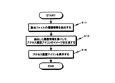
図2には、アクセス管理モジュールが実行する処理手順をフローチャートの形式で図解している。以下、このフローチャートに従って説明する。
【0074】
アクセス管理モジュールは、ファイル・アイコンに対する所定のイベントが発生したことに応答して起動する。ここで言う所定のイベントには、例えば、デスクトップ上に新たにファイル・アイコンが出現したことや、デスクトップ上でマウス・カーソルがある特定のファイル・アイコン上に置かれたことなどが挙げられる。
【0075】
アクセス管理モジュールは、まず、ファイル・システム14が管理する履歴情報(前述)を検索して、該当するファイルに関するアクセス履歴を抽出する(ステップS11)。
【0076】
次いで、抽出されたアクセス履歴情報を基に、アクセス履歴を視覚的に表現したアクセス履歴アイコンのイメージを生成する(ステップS12)。
【0077】
アクセス履歴アイコンは、ファイルに対するアクセス履歴を時系列的に表現し、且つ、ファイルへの参照や変更などのアクセス履歴や、アクセス頻度の時間的な変動パターンなどを、目視で把握できる形態であることが好ましい。
【0078】
図3には、本実施例に係るアクセス履歴アイコンのイメージを図解している。図示の通り、このアクセス履歴アイコンは、水平軸は時間軸に設定した矩形形状のイメージである。また、このアイコン・イメージの時間軸よりも上半分はファイルの変更履歴の表示に割り当てられ、下半分はファイルの参照履歴の表示に割り当てられている。そして、ファイル・システムから抽出された履歴情報を参照して、ファイルの変更や参照が実行された各時刻に対応する位置に、変更履歴マーク及び/又は参照履歴マークを付す。
【0079】
但し、アクセス履歴アイコンの表現形態は、図3に示したものに必ずしも限定されず、アクセス履歴を時間軸上で表示した形式のアイコンであり、ファイルの参照や変更などのアクセス履歴やアクセス頻度の時間的な変動パターンを目視で把握できる形態であれば何でもよい。例えば、アイコンの水平軸ではなく垂直軸を時間軸として設定してもよい。また、時間軸の縮尺や、アイコン上に表示される期間は任意であり、ユーザ・プログラマブルであってもよい。
【0080】
このようなアクセス履歴アイコンのイメージを生成すると、次いで、このアイコン・イメージを、デスクトップ上の該当するファイル・アイコンの近傍に表示する(ステップS13)。
【0081】
アクセス履歴アイコンの表示形態は、デスクトップ画面上である特定のファイル・アイコンにマウス・カーソルが置かれたときにポップアップ表示するようにしても、あるいは、ファイル・アイコンをデスクトップ上に表示する期間中はアクセス履歴アイコンを常時表示させるようにしてもよい。
【0082】
図4には、関連するファイル・アイコンにマウス・カーソルが置かれたときに,アクセス履歴アイコンがポップアップ表示される様子を図解している。
【0083】
コンピュータのユーザは、デスクトップ上でマウス・カーソルを移動させていき(図4(a)を参照のこと)、特定のファイル”holosig.pdf”のアイコン表示領域にカーソルが突入したことに応答して、アクセス管理モジュールが起動する。そして、このファイルに関するアクセス履歴を描写したアクセス履歴アイコンがファイル・アイコン近傍に出現する(図4(b)を参照のこと)。
【0084】
また、図5には、デスクトップ上(若しくは、Windows95/98における「エクスプローラ」ウィンドウ内)で一覧表示されたファイル・アイコンの各々にアクセス履歴アイコンが併置されている様子を図解している。
【0085】
図4に示す場合のように、アクセス履歴アイコンが必要なときのみポップアップ表示される場合には、アクセス履歴アイコンをファイル・アイコン本体の上に重畳表示するようにしてもよい。これに対し、図5に示す場合のように、アクセス履歴アイコンが常設される場合には、アクセス履歴アイコンは、ファイル・アイコン本体を覆い隠さない位置に配設されることが、ファイル・アイコン自体を視認する上で好ましい。
【0086】
要するに、本実施形態によれば、コンピュータのユーザは、ファイル・アイコンをデスクトップ画面上で視認するだけでなく、ファイルに対する参照履歴や変更履歴やその時間的な変動パターンを、一見して直感的に把握することができる。例えば、「このファイルは1週間前から頻繁に参照されるようになった」等のようなファイルに関わる情報を視覚的且つ簡便に得ることにより、ファイル・アクセスのための有効な手掛かりにすることができる。
【0087】
さらに、本実施形態に係るアクセス履歴アイコンの応用形態として、アクセス履歴アイコンの矩形表示領域をマウス・カーソルで探索して、所望の変更履歴マークをクリックすることで、該当する日時に変更されたファイルを呼び出すことができる。図6には、この応用例に関するデスクトップ画面上における一連の操作手順を図解している。
【0088】
デスクトップ画面上でマウス・カーソルを操作し、ある特定のファイル”holosig.pdf”のアイコン領域上にカーソルが突入したことに応答して、アイコン管理モジュールが起動して、この結果、このファイルに関するアクセス履歴アイコンが生成され、ファイル・アイコン上に重畳表示される(図6(a)を参照のこと)。
【0089】
次いで、このアクセス履歴アイコンの矩形表示領域内でマウス・カーソルを操作すると、カーソル位置に対応する日時情報がポップアップ表示される(図6(b)を参照のこと)。
【0090】
そして、アクセス履歴アイコンの矩形表示領域内で、特定の変更履歴マーク及び/又は参照履歴マークの上でマウスをクリックすると、さらに、ファイル・アイコンが最全面にポップアップ表示される(図6(c)を参照のこと)。ポップアップされたファイル・アイコンは、当該ファイルに関する現在のエンティティではなく、クリック操作された変更履歴マークに対応するする日時におけるファイル・エンティティであると理解されたい。
【0091】
さらに、このポップアップ表示されたファイル・アイコンを、マウスでドラッグ操作することにより、このファイル・エンティティをアイコンとしてデスクトップから取り出すことができる(図6(c)を参照のこと)。
【0092】
但し、上述したような応用例の場合、単一のファイル名に対して複数のファイル・エンティティが存在することになり、ファイル数や総ファイル・サイズが膨大となり、ファイル空間への負荷が過大となってしまう。したがって、このような場合、各々の変更ファイル・エンティティ全体を保存するのではなく、各変更ファイル間の差分のみを記録することにより、ファイル・サイズを圧縮するなどの工夫を採り入れることが好ましいであろう。
【0093】
なお、本出願人に既に譲渡されている特願平11−108535号の明細書には、生成されるファイルを時間の経過と対応付けて記憶することができる情報処理装置及び情報処理方法について開示している。
【0094】
次に、分散コンピューティング環境に置かれたコンピュータ・システムに対して本発明を適用した第2の実施形態について説明する。
【0095】
図7には、本発明に実施に供される、分散環境のネットワーク・コンピューティング・システム100の構成を模式的に示している。本実施例では、ネットワーク101はインターネットのような広域的且つオープンなネットワークであるとする。インターネット101上では、無数のコンピュータ・システムが、TCP/IP(Transmission Control Protocol/Internet Protocol)プロトコルに従って相互接続されている。
【0096】
また、インターネット101上には、WWW(World Wide Web)と呼ばれる、情報資源の提供を行うための資源提供空間が構築されている。
【0097】
WWW資源空間上で提供される資源オブジェクトは、HTML(Hyper Text Markup Language)形式で記述されたハイパーテキスト・ドキュメントである。すなわち、WWWは、各HTMLドキュメント相互間のリンク関係によって形成されたハイパーリンク構造の資源空間を提供するものである。インターネット上では、HTMLドキュメントを始めとする各種の資源オブジェクトは、URL(Uniform Resource Locator)形式で記述される一種のアドレス情報によって識別される。
【0098】
インターネット101上の一部のコンピュータは、WWWサーバ110として動作し、資源オブジェクトとしてのHTMLドキュメントの提供サービスを行う。また、その他の一部のコンピュータは、WWW資源オブジェクトを要求するWWWクライアント120として動作する。WWW空間では、サーバ−クライアント間では、HTTP(Hyper Text Transfer Protocol)プロトコルに従って資源アクセスが行われる(周知)。
【0099】
WWWサーバ110とは、実際には、サーバ用アプリケーションを実行する汎用コンピュータ・システムで構成される。また、WWWクライアント120は、実際には、「WWWブラウザ」と呼ばれる、資源探索を代行する「ユーザ・エージェント」を起動した汎用コンピュータ・システムで構成される。
【0100】
WWWブラウザは、WWWクライアント120のユーザが所望のWWWページに対するアクセス要求として、URL文字列をキー入力するための「場所ボックス」を備えている。WWWブラウザは、入力されたURLに従って、WWW空間上の特定のWWWサーバ110にアクセスして、要求されたWWW資源オブジェクトすなわちHTMLドキュメントの取得を試みる。そして、WWWブラウザは、ダウンロードしたHTMLドキュメントを解析して、WWWページ(「ホームページ」とも言う)画面を生成する。
【0101】
また、WWWブラウザは、WWWページ中で、他のWWW資源オブジェクトへのリンク情報が埋め込まれた文字列や画像などの表示オブジェクトを、「アンカー」としてホットスポット表示する。ユーザは、これらアンカーのクリックという直感的な操作のみによって、リンク先に対するアクセス要求を発行し、以ってWWW資源空間を自在に探索することができる。
【0102】
本発明を好適に実現するためには、WWWサーバ110は、WWW資源オブジェクトとしてのHTMLドキュメントすなわちWWWページを所有し且つインターネット101上で提供する以外に、さらに、各WWWページに対するアクセスの履歴情報を記録する機能を具備することが好ましい。履歴情報には、アクセス時刻とアクセス属性(すなわち単なる参照か、又は変更か)が含まれる。図示の例では、1999年6月19日6時20分30秒に、ディレクトリ”home”中の”rekimoto.doc”に書き込みアクセスしたことと、同日6時21分56秒に、ディレクトリ”home”中のファイル”abc.c”に読み出しアクセスしたことが、WWW資源のアクセス履歴情報として記録されている。
【0103】
現在普及しているWWWサーバ用のアプリケーションは、基本的に、WWWページに対するアクセス履歴を記録する機能を標準装備している。
【0104】
図8には、WWWブラウザがWWWページ上の各参照情報についてのアクセス履歴情報を取得するために、WWWクライアント120とWWWサーバ110の間で行われる連携的動作を模式的に図解している。
【0105】
WWWクライアントのユーザは、WWWブラウザ画面上の場所ボックスに所望のWWWページに関するURLをキー入力するか、あるいは、WWWブラウザ画面に表示されたWWWページ中の所望のアンカーをマウスでクリックすることにより、WWWページの取得を要求する。
【0106】
一方、ページ要求メッセージを受信したWWWサーバ110側では、まず、URL文字列の記述に従って、自己のローカル・ディスクから該当する資源オブジェクトすなわちWWWページを取り出す。但し、該当するWWWページは、必ずしもページ要求メッセージを受け取ったWWWサーバ110自身が所有する必要はなく、WWWサーバ110がさらに別のWWWサーバ(図示しない)に対してWWWページの提供要求を発行してもよい。
【0107】
次いで、WWWサーバ110は、自己が管理するWWWページに関する履歴情報(前述)を検索して、取得したWWWページ内に埋め込まれた各リンク先に関するアクセス履歴を抽出する。そして、WWWページを構成するHTMLソース・コード中で、各リンク先のアンカー表示を規定した部分に、アクセス履歴アイコンを表示するためのスクリプトを埋めこむ。なお、スクリプトとは、ソフトウェアに実行させる処理手順をテキスト形式で記述したものであり、通常、アプリケーションやOS上で、エンド・ユーザが制御できる操作手順を組み合わせた一連の処理を自動化するために利用される。
【0108】
アクセス履歴アイコンは、リンク先に対するアクセス履歴を時系列的に表現し、且つ、このアイコンを一見しただけでリンク先への参照や変更などの履歴を時系列的な変動パターンとして把握できる表現形態であることが好ましい。例えば、前述の図3に示すようなアイコン・イメージでよい。すなわち、アクセス履歴アイコンは、水平軸は時間軸に設定した矩形形状のイメージであり、時間軸よりも上半分はWWWページの変更履歴の表示に割り当てられ、下半分はWWWページの参照履歴の表示に割り当てられる。そして、履歴情報を参照して、ファイルの変更や参照が実行された各時刻に対応する位置に、変更履歴マーク及び参照履歴マークを付す。
【0109】
また、アクセス履歴アイコンを表示するためのスクリプトは、例えば、JavaScriptやJScriptのようなスクリプト言語で記述することができる。履歴情報を基にアイコン表示用のスクリプトを自動生成し、且つ、これをHTMLソースコード中の該当個所に埋め込むことは、当業界における周知技術を用いて実現可能である。
【0110】
アクセス履歴アイコン表示用のスクリプトが埋め込まれたWWWページは、要求元のWWWクライアント120に返信される。
【0111】
WWWクライアント120のWWWブラウザは、受信したWWWページを解析して、画面表示する。WWWブラウザによるこのWWWページ表示画面では、アクセス履歴アイコンを用いた、本発明に固有のサービスを提供することができる。
【0112】
アクセス履歴アイコンの表示形態は、WWWページ表示画面上でアンカーにマウス・カーソルが置かれたときにポップアップ表示するようにしても、あるいは、WWWページを画面表示している期間中は同ページ中の各アンカーに対してアクセス履歴アイコンを常時表示させるようにしてもよい。
【0113】
図9には、特定のアンカーにマウス・カーソルが置かれたときに,アクセス履歴アイコンがポップアップ表示される様子を図解している。
【0114】
但し、同図に示す例は、WWW上の電子掲示板システム(Bulletin Board System:BBS)に応用した例である。電子掲示板システムでは、通常、話題毎にアンカーが割り当てられている(例えば、WWW上の有名な電子掲示板システムの1つであるYahoo掲示板”message.yahoo.co.jp”では、この形式が採用されている)。利用者は、話題の名前を基にアンカーを選択してリンクを辿ることができる。
【0115】
WWWクライアントのユーザは、デスクトップ上でマウス・カーソルを移動させていき(図9(a)を参照のこと)、ある特定の話題”000000000000” に相当するアンカーにカーソルが突入したことに応答して、埋め込まれたスクリプトが起動して、このファイルに関するアクセス履歴を描写したアクセス履歴アイコンがファイル・アイコン近傍に出現する(図9(b)を参照のこと)。
【0116】
また、図10は、WWWページを画面表示している期間中は同ページ中の各アンカーに対してアクセス履歴アイコンを常時表示させる様子を図解している。但し、図9の場合と同様に、WWW上の電子掲示板システム(Bulletin Board System:BBS)に応用した例である。
【0117】
従来は、「最近活発に議論されている情報が知りたい」、あるいは、「最近みんなが興味を持っている話題についての議論を読みたい」といった、WWW上の多数の利用者(議論の参加者)についての傾向すなわち参照履歴に依存した情報探索・情報選択を行うことが困難であった。これに対し、上述の図9及び図10に示す方式によれば、話題に該当するアンカーの近傍に履歴情報がアイコン形式で表示されているので、各話題がどの程度の頻度で参照及び/又は更新されているかといった時系列的な変動パターンを、一見して把握することができる。
【0118】
本実施形態に係る方式は、WWW資源空間上で提供されているその他の種々のサービスにも適用することかできる。例えば、企業情報に関するWWWページから製品に関するWWWページを辿る場合にも、人気商品や商品の鮮度をアクセス履歴アイコンの表示を手掛かりにして、視認することができる。
【0119】
要するに、本実施形態によれば、WWWクライアントのユーザは、アンカーが示す参照情報をWWWブラウザ画面上で視認するだけでなく、アンカーが示すリンク先のWWWページに対する参照履歴や変更履歴を一見しただけで直感的且つ精度よく把握することができる。例えば、「このWWWページは3時間毎に更新されている」等のような更新履歴を視覚的且つ瞬時に得ることにより、WWW資源空間の探索(すなわち「ネット・サーフィン」)のための有効な手掛かりにすることができる。
【0120】
次に、デジタル・データ放送方式のテレビ番組に対して本発明を適用した第3の実施形態について説明する。
【0121】
図11には、本発明の実施に供されるテレビ放送システム200の構成を模式的に示している。
【0122】
図11に示すように、テレビ放送システム200は、放送サービスを提供する放送局(Broadcast Server)210と、放送コンテンツを受信する受信局(Receiver/Decoder)220とで構成される。放送局210は地上に1基以上存在する。また、受信局220は、一般家庭などに相当し、実際には地上に無数散在する。図11では、図面の簡素化のため。放送局210及び受信局220ともに1基のみ描写する。本発明を実現する上で、放送波は地上波又は衛星波を区別しない。また、配信形態は、無線でなく有線であっても構わない。
【0123】
データ放送用のデジタル・データは、放送番組本編であるリアルタイムの映像情報及び音声情報(以下、「リアルタイムAVデータ」とも呼ぶ)と多重化され、所定フォーマットに従った放送波として、放送局210から配信される。
【0124】
一方の受信局220側では、受信された放送波は、選局され、デジタル変調された後、リアルタイムAVデータと、データ放送用のデータとに分離される。リアルタイムAVデータからは、元の放送番組本編に関する映像及び音声が組み立てられる。また、データ放送用のデータは、コンピュータ処理が施され、データ放送表示用のデータとして組立てられる。
【0125】
そして、テレビ画面上には、放送番組本編に関する映像と、データ放送によって生成される表示データとが重畳表示される。
【0126】
データ放送用のデータには、一般に、EPG(Electric Program Guide:電子番組ガイドなどの放送番組の放送スケジュールや番組名などの提示情報の他、VTRへの録画予約などの機能が含まれている。
【0127】
本実施形態では、データ放送用データのコンテンツの1つとして、各番組が得た視聴率データを組み込むこととした。この結果、テレビ画面上には、放送番組本編の他に、複数の番組(チャンネル)がアイコン形式で表示されるとともに、各アイコンには過去一定期間における視聴率の変動パターンが、アクセス履歴アイコン(図3を参照のこと)の形式で提示される。
【0128】
各番組の視聴率に関しては、放送局210が独自に多数の視聴者モニタを設定して各モニタからの検出結果を利用することができる。あるいは、放送局210外の視聴率調査会社から入手した視聴率データを利用しても構わない。各放送番組の視聴率は、放送コンテンツという資源オブジェクトに対するアクセス件数若しくはアクセス頻度を指示する値である。また、視聴率は、時々刻々変動する時系列データという性質も持つ。
【0129】
図12には、本実施例に係るデータ放送用受信画像の画面表示を図解している。同図に示すように、テレビ画面は、番組本編に係る映像表示領域と、データ放送用の画像表示領域とに分割される。同図の例では、データ放送用画像表示領域には、複数のチャンネル選択ボタンが配設されている。そして、各ボタン上には、各チャンネルで放送中の番組に関する過去一定期間における視聴率の変動パターンを表したアクセス履歴アイコンが併置されている。
【0130】
視聴者は、現在放送されている番組一覧の中から最も人気のあるものを視認でき、容易にチャンネル選択することができる。
【0131】
なお、現在、日本国内では、ARIB(Association of Radio Industries and Bussinesses:電波産業会)を中心として、デジタル衛星データ放送の標準化作業が進められている。本実施形態に係るデータ放送用データは、この標準化作業により採用が検討されているXML(eXtensible Markup Language)のようなマークアップ記述言語を用いて記述することも可能である。
【0132】
《追補》
以上、特定の実施例を参照しながら、本発明について詳解してきた。しかしながら、本発明の要旨を逸脱しない範囲で当業者が該実施例の修正や代用を成し得ることは自明である。すなわち、例示という形態で本発明を開示してきたのであり、限定的に解釈されるべきではない。本発明の要旨を判断するためには、冒頭に記載した特許請求の範囲の欄を参酌すべきである。
【0133】
【発明の効果】
以上詳記したように、本発明によれば、コンピュータ上で取り扱われる資源オブジェクトに対するユーザのアクセス状況を、コンピュータのデスクトップ画面上で容易且つ直感的に視認することができる、優れたアクセス状況の管理技術を提供することができる。
【0134】
また、本発明によれば、各資源オブジェクトに関する参照状況と更新状況に分けて、コンピュータのデスクトップ画面上で容易且つ直感的に視認することができる、優れたアクセス状況の管理技術を提供することができる。
【0135】
本発明によれば、コンピュータ上で取り扱われる各資源オブジェクト(コンピュータ・ファイルやWWWページなど)に対する参照履歴や更新履歴が逐次記録される。さらに、このようなアクセス履歴情報を視覚化した表示オブジェクトすなわち「アクセス履歴アイコン」を生成して、コンピュータのデスクトップ画面上の対応するファイル・アイコンや、WWWページ画面上の対応するアンカーの近傍に表示することができる。例えば、該当する資源オブジェクトに対するアクセス・イベントを時間軸に沿って表示したイメージを有する。また、該イメージは、アクセスが変更と参照の場合に分けて表示するようにしてもよい。
【0136】
この結果、コンピュータのユーザは、各資源オブジェクトの参照履歴や更新履歴など、過去一定期間についてのアクセス頻度の変動パターンを、視覚的に且つ直感的に把握することができ、ファイルやWWWページを取捨選択する重要な手掛かりとすることができる。
【図面の簡単な説明】
【図1】本発明の実現に供されるスタンドアロン型コンピュータ10の構成を模式的に示した機能ブロック図である。
【図2】アクセス管理モジュールが実行する処理手順を示したフローチャートである。
【図3】本実施例に係るアクセス履歴アイコンのイメージを図解したものである。
【図4】特定のファイル・アイコンにマウス・カーソルが置かれたときに,アクセス履歴アイコンがポップアップ表示される様子を図解したものである。
【図5】デスクトップ上(若しくは、Windows95/98における「エクスプローラ」ウィンドウ内)で一覧表示されたファイル・アイコンの各々にアクセス履歴アイコンが併置されている様子を図解したものである。
【図6】アクセス履歴アイコンの矩形表示領域をマウス・カーソルで探索して、所望の変更履歴マークをクリックすることで、該当する日時に変更されたファイルを呼び出すための、デスクトップ画面上での一連の操作手順を図解したものである。
【図7】本発明に実施に供される、分散環境のネットワーク・コンピューティング・システム100の構成を模式的に示した図である。
【図8】WWWブラウザがWWW資源オブジェクトについてのアクセス履歴情報を取得するために、WWWクライアント120とWWWサーバ110の間で行われる連携的動作を模式的に図解したものである。
【図9】WWW上の電子掲示板システム(Bulletin Board System:BBS)に本発明を適用した例を示した図であり、より具体的には、特定のアンカーにマウス・カーソルが置かれたときに、アクセス履歴アイコンがポップアップ表示される様子を図解したものである。
【図10】WWW上の電子掲示板システム(Bulletin Board System:BBS)に本発明を適用した例を示した図であり、より具体的には、WWWページを画面表示している期間中は同ページ中の各アンカーに対してアクセス履歴アイコンを常時表示させる様子を図解したものである。
【図11】本発明の実施に供されるテレビ放送システム200の構成を模式的に示した図である。
【図12】本発明の実施例に係るデータ放送用テレビ番組の受信画像を図解したものである。
【符号の説明】
10…コンピュータ・システム
11…アプリケーション実行部
12…ユーザ・インターフェース
12A…キーボード,12B…マウス,12C…ディスプレイ
13…メモリ・システム,14…ファイル・システム
15…ストレージ・システム,16…ネットワーク・システム
100…ネットワーク・コンピューティング・システム
101…インターネット
120…WWWサーバ,130…WWWクライアント
200…テレビ放送システム
210…放送局,220…受信局(一般家庭)[0001]
BACKGROUND OF THE INVENTION
The present invention relates to a technology for managing various resource objects handled on a computer system, and more particularly to a technology for managing a user access status to each resource object.
[0002]
More particularly, the present invention relates to an access status management technique for visually confirming a user's access status to a resource object handled on a computer on a desktop screen of the computer, and further, a reference status and update for each resource object. The present invention relates to an access status management technique that can be visually recognized according to the situation.
[0003]
[Prior art]
With the recent rapid progress in the information technology (IT) field, various general-purpose computer systems such as workstations and personal computers have been developed and manufactured, and are widely used in research institutions such as universities, corporate offices, and general households. is doing.
[0004]
On this type of computer system, various resource objects such as sound and images can be digitized in addition to text format document files, and can be handled uniformly in a predetermined file format.
[0005]
In addition, recent general-purpose computer systems are mainly provided with a bitmap display function (that is, a function for drawing a display in units of pixels) by improving the computing power of a processor or strengthening a video subsystem. Yes. It is also well known that the operating system (OS) supports a bitmap display format and incorporates a graphic-based GUI (Graphical User Interface) instead of a character-based DOS screen, that is, a CUI (Character User Interface). It has become idiomatic.
[0006]
Under this GUI environment, a desktop simulating a computer system and countless icons are prepared on the display screen.
[0007]
Here, the “desktop” is a screen on which a user performs work, and is a background on which display objects such as icons and windows are placed.
[0008]
An “icon” is a small picture representing a resource object that can be used on a computer system, and is displayed on a desktop or a window in the desktop. An icon is a symbol that embodies resource objects such as applications, disk drives, folders (directories), and files on the desktop.
[0009]
A “window” is a frame displayed on the desktop in order to display an object. Windows are standardized in the industry and have a window title bar and window border as basic components. The title bar is a column for displaying the title of the corresponding window, and the information currently displayed in the window, that is, the resource object entity can be identified by this title.
[0010]
On the desktop provided by such a GUI, all resource objects handled on the computer system are represented as icons. The processing for each resource object is realized by an intuitive operation using the mouse, such as click, drag, and drop.
[0011]
For example, on a desktop screen provided by an OS such as Windows 95/98 or an “Explorer” window opened on the desktop screen, an icon representing a processable file, folder, or application is displayed.
[0012]
In addition, with recent improvements in information and communication technology, “network computing” is rapidly spreading. That is, by interconnecting a plurality of computer systems via a network, resource objects such as files owned by each system can be managed efficiently and flexibly. That is, on the network, the work of sharing and distributing files between systems is suitably realized.
[0013]
The term “network” as used herein refers to a communication network for transmitting data between computers, such as a local area network such as a LAN (Local Area Network), as a result of interconnection between servers. There is a wide variety of “Internet” that has become a huge global network. In particular, recently, the use of the Internet has progressed rapidly, and the development of technology related to the Internet is remarkable.
[0014]
On the Internet, a number of resource providing services such as WWW (World Wide Web) are disclosed. WWW is a wide area information retrieval system that provides a resource space in which a hyperlink structure is formed by link relationships between resource objects described in HTML (Hyper Text Markup Language) format. The WWW server and the WWW client requesting the provision are provided, and resource access is performed between the server and the client according to the HTTP (Hyper Text Transfer Protocol) protocol (well-known).
[0015]
The WWW server is actually composed of a general-purpose computer system that executes server applications. The WWW client is actually composed of a general-purpose computer system that activates a “user agent” acting as a resource search, called a “WWW browser”.
[0016]
Each resource object on the WWW resource space is specified by a unique object identifier described in the format of URL (Uniform Resource Locator). On the WWW client side, a character string of a URL indicating a desired resource is keyed into a location box on the WWW browser screen to make an access request to the resource object. Alternatively, the access request to the resource object can also be made by a user interface operation of clicking the anchor in which the URL of the link destination (that is, reference information) in the WWW page is embedded with the mouse. In other words, the WWW browser has an advanced GUI, and the user can freely search between a plurality of WWW pages only by an intuitive operation of clicking an anchor (well known).
[0017]
The anchor on the WWW page screen is, for example, a character string displayed as a hot spot or an icon.
[0018]
[Problems to be solved by the invention]
By the way, in the world of computers and the Internet, data related to the frequency of use of resource objects such as access history is an important clue for managing resource space. The access history is time-series data that changes every moment.
[0019]
For example, infrequently used data and files imply that their utility value and importance are low, and may even be useless enough to free up the storage capacity of the hard disk. If the file is large, such as graphic data or a large-scale application, the burden on the hard disk is excessive. In addition, in a file shared through a network, a file with a small number of references implies that it is unnecessary because it is of low interest among information sharers. Files that are used infrequently are not worth referencing, or even subject to data compression, saving, or discarding.
[0020]
Contrary to this, it is implied that frequently used data and files have high utility value and importance. In addition, among files shared through a network, a file with a high reference count implies that the content stored in the file is meaningful, and is a clue for information search for other users. Also, if data and files that are used frequently are saved or discarded, the burden required for recovery is excessive.
[0021]
For example, when the resource object is a “document” or “book” in the real world, a trace of use naturally remains, which clearly indicates the frequency of use. Well-referenced meaningful books are “dirty”, and often folded pages are “folded”. Such a trace becomes an important clue when selecting documents and books.
[0022]
On the other hand, even if the resource object is a virtual “document” file that exists in the computer world, the access history can be an important clue in selecting a document.
[0023]
However, there is no natural trace of use in this type of virtual document file. For example, on a desktop screen provided by an OS such as Windows 95/98, new files, old files, frequently updated files, and files that are only referenced and not updated are displayed as uniform icons only. Not. Each icon has a different pattern, but this is for identifying each file (that is, the icon itself is a substitute for the file name) and does not reflect the access status. In short, the access status for each file cannot be confirmed at a glance on the desktop screen.
[0024]
On the WWW browser screen, resource objects provided on the WWW resource space, that is, WWW pages, are displayed, but link information to other WWW pages appears in the form of anchors (described above). This anchor is displayed as a hot spot in order to distinguish it from other display objects that do not include link information. Furthermore, an anchor that has been traced once is displayed in a color different from that of other anchors, thereby improving the visibility regarding the access history.
[0025]
By considering the color coding of the anchor, the WWW user can identify a new WWW page or a frequently accessed WWW page with a certain degree of visibility. However, since the color coding of the anchor depends on the data recorded on the local file of the WWW user, it cannot be used by other WWW users existing on the WWW resource space. In addition, almost no specific information such as recent access frequency and update frequency regarding a specific WWW page is provided at present.
[0026]
Some WWW pages have access counters (known). The counter is incremented by one each time someone accesses the page. By looking at the value of this counter, the access status to the page can be grasped to some extent. However, the management method using the access counter has the following problems. That is,
[0027]
(1) The counter value is the cumulative number of accesses starting from a certain date, and cannot indicate an access pattern (access frequency by day of the week, time, etc.).
(2) The count start date varies from page to page, and the true number of accesses cannot be grasped simply by looking at the counter value. In other words, it must be conscious of the matter of counting from when it is not intuitive and cannot be understood at a glance.
(3) The counter is installed in the page and cannot be confirmed by the user before referring to the page, that is, before following the link. Therefore, it is not possible to provide WWW navigation that preferentially traces the most frequently updated link from among a plurality of links.
[0028]
Also, in the Internet industry, when a new anchor is added on a WWW page, there is a convention that icons such as “new” are juxtaposed with the anchor. However, the criterion of “new”, that is, a new one is unknown (it depends on the judgment of each WWW page creator, and the criterion is considered to be different), and is somewhat lacking in reliability. In addition, the “new” icon is meaningless when it is desired to know the reference (access) frequency rather than the page update.
[0029]
The present invention takes into account the technical problems as described above, and its purpose is to easily and intuitively visually recognize a user's access status to a resource object handled on a computer on a desktop screen of the computer. It is to provide excellent access status management technology.
[0030]
It is a further object of the present invention to provide an excellent access status management technique that can be easily and intuitively recognized on the desktop screen of a computer, divided into a reference status and an update status regarding each resource object. is there.
[0031]
[Means for Solving the Problems]
The present invention has been made in view of the above problems, and a first aspect thereof is a method or apparatus for presenting an access history related to a resource object on a computer screen,
(A) a step or means for sequentially recording access history of resource objects;
(B) a step or means for generating an access history icon representing an access history related to the resource object in a time-series manner;
(C) displaying or displaying the generated access history icon on the computer screen in association with the resource object icon;
An access history presentation method or device comprising:
[0032]
In the access history presentation method or apparatus according to the first aspect of the present invention, the access history icon is configured by a time axis and a mark indicating each access history arranged at a corresponding position on the time axis. It may be. The computer user can easily and intuitively grasp the fluctuation pattern of the usage frequency with the passage of time for the resource object by simply looking at the access history icon in such an expression form.
[0033]
Further, the access history icon distinguishes whether each access history is a reference or a change to the resource object, and arranges a reference history mark and / or a change history mark at a corresponding position on the time axis. You may make it comprise.
[0034]
In addition, the access history presentation method or apparatus further provides a resource object entity corresponding to the change history mark in response to the user selecting one change history mark in the access history icon. Steps or means may be provided.
[0035]
In addition, at least one of the step or means (b) and / or the step or means (c) has entered the user's interest in the icon display area of one resource object displayed on the computer screen. It may be activated in response to. The user's interest can be measured, for example, according to the display position of a cursor that freely moves by a mouse operation or the like on a computer screen.
[0036]
Alternatively, at least one of the step or means (b) or step or means (c) may be activated in response to an icon of a resource object being displayed on the computer screen. .
[0037]
The resource object is, for example, a file in a predetermined format that can be processed on a computer.
[0038]
The second aspect of the present invention is a resource providing method or apparatus for providing a resource object including reference information to another resource object,
(A) a step or means for sequentially recording an access history for each resource object;
(B) a step or means for generating an instruction to display an access history icon representing an access history related to the resource object in a time series;
(C) attaching the instruction generated by said step or means (b) to the reference information to the resource object;
A resource providing method or apparatus comprising:
[0039]
In the resource providing method or apparatus according to the second aspect of the present invention, the resource providing method or apparatus may be configured with a time axis and marks indicating access histories arranged at corresponding positions on the time axis. The user who receives the resource can easily and intuitively grasp the fluctuation pattern of the usage frequency with the passage of time for the resource object by simply looking at the access history icon in such an expression form.
[0040]
Further, the access history icon distinguishes whether each access history is a reference or a change to the resource object, and arranges a reference history mark and / or a change history mark at a corresponding position on the time axis. You may make it comprise.
[0041]
Further, the command for displaying the access history icon generated in the step or means (b) responds to the user's interest entering a certain reference information on the computer screen displaying the resource object. Then, it may be specified to display an access history icon for the resource object referred to by the reference information.
[0042]
Alternatively, the instruction to display the access history icon generated in the step or means (b) is for the resource object to which the reference information refers in response to displaying the reference information on the computer screen. It may be specified that an access history icon is displayed.
[0043]
Further, at least one of the steps (b) and (c) may be activated in response to a request for provision of a resource object.
[0044]
The resource object may be a document file described in a markup description language, and the command generated in the step or means (b) may be a script described in a script language.
[0045]
According to a third aspect of the present invention, there is provided, in a tangible and computer-readable form, a computer program for causing a computer to execute processing for presenting information to be displayed on an access history related to a resource object on a computer screen. A program providing medium to be provided, the computer program comprising:
(A) sequentially recording the access history of the resource object;
(B) generating an access history icon representing an access history related to the resource object in a time-series manner;
(C) displaying the generated access history icon on the computer screen in association with the resource object icon;
A program providing medium characterized by comprising:
[0046]
According to a fourth aspect of the present invention, there is provided a computer program for executing a resource providing process for providing a resource object including reference information to another resource object on a computer in a tangible and computer-readable format. A program providing medium provided by the computer program, wherein the computer program is:
(A) sequentially recording an access history for each resource object;
(B) generating an instruction for displaying an access history icon representing an access history related to the resource object in a time series;
(C) attaching the instruction generated in step (b) to the reference information to the resource object;
A program providing medium characterized by comprising:
[0047]
[Action]
According to the present invention, the reference history and update history for each resource object handled on the computer are sequentially recorded. The resource object referred to here is, for example, a file such as a document, sound, or image handled in a predetermined format on a computer. Another example of the resource object is a WWW (World WideWeb) page (HTML (H y per text M arcup Language) document).
[0048]
Further, according to the present invention, a display object that visualizes such access history information, that is, an access history icon is generated, and a corresponding icon on a computer desktop screen or a corresponding anchor on a WWW page screen is generated. Can be displayed in the vicinity of. The access history icon has, for example, an image in which access events for the corresponding resource object are displayed along the time axis. Further, the image may be displayed separately when the access is a change and a reference.
[0049]
As a result, the computer user can visually and intuitively grasp the reference history and update history of each resource object as a time-series fluctuation pattern, which is an important clue for selecting files and pages. Can be.
[0050]
The program providing medium according to each of the third and fourth aspects of the present invention provides a computer program in a tangible and computer-readable form, for example, to a general-purpose computer system capable of executing various program codes. It is a medium to The providing medium is a removable and portable storage medium such as a CD (Compact Disc), an FD (Floppy Disc), and an MO (Magneto-Optical disc), or a network (the network is wireless or wired, or terrestrial or satellite) There is no particular limitation on the form of the transmission medium, such as a wave of any kind.
[0051]
Such a program providing medium defines a structural or functional cooperative relationship between a computer program and a providing medium for realizing a function of a predetermined computer program on a computer system. . In other words, by installing a predetermined computer program in the computer system via the program providing medium according to each of the third and fourth aspects of the present invention, a cooperative action is exhibited on the computer system. The same effects as those of the first and second aspects of the present invention can be obtained.
[0052]
Other objects, features, and advantages of the present invention will become apparent from a more detailed description based on embodiments of the present invention described later and the accompanying drawings.
[0053]
DETAILED DESCRIPTION OF THE INVENTION
Hereinafter, embodiments of the present invention will be described in detail with reference to the drawings.
[0054]
First, a first embodiment in which the present invention is applied to a stand-alone computer system will be described.
[0055]
FIG. 1 is a functional block diagram schematically showing the configuration of a stand-
[0056]
The
[0057]
The
[0058]
The user interface of the present embodiment provides a GUI (Graphical User Interface) environment, and a “desktop” that simulates the
[0059]
The user can use this desktop screen as a work place via the mouse 12B, that is, use the mouse cursor to input a command by an intuitive operation such as click, drag and drop on the display object. it can.
[0060]
The memory system 13 is a functional module for managing a memory space consisting of several tens of MBs to several hundreds of MBs. More specifically, a program code used in the
[0061]
The
[0062]
In order to suitably realize the present invention, the
[0063]
However, in most operating systems for general consumers such as Microsoft Windows 95/98, the actual situation is that the file system does not have a function for recording an access history as a standard feature. For this reason, when implementing the present invention, it is necessary for the implementer to make it by himself.
[0064]
The
[0065]
Further, with this type of portable recording medium, it is possible to move (ie, distribute and distribute) resource objects, that is, files such as programs and data, among a plurality of computer systems. For example, a computer program for realizing the present invention can be installed in the
[0066]
The network system 16 is a functional module for connecting the
[0067]
The
[0068]
A specific example of this type of
[0069]
Next, file access status management realized on the
[0070]
As described above, a resource object such as a file is embodied as an “icon” on the desktop screen. In this embodiment, the “access management module” is activated in conjunction with this icon display, generates an icon image that visualizes the access history based on the access history information about the file, and displays the access history icon. It has a function of displaying in the vicinity of the corresponding file icon.
[0071]
The access history icon is displayed as a pop-up when the mouse cursor is placed on the associated file icon, or the access history icon is always displayed while the file icon is displayed on the desktop. It may be displayed.
[0072]
This “access management module” may be incorporated as a part of another function module such as the
[0073]
FIG. 2 illustrates a processing procedure executed by the access management module in the form of a flowchart. Hereinafter, description will be given according to this flowchart.
[0074]
The access management module is activated in response to the occurrence of a predetermined event for the file icon. The predetermined event mentioned here includes, for example, the appearance of a new file icon on the desktop and the placement of the mouse cursor on a specific file icon on the desktop.
[0075]
The access management module first searches history information (described above) managed by the
[0076]
Next, an image of an access history icon that visually represents the access history is generated based on the extracted access history information (step S12).
[0077]
The access history icon expresses the access history for a file in a time series, and is a form in which the access history such as reference or change to the file, the temporal variation pattern of the access frequency, etc. can be grasped visually. Is preferred.
[0078]
FIG. 3 illustrates an image of an access history icon according to the present embodiment. As shown, this access history icon is a rectangular image with the horizontal axis set to the time axis. Further, the upper half of the time axis of the icon image is assigned to display the file change history, and the lower half is assigned to display the file reference history. Then, referring to the history information extracted from the file system, a change history mark and / or a reference history mark is attached to a position corresponding to each time when the file is changed or referred to.
[0079]
However, the expression form of the access history icon is not necessarily limited to that shown in FIG. 3, and is an icon in a format in which the access history is displayed on the time axis, and the access history and access frequency such as file reference and change are displayed. Any form can be used as long as the temporal variation pattern can be grasped visually. For example, the vertical axis instead of the horizontal axis of the icon may be set as the time axis. The scale of the time axis and the period displayed on the icon are arbitrary and may be user programmable.
[0080]
Once such an access history icon image is generated, this icon image is then displayed in the vicinity of the corresponding file icon on the desktop (step S13).
[0081]
The access history icon may be displayed as a pop-up when the mouse cursor is placed on a specific file icon on the desktop screen, or while the file icon is displayed on the desktop. The access history icon may be always displayed.
[0082]
FIG. 4 illustrates a state in which an access history icon is popped up when the mouse cursor is placed on a related file icon.
[0083]
The computer user moves the mouse cursor on the desktop (see FIG. 4A), and responds to the cursor entering the icon display area of a specific file “holosig.pdf”. The access management module is activated. Then, an access history icon depicting the access history related to this file appears in the vicinity of the file icon (see FIG. 4B).
[0084]
FIG. 5 illustrates a state in which an access history icon is juxtaposed to each of the file icons listed on the desktop (or in the “Explorer” window in Windows 95/98).
[0085]
As in the case shown in FIG. 4, when an access history icon is displayed in a pop-up only when necessary, the access history icon may be superimposed on the file icon body. On the other hand, when the access history icon is permanently installed as shown in FIG. 5, the access history icon may be arranged at a position that does not cover the file icon body. It is preferable for visually recognizing
[0086]
In short, according to the present embodiment, the user of the computer not only visually recognizes the file icon on the desktop screen, but also intuitively at a glance the reference history and change history of the file and its temporal variation pattern. I can grasp it. For example, by obtaining information related to the file such as “This file has been frequently referenced from a week ago” etc., it becomes an effective clue for file access. Can do.
[0087]
Furthermore, as an application form of the access history icon according to the present embodiment, a file that has been changed to the corresponding date and time by searching the rectangular display area of the access history icon with a mouse cursor and clicking the desired change history mark Can be called. FIG. 6 illustrates a series of operation procedures on the desktop screen relating to this application example.
[0088]
In response to the cursor entering the icon area of a specific file “holosig.pdf” by operating the mouse cursor on the desktop screen, the icon management module is started, and as a result, access to this file is performed. A history icon is generated and superimposed on the file icon (see FIG. 6A).
[0089]
Next, when the mouse cursor is operated within the rectangular display area of the access history icon, date and time information corresponding to the cursor position is displayed in a pop-up (see FIG. 6B).
[0090]
When the mouse is clicked on a specific change history mark and / or reference history mark in the rectangular display area of the access history icon, a file icon is further popped up on the entire surface (FIG. 6C). checking). It should be understood that the popped up file icon is not the current entity for the file, but the file entity at the date and time corresponding to the clicked change history mark.
[0091]
Further, by dragging the file icon displayed in the pop-up with the mouse, the file entity can be taken out from the desktop as an icon (see FIG. 6C).
[0092]
However, in the case of the application example as described above, a plurality of file entities exist for a single file name, the number of files and the total file size become enormous, and the load on the file space is excessive. turn into. Therefore, in such a case, instead of saving the entire change file entity, only the difference between each change file is recorded, thereby reducing the file size. The It would be preferable to adopt a device such as compression.
[0093]
The specification of Japanese Patent Application No. 11-108535, which has already been assigned to the present applicant, discloses an information processing apparatus and an information processing method capable of storing a generated file in association with the passage of time. is doing.
[0094]
Next, a second embodiment in which the present invention is applied to a computer system placed in a distributed computing environment will be described.
[0095]
FIG. 7 schematically shows the configuration of a network computing system 100 in a distributed environment that is used in the present invention. In this embodiment, it is assumed that the network 101 is a wide area and open network such as the Internet. A myriad of computer systems are interconnected on the Internet 101 according to a TCP / IP (Transmission Control Protocol / Internet Protocol) protocol.
[0096]
Further, on the Internet 101, a resource providing space called WWW (World Wide Web) is provided for providing information resources.
[0097]
A resource object provided on the WWW resource space is a hypertext document described in an HTML (Hyper Text Markup Language) format. That is, the WWW provides a hyperlink structure resource space formed by a link relationship between HTML documents. On the Internet, various resource objects such as HTML documents are identified by a kind of address information described in a URL (Uniform Resource Locator) format.
[0098]
Some computers on the Internet 101 operate as the WWW server 110 and provide a service for providing an HTML document as a resource object. In addition, some other computers operate as the WWW client 120 that requests the WWW resource object. In the WWW space, resource access is performed between the server and the client according to the HTTP (Hyper Text Transfer Protocol) protocol (well-known).
[0099]
The WWW server 110 is actually composed of a general-purpose computer system that executes server applications. The WWW client 120 is actually configured by a general-purpose computer system that activates a “user agent” acting as a resource search, called a “WWW browser”.
[0100]
The WWW browser includes a “location box” for the user of the WWW client 120 to key-in a URL character string as an access request for a desired WWW page. The WWW browser accesses a specific WWW server 110 in the WWW space according to the input URL, and tries to acquire the requested WWW resource object, that is, an HTML document. Then, the WWW browser analyzes the downloaded HTML document and generates a WWW page (also referred to as “homepage”) screen.
[0101]
In addition, the WWW browser displays a display object such as a character string or an image in which link information to another WWW resource object is embedded in the WWW page as an “anchor” as a hot spot. The user can issue an access request for the link destination only by an intuitive operation of clicking these anchors, and can freely search the WWW resource space.
[0102]
In order to suitably realize the present invention, the WWW server 110 owns an HTML document as a WWW resource object, that is, a WWW page, and provides it on the Internet 101, and also provides access history information for each WWW page. It is preferable to have a recording function. The history information includes an access time and an access attribute (that is, whether it is merely a reference or a change). In the illustrated example, at 6:20:30 on June 19, 1999, a write access was made to “rekimoto.doc” in the directory “home”, and at 6:21:56 on the same day, the directory “home” Read access to the file “abc.c” is recorded as access history information of the WWW resource.
[0103]
An application for a WWW server that is currently popular is basically equipped with a function of recording an access history for a WWW page.
[0104]
FIG. 8 schematically illustrates a cooperative operation performed between the WWW client 120 and the WWW server 110 in order for the WWW browser to acquire access history information for each reference information on the WWW page.
[0105]
The user of the WWW client can key-in the URL related to the desired WWW page in the place box on the WWW browser screen, or click the desired anchor in the WWW page displayed on the WWW browser screen with the mouse. Request acquisition of WWW page.
[0106]
On the other hand, the WWW server 110 that has received the page request message first takes out the corresponding resource object, that is, the WWW page, from its own local disk in accordance with the description of the URL character string. However, the corresponding WWW page is not necessarily owned by the WWW server 110 itself that has received the page request message, and the WWW server 110 issues a request for providing a WWW page to another WWW server (not shown). May be.
[0107]
Next, the WWW server 110 searches the history information (described above) regarding the WWW page managed by the WWW server 110, and extracts the access history regarding each link destination embedded in the acquired WWW page. Then, a script for displaying an access history icon is embedded in a part defining the anchor display of each link destination in the HTML source code constituting the WWW page. A script describes a processing procedure to be executed by software in a text format, and is usually used to automate a series of processing that combines operation procedures that can be controlled by an end user on an application or OS. Is done.
[0108]
The access history icon expresses the access history for the link destination in a time series, and it is an expression that can grasp the history of the reference or change to the link destination as a time series fluctuation pattern at a glance. Preferably there is. For example, an icon image as shown in FIG. 3 may be used. That is, the access history icon is a rectangular image in which the horizontal axis is set to the time axis, the upper half of the time axis is assigned to display the change history of the WWW page, and the lower half is the display of the reference history of the WWW page. Assigned to. Then, with reference to the history information, a change history mark and a reference history mark are attached to the positions corresponding to the respective times when the file is changed or referred to.
[0109]
A script for displaying an access history icon can be described in a script language such as JavaScript or JScript. It is possible to automatically generate a script for displaying an icon based on the history information and embed it in a corresponding place in the HTML source code by using a well-known technique in the industry.
[0110]
The WWW page in which the script for displaying the access history icon is embedded is returned to the requesting WWW client 120.
[0111]
The WWW browser of the WWW client 120 analyzes the received WWW page and displays it on the screen. On this WWW page display screen by the WWW browser, a service unique to the present invention using an access history icon can be provided.
[0112]
The access history icon may be displayed as a pop-up when the mouse cursor is placed on an anchor on the WWW page display screen, or during the period when the WWW page is displayed on the screen. You may make it always display an access history icon with respect to each anchor.
[0113]
FIG. 9 illustrates a state where an access history icon is popped up when the mouse cursor is placed on a specific anchor.
[0114]
However, the example shown in the figure is an example applied to an electronic bulletin board system (Bulletin Board System: BBS) on the WWW. In an electronic bulletin board system, an anchor is usually assigned to each topic (for example, this form is adopted in Yahoo bulletin board "message.yahoo.co.jp" which is one of the famous electronic bulletin board systems on the WWW. ing). The user can follow the link by selecting an anchor based on the topic name.
[0115]
The user of the WWW client moves the mouse cursor on the desktop (see FIG. 9A), and in response to the cursor entering the anchor corresponding to a specific topic “000000000000”. The embedded script is activated, and an access history icon depicting the access history related to this file appears in the vicinity of the file icon (see FIG. 9B).
[0116]
Further, FIG. 10 illustrates a state in which an access history icon is always displayed for each anchor in the page during the period when the WWW page is displayed on the screen. However, as in the case of FIG. 9, this is an example applied to a bulletin board system (BBS) on the WWW.
[0117]
In the past, many users on the WWW (participants in discussions) such as “I want to know information that has been actively discussed recently” or “I want to read discussions on topics that everyone is interested in recently” ), That is, it is difficult to search and select information depending on the reference history. On the other hand, according to the method shown in FIG. 9 and FIG. 10 described above, history information is displayed in the form of an icon in the vicinity of an anchor corresponding to a topic, so how often each topic is referenced and / or It is possible to grasp at a glance a time-series fluctuation pattern such as whether it is updated.
[0118]
The method according to the present embodiment can also be applied to other various services provided on the WWW resource space. For example, when a WWW page related to a product is traced from a WWW page related to company information, the freshness of a popular product or a product can be visually recognized using a display of an access history icon as a clue.
[0119]
In short, according to the present embodiment, the user of the WWW client not only visually recognizes the reference information indicated by the anchor on the WWW browser screen but also at a glance at the reference history and the change history for the linked WWW page indicated by the anchor. Can be grasped intuitively and accurately. For example, by obtaining an update history such as “this WWW page is updated every 3 hours” visually and instantaneously, it is possible to effectively search for a WWW resource space (ie, “net surfing”). It can be a clue.
[0120]
Next, a third embodiment in which the present invention is applied to a digital data broadcasting television program will be described.
[0121]
FIG. 11 schematically shows the configuration of a television broadcast system 200 that is used to implement the present invention.
[0122]
As shown in FIG. 11, the television broadcast system 200 includes a broadcast station 210 that provides a broadcast service, and a receiver station (Receiver / Decoder) 220 that receives broadcast content. One or more broadcast stations 210 exist on the ground. In addition, the receiving stations 220 correspond to ordinary homes and the like, and are actually scattered on the ground. In FIG. 11, for simplification of the drawing. Only one broadcasting station 210 and receiving station 220 are depicted. In realizing the present invention, broadcast waves do not distinguish between ground waves and satellite waves. The distribution form may be wired instead of wireless.
[0123]
Digital data for data broadcasting is multiplexed with real-time video information and audio information (hereinafter also referred to as “real-time AV data”), which is the main part of the broadcast program, and broadcast waves from the broadcasting station 210 as broadcast waves according to a predetermined format. be delivered.
[0124]
On one receiving station 220 side, the received broadcast wave is selected, digitally modulated, and then separated into real-time AV data and data for data broadcasting. From the real-time AV data, video and audio related to the original main part of the broadcast program are assembled. Data for data broadcasting is subjected to computer processing and assembled as data for data broadcasting display.
[0125]
Then, on the television screen, the video related to the main part of the broadcast program and the display data generated by the data broadcast are superimposed and displayed.
[0126]
Data for data broadcasting generally includes functions such as EPG (Electric Program Guide: electronic program guide) such as broadcast schedules for broadcast programs, presentation information such as program names, and recording reservations for VTRs.
[0127]
In the present embodiment, the audience rating data obtained by each program is incorporated as one of the contents of the data broadcasting data. As a result, in addition to the main part of the broadcast program, a plurality of programs (channels) are displayed in an icon format on the TV screen, and the variation pattern of the audience rating in the past fixed period is displayed in each icon as the access history icon (See FIG. 3).
[0128]
With respect to the audience rating of each program, the broadcast station 210 can independently set a large number of viewer monitors and use the detection results from each monitor. Alternatively, audience rating data obtained from an audience rating survey company outside the broadcasting station 210 may be used. The audience rating of each broadcast program is a value indicating the number of accesses or the access frequency for the resource object called broadcast content. The audience rating also has the property of time series data that varies from moment to moment.
[0129]
FIG. 12 illustrates a screen display of the received image for data broadcasting according to the present embodiment. As shown in the figure, the television screen is divided into a video display area relating to the main program and an image display area for data broadcasting. In the example shown in the figure, a plurality of channel selection buttons are arranged in the data broadcast image display area. On each button, an access history icon representing a variation pattern of the audience rating in a past fixed period related to a program being broadcast on each channel is juxtaposed.
[0130]
The viewer can visually recognize the most popular program from the currently broadcast program list and can easily select a channel.
[0131]
Currently, in Japan, standardization work for digital satellite data broadcasting is being promoted mainly by ARIB (Association of Radio Industries and Business). The data broadcasting data according to the present embodiment can be described using a markup description language such as XML (extensible Markup Language) which is being studied for adoption by this standardization work.
[0132]
Addendum
The present invention has been described in detail above with reference to specific embodiments. However, it is obvious that those skilled in the art can make modifications and substitutions of the embodiments without departing from the gist of the present invention. In other words, the present invention has been disclosed in the form of exemplification, and should not be interpreted in a limited manner. In order to determine the gist of the present invention, the claims section described at the beginning should be considered.
[0133]
【The invention's effect】
As described above in detail, according to the present invention, it is possible to easily and intuitively view the user's access status to the resource object handled on the computer on the computer desktop screen. Technology can be provided.
[0134]
Further, according to the present invention, it is possible to provide an excellent access status management technique that can be easily and intuitively visually recognized on a computer desktop screen by dividing the reference status and update status regarding each resource object. it can.
[0135]
According to the present invention, the reference history and update history for each resource object (computer file, WWW page, etc.) handled on the computer are sequentially recorded. Furthermore, a display object that visualizes such access history information, that is, an “access history icon” is generated and displayed in the vicinity of the corresponding file icon on the computer desktop screen or the corresponding anchor on the WWW page screen. can do. For example, it has an image in which access events for the corresponding resource object are displayed along the time axis. Further, the image may be displayed separately when the access is a change and a reference.
[0136]
As a result, the computer user can visually and intuitively grasp the fluctuation pattern of the access frequency for a certain period in the past, such as the reference history and update history of each resource object, and discard the files and WWW pages. It can be an important clue to choose.
[Brief description of the drawings]
FIG. 1 is a functional block diagram schematically showing the configuration of a stand-
FIG. 2 is a flowchart showing a processing procedure executed by an access management module.
FIG. 3 illustrates an image of an access history icon according to the embodiment.
FIG. 4 illustrates a state in which an access history icon is popped up when a mouse cursor is placed on a specific file icon.
FIG. 5 illustrates a state in which an access history icon is juxtaposed to each of the file icons displayed in a list on the desktop (or in the “Explorer” window in Windows 95/98).
FIG. 6 is a sequence on the desktop screen for searching a rectangular display area of an access history icon with a mouse cursor and clicking a desired change history mark to call a file changed at the corresponding date and time. This illustrates the operation procedure.
FIG. 7 is a diagram schematically showing a configuration of a network computing system 100 in a distributed environment that is used in the present invention.
FIG. 8 schematically illustrates a cooperative operation performed between a WWW client 120 and a WWW server 110 in order for a WWW browser to acquire access history information about a WWW resource object.
FIG. 9 is a diagram showing an example in which the present invention is applied to a bulletin board system (BBS) on the WWW, and more specifically, when a mouse cursor is placed on a specific anchor. This is a diagram illustrating how the access history icon pops up.
FIG. 10 is a diagram showing an example in which the present invention is applied to an electronic bulletin board system (BBS) on the WWW, and more specifically, during the period when the WWW page is displayed on the screen. It illustrates how the access history icon is always displayed for each anchor.
FIG. 11 is a diagram schematically showing a configuration of a television broadcast system 200 provided for implementing the present invention.
FIG. 12 illustrates a received image of a data broadcast television program according to an embodiment of the present invention.
[Explanation of symbols]
10. Computer system
11 ... Application execution part
12 ... User interface
12A ... Keyboard, 12B ... Mouse, 12C ... Display
13 ... Memory system, 14 ... File system
15 ... Storage system, 16 ... Network system
100: Network computing system
101 ... Internet
120 ... WWW server, 130 ... WWW client
200 ... TV broadcasting system
210 ... Broadcasting station, 220 ... Receiving station (general household)
Claims (14)
(a)資源オブジェクトのアクセス履歴を逐次記録するステップと、
(b)資源オブジェクトに対する参照履歴及び変更履歴の表示に割り当てられた領域を備えた時間軸と、資源オブジェクトに対する参照又は変更が実行された各時刻に対応する前記時間軸上の位置にそれぞれ配列された参照履歴マーク又は変更履歴マークで構成され、資源オブジェクトに関するアクセス履歴を時系列状に表現したアクセス履歴アイコンを生成するステップと、
(c)生成されたアクセス履歴アイコンを、資源オブジェクトのアイコンと関連付けて前記コンピュータ・スクリーン上に表示するステップと、
を具備することを特徴とするアクセス履歴提示方法。An access history presentation method for resource objects on a computer screen,
(A) sequentially recording the access history of the resource object;
(B) A time axis having an area allocated for displaying the reference history and the change history for the resource object, and a position on the time axis corresponding to each time when the reference or change for the resource object is executed. Generating an access history icon composed of a reference history mark or a change history mark, and representing an access history related to the resource object in a time-series manner;
(C) displaying the generated access history icon on the computer screen in association with the resource object icon;
An access history presentation method comprising:
(a)資源オブジェクトのアクセス履歴を逐次記録する手段と、
(b)資源オブジェクトに対する参照履歴及び変更履歴の表示に割り当てられた領域を備えた時間軸と、資源オブジェクトに対する参照又は変更が実行された各時刻に対応する前記時間軸上の位置にそれぞれ配列された参照履歴マーク又は変更履歴マークで構成され、資源オブジェクトに関するアクセス履歴を時系列状に表現したアクセス履歴アイコンを生成する手段と、
(c)生成されたアクセス履歴アイコンを、資源オブジェクトのアイコンと関連付けて前記コンピュータ・スクリーン上に表示する手段と、
を具備することを特徴とするアクセス履歴提示装置。An access history presentation device for a resource object on a computer screen,
(A) means for sequentially recording access histories of resource objects;
(B) A time axis having an area allocated for displaying the reference history and the change history for the resource object, and a position on the time axis corresponding to each time when the reference or change for the resource object is executed. Means for generating an access history icon composed of a reference history mark or a change history mark, and representing an access history related to the resource object in a time-series manner;
(C) means for displaying the generated access history icon on the computer screen in association with the resource object icon;
An access history presentation device comprising:
ことを特徴とする請求項2に記載のアクセス履歴提示装置。And a means for executing provision of a resource object corresponding to the change history mark in response to the user selecting one change history mark in the access history icon.
The access history presenting apparatus according to claim 2, wherein:
ことを特徴とする請求項2に記載のアクセス履歴提示装置。At least one of the means (b) or (c) is activated in response to the user's interest entering the icon display area of a certain resource object displayed on the computer screen.
The access history presenting apparatus according to claim 2, wherein:
ことを特徴とする請求項4に記載のアクセス履歴提示装置。The user's interest is measured at a display position of a cursor that freely moves by a mouse operation or the like on a computer screen.
The access history presentation device according to claim 4, wherein
ことを特徴とする請求項2に記載のアクセス履歴提示装置。At least one of the means (b) or (c) is activated in response to an icon of a resource object being displayed on the computer screen;
The access history presenting apparatus according to claim 2, wherein:
ことを特徴とする請求項2に記載のアクセス履歴提示装置。The resource object is a file in a predetermined format that can be processed on a computer.
The access history presenting apparatus according to claim 2, wherein:
(a)各資源オブジェクトに対するアクセス履歴を逐次記録する手段と、
(b)資源オブジェクトに対する参照履歴及び変更履歴の表示に割り当てられた領域を備えた時間軸と、資源オブジェクトに対する参照又は変更が実行された各時刻に対応する前記時間軸上の位置にそれぞれ配列された参照履歴マーク又は変更履歴マークで構成され、資源オブジェクトに関するアクセス履歴を時系列状に表現したアクセス履歴アイコンを表示するための命令を生成する手段と、
(c)前記手段(b)により生成された命令を、資源オブジェクトへの参照情報に添付する手段と、
を具備することを特徴とする資源提供装置。A resource providing apparatus for providing a resource object including reference information to another resource object,
(A) means for sequentially recording an access history for each resource object;
(B) A time axis having an area allocated for displaying the reference history and the change history for the resource object, and a position on the time axis corresponding to each time when the reference or change for the resource object is executed. Means for generating an instruction for displaying an access history icon that is composed of a reference history mark or a change history mark, and represents an access history related to the resource object in a time-series manner;
(C) means for attaching the instruction generated by the means (b) to reference information to the resource object;
A resource providing apparatus comprising:
ことを特徴とする請求項8に記載の資源提供装置。The instruction for displaying the access history icon generated in the means (b) is in response to the user's interest entering a certain reference information on the computer screen displaying the resource object. Stipulated that an access history icon is displayed for the resource object referenced by the reference information.
The resource providing apparatus according to claim 8.
ことを特徴とする請求項8に記載の資源提供装置。In response to displaying the reference information on the computer screen, the instruction for displaying the access history icon generated in the means (b) displays the access history icon for the resource object referenced by the reference information. Stipulated to display,
The resource providing apparatus according to claim 8.
ことを特徴とする請求項8に記載の資源提供装置。At least one of the means (b) or (c) is activated in response to a request to provide a resource object;
The resource providing apparatus according to claim 8.
ことを特徴とする請求項8に記載の資源提供装置。The resource object is a document file described in a markup description language, and the instruction generated by the means (b) is a script described in a script language.
The resource providing apparatus according to claim 8.
(a)資源オブジェクトのアクセス履歴を逐次記録する手段、
(b)資源オブジェクトに対する参照履歴及び変更履歴の表示に割り当てられた領域を備えた時間軸と、資源オブジェクトに対する参照又は変更が実行された各時刻に対応する前記時間軸上の位置にそれぞれ配列された参照履歴マーク又は変更履歴マークで構成され、資源オブジェクトに関するアクセス履歴を時系列状に表現したアクセス履歴アイコンを生成する手段、
(c)生成されたアクセス履歴アイコンを、資源オブジェクトのアイコンと関連付けて前記コンピュータ・スクリーン上に表示する手段、
として機能させるためのプログラムを記録したコンピュータ読み取り可能な記録媒体。 A recording medium for recording a program for causing a computer to execute a process of presenting information on an access history related to a resource object on a computer screen, the computer comprising:
(A) means for sequentially recording access histories of resource objects;
(B) A time axis having an area allocated for displaying the reference history and the change history for the resource object, and a position on the time axis corresponding to each time when the reference or change for the resource object is executed. Means for generating an access history icon composed of a reference history mark or a change history mark, and representing an access history related to a resource object in a time series,
(C) means for displaying the generated access history icon on the computer screen in association with the icon of the resource object;
A computer-readable recording medium in which a program for functioning as a computer is recorded .
(a)各資源オブジェクトに対するアクセス履歴を逐次記録する手段、
(b)資源オブジェクトに対する参照履歴及び変更履歴の表示に割り当てられた領域を備えた時間軸と、資源オブジェクトに対する参照又は変更が実行された各時刻に対応する前記時間軸上の位置にそれぞれ配列された参照履歴マーク又は変更履歴マークで構成され、資源オブジェクトに関するアクセス履歴を時系列状に表現したアクセス履歴アイコンを表示するための命令を生成する手段、
(c)前記ステップ(b)により生成された命令を、資源オブジェクトへの参照情報に添付する手段、
として機能させるためのプログラムを記録したコンピュータ読み取り可能な記録媒体。 A recording medium for recording a program for causing a resource providing process to provide a resource object including reference information to another resource object to be executed on the computer, the computer comprising:
(A) sequentially recorded manually stage access history for each resource object,
(B) A time axis having an area allocated for displaying the reference history and the change history for the resource object, and a position on the time axis corresponding to each time when the reference or change for the resource object is executed. reference history marks or consists of change history marks, it means to generate a command for displaying the access history icon expressing a time series like the access history on resource objects,
(C) the instructions generated by said step (b), hands-stage attached to the reference information to the resource object,
A computer-readable recording medium in which a program for functioning as a computer is recorded .
Priority Applications (3)
| Application Number | Priority Date | Filing Date | Title |
|---|---|---|---|
| JP22604799A JP4232283B2 (en) | 1999-08-10 | 1999-08-10 | Access history presentation method, access history presentation device, resource provision method and resource provision device, and computer-readable recording medium recording a program |
| EP00117033A EP1077413A3 (en) | 1999-08-10 | 2000-08-08 | Data access history indicating method and apparatus |
| US09/634,371 US6738973B1 (en) | 1999-08-10 | 2000-08-09 | Access-history indicating method and apparatus, resources providing method and apparatus, and program providing medium used therewith |
Applications Claiming Priority (1)
| Application Number | Priority Date | Filing Date | Title |
|---|---|---|---|
| JP22604799A JP4232283B2 (en) | 1999-08-10 | 1999-08-10 | Access history presentation method, access history presentation device, resource provision method and resource provision device, and computer-readable recording medium recording a program |
Publications (3)
| Publication Number | Publication Date |
|---|---|
| JP2001051762A JP2001051762A (en) | 2001-02-23 |
| JP2001051762A5 JP2001051762A5 (en) | 2006-04-27 |
| JP4232283B2 true JP4232283B2 (en) | 2009-03-04 |
Family
ID=16838966
Family Applications (1)
| Application Number | Title | Priority Date | Filing Date |
|---|---|---|---|
| JP22604799A Expired - Fee Related JP4232283B2 (en) | 1999-08-10 | 1999-08-10 | Access history presentation method, access history presentation device, resource provision method and resource provision device, and computer-readable recording medium recording a program |
Country Status (3)
| Country | Link |
|---|---|
| US (1) | US6738973B1 (en) |
| EP (1) | EP1077413A3 (en) |
| JP (1) | JP4232283B2 (en) |
Families Citing this family (53)
| Publication number | Priority date | Publication date | Assignee | Title |
|---|---|---|---|---|
| JP3708780B2 (en) * | 2000-02-21 | 2005-10-19 | 日本電信電話株式会社 | Preference data management method in digital broadcast, digital broadcast receiver, and recording medium for preference data management program |
| US7184611B2 (en) * | 2000-12-26 | 2007-02-27 | Sony Corporation | Data recording apparatus and method, data reproducing apparatus and method, data recording and reproducing apparatus and method, and map image data format |
| US20020194222A1 (en) * | 2001-06-18 | 2002-12-19 | International Business Machines Corporation | Method and apparatus for disabling histories in a browser |
| US6928425B2 (en) * | 2001-08-13 | 2005-08-09 | Xerox Corporation | System for propagating enrichment between documents |
| US7284191B2 (en) | 2001-08-13 | 2007-10-16 | Xerox Corporation | Meta-document management system with document identifiers |
| US7133862B2 (en) * | 2001-08-13 | 2006-11-07 | Xerox Corporation | System with user directed enrichment and import/export control |
| JP2003108420A (en) * | 2001-09-27 | 2003-04-11 | Hitachi Ltd | Data storage system and method of controlling the system |
| DE10157487C1 (en) * | 2001-11-23 | 2003-06-18 | Sgl Carbon Ag | Fiber-reinforced composite body for protective armor, its manufacture and uses |
| JP2004030327A (en) * | 2002-06-26 | 2004-01-29 | Sony Corp | Device and method for providing contents-related information, electronic bulletin board system and computer program |
| JP4394335B2 (en) | 2002-07-23 | 2010-01-06 | 富士通株式会社 | Site evaluation system and site evaluation program |
| JP3894111B2 (en) * | 2002-11-29 | 2007-03-14 | 松下電工株式会社 | Intercom system with TV for housing complex |
| US9003295B2 (en) * | 2003-03-17 | 2015-04-07 | Leo Martin Baschy | User interface driven access control system and method |
| US20050015728A1 (en) * | 2003-07-17 | 2005-01-20 | International Business Machines Corporation | Method, system, and program product for customizing a user interface |
| JP2005091197A (en) | 2003-09-18 | 2005-04-07 | Minolta Co Ltd | Operation guide variable type measuring instrument |
| US7496385B2 (en) * | 2003-12-29 | 2009-02-24 | International Business Machines Corporation | Method for viewing information underlying lists and other contexts |
| US7631276B2 (en) * | 2003-12-29 | 2009-12-08 | International Business Machines Corporation | Method for indication and navigating related items |
| US7895537B2 (en) * | 2003-12-29 | 2011-02-22 | International Business Machines Corporation | Method and apparatus for setting attributes and initiating actions through gestures |
| JP4185876B2 (en) * | 2004-03-25 | 2008-11-26 | キヤノン株式会社 | Information processing device |
| US7424476B2 (en) | 2004-04-16 | 2008-09-09 | Aol Llc | Categorized web browsing history |
| US7707642B1 (en) * | 2004-08-31 | 2010-04-27 | Adobe Systems Incorporated | Document access auditing |
| JP4023480B2 (en) * | 2004-09-08 | 2007-12-19 | コニカミノルタビジネステクノロジーズ株式会社 | Image processing device |
| US20070162298A1 (en) * | 2005-01-18 | 2007-07-12 | Apple Computer, Inc. | Systems and methods for presenting data items |
| JP2006236140A (en) * | 2005-02-25 | 2006-09-07 | Toshiba Corp | Information managing device, information management method and information management program |
| US9176934B2 (en) * | 2005-05-06 | 2015-11-03 | Leo Baschy | User interface for nonuniform access control system and methods |
| US9129088B1 (en) | 2005-06-04 | 2015-09-08 | Leo Martin Baschy | User interface driven access control system and methods for multiple users as one audience |
| JP2007025943A (en) * | 2005-07-14 | 2007-02-01 | Sharp Corp | Display device, server device, program and recording medium |
| JP2007034652A (en) * | 2005-07-27 | 2007-02-08 | Hitachi Software Eng Co Ltd | Link destination access state display system |
| US20070133063A1 (en) * | 2005-12-13 | 2007-06-14 | Xerox Corporation | System and method for document tracking and security |
| US9202068B2 (en) * | 2006-03-29 | 2015-12-01 | Leo M. Baschy | User interface for variable access control system |
| JP5322442B2 (en) * | 2007-03-14 | 2013-10-23 | キヤノン株式会社 | Document image management apparatus and document image management method |
| US9286309B2 (en) * | 2007-05-23 | 2016-03-15 | Adobe Systems Incorporated | Representation of last viewed or last modified portion of a document |
| US8010519B2 (en) * | 2008-07-29 | 2011-08-30 | International Business Machines Corporation | Method and system for mitigating impact of user errors in data stores |
| US9424256B2 (en) * | 2008-09-15 | 2016-08-23 | Apple Inc. | Method and apparatus for performing type-aware change tracking in a document |
| KR101510758B1 (en) * | 2008-12-05 | 2015-04-10 | 삼성전자 주식회사 | Display apparatus and user interface display method thereof |
| JP5133866B2 (en) * | 2008-12-22 | 2013-01-30 | ヤフー株式会社 | Access status display system and access status display method |
| JP5232710B2 (en) * | 2009-04-17 | 2013-07-10 | 株式会社日立ソリューションズ | Document protection system log display method |
| JP5234832B2 (en) * | 2010-01-08 | 2013-07-10 | Necシステムテクノロジー株式会社 | Career information management system and career information management method |
| JP5604741B2 (en) * | 2010-06-08 | 2014-10-15 | 株式会社日立国際電気 | Recording edit transmission system and video operation terminal |
| US8819593B2 (en) * | 2010-11-12 | 2014-08-26 | Microsoft Corporation | File management user interface |
| JP5773947B2 (en) * | 2012-05-31 | 2015-09-02 | 京セラドキュメントソリューションズ株式会社 | Display device, image forming apparatus, display control method, and program |
| JP5924209B2 (en) * | 2012-09-19 | 2016-05-25 | 富士通株式会社 | Backup control program, backup control method, and information processing apparatus |
| KR20150093160A (en) * | 2012-12-03 | 2015-08-17 | 톰슨 라이센싱 | Dynamic user interface |
| US20150304425A1 (en) * | 2012-12-03 | 2015-10-22 | Thomson Licensing | Dynamic user interface |
| US9489390B2 (en) | 2012-12-20 | 2016-11-08 | Bank Of America Corporation | Reconciling access rights at IAM system implementing IAM data model |
| US9189644B2 (en) | 2012-12-20 | 2015-11-17 | Bank Of America Corporation | Access requests at IAM system implementing IAM data model |
| US9529629B2 (en) * | 2012-12-20 | 2016-12-27 | Bank Of America Corporation | Computing resource inventory system |
| US9477838B2 (en) | 2012-12-20 | 2016-10-25 | Bank Of America Corporation | Reconciliation of access rights in a computing system |
| US9639594B2 (en) | 2012-12-20 | 2017-05-02 | Bank Of America Corporation | Common data model for identity access management data |
| US9483488B2 (en) | 2012-12-20 | 2016-11-01 | Bank Of America Corporation | Verifying separation-of-duties at IAM system implementing IAM data model |
| US9542433B2 (en) | 2012-12-20 | 2017-01-10 | Bank Of America Corporation | Quality assurance checks of access rights in a computing system |
| US9537892B2 (en) | 2012-12-20 | 2017-01-03 | Bank Of America Corporation | Facilitating separation-of-duties when provisioning access rights in a computing system |
| US9495380B2 (en) | 2012-12-20 | 2016-11-15 | Bank Of America Corporation | Access reviews at IAM system implementing IAM data model |
| CN107690089A (en) * | 2016-08-05 | 2018-02-13 | 阿里巴巴集团控股有限公司 | Data processing method, live broadcasting method and device |
Family Cites Families (9)
| Publication number | Priority date | Publication date | Assignee | Title |
|---|---|---|---|---|
| US5155850A (en) * | 1990-02-23 | 1992-10-13 | International Business Machines Corporation | Method and system for maintaining a time frame selective document history log in a data processing system |
| US5119493A (en) * | 1990-02-23 | 1992-06-02 | International Business Machines Corporation | System for recording at least one selected activity from a selected resource object within a distributed data processing system |
| US5737619A (en) * | 1995-10-19 | 1998-04-07 | Judson; David Hugh | World wide web browsing with content delivery over an idle connection and interstitial content display |
| JP2861908B2 (en) * | 1996-01-16 | 1999-02-24 | 日本電気株式会社 | Browsing device |
| US6268851B1 (en) * | 1996-09-30 | 2001-07-31 | Trellix Corporation | Hypermedia authoring and publishing system |
| US5986653A (en) * | 1997-01-21 | 1999-11-16 | Netiq Corporation | Event signaling in a foldable object tree |
| JPH11143754A (en) * | 1997-11-05 | 1999-05-28 | Hitachi Ltd | Version information and constitution information display method and device therefor, and computer readable recording medium for recording version information and constitution information display program |
| US6310630B1 (en) * | 1997-12-12 | 2001-10-30 | International Business Machines Corporation | Data processing system and method for internet browser history generation |
| US6526397B2 (en) * | 1998-06-19 | 2003-02-25 | Nortel Networks Limited | Resource management facilitation |
-
1999
- 1999-08-10 JP JP22604799A patent/JP4232283B2/en not_active Expired - Fee Related
-
2000
- 2000-08-08 EP EP00117033A patent/EP1077413A3/en not_active Ceased
- 2000-08-09 US US09/634,371 patent/US6738973B1/en not_active Expired - Fee Related
Also Published As
| Publication number | Publication date |
|---|---|
| EP1077413A3 (en) | 2006-07-26 |
| US6738973B1 (en) | 2004-05-18 |
| JP2001051762A (en) | 2001-02-23 |
| EP1077413A2 (en) | 2001-02-21 |
Similar Documents
| Publication | Publication Date | Title |
|---|---|---|
| JP4232283B2 (en) | Access history presentation method, access history presentation device, resource provision method and resource provision device, and computer-readable recording medium recording a program | |
| US6456307B1 (en) | Automatic icon generation | |
| US7836409B2 (en) | Systems and methods for using interaction information to deform representations of digital content | |
| Weinreich et al. | Off the beaten tracks: exploring three aspects of web navigation | |
| TWI438682B (en) | Method and computer storage media for managing web page links using structured data | |
| EP2291745B1 (en) | Method and medium for remote tracking of user interaction with a webpage | |
| US7257777B1 (en) | System and method for automatic control of window viewing | |
| US20090083661A1 (en) | System and method for selectively displaying web page elements | |
| US20040215719A1 (en) | Method and system for designing, editing and publishing web page content in a live internet session | |
| US20090044138A1 (en) | Web Widgets | |
| US20080235594A1 (en) | Methods and systems for enhancing internet experiences | |
| US8775928B2 (en) | Layout-based page capture | |
| US20110197162A1 (en) | Method and system for organizing information with sharable user interface | |
| CN112074813B (en) | Capturing and processing interactions with a user interface of a native application | |
| US10776570B2 (en) | Supporting digital ink in markup language documents | |
| JPWO2009150730A1 (en) | Program, information processing apparatus, information processing method, and information management apparatus | |
| JP4386011B2 (en) | Web page re-editing method and system | |
| JP2004178512A (en) | Link destination content browsing support device, link destination content browsing support method and program, and recording medium | |
| JP5210098B2 (en) | Digital content browsing management system | |
| JP4586652B2 (en) | RSS document browsing method and apparatus, program, and storage medium storing program | |
| JP5337317B2 (en) | Digital content browsing apparatus and digital content browsing management system | |
| KR20020045917A (en) | Method for Web advertisement using Multimedia | |
| KR100787714B1 (en) | Information processor, information processing method and medium | |
| JP5552992B2 (en) | Electronic flyer display device, electronic flyer display method, and program | |
| JP2008177952A (en) | Data processor, data processing method, and program |
Legal Events
| Date | Code | Title | Description |
|---|---|---|---|
| A521 | Request for written amendment filed |
Free format text: JAPANESE INTERMEDIATE CODE: A523 Effective date: 20060224 |
|
| A621 | Written request for application examination |
Free format text: JAPANESE INTERMEDIATE CODE: A621 Effective date: 20060224 |
|
| A977 | Report on retrieval |
Free format text: JAPANESE INTERMEDIATE CODE: A971007 Effective date: 20080424 |
|
| A131 | Notification of reasons for refusal |
Free format text: JAPANESE INTERMEDIATE CODE: A131 Effective date: 20080430 |
|
| A521 | Request for written amendment filed |
Free format text: JAPANESE INTERMEDIATE CODE: A523 Effective date: 20080616 |
|
| A131 | Notification of reasons for refusal |
Free format text: JAPANESE INTERMEDIATE CODE: A131 Effective date: 20080729 |
|
| A521 | Request for written amendment filed |
Free format text: JAPANESE INTERMEDIATE CODE: A523 Effective date: 20080822 |
|
| A131 | Notification of reasons for refusal |
Free format text: JAPANESE INTERMEDIATE CODE: A131 Effective date: 20081007 |
|
| A521 | Request for written amendment filed |
Free format text: JAPANESE INTERMEDIATE CODE: A523 Effective date: 20081009 |
|
| TRDD | Decision of grant or rejection written | ||
| A01 | Written decision to grant a patent or to grant a registration (utility model) |
Free format text: JAPANESE INTERMEDIATE CODE: A01 Effective date: 20081118 |
|
| A01 | Written decision to grant a patent or to grant a registration (utility model) |
Free format text: JAPANESE INTERMEDIATE CODE: A01 |
|
| A61 | First payment of annual fees (during grant procedure) |
Free format text: JAPANESE INTERMEDIATE CODE: A61 Effective date: 20081201 |
|
| FPAY | Renewal fee payment (event date is renewal date of database) |
Free format text: PAYMENT UNTIL: 20111219 Year of fee payment: 3 |
|
| FPAY | Renewal fee payment (event date is renewal date of database) |
Free format text: PAYMENT UNTIL: 20111219 Year of fee payment: 3 |
|
| FPAY | Renewal fee payment (event date is renewal date of database) |
Free format text: PAYMENT UNTIL: 20121219 Year of fee payment: 4 |
|
| LAPS | Cancellation because of no payment of annual fees |