JP4232183B2 - Airtight inspection method and apparatus - Google Patents
Airtight inspection method and apparatus Download PDFInfo
- Publication number
- JP4232183B2 JP4232183B2 JP2005256326A JP2005256326A JP4232183B2 JP 4232183 B2 JP4232183 B2 JP 4232183B2 JP 2005256326 A JP2005256326 A JP 2005256326A JP 2005256326 A JP2005256326 A JP 2005256326A JP 4232183 B2 JP4232183 B2 JP 4232183B2
- Authority
- JP
- Japan
- Prior art keywords
- inspection
- ultrasonic
- liquid tank
- test
- test liquid
- Prior art date
- Legal status (The legal status is an assumption and is not a legal conclusion. Google has not performed a legal analysis and makes no representation as to the accuracy of the status listed.)
- Expired - Fee Related
Links
Images


Description
本発明は、超音波を利用して液中で、鋼管材や密閉された容器体等の気密検査を行うための方法及び装置に関する。 The present invention relates to a method and an apparatus for performing an airtight inspection of a steel pipe material, a sealed container body, and the like in a liquid using ultrasonic waves.
気密性部品を製造している多くの分野においては、特許文献1に示されるような、空気漏れ検査装置を利用した気密検査が行われている。気密検査装置は、被検査物を液槽内に浸漬させた後、被検査物内に気体を充填し加圧することにより、被検査物の欠陥からの気体漏洩を水槽内に生じさせ、目視で確認して合否判定するための装置で、一般的には水没式気密検査装置と言われている。水没式気密検査装置は、自動車部品、ガス器具、医療器具など様々な分野で実用化されている。特に、引火性・溶解性・高温・低温など気密性が極めて重視される鋼管材や密閉容器などの気密検査では全数検査が行われており、目視検査の熟練度による判定の曖昧さや人件費コストが製造現場において問題となっていた。特許文献1の装置は、水中への気泡離脱を容易にするための揺動機構なども有しており、今でも広い分野で一般的に用いられている。
In many fields where airtight parts are manufactured, airtight inspection using an air leak inspection apparatus as shown in
現在では、検査の自動化の流れから、気密性部品を製造している電機、石油ガス機器、自動車、食品機械などの業界では、数々の検査装置の自動化を試みており、現在、ヘリウムや水素ガスを使った特許文献2に示されるようなガス拡散式や気密差圧を利用した特許文献3に示されるような差圧式の自動検査装置が実用化されている。
Currently, due to the flow of inspection automation, industries such as electrical machinery, oil and gas equipment, automobiles, and food machinery that manufacture airtight parts are trying to automate a number of inspection devices. Currently, helium and hydrogen gas A differential pressure type automatic inspection apparatus as shown in
しかしながら、差圧式の自動検査装置では、検査対象物が溶接後の残熱などの影響で高温の場合などには気体膨張による圧力変動の影響や環境温度あるいは気圧変動などによる影響で精度が良くないという欠点がある。一方、ガス拡散式も高価なチャンバー槽が必要な上、ヘリウムガスが高価であること、水素ガスは炭素繊維などの複合材料や新素材など水素吸脱性を有する素材を用いた強化軽量化部品には適用できないことなどの問題を有しており適用範囲が限定される。 However, in the differential pressure type automatic inspection device, when the inspection object is at a high temperature due to the residual heat after welding, the accuracy is not good due to the influence of pressure fluctuation due to gas expansion or the influence of environmental temperature or atmospheric pressure fluctuation. There is a drawback. On the other hand, gas diffusion type requires an expensive chamber tank, helium gas is expensive, and hydrogen gas is a reinforced and lightweight component using hydrogen-absorbing materials such as composite materials such as carbon fiber and new materials However, the scope of application is limited.
上記各検査装置の外、超音波を使った気密検査方法も提案されており、その一例として、特許文献4に開示される方法を図12に基づいて詳述すると、まず、測定すべき被検査物としての鋼管71の両端部を保持装置72によって保持し、水を満たした水槽76内に配置する。次に、前記鋼管71内に空気圧送装置73から圧縮空気を充填する。この際、鋼管71に内外面を貫通する貫通孔74があれば、鋼管71に充填された空気が貫通孔74を通して鋼管71の外に漏洩し、水中を気泡となって上昇していき、水面に浮上し破裂する。この破裂時に発する超音波をマイクロホンか検出装置75によって検出することにより、貫通孔の有無を検出する方法である。
In addition to the above inspection apparatuses, an airtight inspection method using ultrasonic waves has also been proposed. As an example, the method disclosed in
また、超音波を利用した他の気密検査技術では、検査対象物上に集泡ロートを有し、集泡管や蓄泡管において超音波エコー法や超音波ドップラー法を用いた検知器で泡の有無や空気量を検知するもの(例えば特許文献5,6参照)や、笛吹効果により検査対象物から気体が漏洩する際に生じる音を検知器によって可聴音あるいは超音波として検出するもの(例えば特許文献7参照)の他、検査対象物にセンサを直接取り付けて検査対象物から気体が漏洩する際に生じる機械的振動あるいは振動音を超音波として検出することにより漏洩を検知するもの(例えば特許文献8参照)などが知られている。
しかし、これらの気密検査装置では、欠陥孔が比較的大きく漏洩量が多い場合や、被検査物が強固で被検査物内に加圧供給する圧縮空気の圧力を高くして漏洩量を多くできる場合などには有効ではあっても、最近の品質向上により欠陥孔が極めて微細な場合や、樹脂など内部加圧により変形しやすく加圧変形による漏洩を生じてしまうため低加圧しかできない材料で作られた気密容器の場合や、内部加圧により変形破断を生じてしまうため低加圧しかできない構造で作られた気密容器の場合などのように気密性が特に重要視されるような密閉容器の場合には漏洩があったとしても極めて微少で漏洩振動や笛吹き効果を生じなかったり、水没式では漏洩による気泡が被検査物から離脱上昇することなく検査が終了するなどして、検知ができないという新たな問題が生じている
本発明は、最近のこのような問題点に鑑みてなされたものである。本発明の主な目的は、超音波を用いて水槽内に定在音場を作り出し、その定在音場が水槽内の超音波反射環境により一義的に生じる再現性のある定在音場であることに着目し、水槽内の漏洩による超音波反射環境の変化に伴う定在音場の変化を受信波形から検出することで、従来の気密検査装置では対応できないほどの微少漏洩を検知し、且つ受信波形を演算解析することによりその漏洩位置を推定することもできる高性能な気密検査装置を提供することにある。
However, in these airtight inspection devices, the amount of leakage can be increased when the defect hole is relatively large and the amount of leakage is large, or the object to be inspected is strong and the pressure of compressed air supplied to the object to be inspected is increased. Although it is effective in some cases, it is a material that can only be pressed at low pressure because the defect hole is extremely fine due to recent quality improvements, or it is easily deformed by internal pressure, such as resin, and leaks due to pressure deformation. Airtight containers where airtightness is particularly important, such as in the case of airtight containers made, or in the case of airtight containers made with a structure that can only be pressed under low pressure because internal deformation causes deformation and fracture. In this case, even if there is a leak, it is extremely small and does not cause a vibration or whistling effect. Can not The present invention a new problem occurs that mention has been made in view of recent such problems. The main object of the present invention is to create a standing sound field in an aquarium using ultrasonic waves, and the standing sound field is a reproducible standing sound field that is uniquely generated by the ultrasonic reflection environment in the aquarium. Focusing on that, by detecting the change in the standing sound field accompanying the change in the ultrasonic reflection environment due to leakage in the aquarium from the received waveform, it detects a minute leak that cannot be handled by conventional airtightness inspection devices, It is another object of the present invention to provide a high-performance airtight inspection apparatus capable of estimating the leakage position by performing operational analysis on a received waveform.
即ち、上記目的に適合する本発明の特徴は、検査液槽内の検査液中に被検査物を浸漬させて、被検査物に接続された配管から被検査物内に気体を供給し、加圧された被検査物の欠陥部から発生する気泡を検知することで被検査物の気密性を検査する気密検査方法において、前記検査液槽内に超音波送信部から既定のパターン波形を繰り返し送信するような周期性超音波によって定在音場を作り出し、超音波受信部において被検査物の欠陥部から発生した気泡による前記定在音場の変化を定在波形の周波数パワースペクトルの変化として検知し、加圧前と加圧後の前記周波数パワースペクトルを比較することにより被検査物の気密性を検査することにある。 That is, the feature of the present invention that meets the above-described purpose is that the object to be inspected is immersed in the inspection liquid in the inspection liquid tank, and gas is supplied into the inspection object from the pipe connected to the object to be inspected. In an airtight inspection method for inspecting the airtightness of an inspection object by detecting bubbles generated from a defective part of the pressed inspection object, a predetermined pattern waveform is repeatedly transmitted from the ultrasonic transmission unit into the inspection liquid tank creating a standing sound field by periodic ultrasonic such as, the change in the constant Zaioto field by the bubbles generated from the defect portion of the specimen Te ultrasonic receiver smell as a change of the frequency power spectrum of the standing wave The object is to inspect the airtightness of the object to be inspected by comparing and comparing the frequency power spectrum before and after pressurization .
請求項2は、上記気密検査方法において、前記検査液槽外に検知演算部を備え、前記検査液槽内の任意の異なる2カ所以上に超音波受信部を配置し、該配置された超音波受信部の各々で受信された、被検査物の欠陥部から発生した気泡による前記定在波形の変化を互いに比較することにより、被検査物の欠陥部から発生した気泡に発生位置を演算処理により推定することを特徴とする。更に請求項項3,4は上記気密検査方法を実施するための装置を夫々特徴とする。
According to a second aspect of the present invention, in the above airtightness inspection method, a detection calculation unit is provided outside the test solution tank, and ultrasonic receiving units are arranged at two or more arbitrarily different locations in the test solution tank. By comparing the changes in the standing waveform caused by the bubbles generated from the defective part of the inspection object received by each of the receiving parts, the generation position of the bubbles generated from the defective part of the inspection object is calculated. It is characterized by estimating. Furthermore,
以下、更に具体的に説明すると、検査液槽の検査液中に被検査物を浸漬させた状態で、検査液中の任意の位置に一つだけ配置された超音波送信部から一定周期毎に既定のパターン波形を繰り返し送信するような周期性超音波を検査液槽内に送信すると、送信された超音波は拡散しつつ直進して、検査液槽内壁や検査液槽内構造物、被検査物等に当たり反射する。反射した超音波は拡散減衰しながら検査液槽内の検査液槽内壁や検査液槽内構造物、被検査物等に当たり様々に反射を繰り返し減衰消滅する。このとき様々に反射した超音波の音圧を前記検査液槽内の任意の位置で受信すると送信波や反射波が重畳した結果として、一定周期毎に既定のパターン波形を繰り返す定在波形が受信されるようになる。この定在波形は前記検査液槽内の受信する位置や受信方向が異なるとそれに伴って異なり、前記検査液槽内の検査液槽内壁や検査液槽内構造物などの材質や形状が変化した場合にはその変化に応じた変化を示す。このように前記検査液槽内に送信された送信波が前記検査液槽内の反射物によって様々に反射し、その結果として波の重畳により前記検査槽内に形成された超音波の音圧分布のことを一般的に定在音場と呼び、前記検査液槽内の音響環境が変化しない限り定在音場も変化せず周期性を保つ。 Hereinafter, more specifically, in a state where the object to be inspected is immersed in the inspection liquid in the inspection liquid tank, from an ultrasonic transmission unit arranged at one arbitrary position in the inspection liquid at regular intervals. When periodic ultrasonic waves that repeatedly transmit a predetermined pattern waveform are transmitted into the test liquid tank, the transmitted ultrasonic waves travel straight while diffusing, and the inner wall of the test liquid tank, the structure inside the test liquid tank, the object to be inspected Reflects on objects. The reflected ultrasonic wave repeatedly attenuates and extinguishes in various ways while hitting the inner wall of the test liquid tank, the structure inside the test liquid tank, the object to be inspected, etc. while being diffused and attenuated. At this time, when the sound pressure of various reflected ultrasonic waves is received at an arbitrary position in the test solution tank, a standing waveform that repeats a predetermined pattern waveform at a certain period is received as a result of superimposing a transmitted wave and a reflected wave. Will come to be. This standing waveform is different when the receiving position and receiving direction in the test liquid tank are different, and the material and shape of the test liquid tank inner wall and the structure in the test liquid tank in the test liquid tank are changed. In some cases, a change corresponding to the change is shown. In this way, the transmitted wave transmitted into the test liquid tank is reflected variously by the reflector in the test liquid tank, and as a result, the sound pressure distribution of the ultrasonic waves formed in the test tank by the superposition of the waves This is generally referred to as a standing sound field, and the standing sound field does not change unless the acoustic environment in the test solution tank changes, and the periodicity is maintained.
また、超音波を含む音の反射は、一般的に異なる2つの物質の境界面で生じ、物質固有の音速と密度の積で表される固有音響抵抗の差が大きい2つの物質境界面ではほとんどが反射される。例えば、空気は約400、水は約140万、金属は約1000万と差が大きく、特に液体と気体での倍差は液体と固体の倍差よりも大きい。このことから検査液中に浸漬した前記被検査物内の気体を加圧したことにより前記被検査物自身に生じる前記検査液槽内での音響環境の変化よりも、前記加圧により前記被検査物の欠陥から漏洩して形成される気泡によって生じる音響環境の変化の方が前記検査液槽内の定在音場に与える変化がより大きい。 In addition, reflection of sound including ultrasonic waves generally occurs at the interface between two different materials, and almost at the interface between two materials where there is a large difference in specific acoustic resistance expressed by the product of the sound speed and density inherent in the material. Is reflected. For example, the difference between air is about 400, water is about 1.4 million, and metal is about 10 million, and the double difference between liquid and gas is particularly larger than the double difference between liquid and solid. From this, rather than the change in the acoustic environment in the inspection liquid tank generated in the inspection object itself by pressurizing the gas in the inspection object immersed in the inspection liquid, the inspection by the pressurization The change in the acoustic environment caused by the bubbles formed by leaking from the defect of the object gives a larger change to the standing sound field in the inspection liquid tank.
本発明の請求項1に記載の前記発明は、このことを利用して、前記超音波送信部と前記超音波送信部を配置した位置と異なる位置に配置された超音波受信部とを少なくとも1つずつ前記検査槽内の検査液中に備えたもので、前記超音波送信部から既定のパターン波形を繰り返すような周期性超音波を送信することによって前記検査槽内に形成された超音波による定在音場を前記超音波受信部で受信すると、前記検査槽内の前記超音波受信部の配置位置に応じた周期性受信波形を得ることができ、前記検査液中に浸漬した被検査物内の気体を加圧してその結果として前記被検査物の表面に欠陥部分からの気体漏洩により気泡が形成されるような変化が生じた場合には、前記検査液槽内の音響環境が変化したこととなり、前記超音波受信部で受信される前期周期性受信波形に変化が生じる。これにより、従来の気密検査装置では対応できないほどの微少漏洩を検知できる高性能な気密検査装置を実現できる。
The invention according to
本発明の請求項2に記載の発明は、前記方法において検査液槽外に検知演算部と、前記検査液槽内の任意の異なる2カ所以上に超音波受信部を配置したもので、前記超音波受信部で受信されるそれぞれの受信波形は、前記検査液槽内の検査液槽内壁や検査液槽内構造物などと配置された受信部との相関的な位置関係に基づく異なった波形となる。そこで、前記検査液中に浸漬した被検査物内の気体を加圧して、その結果として前記被検査物の表面に欠陥部分からの気体漏洩により気泡が形成されるような変化が生じた場合には、異なる2カ所以上に配置された前記超音波受信部でそれぞれ受信された加圧後の波形変化を演算処理部で互いに比較解析することにより、被検査物の欠陥部から発生した気泡の発生位置を推定することができる。 According to a second aspect of the present invention, in the method, a detection calculation unit and an ultrasonic wave receiving unit are disposed at two or more different locations in the test liquid tank outside the test liquid tank. Receiving waveforms received by the sound wave receiving unit are different waveforms based on the relative positional relationship between the inner wall of the test liquid tank in the test liquid tank or the structure inside the test liquid tank and the receiving unit arranged. Become. Therefore, when the gas in the inspection object immersed in the inspection liquid is pressurized, and as a result, a change occurs such that bubbles are formed on the surface of the inspection object due to gas leakage from the defective portion. The generation of bubbles generated from the defective part of the object to be inspected is performed by comparing the waveform changes after pressurization received by the ultrasonic wave receiving parts arranged at two or more different places with each other by the arithmetic processing part. The position can be estimated.
請求項3及び4は上記の各気密検査方法を実施するための装置であり、上記気密検査を有効に実施することができる。
本発明の気密検査方法及び装置は、被検査物の欠陥からの漏洩量が極めて少ないために従来の気密検査装置では検出できず、目視に頼っていたような場合においても目視によらず高精度に気泡の発生・漏洩を検出して、気密検査の信頼性と精度を高めることができる。 The hermetic inspection method and apparatus of the present invention has a very small amount of leakage from the defect of the object to be inspected, so it cannot be detected by a conventional airtight inspection apparatus, and even if it relies on visual inspection, it is highly accurate regardless of visual inspection. It is possible to improve the reliability and accuracy of airtight inspection by detecting the occurrence and leakage of bubbles.
特に、部材厚が薄い被検査物や内部加圧により変形しやすい被検査物などの余り検査加圧をかけられない場合や、高い気密性が要求される有害性あるいは可燃性の高い物質を内在させる部品等の気密検査に好適に適用できる。検査対象としては、アルミホイール、燃料パイプ、燃料タンク等の自動車部品、エアコンや熱交換機などの触媒配管、燃料電池ケース等の電気電子機器部品、可燃性や有害なガスあるいは薬品、細胞や微生物を扱うような医療器具や食品容器類等の気密検査に有効である。 In particular, it is difficult to apply excessive inspection pressure such as thin objects or inspection objects that are easily deformed by internal pressure, or contain harmful or highly flammable substances that require high airtightness. It can be suitably applied to an airtight inspection of parts to be made. Inspection targets include automotive parts such as aluminum wheels, fuel pipes and fuel tanks, catalyst piping such as air conditioners and heat exchangers, electrical and electronic equipment parts such as fuel cell cases, flammable and harmful gases or chemicals, cells and microorganisms. It is effective for airtight inspection of medical instruments and food containers.
さらに、検査液槽内の反射環境により一義的に生じる超音波の定在音場が、被検査物から検査液への気泡の漏洩、つまり極めて異なる固有音響抵抗を有する液体と気体の境界の形成によって変化が生じることを利用しているため、被検査物の反対側や下側などの目視では確認できない陰となる部分についても同時に検査ができる。また、複数の超音波送信部あるいは受信部を使った漏洩位置の解析推定により、固有音響抵抗が検査液のそれと近しい検査液槽内を浮遊する浮遊ごみや検査液の流動による誤検出、被検査物に予め付着している気泡の存在や予め付着していた気泡の被検査物からの離脱上昇による誤検出も防止できる。 Furthermore, the ultrasonic standing sound field that is uniquely generated by the reflection environment in the inspection liquid tank causes the leakage of bubbles from the object to be inspected to the inspection liquid, that is, the formation of a boundary between liquid and gas having very different specific acoustic resistance. Therefore, it is possible to simultaneously inspect shadow portions that cannot be visually confirmed, such as the opposite side or the lower side of the object to be inspected. In addition, due to analysis and estimation of leakage position using multiple ultrasonic transmitters or receivers, erroneous detection due to floating dust floating in the test liquid tank and the flow of the test liquid, the specific acoustic resistance is close to that of the test liquid, and the test target It is also possible to prevent erroneous detection due to the presence of bubbles preliminarily attached to the object and the rising of the bubbles adhering to the object from the object to be inspected.
そのため、目視による検出では、被検査物の検査可能範囲が限られていたり、検査液の水流や透明度などが判断に影響したりするといった欠点があったが、本発明によればそれらの問題もなく自動化が行え、人件費の削減や高精度の検出を行える利点が得られる。またこの装置は従来の、差圧式やガス拡散式の検査方法に比べて、被検査物の耐加圧強度や微少漏洩検出、使用検査気体の自由度など適用可能範囲が広く、ランニングコストが安いという優位性を持っている。 Therefore, in the detection by visual inspection, there is a drawback that the inspectable range of the inspection object is limited or the water flow or transparency of the inspection liquid influences the judgment, but according to the present invention, those problems are also caused. It is possible to automate and reduce the labor cost and achieve high-precision detection. Compared to the conventional differential pressure type and gas diffusion type inspection methods, this device has a wider range of applicability, such as the pressure resistance strength of objects to be inspected, detection of minute leaks, and the degree of freedom of the inspection gas used, and the running cost is low. Has the advantage of.
以下、更に図面に基づいて本発明の具体的な実施の形態を説明する。ただし、以下に示す実施の形態は、本発明の技術思想を具体化するための気密検査装置の一例であり、本発明の気密検査装置は以下のものに特定されないことは勿論である。また、実施の形態に記載されている構成部品の寸法、材質、形状、その相対的配置等も特に特定的な記載がない限りは、本発明の範囲をそれのみに限定する趣旨ではない。なお、各図面が示す部材の大きさや位置関係等は、説明を明確にするため誇張していることがある。 Hereinafter, specific embodiments of the present invention will be described with reference to the drawings. However, the embodiment shown below is an example of an airtight inspection apparatus for embodying the technical idea of the present invention, and the airtight inspection apparatus of the present invention is of course not limited to the following. Further, the dimensions, materials, shapes, relative arrangements, and the like of the component parts described in the embodiments are not intended to limit the scope of the present invention only to the specific description unless otherwise specified. Note that the size, positional relationship, and the like of the members shown in each drawing may be exaggerated for clarity of explanation.
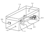
図1に本発明気密検査方法を実施する気密検査装置の検査液槽の概略構成を斜視図で示す。気密検査装置は、まず、検査液槽10に検査液13を蓄えた状態で被検査物40を液面下に浸漬させ、被検査物40内に加圧した場合においてもなるべく形状変化を起こさないように固定する。検査液槽10には、あらかじめ、検査液槽10中の任意の液面下に液槽内に向けて配置された超音波送信部20と、同様に、検査液槽10中の任意の液面下の超音波送信部20と異なる位置に液槽内に向けて配置された超音波受信部30とが備えられており、超音波送信部20と超音波受信部30は電圧変化を超音波に、あるいはその逆に変換する電歪素子で構成されている。また、被検査物40は、図示していないが、搬送を行うためのハンドリング装置と、昇降を行う昇降装置等によって、供給、浸漬、排出が行われる。
FIG. 1 is a perspective view showing a schematic configuration of a test liquid tank of an airtight inspection apparatus for carrying out the airtight inspection method of the present invention. First, the airtightness inspection apparatus does not cause a change in shape as much as possible even when the
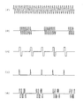
被検査物40が浸漬している間、超音波送信部20からは、既定のパターン波形を繰り返し送信するような周期性超音波が常時放射されている。超音波受信部30は、配置された位置において受信面に受けうる音圧によって変換される電圧波形を受信する。超音波送信部20から放射される、既定のパターン波形を繰り返し送信するような周期性超音波には、図3の(イ)に例示したような、正弦波連続波や、(ロ)に例示したようなバースト正弦波、(ハ)に例示したようなデューティ比の異なる矩形波、(ニ)に例示したような周期性パルス波、あるいは(ホ)に例示したようなコード化符号信号などが用いられる。
While the
(イ)の正弦波連続波は連続性を有しているので、漏洩の検出や漏洩位置の推定においてが定在音場を作りやすく、変化の即応性や周期性に優れているが耐ノイズ性や検出の容易さに難がある。(ハ)や(ニ)は、間欠性波形であるため漏洩の検出や漏洩位置の推定においてが定在音場の形成や受信波形の周期性の検出に時間がかかるが耐ノイズ性や検出の容易さに優れている。(ロ)は上記(イ)と(ハ)の間に位置する特徴を有している。(ホ)は、波形の連続性と波形振幅などの経時変化とを併せ持っているため定在音場が作りやすく、変化の即応性や周期性に優れており、波形の経時変化を有しているため耐ノイズ性や誤検出訂正の容易さなど優れている点が多い。 Since the sine wave continuous wave of (a) has continuity, it is easy to create a standing sound field in the detection of leak and estimation of the leak position, and it has excellent responsiveness and periodicity of change, but it is noise resistant. There is a difficulty in sex and ease of detection. Since (c) and (d) are intermittent waveforms, it takes time to form a standing sound field and detect the periodicity of the received waveform in the detection of leakage and estimation of the leakage position. Excellent ease. (B) has a feature located between (a) and (c) above. (E) has both continuity of waveform and changes over time such as waveform amplitude, so it is easy to create a standing sound field, and it has excellent responsiveness and periodicity of change, and has changes over time of waveform. Therefore, there are many advantages such as noise resistance and ease of false detection and correction.
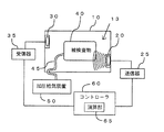
図2は検査液槽を上面から見た気密検査装置の概略構成図を示す。被検査物40には、内部に気体を加圧供給するための給気管45が接続されており、給気管45は検査液槽10外の加圧給気装置50に繋がっている。超音波送信部20は検査液槽10外に設けられた送信器25に、一方、超音波受信部30は受信器35に夫々接続され、さらにこれらは演算部65を備えたコントローラ60に繋がっている。
FIG. 2 is a schematic configuration diagram of an airtight inspection apparatus when the inspection liquid tank is viewed from above. An air supply pipe 45 for pressurizing and supplying gas is connected to the object to be inspected 40, and the air supply pipe 45 is connected to a pressurized
ここで給気管45は、被検査物40に対し着脱可能で被検査物40の検査液槽内への昇降に連動できるよう柔軟構造を有している。そして、送信器25はプログラム可能な周期性信号の源信発生部と超音波送信部20に使われている電歪素子を駆動するためのアンプを有している。受信器35は、超音波受信部30に使われている電歪素子からの微弱な電圧信号を精度良く増幅するための低ノイズ増幅回路と必要に応じて受信を切り替えるスイッチ回路を有している。
Here, the air supply pipe 45 is detachable with respect to the
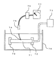
図4に超音波送信部20から放射された超音波が検査液槽内で複雑に反射して受信される状況を概念図で示す。超音波受信部30は、超音波送信部20から液槽内に放射された超音波が槽壁や被検査物40と検査液13との境界面などの音響境界面で反射・拡散して減衰していく。音波の拡散エネルギーは方向ベクトルを有しているため、検査液槽10内の任意の位置の任意の方向に対して任意の経時的音圧変化を示す、つまり、超音波受信部30の配置位置が異なると経時的音圧変化が異なり、同じ位置であっても受信面の方向が異なると経時的音圧変化が異なることとなる。また、超音波送信部20と超音波受信部30の配置位置は必ずしも検査液槽10内で無くても良く、検査液槽10に接した検査液槽外でも良いが、検査液槽10を構成する材料内を伝播する超音波の影響が大きい場合には、検査の難易度が高くなり、検査液槽10や液面14に接しない検査液槽外では、空気など音響抵抗が著しく異なる物質が介在するために検査は困難となる。
FIG. 4 is a conceptual diagram showing a situation in which ultrasonic waves radiated from the
図5及び図6は超音波送信部20から放射された超音波が検査液槽内で複雑に乱反射して、結果的に定在音場を生じることを概念図で示す。即ち、図5は検査液槽を上面から見た概念図であり、図6は検査液槽を側面から見た概念図である。
5 and 6 are conceptual diagrams showing that the ultrasonic wave radiated from the
これら図に示すように、超音波送信部20から放射された既定のパターン波形を繰り返し送信するような周期性超音波は検査液槽内の音響境界面で複雑に反射・拡散し、その結果として検査液槽10内に超音波の重畳による経時的音圧の周期的変化である定在音場を示す。定在音場は、超音波送信部20から、前記周期性超音波が常時送信され、検査液槽10内で放射された超音波が反射・拡散する音響境界面や検査液13に音響に係わるような経時的変化が無い場合に既定の定在音場を生じる。検査液13に生じる流動や温度分布、浮遊物によっても定在音場に変化が生じるが、温度分布による変化は流動による変化より小さく、流動による変化は微少であり定在音場に大きな影響を及ぼす程ではない。浮遊物による変化は様々考えられるが、そのほとんどが親水性であるため変化は無視できる程度である。検査液槽10内に生じた定在音場は、被検査物40を取り囲む検査液13の全ての箇所で観測される。しかし、検査液槽10や被検査物40の形状によっては、少なくない領域に定在音場の著しく希薄な部分が生じることがあるので、望ましくは、定在音場の著しく希薄な部分が生じないように超音波送信部20の配置を考慮するか、複数の超音波送信部を配置することも考慮される。
As shown in these figures, periodic ultrasonic waves that repeatedly transmit a predetermined pattern waveform radiated from the
図7に被検査物40に欠陥部41がある場合の検査気体加圧前後での欠陥部41付近の拡大概念図を示す。検査液13に浸漬された被検査物40の欠陥部41は極めて小さな空隙であるため、浸漬しただけでは検査液13の表面張力と被検査物40にあらかじめ入っている気体の気圧が平衡し、検査液13への気体漏れも被検査物40内への検査液13の浸透も生じない。このため、被検査物の欠陥部41付近で反射する超音波は被検査物40の形状に依存した単純なものとなる。被検査物40に接続されている給気管45から被検査物40の内部に検査気体16を圧送供給すると前記平衡が崩れ、欠陥部41から検査気体16が被検査物40の表面に沿うように漏洩し、検査液13側に気泡17が生じる。欠陥部41は極めて微少であるので、加圧によって生じた気泡17は被検査物40表面に付着したままで検査液13中に離脱することは少ない。あるいは、被検査物40が薄い金属板や樹脂など脆弱な材料構造である場合においては、加圧供給する検査気体16の圧力を余り大きく取ると被検査物40の材質変形を引き起こし、欠陥部以外においても加圧により剥離や割れを生じる恐れがあるため、加圧力を余り大きくできず、1.1から1.2倍程度の加圧しかできない。このような場合においても、同様に加圧によって生じた気泡17は被検査物40表面に付着したままで検査液13中に離脱することは少ない。
FIG. 7 shows an enlarged conceptual diagram of the vicinity of the defect portion 41 before and after pressurizing the inspection gas when the
図8に被検査物40に欠陥部41がある場合の検査気体加圧前後での欠陥部41付近に設置した超音波受信部30での概略受信波形を示し、(イ)は加圧前、(ロ)は加圧後である。超音波送信部20から被検査物40の欠陥部41に向けて検査液13中に放射された2MHz連続波超音波は、拡散・減衰しながら検査液13中を進行し、被検査物40と検査液13との境界面において反射する。被検査物40に検査気体を加圧供給する前では、(イ)に示すように超音波は被検査物40と検査液13との境界面において比較的単純な反射を起こすため、欠陥部41付近に配された超音波受信部30においても2MHz付近の周波数成分を多く含む単純な正弦波状連続波が受信される。
FIG. 8 shows a schematic received waveform at the
一方、被検査物40に検査気体16を加圧供給すると、(ロ)に示すように欠陥部41から検査気体16が被検査物40の表面に沿うように漏洩し、検査液13側に気泡17が生じるので、超音波送信部20から放射された2MHz連続波超音波は、欠陥部41に生じた気泡17と検査液13との境界面および被検査物40と検査液13との境界面で反射し、加圧前とは異なった反射方向や反射率を生じるために超音波受信部30において受信される電圧波形は周期性が失われ、加圧前とは異なった波形となる。また、ほとんどの場合、加圧供給により欠陥部41からは検査気体16の微少な漏洩が継続するので、欠陥部41に生じた気泡17と検査液13との境界面での超音波の反射状況は経時的な変化を示し、超音波受信部30で受信される電圧波形の周期性も失われる。
On the other hand, when the inspection gas 16 is supplied to the
超音波受信部30で受信された電圧波形を受信器35を経由してコントローラ60や演算部65でフィルタやFFT、ウェーブレット等の演算解析手法によって記憶演算することにより、加圧前後の波形の周波数パワースペクトルに係わる特徴量と周期性を求めて比較することにより受信波形の加圧前後での変化を検出することができる。かくして、検査槽10内の音響環境の変化つまり被検査物40の欠陥部41からの検査気体16の極めて微少な漏洩の有無を検出することができる。
The frequency of the waveform before and after pressurization is obtained by storing and calculating the voltage waveform received by the ultrasonic
図9は本発明の第2の実施態様として超音波受信部を異なる2カ所に配置した場合の概略図を示す。この場合においては、検査液槽10に満たされた検査液13内の任意の位置に超音波送信部20とこれと異なる検査液13内の任意の位置に第1の超音波受信部30Aとこれらと異なる検査液13内の任意の位置に第2の超音波受信部30Bとを配し、被検査物40が浸漬されている。超音波送信部20からは、検査液槽10内の検査液13に、既定のパターン波形を繰り返し送信するような周期性超音波が常時放射されている。放射された超音波は、槽壁や被検査物40と検査液13との境界面などの音響境界面で反射・拡散して減衰していき、検査液槽10内に定在音場を形成する。このとき、前記第1の超音波受信部30Aの受信面から検査液槽10内を見た場合の音響環境と前記第2の超音波受信部30Bの受信面から検査液槽10内を見た場合の音響環境とは異なるため、前記第1の超音波受信部30Aの受信面と前記第2の超音波受信部30Bの受信面とで受信された電圧波形は異なる。
FIG. 9 shows a schematic view when the ultrasonic wave receiving units are arranged at two different places as the second embodiment of the present invention. In this case, the
図10(イ),(ロ)に被検査物40に欠陥部41がある場合の検査気体加圧前後での前記第1の超音波受信部30Aでの受信波形の比較と、図11(イ),(ロ)に被検査物40に欠陥部41がある場合の検査気体加圧前後での前記第2の超音波受信部30Bでの受信波形の比較とを示す。加圧前の第1の超音波受信部30Aで受信される受信波形と第2の超音波受信部30Bで受信される受信波形とは、それぞれの受信部の受面から見た音響環境を反映したものであるので、それぞれで受信された電圧波形を受信器35を経由して図2におけるコントローラ60内の演算部65でフィルタやFFT、ウェーブレット等の演算解析手法によって記憶演算することにより、加圧前の第1の超音波受信部30Aでの音響環境と第2の超音波受信部30Bでの音響環境の特徴を波形の周波数パワースペクトルに係わる特徴量として求めることができる。受信波形の違いは超音波送信部20から第1の超音波受信部30Aあるいは第2の超音波受信部30Bに至る超音波の伝播状況の違いにより生じるため、演算部65で求められた特徴量は、超音波送信部20から第1の超音波受信部30Aあるいは第2の超音波受信部30Bに至る超音波の伝播状況を示す指標となる。また、同様に演算部65で求められた周期性の特徴量は前記の如く検査液槽10内の音響環境が安定し、定在音場を形成していることを表している。
10 (a) and 10 (b), a comparison of received waveforms at the first ultrasonic receiver 30A before and after the test gas pressurization when the
被検査物40に検査気体16を加圧供給すると、欠陥部41から検査気体16が被検査物40の表面に沿うように漏洩し、検査液13側に気泡17が生じるので、超音波送信部20から放射された超音波は、欠陥部41に生じた気泡17と検査液13との境界面および被検査物40と検査液13との境界面で反射し、加圧前とは異なった反射方向や反射率を生じるために前記第1の超音波受信部30Aにおいて受信される電圧波形と前記第2の超音波受信部30Bにおいて受信される電圧波形とは周期性が失われ、加圧前とは異なった波形となる。また、その波形変化は第1の超音波受信部30Aにおいて受信される電圧波形と第2の超音波受信部30Bにおいて受信される電圧波形とでは異なった変化を示す。この変化の違いは超音波送信部20から第1の超音波受信部30Aあるいは第2の超音波受信部30Bに至る超音波の伝播過程において、気泡17が生じる相対位置関係が異なることに由来する。このことから、加圧後の第1の超音波受信部30Aで受信される電圧波形と第2の超音波受信部30Bで受信される電圧波形とを受信器35を経由してコントローラ60内の演算部65でフィルタやFFT、ウェーブレット等の演算解析手法によって記憶演算することにより、周波数スペクトルの変化傾向、及び周波数スペクトルに係わる特徴量の変化、変化応答時間、周期性の喪失傾向の違いなどから音響環境の変化位置を推定することができる。
When the inspection gas 16 is pressurized and supplied to the
さらに、検査液槽10内に配置する超音波受信部30の数を2ケ所に限らず、それ以上に増やしそれぞれ異なる位置や向きに配置することにより、欠陥部41の位置をより正確に推定することができる。しかし、超音波受信部を増やすと解析により多くの時間を要することになるため、検査時間と位置推定精度とのバランスが問題となる。また、超音波送信部20を複数個とし、超音波受信部30を1個としても理論的には同様の推定が可能であるが、演算解析に用いる計測データつまり受信波形が1つしか得られないため、受信器35や演算部65に高精度が要求され、難易度が高くなってしまうため、好ましくない。さらにまた、超音波送信部20と超音波受信部30をともに複数個とすることも可能であり、容易に考えられる。
Furthermore, the number of the
被検査物が量産品などの同一形状物である場合には、予め被検査物の様々な位置に作為的に欠陥部を作成した模擬物を用意し、この模擬物を使って欠陥部からの検査気体の漏洩により、超音波受信部で受信された電圧波形の変化をコントローラ内の演算部で演算解析し、前記漏洩の有無の検出や前記位置推定に必要な特徴量を予め求めておき、これをコントローラ内に記憶して、前記漏洩の有無の検出や前記位置推定の参照値とすることによって、演算解析を高速且つ容易にすることもできる。 If the object to be inspected has the same shape, such as a mass-produced product, prepare a simulated object in which a defective part is intentionally created at various positions of the inspected object in advance, and use this simulated object to remove from the defective part. Due to the leakage of the inspection gas, the change in the voltage waveform received by the ultrasonic wave receiving unit is calculated and analyzed by the calculation unit in the controller, and the characteristic amount necessary for the detection of the presence or absence of the leak and the position estimation is obtained in advance. By storing this in the controller and using it as a reference value for the presence / absence of leakage or the position estimation, the calculation analysis can be made fast and easy.
10:検査液槽
13:検査液
14:液面
16:検査気体
17:超音波送信部
25:送信器
30:超音波受信部
30A:第1の超音波受信部
30B:第2の超音波受信部
35:受信器
40:被検査物
41:欠陥部
45:給気管
50:加圧給気装置
60:コントローラ
65:演算部
70:フィルター
71:鋼管
72:保持装置
73:空気圧送装置
74:貫通孔
75:検出装置
76:水槽
77:記録計
10: Test liquid tank 13: Test liquid 14: Liquid surface 16: Test gas 17: Ultrasonic transmitter 25: Transmitter 30: Ultrasonic receiver 30A: First ultrasonic receiver 30B: Second ultrasonic receiver Part 35: Receiver 40: Inspected object 41: Defect part 45: Air supply pipe 50: Pressurized air supply apparatus 60: Controller 65: Calculation part 70: Filter 71: Steel pipe 72: Holding apparatus 73: Pneumatic feeder 74: Penetration Hole 75: Detection device 76: Water tank 77: Recorder
Claims (4)
前記検査液槽内の異なる任意の位置に超音波送信部と、超音波受信部とを配置し、
前記検査液槽内に超音波送信部から既定のパターン波形を繰り返し送信するような周期性超音波によって定在音場を作り出し、超音波受信部において被検査物の欠陥部から発生した気泡による前記定在音場の変化を定在波形の周波数パワースペクトルの変化として検知し、加圧前と加圧後の前記周波数パワースペクトルを比較することにより被検査物の気密性を検査することを特徴とする気密検査方法。 Bubbles generated from a defective part of the pressurized test object by immersing the test object in the test liquid in the test liquid tank, supplying gas into the test object from a pipe connected to the test object In the airtight inspection method for inspecting the airtightness of the object to be inspected by detecting
An ultrasonic transmission unit and an ultrasonic reception unit are arranged at different arbitrary positions in the inspection liquid tank,
Wherein creating a test liquid tank to the ultrasonic transmission periodicity as repeatedly transmits the predetermined pattern waveform from unit ultrasound by standing sound field, due to the air bubbles generated from the defect portion of the specimen Te ultrasonic receiver smell A change in the standing sound field is detected as a change in the frequency power spectrum of the standing waveform, and the airtightness of the inspection object is inspected by comparing the frequency power spectrum before and after pressurization. Airtight inspection method.
前記検査液槽内の検査液に対して超音波を送信し、前記検査液槽内に隙間無く定在波を作り出すために、前記検査液槽内の任意の位置に超音波送信部を配置すると共に、
前記検査液槽内の異なる任意の位置に超音波受信部を配置し、
前記検査液槽内に前記超音波送信部から既定のパターン波形を繰り返し送信するような周期性超音波によって定在音場を作り出す一方、前記超音波受信部において被検査物の欠陥部から発生した気泡による前記定在音場の変化を定在波形の周波数パワースペクトルの変化として検知し、加圧前と加圧後の前記周波数パワースペクトルを比較することにより被検査物の気密性を検査するようになしたことを特徴とする気密検査装置。 Bubbles generated from a defective part of the pressurized test object by immersing the test object in the test liquid in the test liquid tank, supplying gas into the test object from the pipe connected to the test object An airtight inspection device that inspects the airtightness of an object to be inspected by detecting
In order to transmit an ultrasonic wave to the test liquid in the test liquid tank and create a standing wave in the test liquid tank without a gap, an ultrasonic transmitter is disposed at an arbitrary position in the test liquid tank. With
An ultrasonic receiving unit is arranged at any arbitrary position in the inspection liquid tank,
While creating a standing sound field by periodic ultrasonic so as to repeatedly transmit the predetermined pattern waveform from the ultrasonic transmission part to the test liquid tank, generated from the defect portion of the specimen Te said ultrasonic receiver smell The change in the standing sound field due to the air bubbles is detected as a change in the frequency power spectrum of the standing waveform, and the airtightness of the inspection object is inspected by comparing the frequency power spectrum before and after the pressurization. An air tightness inspection device characterized by that.
Priority Applications (1)
| Application Number | Priority Date | Filing Date | Title |
|---|---|---|---|
| JP2005256326A JP4232183B2 (en) | 2005-09-05 | 2005-09-05 | Airtight inspection method and apparatus |
Applications Claiming Priority (1)
| Application Number | Priority Date | Filing Date | Title |
|---|---|---|---|
| JP2005256326A JP4232183B2 (en) | 2005-09-05 | 2005-09-05 | Airtight inspection method and apparatus |
Publications (2)
| Publication Number | Publication Date |
|---|---|
| JP2007071574A JP2007071574A (en) | 2007-03-22 |
| JP4232183B2 true JP4232183B2 (en) | 2009-03-04 |
Family
ID=37933154
Family Applications (1)
| Application Number | Title | Priority Date | Filing Date |
|---|---|---|---|
| JP2005256326A Expired - Fee Related JP4232183B2 (en) | 2005-09-05 | 2005-09-05 | Airtight inspection method and apparatus |
Country Status (1)
| Country | Link |
|---|---|
| JP (1) | JP4232183B2 (en) |
Families Citing this family (14)
| Publication number | Priority date | Publication date | Assignee | Title |
|---|---|---|---|---|
| JP5283569B2 (en) * | 2009-06-02 | 2013-09-04 | 富士通株式会社 | Earpiece structure, cellular phone, and waterproof performance test method and apparatus for telephone apparatus |
| JP5739315B2 (en) * | 2011-11-25 | 2015-06-24 | 日立Geニュークリア・エナジー株式会社 | Ultrasonic leak detection device and method |
| RU2488792C1 (en) * | 2011-12-20 | 2013-07-27 | Федеральное государственное унитарное предприятие "Центральный аэрогидродинамический институт имени профессора Н.Е. Жуковского" (ФГУП "ЦАГИ") | Product leakage measuring device |
| RU2488084C1 (en) * | 2011-12-20 | 2013-07-20 | Федеральное государственное унитарное предприятие "Центральный аэрогидродинамический институт имени профессора Н.Е. Жуковского" (ФГУП "ЦАГИ") | Method to measure leakage of items |
| RU2562155C1 (en) * | 2014-06-05 | 2015-09-10 | Федеральное государственное унитарное предприятие "Центральный аэрогидродинамический институт имени профессора Н.Е. Жуковского" (ФГУП "ЦАГИ") | Device for determining air-tightness at strength tests |
| CN108398216A (en) * | 2018-01-25 | 2018-08-14 | 浙江众泰汽车制造有限公司 | A kind of blocking piece leakage electroacoustic test device and test method |
| CN109060254B (en) * | 2018-09-06 | 2023-10-27 | 潍坊思博精工科技有限公司 | Diesel engine cylinder head waterway seal detection device |
| JP2020143937A (en) * | 2019-03-04 | 2020-09-10 | 中道鉄工株式会社 | Ultrasonic leakage inspection device |
| JP2020143938A (en) * | 2019-03-04 | 2020-09-10 | 中道鉄工株式会社 | Ultrasonic leakage inspection device |
| JP7230301B2 (en) * | 2019-03-04 | 2023-03-01 | 中道鉄工株式会社 | Ultrasonic leak tester |
| JP7372792B2 (en) | 2019-09-12 | 2023-11-01 | 古野電気株式会社 | Underwater detection device and bubble detection method |
| CN111551321B (en) * | 2020-06-14 | 2021-12-03 | 南昌市燃气集团有限公司 | Measuring method of airtight container leakage positioning measuring system based on ultrasonic detection |
| CN112763206B (en) * | 2020-12-30 | 2022-04-22 | 中国计量大学 | Refrigerant valve leakage test system |
| CN117571222B (en) * | 2024-01-16 | 2024-04-09 | 山东科沃泽机械科技有限公司 | Air tightness testing device for rear axle transmission shell of tractor |
-
2005
- 2005-09-05 JP JP2005256326A patent/JP4232183B2/en not_active Expired - Fee Related
Also Published As
| Publication number | Publication date |
|---|---|
| JP2007071574A (en) | 2007-03-22 |
Similar Documents
| Publication | Publication Date | Title |
|---|---|---|
| JP4232183B2 (en) | Airtight inspection method and apparatus | |
| JP4630399B2 (en) | Ultrasonic leak position detector | |
| US8240209B2 (en) | Method and apparatus for detecting damage to high-pressure tank | |
| CN106441507B (en) | The system and method for non-intruding and continuous level gauging are carried out in hydrostatic column | |
| JP6095518B2 (en) | AE test equipment and method for composite tank | |
| JPH07318336A (en) | Method and equipment to check pipeline with ultrasonic wave | |
| KR100955035B1 (en) | Method for test detection of secondary barrier | |
| JP2019504311A (en) | Crack measuring apparatus and method | |
| JP6502821B2 (en) | Valve seat leak inspection apparatus and valve seat leak inspection method | |
| Cawley | Guided waves in long range nondestructive testing and structural health monitoring: Principles, history of applications and prospects | |
| JPWO2009093738A1 (en) | Method for inspecting fluid containers for leak holes | |
| Tscheliesnig et al. | Detecting corrosion during inspection and maintenance of industrial structures using acoustic emmision | |
| JP2020143940A (en) | Ultrasonic leakage inspection device | |
| Moon et al. | Ultrasound techniques for leak detection | |
| US9829469B2 (en) | Apparatus and method for measuring nonlinear parameters | |
| Riahi et al. | Health monitoring of aboveground storage tanks’ floors: A new methodology based on practical experience | |
| JP7230301B2 (en) | Ultrasonic leak tester | |
| KR101589200B1 (en) | Sensor fixing apparatus for non-destructive test in lamb wave and non-destructive test system having the same | |
| Ranzolin Piazzetta et al. | Leak detection in pressure vessels using ultrasonic techniques | |
| JP2020143938A (en) | Ultrasonic leakage inspection device | |
| JP3171284U (en) | Underground tank thickness measuring device | |
| CN218974262U (en) | Ultrasonic probe for pipeline detection | |
| JP4978870B2 (en) | Leakage pipe inspection method and inspection apparatus | |
| JP3046188B2 (en) | Method and apparatus for testing airtight leakage of containers | |
| Hu | Damage Detection of Submerged Structures Using Linear and Nonlinear Guided Waves |
Legal Events
| Date | Code | Title | Description |
|---|---|---|---|
| A977 | Report on retrieval |
Free format text: JAPANESE INTERMEDIATE CODE: A971007 Effective date: 20080401 |
|
| A131 | Notification of reasons for refusal |
Free format text: JAPANESE INTERMEDIATE CODE: A131 Effective date: 20080909 |
|
| A521 | Written amendment |
Free format text: JAPANESE INTERMEDIATE CODE: A523 Effective date: 20080924 |
|
| TRDD | Decision of grant or rejection written | ||
| A01 | Written decision to grant a patent or to grant a registration (utility model) |
Free format text: JAPANESE INTERMEDIATE CODE: A01 Effective date: 20081111 |
|
| A01 | Written decision to grant a patent or to grant a registration (utility model) |
Free format text: JAPANESE INTERMEDIATE CODE: A01 |
|
| A61 | First payment of annual fees (during grant procedure) |
Free format text: JAPANESE INTERMEDIATE CODE: A61 Effective date: 20081128 |
|
| FPAY | Renewal fee payment (event date is renewal date of database) |
Free format text: PAYMENT UNTIL: 20111219 Year of fee payment: 3 |
|
| R150 | Certificate of patent or registration of utility model |
Free format text: JAPANESE INTERMEDIATE CODE: R150 |
|
| FPAY | Renewal fee payment (event date is renewal date of database) |
Free format text: PAYMENT UNTIL: 20151219 Year of fee payment: 7 |
|
| R250 | Receipt of annual fees |
Free format text: JAPANESE INTERMEDIATE CODE: R250 |
|
| LAPS | Cancellation because of no payment of annual fees |