JP4228320B2 - Image processing apparatus and method, and program - Google Patents
Image processing apparatus and method, and program Download PDFInfo
- Publication number
- JP4228320B2 JP4228320B2 JP2006246175A JP2006246175A JP4228320B2 JP 4228320 B2 JP4228320 B2 JP 4228320B2 JP 2006246175 A JP2006246175 A JP 2006246175A JP 2006246175 A JP2006246175 A JP 2006246175A JP 4228320 B2 JP4228320 B2 JP 4228320B2
- Authority
- JP
- Japan
- Prior art keywords
- image
- face
- images
- determined
- template
- Prior art date
- Legal status (The legal status is an assumption and is not a legal conclusion. Google has not performed a legal analysis and makes no representation as to the accuracy of the status listed.)
- Expired - Fee Related
Links
Images


Classifications
-
- G—PHYSICS
- G06—COMPUTING; CALCULATING OR COUNTING
- G06T—IMAGE DATA PROCESSING OR GENERATION, IN GENERAL
- G06T11/00—2D [Two Dimensional] image generation
- G06T11/60—Editing figures and text; Combining figures or text
Description
本発明は画像処理装置および方法、並びにプログラムに関し、特に、人の顔などが適切に切り出された画像を、適切に配置したアルバムを作成できるようにした画像処理装置および方法、並びにプログラムに関する。 The present invention relates to an image processing apparatus, method, and program, and more particularly, to an image processing apparatus, method, and program capable of creating an album in which images obtained by appropriately cutting out human faces and the like are appropriately arranged.
デジタルカメラなどが普及し、デジタルカメラで撮影された画像を、パーソナコンピュータなどで気軽に閲覧することができる。 Digital cameras and the like have become widespread, and images taken with digital cameras can be easily browsed with a personal computer or the like.
デジタルカメラが普及する前には、いわゆるフィルムカメラなどと称されるカメラが一般的に用いられていた。フィルムカメラにより撮影された画像(写真)は、所定の紙に印刷された状態で閲覧することが一般的であった。それらの写真は、台紙に貼付された状態でアルバムなどと称される形式で管理されることがあった。 Before the popularization of digital cameras, cameras called so-called film cameras were generally used. In general, an image (photograph) taken by a film camera is browsed in a state of being printed on predetermined paper. Those photographs are sometimes managed in a form called an album or the like in a state of being affixed to the mount.
このようなフィルムカメラにおいて撮影された画像を閲覧するときに用いられていたアルバムを、デジタルカメラにおいて撮影された画像を閲覧するときにも利用することが提案されつつある。デジタルカメラにおいて撮影された画像を閲覧するアルバムは、電子アルバムなどと称されることがある。 It has been proposed to use an album that has been used when browsing images taken with such a film camera also when browsing images shot with a digital camera. An album that browses images taken by a digital camera may be referred to as an electronic album.
電子アルバムは、パーソナルコンピュータのディスプレイや、テレビジョン受像機などで閲覧することができる。また、電子アルバムは、紙媒体のアルバムと同じ感覚で扱えるように、複数のページで構成され、ページをめくると次のページが表示されるといった表示形態を備えているのが一般的である。ユーザは、紙媒体のアルバムと同じ感覚で電子アルバムを楽しむことができる。 The electronic album can be viewed on a display of a personal computer, a television receiver or the like. Also, an electronic album is generally composed of a plurality of pages so that it can be handled in the same manner as an album on paper media, and generally has a display form in which the next page is displayed when the page is turned. The user can enjoy the electronic album with the same feeling as the paper medium album.
紙媒体のアルバムは、ユーザが、自分で写真を台紙に貼ることにより作成される。電子アルバムの場合、ディスプレイ上に表示されているページをイメージした画面に、ユーザが所定の操作を行うことで画像を貼り付けることにより、アルバムを作成することもできるが、ユーザの手を煩わすことなく画像をページ内に配置し、アルバムを作成することも提案されている。アルバムを作成するときなど、適切な画像をページに貼り付けるために、何らかの加工が行われることも提案されている。
電子アルバムを、ユーザの手を煩わすことなく作成するような場合、適切な画像をページに貼り付けるために、何らかの加工が行われることがあるが、撮影者の意図を反映した形で加工が行われることが好ましい。 When creating an electronic album without bothering the user, some processing may be performed to paste an appropriate image on the page, but the processing is performed in a way that reflects the photographer's intention. Are preferred.
本発明は、このような状況に鑑みてなされたものであり、画像を加工するとき、その画像を撮影した撮影者の意図を反映した形で加工が行われるようにするものである。 The present invention has been made in view of such a situation. When an image is processed, the processing is performed in a manner reflecting the intention of a photographer who has captured the image.
本発明の一側面の画像処理装置は、第1の画像から顔と判断される領域を検出する検出処理手段と、前記検出処理手段により検出された前記顔と判断された領域が所定のサイズ以上であるか否かを判定する判定処理手段と、前記顔と判断された領域が所定のサイズ以上であると判定された場合、前記第1の画像から前記顔と判断された領域を含む第2の画像を、所定のアスペクト比で切り出す切り出し処理手段とを備え、前記判定処理手段は、前記顔と判断された領域が所定のサイズ以上でないと判定された場合、所定の数以上の顔が検出されたか否かを判定し、前記切り出し処理手段は、所定の数以上の顔が検出されたと判定された場合、顔を最も多く含む領域の第2の画像を、前記画像から所定のアスペクト比で切り出し、さらに、前記判定処理手段は、所定の数以上の顔が検出されていないと判定された場合、検出された顔が特定の顔の条件を満たしている顔であるか否かを判定し、前記切り出し処理手段は、検出された顔が特定の顔の条件を満たしている顔であると判定された場合、特定の顔の条件を満たしている顔を含む第2の画像を、前記画像から所定のアスペクト比で切り出す。
前記第2の画像の配置を決定するテンプレートを管理する管理処理と、前記第2の画像を前記テンプレートと合成する合成処理手段とをさらに設けることができる。
An image processing apparatus according to an aspect of the present invention includes a detection processing unit that detects a region that is determined to be a face from a first image, and the region that is determined to be the face detected by the detection processing unit is greater than or equal to a predetermined size. Determination processing means for determining whether the area is determined to be or not, and a second area including the area determined to be the face from the first image when the area determined to be the face is determined to be greater than or equal to a predetermined size . And a cutout processing unit that cuts out the image with a predetermined aspect ratio, and the determination processing unit detects a predetermined number or more of faces when it is determined that the area determined to be the face is not a predetermined size or more. When it is determined that a predetermined number or more of faces have been detected, the clipping processing unit determines a second image of the region including the most faces from the image with a predetermined aspect ratio. Cut out and further When it is determined that a predetermined number of faces or more are not detected, the fixed processing means determines whether or not the detected face satisfies a specific face condition, and the clipping processing means If it is determined that the detected face satisfies the specific face condition, a second image including the face satisfying the specific face condition is extracted from the image with a predetermined aspect ratio. Cut out with .
A management process for managing a template for determining the arrangement of the second image and a synthesis processing means for synthesizing the second image with the template can be further provided.
本発明の一側面の画像処理方法は、第1の画像から顔と判断される領域を検出する検出処理ステップと、検出された前記顔と判断された領域が所定のサイズ以上であるか否かを判定する第1の判定処理ステップと、前記顔と判断された領域が所定のサイズ以上であると判定された場合、前記第1の画像から前記顔と判断された領域を含む第2の画像を、所定のアスペクト比で切り出す第1の切り出し処理ステップと、前記顔と判断された領域が所定のサイズ以上でないと判定された場合、所定の数以上の顔が検出されたか否かを判定する第2の判定処理ステップと、所定の数以上の顔が検出されたと判定された場合、顔を最も多く含む領域の第2の画像を、前記画像から所定のアスペクト比で切り出す第2の切り出し処理ステップと、所定の数以上の顔が検出されていないと判定された場合、検出された顔が特定の顔の条件を満たしている顔であるか否かを判定する第3の判定処理ステップと、前記切り出し処理手段は、検出された顔が特定の顔の条件を満たしている顔であると判定された場合、特定の顔の条件を満たしている顔を含む第2の画像を、前記画像から所定のアスペクト比で切り出す第3の切り出し処理ステップとを含む。
前記第2の画像の配置を決定するテンプレートに基づいて前記第2の画像を前記テンプレートと合成する合成処理ステップをさらに含むようにすることができる。
An image processing method according to an aspect of the present invention includes a detection processing step for detecting an area determined to be a face from a first image, and whether or not the detected area determined to be a face is a predetermined size or more. And a second image including an area determined to be the face from the first image when it is determined that the area determined to be the face is equal to or larger than a predetermined size. A first cut-out processing step for cutting out the image with a predetermined aspect ratio, and if it is determined that the area determined to be a face is not greater than or equal to a predetermined size, it is determined whether or not a predetermined number or more of faces have been detected A second determination processing step and a second cut-out process for cutting out, from the image, a second image of a region including the largest number of faces at a predetermined aspect ratio when it is determined that a predetermined number of faces or more are detected Steps and predetermined When it is determined that the above face is not detected, a third determination processing step for determining whether or not the detected face satisfies a specific face condition; and the cutout processing unit includes: When the detected face is determined to be a face that satisfies the specific face condition, a second image including the face that satisfies the specific face condition is extracted from the image with a predetermined aspect ratio. A third cut-out processing step to cut out .
The image processing apparatus may further include a synthesis processing step for synthesizing the second image with the template based on a template that determines the arrangement of the second image.
本発明の一側面のプログラムは、コンピュータに、第1の画像から顔と判断される領域を検出する検出処理ステップと、検出された前記顔と判断された領域が所定のサイズ以上であるか否かを判定する第1の判定処理ステップと、前記顔と判断された領域が所定のサイズ以上であると判定された場合、前記第1の画像から前記顔と判断された領域を含む第2の画像を、所定のアスペクト比で切り出す第1の切り出し処理ステップと、前記顔と判断された領域が所定のサイズ以上でないと判定された場合、所定の数以上の顔が検出されたか否かを判定する第2の判定処理ステップと、所定の数以上の顔が検出されたと判定された場合、顔を最も多く含む領域の第2の画像を、前記画像から所定のアスペクト比で切り出す第2の切り出し処理ステップと、所定の数以上の顔が検出されていないと判定された場合、検出された顔が特定の顔の条件を満たしている顔であるか否かを判定する第3の判定処理ステップと、前記切り出し処理手段は、検出された顔が特定の顔の条件を満たしている顔であると判定された場合、特定の顔の条件を満たしている顔を含む第2の画像を、前記画像から所定のアスペクト比で切り出す第3の切り出し処理ステップとを含む処理を実行させる。
本発明の一側面においては、第1の画像から顔と判断される領域が検出され、検出された顔と判断された領域が所定のサイズ以上であるか否かが判定され、顔と判断された領域が所定のサイズ以上であると判定された場合、第1の画像から顔と判断された領域を含む第2の画像が、所定のアスペクト比で切り出され、顔と判断された領域が所定のサイズ以上でないと判定された場合、所定の数以上の顔が検出されたか否かが判定され、所定の数以上の顔が検出されたと判定された場合、顔を最も多く含む領域の第2の画像が、画像から所定のアスペクト比で切り出され、所定の数以上の顔が検出されていないと判定された場合、検出された顔が特定の顔の条件を満たしている顔であるか否かが判定され、検出された顔が特定の顔の条件を満たしている顔であると判定された場合、特定の顔の条件を満たしている顔を含む第2の画像が、画像から所定のアスペクト比で切り出される。
According to one aspect of the present invention, there is provided a program for detecting , in a computer, a detection processing step for detecting an area determined as a face from a first image, and whether the detected area determined as a face is a predetermined size or more. A first determination processing step for determining whether or not a region determined to be the face includes a region determined to be the face from the first image when the region determined to be the face is determined to be greater than or equal to a predetermined size. A first cut-out processing step of cutting out an image with a predetermined aspect ratio; and if it is determined that the area determined to be a face is not greater than or equal to a predetermined size, determine whether or not a predetermined number or more of faces have been detected A second determination processing step, and when it is determined that a predetermined number or more of faces have been detected, a second image that is extracted from the image with a predetermined aspect ratio is extracted from the second image in the region that includes the most face Processing And a third determination processing step for determining whether or not the detected face satisfies a specific face condition when it is determined that a predetermined number of faces or more are not detected. When it is determined that the detected face is a face that satisfies a specific face condition, the cutout processing unit determines a second image including a face that satisfies the specific face condition as the image. And a third cut-out process step of cutting out at a predetermined aspect ratio.
In one aspect of the present invention, an area determined to be a face is detected from the first image, and it is determined whether or not the area determined to be a detected face is a predetermined size or more. If the determined area is determined to be equal to or larger than the predetermined size, the second image including the area determined to be the face from the first image is cut out with a predetermined aspect ratio, and the area determined to be the face is determined to be the predetermined area. If it is determined that the number of faces is not equal to or larger than the predetermined size, it is determined whether or not a predetermined number or more of faces are detected. If it is determined that a predetermined number or more of faces are detected, the second of the region containing the largest number of faces is determined. If the image is cut out from the image with a predetermined aspect ratio and it is determined that a predetermined number of faces or more are not detected, whether the detected face satisfies a specific face condition or not And the detected face meets the condition of a specific face If it is determined that the face has, the second image including the face that meets the conditions of the particular face, cut out from an image at a predetermined aspect ratio.
本発明の一側面によれば、画像を切り出すとき、切り出す領域として設定されている大きさのアスペクト比が維持された状態で、かつ、最大限に元の画像が含まれるように切り出しを行うことができるようになり、撮影者の意図を反映した形で画像の切り出しを行うことができる。 According to an aspect of the present invention, when an image is cut out, the image is cut out in such a manner that the aspect ratio of the size set as the cut-out area is maintained and the original image is included to the maximum extent. Thus, the image can be cut out in a manner reflecting the photographer's intention.
以下に、本発明の実施の形態について図面を参照して説明する。 Embodiments of the present invention will be described below with reference to the drawings.
[画像処理装置の構成について]
図1は、本発明の一実施の形態である画像処理装置の構成を示す図である。画像処理装置1は、HDD(Hard Disc Recorder)レコーダなどである。
[Configuration of image processing apparatus]
FIG. 1 is a diagram showing a configuration of an image processing apparatus according to an embodiment of the present invention. The image processing apparatus 1 is an HDD (Hard Disc Recorder) recorder or the like.
図1の画像処理装置1は、図示せぬ外部装置から供給されるAV(Audio Video)信号、または図示せぬアナログチューナ若しくは図示せぬラインチューナから供給されるアナログ信号として入力される映像信号および音声信号を記録または再生する。画像処理装置1は、再生された映像信号を、外部に接続されているモニタ2に出力する。また、画像処理装置1は、再生された音声信号を、外部に接続されているスピーカ3に出力する。
The image processing apparatus 1 in FIG. 1 includes an AV (Audio Video) signal supplied from an external device (not shown), a video signal input as an analog signal (not shown) or an analog signal supplied from a line tuner (not shown), and Record or play audio signals. The image processing apparatus 1 outputs the reproduced video signal to a
AV信号を供給する外部装置は、例えば、i.LINK(商標)を介して接続される外部装置、 デジタルBS(Broadcasting Satellite)チューナもしくはデジタルCS(Communications Satellite)チューナ、デジタルビデオカメラ、デジタルスチルカメラ、またはスキャナなどである。 External devices that supply AV signals include, for example, external devices connected via i.LINK (trademark), digital BS (Broadcasting Satellite) tuner or digital CS (Communications Satellite) tuner, digital video camera, digital still camera, Or a scanner.
画像処理装置1には、必要に応じてドライブ4が接続される。ドライブ4には、磁気ディスク(フレキシブルディスクを含む)、光ディスク(CD-ROM(Compact Disc-Read Only Memory)、DVD(Digital Versatile Disc)を含む)、光磁気ディスクを含む)、もしくは半導体メモリなどのリムーバブルメディア5が必要に応じて装着され、データの授受を行うようになされている。
A
図1の画像処理装置1は、コーデック11、サンプリングレートコンバータ12、アナログ入力処理部13、A/Dコンバータ14、切換部15、NTSC(National Television System Committee)デコーダ16、エンコーダ17、記録再生部18、操作部19、制御部20、デコーダ21、NTSCエンコーダ22、およびD/Aコンバータ23を含む構成とされている。
1 includes a
コーデック11は、図示せぬ外部装置から供給されるAV信号のうち、デジタルビデオ信号の圧縮を伸張し、NTSCデコーダ12に供給する。
The
サンプリングレートコンバータ12は、図示せぬ外部装置から供給されるAV信号のうち、デジタルオーディオ信号のサンプリングレートを異なるサンプリングレートに変換する。サンプリングレートコンバータ12は、変換されたデジタルオーディオ信号を切換部15に供給する。
The
アナログ入力処理部13は、制御部20から供給される、操作部19におけるユーザからの操作を示す信号に基づいて、図示せぬアナログチューナ、または図示せぬラインチューナから供給されるアナログ信号のうちの一方を選択する。アナログ入力処理部13は、選択されたアナログ信号のうちのアナログビデオ信号をNTSCデコーダ16に供給する。また、アナログ入力処理部13は、選択されたアナログ信号のうちのアナログオーディオ信号をA/Dコンバータ14に供給する。
The analog
A/Dコンバータ14は、アナログ入力処理部13から供給されたアナログオーディオ信号をA/D変換する。A/Dコンバータ14は、A/D変換された結果であるデジタルオーディオ信号を切換部15に供給する。
The A / D converter 14 A / D converts the analog audio signal supplied from the analog
切換部15は、制御部20から供給される、操作部19におけるユーザからの操作を示す信号に基づいて、サンプリングレートコンバータ12から供給されたデジタルオーディオ信号、またはA/Dコンバータ14から供給されたデジタルオーディオ信号のうちの一方を選択する。切換部15は、選択されたデジタルオーディオ信号をNTSCデコーダ16に供給する。
The switching
NTSCデコーダ16は、コーデック11より供給されたデジタルビデオ信号、またはアナログ入力処理部13より入力されたアナログビデオ信号を、NTSC方式のデジタルビデオ信号に変換する。NTSCデコーダ16は、変換されたNTSC方式のデジタルビデオ信号と、切換部15から供給されたデジタルオーディオ信号とを合成する。
The
画像処理装置1に入力される映像信号および音声信号を記録する場合は、NTSCデコーダ16は、合成された信号であるデジタルAV信号を、エンコーダ17に供給する。一方、画像処理装置1に入力される映像信号および音声信号を記録せずそのまま再生する場合は、NTSCデコーダ16は、合成された信号であるデジタルAV信号を、後述するNTSCエンコーダ22およびD/Aコンバータ23に供給する。
When recording a video signal and an audio signal input to the image processing apparatus 1, the
エンコーダ17は、NTSCデコーダ16より供給されたデジタルAV信号に対して、例えば、MPEG(Moving Picture Experts Group)方式などの所定の方式に従ったエンコード処理を施す。エンコーダ17は、エンコード処理の結果である圧縮符号化された信号データを記録再生部18に供給する。
The
記録再生部18は、例えば、ハードディスク(HDD)や光ディスクなどで構成される。記録再生部18は、エンコーダ17から供給された信号データを記録する。また、記録再生部18は、記録された信号データをデコーダ21に供給する。即ち、記録再生部18は、記録された信号データを再生する。
The recording / reproducing
操作部19は、例えば、各種の操作ボタン、キー、またはタッチパネルなどからなる。ユーザは、画像処理装置1に対する指示を入力するために操作部19を操作する。操作部19は、ユーザの操作に応じて、ユーザの操作を示す信号を制御部20に供給する。
The
制御部20は、例えば、マイクロプロセッサを含む構成とされ、操作部19から供給されるユーザの操作を示す信号に基づいて、画像処理装置1内の各部を制御する。
The
デコーダ21は、記録再生部18から供給された信号データに対して、例えば、MPEG方式などに対応する方式に従ったデコード処理を施す。デコーダ21は、処理の結果である伸張復号化されたデジタルAV信号のうちのデジタルビデオ信号をNTSCエンコーダ22に供給する。また、デコーダ21は、処理の結果である伸張復号化されたデジタルAV信号のうちのデジタルオーディオ信号をD/Aコンバータ23に供給する。
The
NTSCエンコーダ22は、デコーダ21から供給されたデジタルビデオ信号をNTSC方式のビデオ信号に変換する。NTSCエンコーダ22は、変換されたビデオ信号をモニタ2に供給する。
The
D/Aコンバータ23は、デコーダ21から供給されたデジタルオーディオ信号をD/A変換する。D/Aコンバータ23は、変換された結果であるオーディオ信号をスピーカ3に供給する。
The D / A converter 23 D / A converts the digital audio signal supplied from the
このような構成により、画像処理装置1は入力された映像信号および音声信号を記録、または再生することができる。また、画像処理装置1は、記録再生部18に記録されている映像信号や音声信号を再生することができる。
With such a configuration, the image processing apparatus 1 can record or reproduce the input video signal and audio signal. Further, the image processing apparatus 1 can reproduce the video signal and the audio signal recorded in the recording / reproducing
画像処理装置1は、映像信号の他、静止画像の信号(データ)も入力し、記録したり、再生したりする機能を有する。すなわち、本実施の形態における画像処理装置1は、動画像と静止画像を扱うことが可能な装置であり、例えば、エンコーダ17やデコーダ21は、動画像に適した方式や静止画像に適した方式を、サポートするように構成されている。
The image processing apparatus 1 has a function of inputting and recording or reproducing a still image signal (data) in addition to a video signal. That is, the image processing apparatus 1 according to the present embodiment is an apparatus capable of handling moving images and still images. For example, the
また、図1に示した構成例においては、映像信号を処理する構成を主に図示したが、同一の構成で、静止画像の画像データを処理できるように構成しても良いし、例えば、記録再生部18に直接的に静止画像データが記録されるような構成としても良く、図1に示した構成は適宜変更可能である。
In the configuration example shown in FIG. 1, the configuration for processing the video signal is mainly illustrated. However, the same configuration may be used so that the image data of the still image can be processed. A configuration in which still image data is directly recorded in the
図2は、図1の画像処理装置1の記録再生部18および制御部20の構成例を示す図である。
FIG. 2 is a diagram illustrating a configuration example of the recording / reproducing
記録再生部18は、静止画像データベース31、動画像データベース32、テンプレートデータベース33、およびコンテンツデータベース34を含む構成とされている。以下、静止画像データベース31を静止画像DB31と記述し、動画像データベース32を動画像DB32と記述し、テンプレートデータベース33をテンプレートDB33と記述し、コンテンツデータベース34をコンテンツDB34と記述する。
The recording /
静止画像DB31は、外部の装置から供給された静止画像のデータである静止画像データ、または、後述するように動画像から抽出された静止画像の静止画像データ(サムネイル画像のサムネイルデータ)を記録する。動画像DB32は、図1のエンコーダ17から供給された動画像のデータである動画像データを記憶する。なお、以下の説明において、例えば、“静止画像DB31に記録されている画像”との表記をするが、この“画像”は、“画像データ”の意味を含む表記であるとする。
The
テンプレートDB33は、コンテンツDB34に記録されるコンテンツであるアルバムを表示する場合の、アルバムに配置される画像の背景となる背景画像のデータである背景テンプレートおよびアルバムにおける画像の配置を設定する情報である配置テンプレートを記憶する。
The
コンテンツDB34は、アルバムのデータを記録する。なお、アルバムの詳細については後述するが、後述するように、アルバムとは、静止画像が貼り付けられたページから構成され、紙媒体のアルバムと同じ感覚で扱うことができ、電子アルバムなどと称されることもある。
The
制御部20は、選択部51、記録再生制御部52、表示制御部53、およびコンテンツ作成部54を含む構成とされている。
The
選択部51は、操作部19から供給される、ユーザの操作を示す信号に基づいて、ユーザにより操作される内容を示す情報を生成し、記録再生制御部52に供給する。
The
例えば、選択部51は、操作部19から供給される、モニタ2に表示されるアルバムなどを選択するユーザの操作を示す信号に基づいて、ユーザにより選択されたアルバムを示す情報を生成し、記録再生制御部52に供給する。
For example, the
また例えば、選択部51は、操作部19から供給される、画像が保存されている所定のフォルダを選択するユーザの操作を示す信号に基づいて、ユーザにより選択される所定のフォルダを示す情報を生成し、記録再生制御部52に供給する。
Further, for example, the
記録再生制御部52は、記録再生部18が行う記録、または再生を制御する。また記録再生制御部52は、記録再生部18から画像データ、背景テンプレート、配置テンプレート、またはアルバムのデータを読み出す。
The recording /
例えば記録再生制御部52は、選択部51から供給される、ユーザにより選択される所定のフォルダを示す情報に基づいて、静止画像DB31または動画像DB32から所定のフォルダに保存されている画像データを読み出す。
For example, the recording /
また記録再生制御部52は、読み出された画像データ、背景テンプレート、配置テンプレート、またはアルバムのデータを、コンテンツ作成部54に供給する。また、記録再生制御部52は、コンテンツ作成部54により作成されたコンテンツ(アルバムのデータ)を、コンテンツDB34に供給し、記憶させる。
Further, the recording /
表示制御部53は、記録再生制御部52により読み出された画像データ、背景テンプレート、配置テンプレート、またはアルバムのデータを基に、デコーダ21のデコ ード処理を制御する。
The
コンテンツ作成部54は、記録再生制御部52の制御の基、記録再生部18から供給される画像データを用いて、コンテンツを作成する。コンテンツ作成部54は、演算部71、およびテンプレート設定部72から構成される。
The
演算部71は、記録再生制御部52から供給される、画像に付随するデータに基づいて、複数の画像をグループに分ける(クラスタリングする)。演算部71は、クラスタリング部91、および階層決定部92から構成される。
The
クラスタリング部91は、記録再生制御部52から供給される、画像に付随するデータに基づいて、画像のクラスタリングを行う。 階層決定部92は、クラスタリング部91のクラスタリング結果であるクラスタの階層を決定する。
The
テンプレート設定部72は、記録再生瀬領部52に、背景テンプレートおよび配置テンプレートをテンプレートDB33から読み出させるための指示を出したり、読み出された背景テンプレートや配置テンプレートを生成されたクラスタに設定したりする。
The
またコンテンツ作成部54は、背景テンプレートおよび配置テンプレートが設定されたアルバムを、記録再生制御部52を介して記録再生部18のコンテンツDB34に記録させる。
The
このような構成を有する画像処理装置1の動作について説明する。以下の説明においては、アルバムを作成するときの画像処理装置1の動作を例に挙げて説明する。 The operation of the image processing apparatus 1 having such a configuration will be described. In the following description, the operation of the image processing apparatus 1 when creating an album will be described as an example.
[アルバム(コンテンツ)の作成について]
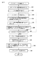
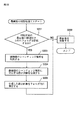
図3のフローチャートを参照し、アルバムの作成に係わる処理の概略について説明を加え、その後、各ステップの処理の詳細を、他の図面を参照して説明する。
[About creating an album (content)]
With reference to the flowchart of FIG. 3, an outline of processing related to album creation will be added, and then details of processing in each step will be described with reference to other drawings.
ステップS11において、画像データが読み出される。記録再生制御部52は、静止画像DB31から画像データを読み出す。このステップS11においては、画像データ本体ではなく、ステップS12で行われるクラスタリングの処理で必要とされる画像データに付随するデータが読み出される。画像データに付随するデータとして読み出されるのは、例えば、EXIF(Exchangeable Image File Format)タグである。
In step S11, image data is read. The recording /
画像データが読み出されるタイミング、すなわちこの場合、アルバムが作成されるタイミングとしては、以下のようなタイミングがある。 The timing at which image data is read, that is, in this case, the timing at which an album is created includes the following timing.
タイミング1として、ユーザの指示があったときである。ユーザは、アルバムを作成したいときに、アルバム作成の指示を、操作部19を操作して出す。ユーザが指示を出す場合であっても、例えば、ユーザがアルバムの作成を指示したタイミングで作成されるようにしても良いし、ユーザがアルバムの再生を指示したときに、アルバムが作成され、再生されるようにしても良い。
Timing 1 is when there is an instruction from the user. When the user wants to create an album, the user operates the
タイミング2として、静止画像を管理するフォルダが新たに作成されたときである。フォルダが作成されたときには、そのフォルダで管理される画像に対して、アルバムが作成される。
タイミング3として、既に作成されているフォルダに、新たな画像が追加されたときである。新たな画像が、既存のフォルダに追加された場合、その新たな画像を含めたアルバムが作成される。換言すれば、新たな画像を含めたアルバムに再編集される。
タイミング1乃至3は、タイミングの一例であり、限定を示すものではない。よって、タイミング1乃至3以外のタイミングで、アルバムの作成(ステップS11の処理)が開始されるようにしても良い。また、1つのタイミングに限定されるわけではなく、タイミング1乃至タイミング3および他のタイミングを、組み合わせて用いることも可能である。 Timings 1 to 3 are examples of timing and do not indicate limitations. Therefore, album creation (the process of step S11) may be started at a timing other than timings 1 to 3. Further, the timing is not limited to one, and timings 1 to 3 and other timings can be used in combination.
ステップS11において、画像データに付随し、クラスタリングの処理に必要とされる情報が読み出されると、ステップS12において、クラスタリングの処理が開始される。クラスタリングの処理についての詳細は後述する。クラスタリングの処理が実行されることにより、複数の画像が、複数のグループに分けられる。また1つのグループに注目したとき、その注目したグループ内の画像には、何らかの関連性があるように、クラスタリングが行われる。何らかの関連性とは、以下に説明するように、ここでは、時間的な関連性である。 In step S11, when information accompanying the image data and required for the clustering process is read, the clustering process is started in step S12. Details of the clustering process will be described later. By executing the clustering process, the plurality of images are divided into a plurality of groups. When attention is paid to one group, clustering is performed so that the images in the noticed group have some relationship. Some relevance is temporal relevance here, as will be described below.
ステップS12において、クラスタリングが行われると、その処理結果に基づき、ステップS13において背景テンプレートが読み出される。また、ステップS14において、配置テンプレートが読み出される。 When clustering is performed in step S12, a background template is read out in step S13 based on the processing result. In step S14, the arrangement template is read out.
ここで、背景テンプレートと配置テンプレートについて説明を加える。 Here, the background template and the arrangement template will be described.
図4は、背景テンプレートの構成の例を示す図である。図4に示される111−1乃至111−3の背景テンプレートは、それぞれ異なる絵を有し、付随する情報を有する。以下の説明において、背景テンプレート111−1乃至111−3を個々に区別する必要がない場合、単に、背景テンプレート111と記述する。後述する配置テンプレートも同様の記載を行う。 FIG. 4 is a diagram illustrating an example of the configuration of the background template. The background templates 111-1 to 111-3 shown in FIG. 4 have different pictures and accompanying information. In the following description, when it is not necessary to individually distinguish the background templates 111-1 to 111-3, they are simply described as the background template 111. The same description is made for an arrangement template to be described later.
例えば、背景テンプレート111−1乃至111−3は、それぞれ付随する情報として、日時に関する情報を有し、画像がその撮影日時によりクラスタリングされる場合、クラスタリングされた画像の日時の情報と、背景テンプレート111−1乃至111−3に付随する日時の情報とが一致する背景テンプレート111が、テンプレート設定部72により選択され、設定される。
For example, the background templates 111-1 to 111-3 each have information about date and time as accompanying information, and when images are clustered according to the shooting date and time, information on the date and time of the clustered images and the background template 111. The background template 111 that matches the date and time information attached to -1 to 111-3 is selected and set by the
例えば、背景テンプレート111−1が、“1月1日”という日時情報を有し、所定の画像の撮影日時が1月1日付近である場合、その画像には、背景テンプレート111−1が設定される。 For example, if the background template 111-1 has date / time information “January 1” and the shooting date / time of a predetermined image is around January 1, the background template 111-1 is set for the image. Is done.
また、背景テンプレート111が、イベントに関する情報を有し、画像がイベントによりクラスタリングされる場合(例えば、ユーザにより付与されたイベント名(タイトル)に基づきクラスタリングされる場合)、クラスタリングされた画像のイベントの情報と、背景テンプレート111に付随するイベントの情報とが一致する背景テンプレートが、テンプレート設定部72により設定される。
In addition, when the background template 111 has information about an event and the image is clustered by the event (for example, when clustered based on the event name (title) given by the user), the event of the clustered image The
例えば、背景テンプレート111−1が、“正月”というイベント情報を有し、所定の画像に示すイベント名として正月と付けられていたような場合、その画像には、背景テンプレート111−1が設定される。 For example, when the background template 111-1 has event information “New Year” and the event name shown in the predetermined image is given as New Year, the background template 111-1 is set in the image. The
背景テンプレート111は、図4に示した背景テンプレート111−1乃至111−3に限定されるわけではなく、3枚以上の背景テンプレートが、テンプレートDB33に記憶されており、適宜、テンプレート設定部72により設定される。また、図4に示した、例えば、背景テンプレート111−1のように、絵が描いてあるような背景テンプレート111だけでなく、例えば、白一色の背景テンプレート111なども、背景テンプレート111としてテンプレートDB33に記憶され、テンプレート設定部72による設定の対象とされる。
The background template 111 is not limited to the background templates 111-1 to 111-3 shown in FIG. 4, and three or more background templates are stored in the
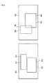
図5乃至図9は、テンプレートDB33に記憶されている配置テンプレートの例を示す図である。各配置テンプレートは、所定の枚数の画像を配置するときに用いられるテンプレートであり、配置される画像の枚数毎に、複数のテンプレートが用意されている。ここでは、所定の枚数の画像、例えば、1枚の画像を配置するための複数のテンプレートをまとめて表記するときは、配置テンプレート群と記述する。
5 to 9 are diagrams showing examples of arrangement templates stored in the
図5乃至図9にそれぞれ示す配置テンプレート群に含まれる、配置テンプレート131−1乃至131−3、配置テンプレート132−1乃至132−3、配置テンプレート133−1乃至133−3、配置テンプレート134−1乃至134−3、配置テンプレート135−1乃至135−3は、それぞれ付随する情報を有する。付随する情報は、例えば、背景テンプレート111と同じように、日時やイベントに関する情報である。 Arrangement templates 131-1 to 131-3, arrangement templates 132-1 to 132-3, arrangement templates 133-1 to 133-3, and arrangement template 134-1 included in the arrangement template groups shown in FIGS. Through 134-3 and the placement templates 135-1 through 135-3 each have associated information. The accompanying information is, for example, information related to the date and time and the event, like the background template 111.
図5に示した配置テンプレート131−1乃至131−3という3枚のテンプレートを含む配置テンプレート群は、1ページに1枚の画像が配置されるときの配置テンプレート131である。配置テンプレート131−1乃至131−3は、1枚の画像が配置されるという点で共通であるが、ページ内において、その1枚の画像が配置される位置や大きさはそれぞれ異なるように設定されているテンプレートである。 The arrangement template group including the three templates of the arrangement templates 131-1 to 131-3 shown in FIG. 5 is the arrangement template 131 when one image is arranged on one page. The arrangement templates 131-1 to 131-3 are common in that one image is arranged, but the positions and sizes of the one image in the page are set differently. Template.
図6に示した配置テンプレート132−1乃至132−3という3枚のテンプレートを含む配置テンプレート群は、1ページに2枚の画像が配置されるときの配置テンプレート132である。配置テンプレート132−1乃至132−3は、2枚の画像が配置されるという点で共通であるが、ページ内において、それらの2枚の画像がそれぞれ配置される位置やそれぞれの大きさは異なるように設定されているテンプレートである。 The arrangement template group including the three templates of the arrangement templates 132-1 to 132-3 shown in FIG. 6 is the arrangement template 132 when two images are arranged on one page. The arrangement templates 132-1 to 132-3 are common in that two images are arranged, but the positions and sizes of the two images are different in the page. It is a template set as follows.
図7に示した配置テンプレート133−1乃至133−3という3枚のテンプレートを含む配置テンプレート群は、1ページに3枚の画像が配置されるときの配置テンプレート133である。配置テンプレート133−1乃至133−3は、3枚の画像が配置されるという点で共通であるが、ページ内において、それらの3枚の画像がそれぞれ配置される位置やそれぞれの大きさは異なるように設定されているテンプレートである。 The arrangement template group including the three templates of the arrangement templates 133-1 to 133-3 shown in FIG. 7 is the arrangement template 133 when three images are arranged on one page. The arrangement templates 133-1 to 133-3 are common in that three images are arranged, but the positions and sizes of the three images are different in the page. It is a template set as follows.
図8に示した配置テンプレート134−1乃至134−3という3枚のテンプレートを含む配置テンプレート群は、1ページに4枚の画像が配置されるときの配置テンプレート134である。配置テンプレート134−1乃至134−3は、4枚の画像が配置されるという点で共通であるが、ページ内において、それらの4枚の画像がそれぞれ配置される位置やそれぞれの大きさは異なるように設定されているテンプレートである。 The arrangement template group including the three templates of the arrangement templates 134-1 to 134-3 shown in FIG. 8 is the arrangement template 134 when four images are arranged on one page. The arrangement templates 134-1 to 134-3 are common in that four images are arranged, but the positions and sizes of the four images in the page are different. It is a template set as follows.
図9に示した配置テンプレート135−1乃至135−3という3枚のテンプレートを含む配置テンプレート群は、1ページに5枚の画像が配置されるときの配置テンプレート135である。配置テンプレート135−1乃至135−3は、5枚の画像が配置されるという点で共通であるが、ページ内において、それらの5枚の画像がそれぞれ配置される位置やそれぞれの大きさは異なるように設定されているテンプレートである。 The arrangement template group including the three templates of the arrangement templates 135-1 to 135-3 shown in FIG. 9 is the arrangement template 135 when five images are arranged on one page. The arrangement templates 135-1 to 135-3 are common in that five images are arranged, but the positions and sizes of the five images in the page are different. It is a template set as follows.
各配置テンプレート131乃至135において、各画像が表示される位置と領域(大きさ)は、固定されている。例えば、配置テンプレート131―1には、1枚の画像が表示されるが、その画像が表示される位置と大きさは固定されており、仮に、表示される大きさよりも大きなサイズの画像が、配置テンプレート131−1に配置されるとしても、その画像が表示される領域の大きさが変更されることはない。よって、大きなサイズの画像が、配置テンプレートに貼り付けられる場合、その画像の一部が切り出され、配置テンプレートに貼り付けられ、表示される。 In each of the placement templates 131 to 135, the position and area (size) where each image is displayed are fixed. For example, one image is displayed on the placement template 131-1, but the position and size at which the image is displayed are fixed. If the image has a size larger than the displayed size, Even if the image is arranged in the arrangement template 131-1, the size of the area in which the image is displayed is not changed. Therefore, when a large-size image is pasted on the placement template, a part of the image is cut out, pasted on the placement template, and displayed.
図5乃至図9に示した配置テンプレート131乃至135は、一例であり、限定を示すものではない。また、ここでは、最大で5枚の画像が1ページに表示される場合まで例示したが、5枚以上の画像が1ページに表示される配置テンプレートを、テンプレートDB33に記憶させ、用いるようにしても勿論良い。しかしながら、1ページに表示される画像を多くすると、1枚あたりの表示領域が小さくなり、そのために画像が見づらくなる可能性があるので、あまり多くの画像を1ページに配置するような配置テンプレートを用意するのは好ましくない。
The arrangement templates 131 to 135 shown in FIGS. 5 to 9 are examples and do not indicate limitations. In addition, here, an example is shown up to the case where a maximum of five images are displayed on one page, but an arrangement template in which five or more images are displayed on one page is stored in the
テンプレート設定部72は、テンプレートDB33に記憶されている図5乃至図9に示した配置テンプレート131乃至135のうち、適切な配置テンプレートを設定する。適切な配置テンプレートを設定するための処理については後述するが、クラスタリングの結果が用いられて行われる。
The
図3のフローチャートの説明に戻り、ステップS13において、背景テンプレートが設定され、ステップS14において、配置テンプレートが設定されると、ステップS15において、画像の貼り付け処理が行われる。ステップS15において実行される画像の貼り付け処理についての詳細な説明は後述するが、設定されている配置テンプレートに、画像を貼り付け、背景テンプレートと合成する処理である。 Returning to the description of the flowchart of FIG. 3, when a background template is set in step S13 and an arrangement template is set in step S14, an image pasting process is performed in step S15. Although detailed description of the image pasting process executed in step S15 will be described later, this is a process of pasting an image on a set arrangement template and combining it with a background template.
このようにして、アルバム内の所定の1枚のページが作成される。ステップS11,S12の処理により、所定の1つのフォルダに対して行われ、その結果、1つのフォルダ内の複数の静止画像が、複数のクラスタに分類される。そして、1つのクラスタに対して、ステップS13乃至S15の処理が実行されることにより、アルバム内の1ページが作成される。 In this way, a predetermined page in the album is created. The processing in steps S11 and S12 is performed on a predetermined folder, and as a result, a plurality of still images in one folder are classified into a plurality of clusters. Then, the processing in steps S13 to S15 is executed for one cluster, so that one page in the album is created.
作成されたアルバム内の1ページの例を、図10に示す。図10の例において、ページ151には、背景テンプレート111−1と配置テンプレート135−1が設定されている。背景テンプレート111−1は、例えば、ページ151に配置されている5枚の画像のクラスタ情報と同じクラスタ情報を有する。また、配置テンプレート135−1によって、例えば、5枚の画像の配置が決定される。また、ページ151には、「○△□×2005」のコメントが表示されている。このようにユーザが、操作部19を操作することによって、ページ151の任意の位置に、任意のコメントを設定することができるようにしても良い。
An example of one page in the created album is shown in FIG. In the example of FIG. 10, a background template 111-1 and an arrangement template 135-1 are set on the
このように、アルバム内の所定の1ページは、設定された背景テンプレートの上に、設定された配置テンプレートに基づき画像が貼り付けられたような画像とされる。 Thus, a predetermined page in the album is an image in which an image is pasted on the set background template based on the set layout template.
また、配置テンプレートに配置される画像、換言すれば、アルバム内の所定の1ページに表示される画像は、静止画像であるが、その静止画像は、静止画像DB31に記憶されている静止画像だけでなく、動画像DB32に記憶されている動画像から抽出された静止画像が含まれるようにしても良い。
Further, an image arranged in the arrangement template, in other words, an image displayed on a predetermined page in the album is a still image, but the still image is only a still image stored in the
例えば、動画像DB32に記憶されている動画像のインデックスなどを作成するときに、ユーザに動画像の内容を示す画像として提供され、動画像の1シーンを示す静止画像が、アルバム内のページに表示されるようにしても良い。そのような静止画像は、サムネイル画像などと称されることがある。また、サムネイル画像は、1つの動画像から複数枚作成されることがあり、それらの複数枚のサムネイル画像の全てが、アルバムを構成するページ内に表示されるようにしても良いし、選択された1枚のサムネイル画像のみが表示されるようにしても良い。
For example, when creating an index or the like of a moving image stored in the moving
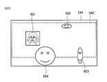
動画像から抽出された静止画像が表示されたときの、ページの画面例を図11に示す。図11において、ページ151’に表示されている3枚の静止画像のうち、静止画像161が、動画像から抽出された静止画像(サムネイル画像)である。この静止画像161は、動画像から抽出された静止画像であることをユーザに認識させるための表示として、“Video”というマーク162が、静止画像161の近傍に表示される。
FIG. 11 shows a screen example of a page when a still image extracted from a moving image is displayed. In FIG. 11, among the three still images displayed on the
このように、マーク162が表示されている静止画像161が、ユーザにより選択されると、その静止画像161の元の動画像の再生が開始される。ユーザにより選択されるとは、例えば、図示していないカーソルが、静止画像161上に位置しているときに、マウス(同じく不図示)がダブルクリックされるなど、所定の操作が行われることを意味する。
As described above, when the
また、ページ151’に表示されている静止画像171または静止画像172が選択された場合、その選択された静止画像171(静止画像172)が、拡大表示される。
When the
図3のフローチャートの説明に戻り、ステップS16において、全てのクラスタに対して処理が終了したか否かが判断される。ステップS16の処理を換言するならば、アルバム内の全てのページが作成されたか否かが判断される処理である。 Returning to the description of the flowchart of FIG. 3, in step S <b> 16, it is determined whether or not processing has been completed for all clusters. In other words, the process of step S16 is a process for determining whether all pages in the album have been created.
ステップS16において、全てのクラスタに対して処理は終了していないと判断された場合、ステップS13に処理が戻され、それ以降の処理が実行される。すなわち、次のページの作成が行われる。 If it is determined in step S16 that the process has not been completed for all clusters, the process is returned to step S13, and the subsequent processes are executed. That is, the next page is created.
一方、ステップS16において、全てのクラスタに対して処理が終了したと判断された場合、ステップS17に処理が進められる。ステップS17に処理が来るのは、アルバム内の全てのページの作成が終了された場合であり、換言すれば、アルバムが完成した場合である。よって、ステップS17においては、作成されたアルバムが、コンテンツDB34に記憶(保存)される。
On the other hand, if it is determined in step S16 that the processing has been completed for all clusters, the process proceeds to step S17. The processing comes to step S17 when the creation of all the pages in the album is completed, in other words, when the album is completed. Therefore, in step S17, the created album is stored (saved) in the
このようにして、アルバムが作成される。図12に、作成されたアルバムの構成の一例を示す。 In this way, an album is created. FIG. 12 shows an example of the configuration of the created album.
図12に示した例において、アルバム181は、ページ151乃至155の5ページで構成されている。アルバム181のページ151乃至155に配置されている画像は、同じフォルダ内に記憶されている画像である。ページ151乃至155には、それぞれ配置テンプレートによって決定される所定の数の画像が配置されている。
In the example shown in FIG. 12, the
次に、図3のフローチャートを参照して説明した各ステップの処理について、詳細な説明をする。 Next, the process of each step described with reference to the flowchart of FIG. 3 will be described in detail.
[クラスタリングの処理について]
まず、ステップS12において実行されるクラスタリングの処理について説明する。
[About clustering processing]
First, the clustering process executed in step S12 will be described.
本実施の形態において行われるクラスタリングの概念についてまず説明する。なお、以下に説明するクラスタリングの手法は、一例であり、本発明が、以下に説明するクラスタリングの手法のみに適用されることを意味するものではない。 First, the concept of clustering performed in the present embodiment will be described. Note that the clustering method described below is an example, and does not mean that the present invention is applied only to the clustering method described below.
図13は、画像のグループ(クラスタ)の例を示す図である。図13において、横軸は時間軸を示す。 FIG. 13 is a diagram illustrating an example of image groups (clusters). In FIG. 13, the horizontal axis indicates the time axis.
図13は、時刻t1乃至t12のそれぞれのタイミングにおいて撮影された画像p1乃至p12がクラスタリングの対象とされている場合の例を示している。例えば、静止画像DB31に記録されている静止画像と、動画像DB32に記録されている動画像から抽出された静止画像が、クラスタリングの対象とされる。図13の1つの四角形は1枚の画像を表す。
FIG. 13 shows an example in which the images p1 to p12 photographed at the respective timings from time t1 to t12 are targeted for clustering. For example, a still image recorded in the
画像処理装置1においては、それぞれの画像の撮影時刻の時間間隔が求められ、時間間隔の分布が、ある条件を満たす連続した画像から1つのクラスタが構成される。撮影されたそれぞれの画像には、EXIF(Exchangeable Image File Format)タグが属性情報として付加されており、このEXIFタグに含まれる撮影時刻の情報がクラスタリングに用いられる。 In the image processing apparatus 1, the time interval of the photographing time of each image is obtained, and one cluster is formed from continuous images whose time interval distribution satisfies a certain condition. Each photographed image is added with an exchangeable image file format (EXIF) tag as attribute information, and information on the photographing time included in the EXIF tag is used for clustering.
図13の例においては、クラスタを規定する条件として条件Aと条件Bが設定され、そのうちの条件Aにより、画像p1乃至p12全体からなる1つのクラスタが規定されている。条件Aにより規定されたクラスタにはイベント名「結婚式」が設定されている。 In the example of FIG. 13, a condition A and a condition B are set as conditions for defining a cluster, and one of the images p1 to p12 is defined by the condition A. The event name “wedding” is set in the cluster defined by the condition A.
クラスタリングの詳細については後述するが、「結婚式」のイベント名が設定されているクラスタは、例えば、画像p1乃至p12のそれぞれの画像の撮影時刻の時間間隔のばらつきの程度が、ある閾値より小さいことなどから規定されたものである。 Although details of clustering will be described later, in the cluster in which the event name “wedding” is set, for example, the degree of variation in the time interval of the shooting time of each of the images p1 to p12 is smaller than a certain threshold value. It is stipulated from things.
また、図13の例においては、条件Bにより、画像p1乃至p12のうちの画像p1乃至p3から1つのクラスタが規定され、画像p4乃至p7から1つのクラスタが規定されている。また、画像p8乃至p12から1つのクラスタが規定されている。 In the example of FIG. 13, one cluster is defined from the images p1 to p3 among the images p1 to p12 and one cluster is defined from the images p4 to p7. One cluster is defined from the images p8 to p12.
画像p1乃至p3からなるクラスタには「教会での挙式」、画像p4乃至p7からなるクラスタには「披露宴」、画像p8乃至p12からなるクラスタには「二次会」のイベント名がそれぞれ設定されている。 “Church Ceremony” is set for the cluster consisting of images p1 to p3, “Reception” is set for the cluster consisting of images p4 to p7, and “Secondary Party” is set for the cluster consisting of images p8 to p12. .
「教会での挙式」のイベント名が設定されているクラスタは、それを構成する画像p1乃至p3のそれぞれの撮影時刻の時間間隔のばらつきの程度が近いものであるのに対し、画像p3と、次に(時間軸上で次に)撮影時刻の時間間隔のばらつきの程度が近い画像のまとまりである画像p4乃至p7のうちの最初の画像である画像p4との時間間隔が比較的大きく、その部分で、撮影の頻度に変化があったと判断されたことから規定されたものである。 In the cluster in which the event name “Church Ceremony” is set, the image p3 and the images p1 to p3 constituting the cluster have the same degree of variation in the time interval of the photographing time, whereas the image p3, Next (next on the time axis), the time interval with the image p4 which is the first image among the images p4 to p7 which is a group of images with a similar degree of variation in the time interval of the photographing time is relatively large. This is specified because it was determined that there was a change in the frequency of shooting.
また、「披露宴」のイベント名が設定されているクラスタは、それを構成する画像p4乃至p7のそれぞれの撮影時刻の時間間隔のばらつきの程度が近いものであるのに対し、画像p7と、次に撮影時刻の時間間隔のばらつきの程度が近い画像のまとまりである画像p8乃至p12のうちの最初の画像である画像p8との時間間隔が比較的大きく、その部分で、撮影の頻度に変化があったと判断されたことから規定されたものである。 Also, in the cluster in which the event name “Reception Party” is set, the degree of variation in the time interval of the shooting time of each of the images p4 to p7 constituting the event is close, while the image p7 and the next In addition, the time interval with the image p8 which is the first image among the images p8 to p12, which is a group of images having a close variation in the time interval of the shooting time, is relatively large, and the frequency of shooting changes at that portion. It was specified because it was judged that there was.
「二次会」のイベント名が設定されているクラスタは、それを構成する画像p8乃至p12のそれぞれの撮影時刻の時間間隔のばらつきの程度が近いものであるのに対し、画像p12と、次に撮影時刻の時間間隔のばらつきの程度が近い画像のまとまりのうちの最初の画像との時間間隔が比較的大きく、その部分で、撮影の頻度に変化があったと判断されたことから規定されたものである。 In the cluster in which the event name “secondary party” is set, the degree of variation in the time interval of the photographing time of each of the images p8 to p12 constituting the cluster is close, whereas the image p12 is photographed next. It is specified because the time interval with the first image of a group of images with similar time interval variations is relatively large, and it was determined that there was a change in the frequency of shooting at that part. is there.
なお、「結婚式」、「教会での挙式」、「披露宴」、「二次会」のそれぞれのイベント名は、例えば、ユーザにより手動で設定されたものである。 The event names of “wedding”, “ceremony at church”, “banquet”, and “second party” are set manually by the user, for example.
このように、画像処理装置1においては、同じ対象の画像をクラスタリングする条件として複数の条件が設定され、それぞれの条件に基づいて、異なる粒度のクラスタが規定される。図13の例においては、条件Aは粒度の低い(粗い)クラスタを規定する条件であり、条件Bは条件Aより粒度の高い(細かい)クラスタを規定する条件である。 Thus, in the image processing apparatus 1, a plurality of conditions are set as conditions for clustering the same target image, and clusters of different granularities are defined based on the respective conditions. In the example of FIG. 13, the condition A is a condition that defines a cluster with a low particle size (coarse), and the condition B is a condition that defines a cluster with a particle size higher than the condition A (fine).
以上のようにして規定されたそれぞれのクラスタに含まれる画像は仮想的に1つのフォルダによりまとめて管理され、階層構造を有する形でユーザに提示される。 The images included in each cluster defined as described above are virtually managed together by one folder and presented to the user in a hierarchical structure.
図14は、階層構造の例を示す図である。 FIG. 14 is a diagram illustrating an example of a hierarchical structure.
図14の例においては、「私の思い出」の名前が設定されたフォルダの下位の階層のフォルダとして、条件Aにより規定される「結婚式」のイベント名が設定されたクラスタを表すフォルダと、「北海道旅行」のイベント名が設定されたクラスタを表すフォルダが示されている。 In the example of FIG. 14, a folder representing a cluster in which the event name of “wedding” defined by the condition A is set as a folder in a lower hierarchy of the folder in which the name of “my memory” is set; A folder representing a cluster with an event name of “Hokkaido Travel” is shown.
また、「結婚式」のイベント名が設定されたクラスタを表すフォルダの下位の階層のフォルダとして、条件Bにより規定される「教会での挙式」、「披露宴」、「二次会」のそれぞれのイベント名が設定されたクラスタを表すフォルダが示されている。 In addition, the event names of “ceremony at church”, “banquet”, and “second party” are defined as the folders below the folder representing the cluster in which the event name of “wedding” is set. A folder representing a cluster in which is set is shown.
さらに、「北海道旅行」のイベント名が設定されたクラスタを表すフォルダの下位の階層のフォルダとして、条件Bにより規定される「釧路湿原」、「札幌すすきの」、「稚内カニ」、「富良野」、「網走監獄」のそれぞれのイベント名が設定されたクラスタを表すフォルダが示されている。これらのフォルダにより表されるクラスタも、それぞれのクラスタを構成する画像の撮影時刻の時間間隔の分布により規定されたものである。 Furthermore, as a folder in the lower hierarchy of the folder representing the cluster set with the event name “Hokkaido Travel”, “Kushiro Marsh”, “Sapporo Susukino”, “Wakkanai Crab”, “Furano” A folder representing a cluster in which each event name of “Abashiri Prison” is set is shown. The clusters represented by these folders are also defined by the distribution of the time intervals of the shooting times of the images constituting each cluster.
このように、画像処理装置1においては、イベント毎にフォルダが作成され、作成されたフォルダにはそれぞれのイベントのときに撮影された画像が含められるから、ユーザは、階層構造を有するフォルダの中から所定のフォルダを選択することによって、イベ ント単位で画像を閲覧したり、整理したりすることができる。 As described above, in the image processing apparatus 1, a folder is created for each event, and an image taken at each event is included in the created folder. By selecting a predetermined folder from, you can view and organize images by event.
例えば、ユーザは、撮影して得られた画像を、図15の上方に示されるように単に時系列順に閲覧するのではなく、白抜き矢印の先に示されるように、フォルダf11,f12,f122,f211,f212,f22のそれぞれに含まれる画像の順序で、すなわち、好みの粒度のフォルダを選択して、好みの順序で、画像を閲覧することができる。 For example, the user does not simply browse images obtained by shooting in chronological order as shown in the upper part of FIG. 15, but as shown at the end of the white arrows, the folders f11, f12, and f122. , F211, f212, and f22, that is, by selecting a folder with a desired granularity and browsing the images in the desired order.
図15の1つの楕円は1つのフォルダを表す。図15において、撮影して得られた画像全体がフォルダf1に含まれる画像とフォルダf2に含まれる画像に分けられ、このうちのフォルダf1に含まれる画像は、さらにフォルダf11に含まれる画像とフォルダf12に含まれる画像に分けられる。フォルダf11に含まれる画像は、フォルダf111に含まれる画像とフォルダf112に含まれる画像に分けられ、フォルダf12に含まれる画像は、フォルダf121に含まれる画像とフォルダf122に含まれる画像に分けられる。同様に、フォルダf2に含まれる画像も下位の階層のフォルダに含まれる画像に分けられる。 One ellipse in FIG. 15 represents one folder. In FIG. 15, the entire image obtained by photographing is divided into an image included in the folder f1 and an image included in the folder f2, and the image included in the folder f1 is further divided into an image and a folder included in the folder f11. It is divided into images included in f12. An image included in the folder f11 is divided into an image included in the folder f111 and an image included in the folder f112, and an image included in the folder f12 is divided into an image included in the folder f121 and an image included in the folder f122. Similarly, the images included in the folder f2 are also divided into images included in lower-level folders.
図16は、画像処理装置1内で、クラスタリングの処理を実行する部分を図1または図2に示した画像処理装置1の構成から抽出するとともに、クラスタリングの処理を実行するうえで必要とされる部分を追加した図である。 FIG. 16 is necessary for executing the clustering process while extracting the portion for executing the clustering process in the image processing apparatus 1 from the configuration of the image processing apparatus 1 shown in FIG. 1 or 2. It is the figure which added the part.
図16に示したクラスタリングの処理を実行する部分は、静止画像DB31、動画像DB32、演算部71(クラスタリング部91、階層決定部92)、タグ読み取り部201、条件設定部202、および、イベント名設定部203を含む構成されている。
The parts that execute the clustering process shown in FIG. 16 are a
静止画像DB31には、撮影時刻、撮影日などの情報を含むEXIFタグが、撮影された画像と対応付けられて記録されている。
In the
タグ読み取り部201は、画像のクラスタリングを行うとき、静止画像DB31に記録されているEXIFタグから、クラスタリングの対象とするそれぞれの画像の撮影時刻を読み出し、読み出した撮影時刻を演算部71に出力する。また、タグ読み取り部201は、後述するように、ユーザからの指示があった場合など、動画像DB32に記録されている動画像の撮影時刻に関する情報を読み出し、読み出した撮影時刻を演算部71に出力する。
When performing image clustering, the
画像のクラスタリングは、1枚の画像の撮影が行われる毎に行われるようにしてもよいし、ユーザによりクラスタリングを行うことが指示されたときなどの所定のタイミングで行われるようにしてもよい。本実施の形態においては、アルバムが作成されるタイミングで行われるとする(ステップS12の処理として行われるとする)。 Image clustering may be performed each time a single image is taken, or may be performed at a predetermined timing such as when the user instructs clustering. In the present embodiment, it is assumed that it is performed at the timing when the album is created (assumed to be performed as the process of step S12).
演算部71はクラスタリング部91と階層決定部92から構成される。クラスタリング部91は、コンテンツDB34に記録されているクラスタデータを取得し、取得したクラスタデータと、タグ読み取り部201から供給された撮影時刻に基づいて画像のクラスタリング を行う。例えば、過去にクラスタリングが行われた画像も含めて、画像全体が二分木構造を有する形で管理されるクラスタリング結果がクラスタリング部91により取得される。
The
コンテンツDB34に記録されているクラスタデータには、それまでに求められた、それぞれの画像がどのクラスタに属するのかを表す情報や、画像全体の二分木構造を表す情報が含まれる。
The cluster data recorded in the
階層決定部92は、クラスタリング部91により取得されたクラスタリング結果である二分木構造を表す情報に基づいて、条件設定部202により設定された条件にあうクラスタを決定する。例えば、それぞれのクラスタがどの画像を含むのかを表す情報、あるいは、それぞれの画像がどのクラスタに属するのかを表す情報などが階層決定部92により取得され、画像全体の二分木構造を表すとともに、最終的なクラスタリングの結果を表すクラスタデータとしてコンテンツDB34に記録される。
The
条件設定部202は、クラスタを規定する条件であるグループ化条件を設定し、階層決定部92に出力する。グループ化条件は、あらかじめ用意される複数の条件の中からユーザにより選択されることによって設定されるようにしてもよいし、複数のクラスタを1つのクラスタに結合したり、1つのクラスタを複数のクラスタに分割したりするなどの、ユーザにより行われたクラスタの編集の履歴が管理されている場合、ユーザが好むと考えられるクラスタの粒度が編集の履歴を用いて学習により求められ、そのような粒度のクラスタを得ることができるような条件が動的に設定されるようにしてもよい。
The
コンテンツDB34は、階層決定部92から供給されたクラスタデータを、静止画像DB31に記録されている画像データと対応付けて記録する。クラスタリング結果により表されるそれぞれのクラスタには、イベント名設定部203から供給されたイベント名も対応付けて記録される。このように、画像処理装置1においては、画像データ本体とクラスタデータは別々に管理されるようになされている。
The
イベント名設定部203は、ユーザにより設定されたイベント名をコンテンツDB34に出力し、クラスタと対応付けて記録させる。また、イベント名設定部203は、ユーザによりイベント名が設定されない場合、コンテンツDB34に記録されているクラスタデータを用いてそれぞれのクラスタに属する画像を識別し、識別した画像の撮影日や撮影時間帯(午前、午後など)を含むイベント名をクラスタと対応付けて記録させる。
The event
ここで、演算部71により行われる処理の詳細について説明する。
Here, details of processing performed by the
例えば、100枚の画像p1乃至p100をクラスタリングの対象として、それらの画像をイベントクラスタA(グループ化条件Aを満たす画像のクラスタ)と、サブイベントクラスタB(グループ化条件Bを満たす画像のクラスタ)に分ける処理について説明する 。 For example, with 100 images p1 to p100 as clustering targets, these images are classified into event cluster A (cluster of images satisfying grouping condition A) and sub-event cluster B (cluster of images satisfying grouping condition B). The process divided into two will be described.
はじめに、図17乃至図25を参照して、クラスタリング部91により行われる二分木構造の作成について説明する。
First, the creation of a binary tree structure performed by the
図17乃至図25において、「p」の文字と数字がその中に書かれている1つの円は1枚の画像を表し、「n」の文字と数字がその中に書かれている1つの円は1つのノードを表す。また、図の右方は、左方より時間的に後の方向であるものとする。なお、ここでは、画像p1乃至p100を、撮影時刻順(画像p1が一番古く、画像p100が一番新しいデータ)にクラスタリングの対象とする場合について説明する。画像p1とp2をクラスタリングの対象とした後(二分木構造に組み込んだ後)で、画像p1よりも新しく、画像p2より古い画像p3を新たにクラスタリングの対象とするように、撮影時刻順にではなく、それぞれの画像を対象として行われるクラスタリングについては後述する。 In FIG. 17 to FIG. 25, one circle in which letters “p” and numbers are written represents one image, and one circle in which letters “n” and numbers are written. A circle represents one node. Also, the right side of the figure is assumed to be a time later than the left side. Here, a case will be described in which images p1 to p100 are clustered in order of photographing time (image p1 is the oldest data and image p100 is the newest data). After the images p1 and p2 are targeted for clustering (after being incorporated into the binary tree structure), the image p3 that is newer than the image p1 and older than the image p2 is newly targeted for clustering, not in order of shooting time. The clustering performed for each image will be described later.
クラスタリングがまだ行われていない状態で、最初の撮影により得られた画像p1がツリーに挿入されたとき(クラスタリングの対象とされたとき)、初期の状態ではツリーのルートとなるノードが存在しないから、図17に示されるように、画像p1自身がルートノードとなる。 When clustering has not yet been performed and the image p1 obtained by the first shooting is inserted into the tree (when it is targeted for clustering), there is no node that is the root of the tree in the initial state. As shown in FIG. 17, the image p1 itself becomes a root node.
画像p1に続けて撮影された画像p2がツリーに挿入されたとき、図18に示されるように、ノードn1が新たに作られ、画像p2の撮影時刻は画像p1の撮影時刻より後であるから、ノードn1には、画像p1が左の子ノードとして連結され、画像p2が右の子ノードとして連結される。ノードn1は画像p1に代えてルートノードとなる。 When an image p2 photographed subsequent to the image p1 is inserted into the tree, a node n1 is newly created as shown in FIG. 18, and the photographing time of the image p2 is later than the photographing time of the image p1. , Node n1 is connected with image p1 as a left child node and image p2 is connected as a right child node. The node n1 becomes a root node instead of the image p1.
ノードn1の最小時刻として画像p1の撮影時刻が記録され、最大時刻として画像p2の撮影時刻が記録される。ノードの時刻として、そのノードを親のノードとする2つの子ノードの撮影時刻の平均値(中間の時刻)が記録されるようにしてもよい。 The shooting time of the image p1 is recorded as the minimum time of the node n1, and the shooting time of the image p2 is recorded as the maximum time. As the time of a node, an average value (intermediate time) of photographing times of two child nodes having the node as a parent node may be recorded.
画像p2に続けて撮影された画像p3がツリーに挿入され、図19に示されるように、画像p3の撮影時刻と画像p2の撮影時刻の時間間隔tdp2p3が、画像p2の撮影時刻と画像p1の撮影時刻の時間間隔tdp1p2より小さいとき、図20に示されるように、ノードn2が新たに作られ、ノードn2には、その左の子ノードとして画像p2が連結され、右の子ノードとして画像p3が連結される。また、ノードn2が、画像p2の代わりに右の子ノードとしてノードn1に連結される。 The image p3 taken subsequent to the image p2 is inserted into the tree, and as shown in FIG. 19, the time interval td p2p3 between the shooting time of the image p3 and the shooting time of the image p2 is the shooting time of the image p2 and the image p1. 20 is smaller than the time interval td p1p2 , the node n2 is newly created as shown in FIG. 20, and the image p2 is connected to the node n2 as its left child node, and as the right child node. The image p3 is connected. Further, the node n2 is connected to the node n1 as a right child node instead of the image p2.
ノードn2の最小時刻として画像p2の撮影時刻が記録され、最大時刻として画像p3の撮影時刻が記録される。また、このとき、ノードn2の親のノードであるノードn1の最大時刻が画像p3の撮影時刻で上書きされる。 The shooting time of the image p2 is recorded as the minimum time of the node n2, and the shooting time of the image p3 is recorded as the maximum time. At this time, the maximum time of the node n1, which is the parent node of the node n2, is overwritten with the shooting time of the image p3.
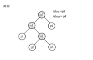
画像p3に続けて撮影された画像p4がツリーに挿入され、図21に示されるように、画像p4の撮影時刻と画像p3の撮影時刻の時間間隔tdp3p4が、画像p3の撮影時刻と画像p2の撮影時刻の時間間隔tdp2p3より大きく、かつ、画像p4の撮影時刻とノードn2の最大時刻の時間間隔tdn2maxp4が、ノードn2の最小時刻と画像p1の撮影時刻の時間間隔tdp1n2minより大きいとき、図22に示されるように、ノードn3が新たにルートノードとして作られる。また、ノードn3には、その左の子ノードとしてノードn1が連結され、右の子ノードとして画像p4が連結される。 An image p4 taken after the image p3 is inserted into the tree, and as shown in FIG. 21, the time interval td p3p4 between the shooting time of the image p4 and the shooting time of the image p3 is the shooting time of the image p3 and the image p2. greater than the time interval td p2p3 shooting time, and the maximum time interval td N2maxp4 the photographing time and the node n2 of the image p4 is, when the time intervals greater than td P1n2min the capture time of the minimum time and the image p1 of the node n2 As shown in FIG. 22, a node n3 is newly created as a root node. In addition, the node n3 is connected with the node n1 as the left child node and the image p4 is connected as the right child node.
ノードn3の最小時刻としてノードn1の最小時刻が記録され、最大時刻として画像p4の撮影時刻が記録される。 The minimum time of the node n1 is recorded as the minimum time of the node n3, and the shooting time of the image p4 is recorded as the maximum time.
画像p4に続けて撮影された画像p5がツリーに挿入され、図23に示されるように、画像p5の撮影時刻と画像p4の撮影時刻の時間間隔tdp4p5より、画像p4の撮影時刻とノードn1の最大時刻の時間間隔tdn1maxp4の方が大きいとき、図24に示されるように、ノードn4が新たに作られる。また、ノードn4には、その左の子ノードとして画像p4が連結され、右の子ノードとして画像p5が連結される。さらに、ノードn4が、画像p4の代わりに右の子ノードとしてノードn3に連結される。 An image p5 taken subsequent to the image p4 is inserted into the tree, and as shown in FIG. 23, the shooting time of the image p4 and the node n1 from the time interval td p4p5 between the shooting time of the image p5 and the shooting time of the image p4. When the time interval td n1maxp4 of the maximum time is larger, a node n4 is newly created as shown in FIG. Further, the node n4 is connected with the image p4 as a left child node thereof and with the image p5 as a right child node. Further, the node n4 is connected to the node n3 as a right child node instead of the image p4.
ノードn4の最小時刻として画像p4の撮影時刻が記録され、最大時刻として画像p5の撮影時刻が記録される。また、このとき、ノードn4の親のノードであるノードn3の最大時刻が画像p5の撮影時刻で上書きされる。 The shooting time of the image p4 is recorded as the minimum time of the node n4, and the shooting time of the image p5 is recorded as the maximum time. At this time, the maximum time of the node n3 that is the parent node of the node n4 is overwritten with the shooting time of the image p5.
この時点で、画像p1乃至p5の5枚の画像を含むノードn1乃至n4から二分木構造が形成された状態になる。 At this point, the binary tree structure is formed from the nodes n1 to n4 including the five images p1 to p5.
それぞれのノードに含まれる画像は、それぞれのノードに直接に、または他のノードを介して間接的に連結される画像であるから、図24に示されるようなツリーが作成されているとき、ノードn3に含まれる画像は画像p1乃至p5の5枚の画像となり、ノードn1に含まれる画像は画像p1乃至p3の3枚の画像となる。また、ノードn2に含まれる画像は画像p2およびp3の2枚の画像となり、ノードn4に含まれる画像は画像p4およびp5の2枚の画像となる。 Since the image included in each node is an image that is directly connected to each node or indirectly connected to another node, when the tree as shown in FIG. The images included in n3 are five images p1 to p5, and the images included in the node n1 are three images p1 to p3. The image included in the node n2 is two images p2 and p3, and the image included in the node n4 is two images p4 and p5.
このように、画像が新たに挿入される毎に、撮影時刻の時間間隔のより小さい画像同士、または、撮影時刻と設定された時刻の時間間隔のより小さい画像とノードが、同じノードにぶらさがるように連結されていく。 In this way, each time a new image is inserted, images having a smaller time interval between shooting times or images and nodes having a smaller time interval between the shooting time and the set time are hung on the same node. It will be connected to.
撮影が繰り返し行われ、画像p6乃至p100がツリーに挿入されたときも同様にして処理が行われ、最終的に、ルートノードnrootに画像p1乃至p100が含まれる、図25に示されるような二分木構造が得られる。 When shooting is repeated and images p6 to p100 are inserted into the tree, the same processing is performed, and finally the images p1 to p100 are included in the root node n root as shown in FIG. A binary tree structure is obtained.
次に、図26乃至図32を参照して、階層決定部92により行われるグループ化条件に基づくクラスタリングについて説明する。
Next, clustering based on the grouping condition performed by the
階層決定部92においては、二分木構造内のそれぞれのノードが注目され、ノード内の全ての画像の撮影時刻の時間間隔の標準偏差sdが下式(1)により算出される。
In the

Nは画像の撮影時刻の時間間隔の数であり、「ノードに含まれる画像の数−1」で表される。tdnは、N個の時間間隔のうちの、時間的に先のものから見てn番目の時間間隔である。「 ̄」が付されたtdはノード内の時間間隔tdの平均値である。 N is the number of time intervals of image capturing time, and is represented by “the number of images included in a node−1”. td n is the nth time interval of N time intervals when viewed from the previous time point. Td with “ ̄” is an average value of the time interval td in the node.
また、注目するノードを親のノードとする子ノード間の時間間隔の偏差dev(子ノード間の時間間隔と、撮影時刻の時間間隔の平均との差の絶対値)が下式(2)により算出される。 Further, the deviation dev (the absolute value of the difference between the time interval between the child nodes and the average of the time interval of the photographing time) between the child nodes having the node of interest as the parent node is expressed by the following equation (2). Calculated.
Nは画像の撮影時刻の時間間隔の数であり、「ノードに含まれる画像の数−1」で表される。tdcは子ノード間の時間間隔である。「 ̄」が付されたtdはノード内の時間間隔tdの平均値である。なお、子ノード間の時間間隔とは、注目するノードを親のノードとする2つの子ノードのうちの時間的に先の子ノードに含まれる時間的に最後の画像の撮影時刻と、時間的に後の子ノードに含まれる時間的に最初の画像の撮影時刻の時間間隔である。具体例については後述する。 N is the number of time intervals of image capturing time, and is represented by “the number of images included in a node−1”. td c is the time interval between child nodes. Td with “ ̄” is an average value of the time interval td in the node. Note that the time interval between child nodes is the time at which the last image in time included in the child node that is the parent of the two child nodes having the node of interest as the parent node is temporally The time interval of the shooting time of the first image included in the subsequent child node. Specific examples will be described later.
さらに、式(2)により算出された偏差devの、式(1)により算出された標準偏差sdに対する比が、分割パラメータthとして、注目するノードに設定される。分割パラメータthは下式(3)で表され、注目するノードを親のノードとする子ノードを、それぞれ異なるクラスタに属するものとして分割するか否かを判断する基準となるパラメータである。 Further, the ratio of the deviation dev calculated by the equation (2) to the standard deviation sd calculated by the equation (1) is set as the division parameter th at the node of interest. The division parameter th is expressed by the following equation (3), and is a parameter serving as a reference for determining whether or not to divide a child node whose parent node is the node of interest as belonging to different clusters.
ここで、上式により求められる値について図26を参照して具体的に説明する。 Here, the value obtained by the above equation will be specifically described with reference to FIG.
図26は、クラスタリング部91により作成された二分木構造全体のうちの一部の、図24と同じ範囲の構造を示す図である。
FIG. 26 is a diagram showing a part of the entire binary tree structure created by the
図26において、td1は、画像p1の撮影時刻と画像p2の撮影時刻の時間間隔であり、td2は、画像p2の撮影時刻と画像p3の撮影時刻の時間間隔である。また、td3は、画像p3の撮影時刻と画像p4の撮影時刻の時間間隔であり、td4は、画像p4の撮影時刻と画像p5の撮影時刻の時間間隔である。 In FIG. 26, td 1 is the time interval between the shooting time of the image p1 and the shooting time of the image p2, and td 2 is the time interval between the shooting time of the image p2 and the shooting time of the image p3. Td 3 is a time interval between the shooting time of the image p3 and the shooting time of the image p4, and td 4 is a time interval between the shooting time of the image p4 and the shooting time of the image p5.
例えば、図26のうちのルートノードに最も近いノードであるノードn3が注目されている場合、はじめに、式(1)にそれぞれの値が代入され、標準偏差sdは下式(4)で表される。また、撮影時刻の時間間隔の平均値は下式(5)で表される。 For example, when attention is paid to the node n3 that is the node closest to the root node in FIG. 26, first, each value is substituted into the equation (1), and the standard deviation sd is expressed by the following equation (4). The Moreover, the average value of the time interval of imaging time is represented by the following formula (5).
偏差devは下式(6)で表される。 The deviation dev is expressed by the following equation (6).
すなわち、注目するノードn3を親のノードとする2つの子ノードはノードn1とn4であり、そのうちの時間的に先のノードn1に含まれる時間的に最後の画像p3の撮影時刻と、時間的に後のノードn4に含まれる時間的に最初の画像4の撮影時刻の時間間隔td3がノードn1とノードn4の時間間隔であり、それが、ノードn3に注目したときの偏差devの算出に用いられる。
That is, two child nodes having the target node n3 as a parent node are the nodes n1 and n4, and the time of the last image p3 included in the previous node n1 in time and the time The time interval td3 of the photographing time of the
式(4)により算出された標準偏差sdと、式(6)により算出された偏差devから、ノードn3に注目したときの分割パラメータthが算出され、ノードn3に設定される。 From the standard deviation sd calculated by the equation (4) and the deviation dev calculated by the equation (6), the division parameter th when attention is paid to the node n3 is calculated and set to the node n3.
以上のようにして全てのノードに対する分割パラメータの設定が終了したとき、階層決定部92においては、次に、グループ化条件としての閾値が設定される。
When the setting of the division parameters for all the nodes is completed as described above, the
例えば、グループ化条件Aとして閾値aが設定され、グループ化条件Bとして閾値bが設定された場合、「a=3.0」、「b=2.6」などのように、「a>b」の条件を満たすときには、図27に示されるように、「グループ化条件Aにより規定されるクラスタ>グループ化条件Bにより規定されるクラスタ」となる(グループ化条件Aにより規定されるクラスタの中に、グループ化条件Bにより規定されるクラスタがいくつかできることになる)。 For example, when the threshold value a is set as the grouping condition A and the threshold value b is set as the grouping condition B, “a> b” such as “a = 3.0”, “b = 2.6”, etc. 27, as shown in FIG. 27, “cluster defined by grouping condition A> cluster defined by grouping condition B” (in the cluster defined by grouping condition A) Thus, several clusters defined by the grouping condition B can be created).
図27の例においては、対象となる画像全体が、グループ化条件Aによりグループg1とg2の2つのクラスタに分けられ、グループ化条件Bによりグループg3乃至g7の5つのクラスタに分けられている。 In the example of FIG. 27, the entire target image is divided into two clusters of groups g 1 and g 2 according to the grouping condition A, and is divided into five clusters of groups g 3 to g 7 according to the grouping condition B. It has been.
すなわち、後述するように、設定されている分割パラメータの値が閾値より大きい場合に、その分割パラメータが設定されているノードの部分がクラスタの境界部分となるから、閾値が大きいほど、そのノードの部分はクラスタの境界部分となりにくく、従って、全体として見たときにクラスタの粒度は粗くなる。反対に、閾値が小さいほど、そのノードの部分はクラスタの境界部分となりやすく、従って、全体として見たときにクラスタの粒度は細かくなる。 That is, as will be described later, when the value of the set partition parameter is larger than the threshold, the portion of the node for which the partition parameter is set becomes the boundary portion of the cluster. The portion is unlikely to become a boundary portion of the cluster, and therefore the cluster granularity becomes coarse when viewed as a whole. On the other hand, the smaller the threshold value, the more likely the node part becomes the boundary part of the cluster, and therefore the granularity of the cluster becomes finer when viewed as a whole.
なお、ある画像の撮影時刻と、次に撮影された画像の撮影時刻の時間間隔が30分以上ある場合(時間間隔td>30min)や1日以上ある場合(時間間隔td>1day)、その時間間隔のある部分がクラスタの境界部分となるようなグループ化条件、いわば、1つのクラスタに含まれる画像の撮影時刻の時間間隔の上限を規定するようなグループ化条件が設定されるようにしてもよい。これにより、撮影時刻の時間間隔が30分、あるいは1日以上ある画像同士はそれぞれ異なるクラスタに含まれる画像となる。 When the time interval between the shooting time of an image and the shooting time of the next image is 30 minutes or more (time interval td> 30 min) or more than 1 day (time interval td> 1 day), the time A grouping condition may be set so that a part having an interval becomes a boundary part of the cluster, that is, a grouping condition that defines an upper limit of the time interval of photographing times of images included in one cluster. Good. As a result, images having a time interval of the photographing time of 30 minutes or more than one day are included in different clusters.
グループ化条件としての閾値が設定された後、階層決定部92においては、次に、設定された閾値と、上述したようにしてそれぞれのノードに設定された分割パラメータthに基づいてそれぞれのノードに分割フラグが設定される。
After the threshold value as the grouping condition is set, the
例えば、分割パラメータthが、グループ化条件Aとして設定された閾値aを越えるノードには1の値のグループA分割フラグが設定され、閾値aを越えないノードには0の値のグループA分割フラグが設定される。 For example, a group A division flag having a value of 1 is set for a node whose division parameter th exceeds the threshold a set as the grouping condition A, and a group A division flag having a value of 0 is set for a node that does not exceed the threshold a. Is set.
分割フラグとして1の値が設定されていることは、その分割フラグが設定されているノ ードを親のノードとする子ノード間の時間間隔が、注目しているノード内全体の画像の撮影時刻の時間間隔より比較的大きいことを表す。反対に、分割フラグとして0の値が設定されていることは、その分割フラグが設定されているノードを親のノードとする子ノード間の時間間隔が、注目しているノード内全体の画像の撮影時刻の時間間隔とあまり変わらないことを表す。 When a value of 1 is set as the division flag, the time interval between the child nodes whose parent node is the node for which the division flag is set is an image of the entire image in the node of interest. Indicates that it is relatively larger than the time interval. On the other hand, when the value of 0 is set as the division flag, the time interval between the child nodes whose parent node is the node for which the division flag is set is the entire image in the node of interest. This means that it is not much different from the time interval of the shooting time.
グループA分割フラグの値の設定が終了したとき、二分木構造内のノードが昇順で(葉から根の方向に順に)注目され、子ノードの時間間隔がノード内全体の画像の撮影時刻の時間間隔より比較的大きいノード、すなわち、グループA分割フラグとして1の値が設定されているノードを境界として画像が区切られ、グループ化条件Aによりクラスタが規定される。 When setting of the value of the group A split flag is completed, the nodes in the binary tree structure are noticed in ascending order (in order from the leaves to the roots), and the time interval of the child nodes is the time of the imaging time of the entire image in the node An image is segmented with a node that is relatively larger than the interval, that is, a node having a value of 1 set as the group A division flag as a boundary, and a cluster is defined by the grouping condition A.
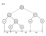
図28はグループA分割フラグの設定の例を示す図である。 FIG. 28 is a diagram showing an example of setting the group A division flag.
図28の例においては、ルートノードに最も近いノードであるノードn10には、ノードn11とn12がそれぞれ左右の子ノードとして連結され、ノードn11には、ノードn13とn14がそれぞれ左右の子ノードとして連結される。また、ノードn12には、ノードn15とn16がそれぞれ左右の子ノードとして連結され、ノードn14には、ノードn17とn18がそれぞれ左右の子ノードとして連結される。 In the example of FIG. 28, nodes n11 and n12 are connected as left and right child nodes to node n10 which is the node closest to the root node, and nodes n13 and n14 are respectively connected as left and right child nodes to node n11. Connected. Nodes n12 and n16 are connected to the node n12 as left and right child nodes, respectively, and nodes n17 and n18 are connected to the node n14 as left and right child nodes, respectively.
また、図28の例においては、これらのノードのうちのノードn10,n11,n12,n14のそれぞれにグループA分割フラグとして1の値が設定されており、それらのノードの部分を境界として、太線で示されるようにクラスタが分けられる。 In the example of FIG. 28, a value of 1 is set as the group A division flag in each of the nodes n10, n11, n12, and n14 out of these nodes, and the bold line The cluster is divided as shown in FIG.
なお、図28の右方に示されるように、ノードn13は画像p1乃至p17を含むノードであり、ノードn17は画像p18乃至p30を含むノードである。また、ノードn18は画像p31乃至p68を含むノードであり、ノードn15は画像p69乃至p93を含むノードである。ノードn16は画像p94乃至p100を含むノードである。 As shown on the right side of FIG. 28, the node n13 is a node including images p1 to p17, and the node n17 is a node including images p18 to p30. The node n18 is a node including images p31 to p68, and the node n15 is a node including images p69 to p93. Node n16 is a node including images p94 to p100.
従って、グループA分割フラグの値として1が設定されているノードの部分を境界としてクラスタが分けられた場合、いまクラスタリングの対象とされている画像p1乃至p100は、図29に示されるようなそれぞれのクラスタ(イベントクラスタA)に分けられる。 Therefore, when a cluster is divided with a node portion having a group A division flag value of 1 as a boundary, the images p1 to p100 that are currently targeted for clustering are as shown in FIG. Cluster (event cluster A).
すなわち、ノードn13に含まれる画像p1乃至p17からクラスタA1が構成され、ノードn17に含まれる画像p18乃至p30からクラスタA2が構成される。 That is, the cluster A 1 is configured from the images p1 to p17 included in the node n13, and the cluster A 2 is configured from the images p18 to p30 included in the node n17.
また、ノードn18に含まれる画像p31乃至p68からクラスタA3が構成され、ノードn15に含まれる画像p69乃至p93からクラスタA4が構成される。さらに、ノードn16に含まれる画像p94乃至p100からクラスタA5が構成される。 Further, a cluster A 3 is composed of the images p31 to p68 included in the node n18, and a cluster A 4 is composed of the images p69 to p93 included in the node n15. Further, a cluster A 5 is composed of the images p94 to p100 included in the node n16.
以上のようにしてグループ化条件Aに基づくクラスタリングが行われ、グループ化条件Aにより規定されるそれぞれのクラスタがどの範囲の画像を含むのかを表す情報、あるいは、それぞれの画像がどのクラスタに属するのかを表す情報などが、グループ化条件Aに基づくクラスタリング結果として取得される。 As described above, clustering based on the grouping condition A is performed, information indicating which range of images each cluster defined by the grouping condition A includes, or which cluster each image belongs to Is obtained as a clustering result based on the grouping condition A.
グループ化条件Aに基づくクラスタリングが行われたとき、同様にして、グループ化条件Bに基づくグループ分けが行われる。 When clustering based on the grouping condition A is performed, grouping based on the grouping condition B is performed in the same manner.
すなわち、階層決定部92においては、分割パラメータthが、グループ化条件Bとして 設定された閾値bを越えるノードには1の値のグループB分割フラグが設定され、閾値bを越えないノードには0の値のグループB分割フラグが設定される。
That is, in the
グループB分割フラグの値の設定が終了したとき、二分木構造内のノードが昇順で注目され、子ノードの時間間隔がノード内全体の画像の撮影時刻の時間間隔より比較的大きいノード、すなわち、グループB分割フラグとして1の値が設定されているノードを境界として画像が区切られ、グループ化条件Bによりクラスタが規定される。 When the setting of the value of the group B split flag is finished, the nodes in the binary tree structure are noticed in ascending order, and the time interval of the child nodes is relatively larger than the time interval of the photographing time of the entire image in the node, that is, An image is divided with a node having a value of 1 set as the group B division flag as a boundary, and a cluster is defined by the grouping condition B.
図30はグループB分割フラグの設定の例を示す図である。 FIG. 30 is a diagram showing an example of setting the group B division flag.
図30の例においては、ルートノードに最も近いノードであるノードn10には、ノードn11が左の子ノードとして連結され、ノードn11には、ノードn13とn14がそれぞれ左右の子ノードとして連結される。また、ノードn14には、ノードn17とn18がそれぞれ左右の子ノードとして連結され、ノードn17には、ノードn19とn20がそれぞれ左右の子ノードとして連結される。さらに、ノードn18には、ノードn21とn22がそれぞれ左右の子ノードとして連結され、ノードn19には、ノードn23とn24がそれぞれ左右の子ノードとして連結される。 In the example of FIG. 30, the node n10, which is the node closest to the root node, is connected to the node n11 as the left child node, and the nodes n11 are connected to the nodes n13 and n14 as the left and right child nodes, respectively. . Further, nodes n17 and n18 are connected to the node n14 as left and right child nodes, respectively, and nodes n19 and n20 are connected to the node n17 as left and right child nodes, respectively. Further, nodes n21 and n22 are connected to the node n18 as left and right child nodes, respectively, and nodes n23 and n24 are connected to the node n19 as left and right child nodes, respectively.
また、図30の例においては、これらのノードのうちのノードn10,n11,n14,n17,n18,n19のそれぞれにグループB分割フラグとして1の値が設定されており、それらのノードの部分を境界として、太線で示されるようにクラスタが分けられる。 In the example of FIG. 30, a value of 1 is set as the group B division flag in each of the nodes n10, n11, n14, n17, n18, and n19 among these nodes. As a boundary, clusters are divided as shown by bold lines.
なお、図30の右側に示されるように、ノードn13は画像p1乃至p17を含むノードであり、ノードn23は画像p18乃至p21を含むノードである。また、ノードn24は画像p22乃至p26を含むノードであり、ノードn20は画像p27乃至p30を含むノードである。ノードn21は画像p31乃至p57を含むノードであり、ノードn22は画像p58乃至p68を含むノードである。 As shown on the right side of FIG. 30, node n13 is a node including images p1 to p17, and node n23 is a node including images p18 to p21. The node n24 is a node including images p22 to p26, and the node n20 is a node including images p27 to p30. The node n21 is a node including images p31 to p57, and the node n22 is a node including images p58 to p68.
従って、グループB分割フラグの値として1が設定されているノードの部分を境界としてクラスタが分けられた場合、いまクラスタリングの対象とされている画像p1乃至p100のうちの画像p1乃至p68は、図31に示されるようなそれぞれのクラスタ(サブイベントクラスタB)に分けられる。 Therefore, when a cluster is divided with the boundary of a node portion where 1 is set as the value of the group B division flag, the images p1 to p68 among the images p1 to p100 that are currently targeted for clustering are shown in FIG. It is divided into respective clusters (sub-event cluster B) as shown in FIG.
すなわち、ノードn13に含まれる画像p1乃至p17からクラスタB1が構成され、ノードn23に含まれる画像p18乃至p21からクラスタB2が構成される。 That is, a cluster B 1 is configured from the images p1 to p17 included in the node n13, and a cluster B 2 is configured from the images p18 to p21 included in the node n23.
また、ノードn24に含まれる画像p22乃至p26からクラスタB3が構成され、ノードn20に含まれる画像p27乃至p30からクラスタB4が構成される。さらに、ノードn21に含まれる画像p31乃至p57からクラスタB5が構成され、ノードn22に含まれる画像p58乃至p68からクラスタB6が構成される。 Further, a cluster B 3 is configured from the images p22 to p26 included in the node n24, and a cluster B 4 is configured from the images p27 to p30 included in the node n20. Further, a cluster B 5 is configured from the images p31 to p57 included in the node n21, and a cluster B 6 is configured from the images p58 to p68 included in the node n22.
以上のようにしてグループ化条件Bに基づくクラスタリングが行われ、グループ化条件Bにより規定されるそれぞれのクラスタがどの範囲の画像を含むのかを表す情報、あるいは、それぞれの画像がどのクラスタに属するのかを表す情報などが、グループ化条件Bに基づくクラスタリング結果として取得される。取得されたクラスタリング結果はコンテンツDB34に出力され、記録される。
Clustering based on the grouping condition B is performed as described above, information indicating which range of images each cluster defined by the grouping condition B includes, or which cluster each image belongs to Is obtained as a clustering result based on the grouping condition B. The acquired clustering result is output to the
図32は、グループ化条件Aに基づくクラスタリング結果(図29)と、グループ化条件Bに基づくクラスタリング結果(図31)を重ねて示す図である。 FIG. 32 is a diagram showing the clustering result based on the grouping condition A (FIG. 29) and the clustering result based on the grouping condition B (FIG. 31).
図32に示されるように、複数のグループ化条件に基づいてグループ化が行われた場合、クラスタリング結果のクラスタは入れ子関係を有する。 As shown in FIG. 32, when grouping is performed based on a plurality of grouping conditions, clusters of clustering results have a nested relationship.
図32の例においては、クラスタA1とクラスタB1は同じ範囲の画像を含むクラスタであり、クラスタA2にはクラスタB2乃至B4が含まれる。また、クラスタA3にはクラスタB5とB6が含まれる。 In the example of FIG. 32, the cluster A 1 and the cluster B 1 are clusters including the same range of images, and the cluster A 2 includes clusters B 2 to B 4 . Cluster A 3 includes clusters B 5 and B 6 .
図32に示されるような関係をそれぞれのクラスタが有する場合、例えば、クラスタA2を表すフォルダの下位の階層のフォルダとして、クラスタB2乃至B4を表すフォルダがそれぞれ表示され、クラスタA3を表すフォルダの下位の階層のフォルダとして、クラスタB5とB6を表すフォルダがそれぞれ表示される。 When the respective clusters have the relation as shown in FIG. 32, for example, as a folder of a lower level, representing the cluster A 2, folders representing clusters B 2 through B 4 are respectively displayed, the cluster A 3 Folders representing clusters B 5 and B 6 are respectively displayed as folders below the folder to be represented.
以上のように、演算部71においては、階層的なクラスタリングと、分散に基づくクラスタリング(画像全体の撮影間隔の平均を基準としたクラスタリング)が行われる。これにより、単に撮影間隔の近い画像同士が同じクラスタに含まれるようにクラスタリングが行われるのではなく、時間間隔が揃っている画像同士が同じクラスタに含まれるようにクラスタリングが行われることになる。
As described above, the
従って、撮影間隔の近い画像同士が同じクラスタに含まれるようにクラスタリングを行う場合に較べて、ユーザ個人の主観に沿った形でクラスタリングを行うことが可能となる。 Therefore, it is possible to perform clustering in a form that is in line with the user's individual subjectivity, as compared with the case where clustering is performed so that images with close photographing intervals are included in the same cluster.
ユーザが欲しいイベントの単位を見分け、そのイベント単位でクラスタを作成するためには、撮影間隔そのものではなく、撮影の頻度に注目する必要があり、その頻度が変わった部分をクラスタの境界部分とすることで、得られるクラスタは、よりイベントの単位に近づくことになる。撮影の頻度を知るためには、それまで撮った画像全体(クラスタリングの対象の画像全体)を統計的に分析することが必要となり、そのための手法として、上述したような階層的なクラスタリングと、分散に基づくクラスタリングが採用される。 In order to identify the event unit desired by the user and create a cluster for each event, it is necessary to pay attention to the frequency of shooting, not the shooting interval itself, and the part where the frequency has changed is used as the cluster boundary. Thus, the obtained cluster is closer to the unit of the event. In order to know the frequency of shooting, it is necessary to statistically analyze the entire image taken up to that point (the entire image to be clustered). Clustering based on is adopted.
また、それぞれの画像が階層構造を有する形で管理されていることから、グループ化条件としての閾値を変更することによって、複数のクラスタを1つのクラスタに結合したり、1つのクラスタを複数のクラスタに分割したりするなどの、クラスタの再構成をユーザは容易に行うことができる。上述したように、閾値を高くすることによって、クラスタの粒度を粗くすること、すなわち、複数のクラスタを1つのクラスタに結合することができ、反対に、閾値を低くすることによって、クラスタの粒度を細かくすること、すなわち、1つのクラスタを複数のクラスタに分割することができる。 In addition, since each image is managed in a hierarchical structure, by changing the threshold value as a grouping condition, a plurality of clusters can be combined into a single cluster, or a single cluster can be combined into a plurality of clusters. The user can easily reconfigure the cluster, for example, by dividing the cluster. As described above, by increasing the threshold value, the granularity of the cluster can be coarsened, that is, a plurality of clusters can be combined into one cluster, and conversely, by decreasing the threshold value, the granularity of the cluster can be reduced. Refinement, that is, one cluster can be divided into a plurality of clusters.
これにより、例えば、スライドショー再生によって画像を閲覧しているときに、ビデオでいうチャプタージャンプと同様に、イベント単位(イベントクラスタ単位)でジャンプしたり、イベント内をさらにサブイベントに分けてサブイベント単位(サブイベントクラスタ単位)でジャンプしたりすることが可能となる。 As a result, for example, when viewing images by slide show playback, you can jump in units of events (units of event clusters), as in the case of chapter jumps in video, or divide the event into sub-event units. It is possible to jump in (sub-event cluster unit).
さらに、画像全体の撮影間隔の平均を基準としてクラスタリングが行われることにより、撮影スタイルの個人差を考慮することなくグループ化条件を設定することが可能となる。すなわち、ユーザが、あまり頻繁に撮らない撮影スタイルの人であっても、頻繁に撮る撮影スタイルの人であっても、個別のグループ化条件を設定しておく必要がない。 Furthermore, by performing clustering based on the average of the shooting intervals of the entire image, it is possible to set grouping conditions without considering individual differences in shooting styles. In other words, it is not necessary for the user to set individual grouping conditions even if the user is a person with a shooting style that does not shoot frequently or a person with a shooting style that frequently shoots.
例えば、30分未満の間に撮影された画像を同じクラスタの画像とする場合、先の画像を撮影してから30分以上の間隔が空いてしまうと、先に撮影した画像と次に撮影した画 像はそれぞれ別のクラスタの画像とされることから、ユーザが、頻繁に撮影しない撮影スタイルの人であるときには(30分以上の間隔を空けて撮影するスタイルの人であるときには)、旅行中に撮った画像が1枚ずつ別のクラスタの画像とされてしまったりすることになる。 For example, if images taken in less than 30 minutes are to be images of the same cluster, if there is an interval of 30 minutes or more after the previous image is taken, the first taken image is taken next. Since each image is an image in a different cluster, when the user is a person with a shooting style that does not shoot frequently (when the user is a person who takes a picture with an interval of 30 minutes or more), One image at a time is taken as another cluster image.
一方、1日の間に撮影された画像を同じクラスタの画像とするように、クラスタリングの基準となる時間間隔の設定を長くすると、午前と午後で全く違うイベントで撮影を行ったにもかかわらず、撮影した画像が全て同じクラスタの画像とされてしまったりすることになる。画像全体の撮影間隔の平均を基準としてクラスタリングが行われることにより、ユーザ個人の撮影スタイルに応じた形でのクラスタリングが可能となるから、このようなことが回避される。 On the other hand, if you set the time interval, which is the standard for clustering, so that images taken during the day will be the same cluster image, it will be taken in a completely different event in the morning and afternoon. The captured images are all regarded as images of the same cluster. Since the clustering is performed based on the average of the shooting intervals of the entire image, the clustering can be performed according to the shooting style of the individual user.
次に、図33のフローチャートを参照して、クラスタデータを生成する図16に示した画像処理装置1の処理について説明する。即ち、図3のステップS12において実行されるクラスタリングの処理の詳細について説明する。 Next, processing of the image processing apparatus 1 shown in FIG. 16 for generating cluster data will be described with reference to the flowchart of FIG. That is, the details of the clustering process executed in step S12 of FIG. 3 will be described.
ステップS11(図3)において、タグ読み取り部201により、静止画像DB31のクラスタリングの対象となっているフォルダ内の静止画像に関連付けられているEXIFタグが読み出される。必要に応じ、動画像DB32に記憶されている動画像の撮影日時に関する情報も読み出される。
In step S 11 (FIG. 3), the
ステップS31において、タグ読み取り部201は、撮影された画像のEXIFタグから撮影時刻を取得し、取得した撮影時刻を演算部71に出力する。すなわち、この例は、1枚の画像が撮影される毎にクラスタリングが行われる場合の例を示している。
In step S <b> 31, the
ステップS32において、演算部71のクラスタリング部91は、タグ読み取り部201から供給された撮影時刻と、コンテンツDB34に記録されているクラスタデータに基づいて、クラスタリングの対象となる画像全体からなる二分木構造を図17乃至図25を参照して説明したようにして作成する。
In step S <b> 32, the
ステップS33において、階層決定部92は、二分木構造の所定の階層にある1つのノードに注目し、ステップS34に進み、注目するノード内の全ての画像の撮影時刻の時間間隔の標準偏差sdを算出する。
In step S33, the
ステップS35において、階層決定部92は、注目するノードを親のノードとする子ノード間の時間間隔の偏差devを算出する。
In step S35, the
ステップS36において、階層決定部92は、ステップS35で算出した偏差devの、ステップS34で算出した標準偏差sdに対する比を算出し、算出した比を分割パラメータthとして、いま注目しているノードに記録する。
In step S36, the
ステップS37において、階層決定部92は、二分木構造の全てのノードに注目したか否かを判定し、注目していないと判定した場合、ステップS33に戻り、注目するノードを切り替えてそれ以降の処理を繰り返す。
In step S37, the
一方、階層決定部92は、ステップS37において、二分木構成の全てのノードに注目したと判定した場合、ステップS38に進み、グループ化条件としての閾値を設定する。同じ画像を対象として異なる粒度のクラスタを求める場合、ここでは、複数のグループ化条件が設定される。
On the other hand, if the
ステップS39において、階層決定部92は、ステップS38で設定したグループ化条件としての閾値と、それぞれのノードに設定された分割パラメータthを比較し、例えば、分割パラメータthが閾値を越えるノードには1の値の分割フラグを設定し、閾値を越えないノードには0の値の分割フラグを設定する。グループ化条件が複数設定されている場合、それぞれのグループ化条件について分割パラメータの設定が行われる。
In step S39, the
ステップS40において、階層決定部92は、二分木構造のそれぞれのノードに昇順で注目し、分割フラグに1の値が設定されているノードを境界としてクラスタを分け、それぞれのクラスタの範囲を表すクラスタデータを作成する。
In step S40, the
ステップS41において、階層決定部92は、作成したクラスタデータをコンテンツDB34に保存させ、処理を終了させる。
In step S41, the
このようにしてクラスタリングが行われる。 In this way, clustering is performed.
このようなクラスタリングは、配置テンプレートとして用意されている配置テンプレートのうち、最大の枚数を配置する配置テンプレートに依存した、最終的な結果が得られるように行われる。すなわち、、この場合、図9に示したような5枚の画像を配置する配置テンプレートが、最大の枚数を配置する配置テンプレートであるので、クラスタリングの結果、1つのグループ内に含まれる画像の枚数が5枚以下になるように、上記したクラスタリングの処理が行われる。 Such clustering is performed so as to obtain a final result depending on an arrangement template that arranges the maximum number of arrangement templates prepared as arrangement templates. That is, in this case, since the arrangement template for arranging the five images as shown in FIG. 9 is the arrangement template for arranging the maximum number of sheets, the number of images included in one group as a result of clustering. The clustering process described above is performed so that the number of images becomes five or less.
[配置テンプレートの選択、設定に関わる処理について]
次に、クラスタリングの結果に基づき配置テンプレートが選択される際の処理について説明する。すなわち、図3のステップS14において実行される配置テンプレート設定処理の詳細について説明を加える。
[Processing related to placement template selection and settings]
Next, processing when an arrangement template is selected based on the result of clustering will be described. That is, the details of the arrangement template setting process executed in step S14 of FIG. 3 will be described.
配置テンプレートについては、図5乃至図9を参照して説明したように、1乃至5枚の画像が、1ページの中の所定の位置に、所定の大きさで配置される際のテンプレートである。 As described with reference to FIGS. 5 to 9, the placement template is a template used when 1 to 5 images are placed in a predetermined size at a predetermined position in one page. .
図34は、ステップS14において実行される配置テンプレート設定処理の詳細について説明するフローチャートである。ステップS61において、テンプレート設定部72(図2)は、クラスタリングされた静止画像の数に応じて、配置テンプレート群を設定する。 FIG. 34 is a flowchart illustrating details of the arrangement template setting process executed in step S14. In step S61, the template setting unit 72 (FIG. 2) sets an arrangement template group according to the number of clustered still images.
クラスタリングの処理が実行されたことにより、例えば、図35に示したようなグループ分けがされたとする。グループ1には、3月1日に撮影された3枚の画像が含まれ、グループ2には、3月2日に撮影された2枚の画像が含まれ、グループ3には、3月3日に撮影された3枚の画像が含まれ、グループ4には、3月3日に撮影された2枚の画像が含まれ、グループ5には、3月4日に撮影された5枚の画像が含まれ、グループ6には、3月4日に撮影された1枚の画像と3月5日に撮影された4枚の画像が含まる。
For example, it is assumed that the grouping as shown in FIG. 35 is performed due to the execution of the clustering process. Group 1 includes three images taken on March 1,
上記したクラスタリングの手法によれば、例えば、3月3日に撮影された画像は、5枚であるが、グループ3とグループ4に分けられる。このように、同日に撮影された画像群であっても、撮影された時間が離れていると、異なるグループに分けられる。撮影された時間が離れていると、異なる場面(異なるイベント)で撮影された可能性が高く、また、仮に同一のイベントであっても、異なるシーンである可能性が高い。
According to the above-described clustering technique, for example, the number of images taken on March 3 is five, but is divided into
また、グループ6には、3月4日に撮影された1枚の画像と3月5日に撮影された4枚の画像が含まれる。このように、異なる日付であっても、時間的に一連性があると判断されるようなときには、同一のグループに分類される。撮影時間に一連性があるときには、同じ場面(同じイベント、同じシーン)で撮影された画像である可能性が高い。
同じグループに分類された画像は、同一のページに表示される。同一のページに表示される画像には、関連性、一連性がある方がよい。上記したように、関連性があると思われる画像が、同じグループに分類されるため、同一のページに表示される画像は関連性が高い画像同士となる。 Images classified into the same group are displayed on the same page. Images displayed on the same page should have relevance and series. As described above, since images that are considered to be related are classified into the same group, images displayed on the same page are highly related images.
図35に示した例は、所定のフォルダに、3月1日から3月5日までに撮影された画像が管理されている場合であるため、1つのグループに含まれる画像は、比較的短い時間内に撮影された画像とされている。例えば、所定のフォルダに、1ヶ月毎に1枚の写真が撮影され、12枚含まれていたような場合であり、上記したクラスタリングの手法でクラスタリングが行われた場合、そのクラスタリングのときの条件にもよるが、4つのグループが作成され、1つのグループに3枚の画像が含まれるように分類される。すなわち、季節毎に画像が分類される。 The example shown in FIG. 35 is a case where images taken from March 1st to March 5th are managed in a predetermined folder, so images included in one group are relatively short. The image was taken within the time. For example, if a predetermined folder contains one photo taken every month and 12 photos are included, and if clustering is performed using the above-described clustering method, the conditions for clustering are as follows. However, four groups are created and classified so that three images are included in one group. That is, images are classified for each season.
このように、1グループに含まれる画像の撮影時刻は、比較的短い時間内である場合もあるし、離れている時間内である場合もある。しかしながら、1グループ内の画像は、何らかの関連性、一連性があるものとされる。 As described above, the photographing time of images included in one group may be within a relatively short time or may be within a long time. However, the images in one group have some relationship and series.
このように、クラスタリングが行われた後の各グループに分類された画像同士は、関連性が高いため、同一のページに表示されるようにする。同一のページに表示させるようにするために、所定の1つのグループ内で管理されている画像の枚数により配置テンプレート群が選択される。 As described above, the images classified into the groups after the clustering are highly related so that they are displayed on the same page. In order to display on the same page, an arrangement template group is selected depending on the number of images managed in one predetermined group.
例えば、図35を参照するに、グループ1は、3枚の画像を含むため、グループ1に対して設定される配置テンプレート群は、3枚の画像が配置される配置テンプレート133−1乃至133−3(図7)のうちのいずれか1枚の配置テンプレート133が設定される。 For example, referring to FIG. 35, since group 1 includes three images, the arrangement templates set for group 1 are arrangement templates 133-1 to 133- in which three images are arranged. 3 (FIG. 7), one of the placement templates 133 is set.
また例えば、グループ5は、5枚の画像を含むため、グループ5に対して設定される配置テンプレート群は、5枚の画像が配置される配置テンプレート135−1乃至135−3(図9)のうちのいずれか1枚の配置テンプレート135が設定される。
Further, for example, since
このように、処理対象とされているグループに含まれる画像の枚数により、配置テンプレート群が選択され、その配置テンプレート群から、さらに1枚の配置テンプレートが選択され、設定される。 In this way, an arrangement template group is selected depending on the number of images included in the group to be processed, and one arrangement template is further selected and set from the arrangement template group.
図9を再度参照するに、5枚の画像を配置するための配置テンプレートとして、配置テンプレート135−1乃至135−3という3枚の配置テンプレートが用意されている。処理対象とされるグループ内に、5枚の画像が含まれる場合、これらの配置テンプレート135−1乃至135−3から1枚の配置テンプレートが選択されるが、その選択は、所定の条件により行われる。 Referring to FIG. 9 again, three placement templates 135-1 to 135-3 are prepared as placement templates for placing five images. When five images are included in the group to be processed, one arrangement template is selected from these arrangement templates 135-1 to 135-3. The selection is performed according to a predetermined condition. Is called.
例えば、ランダムに選択されることが考えられる。ランダムに選択される場合であっても、同一の配置テンプレートが連続して選択されることがないように制御されると、ユーザにバラエティに富んだアルバムを提供することが可能となる。 For example, it may be selected at random. Even when selected at random, if the same arrangement template is controlled so as not to be continuously selected, it is possible to provide the user with a variety of albums.
また例えば、順番に選択されるようにしても良い。例えば、配置テンプレート135−1が選択された後は、配置テンプレート135−2が選択されるといったように、所定の順序に従って選択されるようにしても良い。 For example, you may make it select in order. For example, after the arrangement template 135-1 is selected, the arrangement template 135-2 may be selected, and the selection may be made according to a predetermined order.
また、以下に説明するように、グループ内の画像同士の撮影時刻に基づいてテンプレートが選択されるようにしても良い。ステップS14(図3)において実行される配置テンプレート設定処理の他の処理について、図36のフローチャートを参照して説明する。 Further, as described below, a template may be selected based on the shooting time of images in a group. Another process of setting the placement template executed in step S14 (FIG. 3) will be described with reference to the flowchart of FIG.
テンプレート設定部72は、ステップS71において、クラスタリングされた静止画像の数と、撮影間隔に応じて配置テンプレートを設定する。
In step S71, the
クラスタリングの処理が施されることにより、例えば、図35に示したように、複数のグループに分類され、それぞれのグループ内に1枚以上の画像が含まれる状態とされる。グループ内の画像が撮影された時刻を比較すると、上述したように、一連性のある時間内に撮影されている。 By performing the clustering process, for example, as shown in FIG. 35, the data is classified into a plurality of groups, and one or more images are included in each group. When the time when the images in the group are taken is compared, as described above, the images are taken within a series of times.
例えば、図35を再度参照するに、グループ1には3枚の画像が含まれるが、その3枚の画像の撮影時刻は、それぞれ、3月1日の“0:10”、“0:12”、および“0:13”である。また、グループ3にも3枚の画像が含まれるが、その3枚の画像の撮影時刻は、それぞれ、3月3日の“3:03”、“3:43”、および“4:03”である。
For example, referring again to FIG. 35, group 1 includes three images. The shooting times of the three images are “0:10” and “0:12” on March 1, respectively. ", And" 0:13 ".
グループ1に含まれる3枚の画像は、3分間の間に撮影された画像であるが、グループ3に含まれる3枚の画像は、1時間の間に撮影された画像である。このように、1つのグループに含まれる画像の数が同じであっても、最も古い撮影時刻と最も新しい撮影時刻との差分値は異なる。換言すれば、1つのグループに含まれる画像の数が同じであっても、そのグループに含まれる画像が撮影された時間の間隔(撮影間隔)は異なる。そこで、画像同士の撮影間隔に応じて、配置テンプレートが選択されるようにする。
The three images included in group 1 are images captured during 3 minutes, while the three images included in
ここでは、画像同士の撮影間隔が短いときには、そのことをユーザに認識させるような(直感的に理解できるような)、画像の配置が行われる配置テンプレートが選択され、画像同士の撮影間隔が長いときには、そのことをユーザに認識させるような(直感的に理解できるような)、画像の配置が行われる配置テンプレートが選択されるようにする。 Here, when the shooting interval between images is short, an arrangement template for image arrangement is selected so that the user can recognize it (intuitively understand), and the shooting interval between images is long. In some cases, an arrangement template on which an image is arranged is selected so that the user can recognize it (intuitively understandable).
このような選択に関し、図37、図38を参照し、具体的な例を挙げて説明する。図37は、3枚の画像が配置されるときの配置テンプレートを示し、図38は、5枚の画像が配置されるときの配置テンプレートを示す。なお、図37に示した3枚の画像用の配置テンプレートは、図7に示した3枚の画像用の背景テンプレート133と異なる例を示し、図38に示した5枚の画像用の配置テンプレートは、図9に示した5枚の画像用の背景テンプレート135と異なる例を示している。 Such selection will be described with reference to FIGS. 37 and 38 with specific examples. FIG. 37 shows an arrangement template when three images are arranged, and FIG. 38 shows an arrangement template when five images are arranged. The arrangement template for the three images shown in FIG. 37 shows an example different from the background template 133 for the three images shown in FIG. 7, and the arrangement template for the five images shown in FIG. Shows an example different from the background template 135 for five images shown in FIG.
図37に示した配置テンプレート231は、配置テンプレート232よりも撮影間隔が短いときに設定される配置テンプレートであり、配置テンプレート232は、配置テンプレート233よりも撮影間隔が短いときに設定される配置テンプレートである。
The
すなわちこの場合、配置テンプレート231が最も撮影間隔が短いと判断されるときに設定される配置テンプレートである。図37に示したように、配置テンプレート231は、撮影間隔が短いことを表現するために、それぞれの画像が重なるような形で画像が配置されるようにされている。このように、画像自体を近くに配置することで、撮影間隔が短いことをユーザに認識させるような表示とすることが可能となる。
That is, in this case, the
一方この場合、配置テンプレート233が最も撮影間隔が長いと判断されるときに設定される配置テンプレートであるが、図37に示したように、撮影間隔が長いことを表現するために、各画像が重なることなく、離れた位置に、かつ、直線上に並ぶことがないような形で画像が配置されるようにされている。このように、画像自体を離して配置することで、撮影間隔が長いことをユーザに認識させるような表示とすることが可能となる。
On the other hand, in this case, the
図38に示した5枚の画像が配置される配置テンプレート234,235,236も同様である。すなわちこの場合、配置テンプレート234が最も撮影間隔が短いと判断されるときに設定される配置テンプレートであり、配置テンプレート236が最も撮影間隔が長いと判断されるときに設定される配置テンプレートである。
The same applies to the
図38に示したように、配置テンプレート234は、配置テンプレート231(図37)と同じように、撮影間隔が短いことを表現するために、5枚の画像が、それぞれ重なりあって配置されるようにするためのテンプレートである。また、配置テンプレート236は、配置テンプレート233(図37)と同じように、撮影間隔が長いことを表現するために、5枚の画像が、それぞれ重なりあうことなく、離れた位置に、かつ、直線状に並ぶことなく配置されるようにするためのテンプレートである。
As shown in FIG. 38, in the
このように、画像の配置により、画像同士の撮影間隔を表現するようにし、撮影間隔により、配置テンプレートが選択されるようにする。 As described above, the shooting interval between the images is expressed by the arrangement of the images, and the arrangement template is selected by the shooting interval.
再度、図37を参照して説明する。図37に示したように、配置テンプレート231,232,233のうちの1枚の配置テンプレートを選択するために、閾値Aと閾値Bが設けられており、撮影間隔が閾値A以下であるときには配置テンプレート231が選択され、撮影間隔が閾値A以上であり閾値B以下であるときには配置テンプレート232が選択され、撮影間隔が閾値B以上であるときには配置テンプレート233が選択される。
Again, a description will be given with reference to FIG. As shown in FIG. 37, a threshold A and a threshold B are provided to select one of the
このように、撮影時間に関する閾値を設け、その閾値と比較することにより、配置テンプレートが選択される。 As described above, the arrangement template is selected by providing a threshold value related to the photographing time and comparing it with the threshold value.
同様に、図38に示した5枚の画像を配置するための配置テンプレート234,235,236のうちの1枚の配置テンプレートを選択するために、閾値Cと閾値Dが設けられている。この場合、撮影間隔が閾値C以下であるときには配置テンプレート234が選択され、撮影間隔が閾値C以上であり閾値D以下であるときには配置テンプレート235が選択され、撮影間隔が閾値D以上であるときには配置テンプレート236が選択される。
Similarly, a threshold value C and a threshold value D are provided to select one of the
閾値A、閾値B、閾値C、閾値Dは、それぞれ異なる値とされる。または、同一の値としても良い閾値は、同一の値とされる。 The threshold A, threshold B, threshold C, and threshold D are different from each other. Alternatively, the same threshold value may be the same value.
例えば、閾値Aと閾値Cは、共に、撮影間隔が最も短いと判断されるときの配置テンプレート231(234)を選択するか否かの判断を行うときに用いられる閾値であるので、同一の値としても良いし、選択する配置テンプレートが異なるので異なる値としても良い。この閾値は、設計の段階などで、または、ユーザの設定により、適切な配置テンプレートが適切に選択されるような値に設定されればよい。 For example, the threshold A and the threshold C are both threshold values used when determining whether or not to select the arrangement template 231 (234) when it is determined that the shooting interval is the shortest. Alternatively, since different arrangement templates are selected, different values may be used. This threshold value may be set to a value such that an appropriate arrangement template is appropriately selected at a design stage or the like or by user setting.
このように閾値と撮影間隔が比較されることにより、配置テンプレートが設定される。閾値と撮影間隔が比較されるときに用いられる撮影間隔の値は、処理対象とされているグループ内の画像の撮影時刻のうち、最も古い撮影時刻と最も新しい撮影時刻との差分が演算され、その差分値とされる。 In this way, the arrangement template is set by comparing the threshold and the shooting interval. The value of the shooting interval used when the threshold and the shooting interval are compared is calculated as the difference between the oldest shooting time and the latest shooting time among the shooting times of the images in the group to be processed. The difference value is used.
または、処理対象とされているグループ内の画像の撮影時刻を、時刻順に並べたときに、隣り合う時刻の差分を演算し、その差分の平均値をさらに演算し、その演算された平均値が撮影間隔の値として用いられるようにしても良い。 Alternatively, when the shooting times of the images in the group to be processed are arranged in time order, the difference between adjacent times is calculated, the average value of the differences is further calculated, and the calculated average value is You may make it use as a value of imaging | photography space | interval.
または、処理対象とされているグループ内の画像の撮影時刻を、時刻順に並べたときに、隣り合う時刻の差分を演算し、その差分の最も小さい値を撮影間隔の値とするか、最も大きな値を撮影間隔の値として用いられるようにしても良い。 Alternatively, when the shooting times of the images in the group to be processed are arranged in time order, the difference between adjacent times is calculated, and the smallest value of the difference is set as the shooting interval value or the largest The value may be used as the value of the shooting interval.
勿論、その他の方法により、閾値と比較される撮影間隔の値が決定されるようにしても良い。 Of course, the photographing interval value to be compared with the threshold value may be determined by other methods.
また、1つの閾値に注目したとき、その閾値は、固定値とされていても良いし、可変値とされていても良い。例えば、閾値Aは、固定値とされ、常に、同じ値が設定されているようにしても良い。または閾値Aは、可変値とされ、1つのフォルダ内の画像が処理される毎に設定されるような値としても良い。 When attention is paid to one threshold value, the threshold value may be a fixed value or a variable value. For example, the threshold A may be a fixed value, and the same value may always be set. Alternatively, the threshold A may be a variable value, and may be a value that is set every time an image in one folder is processed.
閾値を可変値とした場合、例えば、1つのフォルダ内の画像が、例えば、図35に示したように複数のグループに分類された時点で、閾値が設定されるようにしても良い。 When the threshold value is a variable value, for example, the threshold value may be set when the images in one folder are classified into a plurality of groups as shown in FIG.
閾値を固定とした場合、例えば、1年間に撮影された画像を分類したときには、各グループ内の画像の撮影時刻は比較的長い時間となる可能性が高く、そのために、撮影間隔が長いときに選択される配置テンプレート233や配置テンプレート236が選択される可能性が高くなる。
When the threshold is fixed, for example, when images taken in one year are classified, the shooting time of images in each group is likely to be a relatively long time. Therefore, when the shooting interval is long There is a high possibility that the
連続して同じ配置テンプレートが選択されることにより、バラエティに富んだページ構成を行うことができなくなってしまう可能性がある。また、連続して同じ配置テンプレートが選択されることは、複数の配置テンプレートを用意する意味が無くってしまい、上記したような複数の配置テンプレートを用意することにより得られる効果を得られなくなってしまう。 If the same arrangement template is selected continuously, there is a possibility that a variety of page configurations cannot be performed. In addition, if the same arrangement template is selected continuously, there is no point in preparing a plurality of arrangement templates, and the effects obtained by preparing a plurality of arrangement templates as described above cannot be obtained. End up.
よって、このようなことがないように、閾値を固定値としたような場合であっても、処理対象とされているフォルダ内の画像の撮影間隔に応じて、何らかの処理が加えられるほうが好ましい。 Therefore, in order to prevent such a situation, it is preferable that some processing is added according to the shooting interval of images in the folder to be processed even when the threshold value is set to a fixed value.
また閾値を可変値とした場合、分類された複数のグループ毎に、最も古い撮影時刻と最も新しい撮影時刻の差分が演算され、そのグループ毎の差分が用いられて、閾値が決定されるようにしても良い。このようにすれば、例えば、図35に示したように、5日間の間に撮影された画像を分類したときと、1年間に撮影された画像を分類したとき(不図示)とでは、異なる閾値が用いられることになり、より的確な配置テンプレートの設定が行えるようになる。 When the threshold value is a variable value, the difference between the oldest shooting time and the latest shooting time is calculated for each of a plurality of classified groups, and the threshold value is determined by using the difference for each group. May be. In this way, for example, as shown in FIG. 35, when an image photographed during 5 days is classified, an image photographed for one year is different (not shown). A threshold value is used, and a more accurate arrangement template can be set.
すなわち、換言すれば、閾値を可変値とすることで、処理対象とされている画像群が、短期間に撮影された画像群のときと、長期間に撮影された画像群のときとで、同じような配置テンプレートの設定が行われるようにすることができる。 That is, in other words, by setting the threshold value to a variable value, the image group to be processed is an image group photographed in a short period of time and an image group photographed in a long period of time. A similar arrangement template can be set.
このように、図36のフローチャートにおけるステップS71の処理は、撮影間隔と閾値が比較されることにより行われる。ステップS71における処理の詳細は、上記したが、再度図39のフローチャートを参照し、簡便に説明を加える。 As described above, the process of step S71 in the flowchart of FIG. 36 is performed by comparing the shooting interval with the threshold value. The details of the processing in step S71 have been described above, but a simple explanation will be given with reference to the flowchart of FIG. 39 again.
ステップS91において、処理対象とされているグループで管理されている画像の枚数が把握され、その枚数を配置する配置テンプレート群が選択される。例えば、処理対象とされているグループに、4枚の画像が含まれている場合、配置テンプレート134−1乃至134−3(図8)を含む配置テンプレート群が選択される。 In step S91, the number of images managed in the group to be processed is grasped, and an arrangement template group for arranging the number of images is selected. For example, when four images are included in the group to be processed, an arrangement template group including the arrangement templates 134-1 to 134-3 (FIG. 8) is selected.
ステップS92において、処理対象とされているグループの撮影間隔が算出される。撮影間隔には、上述したように、差分や平均値などが算出されることにより算出された値が用いられる。 In step S92, the shooting interval of the group to be processed is calculated. As described above, a value calculated by calculating a difference, an average value, or the like is used for the shooting interval.
ステップS93において、ステップS91において選択された配置テンプレート群に含まれる複数の配置テンプレートから、1枚の配置テンプレートが選択される。その選択は、上述したように、撮影間隔と閾値が比較されることにより行われる。そして、その選択された配置テンプレートが、処理対象とされているグループに対する配置テンプレートとして設定される。 In step S93, one arrangement template is selected from a plurality of arrangement templates included in the arrangement template group selected in step S91. As described above, the selection is performed by comparing the shooting interval and the threshold value. The selected placement template is set as a placement template for the group to be processed.
ステップS93における処理は、上述したように、撮影間隔が設定されている閾値以上であるか否かなどが判断されることにより行われる。また、閾値が可変値とされているときには、例えば、ステップS92とステップS93の間の処理として、閾値を設定する処理が実行される。 As described above, the process in step S93 is performed by determining whether or not the shooting interval is equal to or greater than a set threshold value. When the threshold is a variable value, for example, a process for setting the threshold is executed as a process between step S92 and step S93.
このような処理が行われることにより、例えば、図35に示した各グループに対する配置テンプレートは、図40に示したように設定される。図40に示した例は、3枚の画像が配置される配置テンプレート群として、図37に示した配置テンプレート231乃至233が用意され、5枚の画像が配置される配置テンプレート群として、図38に示した配置テンプレート234乃至236が用意されている状態である。なお、2枚の画像が配置される配置テンプレート群の図示および説明は省略する。
By performing such processing, for example, the arrangement template for each group shown in FIG. 35 is set as shown in FIG. In the example shown in FIG. 40, the
図40に示したように、グループ1は、3枚の画像を含むため、図37に示した配置テンプレート群が選択される。そしてグループ1内の画像同士の撮影間隔は、閾値A以下であると判断され、その結果として、配置テンプレート231が設定される。
As shown in FIG. 40, since group 1 includes three images, the arrangement template group shown in FIG. 37 is selected. And it is judged that the imaging | photography space | interval of the images in the group 1 is below the threshold value A, As a result, the arrangement | positioning
グループ3は、3枚の画像を含むため、図37に示した配置テンプレート群が選択される。そしてグループ3内の画像同士の撮影間隔は、閾値A以上であり、閾値B以下であると判断され、その結果として、配置テンプレート232が設定される。
Since
グループ5は、5枚の画像を含むため、図38に示した配置テンプレート群が選択される。そしてグループ5内の画像同士の撮影間隔は、閾値C以上であり閾値D以下であると判断され、その結果として、配置テンプレート235が設定される。
Since
グループ6は、5枚の画像を含むため、図38に示した配置テンプレート群が選択される。そしてグループ6内の画像同士の撮影間隔は、閾値C以下であると判断され、その結果として、配置テンプレート234が設定される。
Since
このようにして、配置テンプレートが設定されるため、ユーザに、同一の画像の配置が続くような単調なアルバムが提供されることを防ぐことができ、バラエティに豊かな画像配置のアルバムを提供することが可能となる。 Since the arrangement template is set in this manner, it is possible to prevent the user from being provided with a monotonous album in which the arrangement of the same image continues, and to provide an album with a variety of image arrangements. It becomes possible.
[画像の貼り付けの処理について]
このようにして配置テンプレートが設定されると、その配置テンプレートに基づいて、グループ内の画像の貼り付けが行われる。すなわち、図3のフローチャートにおけるステップS15において、画像の貼り付け処理が実行される。このステップS15において実行される画像の貼り付け処理について説明を加える。
[About image pasting]
When the arrangement template is set in this way, the images in the group are pasted based on the arrangement template. That is, in step S15 in the flowchart of FIG. 3, an image pasting process is executed. The image pasting process executed in step S15 will be described.
ここで再度、配置テンプレートについて説明を加える。図41に、配置テンプレート301と配置テンプレート302を示す。配置テンプレート301と配置テンプレート302は、共に、2枚の画像が貼り付けられるときの配置テンプレートである。配置テンプレート301と配置テンプレート302の違いは、配置テンプレート301のほうは、貼り付けられる画像同士が重なり合うことなく画像が配置される配置テンプレートであるが、配置テンプレート302のほうは、貼り付けられる画像同士の一部が重なり合うように画像が配置され配置テンプレートであることである。
Here, the arrangement template will be described again. FIG. 41 shows an
配置テンプレート301や配置テンプレート302において、1枚の画像が表示される領域を表示領域と記述する。配置テンプレート301において、表示領域311と表示領域312は、共に四角形である。グループ内に管理されている画像(静止画像DB31に記録されている静止画像)も、通常四角形である。よって、表示領域311(312)の形と、表示される画像の形(画像の枠の形)は一致していることになる。
In the
配置テンプレート302において、表示領域321は四角形であるが、表示領域322は六角形である。この場合、表示領域322の形と、貼り付けられる静止画像の形は異なることになる。このような場合であっても、貼り付けられる静止画像が、表示領域322の形に合わせて六角形に加工されてから貼り付けられるのではなく、四角形の静止画像が表示領域322内に貼り付けられ、表示される。
In the
図41に点線に示した四角形(表示領域322と重なる部分は実線で図示してある)は、画像が貼り付けられる領域である。以下、画像が貼り付けられる領域を貼付領域と記述する。
A rectangle shown by a dotted line in FIG. 41 (a portion overlapping with the
図41に示した、表示領域311と貼付領域411、表示領域312と貼付領域412、表示領域321と貼付領域421は、それぞれ同じ形であり、同じ大きさとされている。よって、それらの領域はそれぞれ重なっているので、図41では表示領域を表す実線しか記載されていない。
The
しかしながら、表示領域322と貼付領域422は、上記したように表示領域322が六角形であるのに対し、貼付領域422は四角形である。配置テンプレートに貼り付けられる静止画像は、貼付領域の大きさ(この大きさについての定義などの詳細は後述するが、アスペクト比に基づく大きさである)に合わせて切り出される。
However, in the
さらに、図42を参照して表示領域と貼付領域について説明を加える。図42に示した配置テンプレート303には、表示領域として、ハート型をした表示領域331と楕円形をした表示領域332が設けられている。上記したように、例えば、ハート型の表示領域331であっても、貼付領域431は、四角形である。そして、表示領域331のハート型に合わせて、表示される静止画像が切り出されるわけではなく、貼付領域431の形に合わせて静止画像が切り出される。
Further, the display area and the pasting area will be described with reference to FIG. The
同様に、楕円形の表示領域332であっても、貼付領域432は四角形であり、切り出される静止画像は、貼付領域432と同じ形の四角形である。
Similarly, even in the
このように、例えば、表示領域331と貼付領域431のように形が異なる場合、貼付領域431の形で画像が切り出され、その切り出された画像のうち、表示領域331以外の部分がマスキング処理されることにより、表示領域331内だけに画像が表示されるように加工される。
Thus, for example, when the shapes are different as in the
さらに図43を参照して説明するに、表示領域341が、配置テンプレート304上で斜めに設けられているような領域である場合、その表示領域341を含み、四角形の領域が貼付領域441とされる。表示領域341は、配置テンプレート304に対して斜めに配置されているが、形は四角形である。このように、表示領域341の形が四角形であっても、斜めに配置されているような場合には、貼付領域441の画枠で画像が切り出され、表示領域341以外の部分がマスキング処理されることにより、ユーザ側にはあたかも、斜めに画像が貼り付けられたかのようなページが提供される。
Further, referring to FIG. 43, when the
なお、図43に示したように斜めに配置された表示領域341に画像を表示させるとき、表示領域341と同じ貼付領域441を設けるようにしても良い。仮に、表示領域341と貼付領域441を同一とした場合、貼り付けられる画像を斜めの画像に画像変換する必要がある。画像変換を行うには、多大な処理能力が必要とされるため、図43に示したような配置テンプレート304が設定されたページだけ、表示が遅くなるといった不都合が生じる可能性がある。
As shown in FIG. 43, when an image is displayed on the
そのような画像変換を行わなくても、斜めに画像が貼り付けられたようなページをユーザに提供するには、上記したように、表示領域341を含む大きさで四角形の貼付領域441で、画像を切り出し、その切り出された画像をマスキング処理して、表示領域341内だけ画像が表示されるようにすればよい。このようにすれば、他の配置テンプレート、例えば、配置テンプレート301(図41)が設定されたページのときと同様の処理で、ページの表示に関わる処理を実行することが可能であるので、多大な処理能力を必要とせずに処理を行うことが可能となる。
In order to provide the user with a page in which an image is pasted diagonally without performing such image conversion, as described above, in the
このように、表示領域と貼付領域という2つの異なる領域の概念を用いて処理を行うことで、画像表示に関わる処理の能力を低減させることが可能となると共に、ユーザに提供される画像に変化を持たせる(例えば、図42に示すようなハート型の画像を提供する)ことが可能となる。 In this way, by performing processing using the concept of two different regions, the display region and the pasting region, it is possible to reduce the processing capability related to image display and change the image to be provided to the user. (For example, a heart-shaped image as shown in FIG. 42 is provided).
このように、表示領域の形にかかわらず貼付領域は四角形とされている。 In this manner, the pasting area is a square regardless of the shape of the display area.
表示領域や貼付領域は、配置テンプレート内で固定の大きさとされている。貼付領域が所定の大きさとされているため、その貼付領域に貼り付ける画像が貼付領域と同じ大きさでなかった場合、何らかの加工が必要とされる。この加工について説明を加える。なお、上記した説明において、“加工”とは“画像の切り出し”などと記述した処理のことである。 The display area and the pasting area have a fixed size in the arrangement template. Since the pasting area has a predetermined size, if the image pasted on the pasting area is not the same size as the pasting area, some processing is required. This processing will be explained. In the above description, “processing” refers to processing described as “image clipping” or the like.
静止画像DB31(図2)に記憶されている静止画像は、図44に示すように、複数のアスペクト比を有する画像を含んでいる。図44に示した例においては、画像511のアスペクトは“16:9”であり、画像512のアスペクトは“3:2”であり、画像513のアスペクトは“4:3”である。図示はしていないが、ユーザが画像を加工したりすることにより、さらに他のアスペクト比を有する画像もある。このように、静止画像DB31(図2)に記録されている静止画像のアスペクト比はさまざまあると考えられる。
As shown in FIG. 44, the still image stored in the still image DB 31 (FIG. 2) includes images having a plurality of aspect ratios. In the example shown in FIG. 44, the aspect of the
また、画像は、横長の画像と縦長の画像とがある。例えば、図45に示すように、画像521と画像522は、共にアスペクト比が“16:9”であっても、画像521は、横長の画像であり、画像522は縦長の画像である。このように静止画像DB31(図2)に記録されている静止画像には、横長の画像と縦長の画像(方向の異なる画像と適宜記述する)がある。
The image includes a horizontally long image and a vertically long image. For example, as shown in FIG. 45, even if the
このようなアスペクト比や方向が異なる画像から、貼付領域に合う大きさの画像が切り出される。 From such images having different aspect ratios and directions, an image having a size suitable for the pasting area is cut out.
図46を参照して画像の切り出しについて説明する。図46の上図に示したように、アスペクト比が16:9の画像511から、貼付領域411の形で最大の大きさとなる画像を切り出した場合、画像511の上側の一部と下側の一部が切れた状態の画像が切り出される。
The image clipping will be described with reference to FIG. As shown in the upper diagram of FIG. 46, when an image having the maximum size in the form of the
“画像511から、貼付領域411の形で最大の大きさとなる画像を切り出す”とは、貼付領域411のアスペクト比を維持した状態で、画像511から画像を切り出し、かつ、その切り出される画像が、画像511を最大限に含むように切り出しが行われることを意味する。
“Cut out the image having the maximum size in the form of the
図47を参照して後述するが、画像を切り出すときに貼付領域自体の大きさは関係なく、貼付領域のアスペクト比が関係してくる。 As will be described later with reference to FIG. 47, when the image is cut out, the size of the pasting area itself is not related, and the aspect ratio of the pasting area is concerned.
図46の下図に示したように、アスペクト比が16:9の画像511から、貼付領域412の形で最大の大きさとなる画像を切り出した場合、画像511の左側の一部と右側の一部が切れた状態の画像が切り出される。
46, when an image having the maximum size in the form of the
このように、図46に示したように、同じ画像511から、貼付領域に合った画像を切り取る場合であっても、貼付領域のアスペクト比が異なると、切り出される画像511の領域が異なる。
In this way, as shown in FIG. 46, even when an image suitable for the pasting area is cut out from the
貼付領域のアスペクト比についてさらに具体的な数値を挙げて説明を加える。 The aspect ratio of the pasting area will be further explained with specific numerical values.
図47の上図は、配置テンプレートと貼付領域との関係を示す図であり、図47の下図は、貼付領域に貼り付けられる画像(以下、適宜、元画像と記述する)と貼付領域との関係を示す図である。 The upper diagram in FIG. 47 is a diagram showing the relationship between the arrangement template and the pasting area, and the lower diagram in FIG. 47 is an image pasted in the pasting area (hereinafter referred to as an original image as appropriate) and the pasting area. It is a figure which shows a relationship.
図47の上図を参照するに、配置テンプレート541の横の長さは1920ドットであり、縦の長さは1080ドットである。このような“1920:1080”のアスペクト比、すなわち“16:9”のアスペクト比を有する配置テンプレート541の上に、横の長さが200ドットであり、縦の長さが400ドットの貼付領域542が設けられている。貼付領域542のアスペクト比は、“200:400”、すなわち“1:2”である。
47, the horizontal length of the
このような“1:2”のアスペクト比を有する貼付領域542に貼り付ける画像が、図47の下図に示したような元画像543であった場合、図47の下図に示すように、元画像543から画像が切り出される。
When the image to be pasted on the
元画像543は、横の長さが1600ドットであり、縦の長さが900ドットである。よって、元画像543のアスペクト比は“16:9”である。元画像543のアスペクト比は“16:9”であり、貼付領域542のアスペクト比は“2:1”であるので異なるアスペクト比であることがわかる。このように異なるアスペクト比である場合には、元画像543から、貼付領域542のアスペクト比で、最大の大きさの画像が切り出されるように制御が行われる。
The
図47の下図に示すように、貼付領域542のアスペクト比“2:1”を維持して元画像543を最大に含む領域を求めると、横の長さが450ドット、縦の長さが900ドットの領域で切り出せることがわかる。“450:900”は、“2:1”である。
As shown in the lower diagram of FIG. 47, when an area that maximizes the
縦の長さとして設定された900ドットは、元画像543の縦の長さと同じドット数である。すなわちこの場合、元画像543の縦方向に関しては、最大限の領域(長さ)を確保できたことになる。
900 dots set as the vertical length is the same number of dots as the vertical length of the
縦方向を900ドットした場合、アスペクト比“1:2”を維持するためには、横方向を450ドットする必要がある。よって、上記したように、元画像543から、アスペクト比が“1:2”である“450ドット×900ドット”の画像が切り出される。
When the vertical direction is 900 dots, in order to maintain the aspect ratio “1: 2”, the horizontal direction needs to be 450 dots. Therefore, as described above, an image of “450 dots × 900 dots” having an aspect ratio of “1: 2” is cut out from the
図47に示した例においては、貼付領域542の大きさは“200ドット×400ドット”であり、切り出される画像の大きさは、“450ドット×900ドット”である。よって、大きさで比較すると、貼付領域542の大きさと切り出される画像の大きさは異なる大きさである。
In the example shown in FIG. 47, the size of the
このように、本実施の形態においては、貼付領域542の大きさと同一の大きさの画像が元画像543から切り出されるのではなく、貼付領域542のアスペクト比と同一のアスペクト比を有する画像が元画像543から切り出される。
As described above, in the present embodiment, an image having the same size as that of the
勿論図47に示した例の場合、切り出される画像の方が貼付領域542よりも大きいため、切り出された画像が貼付領域542に貼り付けられときには、画像の縮小の処理などが行われて貼り付けが行われる。
Of course, in the case of the example shown in FIG. 47, since the cut-out image is larger than the
ところで、このように、貼付領域のアスペクト比に基づき、元画像から貼り付けられる画像が切り出される場合、図47を参照して説明したように、元画像543の一部だけが切り出されることがある。換言すれば、貼付領域には、元画像の全てが貼り付けられるわけではなく、元画像の一部のみが貼り付けられることがある。
By the way, when an image to be pasted from the original image is cut out based on the aspect ratio of the pasting area, only a part of the
このように元画像の一部のみが切り出される場合、その切り出す位置(領域)によっては、不適切な画像がユーザに提供されてしまう可能性がある。例えば、図48に示すように、人の顔が大きく写し出されているような元画像543に対し、アスペクト比を維持した貼付領域542’の領域で画像が切り出された場合、その切り出された画像543’は、人の顔の一部しか含まれていないような画像となってしまう。
When only a part of the original image is cut out as described above, an inappropriate image may be provided to the user depending on the cutting position (region). For example, as shown in FIG. 48, when an image is cut out in the region of the
元画像543を撮影した撮影者は、人の顔を中心に撮影したいという意図で元画像543を撮影したと思われる。そのような意図のもと撮影された元画像543から切り出された画像543’が、人の顔の一部しか含まないような場合、または、全く含まないような画像が切り出されてしまったような場合、撮影者の意図に反していると考えられ、そのような画像は、不適切な画像であるといえる。
The photographer who has photographed the
人の顔に限らず、元画像を撮影した撮影者の意図を反映したかたちで、画像が切り出されることが望ましい。 It is desirable that the image is cut out in a manner that reflects the intention of the photographer who captured the original image, not just the human face.
そこで、切り出しを行うとき、すなわち、配置テンプレートに画像を貼り付ける処理が実行されるとき、その切り出され、貼り付けられる画像が、撮影者の意図ができる限り反映された画像となるようにする。そのような処理について説明を加える。 Therefore, when clipping is performed, that is, when processing for pasting an image on an arrangement template is performed, the image that is clipped and pasted is made to reflect the intention of the photographer as much as possible. A description will be given of such processing.
[画像の貼り付け処理について]
図3のフローチャートにおけるステップS15において実行される画像の貼り付け処理についてさらに説明を続ける。上記したように、撮影者の意図が反映されるように、表示領域に表示される画像の切り出しが行われるようにする。ここでは、画像に写し出されている人の顔に注目して処理が行われる場合を例に挙げて説明する。
[About image pasting]
The image pasting process executed in step S15 in the flowchart of FIG. 3 will be further described. As described above, the image displayed in the display area is cut out so that the photographer's intention is reflected. Here, a case where processing is performed while paying attention to the face of a person shown in an image will be described as an example.
図49は、元画像543に複数の顔が写し出されている画像を示している。複数の顔のうち、顔601は、他の顔(符号は付けず)よりも大きく写し出されている。すなわち、複数の顔が撮影されているような画像であっても、顔601だけがアップで写し出されているような画像であれば、撮影者は、顔601を撮影する意図でその元画像543を撮影したと考えられる。よって、このような元画像543の場合には、顔601が含まれるように貼付領域542’が設定され、その貼付領域542’内の画像が元画像543から切り出される。
FIG. 49 shows an image in which a plurality of faces are projected on the
画像を切り出すときのアルゴリズムとして、元画像内で、最も大きく写し出されている顔が含まれている領域で切り出すアルゴリズムをアルゴリズム1とする。アルゴリズム1を換言すると、元画像内で、所定の大きさ以上の領域の顔の中で、最も大きい領域の顔が含まれる領域で切り出しを行うアルゴリズムである。 As an algorithm for cutting out an image, an algorithm that cuts out an area in the original image that includes the face that is projected most greatly is referred to as Algorithm 1. In other words, algorithm 1 is an algorithm that cuts out an area including a face of the largest area among faces of a predetermined size or larger in the original image.
アルゴリム1は、1人で写真に収まっているような場合や、少人数の人が写真に収まっているような場合に適したアルゴリズムである。 The algorithm 1 is an algorithm suitable for a case where one person is in a photograph or a small number of persons are in a photograph.
図50は、アルゴリズム2に関した説明をするための図である。図50に示した元画像543には、複数の顔(いずれも符号は付けず)が写し出されている。図50に示した元画像543と図49に示した元画像543は、ともに複数の顔が写し出されている画像であるが、図50に示した元画像543には、所定の大きさ以上の領域の顔がない画像である点が異なる。
FIG. 50 is a diagram for explaining the
このように、元画像543に複数の顔が写し出されていても、所定の大きさ以上の領域の顔が存在しない画像の場合、できるだけ多くの顔が含まれる領域で切り出しが行われるように制御される。このような複数の小さな顔が写し出されているような画像は、集合写真のような画像であり、そのような集合写真のような場合には、元画像543に写し出されている複数の顔のうち、できるだけ多くの顔が含まれる領域で切り出された画像が撮影者の意図に合う画像であると考えられる。
In this way, even when a plurality of faces are projected in the
アルゴリズム2は、元画像内で所定の大きさ以上の領域の顔がないときに、できるだけ多くの顔が含まれている領域で、元画像から画像を切り出すアルゴリズムである。アルゴリズム2は、集合写真など、多くの人が写っているような画像に適したアルゴリズムである。
図51は、アルゴリズム3に関した説明をするための図である。図51に示した元画像543には、複数の顔が写し出されている。写し出されている顔のうち、顔611、顔612、顔613は、歪んでいたり、ピントがぼけた状態であったり、または、顔と認識されるが、絵であったりする顔である。顔614は、他の顔と比較すると最もきちんと写し出されている顔であり、最も顔らしい顔と判断できる顔である。
FIG. 51 is a diagram for explaining the
例えば、顔614にはピントが合っているが、その他の顔を含む部分にはピントが合っていないような画像がある。また、撮影者が画像を加工し、顔614以外の部分を歪ませたり他の画像を合成したりした画像がある。そのような元画像543から貼付領域542’にあった領域で画像を切り出す場合、最も顔らしいと判断される顔が含まれる領域が、貼付領域542’に設定され、その領域内の画像が元画像543から切り出されるようにする。
For example, there is an image in which the
アルゴリム3は、元画像543に複数の顔が含まれると判断されるときに、最も顔である確率が高い顔が含まれている領域を切り出すアルゴリズムである。
The
図52は、アルゴリム4に関した説明をするための図である。図52に示した元画像543には、複数の顔が写し出されている。写し出されている顔のうち、顔621は、例えば絵画などに描かれた顔である。顔622、顔623、顔624は、それぞれ実写の顔である。
FIG. 52 is a diagram for explaining the
例えば、絵画の前で被写体を含めて写真を撮影したような場合、その写真には、被写体は勿論のこと、絵画も撮影されている。その絵画に、顔が描かれているような場合、その顔も検出されることがある。画像から顔を検出する手法については、後述するような文献に記載があるが、どのような手法を用いるかにより検出精度が異なると考えられる。用いる手法の検出精度により、絵画など描かれた顔も的確に抽出できる場合がある。 For example, when a photograph including a subject is photographed in front of a picture, the photograph is photographed as well as the subject. When a face is drawn in the painting, the face may be detected. The method for detecting a face from an image is described in the literature as described later, but it is considered that the detection accuracy differs depending on the method used. Depending on the detection accuracy of the technique used, it may be possible to accurately extract a drawn face such as a picture.
このように、絵画などに描かれた顔が抽出される場合、その顔が含まれる領域が切り出されるようにしても良い。絵画などに描かれた顔は、実写の顔に比べると、最も顔らしくない顔であると換言できる。 As described above, when a face drawn in a picture or the like is extracted, an area including the face may be cut out. It can be said that a face drawn in a painting is the most unlikely face compared to a live-action face.
アルゴリズム4は、元画像543に複数の顔が含まれると判断されるときに、最も顔である確率が低い顔が含まれている領域を、貼付領域542’として設定し、その貼付領域542’内の画像を、元画像543から切り出すアルゴリズムである。
When it is determined that the
アルゴリズム4は、アルゴリズム3と反するアルゴリズムである。アルゴリズム3だけで切り出しが行われると、同じ人の顔が連続して表示されるようなアルバムが作成される可能性があるが、適宜、アルゴリズム4を適用して切り出しを行うと、実写の顔の間に絵画の顔などが挟まれるようなアルバムとすることができる。よって、ユーザに単調なアルバムではないアルバムを提供できる(バラエティに富んだアルバムを提供できる)ようになる。
The
図53は、アルゴリズム5を説明するための図である。図53に示した元画像543には、複数の顔が写し出されている。アルゴリズム5は、元画像543からランダムに貼付領域542’を設定し、切り出しを行うアルゴリズムである。
FIG. 53 is a diagram for explaining the
例えばアルゴリズム5は、複数の顔が検出されるような場合であっても、アルゴリズム1乃至4で処理できないような場合に適用される。
For example,
またアルゴリズム1乃至4は、撮影者の意図をできるだけ反映させるために行う処理であるが、アルゴリズム5を適用した場合、撮影者の意図にそくした画像が提供されない可能性もある。しかしながら、例えば、アルゴリズム5に従って画像の切り出しが行われる場合、アルバムが閲覧される毎にアルゴリズム5に基づき画像の切り出しが行われ、アルバムが作成されるようにすると、同一の静止画像を扱うアルバムであっても、画像の切り出し方が異なるため(ランダムに切り出が実行されるため)、異なるアルバムが作成されたようになり、ユーザに提供されるアルバムを、閲覧毎に違った内容とすることが可能となる。
Algorithms 1 to 4 are processes performed to reflect the photographer's intention as much as possible. However, when the
閲覧する人の好みがあるが、人によっては、常に同じ画像が提供されるのがアルバムであると考え、そのようなアルバムの提供を望んでいる人もいるが、閲覧する毎に異なる画像となるようなアルバムの方が面白いと考える人もいる。よって、アルゴリズム5を適用するか否かは、アルバムを閲覧するユーザ側で設定できるようにしても良い。
Although there are people's preferences, some people think that albums always provide the same image, and some people want to provide such an album. Some people think that such an album is more interesting. Therefore, whether to apply the
ここでは、アルゴリズム1乃至5を例に挙げて説明したが、これらのアルゴリズム1乃至5は、画像の切り出しが行われるときの限定を示す記載ではない。勿論、アルゴリズム乃至5以外のアルゴリズムで切り出しが行われるようにしても良い。さらに、アルゴリズム1乃至5は、単独で用いられるアルゴリズムとしても良いし、組み合わせで用いられるアルゴリズムとしても良い。
Here, the algorithms 1 to 5 have been described as examples. However, these algorithms 1 to 5 are not descriptions showing limitations when an image is cut out. Of course, the cutout may be performed by an algorithm other than the
アルゴリズム1乃至5は、顔を検出し、検出された顔をどのように切り出される画像に含ませるかに関するアルゴリズムであった。このようなアルゴリズムを適用するには、画像から顔であると判断される領域を検出する必要がある。画像から顔であると判断される領域を検出する手法として、例えば、本出願人が先に出願した特願2004―93001号(特開2005−284348号公報)や、特願2004−94792(特開2005−2844478号公報)を適用することができる。 Algorithms 1 to 5 are algorithms related to detecting a face and how to include the detected face in an image to be cut out. In order to apply such an algorithm, it is necessary to detect an area determined to be a face from an image. As a method for detecting a region determined to be a face from an image, for example, Japanese Patent Application No. 2004-93001 (Japanese Patent Laid-Open No. 2005-284348) and Japanese Patent Application No. 2004-94792 (Japanese Patent Application No. 2004-94792) previously filed by the present applicant. No. 2005-2844478) can be applied.
適用する手法によっては、画像から顔の領域を検出するだけでなく、その顔が男性の顔であるか女性の顔であるか(性別)をさらに検出できたり、笑っている顔であるか怒っている顔であるか(表情)をさらに検出できたりする。このような、顔の検出だけでなく、性別や表情(表情から読み取れる感情)など、顔の特徴に付随する情報も検出されるような場合には、そのような付随する情報も用いられるような処理が行われるようにしても良い。 Depending on the technique applied, not only can the face area be detected from the image, but it can be further detected whether the face is a male face or a female face (gender), or if it is a smiling face. It is possible to further detect whether the face is a facial expression (expression). In addition to face detection, when information associated with facial features such as gender and facial expressions (emotions that can be read from facial expressions) is also detected, such accompanying information is also used. Processing may be performed.
例えば、検出される顔に付随する情報も取得されるような場合、その付随する情報を用いたアルゴリズムをアルゴリズム6とし、そのアルゴリズム6を用いて画像の切り出しが行われるようにしても良い。
For example, when information associated with a detected face is also acquired, an algorithm using the associated information may be referred to as
アルゴリズム6は、元画像から顔の領域が検出されたときに、かつ、その検出された顔に付随する情報が取得されたときに、その付随する情報から、その顔が特定の顔の条件を満たしている顔であるか否かを判断し、特定の条件を満たす顔であると判断したときには、その顔が、切り出される画像において中央に配置されるように、元画像から切り出しを行うようにするアルゴリズムである。
When the face area is detected from the original image and information associated with the detected face is acquired, the
特定の顔の条件とは、付随する情報から判断される条件であり、上記したように例えば、顔の表情、顔の向いている方向、性別などである。 The specific face condition is a condition determined from the accompanying information, and is, for example, the facial expression, the direction the face is facing, and sex as described above.
例えば、アルゴリズム6に基づき画像の切り出しが行われる場合、元画像から複数の顔が検出されたとき、検出された複数の顔のうち、笑っている顔が中央に配置されるように、貼付領域が設定され、切り出しが行われる。また例えば、元画像から男性と女性の顔が検出された場合、その2人が中央に来るように切り出しが行われる。
For example, in the case where an image is cut out based on the
このように、複数のアルゴリズムが用いられて、元画像から貼付領域に合った画像が切り出され、配置テンプレートの貼付領域に貼り付けられる処理について、図54のフローチャートを参照して説明する。図54のフローチャートを参照して説明する処理は、図3のステップS15において実行される画像の貼り付け処理である。 A process in which a plurality of algorithms are used to cut out an image suitable for the pasting area from the original image and paste the image to the pasting area of the arrangement template will be described with reference to the flowchart of FIG. The process described with reference to the flowchart of FIG. 54 is an image pasting process executed in step S15 of FIG.
ステップS111において、顔認識処理が行われる。この顔認識処理は、処理対象とされている元画像に含まれる顔を、所定の手法で検出する処理である。この所定の手法については、上記した文献に記載されている手法を用いることが可能であり、ここでは、その説明は省略する。また、上記した文献に記載されている手法以外で顔検出がされたときであっても、本発明を適用できることは言うまでもない。 In step S111, face recognition processing is performed. This face recognition process is a process for detecting a face included in an original image to be processed by a predetermined method. As this predetermined method, the method described in the above-mentioned document can be used, and the description thereof is omitted here. Further, it goes without saying that the present invention can be applied even when face detection is performed by a method other than that described in the above-mentioned literature.
ステップS111において、処理対象とされている元画像から顔が写っている領域が検出されると、ステップS112に処理が進められる。ステップS112において、検出された顔の領域のうち、所定のサイズ以上の領域の顔を検出したか否かが判断される。この判断は、上述したアルゴリズム1を実行するために行われる判断である。 In step S111, when an area where a face is reflected is detected from the original image to be processed, the process proceeds to step S112. In step S112, it is determined whether a face of a predetermined size or larger is detected among the detected face regions. This determination is a determination made to execute the algorithm 1 described above.
ステップS112において、検出された顔の領域のうち、所定のサイズ以上の領域の顔を検出したと判断された場合、ステップS113に処理が進められる。ステップS113において、貼付領域のアスペクト比で、所定のサイズ以上の領域の顔が含まれるような領域が設定され、その領域内の画像が切り出される。所定のサイズ以上の領域の顔が、複数検出された場合には、最大サイズの領域の顔が含まれるように領域が設定され、画像の切り出しが行われる。 If it is determined in step S112 that a face having a predetermined size or more is detected among the detected face regions, the process proceeds to step S113. In step S113, an area that includes a face of an area of a predetermined size or larger is set with the aspect ratio of the pasting area, and an image in the area is cut out. When a plurality of faces of a region of a predetermined size or more are detected, the region is set so that the face of the region of the maximum size is included, and the image is cut out.
画像が切り出されると、ステップS114において、処理対象とされていた配置テンプレートの貼付領域に、切り出された画像が貼り付けられる。 When the image is cut out, in step S114, the cut out image is pasted on the pasting area of the arrangement template that is the processing target.
一方、ステップS112において、検出された顔の領域のうち、所定のサイズ以上の領域の顔は検出していないと判断された場合、ステップS115に処理が進められる。ステップS115において、所定の数以上の顔を検出したか否かが判断される。この判断は、上述したアルゴリズム2を実行するために行われる判断である。
On the other hand, if it is determined in step S112 that no face of a predetermined size or larger is detected among the detected face areas, the process proceeds to step S115. In step S115, it is determined whether or not a predetermined number of faces have been detected. This determination is a determination made to execute the
ステップS115において、検出された顔の数が、所定の数以上であると判断された場合、ステップS116に処理が進められる。ステップS116において、貼付領域のアスペクト比で、顔の数が最大となるような領域が設定され、画像の切り出しが行われる。画像が切り出されると、ステップS114において、処理対象とされていた配置テンプレートの貼付領域に、切り出された画像が貼り付けられる。 If it is determined in step S115 that the number of detected faces is greater than or equal to the predetermined number, the process proceeds to step S116. In step S116, an area that maximizes the number of faces is set according to the aspect ratio of the pasting area, and an image is cut out. When the image is cut out, in step S114, the cut out image is pasted on the pasting area of the arrangement template that is the processing target.
一方、ステップS115において、検出された顔の数が、所定の数以上ではないと判断された場合、ステップS117に処理が進められる。ステップS117において、特定の条件に該当する顔を検出したか否かが判断される。この判断は、顔の検出とともに、顔の特徴(付随する情報)が取得できる場合であって、アルゴリズム6を実行するために行われる判断である。または、顔の特徴が取得されない場合には、アルゴリズム3またはアルゴリズム4を実行するために行われる判断である。
On the other hand, if it is determined in step S115 that the number of detected faces is not greater than or equal to the predetermined number, the process proceeds to step S117. In step S117, it is determined whether a face corresponding to a specific condition has been detected. This determination is a case where the facial feature (accompanying information) can be acquired together with the detection of the face, and is a determination made to execute the
アルゴリズム3またはアルゴリズム4に基づく処理を実行するためにステップS117における判断が行われる場合、特定の条件とは、最も顔らしい顔であると判断される条件であるか、最も顔らしくない顔であると判断される条件である。
When the determination in step S117 is performed in order to execute the processing based on the
アルゴリズム6に基づく処理を実行するためにステップS117における判断が行われる場合、特定の条件とは、笑っている顔、正面を向いている顔、男性の顔、女性の顔であるなど、顔の特徴を特定するような条件である。
When the determination in step S117 is performed in order to execute the processing based on the
画像が切り出されると、ステップS114において、処理対象とされていた配置テンプレートの貼付領域に、切り出された画像が貼り付けられる。 When the image is cut out, in step S114, the cut out image is pasted on the pasting area of the arrangement template that is the processing target.
一方、ステップS117において、特定の条件に該当する顔は検出されていないと判断された場合、ステップS119に処理が進められる。ステップS119に処理が進められた場合、アルゴリズム5に基づいて切り出しに関わる処理が実行される。すなわち、貼付領域のアスペクト比で、ランダムに画像が切り出される。
On the other hand, if it is determined in step S117 that no face corresponding to the specific condition has been detected, the process proceeds to step S119. When the process has proceeded to step S119, a process related to clipping is executed based on the
ステップS119に処理が来る場合、元画像に顔が含まれているが、どの顔に注目して画像を切り出せば良いか判断できないような状態のときであるので、そのような状態の画像のときには、例えば、元画像の中央の領域が含まれる領域が切り出されるように制御される。 When the processing comes to step S119, the face is included in the original image, but it is in a state where it is impossible to determine which face should be focused and the image should be cut out. For example, the control is performed so that a region including the central region of the original image is cut out.
“ランダムに画像が切り出される”場合であっても、所定の条件を設けておいた方がよく、例えば、元画像の中央部分を含むように切り出される、元画像の中央より少し上の方の領域が含まれるように切り出されるなどの条件が設定され、その条件に基づいて切り出しが行われる。 Even in the case where “the image is cut out randomly”, it is better to set a predetermined condition. For example, the image is cut out so as to include the central portion of the original image. Conditions such as cutting out so as to include an area are set, and cutting out is performed based on the conditions.
画像が切り出されると、ステップS114において、処理対象とされていた配置テンプレートの貼付領域に、切り出された画像が貼り付けられる。 When the image is cut out, in step S114, the cut out image is pasted on the pasting area of the arrangement template that is the processing target.
このような処理が、配置テンプレートの配置すべき画像の数だけ繰り返されることにより、アルバムを構成する1ページが作成される。作成された1ページは、例えば、図10に示したページ151や図11に示したページ151’である。
Such processing is repeated by the number of images to be arranged in the arrangement template, thereby creating one page constituting the album. The created one page is, for example, the
そして、1ページ毎の作成が繰り返されることによりアルバムが作成される。作成されたアルバムは、例えば図12に示したアルバム181である。作成されたアルバムは、コンテンツDB34(図2)に記録される。
An album is created by repeating the creation for each page. The created album is, for example, the
[作成されたアルバムの閲覧について]
次に、このようにして作成されたアルバムの閲覧について説明を加える。
[About viewing created albums]
Next, the browsing of the album created in this way will be described.
図55は、アルバムの表示処理について説明するためのフローチャートである。 FIG. 55 is a flowchart for explaining album display processing.
ステップS141において、記録再生制御部52(図2)は、記録再生部18から記録されているアルバムに関する情報を読み出す。記録再生制御部52は、アルバムの一覧を表示させる表示データを表示制御部53に供給する。制御部20の制御に基づいて、画像処理装置1は、モニタ2にアルバムの一覧を表示させる。
In step S <b> 141, the recording / playback control unit 52 (FIG. 2) reads information related to the recorded album from the recording /
モニタ2に表示されるアルバムの一覧の表示例を、図56に示す。図56に示した画面には、アルバム一覧表示部701が設けられている。アルバム一覧表示部701には、各アルバムを示すアイコンと、そのアイコンの右側にアルバム名、そして、アルバム名の下側にそのアルバムで管理されている画像が撮影された日時が表示されている。
A display example of a list of albums displayed on the
図56に示した画面のアルバム一覧表示部701には、アルバム1乃至6をそれぞれ示す6個のアイコン、アルバム名、および、日付が表示されている。図56では、アイコンを四角形で示したが、例えば、アルバムの表紙となる画像が、各アルバムを示すアイコンとして使用されるようにしても良い。
In the album
図56において例えば、“アルバム1”というアルバムが撮影された日時は、“2005/3/15”から“2005/3/18”であることが表示されている。このように、各アルバム名の下側に表示される日時は、そのアルバムの最も古い写真が撮影された日時と、最も新しい写真が撮影された日時である。 In FIG. 56, for example, it is displayed that the date and time when the album “Album 1” was shot is “2005/3/15” to “2005/3/18”. In this way, the date and time displayed below each album name is the date and time when the oldest photo of the album was taken and the date and time when the newest photo was taken.
モニタ2には、アルバム一覧表示部701に表示しきれないアルバムのアイコンなどを表示させるときに操作されるスクロールバー702が、画面右側に表示されている。さらに、どのアルバムが選択されている状態かを示すカーソル703も表示されている。図56に示した表示例では、“アルバム3”というアルバム名のアイコン上に、カーソル703が位置している。
On the
このような画面が、ステップS141においてモニタ2に表示される。
Such a screen is displayed on the
ステップS142において、選択部51は、操作部19から供給される、モニタ2に表示されるアルバムの一覧から、アルバムの1つを選択するユーザの操作を示す信号に基づいて、ユーザにより選択されるアルバムの一覧からアルバムの1つを示す情報を記録再生制御部52に供給する。
In step S142, the
例えば、図56に示した画面の状態のとき、すなわち、カーソル703が“アルバム3”のアイコン上にあるときに、ユーザが決定を指示する操作を行うと、その選択されたアルバムを識別するための情報が生成され、記録再生制御部52に供給される。
For example, in the state of the screen shown in FIG. 56, that is, when the
ステップS143において、記録再生制御部52は、供給されたアルバムの1つを示す情報に基づいて、選択されたアルバムを表示させる表示データを表示制御部53に供給する。制御部20の制御に基づいて、画像処理装置1は、モニタ2に選択されたアルバムの最初のページを表示させる。
In step S <b> 143, the recording /
ステップS144において、記録再生制御部52は、表示されているアルバムの次のページが存在するか否かを判定する。ステップS144において、次のページが存在しないと判定された場合、処理は終了する。
In step S144, the recording /
一方、ステップS144において、次のページが存在すると判定された場合、ステップS145に処理が進められる。ステップS145において、制御部20の制御に基づいて、画像処理装置1は、モニタ2に選択されたアルバムの次のページを表示させる。ステップS144とステップS145の処理が繰り返されることにより、アルバムを構成するページが順次、ユーザに提供される。
On the other hand, if it is determined in step S144 that the next page exists, the process proceeds to step S145. In step S145, based on the control of the
このように、画像処理装置1は、アルバムを表示させることができる。 Thus, the image processing apparatus 1 can display an album.
ところで、図10または図11に、アルバムの1ページとして表示される表示例を示した。図11を再度参照するに、ページ151’には、3枚の画像が表示されており、そのうち画像171と画像172は、静止画像DB31(図2)から読み出された静止画像であり、画像161は、動画像DB32に記録されている動画像から抽出された静止画像(サムネイル画像)であると説明した。
Incidentally, FIG. 10 or FIG. 11 shows a display example displayed as one page of the album. Referring back to FIG. 11, three images are displayed on the
このように、本実施の形態においては、動画像から抽出された、その動画像の1場面を表すサムネイル画像も、アルバム内のページに、静止画像として表示される。このような表示を行うために、クラスタリングされるときに、動画像DB32に記録されている動画像の撮影日時も考慮してクラスタリングされると説明した。図35に、クラスタリングされた結果の一例を示したが、例えば、グループ1の3月1日の0:13に撮影された画像は動画像である場合もある。
Thus, in the present embodiment, a thumbnail image representing one scene of the moving image extracted from the moving image is also displayed as a still image on the page in the album. It has been described that, in order to perform such display, clustering is performed in consideration of the shooting date and time of moving images recorded in the moving
クラスタリングされるとき、動画像DB32が参照され、動画像の撮影日時も含めてクラスタリングが行われれば、結果としてユーザに提供されるアルバムに、動画像のサムネイル画像が含まれるようにできることは既に説明したので、ここではその説明は省略する。さらに、ここでは、ユーザが所定のアルバムに、所定の動画像のサムネイル画像を関連付けるときの処理について説明を加える。
When clustering is performed, the moving
ユーザが、所望のアルバムに、所望の動画像のサムネイル画像を関連付けることができるようにするのは、以下のような理由がある。 The reason why the user can associate a thumbnail image of a desired moving image with a desired album is as follows.
上述したように、クラスタリングのときに、動画像の撮影日時も考慮されてクラスタリングされれば、結果として動画像のサムネイル画像を所定のページに表示させることができるが、クラスタリングされることにより、静止画像と関連性(この場合、時間的に近傍に位置するという関連性)がある動画像しか表示されないことになる。 As described above, when clustering is performed in consideration of the shooting date and time of moving images, the thumbnail images of moving images can be displayed on a predetermined page as a result. Only moving images that are related to the image (in this case, related to being located in the vicinity in time) are displayed.
例えば、再度図35を参照するに、グループ1の“3月1日の0:13”に撮影された画像が動画像から抽出されたサムネイル画像であった場合、グループ1内の“3月1日の0:10”に撮影された静止画像や“3月1日の0:12”に撮影された静止画像と、時間的に近くに撮影された動画像であるので、グループ1に分類された。しかしながら、例えば、1ヶ月前の2月1日に撮影された動画像を、グループ1に関連付けたいような場合、または、グループ1を含むアルバムと関連付けたいよな場合、上記したクラスタリングの手法だけでは関連付けることができない。 For example, referring to FIG. 35 again, if the image taken at “01:13 on March 1” of group 1 is a thumbnail image extracted from the moving image, “March 1 in group 1” It is classified as Group 1 because it is a still image taken at 0:10 on the day, a still image taken at 0:12 on March 1, and a moving image taken close in time. It was. However, for example, when it is desired to associate a moving image taken on February 1 a month ago with group 1 or with an album including group 1, it is associated only with the clustering method described above. I can't.
このような、撮影日時的には離れていても、同一のグループ(同一のアルバム)に関連付けたいというユーザ側の要望に対応するために、ユーザが、所望のアルバムに所望の動画像のサムネイル画像を関連付けられるようにする。そのような処理について、図57のフローチャートを参照して説明する。 In order to respond to the user's desire to associate with the same group (the same album) even if the shooting date and time are separated, the user can select a thumbnail image of a desired moving image in a desired album. Can be associated. Such processing will be described with reference to the flowchart of FIG.
ステップS161において、ユーザから動画像の関連付けの処理を実行するように指示を受ける。図58に、動画像の関連付けが指示されるときにモニタ2に表示される画面例を示す。図58に示した画面は、例えば、図56に示した画面において、ユーザがメニュー画面の表示を指示したときに、モニタ2に表示される画面である。
In step S161, an instruction is received from the user to execute the moving image association process. FIG. 58 shows an example of a screen displayed on the
メニュー画面とは、図58において、右側に示した2つのメニュー項目が表示されている状態の画面のことを示す。すなわち、図58に示した画面においては、“アルバムの再生”という項目731と“動画像の関連付け”という項目732が、メニュー画面のメニュー項目として表示されている。このような項目のうち、“動画像の関連付け”という項目732が選択された場合、ステップS161において、ユーザから動画像の関連付けの処理を実行するように指示を受けと判断され、ステップS162に処理が進められる。
The menu screen refers to a screen in a state where the two menu items shown on the right side in FIG. 58 are displayed. That is, on the screen shown in FIG. 58, an
なお、図58に示したメニュー画面のうち、“アルバムの再生”という項目731が選択された場合、その時点で選択されているアルバム(図58に示した画面例においては、カーソル703が位置する“アルバム3”というアルバム名が付けられたアルバム)の再生が開始される。すなわち、上述した図55に示したフローチャートに基づく処理が開始される。
Among the menu screen shown in FIG. 58, when the item 7 31 that "playback of the album" is selected, in the screen example shown in the album (Figure 58 that is selected at that time, the
ステップS162において、選択されているアルバムの日時に近い日時に撮影された動画像が検索される。検索の対象となるのは、ユーザが撮影した動画像であり、テレビジョン放送などの動画像は含まれないとする。換言すれば、個人的な動画像だけが検索の対象とされる。個人的な動画像であるか否か(テレビジョン放送などの著作権があるような動画像であるか否か)は、動画像に付随するメタデータを参照することで判定することができる。 In step S162, a moving image shot at a date close to the date of the selected album is searched. The search target is a moving image taken by the user, and does not include a moving image such as a television broadcast. In other words, only personal moving images are searched. Whether it is a personal moving image (whether it is a moving image having a copyright such as a television broadcast) can be determined by referring to metadata accompanying the moving image.
なおここでは、個人的な動画像のみが検索の対象となるとして説明を続けるが、テレビジョン放送などの動画像も検索の対象とすることは可能である。 Here, the description will be continued assuming that only a personal moving image is a search target, but a moving image such as a television broadcast can also be a search target.
例えば、図58に示した画面例において、“動画像の関連付け”という項目732が選択された場合、“選択されているアルバム”は、カーソル703が位置している“アルバム3”というアルバム名を持つアルバムである。よって、“アルバム3”というアルバム名を持つアルバムは、“2005/5/15―2005/5/18”という日付であるので、この日付に近い日時に撮影された動画像が、動画像DB32から検索される。
For example, in the screen example shown in FIG. 58, when the
ステップS163(図57)において、検索結果が用いられ、検索された動画像の一覧表示が行われる。その結果、図59に示したような画面が、モニタ2に表示される。図59に示した画面には、動画像一覧表示部751が設けられている。動画像一覧表示部751には、各動画像を示すアイコンと、そのアイコンの右側に動画像名、そして、動画像名の下側にその動画像が撮影された日時(撮影が開始された日時と終了された日時)が表示されている。
In step S163 (FIG. 57), the search result is used, and a list of searched moving images is displayed. As a result, a screen as shown in FIG. 59 is displayed on the
なお、ステップS162において、選択されているアルバムの日時に近い日時に撮影された動画像が検索されるのは、ステップS163において、検索された動画像が一覧表示されるときに、選択されたアルバムに含まれる画像の撮影日時に近い動画像の順に表示されるようにするためである。選択されたアルバムに含まれる画像の撮影日時に近い動画像が、そのアルバムと関連付けられる可能性が高いと考えられるからである。 Note that in step S162, moving images shot at a date close to the date and time of the selected album are searched for when the searched moving images are displayed as a list in step S163. This is because the moving images are displayed in order of the shooting date and time of the images included in the images. This is because it is considered that there is a high possibility that a moving image close to the shooting date and time of an image included in the selected album is associated with the album.
動画像の一覧表示を行う際、例えば、撮影日時の古い順や新しい順に表示されるのであれば、その設定されている順に表示が行われるように、ステップS162における動画像の検索が行われる。 When displaying a list of moving images, for example, if the images are displayed in order of oldest shooting date or newest, the moving images are searched in step S162 so that the images are displayed in the set order.
図59に示した画面の動画像一覧表示部751には、動画像1乃至6をそれぞれ示す6個のアイコン、動画像名、および、日付が表示されている。図59では、アイコンを四角形で示したが、例えば、動画像の1シーンを示すサムネイル画像が、各動画像を示すアイコンとして使用されるようにしても良い。
In the moving image
図59において例えば、“動画像3”という動画像が撮影された日時は、“2005/5/16”から“2005/5/16”であることが表示されている。このように、各動画像名の下側に表示される日時は、その動画像の撮影が開始された日時と、撮影が終了された日時である。
In FIG. 59, for example, it is displayed that the date and time when the moving image “moving
モニタ2には、動画像一覧表示部751に表示しきれない動画像のアイコンなどを表示させるときに操作されるスクロールバー752が、画面右側に表示されている。さらに、どの動画像が選択されている状態かを示すカーソル703も表示されている。図59に示した表示例では、“動画像3”という動画像名のアイコン上に、カーソル703が位置している。
On the
このような画面が、ステップS163においてモニタ2に表示される。なお、動画像の一覧が表示される画面の構成と、アルバムの一覧が表示される画面の構成は、図59および図58にそれぞれ示したように、基本的に同様の構成である。
Such a screen is displayed on the
図59に示したような画面が、モニタ2に表示されているときに、ユーザが操作部19を操作して所定の操作を行うと、モニタ2の画面は、図60に示したようなメニュー画面に切り替えられる。図60に示した画面には、モニタ2の右側に、2つのメニュー項目が表示されている。図60に示した画面においては、“決定”という項目771と“戻る”という項目772が、メニュー画面のメニュー項目として表示されている。
When the screen as shown in FIG. 59 is displayed on the
このような項目のうち、“決定”という項目771が選択された場合、ステップS164において、ユーザから、選択されているアルバムに、選択されている動画像を関連付けるように指示を受けと判断され、その指示に対応する処理が実行される。
When the
図60においては、“動画像3”という動画像名が付けられた動画像を示すアイコン上に、カーソル703が位置している。すなわち図60に示した画面の状態は、ユーザにより“動画像3”という動画像名が付けられた動画像が、アルバムと関連付ける対象として選択されている状態である。関連付けられるアルバムを、ユーザに認識させるために、“動画像3”を示すアイコンの左側に“アルバム3”というアルバム名が表示されるとともに、“アルバム3”というアルバム名が付けられたアルバムを示すアイコンが表示されている。
In FIG. 60, the
図60に示した画面において、“決定”という項目771が操作されたときには、ステップS164において、“アルバム3”と“動画像3”が関連付けるための処理が実行され、“戻る”という項目772が操作されたときには、モニタ2の画面が、図59または図58に戻され、それらの画面において行われる処理が実行される。
In the screen shown in FIG. 60, when the
このような処理が行われることにより、アルバムと動画像が関連付けられ、アルバムが再生されたとき、再生されたアルバムに、動画像のサムネイル画像が表示されることになる。 By performing such processing, the album and the moving image are associated with each other, and when the album is reproduced, the thumbnail image of the moving image is displayed in the reproduced album.
[動画像の削除について]
ところで、動画像は、静止画像に比べてデータサイズが大きい。そのため、動画像DB32の記録容量が、新たな動画像を記録する程の残量がないような場合、古い動画像データが削除され、容量が空けられるような処理が行われる。このような処理は、ユーザの指示により行われることもあるし、画像処理装置1の判断により行われることもある。
[About deletion of moving images]
By the way, a moving image has a larger data size than a still image. Therefore, when the recording capacity of the moving
このように、動画像DB32に記録されている動画像は削除されることがある。勿論、静止画像DB31に記録されている静止画像も削除される可能性はあるが、動画像よりデータサイズが小さいため、例えば、容量不足のために削除しなくてはならないといったような状況が発生する可能性が低く、動画像より削除される確率は低いと考えられる。よって、ここでは、動画像が削除されることを前提として説明を続ける。
As described above, the moving image recorded in the moving
上記したように、クラスタリングのときや、ユーザの指示があったときなどに、アルバムに動画像が関連付けられるが、その関連付けられた動画像が削除されてしまった場合、動画像から抽出された静止画像が表示されるページに、その静止画像が表示されないといった不都合が発生する。 As described above, a moving image is associated with an album at the time of clustering or when a user gives an instruction. If the associated moving image is deleted, a still image extracted from the moving image is stored. There is a problem that the still image is not displayed on the page on which the image is displayed.
ここで、図61のフローチャートを参照し、動画像が削除されたときの処理について説明する。図61のフローチャートの処理は、動画像DB32に記録されている動画像のうち、所定の動画像に対し、削除の指示が出されたときに実行される。
Here, the processing when a moving image is deleted will be described with reference to the flowchart of FIG. The process of the flowchart in FIG. 61 is executed when a deletion instruction is issued for a predetermined moving image among the moving images recorded in the moving
ステップS181において、ユーザにより削除の対象とされた動画像に、関連付けられていたアルバムが存在するか否かが判断される。ステップS181において、削除の対象とされた動画像に、関連付けられていたアルバムはないと判断された場合、ステップS182に処理が進められ、削除の対象とされた動画像が、動画像DB32から削除される。
In step S181, it is determined whether or not an associated album exists in the moving image to be deleted by the user. If it is determined in step S181 that there is no album associated with the moving image to be deleted, the process proceeds to step S182, and the moving image to be deleted is deleted from the moving
一方、ステップS181において、削除の対象とされた動画像に、関連付けられていたアルバムが存在すると判断された場合、ステップS183に処理が進められる。ステップS183において、動画像から予め生成され、動画像に関連付けられて記録されていた静止画像が、動画像が関連付けられていたアルバムに、動画像の代わりに関連付けられ保存される。 On the other hand, if it is determined in step S181 that the associated album exists in the moving image to be deleted, the process proceeds to step S183. In step S183, the still image generated in advance from the moving image and recorded in association with the moving image is stored in association with the moving image in place of the moving image.
“動画像から予め生成され、動画像に関連付けらていた静止画像”として、動画像の1シーンを示すサムネイル画像を用いることができる。また、そのようなサムネイル画像が、“動画像が関連付けられていたアルバムに、動画像の代わりに関連付けられ保存される”とは、サムネイル画像が静止画像DB31に新たに記録されることを意味する。また、静止画像DB31に記録される際、動画像の撮影日時(撮影が開始された日時、撮影が終了された日時、または、撮影が開始された日時と終了された日時の中間の日時)が、そのサムネイル画像の日時として記録される。
As “a still image generated in advance from a moving image and associated with the moving image”, a thumbnail image indicating one scene of the moving image can be used. In addition, such a thumbnail image means that the thumbnail image is newly recorded in the
ステップS183において、静止画像が静止画像DB31に記録されると、ステップS182に処理が進められ、削除の対象とされた動画像が、動画像DB32から削除される。
In step S183, when a still image is recorded in the
図61のフローチャートを参照して説明した動画像の削除に関わる処理について、図62を参照し、再度簡便に説明を加える。動画像DB32には、動画像161’が記録され、その動画像161’から抽出されたサムネイル画像(静止画像161)が、動画像161’と関連付けられて記録されている。
The processing related to moving image deletion described with reference to the flowchart of FIG. 61 will be briefly described again with reference to FIG. A moving
また、静止画像DB31には、静止画像171と静止画像172が記録されている。図62に示したような状態のとき(動画像161’が削除される前の状況のとき)には、アルバムの1ページとして、図11に示したようなページ151’がユーザに提供される。
In addition, a
動画像DB32に記録されている動画像161’が削除の対象とされた場合、動画像161’に関連付けられいる静止画像161が、静止画像DB31に移動される。よって、静止画像DB31には、静止画像171、静止画像172、および、静止画像161が記録されている状態とされる。
When the moving
このように、動画像から抽出された静止画像が静止画像DB31に記録されれば、そのサムネイル画像も、他の静止画像と同等に扱われ、アルバムに表示されることになる。
In this way, if a still image extracted from a moving image is recorded in the
図11を再度参照するに、図11は、アルバム内の所定のページの表示例を示しているが、そのページ151’に動画像から抽出されたサムネイル画像(静止画像161)があると、“Video”というマーク162が表示されることは既に説明した。
Referring back to FIG. 11, FIG. 11 shows a display example of a predetermined page in the album. If there is a thumbnail image (still image 161) extracted from the moving image on the
この静止画像161の元となった動画像161’が削除された場合であっても、上述した処理が行われることにより、静止画像161自体は削除されずに静止画像DB31に記録されるため、静止画像171や静止画像172とともにページ151’上に表示されることになる。しかしながら、動画像161’は削除されているので、“Video”というマーク162は表示されないページ151’が、ユーザに提供される。
Even when the moving
動画像の削除に関わる他の処理について、図63のフローチャートを参照して説明する。図61を参照して説明した処理においては、動画像に予め関連付けられている静止画像があり、その静止画像が、動画像の代わりにアルバムと関連付けられる処理であったが、図63のフローチャートを参照して説明する処理は、動画像を削除するときに、その動画像から静止画像を生成し、アルバムと関連付ける処理である。 Other processing related to moving image deletion will be described with reference to the flowchart of FIG. In the process described with reference to FIG. 61, there is a still image associated with a moving image in advance, and the still image is a process associated with an album instead of the moving image. The process described with reference is a process of generating a still image from a moving image and associating it with the album when the moving image is deleted.
ステップS201において、ユーザにより削除の対象とされた動画像に、関連付けられていたアルバムが存在するか否かが判断される。ステップS201において、削除の対象とされた動画像に、関連付けられていたアルバムはないと判断された場合、ステップS202に処理が進められ、削除の対象とされた動画像が、動画像DB32から削除される。
In step S201, it is determined whether or not an associated album exists in the moving image to be deleted by the user. If it is determined in step S201 that there is no album associated with the moving image to be deleted, the process proceeds to step S202, and the moving image to be deleted is deleted from the moving
一方、ステップS201において、削除の対象とされた動画像に、関連付けられていたアルバムが存在すると判断された場合、ステップS203に処理が進められる。ステップS203において、動画像のシーンチェンジの箇所が検出される。動画像からシーンチェンジを検出する手法としては、例えば、本出願人が先に出願した特願2002−254562(特許第3731657号)に記載されている手法を用いることができる。 On the other hand, if it is determined in step S201 that the associated album exists in the moving image to be deleted, the process proceeds to step S203. In step S203, the scene change location of the moving image is detected. As a method for detecting a scene change from a moving image, for example, a method described in Japanese Patent Application No. 2002-254562 (Japanese Patent No. 3731657) filed earlier by the present applicant can be used.
ステップS203において、削除の対象とされている動画像から、その動画像のシーンチェンジの箇所が検出されると、ステップS204において、検出されたシーンチェンジの箇所に対応する静止画像が生成される。この場合、シーンチェンジの箇所毎に静止画像が生成されることになるので、シーンチェンジの箇所の個数と同じ数だけ静止画像が生成される。 In step S203, when a scene change location of the moving image is detected from the moving image to be deleted, a still image corresponding to the detected scene change location is generated in step S204. In this case, since a still image is generated for each scene change location, as many still images as the number of scene change locations are generated.
なお、シーンチェンジの箇所が多いと、静止画像の数も多くなるので、生成される静止画像の枚数に上限を設定したり、その設定に合わせて、生成された静止画像が間引かれるなどの処理が適宜行われるようにしても良い。 If there are many scene changes, the number of still images increases, so an upper limit is set for the number of still images to be generated, and the generated still images are thinned out according to the setting. Processing may be performed as appropriate.
またここでは、動画像のシーンチェンジの箇所が検出され、その箇所から静止画像が生成されるとしたが、ユーザにより指定された任意の箇所から静止画像が生成されるようにしても良い。 In this example, the scene change location of the moving image is detected and the still image is generated from the location. However, the still image may be generated from an arbitrary location designated by the user.
さらには、生成された静止画像が複数枚であるとき、アルバムに関連付けられ、削除された動画像分の枚数だけ(前提として、1つの動画像から複数の静止画像が抽出され、それらの静止画像がアルバムと関連付けられていた)、生成された静止画像から抽出されるようにしても良い。 Furthermore, when there are a plurality of still images generated, only the number of deleted moving images associated with the album (as a premise, a plurality of still images are extracted from one moving image, and the still images are extracted. May be extracted from the generated still image.
このように、削除される動画像から、静止画像が生成されるようにするのは、動画像より静止画像の方がデータサイズが小さいため、動画像の代わりに記録されるようにしてもデータベースの残量に大きな影響を及ぼすことはないと考えられること、また、動画像が削除されても、その動画像に関連付けられていたアルバムは削除されない限り、ユーザは、動画像のサムネイル画像も含めた形でアルバムを閲覧したいという要望があるということに対応するためである。 In this way, the still image is generated from the deleted moving image because the data size of the still image is smaller than that of the moving image, so that the database may be recorded instead of the moving image. The user cannot include the thumbnail image of the moving image unless it is considered that the remaining amount of the moving image is not significantly affected, and the album associated with the moving image is not deleted even if the moving image is deleted. This is in order to respond to the desire to view the album in a new form.
ステップS204において、生成された静止画像は、ステップS205において、静止画像DB31に記録される。
In step S204, the generated still image is recorded in the
このように動画像から静止画像が生成され、静止画像DB31に記録されると、ステップS202において、削除の対象とされた動画像が動画像DB32から削除される。
Thus, when a still image is generated from a moving image and recorded in the
このように動画像から静止画像が生成され、静止画像DB31に記録されると、その静止画像は、静止画像DB31に記録されている他の静止画像と同等に扱われる。よって、アルバムが再生されるとき、動画像から生成された静止画像も含められたアルバムの再生が行われる。
Thus, when a still image is generated from a moving image and recorded in the
なお、複数の静止画像が生成され、生成された複数の静止画像を全てアルバムに含ませるようにした場合、単に、1枚の動画像のサムネイル画像が表示されていた箇所に、生成された複数の静止画像を貼り付けるといったことはできないため、複数の静止画像を含めたアルバムを再編集することにより生成するなどの処理が適宜行われる。 When a plurality of still images are generated and all the generated still images are included in the album, the generated plurality of still images are simply displayed at the place where the thumbnail image of one moving image was displayed. Since still images cannot be pasted, processing such as generation by re-editing an album including a plurality of still images is appropriately performed.
[ファイル管理について]
ところで、上述した実施の形態においては、図2に示したように、静止画像DB31と動画像DB32をそれぞれ設け、静止画像と動画像を、それぞれのデータベースで、それぞれ管理するとした。また、静止画像と動画像を、それぞれのデータベースで管理しているときに、動画像が削除されると、図61や図63に示したフローチャートの処理が実行されるとした。
[About file management]
By the way, in the above-described embodiment, as shown in FIG. 2, the
すなわち、静止画像と動画像が、それぞれのデータベースで別々に管理されるために、動画像DB32から所定の動画像が削除されたとき、その削除される動画像から抽出された静止画像が、静止画像DB31に新たに記録されるといった処理が行われた。
That is, since still images and moving images are managed separately in the respective databases, when a predetermined moving image is deleted from the moving
静止画像と動画像をそれぞれ異なるデータベースで管理するときだけでなく、静止画像と動画像を同じデータベースで管理したり、同じフォルダで管理したりするときであっても、勿論本発明を適用できる。 Of course, the present invention can be applied not only when still images and moving images are managed in different databases, but also when still images and moving images are managed in the same database or in the same folder.
静止画像と動画像を同じフォルダで管理した場合、例えば、図64に示したようなデータ構成とすることができる。すなわち、図64に示したフォルダ構成においては、フォルダとして、フォルダ1とフォルダ2が設けられている。フォルダ1は、“静止画像_01.jpg”、“静止画像_02.jpg”、“動画像_01.mpg”を管理し、フォルダ2は、“静止画像_03.jpg”、“静止画像_04.jpg”、“静止画像_05.jpg”、“静止画像_06.jpg”、“動画像_02.mpg”を管理している。
When still images and moving images are managed in the same folder, for example, the data structure shown in FIG. 64 can be used. That is, in the folder configuration shown in FIG. 64, folder 1 and
このように、図64に示したフォルダの構成例では、フォルダ1は、2枚の静止画像と1本の動画像を管理し、フォルダ2は、4枚の静止画像と1本の動画像を管理している。このように、1つのフォルダ内に、静止画像と動画像が管理されるようにしても良い。換言すれば、異なるフォルダやデータベースで、それぞれ静止画像と動画像を管理するのではなく、同一のフォルダやデータベースで、静止画像と動画像を管理するようにしても良い。
In this way, in the folder configuration example shown in FIG. 64, the folder 1 manages two still images and one moving image, and the
図64に示したフォルダ構成のときに、フォルダ1で管理されている“動画像_01.mpg”が削除の対象され、上記したように、例えば、“動画像_01.mpg”のシーンチェンジの箇所毎に静止画像が生成された場合、“動画像_01.mpg”が削除された後には、図65に示したようなフォルダ構成に変更される。 In the folder configuration shown in FIG. 64, “moving image — 01.mpg” managed in folder 1 is to be deleted, and as described above, for example, the location of the scene change of “moving image — 01.mpg” When a still image is generated every time, after “moving image — 01.mpg” is deleted, the folder structure is changed as shown in FIG.
“動画像_01.mpg”が削除される際、“動画像_01.mpg”から“静止画像_07.jpg”と“静止画像_08.jpg”が生成されると、図65に示したように、“動画像_01.mpg”の代わりに、“静止画像_07.jpg”と“静止画像_08.jpg”が、フォルダ1に記録される。 When “moving image — 01.mpg” is deleted and “still image — 07.jpg” and “still image — 08.jpg” are generated from “moving image — 01.mpg”, as shown in FIG. Instead of “moving image — 01.mpg”, “still image — 07.jpg” and “still image — 08.jpg” are recorded in folder 1.
このように、1つのフォルダ内で、静止画像と動画像が管理されているような場合には、削除された動画像の代わりに、削除された動画像から抽出された静止画像が記録される。 As described above, when still images and moving images are managed in one folder, still images extracted from the deleted moving images are recorded instead of the deleted moving images. .
このように、1つのフォルダ内で静止画像と動画像を管理するときの動画像の削除に関わる処理について、図66のフローチャートを参照して説明する。 Processing related to deletion of moving images when managing still images and moving images in one folder will be described with reference to the flowchart of FIG.
ステップS221において、ユーザにより削除の対象とされた動画像に関連付けられていたフォルダが存在するか否かが判断される。ステップS221において、削除の対象とされた動画像に、関連付けられていたフォルダはないと判断された場合、ステップS222に処理が進められ、動画像が削除される。 In step S221, it is determined whether there is a folder associated with the moving image to be deleted by the user. If it is determined in step S221 that there is no folder associated with the moving image to be deleted, the process proceeds to step S222, and the moving image is deleted.
一方、ステップS221において、削除の対象とされた動画像に、関連付けられていたフォルダが存在すると判断された場合、ステップS223に処理が進められる。ステップS223において、動画像のシーンチェンジの箇所が抽出される。そして、ステップS224において、検出されたシーンチェンジの箇所に対応する静止画像が生成される。生成された静止画像は、ステップS225において、削除対象にされた動画像の代わりに、その動画像を管理していたフォルダ内に記録される。 On the other hand, if it is determined in step S221 that the associated folder exists in the moving image to be deleted, the process proceeds to step S223. In step S223, the scene change portion of the moving image is extracted. In step S224, a still image corresponding to the detected scene change location is generated. In step S225, the generated still image is recorded in the folder that managed the moving image instead of the moving image that is the deletion target.
このように動画像から静止画像が生成され、フォルダ内に記録されると、ステップS222において、削除の対象とされた動画像がフォルダ内から削除される。 When a still image is generated from a moving image and recorded in the folder in this way, the moving image that is the object of deletion is deleted from the folder in step S222.
このように、本実施の形態においては、動画像に関連付けられていたアルバムやフォルダがあった場合、その動画像が削除されるとき、その動画像から静止画像が生成される。そして、削除される動画像の代わりに、生成された静止画像が記録される。 As described above, in the present embodiment, when there is an album or folder associated with a moving image, when the moving image is deleted, a still image is generated from the moving image. Then, the generated still image is recorded instead of the moving image to be deleted.
なお、図2に示したような静止画像DB31と動画像DB32が、それぞれ設けられ、静止画像と動画像がそれぞれ異なるデータベースで管理されるような場合であっても、上記したように(例えば、図3のフローチャートを参照して説明したように)、アルバムは、1つのフォルダに記録されている画像を対象として作成される。よって、フォルダ内で動画像と静止画像を管理する場合であっても、上述した実施の形態と同様の処理によりアルバムを作成することが可能である。
Even when the
例えば、図64に示したようなファイル構造において、“フォルダ1”がアルバムの作成の対象とされたとき、“動画像_01.mpg”から抽出される静止画像も含めたアルバムが、上記した実施の形態と同様に作成される。ただしこの場合、1つのフォルダ内に、動画像と静止画像が管理されているため、動画像DB32を参照して動画像の撮影日時を読み出すといった処理(それに相当する処理)を省略することが可能であり、フォルダに記録されている画像の撮影日時を読み出すだけでよい。
For example, in the file structure as shown in FIG. 64, when “Folder 1” is the target of album creation, the album including still images extracted from “moving image — 01.mpg” Created in the same way as However, in this case, since moving images and still images are managed in one folder, it is possible to omit processing (corresponding processing) of reading the shooting date and time of moving images with reference to the moving
また、“動画像_01.mpg”が削除された後も、図64に示したように、フォルダ1には、“動画像_01.mpg”から抽出された“静止画像_07.mpg”と“静止画像_08.mpg”が記録されているため、これらの静止画像を含めたアルバムが、上述した実施の形態と同様に作成される。 Further, even after “moving image — 01.mpg” is deleted, “still image — 07.mpg” and “still image” extracted from “moving image — 01.mpg” are stored in folder 1 as shown in FIG. Since the image_08.mpg ”is recorded, an album including these still images is created in the same manner as in the above-described embodiment.
すなわち、本発明は、フォルダ内に、動画像と静止画像を共存するような場合であっても、上述した処理と基本的に同様な処理で、アルバムを作成することができる。 That is, according to the present invention, even when a moving image and a still image coexist in a folder, an album can be created by basically the same processing as described above.
このように、比較的容量の大きなデータ(上記した例では、動画像のデータ)が削除されるとき、比較的容量の小さいデータ(上記した例では、静止画像のデータ)に変換され、その容量の大きなデータの代わりに用いられるようにすることで、上述したアルバムの例の場合のように、一度作成されたデータを有効利用したり、一度ユーザに提示されたデータを内容に変更が合ったとしても、以前に提示した状態に近い形で再度データを提示したりすることができるようになる。 As described above, when data having a relatively large capacity (moving image data in the above example) is deleted, the data is converted to data having a relatively small capacity (still image data in the above example), and the capacity thereof. By using it instead of a large amount of data, as in the case of the album example described above, the data once created can be used effectively, or the data once presented to the user can be changed in content. Even so, the data can be presented again in a form close to the previously presented state.
また、ここではアルバムの例を示したが、また、動画像や静止画像の場合を例に挙げて説明したが、このように、比較的容量の大きなデータが削除されるとき、比較的容量の小さいデータに変換され、その容量の大きなデータの代わりに用いられるようにすることは、アルバム、動画像、静止画像など、上記した例に限定されず適用することできる。 In addition, although an example of an album is shown here, a case of a moving image or a still image has been described as an example. Thus, when data having a relatively large capacity is deleted, a relatively large capacity is deleted. Converting to small data and using it instead of data having a large capacity can be applied to albums, moving images, still images, and the like without being limited to the above-described examples.
また、上述した実施の形態においては、画像処理装置1を例に挙げて説明した。例えば、図64に示したようなファイル構造は、例えば、パーソナルコンピュータなどでデータを管理するときのファイル構造と同じである。すなわち、パーソナルコンピュータなどにおいては、1つのフォルダで、異なる種類のデータを管理することがある。 In the above-described embodiment, the image processing apparatus 1 has been described as an example. For example, the file structure as shown in FIG. 64 is the same as the file structure when data is managed by, for example, a personal computer. That is, in a personal computer or the like, different types of data may be managed by one folder.
このようなことを考慮すると、図64乃至図66を参照して説明した処理、すなわち、比較的容量の大きなデータが削除されるとき、比較的容量の小さいデータに変換し、その容量の大きなデータの代わりに用いられるようにするといった処理は、画像処理装置1に限らず、パーソナルコンピュータなどにも適用できる処理である。 Considering this, the processing described with reference to FIGS. 64 to 66, that is, when data with a relatively large capacity is deleted, it is converted into data with a relatively small capacity, and the data with the large capacity is stored. The process of being used instead of the process is not limited to the image processing apparatus 1 and can be applied to a personal computer or the like.
[記録媒体について]
図67は、上述した一連の処理をプログラムにより実行するパーソナルコンピュータの構成の例を示すブロック図である。CPU(Central Processing Unit)1001は、ROM(Read Only Memory)1002、または記憶部1008に記憶されているプログラムに従って各種の処理を実行する。RAM(Random Access Memory)1003には、CPU1001が実行するプログラムやデータなどが適宜記憶される。これらのCPU1001、ROM1002、およびRAM1003は、バス1004により相互に接続されている。
[About recording media]
FIG. 67 is a block diagram showing an example of the configuration of a personal computer that executes the above-described series of processing by a program. A CPU (Central Processing Unit) 1001 executes various processes according to programs stored in a ROM (Read Only Memory) 1002 or a
なお、CPU1001として、”Cell誕生”、日経エレクトロニクス、日経BP社、2005年2月28日、89頁乃至117頁に記載されているCellを採用することができる。
As the
CPU1001にはまた、バス1004を介して入出力インターフェース1005が接続されている。入出力インターフェース1005には、キーボード、マウス、マイクロホンなどよりなる入力部1006、ディスプレイ、スピーカなどよりなる出力部1007が接続されている。CPU1001は、入力部1006から入力される指令に対応して各種の処理を実行する。そして、CPU1001は、処理の結果を出力部1007に出力する。
An input /
入出力インターフェース1005に接続されている記憶部1008は、例えばハードディスクからなり、CPU1001が実行するプログラムや各種のデータを記憶する。通信部1009は、インターネットやローカルエリアネットワークなどのネットワークを介して外部の装置と通信する。
A
また、通信部1009を介してプログラムを取得し、記憶部1008に記憶してもよい。
A program may be acquired via the
入出力インターフェース1005に接続されているドライブ1010は、磁気ディスク、光ディスク、光磁気ディスク、あるいは半導体メモリなどのリムーバブルメディア1011が装着されたとき、それらを駆動し、そこに記録されているプログラムやデータなどを取得する。取得されたプログラムやデータは、必要に応じて記憶部1008に転送され、記憶される。
The
上述した一連の処理は、ハードウエアにより実行させることもできるし、ソフトウエアにより実行させることもできる。一連の処理をソフトウエアにより実行させる場合には、そのソフトウエアを構成するプログラムが、専用のハードウエアに組み込まれているコンピュータ、または、各種のプログラムをインストールすることで、各種の機能を実行することが可能な、例えば汎用のパーソナルコンピュータなどに、プログラム格納媒体からインストールされる。 The series of processes described above can be executed by hardware or can be executed by software. When a series of processing is executed by software, a program constituting the software executes various functions by installing a computer incorporated in dedicated hardware or various programs. For example, the program is installed in a general-purpose personal computer from the program storage medium.
コンピュータにインストールされ、コンピュータによって実行可能な状態とされるプログラムを格納するプログラム格納媒体は、図67に示すように、磁気ディスク(フレキシブルディスクを含む)、光ディスク(CD-ROM(Compact Disc-Read Only Memory),DVD(Digital Versatile Disc)を含む)、光磁気ディスク(MD(Mini-Disc)を含む)、もしくは半導体メモリなどよりなるパッケージメディアであるリムーバブルメディア1011、または、プログラムが一時的もしくは永続的に格納されるROM1002や、記憶部1008を構成するハードディスクなどにより構成される。プログラム格納媒体へのプログラムの格納は、必要に応じてルータ、モデムなどのインターフェースである通信部1009を介して、ローカルエリアネットワーク、インターネット、デジタル衛星放送といった、有線または無線の通信媒体を利用して行われる。
As shown in FIG. 67, a program storage medium for storing a program that is installed in a computer and can be executed by the computer is a magnetic disk (including a flexible disk), an optical disk (CD-ROM (Compact Disc-Read Only). Memory), DVD (including Digital Versatile Disc), magneto-optical disk (including MD (Mini-Disc)), or
なお、本明細書において、プログラム格納媒体に格納されるプログラムを記述するステップは、記載された順序に沿って時系列的に行われる処理は勿論、必ずしも時系列的に処理されなくとも、並列的あるいは個別に実行される処理をも含むものである。 In the present specification, the step of describing the program stored in the program storage medium is not limited to the processing performed in chronological order according to the described order, but is not necessarily performed in chronological order. Or the process performed separately is also included.
また、本明細書において、システムとは、複数の装置により構成される装置全体を表すものである。 Further, in this specification, the system represents the entire apparatus constituted by a plurality of apparatuses.
なお、本発明の実施の形態は、上述した実施の形態に限定されるものではなく、本発明の要旨を逸脱しない範囲において種々の変更が可能である。 The embodiment of the present invention is not limited to the above-described embodiment, and various modifications can be made without departing from the gist of the present invention.
1 画像処理装置, 2 モニタ, 18 記録再生部, 19 操作部, 20 制御部, 31 静止画像DB, 32 動画像DB, 33 テンプレートDB, 34 コンテンツDB, 51 選択部, 52 記録再生制御部, 53 表示制御部, 54 コンテンツ作成部, 71 演算部, 72 テンプレート設定部, 91 クラスタリング部, 92 階層決定部 DESCRIPTION OF SYMBOLS 1 Image processing apparatus, 2 Monitor, 18 Recording / reproducing part, 19 Operation part, 20 Control part, 31 Still image DB, 32 Moving image DB, 33 Template DB, 34 Content DB, 51 Selection part, 52 Recording / reproducing control part, 53 Display control unit, 54 content creation unit, 71 calculation unit, 72 template setting unit, 91 clustering unit, 92 hierarchy determination unit
Claims (5)
前記検出処理手段により検出された前記顔と判断された領域が所定のサイズ以上であるか否かを判定する判定処理手段と、
前記顔と判断された領域が所定のサイズ以上であると判定された場合、前記第1の画像から前記顔と判断された領域を含む第2の画像を、所定のアスペクト比で切り出す切り出し処理手段と
を備え、
前記判定処理手段は、前記顔と判断された領域が所定のサイズ以上でないと判定された場合、所定の数以上の顔が検出されたか否かを判定し、
前記切り出し処理手段は、所定の数以上の顔が検出されたと判定された場合、顔を最も多く含む領域の第2の画像を、前記画像から所定のアスペクト比で切り出し、
さらに、
前記判定処理手段は、所定の数以上の顔が検出されていないと判定された場合、検出された顔が特定の顔の条件を満たしている顔であるか否かを判定し、
前記切り出し処理手段は、検出された顔が特定の顔の条件を満たしている顔であると判定された場合、特定の顔の条件を満たしている顔を含む第2の画像を、前記画像から所定のアスペクト比で切り出す
画像処理装置。 Detection processing means for detecting an area determined to be a face from the first image;
Determination processing means for determining whether or not the area determined as the face detected by the detection processing means is a predetermined size or more ;
When it is determined that the area determined to be the face is greater than or equal to a predetermined size, a clipping processing unit that cuts out the second image including the area determined to be the face from the first image with a predetermined aspect ratio It equipped with a door,
The determination processing means determines whether or not a predetermined number of faces or more are detected when it is determined that the area determined to be the face is not a predetermined size or more;
When it is determined that a predetermined number or more of faces have been detected, the cutout processing unit cuts out a second image of an area including the most face from the image with a predetermined aspect ratio,
further,
When it is determined that a predetermined number of faces or more are not detected, the determination processing unit determines whether or not the detected face satisfies a specific face condition;
When it is determined that the detected face is a face that satisfies the condition of the specific face, the clipping processing unit extracts a second image including the face that satisfies the condition of the specific face from the image. Cut out with a predetermined aspect ratio
Image processing device .
前記第2の画像を前記テンプレートと合成する合成処理手段と
をさらに備える請求項1に記載の画像処理装置。 A management process for managing a template for determining the arrangement of the second image;
The image processing apparatus according to claim 1, further comprising: a combining processing unit that combines the second image with the template.
検出された前記顔と判断された領域が所定のサイズ以上であるか否かを判定する第1の判定処理ステップと、
前記顔と判断された領域が所定のサイズ以上であると判定された場合、前記第1の画像から前記顔と判断された領域を含む第2の画像を、所定のアスペクト比で切り出す第1の切り出し処理ステップと、
前記顔と判断された領域が所定のサイズ以上でないと判定された場合、所定の数以上の顔が検出されたか否かを判定する第2の判定処理ステップと、
所定の数以上の顔が検出されたと判定された場合、顔を最も多く含む領域の第2の画像を、前記画像から所定のアスペクト比で切り出す第2の切り出し処理ステップと、
所定の数以上の顔が検出されていないと判定された場合、検出された顔が特定の顔の条件を満たしている顔であるか否かを判定する第3の判定処理ステップと、
前記切り出し処理手段は、検出された顔が特定の顔の条件を満たしている顔であると判定された場合、特定の顔の条件を満たしている顔を含む第2の画像を、前記画像から所定のアスペクト比で切り出す第3の切り出し処理ステップと
を含む画像処理方法。 A detection processing step of detecting an area determined to be a face from the first image;
A first determination processing step for determining whether or not an area determined to be the detected face is a predetermined size or more;
When it is determined that the area determined to be the face is greater than or equal to a predetermined size, a first image that cuts out the second image including the area determined to be the face from the first image with a predetermined aspect ratio A cutout processing step;
A second determination processing step for determining whether or not a predetermined number or more of faces have been detected when it is determined that the area determined to be the face is not a predetermined size or more;
If it is determined that a predetermined number or more of faces have been detected, a second cut-out processing step of cutting out the second image of the region containing the most face from the image with a predetermined aspect ratio;
A third determination processing step for determining whether or not the detected face satisfies a specific face condition when it is determined that a predetermined number of faces or more are not detected;
When it is determined that the detected face is a face that satisfies the condition of the specific face, the clipping processing unit extracts a second image including the face that satisfies the condition of the specific face from the image. A third cut-out processing step of cutting out at a predetermined aspect ratio .
さらに含む請求項3に記載の画像処理方法。 The image processing method according to claim 3 , further comprising a combining processing step of combining the second image with the template based on a template that determines an arrangement of the second image.
検出された前記顔と判断された領域が所定のサイズ以上であるか否かを判定する第1の判定処理ステップと、
前記顔と判断された領域が所定のサイズ以上であると判定された場合、前記第1の画像から前記顔と判断された領域を含む第2の画像を、所定のアスペクト比で切り出す第1の切り出し処理ステップと、
前記顔と判断された領域が所定のサイズ以上でないと判定された場合、所定の数以上の顔が検出されたか否かを判定する第2の判定処理ステップと、
所定の数以上の顔が検出されたと判定された場合、顔を最も多く含む領域の第2の画像を、前記画像から所定のアスペクト比で切り出す第2の切り出し処理ステップと、
所定の数以上の顔が検出されていないと判定された場合、検出された顔が特定の顔の条件を満たしている顔であるか否かを判定する第3の判定処理ステップと、
前記切り出し処理手段は、検出された顔が特定の顔の条件を満たしている顔であると判定された場合、特定の顔の条件を満たしている顔を含む第2の画像を、前記画像から所定のアスペクト比で切り出す第3の切り出し処理ステップと
を含む処理を実行させるコンピュータが読み取り可能なプログラム。 A detection processing step of detecting an area determined to be a face from the first image;
A first determination processing step for determining whether or not an area determined to be the detected face is a predetermined size or more;
When it is determined that the area determined to be the face is greater than or equal to a predetermined size, a first image that cuts out the second image including the area determined to be the face from the first image with a predetermined aspect ratio A cutout processing step;
A second determination processing step for determining whether or not a predetermined number or more of faces have been detected when it is determined that the area determined to be the face is not a predetermined size or more;
If it is determined that a predetermined number or more of faces have been detected, a second cut-out processing step of cutting out the second image of the region containing the most face from the image with a predetermined aspect ratio;
A third determination processing step for determining whether or not the detected face satisfies a specific face condition when it is determined that a predetermined number of faces or more are not detected;
When it is determined that the detected face is a face that satisfies the condition of the specific face, the clipping processing unit extracts a second image including the face that satisfies the condition of the specific face from the image. A computer-readable program that executes a process including a third cut-out process step of cutting out with a predetermined aspect ratio .
Priority Applications (3)
| Application Number | Priority Date | Filing Date | Title |
|---|---|---|---|
| JP2006246175A JP4228320B2 (en) | 2006-09-11 | 2006-09-11 | Image processing apparatus and method, and program |
| US11/900,112 US8306331B2 (en) | 2006-09-11 | 2007-09-10 | Image processing apparatus and method, and program |
| CNA2007101542394A CN101146167A (en) | 2006-09-11 | 2007-09-11 | Image processing apparatus and method, and program |
Applications Claiming Priority (1)
| Application Number | Priority Date | Filing Date | Title |
|---|---|---|---|
| JP2006246175A JP4228320B2 (en) | 2006-09-11 | 2006-09-11 | Image processing apparatus and method, and program |
Publications (3)
| Publication Number | Publication Date |
|---|---|
| JP2008065793A JP2008065793A (en) | 2008-03-21 |
| JP2008065793A5 JP2008065793A5 (en) | 2008-05-08 |
| JP4228320B2 true JP4228320B2 (en) | 2009-02-25 |
Family
ID=39208440
Family Applications (1)
| Application Number | Title | Priority Date | Filing Date |
|---|---|---|---|
| JP2006246175A Expired - Fee Related JP4228320B2 (en) | 2006-09-11 | 2006-09-11 | Image processing apparatus and method, and program |
Country Status (3)
| Country | Link |
|---|---|
| US (1) | US8306331B2 (en) |
| JP (1) | JP4228320B2 (en) |
| CN (1) | CN101146167A (en) |
Families Citing this family (42)
| Publication number | Priority date | Publication date | Assignee | Title |
|---|---|---|---|---|
| JP4225339B2 (en) | 2006-09-11 | 2009-02-18 | ソニー株式会社 | Image data processing apparatus and method, program, and recording medium |
| JP2008301274A (en) * | 2007-05-31 | 2008-12-11 | Canon Inc | Information processing apparatus and method, and program |
| JP4281097B2 (en) * | 2007-09-12 | 2009-06-17 | 香椎子 小舘 | Video data verification system |
| JP5095501B2 (en) * | 2008-05-27 | 2012-12-12 | 富士フイルム株式会社 | Attention degree calculating device, method, and program |
| JP5164692B2 (en) * | 2008-06-27 | 2013-03-21 | キヤノン株式会社 | Image processing apparatus, image processing method, and program |
| JP5043767B2 (en) * | 2008-07-08 | 2012-10-10 | キヤノン株式会社 | Image processing apparatus and image processing method |
| CN101677390A (en) * | 2008-09-19 | 2010-03-24 | 佛山普立华科技有限公司 | Digital photographic arrangement and head portrait picture shooting method thereof |
| JP5084696B2 (en) * | 2008-10-27 | 2012-11-28 | 三洋電機株式会社 | Image processing apparatus, image processing method, and electronic apparatus |
| US9727312B1 (en) * | 2009-02-17 | 2017-08-08 | Ikorongo Technology, LLC | Providing subject information regarding upcoming images on a display |
| CN101510312B (en) * | 2009-03-16 | 2013-09-11 | 广州市有福数码科技有限公司 | Method, device and system for making electronic photo album |
| US20110032259A1 (en) * | 2009-06-09 | 2011-02-10 | Intromedic Co., Ltd. | Method of displaying images obtained from an in-vivo imaging device and apparatus using same |
| JP2011071850A (en) * | 2009-09-28 | 2011-04-07 | Noritsu Koki Co Ltd | Image processing device and image processing method |
| JP2012019324A (en) * | 2010-07-07 | 2012-01-26 | Sanyo Electric Co Ltd | Image management device |
| JP5686673B2 (en) * | 2010-07-22 | 2015-03-18 | 富士フイルム株式会社 | Image processing apparatus, image processing method, and program |
| JP5368399B2 (en) * | 2010-09-17 | 2013-12-18 | 富士フイルム株式会社 | Electronic album generating apparatus, stereoscopic image pasting apparatus, operation control method thereof, and program thereof |
| US8824748B2 (en) * | 2010-09-24 | 2014-09-02 | Facebook, Inc. | Auto tagging in geo-social networking system |
| JP2012099876A (en) * | 2010-10-29 | 2012-05-24 | Sanyo Electric Co Ltd | Image processing device, imaging device, image processing method, and program |
| WO2012114727A1 (en) * | 2011-02-24 | 2012-08-30 | パナソニック株式会社 | Image processing device and image processing method |
| US9317530B2 (en) | 2011-03-29 | 2016-04-19 | Facebook, Inc. | Face recognition based on spatial and temporal proximity |
| US8631084B2 (en) | 2011-04-29 | 2014-01-14 | Facebook, Inc. | Dynamic tagging recommendation |
| CN102880375A (en) * | 2011-07-11 | 2013-01-16 | 多玩娱乐信息技术(北京)有限公司 | Method for displaying user head portrait |
| US20150156247A1 (en) * | 2012-09-13 | 2015-06-04 | Google Inc. | Client-Side Bulk Uploader |
| JP5800790B2 (en) * | 2012-12-25 | 2015-10-28 | ミールソリューションズ株式会社 | Document creation method and document creation system |
| JP5867737B2 (en) * | 2013-01-17 | 2016-02-24 | 富士ゼロックス株式会社 | Image processing apparatus and image processing program |
| CN103139439B (en) * | 2013-01-24 | 2015-12-23 | 厦门美图网科技有限公司 | A kind ofly can add modify the picture synthetic method of material based on segment template |
| TWI649675B (en) | 2013-03-28 | 2019-02-01 | 新力股份有限公司 | Display device |
| US9639743B2 (en) * | 2013-05-02 | 2017-05-02 | Emotient, Inc. | Anonymization of facial images |
| JP6295534B2 (en) * | 2013-07-29 | 2018-03-20 | オムロン株式会社 | Programmable display, control method, and program |
| US9762950B1 (en) * | 2013-09-17 | 2017-09-12 | Amazon Technologies, Inc. | Automatic generation of network pages from extracted media content |
| US9070048B2 (en) * | 2013-10-17 | 2015-06-30 | Adobe Systems Incorporated | Method and apparatus for automatically identifying a representative image for an image group |
| JP6033821B2 (en) * | 2014-09-12 | 2016-11-30 | 富士フイルム株式会社 | Image processing apparatus, image processing method, program, and recording medium |
| JP6389803B2 (en) * | 2015-05-27 | 2018-09-12 | 富士フイルム株式会社 | Image processing apparatus, image processing method, program, and recording medium |
| JP2017010251A (en) * | 2015-06-22 | 2017-01-12 | 富士フイルム株式会社 | Image extraction apparatus, image extraction method, program, and recording medium |
| CN105187715A (en) * | 2015-08-03 | 2015-12-23 | 杨珊珊 | Method and device for sharing aerial photography content, and unmanned aerial vehicle |
| CN105139187A (en) * | 2015-08-31 | 2015-12-09 | 北京今目标信息技术有限公司 | Data management method and device based on event |
| CN105718439B (en) * | 2016-03-04 | 2018-10-26 | 广州微印信息科技有限公司 | A kind of photo automatic composing method based on recognition of face |
| JP6873678B2 (en) | 2016-12-09 | 2021-05-19 | キヤノン株式会社 | Image processing equipment, control methods, and programs |
| JP6862164B2 (en) * | 2016-12-09 | 2021-04-21 | キヤノン株式会社 | Programs, image processing equipment, and image processing methods |
| CN109905593B (en) | 2018-11-06 | 2021-10-15 | 华为技术有限公司 | Image processing method and device |
| JP7034969B2 (en) * | 2019-02-22 | 2022-03-14 | 富士フイルム株式会社 | Image processing equipment, image processing methods, programs and recording media |
| CN110222588B (en) * | 2019-05-15 | 2020-03-27 | 合肥进毅智能技术有限公司 | Human face sketch image aging synthesis method, device and storage medium |
| KR102618732B1 (en) * | 2019-08-27 | 2023-12-27 | 엘지전자 주식회사 | Equipment utilizing human recognition and method for utilizing the same |
Family Cites Families (40)
| Publication number | Priority date | Publication date | Assignee | Title |
|---|---|---|---|---|
| US5852669A (en) * | 1994-04-06 | 1998-12-22 | Lucent Technologies Inc. | Automatic face and facial feature location detection for low bit rate model-assisted H.261 compatible coding of video |
| JP3222091B2 (en) * | 1997-05-27 | 2001-10-22 | シャープ株式会社 | Image processing apparatus and medium storing image processing apparatus control program |
| JPH11177802A (en) * | 1997-12-12 | 1999-07-02 | Fuji Photo Film Co Ltd | Image processor |
| JP4253395B2 (en) | 1999-04-07 | 2009-04-08 | オリンパス株式会社 | Electronic camera |
| JP4049986B2 (en) * | 1999-11-18 | 2008-02-20 | 富士フイルム株式会社 | Output image area adjustment method |
| AUPQ464099A0 (en) * | 1999-12-14 | 2000-01-13 | Canon Kabushiki Kaisha | Emotive editing system |
| JP2001197289A (en) * | 2000-01-11 | 2001-07-19 | Fuji Photo Film Co Ltd | Image processing method and image processor |
| US6545743B1 (en) * | 2000-05-22 | 2003-04-08 | Eastman Kodak Company | Producing an image of a portion of a photographic image onto a receiver using a digital image of the photographic image |
| JP2002354428A (en) | 2001-05-29 | 2002-12-06 | Matsushita Electric Ind Co Ltd | Dvmpeg conversion apparatus |
| JP2003187257A (en) * | 2001-12-19 | 2003-07-04 | Fuji Photo Film Co Ltd | Image creation system |
| US7289132B1 (en) * | 2003-12-19 | 2007-10-30 | Apple Inc. | Method and apparatus for image acquisition, organization, manipulation, and publication |
| JP2003242486A (en) | 2002-02-21 | 2003-08-29 | Japan Science & Technology Corp | Person attribute estimating device |
| US7843495B2 (en) | 2002-07-10 | 2010-11-30 | Hewlett-Packard Development Company, L.P. | Face recognition in a digital imaging system accessing a database of people |
| JP2004178163A (en) * | 2002-11-26 | 2004-06-24 | Matsushita Electric Ind Co Ltd | Image processing method and device |
| US7415137B2 (en) * | 2002-12-13 | 2008-08-19 | Canon Kabushiki Kaisha | Image processing method, apparatus and storage medium |
| JP4224690B2 (en) | 2002-12-27 | 2009-02-18 | ソニー株式会社 | Recording method, recording apparatus, reproducing method, reproducing apparatus, and imaging apparatus |
| JP3719247B2 (en) | 2003-01-23 | 2005-11-24 | セイコーエプソン株式会社 | Image editing apparatus, image trimming method, and program |
| JP3690391B2 (en) | 2003-01-23 | 2005-08-31 | セイコーエプソン株式会社 | Image editing apparatus, image trimming method, and program |
| JP2004274428A (en) * | 2003-03-10 | 2004-09-30 | Konica Minolta Holdings Inc | Image processing method, image processor, recording medium and program |
| JP2004363656A (en) | 2003-05-30 | 2004-12-24 | Tdk Corp | Processing apparatus and storage system for multimedia data |
| JP2005044330A (en) | 2003-07-24 | 2005-02-17 | Univ Of California San Diego | Weak hypothesis generation device and method, learning device and method, detection device and method, expression learning device and method, expression recognition device and method, and robot device |
| JP4474885B2 (en) * | 2003-09-30 | 2010-06-09 | カシオ計算機株式会社 | Image classification device and image classification program |
| EP1687753A1 (en) * | 2003-11-21 | 2006-08-09 | Koninklijke Philips Electronics N.V. | System and method for extracting a face from a camera picture for representation in an electronic system |
| JP4325385B2 (en) * | 2003-12-09 | 2009-09-02 | 株式会社ニコン | Digital camera and digital camera image acquisition method |
| JP2005173471A (en) * | 2003-12-15 | 2005-06-30 | Canon Inc | Image display method |
| JP4344925B2 (en) * | 2003-12-15 | 2009-10-14 | 富士フイルム株式会社 | Image processing apparatus, image processing method, and printing system |
| JP4513369B2 (en) * | 2004-03-19 | 2010-07-28 | セイコーエプソン株式会社 | Image trimming apparatus and method |
| JP4340806B2 (en) | 2004-03-22 | 2009-10-07 | 富士フイルム株式会社 | Image processing apparatus, method, and program |
| JP4482796B2 (en) | 2004-03-26 | 2010-06-16 | ソニー株式会社 | Information processing apparatus and method, recording medium, and program |
| JP5025893B2 (en) | 2004-03-29 | 2012-09-12 | ソニー株式会社 | Information processing apparatus and method, recording medium, and program |
| JP4352980B2 (en) * | 2004-04-23 | 2009-10-28 | オムロン株式会社 | Enlarged display device and enlarged image control device |
| JP2005332244A (en) * | 2004-05-20 | 2005-12-02 | Casio Comput Co Ltd | Image processing apparatus and image processing program |
| JP4159511B2 (en) | 2004-05-28 | 2008-10-01 | シャープ株式会社 | Image acquisition apparatus and imaging apparatus |
| JP2006072506A (en) * | 2004-08-31 | 2006-03-16 | Noritsu Koki Co Ltd | Photographic processor |
| JP2006109119A (en) * | 2004-10-06 | 2006-04-20 | Omron Corp | Moving image recorder and moving image reproducing apparatus |
| JP4229072B2 (en) * | 2005-02-24 | 2009-02-25 | セイコーエプソン株式会社 | Image processing device, printing device |
| US7809192B2 (en) * | 2005-05-09 | 2010-10-05 | Like.Com | System and method for recognizing objects from images and identifying relevancy amongst images and information |
| US7783085B2 (en) * | 2006-05-10 | 2010-08-24 | Aol Inc. | Using relevance feedback in face recognition |
| US20080019575A1 (en) * | 2006-07-20 | 2008-01-24 | Anthony Scalise | Digital image cropping using a blended map |
| JP4225339B2 (en) | 2006-09-11 | 2009-02-18 | ソニー株式会社 | Image data processing apparatus and method, program, and recording medium |
-
2006
- 2006-09-11 JP JP2006246175A patent/JP4228320B2/en not_active Expired - Fee Related
-
2007
- 2007-09-10 US US11/900,112 patent/US8306331B2/en not_active Expired - Fee Related
- 2007-09-11 CN CNA2007101542394A patent/CN101146167A/en active Pending
Also Published As
| Publication number | Publication date |
|---|---|
| JP2008065793A (en) | 2008-03-21 |
| US8306331B2 (en) | 2012-11-06 |
| CN101146167A (en) | 2008-03-19 |
| US20080075338A1 (en) | 2008-03-27 |
Similar Documents
| Publication | Publication Date | Title |
|---|---|---|
| JP4228320B2 (en) | Image processing apparatus and method, and program | |
| US9218367B2 (en) | Method and interface for indexing related media from multiple sources | |
| JP4269849B2 (en) | Method for automatically generating a multimedia presentation and its computer program | |
| JP4200741B2 (en) | Video collage creation method and device, video collage display device, and video collage creation program | |
| US20120082378A1 (en) | method and apparatus for selecting a representative image | |
| US8923654B2 (en) | Information processing apparatus and method, and storage medium storing program for displaying images that are divided into groups | |
| US8488914B2 (en) | Electronic apparatus and image processing method | |
| US20040168118A1 (en) | Interactive media frame display | |
| Chen et al. | Tiling slideshow | |
| JP2014225273A (en) | Automated production of multiple output products | |
| WO2008014408A1 (en) | Method and system for displaying multimedia content | |
| JP2013225347A (en) | Automation of story sharing | |
| JP2011044140A (en) | Generation of video content from image set | |
| TW200849030A (en) | System and method of automated video editing | |
| US20100185628A1 (en) | Method and apparatus for automatically generating summaries of a multimedia file | |
| JP2008067334A (en) | Information processor, method and program | |
| US20110304644A1 (en) | Electronic apparatus and image display method | |
| JP2008065792A (en) | Image processing apparatus and method, and program | |
| US7610554B2 (en) | Template-based multimedia capturing | |
| US20110304779A1 (en) | Electronic Apparatus and Image Processing Method | |
| JP2007079736A (en) | Data editing device, data editing method, and data editing program | |
| US20110231763A1 (en) | Electronic apparatus and image processing method | |
| JP2002175298A (en) | Data management system, data management method and program | |
| JP2004201051A (en) | Electronic image album apparatus and image searching method | |
| De Campos et al. | SYNCHRONISING VIDEO SESSION RECORDINGS AND TEXTUAL TRANSCRIPTIONS FROM THE ANDALUSIAN PARLIAMENT |
Legal Events
| Date | Code | Title | Description |
|---|---|---|---|
| A521 | Request for written amendment filed |
Free format text: JAPANESE INTERMEDIATE CODE: A523 Effective date: 20080325 |
|
| A621 | Written request for application examination |
Free format text: JAPANESE INTERMEDIATE CODE: A621 Effective date: 20080325 |
|
| A977 | Report on retrieval |
Free format text: JAPANESE INTERMEDIATE CODE: A971007 Effective date: 20080901 |
|
| A131 | Notification of reasons for refusal |
Free format text: JAPANESE INTERMEDIATE CODE: A131 Effective date: 20080904 |
|
| A521 | Request for written amendment filed |
Free format text: JAPANESE INTERMEDIATE CODE: A523 Effective date: 20081008 |
|
| TRDD | Decision of grant or rejection written | ||
| A01 | Written decision to grant a patent or to grant a registration (utility model) |
Free format text: JAPANESE INTERMEDIATE CODE: A01 Effective date: 20081106 |
|
| A01 | Written decision to grant a patent or to grant a registration (utility model) |
Free format text: JAPANESE INTERMEDIATE CODE: A01 |
|
| A61 | First payment of annual fees (during grant procedure) |
Free format text: JAPANESE INTERMEDIATE CODE: A61 Effective date: 20081119 |
|
| FPAY | Renewal fee payment (event date is renewal date of database) |
Free format text: PAYMENT UNTIL: 20111212 Year of fee payment: 3 |
|
| FPAY | Renewal fee payment (event date is renewal date of database) |
Free format text: PAYMENT UNTIL: 20121212 Year of fee payment: 4 |
|
| FPAY | Renewal fee payment (event date is renewal date of database) |
Free format text: PAYMENT UNTIL: 20131212 Year of fee payment: 5 |
|
| R250 | Receipt of annual fees |
Free format text: JAPANESE INTERMEDIATE CODE: R250 |
|
| R250 | Receipt of annual fees |
Free format text: JAPANESE INTERMEDIATE CODE: R250 |
|
| LAPS | Cancellation because of no payment of annual fees |