JP4222696B2 - Bar code reader - Google Patents
Bar code reader Download PDFInfo
- Publication number
- JP4222696B2 JP4222696B2 JP28966499A JP28966499A JP4222696B2 JP 4222696 B2 JP4222696 B2 JP 4222696B2 JP 28966499 A JP28966499 A JP 28966499A JP 28966499 A JP28966499 A JP 28966499A JP 4222696 B2 JP4222696 B2 JP 4222696B2
- Authority
- JP
- Japan
- Prior art keywords
- chassis
- reflection mirror
- claw
- bar code
- mirror
- Prior art date
- Legal status (The legal status is an assumption and is not a legal conclusion. Google has not performed a legal analysis and makes no representation as to the accuracy of the status listed.)
- Expired - Fee Related
Links
Images


Landscapes
- Facsimile Scanning Arrangements (AREA)
- Image Input (AREA)
Description
【0001】
【発明が属する技術分野】
本発明は、レーザ光源から放射されるレーザ光を反射ミラーで反射させてバーコードを読み取るバーコード読取装置に関し、特にレーザ光を反射する反射ミラーを保持する構造に工夫を凝らしてバーコード読取装置の組立の容易化およびがたつきの防止を図ったものである。
【0002】
【従来の技術】
従来のバーコード読取装置の組立においてレーザ光を反射する反射ミラーをシャーシに固定する場合には、反射ミラーを単に接着テープあるいはミラーおさえ部材のネジ止め等によってシャーシに固定するようにしていた。
【0003】
【発明が解決しようとする課題】
このような従来の反射ミラーの固定方法では、取付けの精度を出すことが難しく、取付けにコストが掛かるという問題があった。また、単に接着テープなどによってシャーシに固定した場合には、経年変化や振動・衝撃などによって取付位置が変化し、バーコード読取装置に不具合が生じてしまうという問題があった。
【0004】
本発明は、このような問題を解決するためになされたもので、レーザ光を反射する反射ミラーを保持する構造に工夫を凝らして装置の組立の容易化を図ったバーコード読取装置を提供することを目的とするものである。
【0005】
【課題を解決するための手段】
本願の請求項1記載の発明は、レーザ光源から放射されたレーザ光を反射ミラーで反射させてバーコードを読み取るバーコード読取装置において、前記反射ミラーを取付ける傾斜するシャーシに爪を設け、この爪に前記反射ミラーの上端を係合させて前記反射ミラーを保持するようにし、前記爪は、前記傾斜するシャーシの爪取付部の上端に設け、前記爪取付部である傾斜するシャーシにばね性を持たせたバーコード読取装置であって、前記傾斜するシャーシの側面に挿入案内ガイドを設け、この挿入案内ガイドに前記反射ミラーをスロットインで挿入し固定することを特徴とするものである。
【0006】
このように爪取付部である傾斜するシャーシにばね性を持たせているので、反射ミラーを傾斜するシャーシに容易に取付け保持することができ、また傾斜するシャーシの上端に設けた爪により、傾斜するシャーシから反射ミラーが外れないようにすることができ、さらに側面における位置決めを行えるため反射ミラーの取り付けを容易化することができる。
【0007】
本願の請求項2記載の発明は、請求項1記載のバーコード読取装置において、前記傾斜するシャーシの下端に反射ミラーの突き当てを設け、この突き当てに前記反射ミラーの下端を押し当てて前記反射ミラーを保持するようにしたことを特徴とするものである。
【0008】
このように、傾斜するシャーシの下端に設けた突き当てに反射ミラーを突き当てるようにするので、傾斜するシャーシから反射ミラーが外れないようにすることができる。
【0011】
本願の請求項3記載の発明は、請求項1記載のバーコード読取装置において、前記挿入案内ガイドに前記反射ミラーの浮きを防ぐ浮き防止部を設け、前記反射ミラーの浮きを防止したことを特徴とするものである。
【0012】
この構成を採ることにより、反射ミラーの取り付けの際の浮きを防止することができる。
【0013】
【発明の実施の形態】
以下、本発明の実施の形態について、図1から図5を用いて説明する。
【0014】
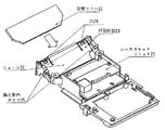
図1は本発明の実施形態に係るバーコード読取装置の構成を示す分解斜視図であり、反射ミラーはシャーシから取り外されている状態で示されている。
【0015】
図1においてバーコード読取装置は、大きく3つに分けられて示されている。すなわち、図1においては取付けの順番が分かるように、合成樹脂例えばABS樹脂から成る上ケース10と、反射ミラー22が分離された状態で図示されているが組立時には取付けられ更にレーザスキャナユニット21が搭載された、合成樹脂例えばPC(ポリカーボネイト)から成るシャーシ20と、合成樹脂例えばABS樹脂から成る下ケース30とから構成されている。
【0016】
そして、バーコード読取装置を組み立てる場合には、先ず図1において分離されている反射ミラー22をシャーシ20に取付けた後に、このシャーシ20を上ケース10に取付け、さらにその上に下ケース30を取付けて締結用ねじにより締結して、バーコード読取装置を組み立てる。
【0017】
図2は、図1で示したシャーシ20の構成を示すものであり、このシャーシ20に反射ミラー22を固定する様子を示す斜視図である。図3は、反射ミラー22をシャーシ20に固定した後の様子を示す斜視図である。
【0018】
図2においてシャーシには、図1においても説明したようにレーザスキャナユニット21が搭載されており、さらに反射ミラー22が矢印方向から挿入されて固定される。すなわち、反射ミラー22の固定に関与する部材としては、傾斜したシャーシ20の両側部に形成される爪取付け部23に設けられた爪24と、傾斜したシャーシ20の両側部に形成される挿入案内ガイド25と、図2及び図3には示されていないが、傾斜したシャーシ20の底部に形成される反射ミラー22を受け止める突き当て(ストッパ)(図4参照)が用意されているものである。
【0019】
上述したようにシャーシは合成樹脂から成るために弾性力を有しており、さらに図2からも分かるように爪取付け部23はシャーシ20に切り込みがなされて構成されているので爪24に弾性力がさらに付加される構成となっており、反射ミラー22を爪24で抑えて固定する際には弾性的に固定することができる(図5も参照されたい)。
【0020】
反射ミラー22をシャーシ20に取付・固定するための作業としては、まず反射ミラー22を図2の矢印方向から挿入案内ガイド25に案内されながら挿入して、反射ミラー22が傾斜したシャーシ20の底部に形成された反射ミラー22を受け止める突き当て(ストッパ)(図5の参照番号26を参照)に突き当たるまで挿入する。すると、上記した爪取付け部23に設けられた弾性力のある爪24に反射ミラー22の上端が係合して固定される(図5も参照)。
【0021】
なお、反射ミラーやシャーシなどの寸法及びその較差については特に図示してはいないが、寸法としてはシャーシ20に反射ミラー22を挿入して固定できるように設定されると共にその較差に対しても十分に配慮しているけれども、シャーシ20は上記したように合成樹脂例えばPCから成るためシャーシ20には弾性特性が付与されていおり、それぞれ較差があったとしても反射ミラー22を緩みなく取付・固定することができる。
【0022】
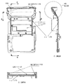
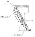
図4は、図3に示した反射ミラーを取付けたシャーシの平面図と、縦方向においてA−A方向から見たA−A断面図と、横方向においてB−B方向から見たB−B断面図を示している。また図5は図4のA−A断面図のうち反射ミラーの固定部分を拡大した部分拡大図である。
【0023】
図4のB−B断面図において反射ミラー22はシャーシ20の背面と挿入案内ガイド25に挟まれて背面方向及び左右方向が固定されるのが分かる。
【0024】
また図5の拡大断面図において反射ミラー22はシャーシの底部に設けた突き当て(ストッパ)26と爪24とによって反射ミラーの上下方向が固定されるのが分かる。
【0025】
【発明の効果】
以上説明したように本発明は、レーザ光源から放射されたレーザ光を反射ミラーで反射させてバーコードを読み取るバーコード読取装置において、前記反射ミラーを取付ける傾斜するシャーシの弾性部分に爪を設け、この爪に前記反射ミラーの上端を係合させて前記反射ミラーを保持するようにし、前記爪は、前記傾斜するシャーシの爪取付部の上端に設け、前記爪取付部である傾斜するシャーシにばね性を持たせたバーコード読取装置であって、前記傾斜するシャーシの側面に挿入案内ガイドを設け、この挿入案内ガイドに前記反射ミラーをスロットインで挿入し固定することを特徴とするものであり、この構成を採ることにより、側面における位置決めを行って反射ミラーをシャーシに容易に取付け保持することができるので、バーコード読取装置の組立を容易化することができる。
【0026】
また、振動、衝撃によりミラーが移動して読み取り誤りが生じることを防止することができる。
【図面の簡単な説明】
【図1】本発明の実施形態に係るバーコード読取装置の構成を示す分解斜視図、
【図2】図1で示したシャーシ20の構成を示すもので、シャーシ20に反射ミラー22を固定する様子を示す斜視図、
【図3】図2において反射ミラー22をシャーシ20に固定した後の様子を示す斜視図、
【図4】図3に示した反射ミラーを取付けたシャーシの平面図と、縦方向においてA−A方向から見たA−A断面図と、横方向においてB−B方向から見たB−B断面図、
【図5】図4のA−A断面図のうち反射ミラーの固定部分を拡大した部分拡大図である。
【符号の説明】
10 上ケース
20 シャーシ
21 レーザスキャナユニット
22 反射ミラー
23 爪取付部
24 爪
25 挿入案内ガイド
26 突き当て(ストッパ)
30 下ケース[0001]
[Technical field to which the invention belongs]
The present invention relates to a bar code reader that reads a bar code by reflecting laser light emitted from a laser light source with a reflection mirror, and more particularly to a bar code reader that devise a structure for holding a reflection mirror that reflects laser light. This facilitates assembly and prevents rattling.
[0002]
[Prior art]
In the assembly of a conventional bar code reader, when a reflecting mirror that reflects laser light is fixed to the chassis, the reflecting mirror is simply fixed to the chassis by adhesive tape or screwing a mirror holding member.
[0003]
[Problems to be solved by the invention]
Such a conventional method of fixing the reflecting mirror has a problem that it is difficult to obtain the accuracy of the mounting, and the mounting is costly. In addition, when it is simply fixed to the chassis with an adhesive tape or the like, there has been a problem that the attachment position changes due to secular change, vibration or impact, and the barcode reader becomes defective.
[0004]
The present invention has been made in order to solve such problems, and provides a barcode reader that facilitates assembly by devising a structure for holding a reflecting mirror that reflects laser light. It is for the purpose.
[0005]
[Means for Solving the Problems]
According to a first aspect of the present invention, in a bar code reader for reading a bar code by reflecting a laser beam emitted from a laser light source with a reflecting mirror, a claw is provided on an inclined chassis to which the reflecting mirror is attached. The upper end of the reflection mirror is engaged to hold the reflection mirror, and the claw is provided at the upper end of the claw mounting portion of the inclined chassis, and the inclined chassis that is the claw mounting portion has a spring property. The barcode reader is provided with an insertion guide guide on a side surface of the inclined chassis, and the reflection mirror is inserted into the insertion guide guide by slot-in and fixed .
[0006]
In this way, the slanting chassis, which is the claw mounting part, has a spring property, so that the reflecting mirror can be easily mounted and held on the slanting chassis, and the claw provided on the top of the slanting chassis can The reflection mirror can be prevented from being detached from the chassis to be mounted, and the positioning on the side surface can be performed, so that the reflection mirror can be easily attached .
[0007]
The invention according to claim 2 of the present application is the barcode reader according to claim 1, wherein the lower end of the inclined chassis is provided with an abutment of a reflecting mirror, and the lower end of the reflecting mirror is pressed against the abutment. The reflection mirror is held.
[0008]
Thus, since the reflecting mirror is abutted against the abutting provided at the lower end of the inclined chassis, the reflecting mirror can be prevented from being detached from the inclined chassis.
[0011]
The invention according to claim 3 of the present application is the barcode reader according to claim 1 , wherein the insertion guide guide is provided with a floating prevention portion for preventing the reflection mirror from floating to prevent the reflection mirror from floating. It is what.
[0012]
By adopting this configuration, it is possible to prevent floating when the reflecting mirror is attached.
[0013]
DETAILED DESCRIPTION OF THE INVENTION
Hereinafter, embodiments of the present invention will be described with reference to FIGS.
[0014]
FIG. 1 is an exploded perspective view showing a configuration of a bar code reader according to an embodiment of the present invention, in which a reflection mirror is removed from a chassis.
[0015]
In FIG. 1, the bar code reader is roughly divided into three parts. That is, in FIG. 1, the upper case 10 made of a synthetic resin, for example, ABS resin, and the reflection mirror 22 are shown in a separated state so that the mounting order can be seen. A chassis 20 made of synthetic resin such as PC (polycarbonate) and a lower case 30 made of synthetic resin such as ABS resin are mounted.
[0016]
When assembling the bar code reader, first, the reflecting mirror 22 separated in FIG. 1 is attached to the chassis 20, then the chassis 20 is attached to the upper case 10, and further the lower case 30 is attached thereon. The bar code reader is assembled by fastening with fastening screws.
[0017]
FIG. 2 shows the configuration of the chassis 20 shown in FIG. 1 and is a perspective view showing how the reflection mirror 22 is fixed to the chassis 20. FIG. 3 is a perspective view showing a state after the reflection mirror 22 is fixed to the chassis 20.
[0018]
In FIG. 2, the laser scanner unit 21 is mounted on the chassis as described in FIG. 1, and the reflection mirror 22 is inserted and fixed from the direction of the arrow. That is, the members involved in fixing the reflecting mirror 22 include the
[0019]
As described above, since the chassis is made of synthetic resin, it has elastic force. Further, as can be seen from FIG. 2, the claw mounting portion 23 is formed by cutting the chassis 20 so that the
[0020]
As an operation for mounting and fixing the reflection mirror 22 to the chassis 20, first, the reflection mirror 22 is inserted while being guided by the insertion guide guide 25 from the direction of the arrow in FIG. The reflecting mirror 22 formed on the surface is inserted until it abuts against the abutment (stopper) (see reference numeral 26 in FIG. 5). Then, the upper end of the reflecting mirror 22 is engaged with and fixed to the
[0021]
Although the dimensions of the reflection mirror and the chassis and the range thereof are not specifically shown, the dimensions are set so that the reflection mirror 22 can be inserted and fixed to the chassis 20 and the range is sufficient. However, since the chassis 20 is made of a synthetic resin such as PC as described above, the chassis 20 is given elastic properties, and even if there is a difference, the reflection mirror 22 is attached and fixed without looseness. be able to.
[0022]
4 is a plan view of the chassis to which the reflecting mirror shown in FIG. 3 is attached, a cross-sectional view taken along the line AA in the vertical direction, and a cross-sectional view taken along the line BB in the horizontal direction. A cross-sectional view is shown. FIG. 5 is a partially enlarged view in which the fixed portion of the reflecting mirror is enlarged in the AA sectional view of FIG.
[0023]
4 that the reflecting mirror 22 is sandwiched between the back surface of the chassis 20 and the insertion guide guide 25, and the back surface direction and the left-right direction are fixed.
[0024]
In addition, in the enlarged sectional view of FIG. 5, it can be seen that the reflecting mirror 22 is fixed in the vertical direction of the reflecting mirror by an abutment (stopper) 26 and a
[0025]
【The invention's effect】
As described above, the present invention provides a claw on the elastic portion of the inclined chassis to which the reflection mirror is attached in the barcode reader that reads the barcode by reflecting the laser light emitted from the laser light source by the reflection mirror, The upper end of the reflection mirror is engaged with the claw so as to hold the reflection mirror, and the claw is provided at the upper end of the claw mounting portion of the inclined chassis, and the spring is applied to the inclined chassis that is the claw mounting portion. The bar code reader is provided with an insertion guide provided on a side surface of the inclined chassis, and the reflection mirror is inserted into the insertion guide guide by slot-in and fixed . by adopting this configuration, it is possible to easily mount holding the reflecting mirror to the chassis by performing positioning of the side surface, bar code It is possible to facilitate the assembly of the reading device.
[0026]
Further, it is possible to prevent the reading error due to the movement of the mirror due to vibration and impact.
[Brief description of the drawings]
FIG. 1 is an exploded perspective view showing a configuration of a bar code reader according to an embodiment of the present invention;
FIG. 2 is a perspective view showing a configuration of the chassis 20 shown in FIG. 1 and showing a state in which a reflection mirror 22 is fixed to the chassis 20;
3 is a perspective view showing a state after the reflection mirror 22 is fixed to the chassis 20 in FIG.
4 is a plan view of a chassis to which the reflecting mirror shown in FIG. 3 is attached, a cross-sectional view taken along the line AA in the vertical direction, and a cross-sectional view taken along the line BB in the horizontal direction. Sectional view,
5 is a partially enlarged view in which a fixed portion of the reflecting mirror is enlarged in the AA cross-sectional view of FIG. 4;
[Explanation of symbols]
10 Upper case
20 Chassis
21 Laser scanner unit
22 Reflection mirror
23 Claw mounting part
24 nails
25 Insertion guide
26 Butting (stopper)
30 Lower case
Claims (3)
前記傾斜するシャーシの側面に挿入案内ガイドを設け、この挿入案内ガイドに前記反射ミラーをスロットインで挿入し固定することを特徴とするバーコード読取装置。In a barcode reader for reading a barcode by reflecting a laser beam emitted from a laser light source with a reflection mirror, a claw is provided on an inclined chassis to which the reflection mirror is attached, and an upper end of the reflection mirror is engaged with the claw. The bar code reader is configured to hold the reflecting mirror, and the claw is provided at an upper end of the claw mounting portion of the inclined chassis, and the inclined chassis which is the claw mounting portion has a spring property. ,
An bar code reader , wherein an insertion guide guide is provided on a side surface of the inclined chassis, and the reflection mirror is inserted into the insertion guide guide in a slot-in manner and fixed .
Priority Applications (1)
| Application Number | Priority Date | Filing Date | Title |
|---|---|---|---|
| JP28966499A JP4222696B2 (en) | 1999-10-12 | 1999-10-12 | Bar code reader |
Applications Claiming Priority (1)
| Application Number | Priority Date | Filing Date | Title |
|---|---|---|---|
| JP28966499A JP4222696B2 (en) | 1999-10-12 | 1999-10-12 | Bar code reader |
Publications (2)
| Publication Number | Publication Date |
|---|---|
| JP2001109837A JP2001109837A (en) | 2001-04-20 |
| JP4222696B2 true JP4222696B2 (en) | 2009-02-12 |
Family
ID=17746164
Family Applications (1)
| Application Number | Title | Priority Date | Filing Date |
|---|---|---|---|
| JP28966499A Expired - Fee Related JP4222696B2 (en) | 1999-10-12 | 1999-10-12 | Bar code reader |
Country Status (1)
| Country | Link |
|---|---|
| JP (1) | JP4222696B2 (en) |
-
1999
- 1999-10-12 JP JP28966499A patent/JP4222696B2/en not_active Expired - Fee Related
Also Published As
| Publication number | Publication date |
|---|---|
| JP2001109837A (en) | 2001-04-20 |
Similar Documents
| Publication | Publication Date | Title |
|---|---|---|
| WO2018092473A1 (en) | Mounting structure for in-vehicle electronic device | |
| CN111712405B (en) | Sensor assembly structure for rotary-mounted windshield-mounted vehicle interior mirror | |
| US8654406B2 (en) | Image reading apparatus with a transparent member biased by a positioning member | |
| JPH11112161A (en) | Lock mechanism, device housing structure, device fixing mechanism, and glass fixing mechanism | |
| JP4222696B2 (en) | Bar code reader | |
| JP5063809B2 (en) | Assembly structure for panel | |
| US7782736B2 (en) | Optical pickup for a disk apparatus | |
| US6764188B2 (en) | Light scanner | |
| US6556528B1 (en) | Fixing device for data storage device of computer | |
| US6744723B2 (en) | Guide shaft support mechanism and recording medium recording and reproducing apparatus | |
| CN100508037C (en) | Mounting structure for mounting the laser bracket on the base member | |
| JP3991973B2 (en) | Disc player | |
| JP3529047B2 (en) | Optical pickup | |
| JP4096320B2 (en) | Disc loader mounting structure | |
| JP4470046B2 (en) | Optical pickup | |
| JP3054198U (en) | Member engagement structure and optical pickup device | |
| JP4081757B2 (en) | Attachment mounting structure | |
| JP4105984B2 (en) | Optical pickup device | |
| JP2592713Y2 (en) | Reflection mirror mounting mechanism | |
| JP2012155811A (en) | Sheet metal component fitting structure for optical pickup | |
| JP4141965B2 (en) | Box-shaped housing structure | |
| JP3229553B2 (en) | Optical path changing device for bar code reader | |
| JP3052886U (en) | Optical pickup device | |
| KR100357919B1 (en) | Optical pickup and mrthod for assembling the same | |
| JPH0621014U (en) | Collimator |
Legal Events
| Date | Code | Title | Description |
|---|---|---|---|
| A621 | Written request for application examination |
Free format text: JAPANESE INTERMEDIATE CODE: A621 Effective date: 20060908 |
|
| A131 | Notification of reasons for refusal |
Free format text: JAPANESE INTERMEDIATE CODE: A131 Effective date: 20080722 |
|
| A521 | Request for written amendment filed |
Free format text: JAPANESE INTERMEDIATE CODE: A523 Effective date: 20080917 |
|
| TRDD | Decision of grant or rejection written | ||
| A01 | Written decision to grant a patent or to grant a registration (utility model) |
Free format text: JAPANESE INTERMEDIATE CODE: A01 Effective date: 20081021 |
|
| A01 | Written decision to grant a patent or to grant a registration (utility model) |
Free format text: JAPANESE INTERMEDIATE CODE: A01 |
|
| A61 | First payment of annual fees (during grant procedure) |
Free format text: JAPANESE INTERMEDIATE CODE: A61 Effective date: 20081118 |
|
| R150 | Certificate of patent or registration of utility model |
Free format text: JAPANESE INTERMEDIATE CODE: R150 |
|
| FPAY | Renewal fee payment (event date is renewal date of database) |
Free format text: PAYMENT UNTIL: 20111128 Year of fee payment: 3 |
|
| LAPS | Cancellation because of no payment of annual fees |