JP4222610B2 - Liquid-gas contact device - Google Patents
Liquid-gas contact device Download PDFInfo
- Publication number
- JP4222610B2 JP4222610B2 JP2003516649A JP2003516649A JP4222610B2 JP 4222610 B2 JP4222610 B2 JP 4222610B2 JP 2003516649 A JP2003516649 A JP 2003516649A JP 2003516649 A JP2003516649 A JP 2003516649A JP 4222610 B2 JP4222610 B2 JP 4222610B2
- Authority
- JP
- Japan
- Prior art keywords
- liquid
- gas
- honeycomb structure
- gas contact
- contact device
- Prior art date
- Legal status (The legal status is an assumption and is not a legal conclusion. Google has not performed a legal analysis and makes no representation as to the accuracy of the status listed.)
- Expired - Fee Related
Links
Images


Landscapes
- Air Humidification (AREA)
- Vaporization, Distillation, Condensation, Sublimation, And Cold Traps (AREA)
Description
技術分野
本発明は、冷却装置、抽出装置及び調湿装置等として使用可能な液−ガス接触装置に関する。
背景技術
現在人類の日常生活そのものに起因する環境への影響が各方面で問題化しつつある。そのような問題の一つに、ゴミの焼却に伴う環境汚染物質の発生がある。
例えば、都市ごみ焼却炉から排出される排ガス中には、煤塵、塩化水素(HCl)、SOX、NOX、水銀を含む重金属類やダイオキシン等の微量成分が含まれており、環境保全の立場から、これらの有害物質の除去が必要である。なかでも、ダイオキシン類(PCDD:ポリ塩化ジベンゾジオキシン及びPCDF:ポリ塩化ジベンゾフランの総称)については、極めて毒性が強く、しかも発ガン性をも有することが報告されており、ダイオキシン類の捕集・除去は緊急課題として取り上げられている。
しかしながら、焼却炉からの排ガス処理をした場合、所望の低濃度までダイオキシン類を削減することができないケースが生じている。
すなわち、ごみの焼却過程で生成したダイオキシン類は、2次燃焼室でほぼ分解されるが、排ガス処理工程である熱回収工程、冷却反応工程及び集塵工程の各工程において、焼却炉排ガスは約350〜900℃程度の高温から集塵に適した低温へ温度を下げる必要がある。この際、ダイオキシンのデノボ再合成温度領域(約300℃近傍)を短時間で急冷通過させることが、ダイオキシンの再合成防止の観点から必要である。
ダイオキシンのデボノ再合成温度領域(300℃)を急冷しつつ、150℃以下の低温まで下げることは、従来の熱交換器型のガス冷却では装置が大型となり、効率が悪かった。
このため、気化潜熱を利用した水噴霧による冷却が行われているが、大きな容積が必要であるため、装置の設備も大型となり、運転コストもかかるという問題点があった。
ところで、いわゆるハニカム構造体は、多数のセルが並列する複数のセル列を形成した構造体であり、軽量高強度の構造材(航空機用等)、通気量が大きい触媒担体(自動車排ガス浄化用等)等の他、微小な細孔を有するセラミック多孔質体を基材とした場合には、単位面積当たりの濾過面積が大きい集塵フィルタ、固液分離フィルタとしても利用されており、更に冷却装置、抽出装置及び調湿装置などへの適用が検討されている。しかし、これらの装置としての具体的な提案は実用性の点で、未だ完全なものと言えないの現状である。
本発明は、このような従来技術の有する課題に鑑みてなされたものであり、その目的とするところは、ハニカム構造体の外周面側から液体を毛細管現象により複数の隔壁に浸透させ、ガスと液体との接触時に生じる気化潜熱を用いることにより、熱効率に優れているとともに、シンプル且つコンパクトにすることができる液−ガス接触装置を提供することにある。
発明の開示
本発明は、気体供給部と液体供給部とを備えた、液−ガス接触装置において、気体−液体接触媒体として多孔質材からなるハニカム構造体を使用したことを特徴とする液−ガス接触装置に関する。
また、本発明は、上記の液−ガス接触装置の利用方法に関する。第一に、複数の隔壁により規定される、構造体の軸方向に貫通する複数の流通孔が形成された多孔質材からなり、更に、ハニカム構造体の外周面側から貫通し、且つ該流通孔と隔絶されて形成された複数の流路を有するハニカム構造体である液−ガス接触媒体、ガスの取り入れ口、ガスの取り出し口、液体供給口、液体用貯槽、所望により有していてもよい液体排出口が設けられた、同液−ガス接触媒体を収納する容器からなる液−ガス接触装置を用い、前記液−ガス接触媒体の複数の隔壁により規定されて形成された該ハニカム構造体の軸方向に貫通する複数の流通孔に気体(ガス体を含む)を、該ハニカム構造体の外周面側から貫通し、且つ該流通孔と隔絶されて形成された流路に液体を流通させ、毛細管現象で液体を該流通孔側の隔壁に浸透させることにより、ガスと液体とを接触させ、毛細管現象により液体を該流通孔側の隔壁に浸透させることにより、ガスと液体とを接触させ、ガスと液体との接触時に生じる気化潜熱でガスを冷却することによる冷却装置としての利用、即ち、ガス冷却方法に関する。
第二に、複数の隔壁により規定される、構造体の軸方向に貫通する複数の流通孔が形成された多孔質材からなり、更に、ハニカム構造体の外周面側から貫通し、且つ該流通孔と隔絶されて形成された複数の流路を有するハニカム構造体である液−ガス接触媒体、ガスの取り入れ口、ガスの取り出し口、液体供給口、液体用貯槽、所望により有していてもよい液体排出口が設けられた、同液−ガス接触媒体を収納する容器からなる液−ガス接触装置を用い、前記液−ガス接触媒体の複数の隔壁により規定されて形成された該ハニカム構造体の軸方向に貫通する複数の流通孔に気体(ガス体を含む)を、該ハニカム構造体の外周面側から貫通し、且つ該流通孔と隔絶されて形成された流路に液体を流通させ、毛細管現象で液体を該流通孔側の隔壁に浸透させることにより、ガスと液体とを接触させ、毛細管現象により液体を該流通孔側の隔壁に浸透させることにより、ガスと液体とを接触させ、ガスと溶液との接触時に生じる気化潜熱で溶媒を蒸発させることにより、流路内の溶液を濃縮することによる抽出装置としての利用、即ち、溶液の濃縮方法に関する。
第三に、複数の隔壁により規定される、構造体の軸方向に貫通する複数の流通孔が形成された多孔質材からなり、更に、ハニカム構造体の外周面側から貫通し、且つ該流通孔と隔絶されて形成された複数の流路を有するハニカム構造体である液−ガス接触媒体、ガスの取り入れ口、ガスの取り出し口、液体供給口、液体用貯槽、所望により有していてもよい液体排出口が設けられた、同液−ガス接触媒体を収納する容器からなる液−ガス接触装置を用い、前記液−ガス接触媒体の複数の隔壁により規定されて形成された該ハニカム構造体の軸方向に貫通する複数の流通孔に気体、例えば、空気を、該ハニカム構造体の外周面側から貫通し、且つ該流通孔と隔絶されて形成された流路に液体、例えば、上水を流通させ、毛細管現象で上水を該流通孔側の隔壁に浸透させることにより、空気と上水とを接触させ、毛細管現象により上水を該流通孔側の隔壁に浸透させることにより、空気と上水とを接触させ、空気と上水との接触時に生じる気化潜熱で上水を蒸発させ、空気に水蒸気を含ませることによる調湿装置としての利用、即ち、加湿方法に関する。
発明を実施するための最良の形態
本発明の液−ガス接触装置は、液−ガス接触媒体、ガスの取り入れ口、ガスの取り出し口、液体供給口、液体用貯槽、所望により有していてもよい液体排出口が設けられた、同液−ガス接触媒体を収納する容器からなる。
かくして、本発明によれば、液−ガス接触媒体であるハニカム構造体の外周面側から液体が毛細管現象により複数の隔壁に浸透し、ガスと液体との接触時に生じる気化潜熱を用いて、所望とする作用を発揮させることにより、熱効率に優れた、シンプルで、且つ、コンパクトな液−ガス接触装置が提供される。
本発明における液−ガス接触媒体は、複数の隔壁により規定された、構造体の軸方向に貫通する複数の流通孔が形成された多孔質材から構成される液−ガス接触媒体である。そして、この接触媒体は、同ハニカム構造体の外周面側から液体を複数の隔壁に浸透させると共に、流通孔にガスを流通させ、前記隔壁の近傍において液体とガスとを接触させることにより、所望とする作用を発揮するものである。
液−ガス接触媒体を収納する容器としては、用途に応じた強度が担保させる限り、その材質は問わないが、通常は、金属製や樹脂製のものが好適に使用される。容器には、ガスの取り入れ口、およびガスの取り出し口が設けられる。容器としては、円筒状等の中空のものを使用する場合には、いずれか一方の開口部をガスの取り入れ口とし、他方の開口部をガスの取り出し口として使用してもよい。
液体供給口、液体用貯槽、所望により有していてもよい液体排出口は、装置の用途などに応じて、適切な箇所に設ければよく、その限りにおいて、特別な制限はない。
なお、本発明における液−ガス接触媒体は、セラミック製なので、容器に収納するに際しては、緩衝材を使用することが好ましい。かかる緩衝材としては、セラミックス繊維等が好適に使用される。
本発明の液−ガス接触媒体における流路12とは、その利用目的に応じて、液体をガスと液−ガス接触媒体において接触させることができる機能を有するものであれば、特にその形状、構造などは問わない。通常、液−ガス接触媒体として、具備すべき形状、大きさ、配置位置等の詳述については、後述することとするが、例えば、複数の隔壁により規定されハニカム構造体の軸方向に貫通して存在する複数の流通孔を有する、ハニカム構造体10の流通孔開口部から外周部に貫通するように、特定に間隔で特定の深さまで孔部を穿設した後、上記流路12の開放端部を封止部材で、ハニカム構造体10の少なくとも一方の末端から所定の厚さまで目封じすることにより、形成される。
以下、本発明の実施の形態を図面に基づいて詳細に説明する。
本発明の液−ガス接触装置においては、液−ガス接触媒体10としては、例えば、図1(a)および(b)並びに図2(a)および(b)に示すように、多孔質材からなるハニカム構造体10であって、複数の隔壁により規定された、同構造体の軸方向に貫通して形成された複数の流通孔(セル)14と、同ハニカム構造体10の外周面側から貫通し、且つ、流通孔14とは隔絶されて形成された流路12を有するものである。
これらの図に示した本発明の液−ガス接触装置においては、流通孔(セル)14にガス40を、流路12に液体30を流通させることにより、ガス40と液体30とを隔壁近傍において接触させ、毛細管現象で液体30を流通孔12側の隔壁に浸透させ、ガス40と液体30との接触による液体の気化を利用するものである。
ここで、本発明の液−ガス接触装置の主な特徴は、ハニカム構造体を用いることにより、ガスとの接触面積を大きくすることができるとともに、ハニカム構造体が微細な細孔径を有する多孔質材から形成されているため、毛細管現象を利用し、液体の蒸発を非常に高効率で行うことができる点にある。
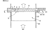
例えば、図1(a)および(b)並びに図2(a)および(b)に示す液−ガス接触装置は、流路12が配設されたハニカム構造体10と、上記ハニカム構造体10を収容することにより、ガス流路を形成するとともに、流路12に液体30を供給する貯槽22が付設された金属製容器20と、貯槽22に液体30を供給する液体供給管24から構成される。此処で肝要なことは、液体が流路12内へ効率良く流れ込むことを可能にするために、ガス流の流れ方向において、流路12の高さが、液体用貯槽22に蓄えられる液体30の高さを充分にカバーするような位置に流路12のいずれか少なくとも何れか一方の端部を位置するように設けることである。
上記のような液−ガス接触装置は、ガスと液体との接触時に生じる気化潜熱で、液体の蒸発を非常に高効率で行うことができるため、ガスを冷却する冷却装置やガスに液体蒸気を付与する調湿装置として好適に用いることができる。また、効率良く可燃性液体を気化し、可燃混合気を生成する気化器としても好適に用いることができる。
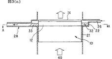
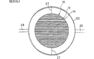
また、図3(a)および(b)に示す液−ガス接触装置は、流路12が配設されたハニカム構造体10と、上記ハニカム構造体10を収容することにより、ガス流路を形成するとともに、流路12に溶液32を供給する貯槽22が付設されたメタルケース20と、貯槽22に溶液32を供給する溶液供給管26と、濃縮溶液33を貯槽22から回収する溶液回収管28からなるものである。
上記のような液−ガス接触装置は、ガス40と溶液32との接触時に生じる気化潜熱により溶液32中の溶媒の蒸発を非常に高効率で行うことができるため、溶液32を濃縮する抽出装置として食品産業、化学工業などの各分野で好適に用いることができる。
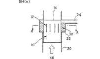
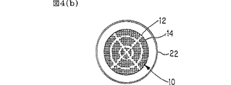
尚、上記ハニカム構造体10のセル開口面における流路12の配置形状としては、図1(a)および(b)、図2(a)および(b)、並びに図3(a)および(b)に示した配置形状に限定されず、図4(b)に示す同心円状と十字状と組み合わせた形としてもよく、図5(b)に示す側面に開口する位置が交互に配置された千鳥状、図6(b)に示す井桁状のものを適宜、選択または組み合わせた配置形状としてもよい。
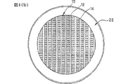
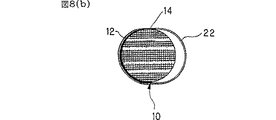
図8(a)および(b)は、流路を液体の浸透方向に形成させた例であって、これらの図に示すように、効率良く流路12内へ流体が供給されやすくするためにハニカム構造体10に液体を供給する液体用貯槽22の形状に合わせて、セル開口面における流路12の形状・配置を最適化することが好ましい。
また、上記液−ガス接触媒体として使用するハニカム構造体10に設けられる流路12の位置、特に図1(a)および図2(a)においてcで示されるセル開口面からの距離、断面形状、図1(a)および図2(a)に示された形状、断面積、即ち、図1(a)および図2(a)における流路の幅a×流路の長さbで与えられる面積、及び各流路間の間隔、即ち、図1(a)および図2(a)におけるdは、液−ガス接触媒体として使用されるハニカム構造体の材質、気孔率及び平均細孔径により定まることは勿論のこと、液−ガス接触装置の用途との関係、特にその蒸発性能等を考慮して、適宜決定することが好ましい。
従って、液−ガス接触装置の用途や使用するハニカム構造体により、隔壁内部に存在する微細な孔部が充分流路として機能する場合には、図7(a)および(b)に示すように、特別に独立した流路が設けられていないハニカム構造体10でも用いることもできる。勿論、使用目的、操作条件等に左右されることなく機能を発揮させる点から見れば、独立した複数の流路を有することが、好ましい。
本発明において液−ガス接触媒体として使用するハニカム構造体の場合、その形状、サイズ、セル形状、セル孔径、セル間隔(セル壁厚さ)等は、液−ガス接触装置の用途との関係で、最適のものを選択すればよく、その条件を満たす限り特に制限を受けるものではない。
なお、各流路12の間の間隔dとしては、ハニカム構造体の容積1l当たりのガス流量Q(Nm3/min)との関係で、以下の条件を満足させるものであることが好ましい:
(d)< 20×(α/Q)[mm]。
例えば、本発明において液−ガス接触媒体として使用するハニカム構造体の断面形状は、円形(図1(a)(b)〜図8(a)(b)参照)、正方形(図9(a)(b)参照)、長方形、或いは六角形等の筒状体とすることができ、各セルの形状についても、円形、三角形、四角形、五角形、六角形をはじめとする種々の形状を用いることができる。
通常、本発明において液−ガス接触媒体として使用するハニカム構造体としては、リブ(隔壁)厚が1.5〜32mil(0.0375〜0.8mm)、セル密度が10〜1200cpsi(約1.6セル〜186セル/cm2)のものから、用途などを考慮して適宜選択すればよい。
また、本発明において液−ガス接触媒体として使用するハニカム構造体は、気孔率が10〜70%であり、且つ平均細孔径が5〜100μmであるものから、用途などを考慮して適宜選択すればよい。
更に、本発明において液−ガス接触媒体として使用するハニカム構造体の材質は、多孔質材であれば、特に限定されないが、例えば、コージェライト、アルミナ、ムライト、SiC、窒化珪素からなる群より選ばれた少なくとも1種の多孔質材であることが好ましく、用途などを考慮して選択することが好ましい。
以下、本発明を実施例に基づいて更に詳細に説明するが、本発明はこれらの実施例に限定されるものではない。
実施例1
(液−ガス接触装置:燃焼排ガスの冷却)
気孔率35%、平均細孔径10μmであり、リブ厚80μm、セル密度62セル/cm2のセル構造を有するコージェライト製のハニカム構造体(直径118mm、長さ60mm)に、幅1.3mm(1セル分)(a)、高さ15mm(b)で、その断面形状が軸方向に縦長の長方形である流路12を、上記ハニカム構造体10の流通孔開口部から外周部に貫通するように、5mmの間隔(d)で13本穿設した後、上記流路12の開放端部を封止部材で、ハニカム構造体10の末端から10mmの厚さ(c)で目封じした[図1(a)および(b)参照]。
上記ハニカム構造体10を、図1(a)および(b)に示すように、シールを兼ねたマット21を介して円筒状の金属製容器20内に収容し、金属製容器20に付設された貯槽22から水30を流路12への流通を開始させた後、プロパンガスの燃焼排ガス(ガス温度500℃)を金属製容器20の下側のガス供給口から同容器の上側にあるガス排出口に向けて0.7Nm3/minの流量で流し、水供給管24からは、水30を180cc/minの流量で供給した。その結果を図10に示す。
実施例2〜3
(液−ガス接触装置:燃焼排ガスの冷却)
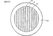
気孔率35%、平均細孔径10μmであり、リブ厚80μm、セル密度62セル/cm2のセル構造を有するコージェライト製のハニカム構造体(直径118mm、長さ60mm)に、幅3.8mm(3セル分)(a)、高さ15mm(b)で、その断面形状が軸方向に縦長の長方形である流路12を、上記ハニカム構造体10の流通孔開口部から外周部に貫通するように、4.6mmの間隔(d)で11本穿設した後、上記流路12の開放端部を封止部材で、ハニカム構造体10の末端から10mmの厚さ(c)で目封じした[図2(a)および(b)参照]。
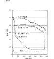
上記ハニカム構造体10を、図2(a)および(b)に示すように、シールを兼ねたマット21を介して円筒状の金属製容器20内に収容し、金属製容器20に付設された貯槽22から水30を流路12への流通を開始させた後、プロパンガスの燃焼排ガス(ガス温度500℃)を金属製容器20の下側のガス供給口から同容器の上側にあるガス排出口に向けて0.7Nm3/minの流量で流し、水供給管24から水30を、180cc/min(実施例2)の流量で供給した。その結果を図11に示す。
また、上記ハニカム構造体10を、図2(a)および(b)に示すように、シールを兼ねたマット21を介して円筒状の金属製容器20内に収容し、金属製容器20に付設された貯槽22から水30を流路12への流通を開始させせた後、プロパンガスの燃焼排ガス(ガス温度500℃)を金属製容器20の下側のガス供給口から同容器の上側にあるガス排出口に向けて0.7Nm3/minの流量で流し、水供給管24から水30を、260cc/minの流量で供給した(実施例3)。
考察:実施例1〜3
実施例1では、図10に示すように、燃焼ガス温度が定常になった時点(180sec)で、出口ガス温度が200℃であり、ガス温度を300℃低減させることができた。
また、実施例2では、実施例1よりも流路容積を大きくすることにより、図11に示すように、燃焼排ガスの温度が定常になった時点(180sec)で、出口ガス温度が130℃であり、燃焼排ガスの温度を370℃低減させることができた。
更に、実施例3では、実施例2と同じ条件で、水供給量を260cc/minに増やすことにより、燃焼排ガスの温度が定常になった時点(180sec)で、出口ガス温度が70℃であり、燃焼排ガスの温度を430℃低減させることができた。
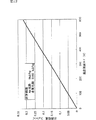
このとき、水供給量(kg/min)と温度低減ΔT(K)との関係は、図12に示すように、比例していることを確認した。
(実施例4:液−ガス接触装置で用いるハニカム構造体の流路の最適化)
同一のセル構造(12mil[約0.3mm],200cpsi)でφ20mm×50mmのハニカム構造体を標準サンプル形状とし、φ30mmのシャーレ深さ5mmの水を3.5cc用意し、ハニカムサンプルをその中に立てた際、水を吸い取るのにかかる時間で吸水性を評価した。
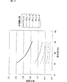
気孔率30%、平均細孔径10μmのコージェライトをベースとして、吸水指数αを算出した。吸水指数αと気孔率との関係を図13に示す。
この吸水指数αに応じて、異なる材料を用いる際には、図1(a)および(b)、図2(a)および(b)、図3(a)および(b)、図4(a)および(b)、図5(a)および(b)、図6(a)および(b)、図7(a)および(b)、図6(a)および(b)、並びに図9(a)および(b)に示すハニカム構造体10の流路12の間隔dを下式のように適宜調節することが、液−ガス接触装置としての性能を発揮させるために、必要であることを見出した。
ハニカム構造体の容積1l当たりのガス流量Q(Nm3/min)に対し、
(流路の間隔d)< 20×(α/Q)[mm]
産業上の利用可能性
本発明の液−ガス接触装置は、冷却装置、溶液濃縮装置、抽出装置、調湿装置及び可燃液体気化器に好適に使用することができる。
特に、本発明の液−ガス接触装置は、ハニカム構造体の外周面側から液体を毛細管現象により複数の隔壁に浸透させ、ガスと液体との接触機会を大幅に増加させられるため、熱効率に優れているとともに、シンプル且つコンパクトにすることができる。
また、冷却装置として用いる場合には、シンプル且つコンパクトな構造で液体の気化潜熱を利用できるため、設置性、経済性に優れたものとなる。
【図面の簡単な説明】
図1(a)および(b)は、本発明の液−ガス接触装置の一例を示すものであり、図1(a)は概略断面図、図1(b)は図1(a)のA−A断面図である。
図2(a)および(b)は、本発明の液−ガス接触装置の他の例を示すものであり、図2(a)は概略断面図、図2(b)は図2(a)のA−A断面図である。
図3(a)および(b)は、本発明の液−ガス接触装置の更に他の例を示すものであり、図3(a)は概略断面図、図3(b)は図3(a)のA−A断面図である。
図4(a)および(b)は、本発明の液−ガス接触装置の別の例▲1▼を示すものであり、図4(a)は概略断面図、図4(b)は図4(a)のA−A断面図である。
図5(a)および(b)は、本発明の液−ガス接触装置の別の例▲2▼を示すものであり、図5(a)は概略断面図、図5(b)は図5(a)のA−A断面図である。
図6(a)および(b)は、本発明の液−ガス接触装置の別の例▲3▼を示すものであり、図6(a)は概略断面図、図6(b)は図6(a)のA−A断面図である。
図7(a)および(b)は、本発明の液−ガス接触装置の別の例▲4▼を示すものであり、図7(a)は概略断面図、図7(b)は図7(a)のA−A断面図である。
図8(a)および(b)は、本発明の液−ガス接触装置の別の例▲5▼を示すものであり、図8(a)は概略断面図、図8(b)は図8(a)のA−A断面図である。
図9(a)および(b)は、本発明の液−ガス接触装置の別の例▲6▼を示すものであり、図9(a)は概略断面図、図9(b)は図9(a)のA−A断面図である。
図10は、実施例1における水供給経過時間に対する燃焼排ガスの温度の関係を示すグラフである。
図11は、実施例2における水供給経過時間に対する燃焼排ガスの温度の関係を示すグラフである。
図12は、実施例における水供給量(kg/min)と温度低減ΔT(K)との関係を示すグラフである。
図13は、ハニカム構造体の平均細孔径における吸水性(吸水指数)と気孔率との関係を示すグラフである。TECHNICAL FIELD The present invention relates to a liquid-gas contact device that can be used as a cooling device, an extraction device, a humidity control device, and the like.
Background Art Currently, the impact on the environment caused by the daily lives of humankind is becoming a problem in various fields. One such problem is the generation of environmental pollutants associated with incineration of garbage.
For example, exhaust gas discharged from municipal waste incinerators contains trace components such as dust, hydrogen chloride (HCl), SO X , NO X , heavy metals including mercury, and dioxin. Therefore, it is necessary to remove these harmful substances. In particular, dioxins (PCDD: polychlorinated dibenzodioxin and PCDF: polychlorinated dibenzofuran) are reported to be extremely toxic and carcinogenic, and collect and remove dioxins. Has been taken up as an urgent issue.
However, when exhaust gas treatment from an incinerator is performed, there are cases where dioxins cannot be reduced to a desired low concentration.
That is, the dioxins generated in the incineration process of the waste are almost decomposed in the secondary combustion chamber. In each process of the heat recovery process, the cooling reaction process and the dust collection process, which is an exhaust gas treatment process, the incinerator exhaust gas is about It is necessary to lower the temperature from a high temperature of about 350 to 900 ° C. to a low temperature suitable for dust collection. At this time, it is necessary to rapidly cool the deoxin recombination temperature region (around 300 ° C.) of dioxin in a short time from the viewpoint of preventing dioxin resynthesis.
To rapidly cool the debono resynthesis temperature range (300 ° C.) of dioxin to a low temperature of 150 ° C. or less, the conventional heat exchanger type gas cooling is large in size and inefficient.
For this reason, although cooling by water spray using vaporization latent heat is performed, since a large volume is required, there is a problem that the equipment of the apparatus becomes large and the operation cost increases.
By the way, a so-called honeycomb structure is a structure in which a plurality of cell rows in which a large number of cells are arranged in parallel, and is a lightweight and high-strength structural material (for aircraft, etc.), a catalyst carrier having a large air flow rate (for automobile exhaust gas purification, etc.) In addition to the above, when a ceramic porous body having fine pores is used as a base material, it is also used as a dust collection filter and a solid-liquid separation filter having a large filtration area per unit area. Application to extraction devices and humidity control devices has been studied. However, specific proposals for these devices are not yet perfect in terms of practicality.
The present invention has been made in view of such problems of the prior art, and the object of the present invention is to infiltrate a liquid into a plurality of partition walls by capillary action from the outer peripheral surface side of the honeycomb structure, An object of the present invention is to provide a liquid-gas contact device that is excellent in thermal efficiency and can be made simple and compact by using latent heat of vaporization generated at the time of contact with a liquid.
DISCLOSURE OF THE INVENTION The present invention provides a liquid-gas contact device including a gas supply unit and a liquid supply unit, wherein a honeycomb structure made of a porous material is used as a gas-liquid contact medium. The present invention relates to a gas contact device.
Moreover, this invention relates to the utilization method of said liquid-gas contact apparatus. First, it is made of a porous material in which a plurality of flow holes penetrating in the axial direction of the structure are defined by a plurality of partition walls. Liquid-gas contact medium that is a honeycomb structure having a plurality of flow paths isolated from the pores, a gas inlet, a gas outlet, a liquid supply port, a liquid storage tank, even if desired The honeycomb structure formed by using a liquid-gas contact device comprising a container containing the same liquid-gas contact medium provided with a good liquid discharge port and defined by a plurality of partition walls of the liquid-gas contact medium A gas (including a gas body) is passed through a plurality of flow holes penetrating in the axial direction of the honeycomb structure from the outer peripheral surface side of the honeycomb structure, and liquid is circulated through a flow path formed to be isolated from the flow holes. The partition wall on the side of the flow hole by the liquid by capillary action The gas and liquid are brought into contact with each other, and the liquid is brought into contact with the partition wall on the flow hole side by capillarity to bring the gas and liquid into contact with each other. The present invention relates to use as a cooling device by cooling the gas, that is, a gas cooling method.
Secondly, it is made of a porous material in which a plurality of through holes penetrating in the axial direction of the structure body, defined by a plurality of partition walls, is formed, and further penetrates from the outer peripheral surface side of the honeycomb structure body, and Liquid-gas contact medium that is a honeycomb structure having a plurality of flow paths isolated from the pores, a gas inlet, a gas outlet, a liquid supply port, a liquid storage tank, even if desired The honeycomb structure formed by using a liquid-gas contact device comprising a container containing the same liquid-gas contact medium provided with a good liquid discharge port and defined by a plurality of partition walls of the liquid-gas contact medium A gas (including a gas body) is passed through a plurality of flow holes penetrating in the axial direction of the honeycomb structure from the outer peripheral surface side of the honeycomb structure, and liquid is circulated through a flow path formed to be isolated from the flow holes. The partition wall on the side of the flow hole by the liquid by capillary action The gas and liquid are brought into contact with each other, and the liquid is brought into contact with the partition wall on the flow hole side by capillarity to bring the gas and liquid into contact with each other. The present invention relates to use as an extraction device by concentrating the solution in the flow path by evaporating the solution, that is, a method for concentrating the solution.
Third, the porous material is formed of a porous material in which a plurality of flow holes penetrating in the axial direction of the structure body, which are defined by the plurality of partition walls, is formed, and further penetrates from the outer peripheral surface side of the honeycomb structure body. Liquid-gas contact medium that is a honeycomb structure having a plurality of flow paths isolated from the pores, a gas inlet, a gas outlet, a liquid supply port, a liquid storage tank, even if desired The honeycomb structure formed by using a liquid-gas contact device comprising a container containing the same liquid-gas contact medium provided with a good liquid discharge port and defined by a plurality of partition walls of the liquid-gas contact medium A gas such as air is passed through the plurality of flow holes penetrating in the axial direction of the honeycomb structure from the outer peripheral surface side of the honeycomb structure and is separated from the flow holes. Circulate and supply clean water by capillary action. Air and clean water are brought into contact with each other by infiltrating the partition wall on the hole side, and air and clean water are brought into contact with each other by allowing water to penetrate into the partition wall on the flow hole side by capillary action. The present invention relates to utilization as a humidity control device by evaporating clean water with latent heat of vaporization generated upon contact with water and including water vapor in the air, that is, a humidification method.
BEST MODE FOR CARRYING OUT THE INVENTION The liquid-gas contact device of the present invention has a liquid-gas contact medium, a gas inlet, a gas outlet, a liquid supply port, a liquid storage tank, if desired. It consists of a container for storing the same liquid-gas contact medium provided with a good liquid discharge port.
Thus, according to the present invention, the liquid permeates into the plurality of partition walls by the capillary phenomenon from the outer peripheral surface side of the honeycomb structure which is the liquid-gas contact medium, and the desired vaporization latent heat generated at the time of contact between the gas and the liquid is used. The simple and compact liquid-gas contact apparatus excellent in thermal efficiency is provided by exhibiting the effect of.
The liquid-gas contact medium in the present invention is a liquid-gas contact medium composed of a porous material in which a plurality of flow holes penetrating in the axial direction of the structure are defined by a plurality of partition walls. Then, the contact medium allows a liquid to permeate into the plurality of partition walls from the outer peripheral surface side of the honeycomb structure, and allows a gas to flow through the flow holes, thereby bringing the liquid and the gas into contact with each other in the vicinity of the partition walls. It demonstrates the effect of.
The container for storing the liquid-gas contact medium is not particularly limited as long as the strength according to the application is ensured, but usually a metal or resin container is preferably used. The container is provided with a gas inlet and a gas outlet. When a hollow container such as a cylindrical shape is used, either one of the openings may be used as a gas inlet, and the other opening may be used as a gas outlet.
The liquid supply port, the liquid storage tank, and the liquid discharge port that may be optionally provided may be provided at an appropriate location according to the use of the apparatus, and as long as there is no particular limitation.
In addition, since the liquid-gas contact medium in this invention is a product made from a ceramic, when accommodating in a container, it is preferable to use a buffer material. As such a buffer material, ceramic fiber or the like is preferably used.
The
Hereinafter, embodiments of the present invention will be described in detail with reference to the drawings.
In the liquid-gas contact device of the present invention, as the liquid-
In the liquid-gas contact device of the present invention shown in these drawings, the
Here, the main features of the liquid-gas contact device of the present invention are that the honeycomb structure can be used to increase the contact area with the gas, and the honeycomb structure has a porous structure with a fine pore diameter. Since it is formed from a material, it is possible to use a capillary phenomenon to evaporate a liquid with very high efficiency.
For example, the liquid-gas contact device shown in FIGS. 1 (a) and 1 (b) and FIGS. 2 (a) and 2 (b) includes a
The liquid-gas contact device as described above is a latent heat of vaporization generated when the gas and the liquid come into contact with each other, and can evaporate the liquid with very high efficiency. It can use suitably as a humidity control apparatus to provide. Moreover, it can use suitably also as a vaporizer which vaporizes a combustible liquid efficiently and produces | generates a combustible mixture.
Further, the liquid-gas contact device shown in FIGS. 3A and 3B forms a gas flow path by accommodating the
Since the liquid-gas contact device as described above can evaporate the solvent in the
In addition, as the arrangement | positioning shape of the
FIGS. 8A and 8B are examples in which the flow path is formed in the liquid permeation direction, and in order to facilitate the efficient supply of fluid into the
Further, the position of the
Therefore, depending on the use of the liquid-gas contact device and the honeycomb structure to be used, when fine holes existing inside the partition walls sufficiently function as flow paths, as shown in FIGS. It is also possible to use the
In the case of a honeycomb structure used as a liquid-gas contact medium in the present invention, the shape, size, cell shape, cell hole diameter, cell interval (cell wall thickness), etc. are related to the use of the liquid-gas contact device. What is necessary is just to select an optimal thing, and it will not receive a restriction | limiting especially if the conditions are satisfy | filled.
The distance d between the
(D) <20 × (α / Q) [mm].
For example, the cross-sectional shape of the honeycomb structure used as the liquid-gas contact medium in the present invention is circular (see FIGS. 1 (a) (b) to 8 (a) (b)), square (FIG. 9 (a)). (Refer to (b)), it can be a cylinder such as a rectangle or a hexagon, and the shape of each cell can be a variety of shapes including a circle, a triangle, a rectangle, a pentagon, and a hexagon. it can.
In general, the honeycomb structure used as the liquid-gas contact medium in the present invention has a rib (partition) thickness of 1.5 to 32 mil (0.0375 to 0.8 mm) and a cell density of 10 to 1200 cpsi (about 1. 6 cells to 186 cells / cm 2 ) may be selected as appropriate in consideration of applications.
In addition, the honeycomb structure used as the liquid-gas contact medium in the present invention has a porosity of 10 to 70% and an average pore diameter of 5 to 100 μm. That's fine.
Furthermore, the material of the honeycomb structure used as the liquid-gas contact medium in the present invention is not particularly limited as long as it is a porous material. For example, it is selected from the group consisting of cordierite, alumina, mullite, SiC, and silicon nitride. It is preferable that the material is at least one kind of porous material selected, and it is preferable to select it in consideration of the application.
EXAMPLES Hereinafter, although this invention is demonstrated further in detail based on an Example, this invention is not limited to these Examples.
Example 1
(Liquid-gas contact device: cooling of combustion exhaust gas)
A cordierite honeycomb structure (diameter 118 mm,
As shown in FIGS. 1A and 1B, the
Examples 2-3
(Liquid-gas contact device: cooling of combustion exhaust gas)
A cordierite honeycomb structure (diameter 118 mm,
2 (a) and 2 (b), the
2A and 2B, the
Discussion: Examples 1-3
In Example 1, as shown in FIG. 10, when the combustion gas temperature became steady (180 sec), the outlet gas temperature was 200 ° C., and the gas temperature could be reduced by 300 ° C.
Further, in Example 2, the outlet gas temperature is 130 ° C. when the temperature of the combustion exhaust gas becomes steady (180 sec) as shown in FIG. Yes, the temperature of the combustion exhaust gas could be reduced by 370 ° C.
Furthermore, in Example 3, the outlet gas temperature is 70 ° C. when the temperature of the combustion exhaust gas becomes steady (180 sec) by increasing the water supply amount to 260 cc / min under the same conditions as in Example 2. The temperature of the combustion exhaust gas could be reduced by 430 ° C.
At this time, it was confirmed that the relationship between the water supply amount (kg / min) and the temperature reduction ΔT (K) was proportional as shown in FIG.
(Example 4: Optimization of the flow path of the honeycomb structure used in the liquid-gas contact device)
A honeycomb structure with the same cell structure (12 mil [about 0.3 mm], 200 cpsi) and a φ20 mm × 50 mm honeycomb structure is prepared as a standard sample shape, and 3.5 cc of water with a φ30 mm petri dish depth of 5 mm is prepared. When standing, water absorption was evaluated by the time taken to absorb water.
The water absorption index α was calculated based on cordierite having a porosity of 30% and an average pore diameter of 10 μm. The relationship between the water absorption index α and the porosity is shown in FIG.
When different materials are used according to the water absorption index α, FIGS. 1A and 1B, FIGS. 2A and 2B, FIGS. 3A and 3B, and FIG. ) And (b), FIG. 5 (a) and (b), FIG. 6 (a) and (b), FIG. 7 (a) and (b), FIG. 6 (a) and (b), and FIG. It is necessary to appropriately adjust the distance d between the
For the gas flow rate Q (Nm 3 / min) per 1 liter of honeycomb structure,
(Distance between flow paths d) <20 × (α / Q) [mm]
Industrial Applicability The liquid-gas contact device of the present invention can be suitably used for a cooling device, a solution concentration device, an extraction device, a humidity control device, and a combustible liquid vaporizer.
In particular, the liquid-gas contact device of the present invention is excellent in thermal efficiency because liquid can permeate into a plurality of partition walls by capillary action from the outer peripheral surface side of the honeycomb structure, and the contact opportunity between gas and liquid can be greatly increased. And simple and compact.
Moreover, when using as a cooling device, since the vaporization latent heat of a liquid can be utilized with a simple and compact structure, it will be excellent in installation property and economical efficiency.
[Brief description of the drawings]
1 (a) and 1 (b) show an example of the liquid-gas contact device of the present invention. FIG. 1 (a) is a schematic cross-sectional view, and FIG. 1 (b) is A in FIG. 1 (a). It is -A sectional drawing.
2 (a) and 2 (b) show another example of the liquid-gas contact device of the present invention. FIG. 2 (a) is a schematic sectional view, and FIG. 2 (b) is FIG. 2 (a). It is AA sectional drawing.
3 (a) and 3 (b) show still another example of the liquid-gas contact device of the present invention. FIG. 3 (a) is a schematic cross-sectional view, and FIG. 3 (b) is FIG. It is AA sectional drawing of).
4 (a) and 4 (b) show another example (1) of the liquid-gas contact device of the present invention, FIG. 4 (a) is a schematic sectional view, and FIG. 4 (b) is FIG. It is AA sectional drawing of (a).
5 (a) and 5 (b) show another example (2) of the liquid-gas contact device of the present invention, FIG. 5 (a) is a schematic sectional view, and FIG. 5 (b) is FIG. It is AA sectional drawing of (a).
6 (a) and 6 (b) show another example (3) of the liquid-gas contact device of the present invention, FIG. 6 (a) is a schematic sectional view, and FIG. 6 (b) is FIG. It is AA sectional drawing of (a).
7 (a) and 7 (b) show another example (4) of the liquid-gas contact device of the present invention. FIG. 7 (a) is a schematic sectional view, and FIG. 7 (b) is FIG. It is AA sectional drawing of (a).
8 (a) and 8 (b) show another example (5) of the liquid-gas contact device of the present invention, FIG. 8 (a) is a schematic sectional view, and FIG. 8 (b) is FIG. It is AA sectional drawing of (a).
9 (a) and 9 (b) show another example (6) of the liquid-gas contact device of the present invention, FIG. 9 (a) is a schematic sectional view, and FIG. 9 (b) is FIG. It is AA sectional drawing of (a).
FIG. 10 is a graph showing the relationship of the temperature of the combustion exhaust gas with respect to the water supply elapsed time in Example 1.
FIG. 11 is a graph showing the relationship of the temperature of the combustion exhaust gas with respect to the water supply elapsed time in Example 2.
FIG. 12 is a graph showing the relationship between the water supply amount (kg / min) and the temperature reduction ΔT (K) in the example.
FIG. 13 is a graph showing the relationship between the water absorption (water absorption index) and the porosity at the average pore diameter of the honeycomb structure.
Claims (5)
該液−ガス接触媒体を収納し、その端部には、ガスの取り入れ口とガスの取り出し口とを規定する壁を有する収納容器であって、
該収納容器は、液体供給口を備えるとともに、ハニカム構造体の外周壁の一部により構成されている側壁を備えた液体用貯槽とを有し、該収納容器は、該ハニカム構造体を、上記液体用貯槽に貯蔵されて用いられる液体が、該ハニカム構造体の軸方向における上端面よりも低い位置で、かつ、同構造体の上部側に隣接する位置に位置するように、保持しており、そして、該収納容器は、液体用貯槽よりも下部で、ハニカム構造体の外周壁とは密封されているものからなる、
液−ガス接触装置であって、
該液体用貯槽中の溶液を、毛管現象によりハニカム構造体をガス流路へと通り抜けさせて、溶液を、同流路を流れているガスと接触させることを特徴とする液−ガス接触装置。A plurality of gas passages formed of a porous material, defined by a plurality of partition walls, penetrating in the axial direction of the structure and open at both ends, and an outer peripheral portion of the shaft. A liquid-gas contact medium comprising a honeycomb structure having an outer peripheral wall formed extending from one to the other;
A storage container containing the liquid-gas contact medium, and having walls defining gas inlets and gas outlets at its ends ;
The container is provided with a liquid supply port, have a liquid for storage tank having a side wall which is constituted by a part of the outer peripheral wall of the honeycomb structure, the receiving container, the honeycomb structure, the The liquid stored and used in the liquid storage tank is held at a position lower than the upper end surface in the axial direction of the honeycomb structure and at a position adjacent to the upper side of the structure. and 該収 paid container at lower than for liquid storage tank, consisting of those which are sealed to the outer peripheral wall of the honeycomb structure,
A liquid-gas contact device comprising:
A liquid-gas contact device characterized in that the solution in the liquid storage tank is caused to pass through the honeycomb structure to the gas flow path by capillary action, and the solution is brought into contact with the gas flowing through the flow path.
Applications Claiming Priority (5)
| Application Number | Priority Date | Filing Date | Title |
|---|---|---|---|
| JPPCT/JP01/06522 | 2001-07-30 | ||
| JP2003516677 | 2001-07-30 | ||
| JP2003516677 | 2001-07-30 | ||
| PCT/JP2001/006522 WO2003011452A1 (en) | 2001-07-30 | 2001-07-30 | Liquid-gas contact apparatus |
| PCT/JP2002/007667 WO2003011419A1 (en) | 2001-07-30 | 2002-07-29 | Liquid-to-gas contact device |
Publications (3)
| Publication Number | Publication Date |
|---|---|
| JPWO2003011419A1 JPWO2003011419A1 (en) | 2004-11-18 |
| JP4222610B2 true JP4222610B2 (en) | 2009-02-12 |
| JP4222610B6 JP4222610B6 (en) | 2009-04-30 |
Family
ID=
Also Published As
| Publication number | Publication date |
|---|---|
| JPWO2003011419A1 (en) | 2004-11-18 |
Similar Documents
| Publication | Publication Date | Title |
|---|---|---|
| KR100675501B1 (en) | An air filter assembly for low temperature catalytic processes and a system for producing power comprising the same | |
| US7569089B2 (en) | Boundary layer propulsion and turbine apparatus | |
| JP2007105683A (en) | Gas recovery method and apparatus | |
| JPH02500962A (en) | filter device | |
| JP2002517307A (en) | Micro component assembly for effective fluid contact | |
| US6626983B1 (en) | Method and apparatus for removing particulates | |
| US7281703B2 (en) | Liquid-to-gas contact device | |
| US8016917B2 (en) | Method and apparatus for pollution control of confined spaces | |
| JP4222610B2 (en) | Liquid-gas contact device | |
| JP4222610B6 (en) | Liquid-gas contact device | |
| JP2001276546A (en) | Dust removing device | |
| EP1645322B1 (en) | Apparatus for removing nitrogen oxides | |
| JP3706627B1 (en) | Exhaust gas treatment facility with integrated filter dust collector | |
| JP3759154B1 (en) | Exhaust gas denitration device, integrated filtration dust collector equipped with the device, and exhaust gas treatment facility | |
| EP4403840A1 (en) | A liquid-washing air purifying and disinfecting device | |
| CN207654949U (en) | One kind being based on UV photodissociation catalytic oxidation systems | |
| JP2001185188A (en) | Tank for fluid containing carbon and hydrogen | |
| JP2005296859A (en) | Harmful substance decomposition method and harmful substance decomposition apparatus | |
| JP2005125206A (en) | High concentration malodor and volatile organic compound recovery treatment equipment | |
| JP2005140012A (en) | Exhaust emission control device | |
| JP2005230678A (en) | Exhaust gas treatment apparatus and exhaust gas treatment method | |
| RU83431U1 (en) | ADJUSTABLE EXHAUST FILTER FOR REMOVING VOLATILE COMPOUNDS FROM GAS AIR EMISSIONS | |
| Kennes et al. | Non-biological treatment technologies | |
| JPS6039063Y2 (en) | Harmful gas removal equipment | |
| JP2001259334A (en) | Device for removing soot, dust and the like |
Legal Events
| Date | Code | Title | Description |
|---|---|---|---|
| A131 | Notification of reasons for refusal |
Free format text: JAPANESE INTERMEDIATE CODE: A131 Effective date: 20071211 |
|
| A521 | Request for written amendment filed |
Free format text: JAPANESE INTERMEDIATE CODE: A523 Effective date: 20080131 |
|
| A131 | Notification of reasons for refusal |
Free format text: JAPANESE INTERMEDIATE CODE: A131 Effective date: 20080603 |
|
| A521 | Request for written amendment filed |
Free format text: JAPANESE INTERMEDIATE CODE: A523 Effective date: 20080729 |
|
| TRDD | Decision of grant or rejection written | ||
| A01 | Written decision to grant a patent or to grant a registration (utility model) |
Free format text: JAPANESE INTERMEDIATE CODE: A01 Effective date: 20081111 |
|
| A01 | Written decision to grant a patent or to grant a registration (utility model) |
Free format text: JAPANESE INTERMEDIATE CODE: A01 |
|
| A61 | First payment of annual fees (during grant procedure) |
Free format text: JAPANESE INTERMEDIATE CODE: A61 Effective date: 20081117 |
|
| R150 | Certificate of patent or registration of utility model |
Ref document number: 4222610 Country of ref document: JP Free format text: JAPANESE INTERMEDIATE CODE: R150 Free format text: JAPANESE INTERMEDIATE CODE: R150 |
|
| FPAY | Renewal fee payment (event date is renewal date of database) |
Free format text: PAYMENT UNTIL: 20111128 Year of fee payment: 3 |
|
| FPAY | Renewal fee payment (event date is renewal date of database) |
Free format text: PAYMENT UNTIL: 20111128 Year of fee payment: 3 |
|
| FPAY | Renewal fee payment (event date is renewal date of database) |
Free format text: PAYMENT UNTIL: 20111128 Year of fee payment: 3 |
|
| FPAY | Renewal fee payment (event date is renewal date of database) |
Free format text: PAYMENT UNTIL: 20121128 Year of fee payment: 4 |
|
| FPAY | Renewal fee payment (event date is renewal date of database) |
Free format text: PAYMENT UNTIL: 20131128 Year of fee payment: 5 |
|
| LAPS | Cancellation because of no payment of annual fees |