JP4221473B2 - Game machine - Google Patents
Game machine Download PDFInfo
- Publication number
- JP4221473B2 JP4221473B2 JP2007137259A JP2007137259A JP4221473B2 JP 4221473 B2 JP4221473 B2 JP 4221473B2 JP 2007137259 A JP2007137259 A JP 2007137259A JP 2007137259 A JP2007137259 A JP 2007137259A JP 4221473 B2 JP4221473 B2 JP 4221473B2
- Authority
- JP
- Japan
- Prior art keywords
- command
- payout
- game
- ball
- control
- Prior art date
- Legal status (The legal status is an assumption and is not a legal conclusion. Google has not performed a legal analysis and makes no representation as to the accuracy of the status listed.)
- Expired - Fee Related
Links
Images


Description
本発明は、遊技者が遊技媒体を用いて遊技を行うパチンコ遊技機やスロット機等の遊技機に関する。 The present invention relates to a gaming machine such as a pachinko gaming machine or a slot machine in which a player plays a game using a gaming medium.
遊技機として、遊技球などの遊技媒体を発射装置によって遊技領域に発射し、遊技領域に設けられている入賞口などの入賞領域に遊技媒体が入賞すると、所定個の遊技媒体が賞球として遊技者に払い出されるものがある。さらに、表示状態が変化可能な可変表示装置が設けられ、可変表示装置における表示結果があらかじめ定められた特定の表示態様となった場合に所定の遊技価値を遊技者に与えるように構成されたものがある。 As a gaming machine, a game medium such as a game ball is launched into a game area by a launching device, and when a game medium wins a prize area such as a prize opening provided in the game area, a predetermined number of game media are played as prize balls. Is paid out to the person. Further, a variable display device capable of changing the display state is provided, and is configured to give a predetermined game value to a player when a display result on the variable display device becomes a predetermined specific display mode There is.
特別図柄を表示する可変表示装置における表示結果があらかじめ定められた特定の表示態様の組合せとなることを、通常、「大当り」という。なお、遊技価値とは、遊技機の遊技領域に設けられた可変入賞球装置の状態が打球が入賞しやすい遊技者にとって有利な状態になることや、遊技者にとって有利な状態となるための権利を発生させたりすることである。 That the display result in the variable display device that displays the special symbol is a combination of specific display modes determined in advance is usually referred to as “big hit”. Note that the game value is the right that the state of the variable winning ball device provided in the gaming area of the gaming machine is advantageous for a player who is likely to win a ball, or the advantageous state for a player. It is to generate.
大当りが発生すると、例えば、大入賞口が所定回数開放して打球が入賞しやすい大当り遊技状態に移行する。そして、各開放期間において、所定個(例えば10個)の大入賞口への入賞があると大入賞口は閉成する。そして、大入賞口の開放回数は、所定回数(例えば16ラウンド)に固定されている。なお、各開放について開放時間(例えば29.5秒)が決められ、入賞数が所定個に達しなくても開放時間が経過すると大入賞口は閉成する。また、大入賞口が閉成した時点で所定の条件(例えば、大入賞口内に設けられているVゾーンへの入賞)が成立していない場合には、大当り遊技状態は終了する。 When the big hit occurs, for example, the big winning opening is opened a predetermined number of times, and the game shifts to a big hit gaming state where the hit ball is easy to win. And in each open period, if there is a prize for a predetermined number (for example, 10) of the big prize opening, the big prize opening is closed. And the number of times the special winning opening is opened is fixed to a predetermined number (for example, 16 rounds). An opening time (for example, 29.5 seconds) is determined for each opening, and even if the number of winnings does not reach a predetermined number, the big winning opening is closed when the opening time elapses. Further, when a predetermined condition (for example, winning in the V zone provided in the big prize opening) is not established at the time when the big prize opening is closed, the big hit gaming state is ended.
遊技機における遊技進行はマイクロコンピュータ等による遊技制御手段によって制御される。そして、可変表示装置に表示される識別情報は、遊技制御手段の遊技制御マイクロコンピュータとは別の表示制御用のマイクロコンピュータを含む表示制御手段によって制御される。さらに、遊技機において、スピーカ等の音発生手段が設けられ、遊技効果を増進するために遊技の進行に伴ってスピーカから種々の効果音や音声が発せられる。また、遊技盤や枠側にランプやLED等の発光体が設けられ、遊技効果を増進するために遊技の進行に伴ってそれらの発光体が点灯されたり消灯されたりする。そして、音発生手段や発光体を制御するために、音制御手段を搭載した音制御基板を遊技制御手段とは別に設けたり、発光体制御手段を搭載した発光体制御基板を遊技制御手段とは別に設けた構成が採用されることがある。 The game progress in the gaming machine is controlled by game control means such as a microcomputer. The identification information displayed on the variable display device is controlled by display control means including a display control microcomputer different from the game control microcomputer of the game control means. Furthermore, in the gaming machine, sound generating means such as a speaker is provided, and various sound effects and sounds are emitted from the speaker as the game progresses in order to enhance the gaming effect. In addition, light emitters such as lamps and LEDs are provided on the game board and the frame side, and these light emitters are turned on and off as the game progresses in order to enhance the game effect. And in order to control the sound generating means and the light emitter, a sound control board equipped with a sound control means is provided separately from the game control means, or a light emitter control board equipped with the light emitter control means is a game control means. A separately provided configuration may be employed.
賞球払出の制御を行う払出制御手段が、遊技制御手段が搭載されている遊技制御基板とは別の払出制御基板に搭載されている場合、遊技の進行は遊技制御基板に搭載された遊技制御手段によって制御されるので、入賞にもとづく賞球個数は、遊技制御手段によって決定され、払出制御基板に送信される。一方、遊技媒体の貸し出しは、遊技の進行とは無関係であるから、一般に、遊技制御手段を介さず払出制御手段によって制御される。 When the payout control means for controlling the prize ball payout is mounted on a payout control board different from the game control board on which the game control means is mounted, the progress of the game is controlled by the game control mounted on the game control board. Since it is controlled by the means, the number of winning balls based on the winning is determined by the game control means and transmitted to the payout control board. On the other hand, the rental of game media is irrelevant to the progress of the game, and is generally controlled by the payout control means without going through the game control means.
以上のように、遊技機には、遊技制御手段の他に種々の制御手段が搭載されている。そして、遊技の進行を制御する遊技制御手段は、遊技状況に応じて動作指示を示す各コマンドを、各制御基板に搭載された各制御手段に送信する。以下、遊技機に設けられている制御手段を電気部品制御手段といい、電気部品制御手段が搭載された基板を電気部品制御基板ということがある。 As described above, various control means are mounted on the gaming machine in addition to the game control means. Then, the game control means for controlling the progress of the game transmits each command indicating an operation instruction according to the game situation to each control means mounted on each control board. Hereinafter, the control means provided in the gaming machine may be referred to as electrical component control means, and the board on which the electrical component control means is mounted may be referred to as an electrical component control board.
上記のような遊技機において、遊技機に対する電力供給を開始する場合に、遊技店員がRAMクリア等の遊技機の初期化作業を容易に行えるようにすることが望ましい。In the gaming machine as described above, it is desirable that the game shop clerk can easily perform initialization work of the gaming machine such as RAM clearing when the power supply to the gaming machine is started.
そこで、本発明は、クリアスイッチをオン状態にしながら遊技機に対する電力供給を開始することによって、容易に初期化処理を実行させることができる遊技機を提供することを目的とする。 Accordingly, an object of the present invention is to provide a gaming machine that can easily execute an initialization process by starting power supply to the gaming machine while turning on a clear switch .
本発明による遊技機は、遊技者が所定の遊技を行うことが可能な遊技機であって、制御を行う際に発生する変動データを記憶する遊技制御用変動データ記憶手段を有し、遊技の進行を制御する遊技制御用マイクロコンピュータと、遊技機への電力供給が停止していても遊技制御用変動データ記憶手段の記憶内容を所定期間保持させることが可能な記憶内容保持手段と、遊技媒体を検出するための遊技媒体検出手段に供給される電圧よりも高い所定電源電圧の電圧低下を検出して、電源断の発生を検出したときに検出信号を出力する電源監視手段と、操作に応じて操作信号を出力する初期化操作手段とを備え、遊技制御用マイクロコンピュータは、検出信号の入力に応じて、遊技制御用変動データ記憶手段の記憶内容が正常か否かの判定に用いるチェックデータの作成処理を含む遊技制御用電力供給停止時処理を実行し、電力供給が開始されたときに、初期化操作手段から操作信号が入力されているか否かを判定し、初期化操作手段からの操作信号が入力されていれば、チェックデータにもとづく遊技制御用変動データ記憶手段の記憶内容が正常か否かの判定を行うことなく、遊技制御用変動データ記憶手段の記憶内容を初期化し、初期化操作手段から操作信号が入力されていないと判定されたときに、チェックデータにもとづいて遊技制御用変動データ記憶手段の記憶内容が正常か否かの判定を実行し、遊技制御用変動データ記憶手段の記憶内容が正常であると判定されたことを条件に、遊技制御用変動データ記憶手段に保存されていた記憶内容にもとづいて制御状態を遊技制御用電力供給停止時処理を開始したときの状態に復旧させる遊技制御用状態復帰制御を実行し、初期化操作手段からの操作信号が入力されているか否かを、遊技媒体検出手段から出力される信号が有効と判定される遊技媒体検出判定期間よりも短い要求検出判定期間で判定することを特徴とする。
また、本発明による遊技機の他の態様は、遊技者が所定の遊技を行うことが可能な遊技機であって、制御を行う際に発生する変動データを記憶する払出制御用変動データ記憶手段を有し、遊技媒体の払出の制御を行う払出制御用マイクロコンピュータと、遊技機への電力供給が停止していても払出制御用変動データ記憶手段の記憶内容を所定期間保持させることが可能な記憶内容保持手段と、遊技媒体を検出するための遊技媒体検出手段に供給される電圧よりも高い所定電源電圧の電圧低下を検出して、電源断の発生を検出したときに検出信号を出力する電源監視手段と、操作に応じて操作信号を出力する初期化操作手段とを備え、払出制御用マイクロコンピュータは、検出信号の入力に応じて、払出制御用変動データ記憶手段の記憶内容が正常か否かの判定に用いるチェックデータの作成処理を含む払出制御用電力供給停止時処理を実行し、電力供給が開始されたときに、初期化操作手段から操作信号が入力されているか否かを判定し、初期化操作手段からの操作信号が入力されていれば、チェックデータにもとづく払出制御用変動データ記憶手段の記憶内容が正常か否かの判定を行うことなく、払出制御用変動データ記憶手段の記憶内容を初期化し、初期化操作手段から操作信号が入力されていないと判定されたときに、チェックデータにもとづいて払出制御用変動データ記憶手段の記憶内容が正常か否かの判定を実行し、払出制御用変動データ記憶手段の記憶内容が正常であると判定されたことを条件に、払出制御用変動データ記憶手段に保存されていた記憶内容にもとづいて制御状態を払出制御用電力供給停止時処理を開始したときの状態に復旧させる払出制御用状態復帰制御を実行し、初期化操作手段からの操作信号が入力されているか否かを、遊技媒体検出手段から出力される信号が有効と判定される遊技媒体検出判定期間よりも短い要求検出判定期間で判定することを特徴とする。
A gaming machine according to the present invention is a gaming machine in which a player can play a predetermined game, and has a game control variation data storage means for storing variation data generated when control is performed . A game control microcomputer for controlling the progress, a storage content holding means capable of holding the storage contents of the game control variation data storage means for a predetermined period even when power supply to the gaming machine is stopped, and a game medium A power supply monitoring means for detecting a voltage drop of a predetermined power supply voltage higher than the voltage supplied to the game medium detecting means for detecting the power supply, and outputting a detection signal when the occurrence of power interruption is detected, and depending on the operation The game control microcomputer is used to determine whether or not the stored content of the game control variation data storage means is normal according to the input of the detection signal. A process for stopping power supply for game control including a process for creating check data is executed, and when power supply is started, it is determined whether or not an operation signal is input from the initialization operation means, and the initialization operation means If the operation signal is input, the memory content of the game control variation data storage means is initialized without determining whether the memory content of the game control variation data storage means is normal based on the check data. When it is determined that the operation signal is not input from the initialization operation means, it is determined whether or not the stored content of the game control variation data storage means is normal based on the check data, and the game control variation On the condition that the stored contents of the data storage means are normal, the control state is set for game control based on the stored contents stored in the variation data storage means for game control. A signal output from the game medium detection means for executing whether or not an operation signal from the initialization operation means is input, executing a state return control for game control to restore the state at the time of starting the power supply stop process Is determined in a request detection determination period shorter than the game medium detection determination period in which it is determined to be valid .
Further, another aspect of the gaming machine according to the present invention is a gaming machine in which a player can play a predetermined game, and a variation data storage means for payout control that stores variation data generated when control is performed. And the storage contents of the payout control variation data storage means can be held for a predetermined period even when the power supply to the gaming machine is stopped. A voltage drop of a predetermined power supply voltage higher than the voltage supplied to the stored content holding means and the game medium detection means for detecting a game medium is detected, and a detection signal is output when the occurrence of power interruption is detected. Power supply monitoring means and initialization operation means for outputting an operation signal in response to an operation, and the payout control microcomputer stores the contents of the payout control variation data storage means in response to the input of the detection signal. Whether or not an operation signal is input from the initialization operation means when the power supply stop process for payout control including the process of creating check data used to determine whether or not it is normal is executed and the power supply is started If the operation signal from the initialization operation means is input, the payout control variation data is determined without determining whether the storage content of the payout control variation data storage means based on the check data is normal or not. Initializing the storage contents of the storage means and determining whether or not the storage contents of the payout control variation data storage means are normal based on the check data when it is determined that no operation signal is input from the initialization operation means On the basis of the stored contents stored in the payout control variable data storage means on the condition that the storage contents of the payout control variable data storage means are determined to be normal. Executes payout control state return control that restores the control state to the state at the start of payout control power supply stop processing, and detects whether an operation signal is input from the initialization operation means. The determination is made in a request detection determination period shorter than the game medium detection determination period in which the signal output from the means is determined to be valid.
本発明によれば、初期化操作手段からの操作信号が入力されているか否かを、遊技媒体検出手段から出力される信号が有効と判定される遊技媒体検出判定期間よりも短い要求検出判定期間で判定するように構成したので、初期化操作手段をオン状態にしながら遊技機に対する電力供給を開始することによって、容易に初期化処理を実行させることができる効果がある。 According to the present invention, the request detection determination period shorter than the game medium detection determination period in which the signal output from the game medium detection means is determined to be valid, whether or not the operation signal from the initialization operation means is input. since it is configured so to determine in, by starting the power supply to the gaming machine while the initializing operation means to the oN state, there is an effect that it is possible to easily perform the initialization process.
以下、本発明の一実施形態を図面を参照して説明する。
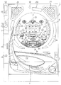
まず、遊技機の一例であるパチンコ遊技機の全体の構成について説明する。図1はパチンコ遊技機を正面からみた正面図、図2はガラス扉枠を取り外した状態での遊技盤の前面を示す正面図である。なお、以下の実施の形態では、パチンコ遊技機を例に説明を行うが、本発明による遊技機はパチンコ遊技機に限られず、例えばスロット機等であってもよい。また、画像式の遊技機に適用することもできる。
Hereinafter, an embodiment of the present invention will be described with reference to the drawings.
First, the overall configuration of a pachinko gaming machine that is an example of a gaming machine will be described. FIG. 1 is a front view of the pachinko gaming machine as viewed from the front, and FIG. 2 is a front view showing the front of the game board with the glass door frame removed. In the following embodiments, a pachinko gaming machine will be described as an example. However, the gaming machine according to the present invention is not limited to a pachinko gaming machine, and may be, for example, a slot machine. It can also be applied to image-type gaming machines.
パチンコ遊技機1は、縦長の方形状に形成された外枠(図示せず)と、外枠の内側に開閉可能に取り付けられた遊技枠とで構成される。また、パチンコ遊技機1は、遊技枠に開閉可能に設けられている額縁状に形成されたガラス扉枠2を有する。遊技枠は、外枠に対して開閉自在に設置される前面枠(図示せず)と、機構部品等が取り付けられる機構板と、それらに取り付けられる種々の部品(後述する遊技盤を除く。)とを含む構造体である。
The
図1に示すように、パチンコ遊技機1は、額縁状に形成されたガラス扉枠2を有する。ガラス扉枠2の下部表面には打球供給皿(上皿)3がある。打球供給皿3の下部には、打球供給皿3に収容しきれない遊技球を貯留する余剰球受皿4と打球を発射する打球操作ハンドル(操作ノブ)5が設けられている。ガラス扉枠2の背面には、遊技盤6が着脱可能に取り付けられている。なお、遊技盤6は、それを構成する板状体と、その板状体に取り付けられた種々の部品とを含む構造体である。また、遊技盤6の前面には遊技領域7が形成されている。
As shown in FIG. 1, the
遊技領域7の中央付近には、それぞれが識別情報としての図柄を可変表示する複数の可変表示部を含む可変表示装置(特別図柄表示装置)9が設けられている。可変表示装置9には、例えば「左」、「中」、「右」の3つの可変表示部(図柄表示エリア)がある。可変表示装置9の下方には、始動入賞口14が設けられている。始動入賞口14に入った入賞球は、遊技盤6の背面に導かれ、始動口スイッチ14aによって検出される。また、始動入賞口14の下部には開閉動作を行う可変入賞球装置15が設けられている。可変入賞球装置15は、ソレノイド16によって開状態とされる。
Near the center of the
可変入賞球装置15の下部には、特定遊技状態(大当り状態)においてソレノイド21によって開状態とされる開閉板20が設けられている。開閉板20は大入賞口を開閉する手段である。開閉板20から遊技盤6の背面に導かれた入賞球のうち一方(V入賞領域)に入った入賞球はV入賞スイッチ22で検出され、開閉板20からの入賞球はカウントスイッチ23で検出される。遊技盤6の背面には、大入賞口内の経路を切り換えるためのソレノイド21Aも設けられている。また、可変表示装置9の下部には、始動入賞口14に入った有効入賞球数すなわち始動記憶数を表示する4個の表示部を有する始動記憶表示器18が設けられている。この例では、4個を上限として、有効始動入賞がある毎に、始動記憶表示器18は点灯している表示部を1つずつ増やす。そして、可変表示装置9の可変表示が開始される毎に、点灯している表示部を1つ減らす。
An open /
ゲート32に遊技球が入賞すると、7セグメントLEDによる普通図柄表示器10の表示の可変表示が開始される。そして、普通図柄表示器10における停止図柄が所定の図柄(当り図柄)である場合に、可変入賞球装置15が所定回数、所定時間だけ開状態になる。普通図柄表示器10の近傍には、ゲート32に入った入賞球数を表示する4個の表示部を有する普通図柄始動記憶表示器41が設けられている。この例では、4個を上限として、ゲート32への入賞がある毎に、普通図柄始動記憶表示器41は点灯している表示部を1つずつ増やす。そして、可変入賞球装置15の開放制御がなされる毎に、点灯している表示部を1つ減らす。
When a game ball wins the
遊技盤6には、複数の入賞口24,29,30,33が設けられ、遊技球の入賞口24,29,30,33への入賞は、それぞれ入賞口スイッチ24a,29a,30a,33aによって検出される。遊技領域7の左右周辺には、遊技中に点滅表示される装飾ランプ25が設けられ、下部には、入賞しなかった打球を吸収するアウト口26がある。また、遊技領域7の外側の左右上部には、効果音を発する2つのスピーカ27が設けられている。遊技領域7の外周には、天枠ランプ28a、左枠ランプ28bおよび右枠ランプ28cが設けられている。さらに、遊技領域7における各構造物(大入賞口等)の周囲には装飾LEDが設置されている。
The
そして、この例では、左枠ランプ28bの近傍に、賞球残数があるときに点灯する賞球ランプ51が設けられ、天枠ランプ28aの近傍に、補給球が切れたときに点灯する球切れランプ52が設けられている。さらに、図1には、パチンコ遊技機1に隣接して設置され、プリペイドカードが挿入されることによって球貸しを可能にするカードユニット50も示されている。
In this example, a
カードユニット50には、使用可能状態であるか否かを示す使用可表示ランプ151、カード内に記録された残額情報に端数(100円未満の数)が存在する場合にその端数を打球供給皿3の近傍に設けられる度数表示LEDに表示させるための端数表示スイッチ152、カードユニット50がいずれの側のパチンコ遊技機1に対応しているのかを示す連結台方向表示器153、カードユニット50内にカードが投入されていることを示すカード投入表示ランプ154、記録媒体としてのカードが挿入されるカード挿入口155、およびカード挿入口155の裏面に設けられているカードリーダライタの機構を点検する場合にカードユニット50を解放するためのカードユニット錠156が設けられている。
The
打球発射装置から発射された遊技球は、打球レールを通って遊技領域7に入り、その後、遊技領域7を下りてくる。打球が始動入賞口14に入り始動口スイッチ14aで検出されると、図柄の可変表示を開始できる状態であれば、可変表示装置9において特別図柄が可変表示(変動)を始める。図柄の可変表示を開始できる状態でなければ、始動記憶数を1増やす。
The game balls launched from the hit ball launching device enter the
可変表示装置9における特別図柄の可変表示は、一定時間が経過したときに停止する。停止時の特別図柄の組み合わせが大当り図柄の組み合わせであると、大当り遊技状態に移行する。すなわち、開閉板20が、一定時間経過するまで、または、所定個数(例えば10個)の打球が入賞するまで開放する。そして、開閉板20の開放中に打球がV入賞領域に入賞しV入賞スイッチ22で検出されると、継続権が発生し開閉板20の開放が再度行われる。継続権の発生は、所定回数(例えば15ラウンド)許容される。
The variable display of the special symbol on the
停止時の可変表示装置9における特別図柄の組み合わせが確率変動を伴う大当り図柄の組み合わせである場合には、次に大当りとなる確率が高くなる。すなわち、高確率状態という遊技者にとってさらに有利な状態となる。
When the combination of special symbols in the
打球がゲート32に入賞すると、普通図柄表示器10において普通図柄としての表示数字が連続的に変化する状態になる。また、普通図柄表示器10における停止図柄が所定の図柄(当り図柄)である場合に、可変入賞球装置15が所定時間だけ開状態になる。さらに、高確率状態では、普通図柄表示器10における停止図柄が当り図柄になる確率が高められるとともに、可変入賞球装置15の開放時間と開放回数が高められる。
When the hit ball wins the
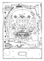
次に、パチンコ遊技機1の裏面の構造について図3および図4を参照して説明する。図3は、遊技機を裏面から見た背面図である。図4は、各種部材が取り付けられた機構板を遊技機背面側から見た背面図である。
Next, the structure of the back surface of the
図3に示すように、遊技機裏面側では、可変表示装置9を制御する図柄制御基板80を含む可変表示制御ユニット49、遊技制御用マイクロコンピュータ等が搭載された遊技制御基板(主基板)31が設置されている。また、球払出制御を行う払出制御用マイクロコンピュータ等が搭載された払出制御基板37が設置されている。さらに、遊技盤6に設けられている各種装飾LED、特別図柄始動記憶表示器18および普通図柄始動記憶表示器41、装飾ランプ25、枠側に設けられている天枠ランプ28a、左枠ランプ28b、右枠ランプ28c、賞球ランプ51および球切れランプ52を点灯制御するランプ制御手段が搭載されたランプ制御基板35、スピーカ27からの音発生を制御する音制御手段が搭載された音制御基板70も設けられている。また、DC30V、DC21V、DC12VおよびDC5Vを作成する電源回路が搭載された電源基板910や発射制御基板91が設けられている。
As shown in FIG. 3, on the back side of the gaming machine, a game control board (main board) 31 on which a variable
遊技機裏面において、上方には、各種情報を遊技機外部に出力するための各端子を備えたターミナル基板160が設置されている。ターミナル基板160には、少なくとも、球切れ検出スイッチの出力を導入して外部出力するための球切れ用端子、賞球個数信号を外部出力するための賞球用端子および球貸し個数信号を外部出力するための球貸し用端子が設けられている。また、中央付近には、主基板31からの各種情報を遊技機外部に出力するための各端子を備えた情報端子盤34が設置されている。
On the back side of the gaming machine, a
さらに、各基板(主基板31や払出制御基板37等)に含まれる記憶内容保持手段(例えば、電力供給停止時にもその内容を保持可能なバックアップRAM)に記憶されたバックアップデータをクリアするための初期化操作手段としてのクリアスイッチ921が搭載されたスイッチ基板190が設けられている。スイッチ基板190には、クリアスイッチ921と、主基板31等の他の基板と接続されるコネクタ922が設けられている。
Furthermore, for clearing backup data stored in storage content holding means (for example, a backup RAM capable of holding the contents even when power supply is stopped) included in each board (
貯留タンク38に貯留された遊技球は誘導レール39を通り、図4に示されるように、カーブ樋186を経て賞球ケース40Aで覆われた球払出装置に至る。球払出装置の上部には、遊技媒体切れ検出手段としての球切れスイッチ187が設けられている。球切れスイッチ187が球切れを検出すると、球払出装置の払出動作が停止する。球切れスイッチ187は遊技球通路内の遊技球の有無を検出するスイッチであるが、貯留タンク38内の補給球の不足を検出する球切れ検出スイッチ167も誘導レール39における上流部分(貯留タンク38に近接する部分)に設けられている。球切れ検出スイッチ167が遊技球の不足を検知すると、遊技機設置島に設けられている補給機構から遊技機に対して遊技球の補給が行われる。
The game balls stored in the
なお、球切れスイッチ187は、球払出装置に至る払出球通路に27〜28個程度の遊技球が存在することを検出できるような位置に係止されている。すなわち、球切れスイッチ187は、賞球の一単位の最大払出量(この実施の形態では15個)および球貸しの一単位の最大払出量(この実施の形態では100円:25個)以上が確保されていることが確認できるような位置に設置されている。
The ball break
球払出装置から払い出された遊技球は、連絡口45を通ってパチンコ遊技機1の前面に設けられている打球供給皿3に誘導される。連絡口45の側方には、パチンコ遊技機1の前面に設けられている余剰球受皿4に連通する余剰球通路46が形成されている。
The game ball paid out from the ball payout device is guided to the hitting
入賞にもとづく景品としての遊技球や球貸し要求にもとづく遊技球が多数払い出されて打球供給皿3が満杯になり、ついには遊技球が連絡口45に到達した後さらに遊技球が払い出されると、遊技球は、余剰球通路46を経て余剰球受皿4に導かれる。さらに遊技球が払い出されると、感知レバー47が貯留状態検出手段としての満タンスイッチ48を押圧して、貯留状態検出手段としての満タンスイッチ48がオンする。すなわち、遊技者側貯留手段としての余剰球受皿4における貯留量が貯留許容量を越えたことが、満タンスイッチ48で検出される。その状態では、球払出装置内の払出モータの回転が停止して球払出装置の動作が停止するとともに発射装置の駆動も停止する。
A large number of game balls as prizes based on winning prizes and game balls based on ball lending requests are paid out and the hitting
図4に示すように、球払出装置の側方には、カーブ樋186から遊技機下部の排出口192に至る球抜き通路191が形成されている。球抜き通路191の上部には球抜きレバー193が設けられ、球抜きレバー193が遊技店員等によって操作されると、誘導レール39から球抜き通路191への遊技球通路が形成され、貯留タンク38内に貯留されている遊技球は、排出口192から遊技機外に排出される。
As shown in FIG. 4, a
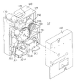
図5は、球払出装置97の構成例を示す分解斜視図である。この例では、賞球ケース40Aとしての3つのケース140,141,142の内部に球払出装置97が形成されている。ケース140,141の上部には、球切れスイッチ187の下部の球通路と連通する穴170,171が設けられ、遊技球は、穴170,171から球払出装置97に流入する。
FIG. 5 is an exploded perspective view showing a configuration example of the
球払出装置97は駆動源となる払出モータ(例えばステッピングモータ)289を含む。払出モータ289の回転力は、払出モータ289の回転軸に嵌合しているギア290に伝えられ、さらに、ギア290と噛み合うギア291に伝えられる。ギア291の中心軸には、凹部を有するスプロケット292が嵌合している。穴170,171から流入した遊技球は、スプロケット292の凹部によって、スプロケット292の下方の球通路293に1個ずつ落下させられる。
The
球通路293には遊技球の流下路を切り替えるための振分部材311が設けられている。振分部材311はソレノイド310によって駆動され、賞球払出時には、球通路293における一方の流下路を遊技球が流下するように倒れ、球貸し時には球通路293における他方の流下路を遊技球が流下するように倒れる。なお、払出モータ289およびソレノイド310は、払出制御基板37に搭載されている払出制御用CPUによって制御される。また、払出制御用CPUは、主基板31に搭載されている遊技制御用のCPUからの指令に応じて払出モータ289およびソレノイド310を制御する。
The
賞球払出時に選択される流下路の下方には球払出装置によって払い出された遊技球を検出する賞球センサ(賞球カウントスイッチ)301Aが設けられ、球貸し時に選択される流下路の下方には球払出装置によって払い出された遊技球を検出する球貸しセンサ(球貸しカウントスイッチ)301Bが設けられている。賞球カウントスイッチ301Aの検出信号と球貸しカウントスイッチ301Bの検出信号は払出制御基板37の払出制御用CPUに入力される。払出制御用CPUは、それらの検出信号にもとづいて、実際に払い出された遊技球の個数を計数する。
A prize ball sensor (prize ball count switch) 301A for detecting a game ball paid out by the ball payout device is provided below the flow path selected at the time of paying out the winning ball, and below the flow path selected at the time of lending the ball. Is provided with a ball lending sensor (ball lending count switch) 301B for detecting a game ball paid out by the ball paying device. The detection signal of the winning
図6は、主基板31における回路構成の一例を示すブロック図である。なお、図6には、払出制御基板37、ランプ制御基板35、音制御基板70、発射制御基板91および図柄制御基板80も示されている。主基板31には、プログラムに従ってパチンコ遊技機1を制御する基本回路53と、ゲートスイッチ32a、始動口スイッチ14a、V入賞スイッチ22、カウントスイッチ23、入賞口スイッチ24a,29a,30a,33a、満タンスイッチ48、球切れスイッチ187、賞球カウントスイッチ301Aおよびクリアスイッチ921からの信号を基本回路53に与えるスイッチ回路58と、可変入賞球装置15を開閉するソレノイド16、開閉板20を開閉するソレノイド21および大入賞口内の経路を切り換えるためのソレノイド21Aを基本回路53からの指令に従って駆動するソレノイド回路59とが搭載されている。
FIG. 6 is a block diagram illustrating an example of a circuit configuration in the
なお、図6には示されていないが、カウントスイッチ短絡信号もスイッチ回路58を介して基本回路53に伝達される。また、ゲートスイッチ32a、始動口スイッチ14a、V入賞スイッチ22、カウントスイッチ23、入賞口スイッチ24a,29a,30a,33a、満タンスイッチ48、球切れスイッチ187、賞球カウントスイッチ301A等のスイッチは、センサと称されているものでもよい。すなわち、遊技球を検出できる遊技媒体検出手段(この例では遊技球検出手段)であれば、その名称を問わない。
Although not shown in FIG. 6, the count switch short-circuit signal is also transmitted to the
また、基本回路53から与えられるデータに従って、大当りの発生を示す大当り情報、可変表示装置9における図柄の可変表示開始に利用された始動入賞球の個数を示す有効始動情報、確率変動が生じたことを示す確変情報等の情報出力信号をホールコンピュータ等の外部機器に対して出力する情報出力回路64が搭載されている。
Further, according to the data given from the
基本回路53は、ゲーム制御用のプログラム等を記憶するROM54、ワークメモリとして使用される記憶手段(変動データを記憶する手段)としてのRAM55、プログラムに従って制御動作を行うCPU56およびI/Oポート部57を含む。この実施の形態では、ROM54,RAM55はCPU56に内蔵されている。すなわち、CPU56は、1チップマイクロコンピュータである。なお、1チップマイクロコンピュータは、少なくともRAM55が内蔵されていればよく、ROM54およびI/Oポート部57は外付けであっても内蔵されていてもよい。
The
また、RAM(CPU内蔵RAMであってもよい。)55の一部または全部が、電源基板910において作成されるバックアップ電源よってバックアップされているバックアップRAMである。すなわち、遊技機に対する電力供給が停止しても、所定期間は、RAM55の一部または全部の内容は保存される。
Further, a part or all of the RAM (may be a CPU built-in RAM) 55 is a backup RAM that is backed up by a backup power source created in the
遊技球を打撃して発射する打球発射装置は発射制御基板91上の回路によって制御される駆動モータ94で駆動される。そして、駆動モータ94の駆動力は、操作ノブ5の操作量に従って調整される。すなわち、発射制御基板91上の回路によって、操作ノブ5の操作量に応じた速度で打球が発射されるように制御される。
A ball hitting device for hitting and launching a game ball is driven by a
なお、この実施の形態では、ランプ制御基板35に搭載されているランプ制御手段が、遊技盤に設けられている始動記憶表示器18、普通図柄始動記憶表示器41および装飾ランプ25の表示制御を行うとともに、枠側に設けられている天枠ランプ28a、左枠ランプ28b、右枠ランプ28c、賞球ランプ51および球切れランプ52の表示制御を行う。また、特別図柄を可変表示する可変表示装置9および普通図柄を可変表示する普通図柄表示器10の表示制御は、図柄制御基板80に搭載されている表示制御手段によって行われる。
In this embodiment, the lamp control means mounted on the
図7は、図柄制御基板80内の回路構成を、可変表示装置9の一実現例であるLCD(液晶表示装置)82、普通図柄表示器10、主基板31の出力ポート(ポート0,2)570,572および出力バッファ回路620,62Aとともに示すブロック図である。出力ポート(出力ポート2)572からは8ビットの表示制御コマンドを構成するコマンドデータが出力され、出力ポート570からは1ビットのストローブ信号(INT信号)が出力される。INT信号は、コマンドデータの取り込みを指令する取込信号である
FIG. 7 shows the circuit configuration in the
表示制御用CPU101は、制御データROM102に格納されたプログラムに従って動作し、主基板31からノイズフィルタ107および入力バッファ回路105Bを介してINT信号が入力されると、入力バッファ回路105Aを介して表示制御コマンドを受信する。入力バッファ回路105A,105Bとして、例えば汎用ICである74HC540,74HC14を使用することができる。なお、表示制御用CPU101がI/Oポートを内蔵していない場合には、入力バッファ回路105A,105Bと表示制御用CPU101との間に、I/Oポートが設けられる。
The display control CPU 101 operates in accordance with a program stored in the
そして、表示制御用CPU101は、受信した表示制御コマンドに従って、LCD82に表示される画面の表示制御を行う。具体的には、表示制御コマンドに応じた指令をVDP103に与える。VDP103は、キャラクタROM86から必要なデータを読み出す。VDP103は、入力したデータに従ってLCD82に表示するための画像データを生成し、R,G,B信号および同期信号をLCD82に出力する。
Then, the display control CPU 101 performs display control of the screen displayed on the
なお、図7には、VDP103をリセットするためのリセット回路83、VDP103に動作クロックを与えるための発振回路85、および使用頻度の高い画像データを格納するキャラクタROM86も示されている。キャラクタROM86に格納される使用頻度の高い画像データとは、例えば、LCD82に表示される人物、動物、または、文字、図形もしくは記号等からなる画像などである。
7 also shows a reset circuit 83 for resetting the
入力バッファ回路105A,105Bは、主基板31から図柄制御基板80へ向かう方向にのみ信号を通過させることができる。従って、図柄制御基板80側から主基板31側に信号が伝わる余地はない。すなわち、入力バッファ回路105A,105Bは、入力ポートともに不可逆性情報入力手段を構成する。図柄制御基板80内の回路に不正改造が加えられても、不正改造によって出力される信号が主基板31側に伝わることはない。
The input buffer circuits 105A and 105B can pass signals only in the direction from the
高周波信号を遮断するノイズフィルタ107として、例えば3端子コンデンサやフェライトビーズが使用されるが、ノイズフィルタ107の存在によって、表示制御コマンドに基板間でノイズが乗ったとしても、その影響は除去される。また、主基板31のバッファ回路620,62Aの出力側にもノイズフィルタを設けてもよい。
For example, a three-terminal capacitor or a ferrite bead is used as the
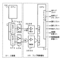
図8は、主基板31およびランプ制御基板35における信号送受信部分を示すブロック図である。この実施の形態では、遊技盤6に設けられている各種装飾LED、特別図柄始動記憶表示器18および普通図柄始動記憶表示器41、装飾ランプ25、枠側に設けられている天枠ランプ28a、左枠ランプ28b、右枠ランプ28c、賞球ランプ51および球切れランプ52の点灯/消灯とを示すランプ制御コマンドが主基板31からランプ制御基板35に出力される。
FIG. 8 is a block diagram showing signal transmission / reception portions in the
図8に示すように、ランプ制御に関するランプ制御コマンドは、基本回路53におけるI/Oポート部57の出力ポート(出力ポート0,3)570,573から出力される。出力ポート(出力ポート3)573は8ビットのランプ制御コマンドを構成するコマンドデータを出力し、出力ポート570は1ビットのINT信号を出力する。ランプ制御基板35において、主基板31からの制御コマンドは、入力バッファ回路355A,355Bを介してランプ制御用CPU351に入力する。なお、ランプ制御用CPU351がI/Oポートを内蔵していない場合には、入力バッファ回路355A,355Bとランプ制御用CPU351との間に、I/Oポートが設けられる。
As shown in FIG. 8, the lamp control command related to the lamp control is output from the output ports (
ランプ制御基板35において、ランプ制御用CPU351は、各制御コマンドに応じて定義されている各種装飾LED、装飾ランプ25、枠側に設けられている天枠ランプ28a、左枠ランプ28b、右枠ランプ28cに対して点灯/消灯信号を出力する。点灯/消灯信号は、各ランプ・LEDに出力される。なお、点灯/消灯パターンは、ランプ制御用CPU351の内蔵ROMまたは外付けROMに記憶されている。
In the
主基板31において、CPU56は、RAM55の記憶内容に未払出の賞球残数があるときに賞球ランプ51の点灯を指示するランプ制御コマンドを出力し、遊技盤裏面の補給球通路に設置されている球切れスイッチ187(図4参照)が遊技球を検出しなくなると球切れランプ52の点灯を指示するランプ制御コマンドを出力する。ランプ制御基板35において、各ランプ制御コマンドは、入力バッファ回路355A,355Bを介してランプ制御用CPU351に入力する。ランプ制御用CPU351は、それらの制御コマンドに応じて、賞球ランプ51および球切れランプ52を点灯/消灯する。なお、点灯/消灯パターンは、ランプ制御用CPU351の内蔵ROMまたは外付けROMに記憶されている。
In the
さらに、ランプ制御用CPU351は、ランプ制御コマンドに応じて始動記憶表示器18および普通図柄始動記憶表示器41に対して点灯/消灯信号を出力する。
Further, the lamp control CPU 351 outputs a light on / off signal to the
入力バッファ回路355A,355Bとして、例えば、汎用のCMOS−ICである74HC540,74HC14が用いられる。入力バッファ回路355A,355Bは、主基板31からランプ制御基板35へ向かう方向にのみ信号を通過させることができる。従って、ランプ制御基板35側から主基板31側に信号が伝わる余地はない。たとえ、ランプ制御基板35内の回路に不正改造が加えられても、不正改造によって出力される信号がメイン基板31側に伝わることはない。なお、入力バッファ回路355A,355Bの入力側にノイズフィルタを設けてもよい。
As the
また、主基板31において、出力ポート570,573の外側にバッファ回路620,63Aが設けられている。バッファ回路620,63Aとして、例えば、汎用のCMOS−ICである74HC250,74HC14が用いられる。このような構成によれば、外部から主基板31の内部に入力される信号が阻止されるので、ランプ制御基板70から主基板31に信号が与えられる可能性がある信号ラインをさらに確実になくすことができる。なお、バッファ回路620,63Aの出力側にノイズフィルタを設けてもよい。
In the
図9は、主基板31における音制御コマンドの信号送信部分および音制御基板70の構成例を示すブロック図である。この実施の形態では、遊技進行に応じて、遊技領域7の外側に設けられているスピーカ27の音声出力を指示するための音制御コマンドが、主基板31から音制御基板70に出力される。
FIG. 9 is a block diagram showing a configuration example of the sound control command signal transmission part of the
図9に示すように、音制御コマンドは、基本回路53におけるI/Oポート部57の出力ポート(出力ポート0,4)570,574から出力される。出力ポート(出力ポート4)574からは8ビットのデータが出力され、出力ポート570からは1ビットのINT信号が出力される。音制御基板70において、主基板31からの各信号は、入力バッファ回路705A,705Bを介して音制御用CPU701に入力する。なお、音制御用CPU701がI/Oポートを内蔵していない場合には、入力バッファ回路705A,705Bと音制御用CPU701との間に、I/Oポートが設けられる。
As shown in FIG. 9, the sound control command is output from the output ports (
そして、例えばディジタルシグナルプロセッサによる音声合成回路702は、音制御用CPU701の指示に応じた音声や効果音を発生し音量切替回路703に出力する。音量切替回路703は、音制御用CPU701の出力レベルを、設定されている音量に応じたレベルにして音量増幅回路704に出力する。音量増幅回路704は、増幅した音声信号をスピーカ27に出力する。
Then, for example, a
入力バッファ回路705A,705Bとして、例えば、汎用のCMOS−ICである74HC540,74HC14が用いられる。入力バッファ回路705A,705Bは、主基板31から音制御基板70へ向かう方向にのみ信号を通過させることができる。よって、音制御基板70側から主基板31側に信号が伝わる余地はない。従って、音制御基板70内の回路に不正改造が加えられても、不正改造によって出力される信号が主基板31側に伝わることはない。なお、入力バッファ回路705A,705Bの入力側にノイズフィルタを設けてもよい。
As the
また、主基板31において、出力ポート570,574の外側にバッファ回路620,67Aが設けられている。バッファ回路620,67Aとして、例えば、汎用のCMOS−ICである74HC250,74HC14が用いられる。このような構成によれば、外部から主基板31の内部に入力される信号が阻止されるので、音制御基板70から主基板31に信号が与えられる可能性がある信号ラインをさらに確実になくすことができる。なお、バッファ回路620,67Aの出力側にノイズフィルタを設けてもよい。
In the
図10は、払出制御基板37および球払出装置97の構成要素などの払出に関連する構成要素を示すブロック図である。図10に示すように、満タンスイッチ48からの検出信号は、中継基板71を介して主基板31のI/Oポート部57に入力される。また、球切れスイッチ187からの検出信号も、中継基板72および中継基板71を介して主基板31のI/Oポート部57に入力される。
FIG. 10 is a block diagram showing components related to payout, such as components of the
主基板31のCPU56は、球切れスイッチ187からの検出信号が球切れ状態を示しているか、または、満タンスイッチ48からの検出信号が満タン状態を示していると、払出を停止すべき状態であることを指示する払出制御コマンドを送信する。払出を停止すべき状態であることを指示する払出制御コマンドを受信すると、払出制御基板37の払出制御用CPU371は球払出処理を停止する。
The
さらに、賞球カウントスイッチ301Aからの検出信号は、中継基板72および中継基板71を介して主基板31のI/Oポート部57に入力されるとともに、中継基板72を介して払出制御基板37の入力ポート372bに入力される。賞球カウントスイッチ301Aは、球払出装置97の払出機構部分に設けられ、実際に払い出された賞球払出球を検出する。
Further, the detection signal from the prize
入賞があると、払出制御基板37には、主基板31の出力ポート(ポート0,1)570,571から賞球個数を示す払出制御コマンドが入力される。出力ポート(出力ポート1)571は8ビットのデータを出力し、出力ポート570は1ビットのINT信号を出力する。賞球個数を示す払出制御コマンドは、入力バッファ回路373Aを介してI/Oポート372aに入力される。INT信号は、入力バッファ回路373Bを介して払出制御用CPU371の割込端子に入力されている。払出制御用CPU371は、I/Oポート372aを介して払出制御コマンドを入力し、払出制御コマンドに応じて球払出装置97を駆動して賞球払出を行う。なお、この実施の形態では、払出制御用CPU371は、1チップマイクロコンピュータであり、少なくともRAMが内蔵されている。
When there is a winning, a payout control command indicating the number of winning balls is input to the
また、主基板31において、出力ポート570,571の外側にバッファ回路620,68Aが設けられている。バッファ回路620,68Aとして、例えば、汎用のCMOS−ICである74HC250,74HC14が用いられる。このような構成によれば、外部から主基板31の内部に入力される信号が阻止されるので、払出制御基板37から主基板31に信号が与えられる可能性がある信号ラインをさらに確実になくすことができる。なお、バッファ回路620,68Aの出力側にノイズフィルタを設けてもよい。
In the
払出制御用CPU371は、出力ポート372cを介して、貸し球数を示す球貸し個数信号をターミナル基板160に出力する。さらに、出力ポート372dを介して、エラー表示用LED374にエラー信号を出力する。
The payout control CPU 371 outputs a ball lending number signal indicating the number of lending balls to the
さらに、払出制御基板37の入力ポート372bには、中継基板72を介して、球貸しカウントスイッチ301B、および払出モータ289の回転位置を検出するための払出モータ位置センサからの検出信号が入力される。球貸しカウントスイッチ301Bは、球払出装置97の払出機構部分に設けられ、実際に払い出された貸し球を検出する。払出制御基板37からの払出モータ289への駆動信号はあ、出力ポート372cおよび中継基板72を介して球払出装置97の払出機構部分における払出モータ289に伝えられ、振分ソレノイド310への駆動信号は、出力ポート372eおよび中継基板72を介して球払出装置97の払出機構部分における振分ソレノイド310に伝えられる。また、クリアスイッチ921の出力も、入力ポート372bに入力される。
Further, a detection signal from the payout motor position sensor for detecting the rotational position of the ball lending
カードユニット50には、カードユニット制御用マイクロコンピュータが搭載されている。また、カードユニット50には、端数表示スイッチ152、連結台方向表示器153、カード投入表示ランプ154およびカード挿入口155が設けられている(図1参照)。残高表示基板74には、打球供給皿3の近傍に設けられている度数表示LED、球貸しスイッチおよび返却スイッチが接続される。
The
残高表示基板74からカードユニット50には、遊技者の操作に応じて、球貸しスイッチ信号および返却スイッチ信号が払出制御基板37を介して与えられる。また、カードユニット50から残高表示基板74には、プリペイドカードの残高を示すカード残高表示信号および球貸し可表示信号が払出制御基板37を介して与えられる。カードユニット50と払出制御基板37の間では、接続信号(VL信号)、ユニット操作信号(BRDY信号)、球貸し要求信号(BRQ信号)、球貸し完了信号(EXS信号)およびパチンコ機動作信号(PRDY信号)が入力ポート372bおよび出力ポート372eを介してやりとりされる。
A ball lending switch signal and a return switch signal are given from the
パチンコ遊技機1の電源が投入されると、払出制御基板37の払出制御用CPU371は、カードユニット50にPRDY信号を出力する。また、カードユニット制御用マイクロコンピュータは、VL信号を出力する。払出制御用CPU371は、VL信号の入力状態により接続状態/未接続状態を判定する。カードユニット50においてカードが受け付けられ、球貸しスイッチが操作され球貸しスイッチ信号が入力されると、カードユニット制御用マイクロコンピュータは、払出制御基板37にBRDY信号を出力する。この時点から所定の遅延時間が経過すると、カードユニット制御用マイクロコンピュータは、払出制御基板37にBRQ信号を出力する。
When the power of the
そして、払出制御基板37の払出制御用CPU371は、カードユニット50に対するEXS信号を立ち上げ、カードユニット50からのBRQ信号の立ち下がりを検出すると、払出モータ289を駆動し、所定個の貸し球を遊技者に払い出す。このとき、振分ソレノイド310は駆動状態とされている。すなわち、球振分部材311を球貸し側に向ける。そして、払出が完了したら、払出制御用CPU371は、カードユニット50に対するEXS信号を立ち下げる。その後、カードユニット50からのBRDY信号がオン状態でなければ、賞球払出制御を実行する。
Then, the payout control CPU 371 of the
以上のように、カードユニット50からの信号は全て払出制御基板37に入力される構成になっている。従って、球貸し制御に関して、カードユニット50から主基板31に信号が入力されることはなく、主基板31の基本回路53にカードユニット50の側から不正に信号が入力される余地はない。また、カードユニット50で用いられる電源電圧AC24Vは払出制御基板37から供給される。
As described above, all signals from the
この実施の形態では、電源基板910から払出制御基板37に対して電源断信号も入力される。電源断信号は、払出制御用CPU371のマスク不能割込(NMI)端子に入力される。さらに、払出制御基板37に存在するRAM(CPU内蔵RAMであってもよい。)の少なくとも一部は、電源基板910において作成されるバックアップ電源によって、バックアップされている。すなわち、遊技機に対する電力供給が停止しても、所定期間は、RAMの少なくとも一部の内容は保存される。
In this embodiment, a power-off signal is also input from the
なお、この実施の形態では、カードユニット50が遊技機とは別体として遊技機に隣接して設置されている場合を例にするが、カードユニット50は遊技機と一体化されていてもよい。また、コイン投入に応じてその金額に応じた遊技球が貸し出されるような場合でも本発明を適用できる。
In this embodiment, the case where the
図11は、電源基板910の一構成例を示すブロック図である。電源基板910は、主基板31、図柄制御基板80、音制御基板70、ランプ制御基板35および払出制御基板37等の電気部品制御基板と独立して設置され、遊技機内の各電気部品制御基板および機構部品が使用する電圧を生成する。この例では、AC24V、VSL(DC+30V)、DC+21V、DC+12VおよびDC+5Vを生成する。また、バックアップ電源すなわち記憶保持手段となるコンデンサ916は、DC+5Vすなわち各基板上のIC等を駆動する電源のラインから充電される。なお、VSLは、整流回路912において、整流素子でAC24Vを整流昇圧することによって生成される。VSLは、ソレノイド駆動電源となる。
FIG. 11 is a block diagram illustrating a configuration example of the
トランス911は、交流電源からの交流電圧を24Vに変換する。AC24V電圧は、コネクタ915に出力される。また、整流回路912は、AC24Vから+30Vの直流電圧を生成し、DC−DCコンバータ913およびコネクタ915に出力する。DC−DCコンバータ913は、1つまたは複数のコンバータIC922(図11では1つのみを示す。)を有し、VSLにもとづいて+21V、+12Vおよび+5Vを生成してコネクタ915に出力する。コンバータIC922の入力側には、比較的大容量のコンデンサ923が接続されている。従って、外部からの遊技機に対する電力供給が停止したときに、+30V、+12V、+5V等の直流電圧は、比較的緩やかに低下する。コネクタ915は例えば中継基板に接続され、中継基板から各電気部品制御基板および機構部品に必要な電圧の電力が供給される。
The transformer 911 converts AC voltage from the AC power source into 24V. The AC 24V voltage is output to the
ただし、電源基板910に各電気部品制御基板に至る各コネクタを設け、電源基板910から、中継基板を介さずにそれぞれの基板に至る各電圧を供給するようにしてもよい。また、図11には1つのコネクタ915が代表して示されているが、コネクタは、各電気部品制御基板対応に設けられている。
However, each connector reaching each electric component control board may be provided on the
DC−DCコンバータ913からの+5Vラインは分岐してバックアップ+5Vラインを形成する。バックアップ+5Vラインとグラウンドレベルとの間には大容量のコンデンサ916が接続されている。コンデンサ916は、遊技機に対する電力供給が停止したときの電気部品制御基板のバックアップRAM(電源バックアップされているRAMすなわち電力供給停止時にも記憶内容保持状態となりうるバックアップ記憶手段)に対して記憶状態を保持できるように電力を供給するバックアップ電源となる。また、+5Vラインとバックアップ+5Vラインとの間に、逆流防止用のダイオード917が挿入される。なお、この実施の形態では、バックアップ用の+5Vは、主基板31および払出制御基板37に供給される。
The + 5V line from the DC-
また、電源基板910には、電源監視回路としての電源監視用IC902が搭載されている。電源監視用IC902は、VSL電圧を導入し、VSL電圧を監視することによって遊技機への電力供給停止の発生を検出する。具体的には、VSL電圧が所定値(この例では+22V)以下になったら、電力供給の停止が生ずるとして電源断信号を出力する。なお、監視対象の電源電圧は、各電気部品制御基板に搭載されている回路素子の電源電圧(この例では+5V)よりも高い電圧であることが好ましい。この例では、交流から直流に変換された直後の電圧であるVSLが用いられている。電源監視用IC902からの電源断信号は、主基板31や払出制御基板37等に供給される。主基板31に搭載されている遊技制御手段や払出制御基板37に搭載されている払出制御手段は、電源断信号の入力に応じて、バックアップRAMの記憶内容を保護するための処理である電力供給停止時処理を実行する。
The
電源監視用IC902が電力供給の停止を検知するための所定値は、通常時の電圧より低いが、各電気部品制御基板上のCPUが暫くの間動作しうる程度の電圧である。また、電源監視用IC902が、CPU等の回路素子を駆動するための電圧(この例では+5V)よりも高く、また、交流から直流に変換された直後の電圧を監視するように構成されているので、CPUが必要とする電圧に対して監視範囲を広げることができる。従って、より精密な監視を行うことができる。さらに、監視電圧としてVSL(+30V)を用いる場合には、遊技機の各種スイッチに供給される電圧が+12Vであることから、電源瞬断時のスイッチオン誤検出の防止も期待できる。すなわち、+30V電源の電圧を監視すると、+30V作成の以降に作られる+12Vが落ち始める以前の段階でそれの低下を検出できる。 The predetermined value for the power monitoring IC 902 to detect the stop of power supply is lower than the normal voltage, but is a voltage that allows the CPU on each electrical component control board to operate for a while. Further, the power monitoring IC 902 is configured to monitor a voltage that is higher than a voltage for driving a circuit element such as a CPU (+5 V in this example) and immediately after being converted from AC to DC. Therefore, the monitoring range can be expanded for the voltage required by the CPU. Therefore, more precise monitoring can be performed. Furthermore, when VSL (+ 30V) is used as the monitoring voltage, the voltage supplied to the various switches of the gaming machine is + 12V, so that it can be expected to prevent erroneous switch-on detection at the time of instantaneous power interruption. That is, when the voltage of the + 30V power supply is monitored, it is possible to detect a decrease in the level before + 12V created after the creation of + 30V starts to drop.
+12V電源の電圧が低下するとスイッチ出力がオン状態を呈するようになるが、+12Vより早く低下する+30V電源電圧を監視して電力供給の停止を認識すれば、スイッチ出力がオン状態を呈する前に電力供給回復待ちの状態に入ってスイッチ出力を検出しない状態となることができる。 When the voltage of the + 12V power supply decreases, the switch output becomes on. However, if the power supply voltage is monitored by monitoring the + 30V power supply voltage, which decreases faster than + 12V, and the power supply is stopped, the switch output is turned on. It is possible to enter a supply recovery waiting state and not detect the switch output.
また、電源監視用IC902は、電気部品制御基板とは別個の電源基板910に搭載されているので、電源監視回路から複数の電気部品制御基板に電源断信号を供給することができる。電源断信号を必要とする電気部品制御基板が幾つあっても電源監視手段は1つ設けられていればよいので、各電気部品制御基板における各電気部品制御手段が後述する復旧制御を行っても、遊技機のコストはさほど上昇しない。
Further, since the power monitoring IC 902 is mounted on the
なお、図11に示された構成では、電源監視用IC902の検出信号(電源断信号)は、バッファ回路918,919を介してそれぞれの電気部品制御基板(例えば主基板31と払出制御基板37)に伝達されるが、例えば、1つの検出信号を中継基板に伝達し、中継基板から各電気部品制御基板に同じ信号を分配する構成でもよい。また、電源断信号を必要とする基板数に応じたバッファ回路を設けてもよい。さらに、主基板31と払出制御基板37とに出力される電源断信号について、電源断信号を出力することになる電源監視回路の監視電圧を異ならせてもよい。
In the configuration shown in FIG. 11, the detection signal (power cut-off signal) of the power monitoring IC 902 is sent to the respective electric component control boards (for example, the
図12および図13は、この実施の形態における出力ポートの割り当てを示す説明図である。図12に示すように、出力ポート0は各電気部品制御基板に送信される制御コマンドのINT信号の出力ポートである。また、払出制御基板37に送信される払出制御コマンドの8ビットのデータは出力ポート1から出力され、図柄制御基板80に送信される表示制御コマンドの8ビットのデータは出力ポート2から出力され、ランプ制御基板35に送信されるランプ制御コマンドの8ビットのデータは出力ポート3から出力される。そして、図13に示すように、音制御基板70に送信される音制御コマンドの8ビットのデータは出力ポート4から出力される。
12 and 13 are explanatory diagrams showing output port assignment in this embodiment. As shown in FIG. 12, the
また、出力ポート5から、情報出力回路64を介して情報端子板34やターミナル基板160に至る各種情報出力用信号すなわち制御に関わる情報の出力データが出力される。そして、出力ポート6から、可変入賞球装置15を開閉するためのソレノイド16、大入賞口の開閉板2を開閉するためのソレノイド21、および大入賞口内の経路を切り換えるためのソレノイド21Aに対する駆動信号が出力される。
Further, various information output signals from the
図13に示すように、払出制御基板37、図柄制御基板80、ランプ制御基板35および音制御基板70に対して出力される各INT信号(払出制御信号INT、表示制御信号INT、ランプ制御信号INTおよび音制御信号INT)を出力する出力ポート(出力ポート0)と、払出制御コマンドのコマンドデータとしての払出制御信号CD0〜CD7、表示制御コマンドのコマンドデータとしての表示制御信号CD0〜CD7、ランプ制御コマンドのコマンドデータとしてのランプ制御信号CD0〜CD7および音制御コマンドのコマンドデータとしての音制御信号CD0〜CD7を出力する出力ポート(出力ポート1〜4)とは、別ポートである。
As shown in FIG. 13, each INT signal (payout control signal INT, display control signal INT, lamp control signal INT) output to the
従って、INT信号を出力する際に、誤って払出制御信号CD0〜CD7、表示制御信号CD0〜CD7、ランプ制御信号CD0〜CD7および音制御信号CD0〜CD7を変化させてしまう可能性が低減する。また、払出制御信号CD0〜CD7、表示制御信号CD0〜CD7、ランプ制御信号CD0〜CD7または音制御信号CD0〜CD7を出力する際に、誤ってINT信号を変化させてしまう可能性が低減する。その結果、主基板31の遊技制御手段から各電気部品制御基板に対するコマンドは、より確実に送信されることになる。さらに、各INT信号は、全て出力ポート0から出力されるように構成されているので、遊技制御手段のINT信号出力処理の負担が軽減される。
Therefore, when outputting the INT signal, the possibility that the payout control signals CD0 to CD7, the display control signals CD0 to CD7, the ramp control signals CD0 to CD7, and the sound control signals CD0 to CD7 are erroneously changed is reduced. Further, when outputting the payout control signals CD0 to CD7, the display control signals CD0 to CD7, the ramp control signals CD0 to CD7, or the sound control signals CD0 to CD7, the possibility of erroneously changing the INT signal is reduced. As a result, a command for each electric component control board is more reliably transmitted from the game control means of the
図14は、この実施の形態における入力ポートのビット割り当てを示す説明図である。図14に示すように、入力ポート0のビット0〜7には、それぞれ、入賞口スイッチ33a、24a,29a,30a、始動口スイッチ14a、カウントスイッチ23、V入賞スイッチ22、ゲートスイッチ32aの検出信号が入力される。また、入力ポート1のビット0〜4には、それぞれ、賞球カウントスイッチ301A、満タンスイッチ48、球切れスイッチ187の検出信号、カウントスイッチ短絡信号およびクリアスイッチ921の検出信号が入力される。なお、各スイッチからの検出信号は、スイッチ回路58において論理反転されている。このように、クリアスイッチ921の検出信号は、遊技球を検出するためのスイッチの検出信号が入力される入力ポート(8ビット)と同一の入力ポートに入力されている。
FIG. 14 is an explanatory diagram showing bit assignment of input ports in this embodiment. As shown in FIG. 14,
次に遊技機の動作について説明する。図15は、主基板31における遊技制御手段(CPU56およびROM,RAM等の周辺回路)が実行するメイン処理を示すフローチャートである。遊技機に対して電源が投入され、リセット端子の入力レベルがハイレベルになると、CPU56は、ステップS1以降のメイン処理を開始する。メイン処理において、CPU56は、まず、必要な初期設定を行う。
Next, the operation of the gaming machine will be described. FIG. 15 is a flowchart showing main processing executed by game control means (
初期設定処理において、CPU56は、まず、割込禁止に設定する(ステップS1)。次に、割込モードを割込モード2に設定し(ステップS2)、スタックポインタにスタックポインタ指定アドレスを設定する(ステップS3)。そして、内蔵デバイスレジスタの初期化を行う(ステップS4)。また、内蔵デバイス(内蔵周辺回路)であるCTC(カウンタ/タイマ)およびPIO(パラレル入出力ポート)の初期化(ステップS5)を行った後、RAMをアクセス可能状態に設定する(ステップS6)。
In the initial setting process, the
この実施の形態で用いられるCPU56は、I/Oポート(PIO)およびタイマ/カウンタ回路(CTC)も内蔵している。また、CTCは、2本の外部クロック/タイマトリガ入力CLK/TRG2,3と2本のタイマ出力ZC/TO0,1を備えている。
The
この実施の形態で用いられているCPU56には、マスク可能な割込のモードとして以下の3種類のモードが用意されている。なお、マスク可能な割込が発生すると、CPU56は、自動的に割込禁止状態に設定するとともに、プログラムカウンタの内容をスタックにセーブする。
The
割込モード0:割込要求を行った内蔵デバイスがRST命令(1バイト)またはCALL命令(3バイト)をCPUの内部データバス上に出力する。よって、CPU56は、RST命令に対応したアドレスまたはCALL命令で指定されるアドレスの命令を実行する。リセット時に、CPU56は自動的に割込モード0になる。よって、割込モード1または割込モード2に設定したい場合には、初期設定処理において、割込モード1または割込モード2に設定するための処理を行う必要がある。
Interrupt mode 0: The built-in device that issued the interrupt request outputs an RST instruction (1 byte) or a CALL instruction (3 bytes) on the internal data bus of the CPU. Therefore, the
割込モード1:割込が受け付けられると、常に0038(h)番地に飛ぶモードである。 Interrupt mode 1: In this mode, when an interrupt is accepted, the mode always jumps to address 0038 (h).
割込モード2:CPU56の特定レジスタ(Iレジスタ)の値(1バイト)と内蔵デバイスが出力する割込ベクタ(1バイト:最下位ビット0)から合成されるアドレスが、割込番地を示すモードである。すなわち、割込番地は、上位アドレスが特定レジスタの値とされ下位アドレスが割込ベクタとされた2バイトで示されるアドレスである。従って、任意の(飛び飛びではあるが)偶数番地に割込処理を設置することができる。各内蔵デバイスは割込要求を行うときに割込ベクタを送信する機能を有している。
Interrupt mode 2: A mode in which the address synthesized from the value (1 byte) of the specific register (I register) of the
よって、割込モード2に設定されると、各内蔵デバイスからの割込要求を容易に処理することが可能になり、また、プログラムにおける任意の位置に割込処理を設置することが可能になる。さらに、割込モード1とは異なり、割込発生要因毎のそれぞれの割込処理を用意しておくことも容易である。上述したように、この実施の形態では、初期設定処理のステップS2において、CPU56は割込モード2に設定される。
Therefore, when the interrupt
次いで、CPU56は、入力ポート1を介して入力されるクリアスイッチ921の出力信号の状態を1回だけ確認する(ステップS7)。その確認においてオンを検出した場合には、CPU56は、通常の初期化処理を実行する(ステップS11〜ステップS15)。クリアスイッチ921がオンである場合(押下されている場合)には、ローレベルのクリアスイッチ信号が出力されている。なお、入力ポート1では、クリアスイッチ信号のオン状態はハイレベルである(図14参照)。また、例えば、遊技店員は、クリアスイッチ921をオン状態にしながら遊技機に対する電力供給を開始することによって、容易に初期化処理を実行させることができる。すなわち、RAMクリア等を行うことができる。
Next, the
クリアスイッチ921がオンの状態でない場合には、遊技機への電力供給が停止したときにバックアップRAM領域のデータ保護処理(例えばパリティデータの付加等の電力供給停止時処理)が行われたか否か確認する(ステップS8)。この実施の形態では、電力供給の停止が生じた場合には、バックアップRAM領域のデータを保護するための処理が行われている。そのような保護処理が行われていた場合をバックアップありとする。そのような保護処理が行われていないことを確認したら、CPU56は初期化処理を実行する。
If the
この実施の形態では、バックアップRAM領域にバックアップデータがあるか否かは、電力供給停止時処理においてバックアップRAM領域に設定されるバックアップフラグの状態によって確認される。例えば、バックアップフラグ領域に「55H」が設定されていればバックアップあり(オン状態)を意味し、「55H」以外の値が設定されていればバックアップなし(オフ状態)を意味する。 In this embodiment, whether or not there is backup data in the backup RAM area is confirmed by the state of the backup flag set in the backup RAM area in the power supply stop process. For example, if “55H” is set in the backup flag area, it means that there is a backup (ON state), and if a value other than “55H” is set, it means that there is no backup (OFF state).
バックアップありを確認したら、CPU56は、バックアップRAM領域のデータチェック(この例ではパリティチェック)を行う(ステップS9)。この実施の形態では、クリアデータ(00)をチェックサムデータエリアにセットし、チェックサム算出開始アドレスをポインタにセットする。また、チェックサムの対象となるデータ数に対応するチェックサム算出回数をセットする。そして、チェックサムデータエリアの内容とポインタが指すRAM領域の内容との排他的論理和を演算する。演算結果をチェックサムデータエリアにストアするとともに、ポインタの値を1増やし、チェックサム算出回数の値を1減算する。以上の処理が、チェックサム算出回数の値が0になるまで繰り返される。チェックサム算出回数の値が0になったら、CPU56は、チェックサムデータエリアの内容の各ビットの値を反転し、反転後のデータをチェックサムとする。
After confirming that there is a backup, the
電力供給停止時処理において、上記の処理と同様の処理によってチェックサムが算出され、チェックサムはバックアップRAM領域に保存されている。ステップS9では、算出したチェックサムと保存されているチェックサムとを比較する。不測の停電等の電力供給停止が生じた後に復旧した場合には、バックアップRAM領域のデータは保存されているはずであるから、チェック結果(比較結果)は正常(一致)になる。チェック結果が正常でないということは、バックアップRAM領域のデータが、電力供給停止時のデータとは異なっていることを意味する。そのような場合には、内部状態を電力供給停止時の状態に戻すことができないので、電力供給の停止からの復旧時でない電源投入時に実行される初期化処理を実行する。 In the power supply stop process, a checksum is calculated by the same process as described above, and the checksum is stored in the backup RAM area. In step S9, the calculated checksum is compared with the stored checksum. When the power supply is stopped after an unexpected power outage or the like, the data in the backup RAM area should be saved, so the check result (comparison result) is normal (matched). That the check result is not normal means that the data in the backup RAM area is different from the data when the power supply is stopped. In such a case, since the internal state cannot be returned to the state when the power supply is stopped, an initialization process that is executed when the power is turned on is not performed when the power supply is stopped.
チェック結果が正常であれば、CPU56は、遊技制御手段の内部状態と表示制御手段等の電気部品制御手段の制御状態を電力供給停止時の状態に戻すための遊技状態復旧処理を行う(ステップS10)。そして、バックアップRAM領域に保存されていたPC(プログラムカウンタ)の退避値がPCに設定され、そのアドレスに復帰する。
If the check result is normal, the
このように、バックアップフラグとチェックサム等のチェックデータとを用いてバックアップRAM領域のデータが保存されているか否かを確認することによって、遊技状態を電力供給停止時の状態に正確に戻すことができる。すなわち、バックアップRAM領域のデータにもとづく状態復旧処理の確実性が向上する。なお、この実施の形態では、バックアップフラグとチェックデータとの双方を用いてバックアップRAM領域のデータが保存されているか否かを確認しているが、いずれか一方のみを用いてもよい。すなわち、バックアップフラグとチェックデータとのいずれかを、状態復旧処理を実行するための契機としてもよい。 In this way, it is possible to accurately return the gaming state to the state when the power supply is stopped by checking whether the data in the backup RAM area is stored using the backup flag and check data such as a checksum. it can. That is, the certainty of the state restoration process based on the data in the backup RAM area is improved. In this embodiment, it is confirmed whether or not the data in the backup RAM area is stored by using both the backup flag and the check data, but only one of them may be used. That is, either the backup flag or the check data may be used as an opportunity for executing the state recovery process.
初期化処理では、CPU56は、まず、RAMクリア処理を行う(ステップS11)。また、所定の作業領域(例えば、普通図柄判定用乱数カウンタ、普通図柄判定用バッファ、特別図柄左中右図柄バッファ、特別図柄プロセスフラグ、払出コマンド格納ポインタ、賞球中フラグ、球切れフラグ、払出停止フラグなど制御状態に応じて選択的に処理を行うためのフラグ)に初期値を設定する作業領域設定設定処理を行う(ステップS12)。さらに、球払出装置97からの払出が可能であることを指示する払出停止解除コマンド(払出可能状態指定コマンド)を払出制御基板37に対して送信する処理を行う(ステップS13)。また、他のサブ基板(ランプ制御基板35、音制御基板70、図柄制御基板80)を初期化するための初期化コマンドを各サブ基板に送信する処理を実行する(ステップS14)。初期化コマンドとして、可変表示装置9に表示される初期図柄を示すコマンド(図柄制御基板80に対して)や賞球ランプ51および球切れランプ52の消灯を指示するコマンド(ランプ制御基板35に対して)等がある。
In the initialization process, the
初期化処理では、払出制御基板37に対して常に払出可能状態指定コマンドが送信される。仮に、遊技機の状態が球払出装置97からの払出が可能でない状態であったとしても、直後に実行される遊技制御処理において、その旨が検出され、払出が可能でない状態であることを指示する払出停止コマンド(払出停止状態指定コマンド)が送信されるので問題はない。なお、払出可能状態指定コマンドおよび他のサブ基板に対する初期化コマンドの送信処理において、例えば、各コマンドが設定されているテーブル(ROM領域)のアドレスをポインタにセットし、後述するコマンドセット処理のような処理ルーチンをコールすればよい。
In the initialization process, a payout enable state designation command is always transmitted to the
そして、2ms毎に定期的にタイマ割込がかかるようにCPU56に設けられているCTCのレジスタの設定が行われる(ステップS15)。すなわち、初期値として2msに相当する値が所定のレジスタ(時間定数レジスタ)に設定される。
Then, a CTC register set in the
初期化処理の実行(ステップS11〜S15)が完了すると、メイン処理で、表示用乱数更新処理(ステップS17)および初期値用乱数更新処理(ステップS18)が繰り返し実行される。表示用乱数更新処理および初期値用乱数更新処理が実行されるときには割込禁止状態とされ(ステップS16)、表示用乱数更新処理および初期値用乱数更新処理の実行が終了すると割込許可状態とされる(ステップS19)。表示用乱数とは、可変表示装置9に表示される図柄を決定するための乱数であり、表示用乱数更新処理とは、表示用乱数を発生するためのカウンタのカウント値を更新する処理である。また、初期値用乱数更新処理とは、
初期値用乱数を発生するためのカウンタのカウント値を更新する処理である。初期値用乱数とは、大当りとするか否かを決定するための乱数を発生するためのカウンタ(大当り決定用乱数発生カウンタ)等のカウント値の初期値を決定するための乱数である。後述する遊技制御処理において、大当り決定用乱数発生カウンタのカウント値が1周すると、そのカウンタに初期値が設定される。
When the execution of the initialization process (steps S11 to S15) is completed, the display random number update process (step S17) and the initial value random number update process (step S18) are repeatedly executed in the main process. When the display random number update process and the initial value random number update process are executed, the interrupt disabled state is set (step S16). When the display random number update process and the initial value random number update process are finished, the interrupt enabled state is set. (Step S19). The display random number is a random number for determining a symbol displayed on the
This is a process for updating the count value of the counter for generating the initial value random number. The initial value random number is a random number for determining an initial value of a count value such as a counter for generating a random number for determining whether or not to make a jackpot (a jackpot determining random number generation counter). In a game control process to be described later, when the count value of the jackpot determination random number generation counter makes one round, an initial value is set in the counter.
なお、表示用乱数更新処理が実行されるときには割込禁止状態とされるのは、表示用乱数更新処理が後述するタイマ割込処理でも実行されることから、タイマ割込処理における処理と競合してしまうのを避けるためである。すなわち、ステップS17の処理中にタイマ割込が発生してタイマ割込処理中で表示用乱数を発生するためのカウンタのカウント値を更新してしまったのでは、カウント値の連続性が損なわれる場合がある。しかし、ステップS17の処理中では割込禁止状態にしておけば、そのような不都合が生ずることはない。 Note that when the display random number update process is executed, the interrupt is prohibited. The display random number update process is also executed in the timer interrupt process described later, and thus conflicts with the process in the timer interrupt process. This is to avoid that. That is, if the timer interrupt is generated during the process of step S17 and the counter value for generating the display random number is updated during the timer interrupt process, the continuity of the count value is impaired. There is a case. However, such an inconvenience does not occur if the interrupt is prohibited during the process of step S17.
タイマ割込が発生すると、CPU56は、レジスタの退避処理(ステップS20)を行った後、図16に示すステップS21〜S32の遊技制御処理を実行する。遊技制御処理において、CPU56は、まず、スイッチ回路58を介して、ゲートスイッチ32a、始動口スイッチ14a、カウントスイッチ23および入賞口スイッチ33a,24a,29a,30a等のスイッチの検出信号を入力し、それらの状態判定を行う(スイッチ処理:ステップS21)。
When the timer interrupt occurs, the
次いで、パチンコ遊技機1の内部に備えられている自己診断機能によって種々の異常診断処理が行われ、その結果に応じて必要ならば警報が発せられる(エラー処理:ステップS22)。
Next, various abnormality diagnosis processes are performed by the self-diagnosis function provided in the
次に、遊技制御に用いられる大当り判定用の乱数等の各判定用乱数を生成するための各カウンタのカウント値を更新する処理を行う(ステップS23)。CPU56は、さらに、表示用乱数および初期値用乱数を生成するためのカウンタのカウント値を更新する処理を行う(ステップS24,S25)。
Next, a process of updating the count value of each counter for generating each determination random number such as a big hit determination random number used for game control is performed (step S23). The
さらに、CPU56は、特別図柄プロセス処理を行う(ステップS26)。特別図柄プロセス制御では、遊技状態に応じてパチンコ遊技機1を所定の順序で制御するための特別図柄プロセスフラグに従って該当する処理が選び出されて実行される。そして、特別図柄プロセスフラグの値は、遊技状態に応じて各処理中に更新される。また、普通図柄プロセス処理を行う(ステップS27)。普通図柄プロセス処理では、普通図柄表示器10の表示状態を所定の順序で制御するための普通図柄プロセスフラグに従って該当する処理が選び出されて実行される。そして、普通図柄プロセスフラグの値は、遊技状態に応じて各処理中に更新される。
Further, the
次いで、CPU56は、特別図柄に関する表示制御コマンドをRAM55の所定の領域に設定して表示制御コマンドを送信する処理を行う(特別図柄コマンド制御処理:ステップS28)。また、普通図柄に関する表示制御コマンドをRAM55の所定の領域に設定して表示制御コマンドを送信する処理を行う(普通図柄コマンド制御処理:ステップS29)。
Next, the
さらに、CPU56は、例えばホール管理用コンピュータに供給される大当り情報、始動情報、確率変動情報などのデータを出力する情報出力処理を行う(ステップS30)。
Further, the
また、CPU56は、所定の条件が成立したときにソレノイド回路59に駆動指令を行う(ステップS31)。可変入賞球装置15または開閉板20を開状態または閉状態としたり、大入賞口内の遊技球通路を切り替えたりするために、ソレノイド回路59は、駆動指令に応じてソレノイド16,21,21Aを駆動する。
Further, the
そして、CPU56は、入賞口スイッチ33a,24a,29a,30aの検出信号にもとづく賞球個数の設定などを行う賞球処理を実行する(ステップS32)。具体的には、入賞口スイッチ33a,24a,29a,30aがオンしたことにもとづく入賞検出に応じて、払出制御基板37に賞球個数を示す払出制御コマンドを出力する。払出制御基板37に搭載されている払出制御用CPU371は、賞球個数を示す払出制御コマンドに応じて球払出装置97を駆動する。その後、レジスタの内容を復帰させ(ステップS33)、割込許可状態に設定する(ステップS34)。
Then, the
以上の制御によって、この実施の形態では、遊技制御処理は2ms毎に起動されることになる。なお、この実施の形態では、タイマ割込処理で遊技制御処理が実行されているが、タイマ割込処理では例えば割込が発生したことを示すフラグのセットのみがなされ、遊技制御処理はメイン処理において実行されるようにしてもよい。 With the above control, in this embodiment, the game control process is started every 2 ms. In this embodiment, the game control process is executed by the timer interrupt process. However, in the timer interrupt process, for example, only a flag indicating that an interrupt has occurred is set, and the game control process is performed by the main process. May be executed.
図17は、CPU56が実行する特別図柄プロセス処理のプログラムの一例を示すフローチャートである。図17に示す特別図柄プロセス処理は、図16のフローチャートにおけるステップS26の具体的な処理である。CPU56は、特別図柄プロセス処理を行う際に、変動短縮タイマ減算処理(ステップS310)を行った後に、内部状態に応じて、ステップS300〜S309のうちのいずれかの処理を行う。変動短縮タイマは、特別図柄の変動時間が短縮される場合に、変動時間を設定するためのタイマである。
FIG. 17 is a flowchart showing an example of a special symbol process processing program executed by the
特別図柄変動待ち処理(ステップS300):始動入賞口14に打球入賞して始動口スイッチ17がオンするのを待つ。始動口スイッチ14がオンすると、始動入賞記憶数が満タンでなければ、始動入賞記憶数を+1するとともに大当り決定用乱数等を抽出する。
Special symbol change waiting process (step S300): The start winning
特別図柄判定処理(ステップS301):特別図柄の可変表示が開始できる状態になると、始動入賞記憶数を確認する。始動入賞記憶数が0でなければ、抽出されている大当り決定用乱数の値に応じて大当りとするかはずれとするか決定する。 Special symbol determination process (step S301): When variable symbol special display can be started, the number of start winning memories is confirmed. If the start winning memorized number is not 0, it is determined whether to win or not according to the extracted value of the big hit determination random number.
停止図柄設定処理(ステップS302):左右中図柄の停止図柄を決定する。 Stop symbol setting process (step S302): The stop symbol of the middle left and right symbols is determined.
リーチ動作設定処理(ステップS303):左右中の停止図柄の組み合わせにもとづいてリーチ動作するか否か決定するとともに、リーチとすることに決定した場合には、変動パターン決定用乱数の値に応じてリーチ時の変動時間を決定する。 Reach operation setting process (step S303): It is determined whether or not to perform a reach operation based on a combination of left and right stop symbols, and when it is determined to reach, depending on the value of the random number for determining the variation pattern Determine the time of change at reach.
全図柄変動開始処理(ステップS304):可変表示部9において全図柄が変動開始されるように制御する。このとき、図柄制御基板80に対して、左右中最終停止図柄と変動態様を指令する情報とが送信される。処理を終えると、内部状態(プロセスフラグ)をステップS305に移行するように更新する。
All symbol variation start processing (step S304): Control is performed so that the
全図柄停止待ち処理(ステップS305):所定時間(ステップS310の変動短縮タイマで示された時間)が経過すると、可変表示部9において表示される全図柄が停止される。そして、停止図柄が大当り図柄の組み合わせである場合には、内部状態(プロセスフラグ)をステップS306に移行するように更新する。そうでない場合には、内部状態をステップS300に移行するように更新する。
All symbol stop waiting process (step S305): When a predetermined time (the time indicated by the fluctuation shortening timer in step S310) elapses, all symbols displayed on the
大入賞口開放開始処理(ステップS306):大入賞口を開放する制御を開始する。具体的には、カウンタやフラグを初期化するとともに、ソレノイド21を駆動して大入賞口を開放する。また、大当りフラグ(大当り中であることを示すフラグ)のセットを行う。処理を終えると、内部状態(プロセスフラグ)をステップS307に移行するように更新する。
Big winning opening opening process (step S306): Control for opening the big winning opening is started. Specifically, the counter and the flag are initialized, and the
大入賞口開放中処理(ステップS307):大入賞口ラウンド表示の表示制御コマンドを図柄制御基板80に送信する制御や大入賞口の閉成条件の成立を確認する処理等を行う。最終的な大入賞口の閉成条件が成立したら、内部状態をステップS308に移行するように更新する。
Processing for opening a special prize opening (step S307): A process for transmitting a display control command for displaying a special prize round to the
特定領域有効時間処理(ステップS308):V入賞スイッチ22の通過の有無を監視して、大当り遊技状態継続条件の成立を確認する処理を行う。大当り遊技状態継続の条件が成立し、かつ、まだ残りラウンドがある場合には、内部状態をステップS306に移行するように更新する。また、所定の有効時間内に大当り遊技状態継続条件が成立しなかった場合、または、全てのラウンドを終えた場合には、内部状態をステップS309に移行するように更新する。
Specific area valid time process (step S308): The presence / absence of passing of the
大当り終了処理(ステップS309):大当り遊技状態が終了したことを遊技者に報知するための表示を行う。その表示が終了したら、内部状態をステップS300に移行するように更新する。 Big hit end process (step S309): A display for notifying the player that the big hit gaming state has ended is performed. When the display is completed, the internal state is updated to shift to step S300.
図18は、CPU56が実行する普通図柄プロセス処理のプログラムの一例を示すフローチャートである。図18に示す普通図柄プロセス処理は、図16のフローチャートにおけるステップS27の具体的な処理である。CPU56は、普通図柄プロセス処理を行う際に、ゲートスイッチ通過確認処理(ステップS75)を行った後に、内部状態(この例では普通図柄プロセスフラグ)に応じて、ステップS70〜S74のうちのいずれかの処理を行う。
FIG. 18 is a flowchart showing an example of a normal symbol process processing program executed by the
ゲートスイッチ通過確認処理は、普通図柄の変動開始の条件となる遊技球のゲート32の通過を検出する処理である。ゲートスイッチ通過確認処理において、CPOU56は、ゲートスイッチ32aがオンしたことを確認すると、所定の乱数値(この例ではランダム5)を取得して記憶する。また、ゲートスイッチ32aがオンしたことは、普通図柄始動記憶として最大4個記憶可能である。
The gate switch passage confirmation process is a process for detecting the passage of the game ball through the
ステップS70〜S74において、以下のような処理が行われる。 In steps S70 to S74, the following processing is performed.
普通図柄通常処理(ステップS70):普通図柄始動記憶数を確認し、普通図柄始動記憶数が0でなければ、ステップS71に移行するように普通図柄プロセスフラグの値を変更する。 Normal symbol normal processing (step S70): The normal symbol start memory number is confirmed. If the normal symbol start memory number is not 0, the value of the normal symbol process flag is changed so as to proceed to step S71.
普通図柄当り判定処理(ステップS71):遊技球のゲート32の通過があったときに記憶された乱数を格納するバッファの内容をシフトする。シフトの結果、押し出されたバッファの内容にもとづいて当りとするか否かを決定する。その後、ステップS72に移行するように特別図柄プロセスフラグの値を変更する。なお、この実施の形態では、3〜13の範囲の値をとりうる乱数の値が3〜12のうちのいずれかであれば当りと決定され、乱数の値が13であればはずれに決定される。また、当りと決定されると普通図柄表示器10において変動する普通図柄の変動後の停止図柄が当り図柄となり、はずれと決定されると停止図柄がはずれ図柄となるように制御される。
Normal symbol determination process (step S71): The contents of the buffer for storing the random number stored when the game ball passes through the
普通図柄変動処理(ステップS72):普通図柄の変動時間が経過したか否か確認する。経過していれば、ステップS73に移行するように普通図柄プロセスフラグの値を変更する。 Normal symbol variation processing (step S72): It is confirmed whether or not the variation time of the regular symbol has elapsed. If it has elapsed, the value of the normal symbol process flag is changed so as to proceed to step S73.
普通図柄図柄停止処理(ステップS73):当りとすることに決定されている場合には、ステップS74に移行するように普通図柄プロセスフラグの値を変更する。そうでなければ、ステップS70に移行するように普通図柄プロセスフラグの値を変更する。 Normal symbol stop process (step S73): If it is determined to win, the value of the normal symbol process flag is changed so as to proceed to step S74. Otherwise, the value of the normal symbol process flag is changed so as to proceed to step S70.
普通電動役物作動処理(ステップS74):可変入賞球装置15を所定時間開放する処理を所定回行う。ソレノイド16を駆動して可変入賞球装置15を開放する。そして、ステップS70に移行するように普通図柄プロセスフラグの値を変更する。
Ordinary electric accessory operating process (step S74): A process of releasing the variable winning
図19は、主基板31から他の電気部品制御基板に送信される制御コマンドのコマンド形態の一例を示す説明図である。この実施の形態では、制御コマンドのコマンドデータは2バイト構成であり、1バイト目はMODE(コマンドの分類)を表し、2バイト目はEXT(コマンドの種類)を表す。MODEデータの先頭ビット(ビット7)は必ず「1」とされ、EXTデータの先頭ビット(ビット7)は必ず「0」とされる。このように、電気部品制御基板に送信される制御コマンドは、複数のコマンドデータで構成され、先頭ビットによってそれぞれを区別可能な態様になっている。なお、図19に示されたコマンド形態は一例であって他のコマンド形態を用いてもよい。例えば、1バイトや3バイト以上で構成される制御コマンドを用いてもよい。
FIG. 19 is an explanatory diagram showing an example of a command form of a control command transmitted from the
図20は、各電気部品制御手段に対する制御コマンドを構成する8ビットの制御信号CD0〜CD7(コマンドデータ)とINT信号(取込信号)との関係を示すタイミング図である。図20に示すように、MODEまたはEXTのデータが出力ポート(出力ポート1〜出力ポート4のうちのいずれか)に出力されてから、Aで示される期間が経過すると、CPU56は、データ出力を示す信号であるINT信号をハイレベル(オンデータ)にする。また、そこからBで示される期間が経過するとINT信号をローレベル(オフデータ)にする。さらに、次に送信すべきデータがある場合には、すなわち、MODEデータ送信後では、Cで示される期間をおいてから2バイト目のデータを出力ポートに出力する。2バイト目のデータに関して、A,Bの期間は、1バイト目の場合と同様である。このように、取込信号はMODEおよびEXTのデータのそれぞれについて出力される。
FIG. 20 is a timing chart showing a relationship between 8-bit control signals CD0 to CD7 (command data) and an INT signal (capture signal) that constitute a control command for each electric component control means. As shown in FIG. 20, after the MODE or EXT data is output to the output port (any one of the
Aの期間は、CPU56が、コマンドの送信準備の期間すなわちバッファに制御コマンドを設定する処理に要する期間であるとともに、制御信号線におけるデータの安定化のための期間である。すなわち、制御信号線において制御信号CD0〜CD7が出力された後、所定期間(Aの期間:オフ出力期間の一部)経過後に、取込信号としてのINT信号が出力される。また、Bの期間(オン出力期間)は、INT信号安定化のための期間である。そして、Cの期間(オフ出力期間の一部)は、電気部品制御手段が確実にデータを取り込めるように設定されている期間である。B,Cの期間では、信号線上のデータは変化しない。すなわち、B,Cの期間が経過するまでデータ出力が維持される。
The period A is a period required for the
この実施の形態では、払出制御基板37への払出制御コマンド、図柄制御基板80への表示制御コマンド、ランプ制御基板35へのランプ制御コマンドおよび音制御基板70への音制御コマンドは、同一のコマンド送信処理ルーチン(共通モジュール)を用いて送信される。そこで、B,Cの期間すなわち1バイト目に関するINT信号が立ち上がってから2バイト目のデータが送信開始されるまでの期間は、コマンド受信処理に最も時間がかかる電気部品制御手段における受信処理時間よりも長くなるように設定される。
In this embodiment, the payout control command to the
なお、各電気部品制御手段は、INT信号が立ち上がったことを検知して、例えば割込処理によって1バイトのデータの取り込み処理を開始する。 Each electrical component control means detects that the INT signal has risen, and starts a 1-byte data capture process, for example, by an interrupt process.
B,Cの期間が、コマンド受信処理に最も時間がかかる電気部品制御手段における受信処理時間よりも長いので、遊技制御手段が、各電気部品制御手段に対するコマンド送信処理を共通モジュールで制御しても、いずれの電気部品制御手段でも遊技制御手段からの制御コマンドを確実に受信することができる。 Since the period of B and C is longer than the reception processing time in the electrical component control means that takes the longest time for command reception processing, even if the game control means controls the command transmission processing for each electrical component control means with the common module Any electric component control means can reliably receive a control command from the game control means.
CPU56は、INT信号出力処理を実行した後に所定期間が経過すると次のデータを送信できる状態になるが、その所定期間(B,Cの期間)は、INT信号出力処理の前にデータを送信してからINT信号を出力開始するまでの期間(Aの期間)よりも長い。上述したように、Aの期間はコマンドの信号線における安定化期間であり、B,Cの期間は受信側がデータを取り込むのに要する時間を確保するための期間である。従って、Aの期間をB,Cの期間よりも短くすることによって、受信側の電気部品制御手段が確実にコマンドを受信できる状態になるという効果を得ることができるとともに、1つのコマンドの送信完了に要する期間が短縮される効果もある。
The
図21は、電気部品制御基板のうちの図柄制御基板80に送信される表示制御コマンドの内容の一例を示す説明図である。図22に示すように、表示制御コマンドは2バイト構成である。図21に示す例において、コマンド8000(H)〜8031(H)は、特別図柄を可変表示する可変表示装置9における特別図柄の変動パターンを指定する表示制御コマンドである。なお、変動パターンを指定するコマンド(変動パターンコマンド)は変動開始指示も兼ねている。
FIG. 21 is an explanatory diagram showing an example of the contents of a display control command transmitted to the
コマンド88XX(X=4ビットの任意の値)は、普通図柄表示器10で可変表示される普通図柄の変動パターンに関する表示制御コマンドである。コマンド89XXは、普通図柄の停止図柄を指定する表示制御コマンドである。コマンド8AXX(X=4ビットの任意の値)は、普通図柄の可変表示の停止を指示する表示制御コマンドである。
The command 88XX (X = any value of 4 bits) is a display control command relating to a variation pattern of a normal symbol variably displayed on the
コマンド91XX、92XXおよび93XXは、特別図柄の左中右の停止図柄を指定する表示制御コマンドである。また、コマンドA0XXは、特別図柄の可変表示の停止を指示する表示制御コマンドである。コマンドBXXXは、大当り遊技開始から大当り遊技終了までの間に送信される表示制御コマンドである。そして、コマンドC000〜EXXXは、特別図柄の変動および大当り遊技に関わらない可変表示装置9の表示状態に関する表示制御コマンドである。
Commands 91XX, 92XX, and 93XX are display control commands for designating a stop symbol in the middle left of the special symbol. The command A0XX is a display control command for instructing to stop the special symbol variable display. The command BXXX is a display control command transmitted from the start of the big hit game to the end of the big hit game. The commands C000 to EXXXX are display control commands relating to the display state of the
表示制御コマンドは、遊技制御処理(図16参照)における特別図柄コマンド制御処理や普通図柄コマンド制御処理において、変化後の制御状態を示すコマンドとして表示制御手段に送信される。制御状態が変化したか否かは、特別図柄プロセス処理や普通図柄プロセス処理で判定される。図柄制御基板80の表示制御手段は、主基板31の遊技制御手段から上述した表示制御コマンドを受信すると図21に示された内容に応じて可変表示装置9および普通図柄表示器10の表示状態を変更する制御を行う。
The display control command is transmitted to the display control means as a command indicating the control state after the change in the special symbol command control processing or the normal symbol command control processing in the game control processing (see FIG. 16). Whether or not the control state has changed is determined by a special symbol process or a normal symbol process. When the display control means of the
図22は、ランプ制御コマンドの内容の一例を示す説明図である。ランプ制御コマンドもMODEとEXTの2バイト構成である。図22に示す例において、コマンド8000(H)〜8031(H)は、可変表示装置9における特別図柄の変動パターンに対応したランプ・LED表示制御パターンを指定するランプ制御コマンドである。また、コマンドA0XX(X=4ビットの任意の値)は、特別図柄の可変表示の停止時のランプ・LED表示制御パターンを指示するランプ制御コマンドである。コマンドBXXXは、大当り遊技開始から大当り遊技終了までの間のランプ・LED表示制御パターンを指示するランプ制御コマンドである。そして、コマンドC000は、客待ちデモンストレーション時のランプ・LED表示制御パターンを指示するランプ制御コマンドである。
FIG. 22 is an explanatory diagram showing an example of the content of the lamp control command. The lamp control command also has a 2-byte configuration of MODE and EXT. In the example shown in FIG. 22, commands 8000 (H) to 8031 (H) are lamp control commands for designating a lamp / LED display control pattern corresponding to a special symbol variation pattern in the
なお、コマンド8XXX、AXXX、BXXXおよびCXXXは、遊技進行状況に応じて遊技制御手段から送信されるランプ制御コマンドである。ランプ制御手段は、主基板31の遊技制御手段から上述したランプ制御コマンドを受信すると図22に示された内容に応じてランプ・LEDの表示状態を変更する。
The commands 8XXX, AXXX, BXXX and CXXX are ramp control commands transmitted from the game control means in accordance with the game progress status. When the lamp control means receives the lamp control command described above from the game control means of the
コマンドE0XXは、始動記憶表示器18の点灯個数を示すランプ制御コマンドである。例えば、ランプ制御手段は、始動記憶表示器18における「XX」で指定される個数の表示器を点灯状態とする。また、コマンドE1XXは、普通図柄始動記憶表示器41の点灯個数を示すランプ制御コマンドである。例えば、ランプ制御手段は、普通図柄始動記憶表示器41における「XX」で指定される個数の表示器を点灯状態とする。すなわち、それらのコマンドは、保留個数という情報を報知するために設けられている発光体の制御を指示するコマンドである。なお、始動記憶表示器18および普通図柄始動記憶表示器41の点灯個数に関するコマンドが点灯個数の増減を示すように構成されていてもよい。
The command E0XX is a lamp control command indicating the number of lighting of the
コマンドE200およびE201は、賞球ランプ51の表示状態に関するランプ制御コマンドであり、コマンドE300およびE301は、球切れランプ52の表示状態に関するランプ制御コマンドである。ランプ制御手段は、主基板31の遊技制御手段から「E201」のランプ制御コマンドを受信すると賞球ランプ51の表示状態を賞球残がある場合としてあらかじめ定められた表示状態とし、「E200」のランプ制御コマンドを受信すると賞球ランプ51の表示状態を賞球残がない場合としてあらかじめ定められた表示状態とする。
The commands E200 and E201 are lamp control commands related to the display state of the winning
また、主基板31の遊技制御手段から「E300」のランプ制御コマンドを受信すると球切れランプ52の表示状態を球あり中の表示状態とし、「E301」のランプ制御コマンドを受信すると球切れランプ52の表示状態を球切れ中の表示状態とする。すなわち、コマンドE200およびE201は、未賞球の遊技球があることを遊技者等に報知するために設けられている発光体を制御することを示すコマンドであり、コマンドE300およびE301は、補給球が切れていることを遊技者や遊技店員に報知するために設けられている発光体を制御することを示すコマンドである。
When the lamp control command “E300” is received from the game control means of the
コマンドE400は、遊技機の電源投入時、または特別遊技状態(高確率状態や時短状態、この例では高確率状態)から通常状態(低確率状態や非時短状態、この例では低確率状態)に移行したときのランプ・LED表示制御パターンを指示するランプ制御コマンドである。コマンドE401は、通常状態(低確率状態や非時短状態、この例では低確率状態)から特別遊技状態(高確率状態や時短状態、この例では高確率状態)に移行したときのランプ・LED表示制御パターンを指示するランプ制御コマンドである。コマンドE402は、大当り遊技中に発生したエラーが解除されたときのランプ・LED表示制御パターンを指示するランプ制御コマンドである。そして、コマンドE403は、カウントスイッチ23のエラーが発生したときのランプ・LED表示制御パターンを指示するランプ制御コマンドである。
The command E400 is changed from a special gaming state (high probability state or short time state, high probability state in this example) to a normal state (low probability state or non-time short state, low probability state in this example) when the gaming machine is turned on. This is a lamp control command for instructing a lamp / LED display control pattern at the time of transition. The command E401 is a lamp / LED display when a transition is made from a normal state (low probability state or non-time-short state, low probability state in this example) to a special game state (high probability state or time-short state, high probability state in this example). This is a lamp control command for designating a control pattern. The command E402 is a lamp control command for instructing a lamp / LED display control pattern when an error occurring during the big hit game is canceled. The command E403 is a lamp control command for instructing a lamp / LED display control pattern when an error of the
ランプ制御コマンドは、例えば、遊技制御処理(図16参照)における特別図柄プロセス処理や賞球処理において、変化後の制御状態を示すコマンドとしてランプ制御手段に送信される。制御状態が変化したか否かは、特別図柄プロセス処理や賞球処理等で判定される。 The lamp control command is transmitted to the lamp control means as a command indicating the control state after the change in, for example, a special symbol process or a prize ball process in the game control process (see FIG. 16). Whether the control state has changed is determined by special symbol process processing, prize ball processing, or the like.
図23は、音制御コマンドの内容の一例を示す説明図である。音制御コマンドもMODEとEXTの2バイト構成である。図23に示す例において、コマンド8XXX(X=4ビットの任意の値)は、特別図柄の変動期間における音発生パターンを指定する音制御コマンドである。コマンドBXXX(X=4ビットの任意の値)は、大当り遊技開始から大当り遊技終了までの間における音発生パターンを指定する音制御コマンドである。その他のコマンドは、特別図柄の変動および大当り遊技に関わらない音制御コマンドである。音制御基板70に搭載されている音制御手段は、主基板31の遊技制御手段から上述した音制御コマンドを受信すると図23に示された内容に応じて音声出力状態を変更する。
FIG. 23 is an explanatory diagram showing an example of the contents of a sound control command. The sound control command also has a 2-byte structure of MODE and EXT. In the example shown in FIG. 23, a command 8XXX (X = any value of 4 bits) is a sound control command for designating a sound generation pattern in a special symbol variation period. The command BXXX (arbitrary value of X = 4 bits) is a sound control command for designating a sound generation pattern from the start of the big hit game to the end of the big hit game. The other commands are sound control commands that are not related to special symbol changes and jackpot games. When the sound control means mounted on the
音制御コマンドは、例えば、遊技制御処理(図16参照)における特別図柄プロセス処理において、変化後の制御状態を示すコマンドとして音制御手段に送信される。制御状態が変化したか否かは、特別図柄プロセス処理等で判定される。 For example, in the special symbol process in the game control process (see FIG. 16), the sound control command is transmitted to the sound control means as a command indicating the control state after the change. Whether or not the control state has changed is determined by special symbol process processing or the like.
図24は、払出制御コマンドの内容の一例を示す説明図である。図24に示された例において、MODE=FF(H),EXT=00(H)のコマンドFF00(H)は、払出が可能であることを指示する払出制御コマンド(払出可能状態指定コマンド)である。MODE=FF(H),EXT=01(H)のコマンドFF01(H)は、払出を停止すべき状態であることを指示する払出制御コマンド(払出停止状態指定コマンド)である。また、MODE=F0(H)のコマンドF0XX(H)は、賞球個数を指定する払出制御コマンドである。EXTである「XX」が払出個数を示す。 FIG. 24 is an explanatory diagram showing an example of the contents of the payout control command. In the example shown in FIG. 24, the command FF00 (H) with MODE = FF (H) and EXT = 00 (H) is a payout control command (payout enable state designation command) for instructing that payout is possible. is there. A command FF01 (H) with MODE = FF (H) and EXT = 01 (H) is a payout control command (payout stop state designation command) for instructing that payout should be stopped. A command F0XX (H) with MODE = F0 (H) is a payout control command for designating the number of winning balls. “XX”, which is EXT, indicates the number of payouts.
払出制御手段は、主基板31の遊技制御手段からFF01(H)の払出制御コマンドを受信すると賞球払出および球貸しを停止する状態となり、FF00(H)の払出制御コマンドを受信すると賞球払出および球貸しができる状態になる。また、賞球個数を指定する払出制御コマンドを受信すると、受信したコマンドで指定された個数に応じた賞球払出制御を行う。
When the payout control means receives the payout control command of FF01 (H) from the game control means of the
表示制御コマンド、ランプ制御コマンド、音制御コマンドおよび払出制御コマンドは共通のコマンド形態になっている。すなわち、いずれの制御コマンドも、8ビットのコマンドデータと、コマンドデータの取り込みを指示する1ビットのINT信号(ストローブ信号)とで構成されている。従って、遊技制御手段におけるコマンドの作成ルーチンおよび送信ルーチンを、各制御コマンドについて共通化することができる。その結果、コマンドの作成と送信とに関するプログラム容量が減少する。なお、この実施の形態では、コマンドの分類を表すMODEデータとコマンドの種類を表すEXTデータとからなる2バイトのコマンドデータで構成されているが、コマンドデータは、1バイトまたは3バイト以上の構成であってもよい。また、図21〜図24に示された各制御コマンドは一例であって制御内容と制御コマンドの割り当て方は任意である。 The display control command, the lamp control command, the sound control command, and the payout control command are in a common command form. In other words, each control command is composed of 8-bit command data and a 1-bit INT signal (strobe signal) for instructing the capture of the command data. Therefore, the command creation routine and the transmission routine in the game control means can be made common for each control command. As a result, the program capacity for command creation and transmission is reduced. In this embodiment, the command data is composed of 2-byte command data composed of MODE data representing the classification of the command and EXT data representing the command type, but the command data is composed of 1 byte or 3 bytes or more. It may be. Moreover, each control command shown in FIGS. 21 to 24 is an example, and the control content and the method of assigning the control command are arbitrary.
さらに、表示制御コマンド、ランプ制御コマンドおよび音制御コマンドに関して、コマンド8XXX、AXXX、BXXXおよびCXXXは、遊技進行状況に応じて遊技制御手段から同時期に送信される。例えば、変動パターン1で可変表示装置9において図柄の変動が開始されるときには、図柄制御基板80、ランプ制御基板35および音制御基板70に対して、同一のコマンド8000(H)が送信される。つまり、遊技制御手段は、複数の電気部品制御基板に対して、1種類の制御コマンドを送信するだけでよい。このように、この実施の形態では、遊技の進行に応じて、制御状態が変化したときに、複数の電気部品制御基板に対して同じコマンドを送信することができる。この結果、制御コマンドの種類数を削減することができる。
Further, regarding the display control command, the lamp control command, and the sound control command, commands 8XXX, AXXX, BXXX, and CXXX are transmitted from the game control means at the same time according to the game progress status. For example, when the variation of the symbol is started in the
なお、制御状態の変化とは、例えば、電気部品制御手段が、制御対象の動作(例えば、可変表示装置9の表示状態、各種ランプ・LEDの点灯パターン、スピーカ27からの音発生パターン)を変更する必要があると判断することである。
The change in the control state means, for example, that the electrical component control means changes the operation to be controlled (for example, the display state of the
また、各制御コマンドは、電気部品制御基板に搭載されている電気部品制御手段が認識可能に1回だけ送信される。認識可能とは、この例では、INT信号のレベルが変化することであり、認識可能に1回だけ送信されるとは、この例では、コマンドデータの1バイト目および2バイト目のそれぞれに応じてINT信号が1回だけパルス状(矩形波状)に出力されることである。 Each control command is transmitted only once so that the electric component control means mounted on the electric component control board can be recognized. In this example, “recognizable” means that the level of the INT signal changes. In this example, “recognizable to be transmitted only once” corresponds to each of the first and second bytes of command data. Thus, the INT signal is output in a pulse shape (rectangular wave shape) only once.
次に、メイン処理におけるスイッチ処理(ステップS21)の具体例を説明する。この実施の形態では、各スイッチの検出信号のオン状態が所定時間継続すると、確かにスイッチがオンしたと判定されスイッチオンに対応した処理が開始される。所定時間を計測するために、スイッチタイマが用いられる。スイッチタイマは、バックアップRAM領域に形成された1バイトのカウンタであり、検出信号がオン状態を示している場合に2ms毎に+1される。図25に示すように、スイッチタイマは検出信号の数N(クリアスイッチ921の検出信号を除く)だけ設けられている。この実施の形態ではN=12である。また、RAM55において、各スイッチタイマのアドレスは、入力ポートのビット配列順(図14に示された上から下への順)と同じ順序で並んでいる。
Next, a specific example of the switch process (step S21) in the main process will be described. In this embodiment, when the ON state of the detection signal of each switch continues for a predetermined time, it is determined that the switch has been turned ON, and processing corresponding to the switch ON is started. A switch timer is used to measure the predetermined time. The switch timer is a 1-byte counter formed in the backup RAM area, and is incremented by 1 every 2 ms when the detection signal indicates an ON state. As shown in FIG. 25, the switch timer is provided for the number N of detection signals (excluding the detection signal of the clear switch 921). In this embodiment, N = 12. Further, in the
図26は、遊技制御処理におけるステップS21のスイッチ処理の処理例を示すフローチャートである。なお、スイッチ処理は、図16に示すように遊技制御処理において最初に実行される。スイッチ処理において、CPU56は、まず、入力ポート0に入力されているデータを入力する(ステップS101)。次いで、処理数として「8」を設定し(ステップS102)、入賞口スイッチ33aのためのスイッチタイマのアドレスをポインタにセットする(ステップS103)。そして、スイッチチェック処理サブルーチンをコールする(ステップS104)。
FIG. 26 is a flowchart illustrating a processing example of the switch process in step S21 in the game control process. The switch process is first executed in the game control process as shown in FIG. In the switch process, the
図27は、スイッチチェック処理サブルーチンを示すフローチャートである。スイッチチェック処理サブルーチンにおいて、CPU56は、ポート入力データ、この場合には入力ポート0からの入力データを「比較値」として設定する(ステップS121)。また、クリアデータ(00)をセットする(ステップS122)。そして、ポインタ(スイッチタイマのアドレスが設定されている)が指すスイッチタイマをロードするとともに(ステップS123)、比較値を右(上位ビットから下位ビットへの方向)にシフトする(ステップS124)。比較値には入力ポート0のデータ設定されている。そして、この場合には、入賞口スイッチ33aの検出信号がキャリーフラグに押し出される。
FIG. 27 is a flowchart showing a switch check processing subroutine. In the switch check processing subroutine, the
キャリーフラグの値が「1」であれば(ステップS125)、すなわち入賞口スイッチ33aの検出信号がオン状態であれば、スイッチタイマの値を1加算する(ステップS127)。加算後の値が0でなければ加算値をスイッチタイマに戻す(ステップS128,S129)。加算後の値が0になった場合には加算値をスイッチタイマに戻さない。すなわち、スイッチタイマの値が既に最大値(255)に達している場合には、それよりも値を増やさない。
If the value of the carry flag is “1” (step S125), that is, if the detection signal of the winning
キャリーフラグの値が「0」であれば、すなわち入賞口スイッチ33aの検出信号がオフ状態であれば、スイッチタイマにクリアデータをセットする(ステップS126)。すなわち、スイッチがオフ状態であれば、スイッチタイマの値が0に戻る。
If the value of the carry flag is “0”, that is, if the detection signal of the winning
その後、CPU56は、ポインタ(スイッチタイマのアドレス)を1加算するとともに(ステップS130)、処理数を1減算する(ステップS131)。処理数が0になっていなければステップS122に戻る。そして、ステップS122〜S132の処理が繰り返される。
Thereafter, the
ステップS122〜S132の処理は、処理数分すなわち8回繰り返され、その間に、入力ポート0の8ビットに入力されるスイッチの検出信号について、順次、オン状態かオフ状態か否かのチェック処理が行われ、オン状態であれば、対応するスイッチタイマの値が1増やされる。
The processes in steps S122 to S132 are repeated for the number of processes, that is, eight times, and during that time, the detection signal of the switch input to the 8 bits of the
CPU56は、スイッチ処理のステップS105において、入力ポート1に入力されているデータを入力する。次いで、処理数として「4」を設定し(ステップS106)、賞球カウントスイッチ301Aのためのスイッチタイマのアドレスをポインタにセットする(ステップS107)。そして、スイッチチェック処理サブルーチンをコールする(ステップS108)。
The
スイッチチェック処理サブルーチンでは、上述した処理が実行されるので、ステップS122〜S132の処理が、処理数分すなわち4回繰り返され、その間に、入力ポート1の4ビットに入力されるスイッチの検出信号について、順次、オン状態かオフ状態か否かのチェック処理が行われ、オン状態であれば、対応するスイッチタイマの値が1増やされる。
In the switch check processing subroutine, since the above-described processing is executed, the processing in steps S122 to S132 is repeated for the number of processing, that is, four times, and the detection signal of the switch input to the 4 bits of the
なお、この実施の形態では、遊技制御処理が2ms毎に起動されるので、スイッチ処理も2msに1回実行される。従って、スイッチタイマは、2ms毎に+1される。 In this embodiment, since the game control process is started every 2 ms, the switch process is also executed once every 2 ms. Therefore, the switch timer is incremented by 1 every 2 ms.
図28〜図30は、遊技制御処理におけるステップS32の賞球処理の一例を示すフローチャートである。この実施の形態では、賞球処理では、賞球払出の対象となる入賞口スイッチ33a,24a,29a,30a、カウントスイッチ23および始動口スイッチ14aが確実にオンしたか否か判定されるとともに、オンしたら賞球個数を示す払出制御コマンドが払出制御基板37に送信されるように制御し、また、満タンスイッチ48および球切れスイッチ187が確実にオンしたか否か判定されるとともに、オンしたら所定の払出制御コマンドが払出制御基板37に送信されるように制御する等の処理が行われる。
28 to 30 are flowcharts showing an example of the prize ball process in step S32 in the game control process. In this embodiment, in the prize ball processing, it is determined whether or not the
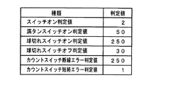
賞球処理において、CPU56は、入力判定値テーブルのオフセットとして「1」を設定し(ステップS150)、スイッチタイマのアドレスのオフセットとして「9」を設定する(ステップS151)。入力判定値テーブル(図32参照)のオフセット「1」は、入力判定値テーブルの2番目のデータ「50」を使用することを意味する。また、各スイッチタイマは、図15に示された入力ポートのビット順と同順に並んでいるので、スイッチタイマのアドレスのオフセット「9」は満タンスイッチ48に対応したスイッチタイマが指定されることを意味する。そして、スイッチオンチェックルーチンがコールされる(ステップS152)。
In the prize ball process, the
入力判定値テーブルとは、各スイッチについて、連続何回のオンが検出されたら確かにスイッチがオンしたと判定するための判定値が設定されているROM領域である。入力判定値テーブルの構成例は図32に示されている。図32に示すように、入力判定値テーブルには、上から順に、すなわちアドレス値が小さい領域から順に、「2」、「50」、「250」、「30」、「250」、「1」の判定値が設定されている。また、スイッチオンチェックルーチンでは、入力判定値テーブルの先頭アドレスとオフセット値とで決まるアドレスに設定されている判定値と、スイッチタイマの先頭アドレスとオフセット値とで決まるスイッチタイマの値とが比較され、一致した場合には、例えばスイッチオンフラグがセットされる。 The input determination value table is a ROM area in which a determination value for determining that the switch has been turned on when it is detected how many times it is continuously turned on is set for each switch. A configuration example of the input determination value table is shown in FIG. As shown in FIG. 32, the input determination value table includes “2”, “50”, “250”, “30”, “250”, “1” in order from the top, that is, in order from the smallest address value. The judgment value is set. In the switch-on check routine, the judgment value set at the address determined by the head address and the offset value in the input judgment value table is compared with the value of the switch timer determined by the head address and the offset value of the switch timer. If they match, for example, a switch-on flag is set.
スイッチオンチェックルーチンの一例が図31に示されている。スイッチオンチェックルーチンにおいて、満タンスイッチ48に対応するスイッチタイマの値が満タンスイッチオン判定値「50」に一致していればスイッチオンフラグがセットされるので(ステップS153)、満タンフラグがセットされる(ステップS154)。なお、図28には明示されていないが、満タンスイッチ48に対応したスイッチタイマの値が0になると、満タンフラグはリセットされる。
An example of a switch-on check routine is shown in FIG. In the switch-on check routine, if the value of the switch timer corresponding to the
また、CPU56は、入力判定値テーブルのオフセットとして「2」を設定し(ステップS156)、スイッチタイマのアドレスのオフセットとして「0A(H)」を設定する(ステップS157)。入力判定値テーブルのオフセット「2」は、入力判定値テーブルの3番目のデータ「250」を使用することを意味する。また、各スイッチタイマは、図14に示された入力ポートのビット順と同順に並んでいるので、スイッチタイマのアドレスのオフセット「0A(H)」は球切れスイッチ187に対応したスイッチタイマが指定されることを意味する。そして、スイッチオンチェックルーチンがコールされる(ステップS158)。
Further, the
スイッチオンチェックルーチンにおいて、球切れスイッチ187に対応するスイッチタイマの値が球切れスイッチオン判定値「250」に一致していればスイッチオンフラグがセットされるので(ステップS159)、球切れフラグがセットされる(ステップS160)。なお、図28には明示されていないが、球切れスイッチ187に対応したスイッチオフタイマが用意され、その値が50になると、球切れフラグはリセットされる。
In the switch-on check routine, if the value of the switch timer corresponding to the ball-
そして、CPU56は、払出停止状態であるか否か確認する(ステップS201)。払出停止状態は、払出制御基板37に対して払出を停止すべき状態であることを指示する払出制御コマンドである払出停止状態指定コマンドを送信した後の状態である。払出停止状態でなければ、上述した球切れ状態フラグまたは満タンフラグがオンになったか否かを確認する(ステップS202)。
Then, the
いずれかがオン状態に変化したときには、払出停止状態指定コマンドに関するコマンド送信テーブルをセットし(ステップS203)、コマンドセット処理をコールする(ステップS206)。ステップS203では、払出停止状態指定コマンドの払出制御コマンドが格納されているコマンド送信テーブル(ROM)の先頭アドレスが、コマンド送信テーブルのアドレスとして設定される。払出停止状態指定コマンドに関するコマンド送信テーブルには、後述するINTデータ、払出制御コマンドの1バイト目のデータ、および払出制御コマンドの2バイト目のデータが設定されている。なお、ステップS202において、いずれか一方のフラグが既にオン状態であったときに他方のフラグがオン状態になったときには、コマンド送信制御処理(ステップS203)は行われない。 When either of them changes to the on state, a command transmission table related to the payout stop state designation command is set (step S203), and command set processing is called (step S206). In step S203, the head address of the command transmission table (ROM) storing the payout control command of the payout stop state designation command is set as the address of the command transmission table. In the command transmission table relating to the payout stop state designation command, INT data described later, data of the first byte of the payout control command, and data of the second byte of the payout control command are set. In step S202, when one of the flags is already in the on state and the other flag is in the on state, the command transmission control process (step S203) is not performed.
また、払出停止状態であれば、球切れ状態フラグおよび満タンフラグがともにオフ状態になったか否かを確認する(ステップS204)。ともにオフ状態となったときには、払出可能状態指定コマンドに関するコマンド送信テーブルをセットし(ステップS205)、コマンドセット処理をコールする(ステップS207)。ステップS205では、払出可能状態指定コマンドの払出制御コマンドが格納されているコマンド送信テーブル(ROM)の先頭アドレスが、コマンド送信テーブルのアドレスとして設定される。払出可能状態指定コマンドに関するコマンド送信テーブルには、後述するINTデータ、払出制御コマンドの1バイト目のデータ、および払出制御コマンドの2バイト目のデータが設定されている。 If it is in the payout stop state, it is checked whether both the ball-out state flag and the full tank flag are turned off (step S204). When both are turned off, the command transmission table relating to the payable state designation command is set (step S205), and the command setting process is called (step S207). In step S205, the head address of the command transmission table (ROM) in which the payout control command of the payable state designation command is stored is set as the address of the command transmission table. In the command transmission table related to the payout enable state designation command, INT data, data of the first byte of the payout control command, and data of the second byte of the payout control command, which will be described later, are set.
さらに、CPU56は、入力判定値テーブルのオフセットとして「0」を設定し(ステップS221)、スイッチタイマのアドレスのオフセットとして「0」を設定する(ステップS222)。入力判定値テーブルのオフセット「0」は、入力判定値テーブルの最初のデータを使用することを意味する。また、各スイッチタイマは、図14に示された入力ポートのビット順と同順に並んでいるので、スイッチタイマのアドレスのオフセット「0」は入賞口スイッチ33aに対応したスイッチタイマが指定されることを意味する。また、繰り返し数として「4」をセットする(ステップS223)。そして、スイッチオンチェックルーチンがコールされる(ステップS224)。
Further, the
スイッチオンチェックルーチンにおいて、CPU56は、入力判定値テーブル(図32参照)の先頭アドレスを設定する(ステップS281)。そして、そのアドレスにオフセットを加算し(ステップS282)、加算後のアドレスからスイッチオン判定値をロードする(ステップS283)。
In the switch-on check routine, the
次いで、CPU56は、スイッチタイマの先頭アドレスを設定し(ステップS284)、そのアドレスにオフセットを加算し(ステップS285)、加算後のアドレスからスイッチタイマの値をロードする(ステップS286)。各スイッチタイマは、図14に示された入力ポートのビット順と同順に並んでいるので、スイッチに対応したスイッチタイマの値がロードされる。
Next, the
そして、CPU56は、ロードしたスイッチタイマの値とスイッチオン判定値とを比較する(ステップS287)。それらが一致すれば、スイッチオンフラグをセットする(ステップ128)。
Then, the
この場合には、スイッチオンチェックルーチンにおいて、入賞口スイッチ33aに対応するスイッチタイマの値がスイッチオン判定値「2」に一致していればスイッチオンフラグがセットされる(ステップS225)。そして、スイッチチェックオンルーチンは、スイッチタイマのアドレスのオフセットが更新されつつ(ステップS230)、最初に設定された繰り返し数分だけ実行されるので(ステップS228,S229)、結局、入賞口スイッチ33a,24a,29a,30aについて、対応するスイッチタイマの値がスイッチオン判定値「2」と比較されることになる。
In this case, in the switch-on check routine, the switch-on flag is set if the value of the switch timer corresponding to the winning
スイッチオンフラグがセットされたら、払い出すべき賞球個数としての「10」をリングバッファに設定する(ステップS226)。そして、総賞球数格納バッファの格納値に10を加算する(ステップS227)。なお、リングバッファにデータを書き込んだときには、書込ポインタをインクリメントし、リングバッファの最後の領域にデータを書き込まれたときには、書込ポインタを、リングバッファの最初の領域を指すように更新する。 When the switch-on flag is set, “10” as the number of prize balls to be paid out is set in the ring buffer (step S226). Then, 10 is added to the stored value of the total winning ball number storage buffer (step S227). When data is written to the ring buffer, the write pointer is incremented. When data is written to the last area of the ring buffer, the write pointer is updated to point to the first area of the ring buffer.
総賞球数格納バッファは、払出制御手段に対して指示した賞球個数の累積値(ただし、払い出しがなされると減算される)が格納されるバッファであり、バックアップRAMに形成されている。なお、この実施の形態では、リングバッファにデータを書き込んだ時点で総賞球数格納バッファの格納値に対する加算処理が行われるが、払い出すべき賞球個数を指示する払出制御コマンドを出力ポートに出力した時点で総賞球数格納バッファの格納値に対する、出力する払出制御コマンドに対応した賞球数の加算処理を行ってもよい。 The total winning ball number storage buffer is a buffer for storing a cumulative value of the number of winning balls instructed to the payout control means (however, subtracted when paying out), and is formed in the backup RAM. In this embodiment, when data is written to the ring buffer, an addition process is performed on the stored value of the total prize ball number storage buffer, but a payout control command for instructing the number of prize balls to be paid out is output to the output port. At the time of output, the number of prize balls corresponding to the payout control command to be output may be added to the value stored in the total prize ball number storage buffer.
次に、CPU56は、入力判定値テーブルのオフセットとして「0」を設定し(ステップS231)、スイッチタイマのアドレスのオフセットとして「4」を設定する(ステップS232)。入力判定値テーブルのオフセット「0」は、入力判定値テーブルの最初のデータを使用することを意味する。また、各スイッチタイマは、図14に示された入力ポートのビット順と同順に並んでいるので、スイッチタイマのアドレスのオフセット「4」は始動口スイッチ14aに対応したスイッチタイマが指定されることを意味する。そして、スイッチオンチェックルーチンがコールされる(ステップS233)。
Next, the
スイッチオンチェックルーチンにおいて、始動口スイッチ14aに対応するスイッチタイマの値がスイッチオン判定値「2」に一致していればスイッチオンフラグがセットされる(ステップS234)。スイッチオンフラグがセットされたら、払い出すべき賞球個数としての「6」をリングバッファに設定する(ステップS235)。また、総賞球数格納バッファの格納値に6を加算する(ステップS236)。 In the switch-on check routine, if the value of the switch timer corresponding to the start port switch 14a matches the switch-on determination value “2”, the switch-on flag is set (step S234). When the switch-on flag is set, “6” as the number of prize balls to be paid out is set in the ring buffer (step S235). Further, 6 is added to the stored value of the total winning ball number storage buffer (step S236).
次いで、CPU56は、入力判定値テーブルのオフセットとして「0」を設定し(ステップS241)、スイッチタイマのアドレスのオフセットとして「5」を設定する(ステップS242)。入力判定値テーブルのオフセット「0」は、入力判定値テーブルの最初のデータを使用することを意味する。また、各スイッチタイマは、図15に示された入力ポートのビット順と同順に並んでいるので、スイッチタイマのアドレスのオフセット「5」はカウントスイッチ23に対応したスイッチタイマが指定されることを意味する。そして、スイッチオンチェックルーチンがコールされる(ステップS243)。
Next, the
スイッチオンチェックルーチンにおいて、カウントスイッチ23に対応するスイッチタイマの値がスイッチオン判定値「2」に一致していればスイッチオンフラグがセットされる(ステップS244)。スイッチオンフラグがセットされたら、払い出すべき賞球個数としての「15」をリングバッファに設定する(ステップS245)。また、総賞球数格納バッファの格納値に15を加算する(ステップS246)。
In the switch-on check routine, if the value of the switch timer corresponding to the
そして、リングバッファにデータが存在する場合には(ステップS247)、読出ポインタが指すリングバッファの内容を送信バッファにセットするとともに(ステップS248)、読出ポインタの値を更新(リングバッファの次の領域を指すように更新)し(ステップS249)、賞球個数に関するコマンド送信テーブルをセットし(ステップS250)、コマンドセット処理をコールする(ステップS251)。コマンドセット処理の動作については後で詳しく説明する。 If data exists in the ring buffer (step S247), the contents of the ring buffer pointed to by the read pointer are set in the transmission buffer (step S248), and the value of the read pointer is updated (next area of the ring buffer). (Step S249), a command transmission table relating to the number of winning balls is set (Step S250), and command set processing is called (Step S251). The operation of the command set process will be described in detail later.
ステップS250では、賞球個数に関する払出制御コマンドが格納されているコマンド送信テーブル(ROM)の先頭アドレスが、コマンド送信テーブルのアドレスとして設定される。賞球個数に関するコマンド送信テーブルには、後述するINTデータ(01(H))、払出制御コマンドの1バイト目のデータ(F0(H))、および払出制御コマンドの2バイト目のデータが設定されている。ただし、2バイト目のデータとして「80(H)」が設定されている。 In step S250, the head address of the command transmission table (ROM) in which the payout control command relating to the number of winning balls is stored is set as the address of the command transmission table. In the command transmission table relating to the number of winning balls, INT data (01 (H)) described later, data of the first byte of the payout control command (F0 (H)), and data of the second byte of the payout control command are set. ing. However, “80 (H)” is set as the second byte data.
以上のように、遊技制御手段から払出制御基板37に賞球個数を指示する払出制御コマンドを出力しようとするときに、賞球個数に関するコマンド送信テーブルのアドレス設定と送信バッファの設定とが行われる。そして、コマンドセット処理によって、賞球個数に関するコマンド送信テーブルと送信バッファの設定内容とにもとづいて払出制御コマンドが払出制御基板37に送信される。なお、ステップS247において、書込ポインタと読出ポインタとの差によってデータがあるか否か確認することができるが、リングバッファ内の未処理のデータ個数を示すカウンタを設け、カウント値によってデータがあるか否か確認するようにしてもよい。
As described above, when the game control means tries to output a payout control command for instructing the number of prize balls to the
そして、総賞球数格納バッファの内容が0でない場合、すなわち、まだ賞球残がある場合には、CPU56は、賞球払出中フラグをオンする(ステップS252,S253)。
Then, when the content of the total prize ball number storage buffer is not 0, that is, when there is still a prize ball remaining, the
また、CPU56は、賞球払出中フラグがオンしているときには(ステップS254)、球払出装置97から実際に払い出された賞球個数を監視して総賞球数格納バッファの格納値を減算する賞球個数減算処理を行う(ステップS255)。なお、賞球払出中フラグがオンからオフに変化したときには、ランプ制御基板35に対して、賞球ランプ51の点灯を指示するランプ制御コマンドが送信される。
Further, when the winning ball payout flag is on (step S254), the
以上に説明したように、この実施の形態では、払い出される遊技球の不足が検知されたとき(球切れ時)にも、下皿満タンで遊技球を払い出すべきでないときにも、同一のコマンドである払出停止状態指定コマンドが遊技制御手段から払出制御手段に通知される(図28参照)。すなわち、払出停止をすべき条件が異なっていても、共通のコマンドが遊技制御手段から払出制御手段に送信される。換言すれば、遊技媒体の払出の完了とは異なる複数の払出停止条件のうち、いずれの条件が成立したときでも共通の制御コマンドによって払出制御手段に対して払出が可能な状態でないことが指令される。そして、払出制御手段は、払出停止状態指定コマンドを受信すると遊技球の払出を停止する。 As described above, in this embodiment, even when a shortage of game balls to be paid out is detected (at the time of running out of balls), even when the game balls should not be paid out when the lower plate is full, A payout stop state designation command as a command is notified from the game control means to the payout control means (see FIG. 28). That is, even if the conditions for stopping payout are different, a common command is transmitted from the game control means to the payout control means. In other words, it is instructed that the payout control means is not in a state where payout is not possible by a common control command even when any of the plurality of payout stop conditions different from the completion of payout of the game medium is satisfied. The When the payout control means receives the payout stop state designation command, the payout control means stops paying out the game balls.
いずれの払出停止条件が成立したときでも共通の制御コマンドによって払出制御手段に対して払出が可能な状態でないことを指令できるので、遊技制御手段から払出制御手段に対する情報伝達に関する負荷が低減される。その結果、遊技制御手段におけるプログラム容量が節減されて遊技制御に回せるプログラム容量が増える等の利点が生ずる。 Even when any payout stop condition is satisfied, a common control command can be used to instruct that the payout control means is not in a payable state, so that a load related to information transmission from the game control means to the payout control means is reduced. As a result, there is an advantage that the program capacity in the game control means is reduced and the program capacity that can be used for game control is increased.
なお、後述するように、払出制御手段は、払出停止状態指定コマンドを受信すると、賞球としての球払出と球貸しとしての球払出とをともに停止させる。また、払出可能状態指定コマンドを受信すると、、賞球としての球払出と球貸しとしての球払出とをともに可能な状態とする。しかし、遊技制御手段から払出制御手段に対して、賞球としての球払出を停止または再開させる払出制御コマンドと、球貸しとしての球払出を停止または再開させる払出制御コマンドとを、別の制御コマンドとして送信するようにしてもよい。 As will be described later, when the payout control means receives the payout stop state designation command, it stops both the ball payout as the winning ball and the ball payout as the ball lending. In addition, when a payout enabled state designation command is received, a ball payout as a winning ball and a ball payout as a ball lending are both enabled. However, the game control means gives the payout control means a separate payout control command for stopping or restarting the payout of the ball as a prize ball, and a payout control command for stopping or restarting the payout of the ball as a ball rental. May be transmitted.
また、この実施の形態では、払出停止中であっても(ステップS201,S204)、ステップS221〜S251の処理が実行される。すなわち、遊技制御手段は、払出停止状態であっても、賞球個数を指示するための払出制御コマンドを送信することができる。すなわち、賞球個数を指示するためのコマンドが、払出停止状態であっても払出制御手段に伝達され、払出停止状態が解除されたときに、早めに賞球払出を開始することができる。また、遊技制御手段において、払出停止状態における入賞にもとづく賞球個数を記憶するための大きな記憶領域は必要とされない。 In this embodiment, even if the payout is stopped (steps S201 and S204), the processing of steps S221 to S251 is executed. That is, the game control means can transmit a payout control command for instructing the number of winning balls even when the payout is stopped. That is, a command for instructing the number of prize balls is transmitted to the payout control means even in the payout stop state, and when the payout stop state is canceled, the payout of the prize balls can be started early. Further, the game control means does not require a large storage area for storing the number of winning balls based on winning in the payout stop state.
次に、遊技制御手段から各電気部品制御手段に対する制御コマンドの送信方式について説明しておく。遊技制御手段から他の電気部品制御基板(サブ基板)に制御コマンドを出力しようとするときに、コマンド送信テーブルの先頭アドレスの設定が行われる。図33(A)は、コマンド送信テーブルの一構成例を示す説明図である。1つのコマンド送信テーブルは3バイトで構成され、1バイト目にはINTデータが設定される。また、2バイト目のコマンドデータ1には、制御コマンドの1バイト目のMODEデータが設定される。そして、3バイト目のコマンドデータ2には、制御コマンドの2バイト目のEXTデータが設定される。
Next, a transmission method of control commands from the game control means to each electric component control means will be described. When a control command is to be output from the game control means to another electrical component control board (sub board), the head address of the command transmission table is set. FIG. 33A is an explanatory diagram showing a configuration example of the command transmission table. One command transmission table is composed of 3 bytes, and INT data is set in the first byte. In the
なお、EXTデータそのものがコマンドデータ2の領域に設定されてもよいが、コマンドデータ2には、EXTデータが格納されているテーブルのアドレスを指定するためのデータが設定されるようにしてもよい。例えば、コマンドデータ2のビット7(ワークエリア参照ビット)が0であれば、コマンドデータ2にEXTデータそのものが設定されていることを示す。また、コマンドデータ2のビット7(ワークエリア参照ビット)が1であれば、所定のアドレステーブル(コマンド拡張データアドレステーブル)内のアドレスが指す領域に格納されているデータがEXTデータとして使用されることを示す。例えば、払出制御コマンドの場合には、ワークエリア参照ビットが1であり、EXTデータとして、送信バッファの内容が使用される。
Although the EXT data itself may be set in the area of the
図33(B)INTデータの一構成例を示す説明図である。INTデータにおけるビット0は、払出制御基板37に払出制御コマンドを送信すべきか否かを示す。ビット0が「1」であるならば、払出制御コマンドを送信すべきことを示す。
FIG. 33 (B) is an explanatory diagram showing a configuration example of INT data.
この実施の形態では、各電気部品制御主基板に送信される各制御コマンドについて、それぞれコマンド送信テーブルが用意され、制御コマンドを送信する前に、使用すべきコマンド送信テーブルのアドレスが設定される。また、複数のコマンド送信テーブルを1つのテーブルとして用意してもよい。例えば、図33(C)に示すように、複数の制御コマンドを格納することが可能な複数のコマンド送信テーブルを含む1個のテーブルが用意する。その場合、CPU56は、例えば、表示制御コマンド制御処理において、ポインタが差しているコマンド送信テーブルから、INTデータ、コマンドデータ1およびコマンドデータ2を設定し、表示制御コマンドを送信する。そして、ポインタを更新する。その後、ポインタが指定するコマンド送信テーブルが終了コードを示すまで、表示制御コマンドの送信処理を繰り返す。
In this embodiment, a command transmission table is prepared for each control command transmitted to each electric component control main board, and the address of the command transmission table to be used is set before transmitting the control command. A plurality of command transmission tables may be prepared as one table. For example, as shown in FIG. 33C, one table including a plurality of command transmission tables capable of storing a plurality of control commands is prepared. In that case, for example, in the display control command control process, the
図34は、コマンドセット処理の処理例を示すフローチャートである。コマンドセット処理は、コマンド出力処理とINT信号出力処理とを含む処理である。コマンドセット処理において、CPU56は、まず、コマンド送信テーブルのアドレスをスタック等に退避する(ステップS331)。そして、ポインタが指していたコマンド送信テーブルのINTデータを引数1にロードする(ステップS332)。引数1は、後述するコマンド送信処理に対する入力情報になる。また、コマンド送信テーブルを指すアドレスを+1する(ステップS333)。従って、コマンド送信テーブルを指すアドレスは、コマンドデータ1のアドレスに一致する。
FIG. 34 is a flowchart illustrating an example of command set processing. The command set process is a process including a command output process and an INT signal output process. In the command set process, the
次いで、CPU56は、コマンドデータ1を読み出して引数2に設定する(ステップS334)。引数2も、後述するコマンド送信処理に対する入力情報になる。そして、コマンド送信処理ルーチンをコールする(ステップS335)。
Next, the
図35は、コマンド送信処理ルーチンを示すフローチャートである。コマンド送信処理ルーチンにおいて、CPU56は、まず、引数1に設定されているデータすなわちINTデータを、比較値として決められているワークエリアに設定する(ステップS351)。次いで、送信回数=4を、処理数として決められているワークエリアに設定する(ステップS352)。そして、ポート1のアドレスをIOアドレスにセットする(ステップS353)。この実施の形態では、ポート1のアドレスは払出制御コマンドデータを出力するための出力ポートのアドレスであり、ポート2〜4のアドレスが、表示制御コマンド、ランプ制御コマンドデータ、音制御コマンドデータを出力するための出力ポートのアドレスである。
FIG. 35 is a flowchart showing a command transmission processing routine. In the command transmission processing routine, the
次に、CPU56は、比較値を1ビット右にシフトする(ステップS354)。シフト処理の結果、キャリービットが1になったか否か確認する(ステップS355)。キャリービットが1になったということは、INTデータにおける最も右側のビットが「1」であったことを意味する。この実施の形態では4回のシフト処理が行われるのであるが、例えば、表示制御コマンドを送信すべきことが指定されているときには、2回目のシフト処理でキャリービットが1になる。
Next, the
キャリービットが1になった場合には、引数2に設定されているデータ、この場合にはコマンドデータ1(すなわちMODEデータ)を、IOアドレスとして設定されているアドレスに出力する(ステップS356)。2回目のシフト処理が行われたときにはIOアドレスにポート2のアドレスが設定されているので、そのときに、表示制御コマンドのMODEデータがポート2に出力される。
When the carry bit becomes 1, the data set in the
次いで、CPU56は、IOアドレスを1加算するとともに(ステップS357)、処理数を1減算する(ステップS358)。加算前にポート2を示していた場合には、IOアドレスに対する加算処理によって、IOアドレスにはポート3のアドレスが設定される。ポート3は、ランプ制御コマンドを出力するためのポートである。そして、CPU56は、処理数の値を確認し(ステップS359)、値が0になっていなければ、ステップS354に戻る。ステップS354で再度シフト処理が行われる。
Next, the
2回目のシフト処理ではINTデータにおけるビット1の値が押し出され、ビット1の値に応じてキャリーフラグが「1」または「0」になる。従って、表示制御コマンドを送信すべきことが指定されているか否かのチェックが行われる。同様に、3回目および4回目のシフト処理によって、ランプ制御コマンドおよび音制御コマンドを送信すべきことが指定されているか否かのチェックが行われる。このように、それぞれのシフト処理が行われるときに、IOアドレスには、シフト処理によってチェックされるコマンド(払出制御コマンド、表示制御コマンド、ランプ制御コマンド、音制御コマンド)に対応したIOアドレスが設定されている。
In the second shift process, the value of
よって、キャリーフラグが「1」になったときには、対応する出力ポート(ポート1〜ポート4)に制御コマンドが送信される。すなわち、1つの共通モジュールで、各電気部品制御手段に対するコマンドの送信処理(出力処理)を行うことができる。
Therefore, when the carry flag becomes “1”, the control command is transmitted to the corresponding output port (
また、このように、シフト処理のみによってどの電気部品制御手段に対して制御コマンドを出力すべきかが判定されるので、いずれの電気部品制御手段に対して制御コマンドを出力すべきか判定する処理が簡略化されている。 Further, since it is determined to which electrical component control means the control command should be output only by the shift process, the process for determining to which electrical component control means the control command should be output is simplified. It has become.
次に、CPU56は、シフト処理開始前のINTデータが格納されている引数1の内容を読み出し(ステップS360)、読み出したデータをポート0に出力する(ステップS361)。この実施の形態では、ポート0のアドレスは、各制御信号についてのINT信号を出力するためのポートであり、ポート0のビット0〜4が、それぞれ、払出制御INT信号、表示制御INT信号、ランプ制御INT信号、音制御INT信号を出力するためのポートである。INTデータでは、ステップS351〜S359の処理で出力された制御コマンド(払出制御コマンド、表示制御コマンド、ランプ制御コマンド、音制御コマンド)に応じたINT信号の出力ビットに対応したビットが「1」になっている。従って、ポート1〜ポート4のいずれかに出力された制御コマンド(払出制御コマンド、表示制御コマンド、ランプ制御コマンド、音制御コマンド)に対応したINT信号がオフ状態(ローレベル)になる。
Next, the
次いで、CPU56は、ウェイトカウンタに所定値を設定し(ステップS362)、その値が0になるまで1ずつ減算する(ステップS363,S364)。ウェイトカウンタの値が0になると、クリアデータ(00)を設定して(ステップS365)、そのデータをポート0に出力する(ステップS366)。よって、INT信号はオフ状態になる。そして、ウェイトカウンタに所定値を設定し(ステップS362)、その値が0になるまで1ずつ減算する(ステップS368,S369)。
Next, the
以上のようにして、制御コマンドの1バイト目のMODEデータが送信される。そこで、CPU56は、図34に示すステップS336で、コマンド送信テーブルを指す値を1加算する。従って、3バイト目のコマンドデータ2の領域が指定される。CPU56は、指し示されたコマンドデータ2の内容を引数2にロードする(ステップS337)。また、コマンドデータ2のビット7(ワークエリア参照ビット)の値が「0」であるか否か確認する(ステップS338)。0でなければ、コマンド拡張データアドレステーブルの先頭アドレスをポインタにセットし(ステップS339)、そのポインタにコマンドデータ2のビット6〜ビット0の値を加算してアドレスを算出する(ステップS340)。そして、そのアドレスが指すエリアのデータを引数2にロードする(ステップS341)。
As described above, the MODE data of the first byte of the control command is transmitted. Therefore, the
コマンド拡張データアドレステーブルには、電気部品制御手段に送信されうるEXTデータが順次設定されている。よって、以上の処理によって、ワークエリア参照ビットの値が「1」であれば、コマンドデータ2の内容に応じたコマンド拡張データアドレステーブル内のEXTデータが引数2にロードされ、ワークエリア参照ビットの値が「0」であれば、コマンドデータ2の内容がそのまま引数2にロードされる。なお、コマンド拡張データアドレステーブルからEXTデータが読み出される場合でも、そのデータのビット7は「0」である。
In the command extended data address table, EXT data that can be transmitted to the electrical component control means is sequentially set. Therefore, if the value of the work area reference bit is “1” by the above processing, the EXT data in the command extended data address table corresponding to the contents of the
次に、CPU56は、コマンド送信処理ルーチンをコールする(ステップS342)。従って、MODEデータの送信の場合と同様のタイミングでEXTデータが送信される。その後、CPU56は、コマンド送信テーブルのアドレスを復帰し(ステップS343)、コマンド送信テーブルを指す読出ポインタの値を更新する(ステップS344)。そして、さらに送信すべきコマンドがあれば(ステップS345)、ステップS331に戻る。
Next, the
以上のようにして、2バイト構成の制御コマンド(払出制御コマンド、表示制御コマンド、ランプ制御コマンド、音制御コマンド)が、対応する電気部品制御手段に送信される。電気部品制御手段ではINT信号のレベル変化を検出すると制御コマンドの取り込み処理を開始するのであるが、いずれの電気部品制御手段についても、取り込み処理が完了する前に遊技制御手段からの新たな信号が信号線に出力されることはない。すなわち、表示制御手段等の各電気部品制御手段において、確実なコマンド受信処理が行われる。なお、INT信号の極性を図20に示された場合と逆にしてもよい。 As described above, the control command (payout control command, display control command, lamp control command, sound control command) having a 2-byte configuration is transmitted to the corresponding electrical component control means. When the level change of the INT signal is detected in the electrical component control means, the control command capturing process is started. However, any electrical component control means receives a new signal from the game control means before the capturing process is completed. It is not output to the signal line. That is, reliable command reception processing is performed in each electrical component control means such as a display control means. The polarity of the INT signal may be reversed from that shown in FIG.
以上のように、コマンドセット処理は、表示制御コマンド、ランプ制御コマンド、音制御コマンドおよび払出制御コマンドのいずれの制御コマンドを送信する際にも使用される共通モジュールである。従って、遊技制御手段が実行する遊技制御プログラムのプログラム容量を節減することができる。 As described above, the command set process is a common module used when transmitting any of the display control commands, lamp control commands, sound control commands, and payout control commands. Therefore, the program capacity of the game control program executed by the game control means can be saved.
さらに、表示制御コマンド、ランプ制御コマンド、音制御コマンドおよび払出制御コマンドの形態が共通しているので、各制御コマンドを作成する処理も容易にモジュール化することができる。この実施の形態では、各制御コマンドのそれぞれについてのコマンド送信テーブル(図33(A)参照)があらかじめROMに設定されていたが、各制御コマンドを送信する際に作成することもできる。例えば、図33(A)に示されたようなコマンド送信テーブルをRAMに作成した後に、図34に示されたコマンドセット処理を呼び出せばよい。 Furthermore, since the forms of the display control command, the lamp control command, the sound control command, and the payout control command are common, the process of creating each control command can be easily modularized. In this embodiment, the command transmission table (see FIG. 33A) for each control command is set in the ROM in advance, but can be created when each control command is transmitted. For example, after creating a command transmission table as shown in FIG. 33A in the RAM, the command set process shown in FIG. 34 may be called.
表示制御コマンド、ランプ制御コマンド、音制御コマンドおよび払出制御コマンドのいずれの制御コマンドについてのコマンド送信テーブルも、INTデータ、コマンドデータ1,2で構成されているので、制御コマンドを作成する共通モジュールとして、いずれかのビットが「1」になっているINTデータと、コマンドデータ1,2に設定されるべきデータとを入力データとして共通モジュールを呼び出せば、いずれの制御コマンドについても図33に示されたようなコマンド送信テーブルが作成されるように、制御コマンドを作成する共通モジュールを構成することができる。
Since the command transmission table for any of the display control commands, lamp control commands, sound control commands, and payout control commands is composed of INT data and
次に、電気部品制御手段の一例として表示制御手段(表示制御用CPU101およびその周辺回路)の動作について説明する。図36は、表示制御手段が実行するメイン処理を示すフローチャートである。表示制御用CPU101は、メイン処理において、まず、レジスタ、ワークエリアを含むRAMおよび出力ポート等を初期化する初期化処理を実行する(ステップS401)。次いで、乱数を生成するためのカウンタ値を更新する処理を行う(ステップS402)。そして、主基板31から表示制御コマンドを受信したか否かの確認を行う(ステップS403:コマンド確認処理)。また、受信した表示制御コマンドに応じて、使用するプロセスデータ(表示制御を進行させるためのタイマや表示内容が設定されているデータ)を変更する等の処理であるコマンド実行処理を行う(ステップS404)。なお、主基板31からの表示制御コマンドは、INT信号の入力に応じて起動される割込処理で取り込まれ、RAMに形成されている受信コマンドバッファに格納される。
Next, the operation of display control means (display control CPU 101 and its peripheral circuits) will be described as an example of electrical component control means. FIG. 36 is a flowchart showing main processing executed by the display control means. In the main process, the display control CPU 101 first executes an initialization process for initializing a register, a RAM including a work area, an output port, and the like (step S401). Next, a process for updating a counter value for generating a random number is performed (step S402). Then, it is confirmed whether or not a display control command has been received from the main board 31 (step S403: command confirmation processing). Further, a command execution process, such as a process for changing process data to be used (data for setting a timer for progressing display control or display contents), is performed according to the received display control command (step S404). ). The display control command from the
その後、この実施の形態では、表示制御用CPU101は、タイマ割込フラグの監視(ステップS405)を行う。そして、図37に示すように、タイマ割込が発生すると、表示制御用CPU101は、タイマ割込フラグをセットする(ステップS411)。メイン処理において、タイマ割込フラグがセットされていたら、表示制御用CPU101は、そのフラグをクリアするとともに、表示制御プロセス処理およびポート出力処理を行う(ステップS406,S407)。 Thereafter, in this embodiment, the display control CPU 101 monitors the timer interrupt flag (step S405). Then, as shown in FIG. 37, when a timer interrupt occurs, the display control CPU 101 sets a timer interrupt flag (step S411). If the timer interrupt flag is set in the main processing, the display control CPU 101 clears the flag and performs display control process processing and port output processing (steps S406 and S407).
次に、主基板31からの表示制御コマンド受信処理について説明する。図38は、主基板31から受信した表示制御コマンドを格納するためのコマンド受信バッファの一構成例を示す説明図である。この例では、2バイト構成の表示制御コマンドを6個格納可能なリングバッファ形式のコマンド受信バッファが用いられる。従って、コマンド受信バッファは、受信コマンドバッファ1〜12の12バイトの領域で構成される。そして、受信したコマンドをどの領域に格納するのかを示すコマンド受信個数カウンタが用いられる。コマンド受信個数カウンタは、0〜11の値をとる。
Next, display control command reception processing from the
図39は、割込処理による表示制御コマンド受信処理を示すフローチャートである。主基板31からの表示制御用のINT信号は表示制御用CPU101の割込端子に入力されている。例えば、主基板31からのINT信号のレベルが変化すると、表示制御用CPU101において割込がかかる。そして、図39に示す表示制御コマンドの受信処理が開始される。
FIG. 39 is a flowchart showing display control command reception processing by interrupt processing. An INT signal for display control from the
なお、取込信号としてのパルス状(矩形波状)のINT信号のレベル変化タイミング(エッジ)で割込が発生するように構成すれば、エッジは立ち上がりエッジであっても立ち下がりエッジであってもよい。いずれにせよ、取込信号としてのパルス状(矩形波状)のINT信号のレベル変化タイミング(エッジ)で割込が発生するように構成される。このようにすることで、コマンドの取込が指示された段階でいち早くコマンド受信を行うことが可能になる。また、Aの期間(図35)が経過するまでINT信号の出力が待機されるので、INT信号の出力時に、制御信号CD0〜CD7のライン上のコマンドデータの出力状態は安定している。よって、表示制御手段において、表示制御コマンドは良好に受信される。 If the interrupt is generated at the level change timing (edge) of the pulsed (rectangular wave) INT signal as the capture signal, the edge may be a rising edge or a falling edge. Good. In any case, the interrupt is generated at the level change timing (edge) of the pulsed (rectangular wave) INT signal as the capture signal. By doing so, it becomes possible to receive a command promptly at the stage where command fetch is instructed. Since the output of the INT signal is on standby until the period A (FIG. 35) elapses, the output state of the command data on the lines of the control signals CD0 to CD7 is stable when the INT signal is output. Therefore, the display control command is favorably received by the display control means.
表示制御コマンドの受信処理において、表示制御用CPU101は、まず、各レジスタをスタックに退避する(ステップS670)。なお、割込が発生すると表示制御用CPU101は自動的に割込禁止状態に設定するが、自動的に割込禁止状態にならないCPUを用いている場合には、ステップS670の処理の実行前に割込禁止命令(DI命令)を発行することが好ましい。次いで、表示制御コマンドデータの入力に割り当てられている入力ポートからデータを読み込む(ステップS671)。そして、2バイト構成の表示制御コマンドのうちの1バイト目であるか否か確認する(ステップS672)。 In the display control command reception process, the display control CPU 101 first saves each register to the stack (step S670). When an interrupt occurs, the display control CPU 101 automatically sets the interrupt prohibited state. However, if a CPU that does not automatically enter the interrupt prohibited state is used, before executing the process of step S670. It is preferable to issue an interrupt prohibition instruction (DI instruction). Next, data is read from an input port assigned to input of display control command data (step S671). And it is confirmed whether it is the 1st byte of the display control command of 2 bytes composition (Step S672).
1バイト目であるか否かは、受信したコマンドの先頭ビットが「1」であるか否かによって確認される。先頭ビットが「1」であるのは、2バイト構成である表示制御コマンドのうちのMODEデータ(1バイト目)のはずである(図19参照)。そこで、表示制御用CPU101は、先頭ビットが「1」であれば、有効な1バイト目を受信したとして、受信したコマンドを受信バッファ領域におけるコマンド受信個数カウンタが示す受信コマンドバッファに格納する(ステップS673)。 Whether or not it is the first byte is confirmed by whether or not the first bit of the received command is “1”. The first bit is “1”, which should be MODE data (first byte) in the display control command having a 2-byte configuration (see FIG. 19). Therefore, if the first bit is “1”, the display control CPU 101 stores the received command in the reception command buffer indicated by the command reception number counter in the reception buffer area, assuming that the first valid byte has been received (step S1). S673).
表示制御コマンドのうちの1バイト目でなければ、1バイト目を既に受信したか否か確認する(ステップS674)。既に受信したか否かは、受信バッファ(受信コマンドバッファ)に有効なデータが設定されているか否かによって確認される。 If it is not the first byte of the display control command, it is confirmed whether or not the first byte has already been received (step S674). Whether or not it has already been received is confirmed by whether or not valid data is set in the reception buffer (reception command buffer).
1バイト目を既に受信している場合には、受信した1バイトのうちの先頭ビットが「0」であるか否か確認する。そして、先頭ビットが「0」であれば、有効な2バイト目を受信したとして、受信したコマンドを、受信バッファ領域におけるコマンド受信個数カウンタ+1が示す受信コマンドバッファに格納する(ステップS675)。先頭ビットが「0」であるのは、2バイト構成である表示制御コマンドのうちのEXTデータ(2バイト目)のはずである(図19参照)。なお、ステップS674における確認結果が1バイト目を既に受信したである場合には、2バイト目として受信したデータのうちの先頭ビットが「0」でなければ処理を終了する。 If the first byte has already been received, it is confirmed whether or not the first bit of the received 1 byte is “0”. If the first bit is “0”, it is determined that a valid second byte has been received, and the received command is stored in the reception command buffer indicated by the command reception number counter + 1 in the reception buffer area (step S675). The first bit of “0” is supposed to be EXT data (second byte) in the display control command having a 2-byte configuration (see FIG. 19). If the confirmation result in step S674 indicates that the first byte has already been received, the process ends unless the first bit of the data received as the second byte is “0”.
ステップS675において、2バイト目のコマンドデータを格納すると、コマンド受信個数カウンタに2を加算する(ステップS676)。そして、コマンド受信カウンタが12以上であるか否か確認し(ステップS677)、12以上であればコマンド受信個数カウンタをクリアする(ステップS678)。その後、退避されていたレジスタを復帰し(ステップS679)、割込許可に設定する(ステップS680)。 In step S675, when the command data of the second byte is stored, 2 is added to the command reception number counter (step S676). Then, it is confirmed whether or not the command reception counter is 12 or more (step S677), and if it is 12 or more, the command reception number counter is cleared (step S678). Thereafter, the saved register is restored (step S679), and interrupt permission is set (step S680).
表示制御コマンドは2バイト構成であって、1バイト目(MODE)と2バイト目(EXT)とは、受信側で直ちに区別可能に構成されている。すなわち、先頭ビットによって、MODEとしてのデータを受信したのかEXTとしてのデータを受信したのかを、受信側において直ちに検出できる。よって、上述したように、適正なデータを受信したのか否かを容易に判定することができる。 The display control command has a two-byte configuration, and the first byte (MODE) and the second byte (EXT) are configured to be immediately distinguishable on the receiving side. In other words, the reception side can immediately detect whether the data as MODE or the data as EXT has been received by the first bit. Therefore, as described above, it can be easily determined whether or not appropriate data has been received.
このように、図柄制御基板80には、受信した表示制御コマンドを同時の複数個格納することが可能な格納エリアとしての受信バッファ領域が設けられ、受信バッファ領域における受信コマンドバッファに表示制御コマンドが格納されると、格納アドレスに相当するコマンド受信個数カウンタが更新される。また、受信バッファ領域における最後の受信コマンドバッファに表示制御コマンドが格納されると、コマンド受信個数カウンタの値が0に戻される。すなわち、格納アドレスが受信バッファ領域の先頭アドレスを指すように設定される。
As described above, the
なお、表示制御用CPU101は、受信バッファ領域における読出アドレスにもとづいて受信バッファ領域内の表示制御コマンドを読み出す。そして、1個の表示制御コマンドを読み出すと読出アドレスを更新する。すなわち、次の受信コマンドバッファを指すように更新される。例えば、上述したメイン処理におけるコマンド認識処理において、受信バッファ領域に表示制御コマンドが格納されていることが検出されると、コマンド実行処理において、読み出された表示制御コマンドで指示される表示制御処理を開始する。従って、表示制御手段は、受信した順番に従って読出アドレスで指示される特定の受信コマンドバッファから表示制御コマンドを読み出し、読み出した表示制御コマンドに応じた表示制御処理を開始する。 The display control CPU 101 reads the display control command in the reception buffer area based on the read address in the reception buffer area. When one display control command is read, the read address is updated. That is, it is updated to point to the next received command buffer. For example, in the command recognition process in the main process described above, when it is detected that a display control command is stored in the reception buffer area, the display control process instructed by the read display control command in the command execution process To start. Therefore, the display control means reads the display control command from the specific reception command buffer indicated by the read address according to the reception order, and starts the display control process corresponding to the read display control command.
以上のようにして、表示制御手段は、主基板31から送信された表示制御コマンドを受信し、受信した表示制御コマンドに応じた表示制御処理を行うことができる。なお、ここでは、電気部品制御手段の一例として表示制御手段を例にしたが、ランプ制御手段や音制御手段が主基板31からの制御コマンドを受信する場合も、表示制御手段の場合と同様の制御によって受信することができる。
As described above, the display control means can receive the display control command transmitted from the
次に、電気部品制御手段の他の例である払出制御手段(払出制御用CPU371およびROM,RAM等の周辺回路)の動作を説明する。図40は、この実施の形態における出力ポートの割り当てを示す説明図である。図40に示すように、出力ポートC(アドレス00H)は、払出モータ289に出力される駆動信号等の出力ポートである。また、出力ポートD(アドレス01H)は、7セグメントLEDであるエラー表示LED374に出力される表示制御信号の出力ポートである。そして、出力ポートE(アドレス02H)は、振分ソレノイド310に出力される駆動信号、およびカードユニット50に対するEXS信号とPRDY信号とを出力するための出力ポートである。
Next, the operation of payout control means (payout control CPU 371 and peripheral circuits such as ROM and RAM), which is another example of the electrical component control means, will be described. FIG. 40 is an explanatory diagram showing assignment of output ports in this embodiment. As shown in FIG. 40, the output port C (
図41は、この実施の形態における入力ポートのビット割り当てを示す説明図である。図41に示すように、入力ポートA(アドレス06H)は、主基板31から送信された払出制御コマンドの8ビットの払出制御信号を取り込むための入力ポートである。また、入力ポートB(アドレス07H)のビット0〜1には、それぞれ、賞球カウントスイッチ301Aおよび球貸しカウントスイッチ301Bの検出信号が入力される。ビット2〜5には、カードユニット50からのBRDY信号、BRQ信号、VL信号およびクリアスイッチ921の検出信号が入力される。なお、払出制御手段ではクリアスイッチ921を使用しない場合には、その検出信号を入力する必要はない。
FIG. 41 is an explanatory diagram showing bit assignment of input ports in this embodiment. As shown in FIG. 41, the input port A (
図42は、払出制御手段が実行するメイン処理を示すフローチャートである。メイン処理では、払出制御用CPU371は、まず、必要な初期設定を行う。すなわち、払出制御用CPU371は、まず、割込禁止に設定する(ステップS701)。次に、割込モードを割込モード2に設定し(ステップS702)、スタックポインタにスタックポインタ指定アドレスを設定する(ステップS703)。また、払出制御用CPU371は、内蔵デバイスレジスタの初期化を行い(ステップS704)、CTCおよびPIOの初期化(ステップS705)を行った後に、RAMをアクセス可能状態に設定する(ステップS706)。 FIG. 42 is a flowchart showing main processing executed by the payout control means. In the main process, the payout control CPU 371 first performs necessary initial settings. That is, the payout control CPU 371 first sets the interruption prohibition (step S701). Next, the interrupt mode is set to interrupt mode 2 (step S702), and a stack pointer designation address is set to the stack pointer (step S703). The payout control CPU 371 initializes the built-in device register (step S704), initializes the CTC and PIO (step S705), and then sets the RAM in an accessible state (step S706).
この実施の形態では、内蔵CTCのうちの一つのチャネルがタイマモードで使用される。従って、ステップS704の内蔵デバイスレジスタの設定処理およびステップS705の処理において、使用するチャネルをタイマモードに設定するためのレジスタ設定、割込発生を許可するためのレジスタ設定および割込ベクタを設定するためのレジスタ設定が行われる。そして、そのチャネルによる割込がタイマ割込として用いられる。タイマ割込を例えば2ms毎に発生させたい場合は、初期値として2msに相当する値が所定のレジスタ(時間定数レジスタ)に設定される。 In this embodiment, one channel of the built-in CTC is used in the timer mode. Accordingly, in the built-in device register setting process in step S704 and the process in step S705, register setting for setting the channel to be used to timer mode, register setting for permitting interrupt generation, and setting an interrupt vector. The register is set. The interrupt by the channel is used as a timer interrupt. For example, when it is desired to generate a timer interrupt every 2 ms, a value corresponding to 2 ms is set as an initial value in a predetermined register (time constant register).
なお、タイマモードに設定されたチャネル(この実施の形態ではチャネル3)に設定される割込ベクタは、タイマ割込処理の先頭アドレスに相当するものである。具体的は、Iレジスタに設定された値と割込ベクタとでタイマ割込処理の先頭アドレスが特定される。タイマ割込処理では、払出制御処理が実行される。
The interrupt vector set for the channel set to the timer mode (
また、内蔵CTCのうちの他の一つのチャネル(この実施の形態ではチャネル2)が、遊技制御手段からの払出制御コマンド受信のための割込発生用のチャネルとして用いられ、そのチャネルがカウンタモードで使用される。従って、ステップS704の内蔵デバイスレジスタの設定処理およびステップS705の処理において、使用するチャネルをカウンタモードに設定するためのレジスタ設定、割込発生を許可するためのレジスタ設定および割込ベクタを設定するためのレジスタ設定が行われる。
Further, another channel (
カウンタモードに設定されたチャネル(チャネル2)に設定される割込ベクタは、後述するコマンド受信割込処理の先頭アドレスに相当するものである。具体的は、Iレジスタに設定された値と割込ベクタとでコマンド受信割込処理の先頭アドレスが特定される。 The interrupt vector set in the channel (channel 2) set in the counter mode corresponds to the head address of the command reception interrupt process described later. Specifically, the start address of the command reception interrupt process is specified by the value set in the I register and the interrupt vector.
この実施の形態では、払出制御用CPU371でも割込モード2が設定される。従って、内蔵CTCのカウントアップにもとづく割込処理を使用することができる。また、CTCが送出した割込ベクタに応じた割込処理開始アドレスを設定することができる。
In this embodiment, the
CTCのチャネル2(CH2)のカウントアップにもとづく割込は、上述したタイマカウンタレジスタCLK/TRG2の値が「0」になったときに発生する割込である。従って、例えばステップS705において、特定レジスタとしてのタイマカウンタレジスタCLK/TRG2に初期値「1」が設定される。さらに、CLK/TRG2端子に入力される信号の立ち上がりまたは立ち下がりで特定レジスタとしてのタイマカウンタレジスタCLK/TRG2のカウント値が−1されるのであるが、所定の特定レジスタの設定によって、立ち上がり/立ち下がりの選択を行うことができる。この実施の形態では、CLK/TRG2端子に入力される信号の立ち上がりで、タイマカウンタレジスタCLK/TRG2のカウント値が−1されるような設定が行われる。 The interrupt based on the count-up of the CTC channel 2 (CH2) is an interrupt that occurs when the value of the timer counter register CLK / TRG2 described above becomes “0”. Therefore, for example, in step S705, the initial value “1” is set in the timer counter register CLK / TRG2 as the specific register. Further, the count value of the timer counter register CLK / TRG2 as the specific register is decremented by 1 at the rise or fall of the signal input to the CLK / TRG2 terminal. Decrease selection can be made. In this embodiment, setting is made such that the count value of the timer counter register CLK / TRG2 is -1 at the rising edge of the signal input to the CLK / TRG2 terminal.
また、CTCのチャネル3(CH3)のカウントアップにもとづく割込は、CPUの内部クロック(システムクロック)をカウントダウンしてレジスタ値が「0」になったら発生する割込であり、後述する2msタイマ割込として用いられる。具体的には、CPU371の動作クロックを分周したクロックがCTCに与えられ、クロックの入力によってレジスタの値が減算され、レジスタの値が0になるとタイマ割込が発生する。例えば、CH3のレジスタ値はシステムクロックの1/256周期で減算される。分周したクロックにもとづいて減算が行われるので、レジスタの初期値は大きくならない。ステップS705において、CH3のレジスタには、初期値として2msに相当する値が設定される。 An interrupt based on the count-up of CTC channel 3 (CH3) is an interrupt that occurs when the internal clock (system clock) of the CPU is counted down and the register value becomes “0”. Used as an interrupt. Specifically, a clock obtained by dividing the operation clock of the CPU 371 is given to the CTC, the register value is subtracted by the input of the clock, and when the register value becomes 0, a timer interrupt occurs. For example, the register value of CH3 is subtracted at 1/256 period of the system clock. Since the subtraction is performed based on the divided clock, the initial value of the register does not increase. In step S705, the CH3 register is set to a value corresponding to 2 ms as an initial value.
CTCのCH2のカウントアップにもとづく割込は、CH3のカウントアップにもとづく割込よりも優先順位が高い。従って、同時にカウントアップが生じた場合に、CH2のカウントアップにもとづく割込、すなわち、コマンド受信割込処理の実行契機となる割込の方が優先される。 Interrupts based on CTC CH2 count-up have a higher priority than interrupts based on CH3 count-up. Therefore, when the count-up occurs simultaneously, the interrupt based on the CH2 count-up, that is, the interrupt that triggers the execution of the command reception interrupt process is given priority.
次いで、払出制御用CPU371は、入力ポートB(図41参照)を介して入力されるクリアスイッチ921の出力信号の状態を1回だけ確認する(ステップS707)。その確認においてオンを検出した場合には、払出制御用CPU371は、通常の初期化処理を実行する(ステップS711〜ステップS713)。クリアスイッチ921がオンである場合(押下されている場合)には、ローレベルのクリアスイッチ信号が出力されている。なお、入力ポート372では、クリアスイッチ信号のオン状態はハイレベルである。また、払出制御手段においては、ステップS707の判定を行わなくてもよい。
Next, the payout control CPU 371 checks the state of the output signal of the
なお、払出制御用CPU371も、主基板31のCPU56と同様に、スイッチの検出信号のオン判定を行う場合には、例えば、オン状態が少なくとも2ms(2ms毎に起動される処理の1回目の処理における検出直前に検出信号がオンした場合)継続しないとスイッチオンとは見なさないが、クリアスイッチ921のオン検出の場合には、1回のオン判定でオン/オフが判定される。すなわち、初期化操作手段としてのクリアスイッチ921が所定の操作状態であるか否かを払出制御用CPU371が判定するための初期化要求検出判定期間は、遊技媒体検出手段としての賞球カウントスイッチ等が遊技媒体を検出したことを判定するための遊技媒体検出判定期間とは異なる期間とされている。
As with the
クリアスイッチ921がオンの状態でない場合には、払出制御用CPU371は、払出制御用のバックアップRAM領域にバックアップデータが存在しているか否かの確認を行う(ステップS708)。例えば、主基板31のCPU56の処理と同様に、遊技機への電力供給停止時にセットされるバックアップフラグがセット状態になっているか否かによって、バックアップデータが存在しているか否か確認する。バックアップフラグがセット状態になっている場合には、バックアップデータありと判断する。
If the
バックアップありを確認したら、払出制御用CPU371は、バックアップRAM領域のデータチェック(この例ではパリティチェック)を行う。不測の停電等の電力供給の停止が生じた後に復旧した場合には、バックアップRAM領域のデータは保存されていたはずであるから、チェック結果は正常になる。チェック結果が正常でない場合には、内部状態を電力供給の停止時の状態に戻すことができないので、不足の停電等からの復旧時ではなく電源投入時に実行される初期化処理を実行する。 After confirming that there is a backup, the payout control CPU 371 performs a data check (parity check in this example) in the backup RAM area. If the power supply is restored after a power outage such as an unexpected power failure, the data in the backup RAM area should have been stored, so the check result is normal. If the check result is not normal, the internal state cannot be returned to the state at the time of stopping the power supply, and therefore the initialization process that is executed at the time of power-on is executed instead of the recovery from an insufficient power failure.
チェック結果が正常であれば(ステップS709)、払出制御用CPU371は、内部状態を電力供給停止時の状態に戻すための払出状態復旧処理を行う(ステップS710)。そして、バックアップRAM領域に保存されていたPC(プログラムカウンタ)の指すアドレスに復帰する。 If the check result is normal (step S709), the payout control CPU 371 performs a payout state recovery process for returning the internal state to the state when the power supply is stopped (step S710). Then, it returns to the address indicated by the PC (program counter) stored in the backup RAM area.
初期化処理では、払出制御用CPU371は、まず、RAMクリア処理を行う(ステップS711)。そして、2ms毎に定期的にタイマ割込がかかるように払出制御用CPU371に設けられているCTCのレジスタの設定が行われる(ステップS712)。すなわち、初期値として2msに相当する値が所定のレジスタ(時間定数レジスタ)に設定される。そして、初期設定処理のステップS701において割込禁止とされているので、初期化処理を終える前に割込が許可される(ステップS713)。 In the initialization process, the payout control CPU 371 first performs a RAM clear process (step S711). Then, the CTC register provided in the payout control CPU 371 is set so that a timer interrupt is periodically generated every 2 ms (step S712). That is, a value corresponding to 2 ms is set in a predetermined register (time constant register) as an initial value. Since the interruption is prohibited in step S701 of the initial setting process, the interruption is permitted before the initialization process is finished (step S713).
この実施の形態では、払出制御用CPU371の内蔵CTCが繰り返しタイマ割込を発生するように設定される。この実施の形態では、繰り返し周期は2msに設定される。そして、タイマ割込が発生すると、図43に示すように、タイマ割込があったことを示すタイマ割込フラグがセットされる(ステップS772)。そして、メイン処理において、タイマ割込フラグがセットされたことが検出されたら(ステップS714)、タイマ割込フラグがリセットされるとともに(ステップS751)、払出制御処理(ステップS751〜S760)が実行される。 In this embodiment, the built-in CTC of the payout control CPU 371 is set to repeatedly generate a timer interrupt. In this embodiment, the repetition period is set to 2 ms. When a timer interrupt occurs, a timer interrupt flag indicating that a timer interrupt has occurred is set as shown in FIG. 43 (step S772). If it is detected in the main process that the timer interrupt flag is set (step S714), the timer interrupt flag is reset (step S751), and the payout control process (steps S751 to S760) is executed. The
なお、タイマ割込では、図43に示すように、最初に割込許可状態に設定される(ステップS771)。よって、タイマ割込処理中では割込許可状態になり、INT信号の入力にもとづく払出制御コマンド受信処理を優先して実行することができる。 In the timer interrupt, as shown in FIG. 43, the interrupt permission state is first set (step S771). Therefore, the interrupt is permitted during the timer interrupt process, and the payout control command receiving process based on the input of the INT signal can be preferentially executed.
払出制御処理において、払出制御用CPU371は、まず、入力ポート372bに入力される賞球カウントスイッチ301Aや球貸しカウントスイッチ301B等のスイッチがオンしたか否かを判定する(スイッチ処理:ステップS752)。
In the payout control process, the payout control CPU 371 first determines whether or not a switch such as the prize
次に、払出制御用CPU371は、主基板31から払出停止状態指定コマンドを受信していたら払出停止状態に設定し、払出可能状態指定コマンドを受信していたら払出停止状態の解除を行う(払出停止状態設定処理:ステップS753)。また、受信した払出制御コマンドを解析し、解析結果に応じた処理を実行する(コマンド解析実行処理:ステップS754)。さらに、プリペイドカードユニット制御処理を行う(ステップS755)。
Next, the payout control CPU 371 sets the payout stop state when the payout stop state designation command is received from the
次いで、払出制御用CPU371は、球貸し要求に応じて貸し球を払い出す制御を行う(ステップS756)。このとき、払出制御用CPU371は、振分ソレノイド310によって球振分部材311を球貸し側に設定する。
Next, the payout control CPU 371 performs control for paying out the rental balls in response to the ball rental request (step S756). At this time, the payout control CPU 371 sets the
さらに、払出制御用CPU371は、総合個数記憶に格納された個数の賞球を払い出す賞球制御処理を行う(ステップS757)。このとき、払出制御用CPU371は、振分ソレノイド310によって球振分部材311を賞球側に設定する。そして、出力ポート372cおよび中継基板72を介して球払出装置97の払出機構部分における払出モータ289に対して駆動信号を出力し、所定の回転数分払出モータ289を回転させる払出モータ制御処理を行う(ステップS758)。
Further, the payout control CPU 371 performs prize ball control processing for paying out the number of prize balls stored in the total number memory (step S757). At this time, the payout control CPU 371 sets the
なお、この実施の形態では、払出モータ289としてステッピングモータが用いられ、それらを制御するために1−2相励磁方式が用いられる。従って、具体的には、払出モータ制御処理において、8種類の励磁パターンデータが繰り返し払出モータ289に出力される。また、この実施の形態では、各励磁パターンデータが4msずつ出力される。
In this embodiment, a stepping motor is used as the
次いで、エラー検出処理が行われ、その結果に応じてエラー表示LED374に所定の表示を行う(エラー処理:ステップS759)。また、遊技機外部に出力される球貸し個数信号を出力する処理等を行う(出力処理:ステップS760)。
Next, error detection processing is performed, and predetermined display is performed on the
なお、図40に示す出力ポートCは、払出制御処理における払出モータ制御処理(ステップS758)でアクセスされる。また、出力ポートDは、払出制御処理におけるエラー処理(ステップS759)でアクセスされる。そして、出力ポートEは、払出制御処理における球貸し制御処理(ステップS756)および賞球制御処理(ステップS757)でアクセスされる。 Note that the output port C shown in FIG. 40 is accessed in the payout motor control process (step S758) in the payout control process. The output port D is accessed by error processing (step S759) in the payout control processing. The output port E is accessed in the ball lending control process (step S756) and the prize ball control process (step S757) in the payout control process.
図43は、払出制御用CPU371が内蔵するRAMの使用例を示す説明図である。この例では、バックアップRAM領域に、総合個数記憶(例えば2バイト)と貸し球個数記憶とがそれぞれ形成されている。総合個数記憶は、主基板31の側から指示された賞球払出個数の総数を記憶するものである。貸し球個数記憶は、未払出の球貸し個数を記憶するものである。なお、払出制御処理において用いられるデータが格納されるRAM領域は全て電源バックアップされるようにしてもよい。
FIG. 43 is an explanatory diagram showing an example of use of the RAM built in the payout control CPU 371. In this example, a total number storage (for example, 2 bytes) and a lending ball number storage are formed in the backup RAM area. The total number storage stores the total number of prize balls paid out instructed from the
そして、払出制御用CPU371は、例えば、賞球制御処理(ステップS757)において、遊技制御手段から賞球個数を示す払出制御コマンドを受信すると、指示された個数分だけ総合個数記憶に内容を増加する。また、球貸し制御処理(ステップS756)において、カードユニット50から球貸し要求の信号を受信する毎に1単位(例えば25個)の個数分だけ貸し球個数記憶に内容を増加する。さらに、払出制御用CPU371は、賞球制御処理において賞球カウントスイッチ301Aが1個の賞球払出を検出すると総合個数記憶の値を1減らし、球貸し制御処理において球貸しカウントスイッチ301Bが1個の貸し球払出を検出すると貸し球個数記憶の値を1減らす。
Then, when the payout control CPU 371 receives a payout control command indicating the number of prize balls from the game control means, for example, in the prize ball control process (step S757), the content is increased in the total number memory by the indicated number. . In addition, in the ball lending control process (step S756), every time a ball lending request signal is received from the
従って、未払出の賞球個数と貸し球個数とが、所定期間はその内容を保持可能なバックアップRAM領域に記憶されることになる。よって、停電等の不測の電力供給停止が生じても、所定期間内に電力供給が復旧すれば、バックアップRAM領域の記憶内容にもとづいて賞球処理および球貸し処理を再開することができる。すなわち、遊技機への電力供給が停止しても、電力供給が再開すれば、電力供給停止時の未払出の賞球個数と貸し球個数とにもとづいて払い出しが行われ、遊技者に与えられる不利益を低減することができる。 Therefore, the number of unpaid prize balls and the number of rented balls are stored in a backup RAM area capable of holding the contents for a predetermined period. Therefore, even if an unexpected power supply stop such as a power failure occurs, the award ball processing and the ball lending processing can be resumed based on the stored contents of the backup RAM area if the power supply is restored within a predetermined period. That is, even if the power supply to the gaming machine is stopped, if the power supply is restarted, the payout is performed based on the number of unpaid prize balls and the number of rented balls at the time of the power supply stop, and given to the player The disadvantage can be reduced.
図45は、主基板31から受信した払出制御コマンドを格納するための受信バッファの一構成例を示す説明図である。この例では、2バイト構成の払出制御コマンドを6個格納可能なリングバッファ形式の受信バッファが用いられる。従って、受信バッファは、受信コマンドバッファ1〜12の12バイトの領域で構成される。そして、受信したコマンドをどの領域に格納するのかを示すコマンド受信個数カウンタが用いられる。コマンド受信個数カウンタは、0〜11の値をとる。
FIG. 45 is an explanatory diagram showing a configuration example of a reception buffer for storing a payout control command received from the
このように、払出制御基板37には、受信した払出制御コマンドを同時の複数個格納することが可能な格納エリアとしての受信バッファ領域が設けられ、受信バッファ領域における受信コマンドバッファに払出制御コマンドが格納されると、格納アドレスに相当するコマンド受信個数カウンタが更新される。また、受信バッファ領域における最後の受信コマンドバッファに払出制御コマンドが格納されると、コマンド受信個数カウンタの値が0に戻される。すなわち、格納アドレスが受信バッファ領域の先頭アドレスを指すように設定される。
Thus, the
なお、払出制御用CPU371は、受信バッファ領域における読出アドレスにもとづいて受信バッファ領域内の払出制御コマンドを読み出す。そして、1個の払出制御コマンドを読み出すと読出アドレスを更新する。すなわち、次の受信コマンドバッファを指すように更新される。例えば、後述する払出停止状態設定処理やコマンド解析実行処理において、受信バッファ領域に払出制御コマンドが格納されていることが検出されると、読み出された払出制御コマンドで指示される制御処理を開始する。従って、払出制御手段は、受信した順番に従って読出アドレスで指示される特定の受信コマンドバッファから払出制御コマンドを読み出し、読み出した払出制御コマンドに応じた制御処理を開始する。 The payout control CPU 371 reads out the payout control command in the reception buffer area based on the read address in the reception buffer area. When one payout control command is read, the read address is updated. That is, it is updated to point to the next received command buffer. For example, when it is detected that a payout control command is stored in the reception buffer area in a payout stop state setting process or a command analysis execution process, which will be described later, the control process indicated by the read payout control command is started. To do. Accordingly, the payout control means reads the payout control command from the specific reception command buffer indicated by the read address in accordance with the order of reception, and starts control processing according to the read payout control command.
また、この実施の形態では、主基板31から受信された払出制御コマンドがそのまま受信バッファ領域に格納されるが、受信した払出制御コマンドの一部のデータのみを受信バッファ領域に格納するようにしてもよい。例えば、賞球個数を示す払出制御コマンドについて個数を示すデータのみを受信バッファ領域に格納するようにしてもよい。
In this embodiment, the payout control command received from the
図46は、割込処理による払出制御コマンド受信処理を示すフローチャートである。主基板31からの払出制御用のINT信号は払出制御用CPU371のCLK/TRG2端子に入力されている。よって、主基板31からのINT信号が立ち上がると、払出制御用CPU371に割込がかかり、図46に示す払出制御コマンドの受信処理が開始される。なお、払出制御用CPU371は、割込が発生すると、ソフトウェアで割込許可にしない限り、マスク可能割込がさらに生ずることはないような構造のCPUである。
FIG. 46 is a flowchart showing a payout control command reception process by an interrupt process. The payout control INT signal from the
なお、この実施の形態では、CLK/TRG2端子の入力が立ち上がるとタイマカウンタレジスタCLK/TRG2の値が−1されるような初期設定を行ったが、すなわち、INT信号の立ち上がりで割込が発生するような初期設定を行ったが、CLK/TRG2端子の入力が立ち下がるとタイマカウンタレジスタCLK/TRG2の値が−1されるような初期設定を行ってもよい。換言すれば、INT信号の立ち下がりで割込が発生するような初期設定を行ってもよい。 In this embodiment, the initial setting is made such that the value of the timer counter register CLK / TRG2 is set to -1 when the input of the CLK / TRG2 terminal rises. That is, an interrupt is generated at the rise of the INT signal. However, the initial setting may be performed such that the value of the timer counter register CLK / TRG2 is set to -1 when the input of the CLK / TRG2 terminal falls. In other words, initial settings may be made such that an interrupt occurs at the falling edge of the INT signal.
すなわち、取込信号としてのパルス状(矩形波状)のINT信号のレベル変化タイミング(エッジ)で割込が発生するように構成すれば、エッジは立ち上がりエッジであっても立ち下がりエッジであってもよい。いずれにせよ、取込信号としてのパルス状(矩形波状)のINT信号のレベル変化タイミング(エッジ)で割込が発生するように構成される。このようにすることで、コマンドの取込が指示された段階でいち早くコマンド受信を行うことが可能になる。また、Aの期間(図35)が経過するまでINT信号の出力が待機されるので、INT信号の出力時に、制御信号CD0〜CD7のライン上のコマンドデータの出力状態は安定している。よって、払出制御手段において、払出制御コマンドは良好に受信される。 In other words, if an interrupt is generated at the level change timing (edge) of a pulsed (rectangular wave) INT signal as an acquisition signal, the edge may be a rising edge or a falling edge. Good. In any case, the interrupt is generated at the level change timing (edge) of the pulsed (rectangular wave) INT signal as the capture signal. By doing so, it becomes possible to receive a command promptly at the stage where command fetch is instructed. Since the output of the INT signal is on standby until the period A (FIG. 35) elapses, the output state of the command data on the lines of the control signals CD0 to CD7 is stable when the INT signal is output. Therefore, the payout control means receives the payout control command satisfactorily.
払出制御コマンドの受信処理において、払出制御用CPU371は、まず、各レジスタをスタックに退避する(ステップS850)。次いで、払出制御コマンドデータの入力に割り当てられている入力ポート372a(図10参照)からデータを読み込む(ステップS851)。そして、2バイト構成の払出制御コマンドのうちの1バイト目であるか否か確認する(ステップS852)。1バイト目であるか否かは、受信したコマンドの先頭ビットが「1」であるか否かによって確認される。先頭ビットが「1」であるのは、2バイト構成である払出制御コマンドのうちのMODEバイト(1バイト目)のはずである(図19参照)。そこで、払出制御用CPU371は、先頭ビットが「1」であれば、有効な1バイト目を受信したとして、受信したコマンドを受信バッファ領域におけるコマンド受信個数カウンタが示す受信コマンドバッファに格納する(ステップS853)。
In the payout control command reception process, the payout control CPU 371 first saves each register in the stack (step S850). Next, data is read from the
払出制御コマンドのうちの1バイト目でなければ、1バイト目を既に受信したか否か確認する(ステップS854)。既に受信したか否かは、受信バッファ(受信コマンドバッファ)に有効なデータが設定されているか否かによって確認される。 If it is not the first byte of the payout control command, it is confirmed whether or not the first byte has already been received (step S854). Whether or not it has already been received is confirmed by whether or not valid data is set in the reception buffer (reception command buffer).
1バイト目を既に受信している場合には、受信した1バイトのうちの先頭ビットが「0」であるか否か確認する。そして、先頭ビットが「0」であれば、有効な2バイト目を受信したとして、受信したコマンドを、受信バッファ領域におけるコマンド受信個数カウンタ+1が示す受信コマンドバッファに格納する(ステップS855)。先頭ビットが「0」であるのは、2バイト構成である払出制御コマンドのうちのEXTバイト(2バイト目)のはずである(図19参照)。なお、ステップS854における確認結果が1バイト目を既に受信したである場合には、2バイト目として受信したデータのうちの先頭ビットが「0」でなければ処理を終了する。なお、ステップS854で「N」と判断された場合には、ステップS856の処理が行われないので、次に受信したコマンドは、今回受信したコマンドが格納されるはずであったバッファ領域に格納される。 If the first byte has already been received, it is confirmed whether or not the first bit of the received 1 byte is “0”. If the first bit is “0”, it is determined that the valid second byte has been received, and the received command is stored in the reception command buffer indicated by the command reception number counter + 1 in the reception buffer area (step S855). The leading bit “0” should be the EXT byte (second byte) of the payout control command having a 2-byte configuration (see FIG. 19). If the confirmation result in step S854 indicates that the first byte has already been received, the process ends unless the first bit of the data received as the second byte is “0”. If “N” is determined in step S854, the process in step S856 is not performed, so the next received command is stored in the buffer area where the command received this time should have been stored. The
ステップS855において、2バイト目のコマンドデータを格納すると、コマンド受信個数カウンタに2を加算する(ステップS856)。そして、コマンド受信カウンタが12以上であるか否か確認し(ステップS857)、12以上であればコマンド受信個数カウンタをクリアする(ステップS858)。その後、退避されていたレジスタを復帰し(ステップS859)、最後に割込許可に設定する(ステップS859)。 When the second byte of command data is stored in step S855, 2 is added to the command reception number counter (step S856). Then, it is confirmed whether or not the command reception counter is 12 or more (step S857). If it is 12 or more, the command reception number counter is cleared (step S858). Thereafter, the saved register is restored (step S859), and finally, interrupt permission is set (step S859).
コマンド受信割込処理中は割込禁止状態になっている。上述したように、2msタイマ割込処理中は割込許可状態になっているので、2msタイマ割込中にコマンド受信割込が発生した場合には、コマンド受信割込処理が優先して実行される。また、コマンド受信割込処理中に2msタイマ割込が発生しても、その割込処理は待たされる。このように、この実施の形態では、主基板31からのコマンド受信処理の処理優先度が高くなっている。また、コマンド受信処理中には他の割込処理が実行されないので、コマンド受信処理に要する最長時間は決まる。コマンド受信処理中に他の割込処理が実行可能であるように構成したのでは、コマンド受信処理に要する最長の時間を見積もることは困難である。コマンド受信処理に要する最長時間が決まるので、遊技制御手段のコマンド送信処理におけるCの期間(図20参照)をどの程度にすればよいのかを正確に判断することができる。
Interrupts are disabled during command reception interrupt processing. As described above, since the interrupt is enabled during the 2 ms timer interrupt processing, if a command reception interrupt occurs during the 2 ms timer interrupt, the command reception interrupt processing is executed with priority. The Even if a 2 ms timer interrupt occurs during command reception interrupt processing, the interrupt processing is awaited. Thus, in this embodiment, the processing priority of command reception processing from the
また、払出制御コマンドは2バイト構成であって、1バイト目(MODE)と2バイト目(EXT)とは、受信側で直ちに区別可能に構成されている。すなわち、先頭ビットによって、MODEとしてのデータを受信したのかEXTとしてのデータを受信したのかを、受信側において直ちに検出できる。よって、上述したように、適正なデータを受信したのか否かを容易に判定することができる。 The payout control command has a 2-byte configuration, and the first byte (MODE) and the second byte (EXT) can be immediately distinguished on the receiving side. In other words, the reception side can immediately detect whether the data as MODE or the data as EXT has been received by the first bit. Therefore, as described above, it can be easily determined whether or not appropriate data has been received.
なお、この実施の形態では、コマンド受信割込処理では、受信したコマンドを受信バッファに格納する制御が行われるが、後述する払出停止状態設定処理(図48参照)やコマンド解析実行処理(図49参照)を、コマンド受信割込処理において実行するように構成してもよい。そのように、受信バッファ内のコマンドについて判定するコマンド判定処理までもコマンド受信割込処理において実行する場合には、コマンドの判定も迅速に実行される。 In this embodiment, in the command reception interrupt process, the received command is controlled to be stored in the reception buffer. However, the payout stop state setting process (see FIG. 48) and the command analysis execution process (FIG. 49) described later are performed. May be executed in the command reception interrupt process. As such, in the case of executing the command reception interrupt process up to the command determination process for determining the command in the reception buffer, the determination of the command is also executed quickly.
図47は、ステップS751のスイッチ処理の一例を示すフローチャートである。スイッチ処理において、払出制御用CPU371は、賞球カウントスイッチ301Aがオン状態を示しているか否か確認する(ステップS751a)。オン状態を示していれば、払出制御用CPU371は、賞球カウントスイッチオンカウンタを+1する(ステップS751b)。賞球カウントスイッチオンカウンタは、賞球カウントスイッチ301Aのオン状態を検出した回数を計数するためのカウンタである。
FIG. 47 is a flowchart illustrating an example of the switch process in step S751. In the switch process, the payout control CPU 371 checks whether or not the prize
そして、賞球カウントスイッチオンカウンタの値をチェックし(ステップS751c)、その値が2になっていれば、1個の賞球の払出が行われたと判断する。1個の賞球の払出が行われたと判断した場合には、払出制御用CPU371は、賞球未払出カウンタ(総合個数記憶に格納されている賞球個数)を−1する(ステップS751d)。 Then, the value of the prize ball count switch-on counter is checked (step S751c). If the value is 2, it is determined that one prize ball has been paid out. If it is determined that one prize ball has been paid out, the payout control CPU 371 decrements the prize ball non-payout counter (the number of prize balls stored in the total number memory) by −1 (step S751d).
ステップS751aにおいて賞球カウントスイッチ301Aがオン状態でないことが確認されると、払出制御用CPU371は、賞球カウントスイッチオンカウンタをクリアする(ステップS751e)。そして、この実施の形態では、球貸しカウントスイッチ301Bがオン状態を示しているか否か確認する(ステップS751f)。オン状態を示していれば、払出制御用CPU371は、球貸しカウントスイッチオンカウンタを+1する(ステップS751g)。球貸しカウントスイッチオンカウンタは、球貸しカウントスイッチ301Bのオン状態を検出した回数を計数するためのカウンタである。
When it is confirmed in step S751a that the prize
そして、球貸しカウントスイッチオンカウンタの値をチェックし(ステップS751h)、その値が2になっていれば、1個の貸し球の払出が行われたと判断する。1個の貸し球の払出が行われたと判断した場合には、払出制御用CPU371は、貸し球未払出個数カウンタ(貸し球個数記憶に格納されている貸し球数)を−1する(ステップS751i)。 Then, the value of the ball lending count switch-on counter is checked (step S751h). If the value is 2, it is determined that one lending ball has been paid out. When it is determined that one lending ball has been paid out, the payout control CPU 371 decrements the lending ball unpaid-out number counter (the number of lending balls stored in the lending ball number storage) (step S751i). ).
ステップS751fにおいて球貸しカウントスイッチ301Bがオン状態でないことが確認されると、払出制御用CPU371は、球貸しカウントスイッチオンカウンタをクリアする(ステップS751j)。
When it is confirmed in step S751f that the ball lending
図48は、ステップS753の払出停止状態設定処理の一例を示すフローチャートである。払出停止状態設定処理において、払出制御用CPU371は、受信バッファ中に受信コマンドがあるか否かの確認を行う(ステップS753a)。受信バッファ中に受信コマンドがあれば、受信した払出制御コマンドが払出停止状態指定コマンドであるか否かの確認を行う(ステップS753b)。払出停止状態指定コマンドであれば、払出制御用CPU371は、払出停止状態に設定する(ステップS753c)。 FIG. 48 is a flowchart showing an example of the payout stop state setting process in step S753. In the payout stop state setting process, the payout control CPU 371 checks whether or not there is a reception command in the reception buffer (step S753a). If there is a reception command in the reception buffer, it is checked whether or not the received payout control command is a payout stop state designation command (step S753b). If it is a payout stop state designation command, the payout control CPU 371 sets the payout stop state (step S753c).
ステップS753bで受信コマンドが払出停止状態指定コマンドでないことを確認すると、受信した払出制御コマンドが払出可能状態指定コマンドであるか否かの確認を行う(ステップS753d)。払出可能状態指定コマンドであれば、払出停止状態を解除する(ステップS753e)。 If it is confirmed in step S753b that the received command is not a payout stop state designation command, it is confirmed whether or not the received payout control command is a payout enable state designation command (step S753d). If it is a payout enable state designation command, the payout stop state is canceled (step S753e).
なお、払出停止状態に設定するときには、例えば払出モータ289の駆動が停止されるとともに払出停止中であることを示す内部フラグがセットされる。また、払出停止状態を解除するときには、払出モータ289の駆動が再開されるとともに、払出停止中であることを示す内部フラグがリセットされる。
When the payout stop state is set, for example, driving of the
払出停止状態に設定された場合に、直ちに払出モータ289を停止してもよいが、そのように制御するのではなく、切りのよいところで払出モータ289を停止するようにしてもよい。例えば、遊技球の払出を25個単位で実行し、一単位の払出が完了した時点で払出モータ289を停止するとともに、内部状態を払出停止状態に設定するようにしてもよい。上述したように、球切れスイッチ187は、払出球通路に27〜28個程度の遊技球が存在することを検出できるような位置に設置されているので、主基板31の遊技制御手段が球切れを検出しても、その時点から少なくとも25個の払出は可能である。従って、一単位の払出が完了した時点で払出停止状態にしても問題は生じない。また、一単位の区切りで払出停止状態とすれば、払出再開時の制御が容易になる。
When the payout stop state is set, the
図49は、ステップS754のコマンド解析実行処理の一例を示すフローチャートである。コマンド解析実行処理において、払出制御用CPU371は、受信バッファに受信コマンドがあるか否かの確認を行う(ステップS754a)。受信コマンドがあれば、受信した払出制御コマンドが賞球個数を指定するための払出制御コマンドであるか否かの確認を行う(ステップS754b)。なお、払出制御用CPU371は、コマンド指示手段としての読出ポインタが指す受信バッファ中のアドレスに格納されている受信コマンドについてステップS754bの判断を行う。また、その判断後、読出ポインタの値は+1される。読出ポインタが指すアドレスが受信コマンドバッファ12(図45参照)のアドレスを越えた場合には、読出ポインタの値は、受信コマンドバッファ1を指すように更新される。
FIG. 49 is a flowchart illustrating an example of the command analysis execution process in step S754. In the command analysis execution process, the payout control CPU 371 checks whether or not there is a reception command in the reception buffer (step S754a). If there is a received command, it is checked whether or not the received payout control command is a payout control command for designating the number of winning balls (step S754b). The payout control CPU 371 determines in step S754b for the received command stored at the address in the receiving buffer pointed to by the read pointer as the command instruction means. Further, after the determination, the value of the read pointer is incremented by one. When the address pointed to by the read pointer exceeds the address of the reception command buffer 12 (see FIG. 45), the value of the read pointer is updated to indicate the
受信した払出制御コマンドが賞球個数を指定するための払出制御コマンドであれば、払出制御コマンドで指示された個数を総合個数記憶に加算する(ステップS754c)。すなわち、払出制御用CPU371は、主基板31のCPU56から送られた払出制御コマンドに含まれる賞球個数をバックアップRAM領域(総合個数記憶)に記憶する。
If the received payout control command is a payout control command for designating the number of winning balls, the number instructed by the payout control command is added to the total number memory (step S754c). That is, the payout control CPU 371 stores the number of prize balls included in the payout control command sent from the
なお、払出制御用CPU371は、必要ならば、コマンド受信個数カウンタの減算や受信バッファにおける受信コマンドシフト処理を行う。また、払出停止状態設定処理およびコマンド解析実行処理が、読出ポインタの値と受信バッファにおける最新コマンド格納位置とが一致するまで繰り返すように構成されていてもよい。例えば、読出ポインタの値と受信バッファにおける最新コマンド格納位置との差が「3」であれば未処理の受信済みコマンドが3つあることになるが、一致するまで繰り返し処理が実行されることによって、未処理の受信済みコマンドがなくなる。すなわち、受信バッファに格納されている受信済みコマンドが、一度の処理で、全て読み出されて処理される。 The payout control CPU 371 performs subtraction of the command reception number counter and reception command shift processing in the reception buffer, if necessary. Further, the payout stop state setting process and the command analysis execution process may be repeated until the value of the read pointer matches the latest command storage position in the reception buffer. For example, if the difference between the value of the read pointer and the latest command storage position in the reception buffer is “3”, there are three unprocessed received commands, but the process is repeated until they match. , There are no outstanding received commands. That is, all received commands stored in the reception buffer are read and processed in a single process.
図50は、ステップS755のプリペイドカードユニット制御処理の一例を示すフローチャートである。プリペイドカードユニット制御処理において、払出制御用CPU371は、カードユニット制御用マイクロコンピュータより入力されるVL信号を検知したか否かを確認する(ステップS755a)。VL信号を検知していなければ、VL信号非検知カウンタを+1する(ステップS755b)。また、払出制御用CPU371は、VL信号非検知カウンタの値が本例では125であるか否か確認する(ステップS755c)。VL信号非検知カウンタの値が125であれば、払出制御用CPU371は、発射制御基板91への発射制御信号出力を停止して、駆動モータ94を停止させる(ステップS755d)。
FIG. 50 is a flowchart showing an example of the prepaid card unit control process in step S755. In the prepaid card unit control process, the payout control CPU 371 checks whether or not a VL signal input from the card unit control microcomputer has been detected (step S755a). If the VL signal is not detected, the VL signal non-detection counter is incremented by 1 (step S755b). Also, the payout control CPU 371 checks whether or not the value of the VL signal non-detection counter is 125 in this example (step S755c). If the value of the VL signal non-detection counter is 125, the payout control CPU 371 stops the emission control signal output to the
以上の処理によって、125回(2ms×125=250ms)継続してVL信号のオフが検出されたら、球発射禁止状態に設定される。 If the VL signal is detected to be off 125 times (2 ms × 125 = 250 ms) continuously by the above processing, the ball firing prohibited state is set.
ステップS755aにおいてVL信号を検知していれば、払出制御用CPU371は、VL信号非検知カウンタをクリアする(ステップS755e)。そして、払出制御用CPU371は、発射制御信号出力を停止していれば(ステップS755f)、発射制御基板91への発射制御信号出力を開始して駆動モータ94を動作可能状態にする(ステップS755g)。
If the VL signal is detected in step S755a, the payout control CPU 371 clears the VL signal non-detection counter (step S755e). If the discharge control CPU 371 stops outputting the firing control signal (step S755f), the payout control CPU 371 starts outputting the firing control signal to the
図51および図52は、ステップS756の球貸し制御処理の一例を示すフローチャートである。なお、この実施の形態では、連続的な払出数の最大値を貸し球の一単位(例えば25個)とするが、連続的な払出数の最大値は他の数であってもよい。 51 and 52 are flowcharts showing an example of the ball lending control process in step S756. In this embodiment, the maximum value of the continuous payout number is set as one unit (for example, 25) of the lending ball, but the maximum value of the continuous payout number may be another number.
球貸し制御処理において、払出制御用CPU371は、まず、払出停止中であるか否か確認する(ステップS510)。払出停止中であれば処理を終了する。払出停止中でなければ、貸し球払出中であるか否かの確認を行い(ステップS511)、貸し球払出中であれば図52に示す球貸し中の処理に移行する。なお、貸し球払出中であるか否かは、後述する球貸し処理中フラグの状態によって判断される。貸し球払出中でなければ、賞球の払出中であるか否か確認する(ステップS512)。賞球の払出中であるか否は、後述する賞球処理中フラグの状態によって判断される。 In the ball lending control process, the payout control CPU 371 first confirms whether or not payout is stopped (step S510). If the payout is stopped, the process is terminated. If the payout is not stopped, it is checked whether or not the ball is being paid out (step S511). If the ball is being paid out, the process proceeds to the ball lending process shown in FIG. Whether or not the lending ball is being paid out is determined by the state of a ball lending process flag which will be described later. If the rental ball is not being paid out, it is confirmed whether or not the prize ball is being paid out (step S512). Whether or not a prize ball is being paid out is determined based on a state of a prize ball processing flag to be described later.
貸し球払出中でも賞球払出中でもなければ、払出制御用CPU371は、カードユニット50から球貸し要求があったか否かを確認する(ステップS513)。要求があれば、球貸し処理中フラグをオンするとともに(ステップS514)、25(球貸し一単位数:ここでは100円分)をバックアップRAM領域の貸し球個数記憶に設定する(ステップS515)。そして、払出制御用CPU371は、EXS信号をオンする(ステップS516)。また、球払出装置97の下方の球振分部材311を球貸し側に設定するために振分用ソレノイド310を駆動する(ステップS517)。さらに、払出モータ289をオンして(ステップS518)、図52に示す球貸し中の処理に移行する。
If neither the lending ball payout nor the prize ball payout, the payout control CPU 371 checks whether or not a ball lending request has been received from the card unit 50 (step S513). If there is a request, the ball lending process flag is turned on (step S514), and 25 (number of ball lending units: here 100 yen) is set in the lending ball number storage in the backup RAM area (step S515). Then, the payout control CPU 371 turns on the EXS signal (step S516). Further, the
なお、払出モータ289をオンするのは、厳密には、カードユニット50が受付を認識したことを示すためにBRQ信号をOFFとしてからである。なお、球貸し処理中フラグはバックアップRAM領域に設定される。
Strictly speaking, the
図52は、払出制御用CPU371による払出制御処理における球貸し中の処理を示すフローチャートである。球貸し処理では、払出モータ289がオンしていなければオンする。なお、この実施の形態では、ステップS751のスイッチ処理で、球貸しカウントスイッチ301Bの検出信号による遊技球の払出がなされたか否かの確認を行うので、球貸し制御処理では貸し球個数記憶の減算などは行われない。
FIG. 52 is a flowchart showing a ball lending process in the payout control process by the payout control CPU 371. In the ball lending process, if the
球貸し制御処理において、払出制御用CPU371は、貸し球通過待ち時間中であるか否かの確認を行う(ステップS519)。貸し球通過待ち時間中でなければ、貸し球の払出を行い(ステップS520)、払出モータ289の駆動を終了すべきか(一単位の払出動作が終了したか)否かの確認を行う(ステップS521)。具体的には、所定個数の払出に対応した回転が完了したか否かを確認する。所定個数の払出に対応した回転が完了した場合には、払出制御用CPU371は、払出モータ289の駆動を停止し(ステップS522)、貸し球通過待ち時間の設定を行う(ステップS523)。
In the ball lending control process, the payout control CPU 371 checks whether or not it is during the lending ball passage waiting time (step S519). If it is not during the lending ball passage waiting time, the lending ball is paid out (step S520), and it is confirmed whether or not the driving of the
ステップS519で貸し球通過待ち時間中であれば、払出制御用CPU371は、貸し球通過待ち時間が終了したか否かの確認を行う(ステップS524)。貸し球通過待ち時間は、最後の払出球が払出モータ289によって払い出されてから球貸しカウントスイッチ301Bを通過するまでの時間である。貸し球通過待ち時間の終了を確認すると、一単位の貸し球は全て払い出された状態であるので、カードユニット50に対して次の球貸し要求の受付が可能になったことを示すためにEXS信号をオフにする(ステップS525)。また、振分ソレノイドをオフするとともに(ステップS526)、球貸し処理中フラグをオフする(ステップS527)。なお、貸し球通過待ち時間が経過するまでに最後の払出球が球貸しカウントスイッチ301Bを通過しなかった場合には、球貸し経路エラーとされる。また、この実施の形態では、賞球も球貸しも同じ払出装置で行われる。
If it is during the lending ball passage waiting time in step S519, the payout control CPU 371 checks whether or not the lending ball passage waiting time has ended (step S524). The rental ball passage waiting time is the time from when the last payout ball is paid out by the
なお、球貸し要求の受付を示すEXS信号をオフにした後、所定期間内に再び球貸し要求信号であるBRQ信号がオンしたら、振分ソレノイドおよび払出モータをオフせずに球貸し処理を続行するようにしてもよい。すなわち、所定単位(この例では100円単位)毎に球貸し処理を行うのではなく、球貸し処理を連続して実行するように構成することもできる。 After turning off the EXS signal indicating acceptance of a ball lending request, if the BRQ signal, which is a ball lending request signal, is turned on again within a predetermined period, the ball lending process is continued without turning off the sorting solenoid and the dispensing motor. You may make it do. That is, instead of performing the ball lending process for each predetermined unit (100 yen unit in this example), the ball lending process may be executed continuously.
貸し球個数記憶の内容は、遊技機への電力供給が停止しても、所定期間電源基板910のバックアップ電源によって保存される。従って、所定期間中に電力供給が復旧すると、払出制御用CPU371は、貸し球個数記憶の内容にもとづいて球貸し処理を継続することができる。
The contents of the rental ball number storage are saved by the backup power source of the
図53および図54は、ステップS757の賞球制御処理の一例を示すフローチャートである。なお、この例では、連続的な払出数の最大値を貸し球の一単位と同数(例えば25個)とするが、連続的な払出数の最大値は他の数であってもよい。 53 and 54 are flowcharts showing an example of the prize ball control process in step S757. In this example, the maximum value of the continuous payout number is the same as the unit of the lending ball (for example, 25), but the maximum value of the continuous payout number may be another number.
賞球制御処理において、払出制御用CPU371は、まず、払出停止中であるか否か確認する(ステップS530)。払出停止中であれば処理を終了する。払出停止中でなければ、貸し球払出中であるか否か確認する(ステップS531)。貸し球払出中であるか否かは、球貸し処理中フラグの状態によって判断される。貸し球払出中でなければ賞球の払出中であるか否か確認し(ステップS532)、賞球の払出中であれば図54に示す賞球中の処理に移行する。賞球の払出中であるか否かは、後述する賞球処理中フラグの状態によって判断される。 In the prize ball control process, the payout control CPU 371 first checks whether or not payout is stopped (step S530). If the payout is stopped, the process is terminated. If the payout is not stopped, it is confirmed whether or not the rental ball is paying out (step S531). Whether or not the ball lending is being paid out is determined by the state of the ball lending process flag. If the ball is not paid out, it is confirmed whether or not the prize ball is being paid out (step S532). If the prize ball is being paid out, the process proceeds to the processing in the prize ball shown in FIG. Whether or not a prize ball is being paid out is determined based on a state of a prize ball processing flag to be described later.
貸し球払出中でも賞球払出中でもなければ、払出制御用CPU371は、カードユニット50からの球貸し準備要求があるか否か確認する(ステップS533)。球貸し準備要求があるか否かは、カードユニット50から入力されるBRDY信号のオン(要求あり)またはオフ(要求なし)を確認することによって行われる。
If neither the lending ball payout nor the prize ball payout is found, the payout control CPU 371 checks whether or not there is a ball lending preparation request from the card unit 50 (step S533). Whether or not there is a ball lending preparation request is determined by confirming whether the BRDY signal input from the
カードユニット50からの球貸し準備要求がなければ、払出制御用CPU371は、総合個数記憶に格納されている賞球個数(未払出の賞球個数)が0でないか否か確認する(ステップS534)。総合個数記憶に格納されている賞球個数が0でなければ、賞球制御用CPU371は、賞球処理中フラグをオンし(ステップS535)、総合個数記憶の値が25以上であるか否か確認する(ステップS536)。なお、賞球処理中フラグは、バックアップRAM領域に設定される。
If there is no ball lending preparation request from the
総合個数記憶に格納されている賞球個数が25以上であると、払出制御用CPU371は、25個分の遊技球を払い出すまで払出モータ289を回転させるように払出モータ289に対して駆動信号を出力するために、25個払出動作の設定を行う(ステップS537)。総合個数記憶に格納されている賞球個数が25以上でなければ、払出制御用CPU371は、総合個数記憶に格納されている全ての遊技球を払い出すまで払出モータ289を回転させるように駆動信号を出力するために、全個数払出動作の設定を行う(ステップS538)。次いで、払出モータ289をオンする(ステップS538)。なお、振分ソレノイドはオフ状態であるから、球払出装置97の下方の球振分部材は賞球側に設定されている。そして、図54に示す賞球制御処理における賞球払出中の処理に移行する。
When the number of prize balls stored in the total number memory is 25 or more, the payout control CPU 371 drives the
図54は、払出制御用CPU371による払出制御処理における賞球中の処理の一例を示すフローチャートである。賞球制御処理では、払出モータ289がオンしていなければオンする。なお、この実施の形態では、ステップS751のスイッチ処理で、賞球カウントスイッチ301Aの検出信号による遊技球の払出がなされたか否かの確認を行うので、賞球制御処理では総合個数記憶の減算などは行われない。
FIG. 54 is a flowchart showing an example of a process during a prize ball in the payout control process by the payout control CPU 371. In the winning ball control process, if the
賞球中の処理において、払出制御用CPU371は、賞球通過待ち時間中であるか否かの確認を行う(ステップS540)。賞球通過待ち時間中でなければ、賞球払出を行い(ステップS541)、払出モータ289の駆動を終了すべきか(25個または25個未満の所定の個数の払出動作が終了したか)否かの確認を行う(ステップS542)。具体的には、所定個数の払出に対応した回転が完了したか否かを確認する。所定個数の払出に対応した回転が完了した場合には、払出制御用CPU371は、払出モータ289の駆動を停止し(ステップS543)、賞球通過待ち時間の設定を行う(ステップS544)。賞球通過待ち時間は、最後の払出球が払出モータ289によって払い出されてから賞球カウントスイッチ301Aを通過するまでの時間である。
In the processing during the winning ball, the payout control CPU 371 checks whether or not it is during the waiting time for winning ball passing (step S540). If it is not during the waiting time for passing the prize ball, the prize ball is paid out (step S541), and whether or not the driving of the
ステップS540で賞球通過待ち時間中であれば、払出制御用CPU371は、賞球通過待ち時間が終了したか否かの確認を行う(ステップS545)。賞球通過待ち時間が終了した時点は、ステップS537またはステップS538で設定された賞球が全て払い出された状態である。そこで、払出制御用CPU371は、賞球通過待ち時間が終了していれば、賞球処理中フラグをオフする(ステップS546)。賞球通過待ち時間が経過するまでに最後の払出球が賞球カウントスイッチ301Aを通過しなかった場合には、賞球経路エラーとされる。
If it is during the winning ball passage waiting time in step S540, the payout control CPU 371 checks whether or not the winning ball passage waiting time has ended (step S545). When the prize ball passing waiting time ends, all the prize balls set in step S537 or step S538 have been paid out. Therefore, the payout control CPU 371 turns off the award ball processing flag if the award ball passage waiting time has ended (step S546). If the last payout ball does not pass the prize
なお、この実施の形態では、ステップS511、ステップS531の判断によって球貸しが賞球処理よりも優先されることになるが、賞球処理が球貸しに優先するようにしてもよい。 In this embodiment, the ball lending is prioritized over the winning ball processing according to the determinations in steps S511 and S531, but the winning ball processing may be prioritized over the ball lending.
総合個数記憶および貸し球個数記憶の内容は、遊技機への電力供給が停止しても、所定期間電源基板910のバックアップ電源によって保存される。従って、所定期間中に電力供給が復旧すると、払出制御用CPU371は、総合個数記憶の内容にもとづいて払出処理を継続することができる。
The contents of the total number storage and the rented ball number storage are saved by the backup power source of the
なお、払出制御用CPU371は、主基板31から指示された賞球個数を賞球個数記憶で総数として管理したが、賞球個数毎(例えば15個、10個、6個)に管理してもよい。例えば、賞球個数毎に対応した個数カウンタを設け、払出個数指定コマンドを受信すると、そのコマンドで指定された個数に対応する個数カウンタを+1する。そして、個数カウンタに対応した賞球払出が行われると、その個数カウンタを−1する(この場合、払出制御処理にて減算処理を行うようにする)。その場合にも、各個数カウンタはバックアップRAM領域に形成される。よって、遊技機への電力供給が停止しても、所定期間中に電源が復旧すれば、払出制御用CPU371は、各個数カウンタの内容にもとづいて賞球払出処理を継続することができる。
The payout control CPU 371 manages the number of prize balls instructed from the
以上に説明したように、この実施の形態では、遊技制御手段から電気部品制御手段(上記の例では、表示制御手段、ランプ制御手段、音制御手段)および払出制御手段に送信される制御コマンドの形態は同じになっている。すなわち、1ビットのINT信号があり、8ビットの制御信号CD0〜CD7が、有効なコマンドデータとなっている。従って、表示制御手段、ランプ制御手段、音制御手段および払出制御手段への制御コマンド作成および送信に関するプログラムを共通化することが可能になり、遊技制御プログラムのプログラム容量を減らすことができる。また、主基板31から他の基板に送信されるコマンドの数を削減することができる。
As described above, in this embodiment, the control command transmitted from the game control means to the electrical component control means (in the above example, the display control means, the lamp control means, the sound control means) and the payout control means. The form is the same. That is, there is a 1-bit INT signal, and 8-bit control signals CD0 to CD7 are valid command data. Therefore, it becomes possible to share a program related to the creation and transmission of control commands to the display control means, lamp control means, sound control means and payout control means, and the program capacity of the game control program can be reduced. In addition, the number of commands transmitted from the
なお、主基板31において、図柄制御基板80、音制御基板70、ランプ制御基板35および払出制御基板37に対して出力される制御コマンドの出力部(出力ポートおよび出力バッファ回路)は別個に設けられている。よって、遊技制御手段は、各基板に対する制御コマンドを並行出力することもできる。
In addition, in the
また、この実施の形態では、払い出される遊技球の不足が検知されたとき(球切れ時)にも、下皿満タンで遊技球を払い出すべきでないときにも、同一のコマンドである払出停止状態指定コマンドが遊技制御手段から払出制御手段に通知される(図28参照)。すなわち、賞球払出停止をすべき条件が異なっていても、共通のコマンドが遊技制御手段から払出制御手段に送信される。換言すれば、いずれの賞球停止条件が成立したときでも共通の制御コマンドによって払出制御手段に対して賞球払出が可能な状態でないことが指令される。 Further, in this embodiment, even when a shortage of game balls to be paid out is detected (when a ball is out), the payout stop is the same command both when the game ball should not be paid out when the lower plate is full. A state designation command is notified from the game control means to the payout control means (see FIG. 28). That is, a common command is transmitted from the game control means to the payout control means even if the conditions for stopping the prize ball payout are different. In other words, even if any winning ball stop condition is satisfied, a common control command instructs the payout control means that the winning ball payout is not possible.
さらに、遊技球の払出が可能な状態になった場合に、いずれの払出停止条件による賞球払出停止状態であっても共通の払出可能状態指定コマンドによって払出制御手段に対して賞球払出が可能な状態になったことを指令する。その結果、遊技制御手段から払出制御手段に対する情報伝達に関する負荷が低減され、遊技制御手段におけるプログラム容量が節減されて遊技制御に回せるプログラム容量が増える等の利点が生ずる。また、主基板31から払出制御基板37に送信されるコマンドの数を削減することができる。
Furthermore, when a game ball can be paid out, a prize ball can be paid out to the payout control means by a common payout enable state designation command even if the prize ball payout is stopped under any payout stop condition. Command that it has reached the correct state. As a result, there is an advantage that the load related to information transmission from the game control means to the payout control means is reduced, the program capacity in the game control means is reduced, and the program capacity that can be used for game control is increased. In addition, the number of commands transmitted from the
また、球貸しについても、払い出される遊技球の不足が検知されたとき(球切れ時)にも、下皿満タンで遊技球を払い出すべきでないときにも、同一のコマンドである払出停止状態指定コマンドが遊技制御手段から払出制御手段に通知される。すなわち、球貸し停止をすべき条件が異なっていても、共通のコマンドが遊技制御手段から払出制御手段に送信される。換言すれば、いずれの球貸し停止条件が成立したときでも共通の制御コマンドによって払出制御手段に対して球貸しが可能な状態でないことが指令される。 In addition, with regard to ball lending, when a shortage of game balls to be paid out is detected (when the ball is out of play), even when the game ball should not be paid out when the lower plate is full, the payout stop state is the same command. The designated command is notified from the game control means to the payout control means. That is, a common command is transmitted from the game control means to the payout control means even if the conditions for stopping lending are different. In other words, even when any of the ball lending stop conditions is satisfied, the common control command instructs the payout control means that the ball lending is not possible.
さらに、遊技球の払出が可能な状態になった場合に、いずれの払出停止条件による球貸し停止状態であっても共通の払出可能状態指定コマンドによって払出制御手段に対して球貸しが可能な状態になったことを指令する。従って、やはり、遊技制御手段から払出制御手段に対する情報伝達に関する負荷が低減され、遊技制御手段におけるプログラム容量が節減されて遊技制御に回せるプログラム容量が増える等の利点が生ずる。また、主基板31から払出制御基板37に送信されるコマンドの数を削減することができる。
Furthermore, when a game ball can be paid out, it is possible to lend the ball to the payout control means by a common payout enable state designation command even if the ball lending is stopped by any payout stop condition. Order that Accordingly, the load relating to information transmission from the game control means to the payout control means is reduced, and the program capacity in the game control means is reduced and the program capacity that can be used for game control is increased. In addition, the number of commands transmitted from the
なお、上記の実施の形態では、払出制御手段は払出停止状態指定コマンドを受信すると球貸しも賞球払出もともに停止し、払出可能状態指定コマンドに応じて球貸しも賞球払出もともに可能な状態に戻したが、賞球に関する払出停止指示と球貸しに関する払出停止指示とを別コマンドとし、賞球に関する払出停止解除指示と球貸しに関する払出停止解除指示とを別コマンドとしてもよい。その場合でも、賞球停止/停止解除をすべき条件が異なっていても共通のコマンドが遊技制御手段から払出制御手段に送出され、球貸し停止/停止解除をすべき条件が異なっていても共通のコマンドが遊技制御手段から払出制御手段に送出されるように構成することができる。 In the above embodiment, when the payout control means receives the payout stop state designation command, both the ball lending and the prize ball payout are stopped, and both the ball lending and the prize ball payout are possible according to the payable state designation command. Although the state has been returned to the state, the payout stop instruction for the winning ball and the payout stop instruction for the ball lending may be separate commands, and the payout stop canceling instruction for the prize ball and the payout stop canceling instruction regarding the ball lending may be separate commands. Even in such a case, a common command is sent from the game control means to the payout control means even if the conditions for stopping and releasing the winning ball are different, and common even if the conditions for stopping and releasing the ball rental are different. This command can be sent from the game control means to the payout control means.
しかし、払出制御手段が払出停止状態指定コマンドを受信すると、球貸しも賞球払出もともに停止し、払出可能状態指定コマンドを受信すると、球貸しも賞球払出もともに可能な状態にすれば、すなわち、1つのコマンドで、球貸しも賞球払出も停止し、また、停止状態を解除すれば、それぞれについての停止指示コマンドおよび停止解除指示コマンドを用いる場合に比べて遊技制御手段から払出制御手段に対する情報伝達に関する負荷がさらに低減される。 However, when the payout control means receives the payout stop state designation command, both the ball lending and the prize ball payout are stopped, and when the payout available state designation command is received, both the ball lending and the prize ball payout are enabled. That is, the ball lending and the prize ball payout are stopped with one command, and if the stop state is canceled, the payout control means from the game control means as compared with the case where the stop instruction command and the stop release instruction command for each are used. The load related to the transmission of information is further reduced.
なお、上記の実施の形態では、払出手段は球貸しも賞球払出も実行可能な構成であったが、球貸しを行う機構と賞球払出を行う機構とが独立していても本発明を適用することができる。その場合、球貸しを行う機構と賞球払出を行う機構とが独立していても、払出制御手段が両方の機構を制御するように構成されていれば、上記の実施の形態のように1つのコマンドで球貸しも賞球払出も停止/停止解除を指示するように構成することができる。 In the above embodiment, the payout means is configured to execute both ball lending and prize ball payout. However, the present invention can be applied even if the mechanism for lending the ball and the mechanism for paying the prize ball are independent. Can be applied. In that case, even if the mechanism that lends the ball and the mechanism that pays out the prize ball are independent, if the payout control means is configured to control both mechanisms, 1 as in the above embodiment. One command can be configured to instruct stop / release of both ball lending and prize ball payout.
この実施の形態では、払出制御手段は、払出制御信号に関するINT信号が立ち上がったことを検知して、例えば割込処理によって1バイトのデータの取り込み処理を開始する。そして、複数の払出制御コマンドを格納可能な受信リングバッファ(この例では受信バッファ)が設けられているので、払出制御コマンドを受信後、そのコマンドにもとづく制御が開始されないうちに次の払出制御コマンドを受信しても、そのコマンドが、払出制御手段において受信されないということはない。 In this embodiment, the payout control means detects that the INT signal related to the payout control signal has risen, and starts a 1-byte data take-in process by an interrupt process, for example. Since a receiving ring buffer (in this example, a reception buffer) capable of storing a plurality of payout control commands is provided, the next payout control command is received after the payout control command is received and before the control based on the command is started. Even if the command is received, the command is not received by the payout control means.
また、図28〜図30のフローチャートに示されたように、遊技制御手段は、払出停止状態であっても(ステップS201)、ステップS251のコマンドセット処理が実行可能であるように構成されている。よって、払出停止状態であっても、入賞検出がなされると払出個数を示す払出制御コマンドが払出制御手段に対して送信される。 Further, as shown in the flowcharts of FIGS. 28 to 30, the game control means is configured to be able to execute the command set process of step S251 even in the payout stop state (step S201). . Accordingly, even when the payout is stopped, a payout control command indicating the number of payouts is transmitted to the payout control means when a winning is detected.
払出制御手段において、払出停止状態であっても割込処理は起動されるので、払出制御手段は、払出停止中であっても、払出制御コマンドを受信することができる。そして、払出停止中では受信した払出制御コマンドに応じた払出処理は停止しているのであるが、複数の払出制御コマンドを格納可能な受信リングバッファが設けられているので、遊技制御手段から送信された払出制御コマンドは、払出制御手段において消失してしまうようなことはない。 In the payout control means, the interruption process is started even when the payout is stopped, so that the payout control means can receive the payout control command even when the payout is stopped. While the payout is stopped, payout processing according to the received payout control command is stopped, but since a reception ring buffer capable of storing a plurality of payout control commands is provided, it is transmitted from the game control means. The payout control command does not disappear in the payout control means.
そして、払出制御手段において、送信コマンドを受信リングバッファにおけるどの領域に格納するのかを示すアドレス指示手段としてのコマンド受信個数カウンタが用いられる。よって、どの領域を使用すればよいのかの判断は容易である。 In the payout control means, a command reception number counter is used as an address indicating means indicating in which area in the reception ring buffer the transmission command is stored. Therefore, it is easy to determine which area should be used.
なお、上記の実施の形態では、変動データ記憶手段としてRAMを用いた場合を示したが、変動データ記憶手段として、電気的に書き換えが可能な記憶手段であればRAM以外のものを用いてもよい。 In the above embodiment, the RAM is used as the fluctuation data storage means. However, as the fluctuation data storage means, a storage means other than the RAM may be used as long as it is an electrically rewritable storage means. Good.
また、遊技制御手段および払出制御手段におけるRAMと同様に、音制御手段、ランプ制御手段および表示制御手段におけるRAMも、電源バックアップされる部分があるようにしてもよい。 Similarly to the RAM in the game control means and the payout control means, the RAM in the sound control means, the lamp control means, and the display control means may have a portion that is backed up.
また、上記の実施の形態のパチンコ遊技機1は、主として、始動入賞にもとづいて可変表示部9に可変表示される特別図柄の停止図柄が所定の図柄の組み合わせになると所定の遊技価値が遊技者に付与可能になる第1種パチンコ遊技機であったが、始動入賞にもとづいて開放する電動役物の所定領域への入賞があると所定の遊技価値が遊技者に付与可能になる第2種パチンコ遊技機や、始動入賞にもとづいて可変表示される図柄の停止図柄が所定の図柄の組み合わせになると開放する所定の電動役物への入賞があると所定の権利が発生または継続する第3種パチンコ遊技機、さらには映像式の遊技機に対して本発明を適用してもよい。
In addition, the
さらに、遊技媒体が遊技球であるパチンコ遊技機に限られず、スロット機等においても本発明を適用することができる。例えば、スロット機において、主基板の他に、少なくとも演出制御基板と払出制御基板とが設けられている場合には本発明を適用できる。 Further, the present invention is not limited to pachinko gaming machines in which the game medium is a game ball, and the present invention can be applied to slot machines and the like. For example, in the slot machine, the present invention can be applied when at least an effect control board and a payout control board are provided in addition to the main board.
図55はスロット機の一例の前面扉を正面からみた正面図である。図55に示すように、スロット機500において、中央付近に、遊技パネル501が着脱可能に取り付けられている。また、遊技パネル501の中央付近には、複数種類の図柄が可変表示される可変表示領域502が設けられている。可変表示領域502の左側には、1枚賭けランプ503、2枚賭けランプ504および3枚賭けランプ505が設けられている。また、可変表示領域502の右側には、ゲームオーバーランプ506、リプレイランプ507、ウェイトランプ508、スタートランプ509およびメダル投入指示ランプ510が設けられている。
FIG. 55 is a front view of the front door of an example of the slot machine as seen from the front. As shown in FIG. 55, in the
可変表示領域502の下部には、7セグメントLEDによるクレジット表示器511、7セグメントLEDによるゲーム回数表示器512および7セグメントLEDによるペイアウト表示器513が設けられている。この実施の形態では、可変表示領域502には、「左」、「中」、「右」の3つの図柄表示エリアがあり、各図柄表示エリアに対応してそれぞれ図柄表示リール514a,514b,514cが設けられている。
Below the
遊技パネル501の下部には、遊技者が各種の操作を行うための各種入力スイッチなどが配される操作テーブル520が設けられている。操作テーブル520の奥側には、コインを1枚ずつBETする(賭ける)ためのBETスイッチ521、1ゲームで賭けることのできる最高枚数(例えば3枚)ずつコインをBETするためのMAXBETスイッチ522、精算スイッチ523、およびコイン投入口524が設けられている。コイン投入口524に投入されたコインは、投入コインセンサ(図示せず)によって検知される。この例では、コイン投入口524からコインが投入される毎に、例えば50枚を上限として、クレジット表示器511に表示される数値を1つずつ増やす。そして、BETスイッチ521が押下されてコインが1枚BETされる毎にクレジット表示器511に表示される数値を1減らす。また、MAXBETスイッチ522が押下されてコインが3枚BETされる毎にクレジット表示器511に表示される数値を3減らす。
An operation table 520 in which various input switches and the like for the player to perform various operations is provided at the bottom of the
操作テーブル520の手前側には、スタートスイッチ525、左リールストップスイッチ526a、中リールストップスイッチ526b、右リールストップスイッチ526cおよびコイン詰まり解消スイッチ527が設けられている。操作テーブル520の手前左右には、それぞれランプ528a,528bが設けられている。操作テーブル520の下部には、着脱可能に取付けられているタイトルパネル530が設けられている。タイトルパネル530には、スロット機の機種名称などが描かれる。タイトルパネル530の下部には、効果音などを出力するスピーカ531が設けられている。また、タイトルパネル530の下部には、内部記憶可能な数量(例えば50個)を越えたコインを貯留するコイン貯留皿532が設けられている。
On the front side of the operation table 520, a
遊技パネル501の上部には、着脱可能に取付けられているパネル540が設けられている。パネル540の中央付近には、遊技者に遊技方法や遊技状態などを報知するLCD(液晶表示装置)541が設けられている。例えば、入賞発生時に、キャラクタが所定動作を行う画像をLCD541に表示することで、後述する当選フラグが設定されていることを遊技者に報知する。パネル540の上部には、各種情報を報知するためのランプ542,543,544が設けられている。また、パネル540の外側の左右には、効果音を発する2つのスピーカ545a,545bが設けられている。さらに、遊技パネル501の外側周辺には、遊技効果ランプ550,551,552,553が設けられている。
At the upper part of the
このようなスロット機において、主基板、演出制御基板および払出制御基板が設けられ、主基板から送信される制御コマンドについて本発明を適用することができる。 In such a slot machine, a main board, an effect control board, and a payout control board are provided, and the present invention can be applied to a control command transmitted from the main board.
なお、上述したように、遊技制御手段が、禁止条件が解除され、いずれの禁止条件も成立していない状態となった場合には、複数の禁止条件のうちいずれの条件が成立していたかに関わらず、払出手段からの遊技媒体の払い出しを許可することを示す共通の払出許可状態指定コマンドを払出制御手段に対して送信する処理を行うように構成されていてもよい。そのような構成によって、遊技制御手段から払出制御手段に対する情報伝達に関する負荷がさらに低減される。 As described above, when the prohibition condition is released and none of the prohibition conditions are satisfied, the game control means determines which of the plurality of prohibition conditions is satisfied. Regardless, it may be configured to perform a process of transmitting a common payout permission state designation command indicating permission of payout of game media from the payout means to the payout control means. With such a configuration, a load related to information transmission from the game control means to the payout control means is further reduced.
遊技制御手段は、各電気部品制御手段に対して送信するコマンドの作成の制御を共通モジュールを用いて行うことが好ましい。そのような構成によって、遊技制御手段における電気部品制御手段へのコマンド作成に関するプログラムが簡素化され、プログラム容量の増大が防止される。 It is preferable that the game control means uses a common module to control creation of a command to be transmitted to each electric component control means. Such a configuration simplifies a program related to command creation to the electrical component control means in the game control means, and prevents an increase in program capacity.
遊技制御手段は、各電気部品制御手段に対して送信するコマンドの出力の制御を共通モジュールを用いて行うことが好ましい。そのような構成によって、遊技制御手段における電気部品制御手段へのコマンド出力に関するプログラムが簡素化され、プログラム容量の増大が防止される。 The game control means preferably controls output of a command transmitted to each electric component control means using a common module. With such a configuration, a program relating to command output to the electrical component control means in the game control means is simplified, and an increase in program capacity is prevented.
遊技制御手段が、電気部品制御手段にコマンドを送信する際に、コマンドを受信可能に一回だけ出力するように構成されていてもよい。そのような構成によって、遊技制御手段におけるコマンド送信のための制御が簡略化される。 When the game control means transmits a command to the electrical component control means, the game control means may be configured to output the command only once so that it can be received. With such a configuration, control for command transmission in the game control means is simplified.
遊技制御手段から電気部品制御手段に送出されるコマンドの形態が、少なくとも、一回に出力されるコマンドのデータ量が同一であることによって共通化されていてもよい。そのような構成によって、コマンドの送信に際して常に同一データ量のコマンドを扱えばよいため、制御の効率化を図ることができる。 The form of the command sent from the game control means to the electrical component control means may be shared by at least the same data amount of the command outputted at one time. With such a configuration, it is only necessary to always handle a command having the same data amount when transmitting the command, so that control efficiency can be improved.
コマンドは、コマンドデータとコマンドデータの取り込みを指示する取込信号とを含み、電気部品制御手段が、遊技制御手段から取込信号が出力されたことに応じてコマンドデータを取り込むように構成されていてもよい。そのような構成によって、コマンドを受信する電気部品制御手段が確実にコマンドを受信することができる。 The command includes command data and a capture signal instructing capture of the command data, and the electrical component control means is configured to capture the command data in response to the capture signal output from the game control means. May be. With such a configuration, the electrical component control means that receives a command can reliably receive the command.
1 パチンコ遊技機
31 主基板
35 ランプ制御基板
37 払出制御基板
53 基本回路
56 CPU
70 音制御基板
80 図柄制御基板
101 表示制御用CPU
371 払出制御用CPU
1
70
371 CPU for payout control
Claims (2)
制御を行う際に発生する変動データを記憶する遊技制御用変動データ記憶手段を有し、遊技の進行を制御する遊技制御用マイクロコンピュータと、
遊技機への電力供給が停止していても前記遊技制御用変動データ記憶手段の記憶内容を所定期間保持させることが可能な記憶内容保持手段と、
遊技媒体を検出するための遊技媒体検出手段に供給される電圧よりも高い所定電源電圧の電圧低下を検出して、電源断の発生を検出したときに検出信号を出力する電源監視手段と、
操作に応じて操作信号を出力する初期化操作手段とを備え、
前記遊技制御用マイクロコンピュータは、
前記検出信号の入力に応じて、前記遊技制御用変動データ記憶手段の記憶内容が正常か否かの判定に用いるチェックデータの作成処理を含む遊技制御用電力供給停止時処理を実行し、
電力供給が開始されたときに、前記初期化操作手段から前記操作信号が入力されているか否かを判定し、
前記初期化操作手段からの前記操作信号が入力されていれば、前記チェックデータにもとづく前記遊技制御用変動データ記憶手段の記憶内容が正常か否かの判定を行うことなく、前記遊技制御用変動データ記憶手段の記憶内容を初期化し、
前記初期化操作手段から前記操作信号が入力されていないと判定されたときに、前記チェックデータにもとづいて前記遊技制御用変動データ記憶手段の記憶内容が正常か否かの判定を実行し、
前記遊技制御用変動データ記憶手段の記憶内容が正常であると判定されたことを条件に、前記遊技制御用変動データ記憶手段に保存されていた記憶内容にもとづいて制御状態を前記遊技制御用電力供給停止時処理を開始したときの状態に復旧させる遊技制御用状態復帰制御を実行し、
前記初期化操作手段からの前記操作信号が入力されているか否かを、前記遊技媒体検出手段から出力される信号が有効と判定される遊技媒体検出判定期間よりも短い要求検出判定期間で判定する
ことを特徴とする遊技機。 A gaming machine in which a player can play a predetermined game,
A game control microcomputer for controlling the progress of the game, having a game control change data storage means for storing change data generated when the control is performed ;
Storage content holding means capable of holding the storage content of the game control variation data storage means for a predetermined period even when power supply to the gaming machine is stopped;
Power supply monitoring means for detecting a voltage drop of a predetermined power supply voltage higher than the voltage supplied to the game medium detection means for detecting a game medium, and outputting a detection signal when the occurrence of power interruption is detected;
An initialization operation means for outputting an operation signal according to the operation,
The game control microcomputer is:
In response to the input of the detection signal, a game control power supply stop process including a check data creation process used to determine whether or not the stored content of the game control variation data storage means is normal,
When power supply is started, determine whether the operation signal is input from the initialization operation means,
If the operation signal is input from the initialization operation means, the game control variation without determining whether or not the storage content of the game control variation data storage means is normal based on the check data. Initialize the storage contents of the data storage means,
When it is determined that the operation signal is not input from the initialization operation means, a determination is made as to whether or not the storage content of the game control variation data storage means is normal based on the check data,
On the condition that the storage contents of the game control variation data storage means are determined to be normal, the control state is changed to the game control power based on the storage contents stored in the game control variation data storage means. Execute the game control state return control to restore the state when the supply stop processing was started,
It is determined whether or not the operation signal from the initialization operation means is input in a request detection determination period shorter than a game medium detection determination period in which a signal output from the game medium detection means is determined to be valid. A gaming machine characterized by that.
制御を行う際に発生する変動データを記憶する払出制御用変動データ記憶手段を有し、遊技媒体の払出の制御を行う払出制御用マイクロコンピュータと、A payout control microcomputer for controlling payout of game media, comprising payout control variable data storage means for storing fluctuation data generated when performing control;
遊技機への電力供給が停止していても前記払出制御用変動データ記憶手段の記憶内容を所定期間保持させることが可能な記憶内容保持手段と、Storage content holding means capable of holding the storage content of the payout control variation data storage means for a predetermined period even when power supply to the gaming machine is stopped;
遊技媒体を検出するための遊技媒体検出手段に供給される電圧よりも高い所定電源電圧の電圧低下を検出して、電源断の発生を検出したときに検出信号を出力する電源監視手段と、Power supply monitoring means for detecting a voltage drop of a predetermined power supply voltage higher than the voltage supplied to the game medium detection means for detecting a game medium, and outputting a detection signal when the occurrence of power interruption is detected;
操作に応じて操作信号を出力する初期化操作手段とを備え、An initialization operation means for outputting an operation signal according to the operation,
前記払出制御用マイクロコンピュータは、The dispensing control microcomputer is:
前記検出信号の入力に応じて、前記払出制御用変動データ記憶手段の記憶内容が正常か否かの判定に用いるチェックデータの作成処理を含む払出制御用電力供給停止時処理を実行し、In response to the input of the detection signal, a payout control power supply stop process including a check data creation process used to determine whether or not the storage content of the payout control variation data storage means is normal,
電力供給が開始されたときに、前記初期化操作手段から前記操作信号が入力されているか否かを判定し、When power supply is started, determine whether the operation signal is input from the initialization operation means,
前記初期化操作手段からの前記操作信号が入力されていれば、前記チェックデータにもとづく前記払出制御用変動データ記憶手段の記憶内容が正常か否かの判定を行うことなく、前記払出制御用変動データ記憶手段の記憶内容を初期化し、If the operation signal is input from the initialization operation means, the payout control variation is not performed without determining whether or not the storage content of the payout control variation data storage means is normal based on the check data. Initialize the storage contents of the data storage means,
前記初期化操作手段から前記操作信号が入力されていないと判定されたときに、前記チェックデータにもとづいて前記払出制御用変動データ記憶手段の記憶内容が正常か否かの判定を実行し、When it is determined that the operation signal is not input from the initialization operation means, the determination whether or not the storage content of the payout control variation data storage means is normal based on the check data,
前記払出制御用変動データ記憶手段の記憶内容が正常であると判定されたことを条件に、前記払出制御用変動データ記憶手段に保存されていた記憶内容にもとづいて制御状態を前記払出制御用電力供給停止時処理を開始したときの状態に復旧させる払出制御用状態復帰制御を実行し、On the condition that the storage content of the payout control variation data storage means is determined to be normal, the control state is controlled based on the storage content stored in the payout control variation data storage means. Executes state return control for payout control that restores the state when the supply stop process was started,
前記初期化操作手段からの前記操作信号が入力されているか否かを、前記遊技媒体検出手段から出力される信号が有効と判定される遊技媒体検出判定期間よりも短い要求検出判定期間で判定するIt is determined whether or not the operation signal from the initialization operation means is input in a request detection determination period shorter than a game medium detection determination period in which a signal output from the game medium detection means is determined to be valid.
ことを特徴とする遊技機。A gaming machine characterized by that.
Priority Applications (1)
| Application Number | Priority Date | Filing Date | Title |
|---|---|---|---|
| JP2007137259A JP4221473B2 (en) | 2007-05-23 | 2007-05-23 | Game machine |
Applications Claiming Priority (1)
| Application Number | Priority Date | Filing Date | Title |
|---|---|---|---|
| JP2007137259A JP4221473B2 (en) | 2007-05-23 | 2007-05-23 | Game machine |
Related Parent Applications (1)
| Application Number | Title | Priority Date | Filing Date |
|---|---|---|---|
| JP2000398364A Division JP2002191808A (en) | 2000-12-27 | 2000-12-27 | Game machine |
Publications (3)
| Publication Number | Publication Date |
|---|---|
| JP2007209792A JP2007209792A (en) | 2007-08-23 |
| JP2007209792A5 JP2007209792A5 (en) | 2008-11-06 |
| JP4221473B2 true JP4221473B2 (en) | 2009-02-12 |
Family
ID=38488668
Family Applications (1)
| Application Number | Title | Priority Date | Filing Date |
|---|---|---|---|
| JP2007137259A Expired - Fee Related JP4221473B2 (en) | 2007-05-23 | 2007-05-23 | Game machine |
Country Status (1)
| Country | Link |
|---|---|
| JP (1) | JP4221473B2 (en) |
-
2007
- 2007-05-23 JP JP2007137259A patent/JP4221473B2/en not_active Expired - Fee Related
Also Published As
| Publication number | Publication date |
|---|---|
| JP2007209792A (en) | 2007-08-23 |
Similar Documents
| Publication | Publication Date | Title |
|---|---|---|
| JP4275708B2 (en) | Game machine | |
| JP4540840B2 (en) | Game machine | |
| JP4275705B2 (en) | Game machine | |
| JP4275710B2 (en) | Game machine | |
| JP2002191808A (en) | Game machine | |
| JP4221473B2 (en) | Game machine | |
| JP4221474B2 (en) | Game machine | |
| JP4221472B2 (en) | Game machine | |
| JP4221521B2 (en) | Game machine | |
| JP4221520B2 (en) | Game machine | |
| JP4275707B2 (en) | Game machine | |
| JP4275706B2 (en) | Game machine | |
| JP4275709B2 (en) | Game machine | |
| JP4275714B2 (en) | Game machine | |
| JP4275712B2 (en) | Game machine | |
| JP4275711B2 (en) | Game machine | |
| JP4242414B2 (en) | Game machine | |
| JP4275713B2 (en) | Game machine | |
| JP4916558B2 (en) | Game machine | |
| JP4166803B2 (en) | Game machine | |
| JP4166802B2 (en) | Game machine | |
| JP4166801B2 (en) | Game machine | |
| JP4166773B2 (en) | Game machine | |
| JP4166799B2 (en) | Game machine | |
| JP4166800B2 (en) | Game machine |
Legal Events
| Date | Code | Title | Description |
|---|---|---|---|
| A621 | Written request for application examination |
Free format text: JAPANESE INTERMEDIATE CODE: A621 Effective date: 20070523 |
|
| A521 | Written amendment |
Free format text: JAPANESE INTERMEDIATE CODE: A523 Effective date: 20080918 |
|
| A871 | Explanation of circumstances concerning accelerated examination |
Free format text: JAPANESE INTERMEDIATE CODE: A871 Effective date: 20080918 |
|
| TRDD | Decision of grant or rejection written | ||
| A975 | Report on accelerated examination |
Free format text: JAPANESE INTERMEDIATE CODE: A971005 Effective date: 20080925 |
|
| A01 | Written decision to grant a patent or to grant a registration (utility model) |
Free format text: JAPANESE INTERMEDIATE CODE: A01 Effective date: 20080930 |
|
| A01 | Written decision to grant a patent or to grant a registration (utility model) |
Free format text: JAPANESE INTERMEDIATE CODE: A01 |
|
| A61 | First payment of annual fees (during grant procedure) |
Free format text: JAPANESE INTERMEDIATE CODE: A61 Effective date: 20081008 |
|
| R150 | Certificate of patent or registration of utility model |
Ref document number: 4221473 Country of ref document: JP Free format text: JAPANESE INTERMEDIATE CODE: R150 Free format text: JAPANESE INTERMEDIATE CODE: R150 |
|
| FPAY | Renewal fee payment (event date is renewal date of database) |
Free format text: PAYMENT UNTIL: 20111128 Year of fee payment: 3 |
|
| R154 | Certificate of patent or utility model (reissue) |
Free format text: JAPANESE INTERMEDIATE CODE: R154 |
|
| FPAY | Renewal fee payment (event date is renewal date of database) |
Free format text: PAYMENT UNTIL: 20111128 Year of fee payment: 3 |
|
| FPAY | Renewal fee payment (event date is renewal date of database) |
Free format text: PAYMENT UNTIL: 20111128 Year of fee payment: 3 |
|
| FPAY | Renewal fee payment (event date is renewal date of database) |
Free format text: PAYMENT UNTIL: 20111128 Year of fee payment: 3 |
|
| FPAY | Renewal fee payment (event date is renewal date of database) |
Free format text: PAYMENT UNTIL: 20121128 Year of fee payment: 4 |
|
| R250 | Receipt of annual fees |
Free format text: JAPANESE INTERMEDIATE CODE: R250 |
|
| FPAY | Renewal fee payment (event date is renewal date of database) |
Free format text: PAYMENT UNTIL: 20121128 Year of fee payment: 4 |
|
| FPAY | Renewal fee payment (event date is renewal date of database) |
Free format text: PAYMENT UNTIL: 20131128 Year of fee payment: 5 |
|
| R250 | Receipt of annual fees |
Free format text: JAPANESE INTERMEDIATE CODE: R250 |
|
| R250 | Receipt of annual fees |
Free format text: JAPANESE INTERMEDIATE CODE: R250 |
|
| R250 | Receipt of annual fees |
Free format text: JAPANESE INTERMEDIATE CODE: R250 |
|
| R250 | Receipt of annual fees |
Free format text: JAPANESE INTERMEDIATE CODE: R250 |
|
| R250 | Receipt of annual fees |
Free format text: JAPANESE INTERMEDIATE CODE: R250 |
|
| R250 | Receipt of annual fees |
Free format text: JAPANESE INTERMEDIATE CODE: R250 |
|
| R250 | Receipt of annual fees |
Free format text: JAPANESE INTERMEDIATE CODE: R250 |
|
| R250 | Receipt of annual fees |
Free format text: JAPANESE INTERMEDIATE CODE: R250 |
|
| LAPS | Cancellation because of no payment of annual fees |