【0001】
【発明の属する技術分野】
本発明は、印刷装置に関し、さらに詳しくは、孔版印刷装置等を含む印刷装置に関する。
【0002】
【従来の技術】
熱可塑性樹脂フィルムと、和紙繊維とか合成繊維あるいは和紙繊維および合成繊維を混抄したもの等からなる多孔質支持体とを貼り合わせたラミネート構造の孔版マスタ(以下、「マスタ」という)を、サーマルヘッドの発熱素子に接触させて加熱穿孔・製版し、この製版されたマスタ(以下、「製版済みのマスタ」というときがある)を、樹脂あるいは金属網体製のメッシュスクリーンを複層巻着した構成の多孔性円筒状の回転自在な版胴に巻装し、版胴内部に設けられたインキ供給部材より版胴上の製版済みのマスタにインキを供給し、プレスローラや圧胴等あるいは中押しローラと呼ばれる押圧手段(以下、代表して「プレスローラ」とする)で版胴上の製版済みのマスタに用紙を連続的に押し付けて、版胴の開孔部分、マスタの穿孔部分よりインキを滲み出させ印刷を行う感熱デジタル式の孔版印刷装置が知られている。
【0003】
このような孔版印刷装置に使用されている多孔性円筒状の版胴は、インキが滲み出す開口部と、マスタの先端部を挟持・保持するクランパおよびステージ部が配設されている非開口部とに分けられる。開口部の範囲は、印刷される印刷用紙(以下、「用紙」という)の最大用紙サイズに合わせて設定され、例えばA3サイズの用紙を最大用紙サイズとすると、外周方向で約420mm前後の開口長さを有する版胴が用いられる。この版胴に使用されるマスタとしては、その開口部の開口後端部を覆うようにやや長いマスタが用いられ、版胴の外周面に巻装される。プレスローラはこの版胴の開口部分に対応する範囲で当接回転して用紙を押圧するようになっている。
【0004】
使用される用紙は、常に最大用紙サイズのものを用いて印刷されるわけではなく、印刷可能な最大用紙サイズよりも小さい用紙が用いられる場合も多い。上述したように、版胴の大きさは最大用紙サイズに合わせて設定され、版胴に巻装されるマスタもその開口部よりも長いマスタが常に用いられる。そのため、小さい用紙を用いて印刷を行う場合には、実際の印刷に使用しないマスタの余白部分が多くなってしまい、マスタの多孔性支持体部分に付着して廃棄されるインキなどと共に、マスタが無駄に消費されてしまうという基本的な問題点があった。
【0005】
例えば、A3サイズの用紙に対応している版胴でA4サイズの用紙に印刷する場合などでは、マスタの約1/2程度が無駄に消費されてしまうことになる。そこで、印刷される用紙の用紙サイズに合わせて複数の版胴を用意して、用紙サイズに合わせてマスタをカットしたりして無駄に消費されるサプライとしてのマスタやインキの消費量を低減することが行われている。
【0006】
【発明が解決しようとする課題】
しかしながら、上記のような孔版印刷装置では、複数の版胴を用意して使用することが必要となるので面倒であると共に、多種多様な用紙に対応させるには、版胴の種類が非常に多くなってしまうし、またその版胴に合わせるために装置が複雑かつ高価なものになってしまうという問題点がある。
【0007】
また、孔版印刷装置では用紙サイズに拘らず版胴の1回転ごとに1枚の用紙に印刷が行われるようになっている。そのため、小さいサイズの用紙に印刷する場合には、実際に印刷に使用される領域が版胴の外周長の1/5程度のときもあり、残りの4/5はただ空回転しているだけの無駄な領域となってしまい、結局用紙1枚印刷する当たりの印刷時間が長く掛かってしまうこととなって印刷効率が悪かった。
そこで、小サイズの用紙に印刷する場合には、版胴に巻装される1版のマスタに同一の製版画像や異種の製版画像を複数面製版・形成し、版胴1回転中に連続的にその小サイズの用紙を供給して印刷を行うことが試されている。
【0008】
しかし、従来の孔版印刷装置では、版胴の回転と同期して回転する印圧カムを用いてプレスローラの版胴への接離動作を制御していて、版胴の1回転について版胴の開口部の全域に亘ってプレスローラを押圧するようになっているために、複数面の製版画像のうちの最前部に対応して送られる小サイズの用紙について最初の1枚目から搬送ミスが発生したときにはプレスローラの押圧を解除することができるが、連続して送られる2枚目の小サイズの用紙が搬送ミスを起こしたときのプレスローラの押圧解除ができないので、プレスローラは用紙が無い状態で版胴上のマスタに接触することになり、プレスローラがマスタ表面に滲み出てくるインキで汚れてしまうという問題点があった。
【0009】
また、版胴とプレスローラ等との間に用紙が搬送されたことを検知する用紙センサに用紙が到達しても、スリップとか用紙の変形などで搬送できなかった場合には、制御手段は用紙が正常に搬送されて来て用紙有りと判断して、プレスローラを非印刷位置で保持する係止手段による非印刷位置でのプレスローラの保持状態を解除してしまうために、換言すればプレスローラを版胴に接離させる変位手段を作動させてしまうために、プレスローラは用紙が無いにも拘らず通常の印刷と同じように押圧するようになってしまい、プレスローラがインキ等で汚れたり、版胴上のマスタにプレスローラ表面のインキが再転移して汚してしまうという問題点もあった。
【0010】
そこで、本発明は、かかる事情に鑑みてなされたものであって、版胴1回転中に複数枚の用紙を連続して給送した場合に、搬送ミス等が発生してもプレスローラ等の押圧手段がインキ等で汚れてしまうなどの問題点を解消できる印刷装置を提供することを第1の目的とする。
また、用紙が何らかの原因で搬送されなかった不送り等の場合に、プレスローラ等の押圧手段の汚損を最小限に留めることができる印刷装置を提供することを第2の目的とする。
【0011】
【課題を解決するための手段】
本発明は、上述した課題を解決して上記目的を達成するために、請求項ごとの発明においては以下の構成を採っていることを特徴とするものである。
請求項1記載の発明は、画像情報に応じてマスタを製版する製版手段と、製版されたマスタを巻装する版胴と、用紙を1枚ずつ送り出す給紙手段と、上記給紙手段を駆動する給紙駆動手段と、送り出された用紙を上記版胴に向けてタイミングを取って給送するレジスト手段と、上記レジスト手段を駆動するレジスト駆動手段と、上記版胴上の製版されたマスタに上記レジスト手段から給送されて来た用紙を押し付ける印刷位置とこの印刷位置から離れた非印刷位置との間で変位自在な押圧手段と、この押圧手段を上記印刷位置と上記非印刷位置との間で変位させる変位手段とを具備し、上記押圧手段が給送されて来た用紙を版胴上のマスタに相対的に押し付けて印刷を行う印刷装置において、上記押圧手段の上記版胴に対する押圧を緊急的に解除するための解除カムおよびこの解除カムを駆動する解除カム駆動手段を備えた緊急押圧解除手段と、上記製版手段が1版のマスタに対して1枚の用紙を対象とし製版画像を形成する第1の製版処理を行い、かつ、第1の製版処理されたマスタを巻装した版胴の1回転中に1枚の用紙を対応させて印刷する第1の印刷モードおよび上記製版手段が1版のマスタに対して複数枚の用紙を対象として上記版胴の回転方向に沿って分割された複数の製版画像を形成する第2の製版処理を行い、かつ、第2の製版処理されたマスタを巻装した版胴の1回転中に複数枚の用紙を対応させて印刷する第2の印刷モードの何れかに切り換えるための印刷モード切換手段と、上記給紙手段と上記レジスト手段の間に設けられ上記給紙手段から送り出された用紙の先端を検知する第1の用紙検知手段、上記レジスト手段と上記版胴との間に設けられ上記レジスト手段から給送された用紙の先端を検知する第2の用紙検知手段および上記版胴と上記押圧手段とが圧接して形成される印刷ニップ部における用紙排出方向の下流側に設けられ上記印刷ニップ部で印刷された用紙の先端を検知する排紙検知手段のうちの少なくとも1つの検知手段と、上記印刷モード切換手段からの第2の印刷モード設定に係る信号に基づいて、第2の製版処理を行うように上記製版手段を制御した後、第2の製版処理されたマスタを巻装した版胴の1回転中に上記複数の製版画像に対応して上記給紙手段が複数枚の用紙を順次送り出すように上記給紙駆動手段を制御し、かつ、上記レジスト手段が上記複数の製版画像の位置ごとにタイミングを合わせて複数枚の用紙を連続的に順次給送するように上記レジスト駆動手段を制御し、かつ、上記少なくとも1つの検知手段により用紙の先端が検知されないときその出力信号に基づいて、上記緊急押圧解除手段の上記解除カム駆動手段を作動させる制御手段とを有することを特徴とする。
ここで、「1版のマスタ」とは、版胴に巻装される1枚のマスタと同義である。
【0012】
ここで、「押圧手段が給送されて来た用紙を版胴上のマスタに相対的に押し付けて印刷を行う印刷を行う」構成・方式としては、製版済みのマスタを介して版胴の外周面に接離自在な押圧手段としてのプレスローラを版胴の外周面に押し付けるプレスローラ方式と、製版済みのマスタを介して版胴の外周面に接離自在な押圧手段としての圧胴を版胴の外周面に押し付けて印刷を行う圧胴接離方式と、製版済みのマスタを介して圧胴の外周面に接離自在な版胴を圧胴の外周面に押し付けて印刷を行う版胴接離方式と、それらの併用方式とがある。
版胴接離方式には、版胴全体を圧胴に向けて押し付けるドラム全体接離方式と、版胴内の中押しローラを圧胴に向けて押し出し、版胴(印刷ドラムの版胴)のみを押し付ける版胴押し出し方式とがある。
版胴押し出し方式としては、例えば、特開平1−204781号や、特開平3−197078号あるいは特開平3−254984号公報等に開示されているような金属製スクリーンを内側から外側に向けて膨出させる、いわゆる中押しローラ方式(インキ供給ローラを兼ねるものも含む)のものが挙げられる。
【0013】
請求項2記載の発明は、請求項1記載の印刷装置において、上記製版手段を駆動させて上記版胴の回転方向に沿って1版のマスタに分割された複数の同一製版画像を形成すべく設定するための同一製版画像設定手段および上記製版手段を駆動させて上記版胴の回転方向に沿って1版のマスタに分割された複数の異種製版画像を形成すべく設定するための異種製版画像設定手段のうちの少なくとも一方を有し、上記制御手段は、上記同一製版画像設定手段または上記異種製版画像設定手段からの信号を加味して上記制御を行うことを特徴とする。
【0014】
請求項3記載の発明は、請求項1または2記載の印刷装置において、上記用紙のサイズと上記各製版画像のサイズとが合っていないときに、その旨を報知する報知手段と、マスタに形成されるべき製版画像のサイズを検知する画像サイズ検知手段および上記マスタに形成されるべき製版画像のサイズを設定する画像サイズ設定手段の何れか一方の手段と、用紙のサイズを検知する用紙サイズ検知手段および用紙のサイズを設定する用紙サイズ設定手段の何れか一方の手段とを有し、上記制御手段は、上記各一方の手段からの製版画像のサイズに係る信号および用紙のサイズ信号に係る信号に基づき、用紙のサイズと1版のマスタに形成されるべき上記各製版画像のサイズとが合っているか否かを判断し、上記用紙のサイズと上記各製版画像のサイズとが合っていないとき、上記報知手段をしてその旨の報知をさせることを特徴とする。
ここで、「用紙サイズ設定手段」は、操作性の向上を図る上からは、印刷装置の操作パネルに配設することが好ましい。
【0025】
【発明の実施の形態】
以下、図を参照して実施例を含む本発明の実施の形態(以下「実施形態」という)を説明する。本実施形態や変形例等に亘り、同一の機能および形状等を有する部材や構成部品等の構成要素については、同一符号を付すことにより一度説明した後ではその説明を省略する。図および説明の簡明化を図るため、図に表されるべき構成要素であっても、その図において特別に説明する必要がないものは適宜断わりなく省略することがある。
【0026】
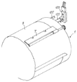
まず、図1を参照して、本実施形態に係る印刷装置の一例としての孔版印刷装置200の全体構成について説明する。
孔版印刷装置200は、図1に示すように、図1の右側上方に配置されロール状に巻かれたマスタ8を製版する製版装置16と、図1における略中央部に配置され製版されたマスタ8(以下、「製版済みのマスタ8」という)を外周面に巻装する版胴1と、この版胴1の外周面に接離自在であり該版胴1上の製版済みのマスタ8に用紙38を押し付ける押圧手段としてのプレスローラ21と、製版装置16の下方に配置され、給紙台としての給紙トレイ37上に積載された用紙38を版胴1とプレスローラ21との間に向けて給紙する給紙装置30と、版胴1およびプレスローラ21を挟んで給紙装置30に対向して配置され印刷された用紙38(以下、「印刷済みの用紙38」という)を版胴1から剥離して排紙台としての排紙トレイ59に排出する排紙装置54と、図9に示すように、版胴1および製版装置16(図9では省略している)が配設された本体フレーム130の上部に配置され原稿受け台134上から移送される原稿133の画像または読取部としてのコンタクトガラス135上に載置された図示しない原稿の画像を読み取る原稿読取装置20とを具備する。
【0027】
孔版印刷装置200は、上記した装置や構成要素の他に、排紙装置54と原稿読取装置20との間であって版胴1の左近傍に配置され版胴1の外周面から剥ぎ取られた使用済みのマスタ8を図示しない排版箱に排出する公知の排版装置(図示せず)等とを具備している。該排版装置は、例えば特許第2756224号公報(特開平7−52515号公報)の図1に記載されているものと同様の構成を具備している。
【0028】
製版装置16は、マスタ8をマスタ搬送方向X1に繰り出し可能に支持するマスタ支持手段としてのマスタ支持部材8cと、画像情報に応じて繰り出されたマスタ8を加熱製版するサーマルヘッド11と、サーマルヘッド11にマスタ8を押圧しながらマスタ搬送方向X1下流側にマスタ8を回転しながら搬送するプラテンローラ10と、プラテンローラ10により搬送されて来たマスタ8を適度の張力を付与しながらさらにマスタ搬送方向X1下流側に搬送する搬送ローラ対12,12と、製版済みのマスタ8または未製版のマスタ8を所定の長さに切断するカッタ13と、プラテンローラ10および搬送ローラ対12,12により搬送されてきたマスタ8に適度の張力を付与しながら版胴1の拡開したクランパ7に向けて搬送する反転ローラ対14,14等とを具備する。
【0029】
マスタ8は、連続シート状をなし、合成樹脂製のロール芯8bに巻き付けられてマスタロール8aが形成される。ロール芯8bはマスタロール8aの両端面から突出していてマスタ8の幅よりも長く形成されている。マスタロール8aは、両端側のロール芯8bがマスタ支持部材8cにより反時計回りに回転自在に支持されていて、マスタ支持部材8cに対して着脱自在となっている。両端側のマスタ支持部材8cは、製版装置16におけるマスタ搬送方向X1に沿ってその左右両側に配設されている図示しない製版側板対に取り付け固定されている。したがって、マスタ8は、マスタ支持部材8cによって、マスタロール8aからマスタ搬送方向X1に繰り出し可能に支持されている。
【0030】
マスタ8は、例えば厚さが1〜5μmの熱可塑性樹脂フィルムと、合成繊維等からなる多孔質支持体とを貼り合わせたラミネート構造をなす。なお、マスタは、これに限らず、例えば和紙繊維、あるいは和紙繊維および合成繊維を混抄したもの等からなる多孔質支持体と熱可塑性樹脂フィルムとを貼り合わせたものや、いわゆる実質的に熱可塑性樹脂フィルムのみからなるマスタ等も用いられる。
【0031】
サーマルヘッド11は、プラテンローラ10のプラテンローラ軸と平行に延在して設けられていて、図示しないカムおよびバネ部材等を備えた接離機構により、マスタ8を介してプラテンローラ10に接離自在となっている。サーマルヘッド11は、上記バネ部材によりプラテンローラ10に接触する向きに付勢されている。サーマルヘッド11の主走査方向には、プラテンローラ10にマスタ8を介して当接する部位に多数の発熱素子(図示せず)が配設されている。サーマルヘッド11は、図11に示すA/D変換部150および画像信号処理部151を経て、サーマルヘッド駆動制御部153で処理されて送出されるデジタル画像信号に基づき上記発熱素子を選択的に加熱することにより、マスタ8を選択的に加熱溶融穿孔・製版する製版手段としての周知の機能を有する。
【0032】
プラテンローラ10は、金属製の芯金を介してプラテンローラ軸と一体的に形成されている。プラテンローラ10は、プラテンローラ軸の両端部が上記製版側板対に回転可能に支持されていることにより、時計回りに回転自在となっている。プラテンローラ10は、タイミングベルトやギヤ等の回転伝達部材(図示せず)を介して、ステッピングモータからなるマスタ搬送モータ10aに連結され、これにより時計回りに回転駆動される。
上記構成のとおり、プラテンローラ10がマスタ搬送モータ10Aにより時計回りに回転駆動されることにより、マスタ8はマスタロール8aから引き出されることとなる。
【0033】
搬送ローラ対12,12は、バネ等の付勢手段により適度な押圧力を与えられて互いに圧接して設けられていて、各ローラ軸の両端部が上記製版側板対に回転自在に支持されていることにより互いに反対方向に回転自在となっている。搬送ローラ対12,12は、上側の搬送ローラ12がプラテンローラ10の周速度(搬送速度)よりもわずかに速い周速度(搬送速度)で回転するように、図示しない複数のギヤ等の回転伝達部材、および例えばパウダー式電磁クラッチ(図示せず)を介してマスタ搬送モータ10Aに連結されている。
マスタ搬送モータ10Aを介してのプラテンローラ10および搬送ローラ対12,12周りの駆動系は、例えば本願出願人が提案した特開平11−77949号公報の図2に示されている回転伝達機構と同じ機構を採用している。
【0034】
上記パウダー式電磁クラッチは、プラテンローラ10とサーマルヘッド11との間のニップ部からマスタ8を無理に引き摺り出さないような所定の張力としてのフロントテンションをプラテンローラ10と搬送ローラ対12,12との間のマスタ8に付与する機能を有する。上記のとおり、搬送ローラ対12,12は、マスタ8との間で滑りながら適度なフロントテンションを製版済みのマスタ8に付与するようになっている。
【0035】
カッタ13は、固定刃13bおよび可動刃13aを備えたギロチンタイプの公知のものである。カッタ13は、上記ギロチンタイプに限らず、可動刃がマスタ搬送方向X1と直行するマスタ幅方向に回転しながら移動する回転刃移動タイプのものを用いてもよい。
【0036】
反転ローラ対14,14は、カッタ13に隣るマスタ搬送方向X1下流側に配設されていて、金属製の軸と一体的に形成されている。反転ローラ対14,14は、バネ等の付勢手段により適度な押圧力を与えられて互いに圧接して設けられていて、上記各軸の両端部が上記製版側板対に回転自在に支持されていることにより互いに反対方向に回転自在となっている。上側の反転ローラ14は、複数のギヤあるいはベルト等の回転伝達部材(図示せず)を介してマスタ搬送モータ10Aに連結され、これにより時計回りに回転駆動される。
【0037】
反転ローラ対14,14は、マスタ搬送モータ10Aを含む上記回転伝達部材によって、プラテンローラ10の周速度(搬送速度)よりも速い周速度(搬送速度)で回転するように設定されていて、マスタ8との間で滑りながら適度のフロントテンションをマスタ8に付与するようになされている。上側の反転ローラ14の軸端には、自身へのマスタ搬送モータ10Aの回転駆動力を断接する電磁クラッチ(図示せず)が設けられている。該電磁クラッチは、例えば、パウダー式電磁クラッチもしくはヒステリシス式電磁クラッチからなる。なお、上記電磁クラッチに代えて、マスタ搬送モータ10Aとは独立したステッピングモータで単独駆動してもよい。
反転ローラ対14,14に隣るマスタ搬送方向X1下流側には、製版済みのマスタ8の先端を版胴1のクランパ7に案内するための湾曲したガイド板15が反転ローラ対14,14の各軸方向に延在して設けられている。
【0038】
版胴1は、多孔性で円筒状の支持円筒体と、その支持円筒体の外周を覆うように複数層巻き付けられた樹脂あるいは金属網体製のメッシュスクリーン(図示せず)との2層構造からなる。版胴1は、インキ通過性の多数の開孔を有する開口部1a(印刷可能領域)と、クランパ7等が設けられている非開口部(非印刷可能領域)とを備えた周知の構成を有する。版胴1は、図示しない端板フランジの外周部に巻着・固設されていて、後述するインキパイプ5を兼ねる支軸5の周りに回転自在に支持されている。
【0039】
版胴1の大きさは、実施例的に言えば、例えばA3サイズの用紙38に印刷を行うことが可能なA3サイズの大きさ、すなわちA3サイズの1版のマスタ8を巻装可能な大きさを有しており、その外周直径が180mm(版胴1の外周長としては約565mm)に、その幅方向(回転中心軸線方向)の寸法が350mm程度に設定されている。
【0040】
版胴1は、図示しないギヤやベルト等の駆動伝達手段を介してメインモータ17に連結されていて、メインモータ17により図中矢印方向(時計回り)に回転駆動される。メインモータ17としては、例えば制御用のDCモータが使用されている。メインモータ17の出力軸17aには、光学式のロータリエンコーダ18とこれを挟み付けてロータリエンコーダ18との協働作用によりパルスを発生する版胴センサ19が設けられている。この版胴センサ19は、透過型の光学センサからなり、版胴1の回転速度(印刷速度)の制御や回転位置の割り出し等のために用いられる。
【0041】
版胴1の内部には、図示しない側板に回転自在に支持されていて、図示しないギヤ等の駆動伝達手段によりメインモータ17の回転駆動力が伝達されて版胴1と同期して図中矢印方向(時計回り)に回転駆動され、版胴1の内周面に接触してインキを供給するインキローラ2と、インキローラ2とわずかな間隙を置いて平行に配置されインキローラ2との間に断面楔状のインキ溜まり4を形成するドクタローラ3と、インキ溜まり4へインキを供給するインキパイプ5とが配置されている。インキローラ2、ドクタローラ3およびインキパイプ5がインキ供給手段を構成する。
インキ溜まり4のインキは、版胴1の外部に設けられた図示しないインキパック等より図示しないインキポンプで吸引され、インキパイプ5の供給孔より供給されて混練される。インキ溜まり4のインキは、ドクタローラ3により計量されながらインキローラ2の外周面上に薄膜状に供給され、さらにインキローラ2の外周面が版胴1の上記支持円筒体内周面に接触することにより版胴1の開口部1a部分に供給される。
【0042】
版胴1の上記非開口部外周面上の一部分には、版胴1の一つの母線に沿って設けられた強磁性体製のステージ6と、このステージ6の両側端に設けられたクランパ軸に回動自在に取り付けられ、ステージ6の平面部に対して開閉自在なゴム磁石を有するクランパ7とがそれぞれ設けられている。クランパ7は、図示しない本体フレーム側に設けられた開閉装置(図示せず)により所定位置において開閉される。版胴1は、クランパ7が図1に示す略右横に位置する状態、すなわち給版位置において停止されるようになっている。版胴1は、上記インキパックや上記インキポンプ等と一体的になされた版胴ユニットとして構成されており、孔版印刷装置200の上記本体フレームに対してインキパイプ5の軸線方向に挿脱自在になっている。
【0043】
図1において紙面奥側の版胴1の端板フランジおよびこの端板フランジ近傍の上記本体フレーム側には、図5に示すように、版胴1の回転位置を検出することにより給紙装置30の図1および図6に示す給紙モータ45およびレジストモータ50への起動(スタート)・トリガ情報を与える構成要素が配設されている。すなわち、図5に示すように、版胴1における右奥側の上記端板フランジの外側壁には、給紙開始用遮光板121とレジスト開始用遮光板122とが版胴1の同円周上に所定の間隔をおいてそれぞれ取り付けられている。
【0044】
一方、各遮光板121,122近傍の上記本体フレーム側には、給紙開始用遮光板121とレジスト開始用遮光板122とが取り付けられている版胴1の同円周上に対向してこれらを挟む態様で、給紙レジストセンサ120が取り付けられている。給紙レジストセンサ120は、発光部および受光部を具備する透過型の光学センサである。
【0045】
インキローラ2に対向する版胴1の外周面の下方近傍には、プレスローラ21が配設されている。プレスローラ21は、版胴1上の製版済みのマスタ8に用紙38を押し付ける印刷位置とこの印刷位置から離れた非印刷位置(図1に示す初期位置でもある)との間で変位自在に構成されている。
プレスローラ21が版胴1の外周面から離間する点(押圧領域の後端)は、インキ付着によるプレスローラ21の汚れを防止するために、製版済みのマスタ8の版胴1への巻装長さよりもやや短めに設定されている。プレスローラ21の版胴1に対する押圧範囲は、図1に示すように、版胴1の開口部1aの前縁部分P1より当接し、版胴1上に巻装されている製版済みのマスタ8の後縁手前部分P2で版胴1から離間するように設定されている。
【0046】
プレスローラ21における図1より見て奥側の端部には、プレスローラ21を、印刷位置と非印刷位置との間で変位させるための変位手段29が配設されている。変位手段29は、アーム軸22a、プレスアーム対22,22、加圧アーム23、カムフォロア24、加圧バネ25、印圧カム軸26および印圧カム27等から主に構成されている。
【0047】
アーム軸22aは、上記本体フレーム側に固設された筐体側板(図示せず)に回転自在に支持されている。プレスローラ21は、その横幅が版胴1の開口部1aの横幅よりもやや長い長さとなるように形成されており、その中心部にはプレスローラ軸21aが挿通固着されている。プレスローラ軸21aの両端部は、図1における紙面の手前側および奥側に配置されたアーム軸22aにその一端側が固定されたプレスアーム対22,22の他端側に回転自在に支持されていて、版胴1上の製版済みのマスタ8に用紙38を介して圧接したときに従動回転するようになっている。
【0048】
アーム軸22aの端部には、加圧アーム23の一端部が固着されている。加圧アーム23の略中央部には、カムフォロア24が回転自在に軸を持って保持されている。加圧アーム23の他端部側には、プレスローラ21を常に版胴1の外周面に圧接する向きに付勢する加圧バネ25(引張バネ)の一端が係止され、加圧バネ25の他端は上記筐体側板側に係止されている。この加圧バネ25により、加圧アーム23の他端側は、アーム軸22aを中心として時計回りに揺動する向きに付勢されている。加圧アーム23の他端部には、後述する係止部材60の係止爪60aと係合可能な切欠23aが一体的に形成されていて、係止部材60と係脱可能となっている。
【0049】
一方、図1および図2に示すように、カムフォロア24近傍の上記筐体側板には、版胴1の回転と同期して回転する印圧カム27を固着した印圧カム軸26が回転自在に支持されている。印圧カム27は、小径部と大径部とが形成された例えば板カムからなる。
印圧カム軸26には、図示しないベルトプーリまたはギヤ等が固設されていて、印圧カム軸26は、図示しないベルトやギヤ等の駆動伝達手段を介してメインモータ17に連結されている。これにより、印圧カム27は、版胴1の回転と同期して回転するようになっている。加圧バネ25により、カムフォロア24は印圧カム27に常に当接する向きに付勢されている。したがって、プレスローラ21を駆動する押圧駆動手段は、メインモータ17、加圧バネ25および印圧カム27から主に構成されている。
【0050】
なお、変位手段29を構成する加圧アーム23、カムフォロア24、加圧バネ25および印圧カム27等は、上述したように図1の紙面の奥側のみに配設する例に限らず、プレスローラ21の均一な押圧力を版胴1の外周面に付与すべく、プレスアーム対22,22と同様に、図1の紙面の手前側に同一形状および同一位相をもって配設しても勿論構わない。
【0051】
図1において、符号64は、通紙時以外はプレスローラ21を図1に示す非印刷位置(厳密には非印刷位置よりもさらに僅かに離間した初期位置である)で保持するための係止手段を示す。係止手段64は、印圧解除手段とも呼ばれており、係止部材60、支軸61、第1ソレノイド62および引張バネ63から主に構成される。
【0052】
係止部材60は、上記筐体側板に植設された支軸61の周りに揺動自在になされていて、その一端部には上記した係合爪60aが一体的に形成されている。係止部材60の他端部には、係合爪60aを加圧アーム23の切欠23aに常に係合する向きに付勢する引張バネ63の一端が形成されている。引張バネ63の他端は、上記筐体側板側に係止されている。また、係止部材60の他端部における引張バネ63の配置部と対向する側には、上記筐体側板に固設された第1ソレノイド62のプランジャ62aがピンを介して連結されている。第1ソレノイド62は、プル型を用いている。
【0053】
上述した構成のとおり、第1ソレノイド62に通電されて第1ソレノイド62がオンされることにより、変位手段29を作動させることとなり、後述する詳細動作を介してプレスローラ21が印刷位置を占める。これによって、プレスローラ21は用紙38を版胴1上の製版済みのマスタ8に従動回転しながら連続的に押し付ける。第1ソレノイド62への通電が遮断され第1ソレノイド62がオフされることにより、変位手段29を非作動にさせることとなり、後述する詳細動作を介してプレスローラ21が印刷位置から離れた図1に示す非印刷位置(初期位置)を占める。第1ソレノイド62は、後述する制御装置100によりオン/オフ制御される。
【0054】
図1ないし図4において、符号79は、プレスローラ21の版胴1に対する押圧を緊急的に解除する緊急押圧解除手段を示す。緊急押圧解除手段79は、解除カムギヤ65、解除カム駆動ギヤ66、解除カム67、解除カム軸68、クラッチギヤ70、クラッチ胴71、スリーブ72、スプリングクラッチ73、カム駆動軸74、カム駆動ギヤ75、ストッパ76、第2ソレノイド77、スプリング78から主に構成される。
【0055】
図2に示すように、解除カム67は、解除カムギヤ65と一体的に固設されており、印圧カム軸26に回転自在に支持されている。解除カム67は、印圧カム27と別体的に設けられていて、小径部と大径部とが形成された例えば板カムからなり、印圧カム27と同様の形状を有している。解除カム軸68は、上記筐体側板に回転自在に支持されている。解除カムギヤ65は、解除カム軸68の一端側に固設された解除カム駆動ギヤ66と常時噛み合っている。印圧カム軸26と解除カム軸68とは、互いに反対方向に回転駆動されるようになっている。本実施例では図1に示すように、印圧カム27および印圧カム軸26は時計回りに、解除カム駆動ギヤ66は反時計回りに回転し、解除カム駆動ギヤ66で駆動される解除カム67は印圧カム27と同じ時計回りに回転される。
【0056】
解除カム軸68の他端側には、クラッチ胴71が固設されている。クラッチギヤ70は、解除カム軸68の他端側に回転自在に支持されている。クラッチギヤ70とクラッチ胴71との間には、スプリング73aを巻き付けて構成されたスプリングクラッチ73が介装されている。後述するように、クラッチギヤ70からスプリングクラッチ73を介してクラッチ胴71に回転力が伝達されるようになっている。
【0057】
スプリングクラッチ73には、その外周部に扇形の凸部72aを有するスリーブ72が設けられている。スプリングクラッチ73におけるスプリング73aの一端は、クラッチギヤ70の右側突出部外周に巻かれていると共にスリーブ72に固定され、スプリングクラッチ73におけるスプリング73aの他端は、クラッチ胴71に固定されている。それ故に、クラッチ胴71、スリーブ72およびスプリングクラッチ73は、一体的に回転するように構成されている。
スプリングクラッチ73は、回転駆動の方向に合わせてスプリング73aの巻き方向が設定されており、回転力伝達時にスプリング73aが巻き込まれてスプリング内径が小さくなるように上記巻き方向が決められ、いわゆる一方向性クラッチ(ワンウェイクラッチ)として使用されるものである。
【0058】
クラッチギヤ70の近傍には、上記筐体側板に回転自在に支持され、メインモータ17の回転力が伝達されて駆動されるカム駆動軸74が設けられている。カム駆動軸74の端部にはカム駆動ギヤ75が固設されていて、このカム駆動ギヤ75は、クラッチギヤ70と常時噛み合っていてクラッチギヤ70を反時計回りに回転駆動する。
本実施形態ではカム駆動軸74を駆動する駆動手段は、メインモータ17の回転力が図示しない回転伝達手段を介して伝達される構成による駆動手段を採用しているが、これに限らず、メインモータ17と別個に設けられ少なくとも印刷時に回転駆動される、あるいは常時回転駆動される電動モータ等であってもよい。
【0059】
図3および図4に示すように、クラッチ胴71およびスリーブ72の近傍の上記筐体側板には、ストッパ支軸76Aに軸支された略U字形のストッパ76が配設されている。ストッパ76は、例えば板金等でできていて、ストッパ76の両端部には、スリーブ72の凸部72aと選択的に係合する第1係合部76aおよび第2係合部76bが形成されている。
【0060】
第1係合部76a形成側のストッパ76の端部には、第2ソレノイド77のプランジャがピンを介して連結されており、後述する制御装置100によりオン/オフ制御される。第2ソレノイド77は、プル型を用いており、上記筐体側板側に固定されている。ストッパ76と第2ソレノイド77本体との間には、圧縮バネからなるスプリング78がプランジャ77aに巻着される態様で介装されている。それ故に、スプリング78の付勢力によって、ストッパ76はストッパ支軸76Aを中心として常に図において時計回りに揺動する習性を与えられている。上記のとおり、第2ソレノイド77および上記駆動手段は、解除カム67を駆動する解除カム駆動手段としての機能を有する。
【0061】
図3および図4に示されている何れの状態においても、スリーブ72の凸部72aは、ストッパ76の第1係合部76a、第2係合部76bに突き当て・係合していて、その回転を阻止・停止させられており、カム駆動軸74の回転は解除カム軸68に伝達されない。これらの状態では、ストッパ76によるスリーブ72の回転阻止力の方が、クラッチギヤ70の右側突出部外周面とこれに巻かれているスプリング73aとの間の摩擦力より大きいためクラッチギヤ70は空転しているだけである。したがって、カム駆動軸74の回転は解除カム軸68に伝達されず、解除カム67はその位置に停止したままである。
【0062】
図3に示すように、ストッパ76の第1係合部76aがスリーブ72の凸部72aと係合していてスリーブ72の回転が阻止されている状態では、クラッチギヤ70とクラッチ胴71との連結は断たれていて、図1に示すように解除カム67の大径部はカムフォロア24の略反対側で保持されるようになっている。図3に示す状態から図4に示すように、第2ソレノイド77に通電されて第2ソレノイド77がオンされることにより、プランジャ77aがスプリング78の付勢力に抗して図4中矢印上向きに引き上げられることによって、ストッパ76の第1係合部76aとスリーブ72の凸部72aとの係合が解除されると、図2においてスプリングクラッチ73が接続された状態となる。
これにより、カム駆動軸74の回転がスプリングクラッチ73を介してクラッチ胴71に伝達される。すなわち、クラッチ胴71、スリーブ72、スプリングクラッチ73およびクラッチギヤ70が一体で矢印で示す反時計回り方向に回転し、上記駆動手段の回転力が解除カム軸68、解除カム駆動ギヤ66と噛合する解除カムギヤ65を介して解除カム67に伝達されて、解除カム67の大径部が図1において略右真横位置まで回転してカムフォロア24を押し付けることとなる。
【0063】
そして、クラッチ胴71が矢印で示す反時計回り方向に所定角度回転して、図4に示すように、ストッパ76の第2係合部76bがスリーブ72の凸部72aに係合することによりスリーブ72の回転を阻止されると、スプリングクラッチ73の接続が再び断たれて、解除カム67の大径部が図1において略反対位置まで回転した後にその位置で保持される。これにより、カムフォロア24が解除カム67の大径部に乗り上げた状態で保持されて、プレスローラ21が版胴1との押圧状態から緊急的に離間して非印刷位置を占めた状態で保持される。
【0064】
次いで、所定時間後、第2ソレノイド77への通電が遮断されて第2ソレノイド77がオフされると、スプリング78の付勢力によってストッパ76が上記したとは反対の時計回りに回転することにより、ストッパ76の第2係合部76bとスリーブ72の凸部72aとの係合が解除されることで、スプリングクラッチ73が再度接続された状態となり、これにより上記したと同様にクラッチ胴71等とクラッチギヤ70が一体で回転し、上記駆動手段の回転力が解除カム軸68、解除カム駆動ギヤ66と噛合する解除カムギヤ65を介して解除カム67に伝達されて、解除カム67の大径部が図1に示す位置近傍に回転され、次いでストッパ76が所定角度回転して図3に示すようにストッパ76の第1係合部76aがスリーブ72の凸部72aと係合することによって、スプリングクラッチ73の接続が再度断たれて、解除カム67の大径部が図1に示す初期位置まで回転した後その位置で保持される。なお、解除カム67が動作するときには、係止手段64の第1ソレノイド62がオフ制御されることにより、プレスローラ21が非印刷位置に保持されるようになっている。
【0065】
給紙装置30は、図1および図7に示すように、用紙38を繰り出し可能に積載して昇降自在な上記した給紙トレイ37と、給紙トレイ37上の用紙38に接触してレジストローラ対31,32のニップ部に向けて用紙38を1枚ずつ分離して搬送する給紙手段としての給紙ローラ35および分離部材36と、用紙38の用紙サイズを検出する用紙サイズ検出手段109と、版胴1の外周面とプレスローラ21との間に後述するタイミングを取って用紙38を給送するレジスト手段としてのレジストローラ対31,32等とを具備している。
【0066】
給紙トレイ37は、図示しない給紙トレイ昇降モータおよびワイヤ式昇降機構等を備えた駆動装置(図示せず)により、積載された用紙38の最上位が常に給紙ローラ35に所定の押圧力(用紙38が搬送可能な押圧力)をもって接触するように、すなわち用紙38の増減に連動して用紙38が搬送可能な範囲の押圧力で接触する状態を保持しつつ昇降される。給紙トレイ37は、多くの用紙種類および用紙サイズを使用できる構造を有すると共に、その用紙積載容量を例えば用紙サイズA3やA4の用紙38で500枚以上を積載可能とする孔版印刷装置に適した構造を有する。
【0067】
給紙トレイ37には、図7に示すように、用紙サイズに応じて用紙38の両側端を位置決め揃えるための一対のサイドフェンス110a,110bが用紙幅方向Yに移動自在に配設されている。図7において、用紙サイズ検出手段109は、サイドフェンス対110a,110bの用紙幅方向Yの移動に連動して用紙38の用紙サイズを決定するものである。
用紙サイズ検出手段109は、移動自在なサイドフェンス対110a,110bと、給紙トレイ37の下部に配設されている不動部材に回動自在に取り付け支持されたピニオン116と、サイドフェンス110aの下部端縁部に形成されピニオン116と噛み合うラック部115と、サイドフェンス110bの下部端縁部に形成されラック部115に対向してピニオン116と噛み合うラック部114と、サイドフェンス110bのラック部114に対向する下部端縁部において下方に突出して折り曲げられ適宜の間隔をもって切り欠かれた複数の切欠きを備えた遮閉部114aと、給紙トレイ37の上記不動部材に適宜の間隔をもって固設され遮閉部114aとそれぞれ選択的に係合する複数(ここでは2つ)の横サイズ検知センサ118a,118bと、給紙トレイ37の上記不動部材における給紙方向Xに適宜の間隔をあけて固設された複数(ここでは3つ)縦サイズ検知センサ119a,119b,119cとから主に構成されている。
【0068】
各横サイズ検知センサ118a,118bは、発光部および受光部を具備した透過型の光学センサであり、遮閉部114aとそれぞれ選択的に係合することにより用紙38における用紙幅方向Yの長さ・サイズを検出する。縦サイズ検知センサ119a,119b,119cは、反射型の光学センサである。縦サイズ検知センサ119a,119b,119cは、用紙38における給紙方向Xの長さ・サイズを検知する。各横サイズ検知センサ118a,118bおよび各縦サイズ検知センサ119a,119b,119cを総称して、用紙サイズ検知センサ群117という。用紙サイズ検知センサ群117は後述する制御装置100に電気的に接続されており、これらの用紙サイズ検知センサ群117で検出されたサイズ信号データを組み合わせて制御装置100のCPU101が判断することにより、用紙38の用紙サイズを決定するものである。用紙サイズ検知センサ群117は、用紙38の用紙サイズを検知する用紙サイズ検知手段としての機能を有する他、縦サイズ検知センサ119aは用紙38の有無を検知する用紙有無検知手段としての機能も有する。
【0069】
なお、用紙38における用紙幅方向Yの長さ・サイズを検出する横サイズ検知センサおよび用紙38における給紙方向Xのサイズを検知する縦サイズ検知センサとしては、説明の簡明化のためにそれぞれ2つおよび3つとしたが、これ以上配設してより多くのサイズを検知できるようにすることが好ましい。
このような用紙サイズ検知方式の詳細としては、本願出願人が以前に提案した、例えば特開平9−30714号公報等に開示されている技術を挙げることができる。用紙サイズ検知方式としては、上述したような方式に限定されず、他の方式、例えば給紙側板(サイドフェンス)に連動して摺動子がスライドして、用紙サイズに応じて配置されている紙サイズ検知板の各端子と接触・接続して検知するもの等であってもよい。
【0070】
給紙ローラ35は、図6に示すように、金属製の給紙ローラ軸35aと一体的に形成されていて、給紙ローラ軸35aの一端部が上記筐体側板に回転自在に支持されている。給紙ローラ軸35aの一端部には、歯付きの給紙ローラプーリ47が取り付けられている。給紙ローラ軸35aと給紙ローラプーリ47との間には、用紙搬送方向Xにのみ用紙38を搬送するように給紙ローラ35を回転させる、つまり時計回りにのみ回転させるためのワンウェイクラッチ(図示せず)が配設されている。
【0071】
分離部材36は、用紙38に対する摩擦係数の高いゴムや樹脂で形成され給紙ローラ35に当接可能となっている分離パッドと呼ばれる部材を有している。この分離パッドは、付勢手段としての図示しない圧縮バネにより給紙ローラ35に押し付けられる向きに付勢されている。
【0072】
図6に示すように、給紙ローラプーリ47の下方には、給紙ローラ35を回転駆動する給紙駆動手段としての給紙モータ45が上記筐体側板に固定して設けられている。給紙モータ45は、パルス入力で駆動するモータとしての例えばステッピングモータからなり、その出力軸には歯付きの給紙モータプーリ46が固設されている。給紙ローラプーリ47と給紙モータプーリ46との間には、歯付きの給紙モータベルト48が掛け渡されている。これにより、給紙ローラ35と給紙モータ45とは給紙モータベルト48およびを上記ワンウェイクラッチを介して回転駆動力伝達関係にある。
【0073】
図1および図6に示すように、レジストローラ上31は金属製のレジストローラ軸31aと、レジストローラ下32は金属製のレジストローラ軸32aとそれぞれ一体的に形成されていて、各レジストローラ軸31a,32aの両端部が上記筐体側板に回転自在に支持されている。下側のレジストローラ軸32aの一端部には、歯付きのレジストローラプーリ52が取り付けられている。
【0074】
レジストローラ下32は、レジストローラ軸32aを介して、上記筐体側板に移動不能にかつ回転自在に支持されている。レジストローラ上31は、レジストローラ下32に対して所定のタイミングで当接するように接離自在に設けられている。
図8において、符号40は、レジストローラ上31をレジストローラ下32に所定のタイミングで当接させるレジストローラ接離手段を示す。レジストローラ接離手段40は、レジストアーム41、レジストアーム軸41a、駆動アーム42、カムフォロア42A、レジストカム43、加圧スプリング44から主に構成される。
【0075】
レジストアーム41の基端は、上記筐体側板に回転自在に支持されたレジストアーム軸41aに固設されていて、レジストアーム41の自由端は、レジストローラ上31のレジストローラ軸31aを回転自在に支持している。レジストアーム軸41aには、自由端にカムフォロア42Aを回転可能に支持した駆動アーム42の基端がレジストアーム41に対して略直交する角度で固設されている。それ故に、レジストアーム41および駆動アーム42は、レジストアーム軸41aの周りに略L字形状をなして一体で揺動可能となっている。
【0076】
カムフォロア42Aの近傍には、上記筐体側板に回転自在に軸を持って支持され大径部および小径部を有するレジストカム43がカムフォロア42Aに対向して配設されている。駆動アーム42の略中央部と上記筐体側板との間には、加圧スプリング44(引張バネ)が張設されている。加圧スプリング44の付勢力によって、カムフォロア42Aはレジストカム43の大径部に当接する向きの習性を、またレジストローラ上31はレジストローラ下32に当接する向きの習性をそれぞれ常時付与されている。レジストカム43の軸は、図示しない回転伝達手段を介してメインモータ17に連結されていて、版胴1の回転と同期して回転するようになっている。したがって、レジストローラ上31は、レジストローラ接離手段40によって、レジストローラ下32に対して所定のタイミングで当接することとなる。
【0077】
図8に示すように、レジストカム43の小径部がカムフォロア42Aと非接触で対向している状態・時機では、レジストローラ上31はレジストローラ下32に当接していて、これにより形成されるニップ部で用紙38を挟持し搬送可能な状態とされる。
【0078】
図1および図6に示すように、レジストローラ下32の下方には、レジストローラ対31,32を回転駆動するレジスト駆動手段としてのレジストモータ50が上記筐体側板に固定して設けられている。レジストモータ50は、パルス入力で駆動するモータとしての例えばステッピングモータからなり、その出力軸には歯付きのレジストモータプーリ51が固設されている。レジストローラプーリ52とレジストモータプーリ51との間には、歯付きのレジストモータベルト53が掛け渡されている。これにより、レジストローラ下32とレジストモータ50とはレジストモータベルト53を介して回転駆動力伝達関係にある。
【0079】
図1において、レジストローラ対31,32の配置位置から給紙ローラ35および分離部材36で構成される分離搬送部までの用紙搬送経路XAには、給紙ローラ35により搬送された用紙38の先端および後端を検知する第1の用紙検知手段としての第1用紙センサ33が配設されている。第1用紙センサ33は、第1用紙センサ33の配置位置(用紙38の先端を検知できる位置)よりも上流側の用紙搬送経路XAに用紙38が留まっていることを検知する機能も有する。
【0080】
また、版胴1とプレスローラ21との間からレジストローラ対31,32のニップ部までの用紙搬送経路XAには、レジストローラ対31,32から送り出された用紙38の先端および後端を検知する第2の用紙検知手段としての第2用紙センサ34が配設されている。第2用紙センサ34は、第2用紙センサ34の配置位置(用紙38の先端を検知できる位置)よりも上流側であって第1用紙センサ33の配置位置(用紙38の先端を検知できる位置)よりも下流側の用紙搬送経路XAに用紙38が留まっていることを検知する機能も有する。
第1用紙センサ33および第2用紙センサ34は、発光部および受光部を具備した反射型の光学センサである。
【0081】
なお、第1用紙センサ33の配置位置(用紙38の先端が検知できる位置)から給紙ローラ35のニップ部中心までの用紙搬送経路XAの距離は、給紙トレイ37に積載して搬送可能な例えばハガキサイズの長さよりも少なくとも短く設定されている。それ故に、例えばハガキの先端がレジストローラ対31,32のニップ部で挟持され給送状態にあるハガキの後端は、少なくとも給紙ローラ35と分離部材36とで挟持されている状態にある。
【0082】
排紙装置54は、図1に示すように、版胴1の外周面に近接自在に設けられ、印刷済みの用紙38を版胴1上の製版済みのマスタ8から剥離する剥離爪55と、剥離爪55で剥離された印刷済みの用紙38を吸引しつつ搬送する吸着搬送装置56と、上記した排紙トレイ59とから主に構成されている。
【0083】
吸着搬送装置56は、搬送ローラ前57aと搬送ローラ後57bとの間に張設された多孔性の搬送ベルト57cと、回転することにより印刷済みの用紙38を搬送ベルト57c上に吸着する吸引ファン58とから構成されている。搬送ローラ後57bは、図示しない排紙駆動モータにより回転駆動される。吸引ファン58は、内蔵されたファンモータにより回転駆動される。搬送ベルト57cは、上記駆動モータにより版胴1の周速度よりも速い搬送速度で駆動されるように設定されている。
【0084】
剥離爪55は、版胴1の外周面にプレスローラ21が圧接することにより形成される印刷ニップ部における下流近傍に設けられている。剥離爪55は、版胴1の回転と同期して回転駆動されるカムおよびバネ等を具備した剥離爪変位手段(図示せず)により、版胴1の外周面に近接して版胴1上の製版済みのマスタ8から印刷済みの用紙38を強制的に剥離する剥離位置と、この剥離位置から離間して版胴1の外周面から突出したクランパ7配置部との接触を避ける非剥離位置との間で変位自在に構成されている。
【0085】
吸着搬送装置56における用紙排出方向の上流側であって搬送ベルト57cの下方近傍には、剥離された印刷済みの用紙38の先端および後端を検知する排紙検知手段としての排紙センサ39が配設されている。排紙センサ39は、反射型の光学センサである。排紙センサ39配置部の搬送ベルト57cの真上周辺には、上記光学センサからの出射光および反射光を通すための図示しない開口部が設けられている。
【0086】
原稿読取装置20は、図9に示すように、複数枚の原稿133を積載する上記した原稿受け台134と、原稿133を載置する読取部としてのコンタクトガラス135と、原稿133を搬送する原稿搬送ローラ対136および原稿搬送ローラ137と、搬送される原稿133をガイドするガイド板138,139と、原稿133をコンタクトガラス135に沿って搬送する複数の原稿搬送ベルト140と、読み取られた原稿133を積載する原稿トレイ141と、コンタクトガラス135を除く上記各部材を支持しコンタクトガラス135に対して接離・開閉自在に設けられた圧板142と、原稿133の画像を照明しつつ走査して読み取るための反射ミラー143,144および蛍光灯145と、走査して読み取られた画像の反射光を集束するレンズ146と、集束された画像の反射光を処理するCCD(電荷結合素子)等を備えた画像センサ147等とを具備している。
【0087】
上記構成中、原稿受け台134、原稿搬送ローラ対136、原稿搬送ローラ137、各ガイド板138,139、原稿搬送ベルト140および原稿トレイ141によって、コンタクトガラス135(読取部)上に原稿133を1枚ずつ給送する自動原稿給送手段としての自動原稿搬送装置(以下、「ADF」という)148が構成されている。また、コンタクトガラス135、各反射ミラー143,144、蛍光灯145、レンズ146および画像センサ147によって、原稿133の画像をコンタクトガラス135(読取部)上で読み取る原稿読取手段としてのスキャナ装置132が、各反射ミラー143,144、蛍光灯145およびレンズ146によって原稿走査光学系が、それぞれ構成されている。
【0088】
画像センサ147は受光した反射光に対応して光電変換をし、これにより得られた画像信号を図11に示すアナログ/デジタル(以下、「A/D」と略記する)変換部150に入力する。
【0089】
コンタクトガラス135の下方近傍には、搬送される原稿133またはコンタクトガラス135上に載置された図示しない原稿の図において搬送方向(左右方向)の原稿の長さを検知する原稿縦サイズ検知センサ149a,149bおよび搬送される原稿133またはコンタクトガラス135上に載置された図示しない原稿の図において紙面の手前側および奥側の長さを検知する図示しない原稿横サイズ検知センサが配設されている。原稿縦サイズ検知センサ149a,149bおよび上記原稿横サイズ検知センサによって、搬送される原稿133またはコンタクトガラス135上に載置された図示しない原稿のサイズが検知され、以下、これらを原稿サイズ検知センサ群149と総称する。
原稿サイズ検知センサ群149の原稿縦サイズ検知センサ149a,149bおよび上記原稿横サイズ検知センサは、共に反射型の光学センサであり、コンタクトガラス135上における反射量の違いにより原稿133の輪郭・サイズおよび原稿133の有無を検知する。原稿サイズ検知センサ群149からの信号は、後述する制御装置100に入力される。原稿サイズ検知センサ群149からの信号に基づいて、制御装置100は原稿サイズ(等倍のときには、マスタ8に製版・形成されるべき製版画像のサイズでもある)を判定し認識する。原稿受け台134の下方には、原稿受け台134上に残存している原稿133を検知する原稿検知センサ131が配設されている。原稿検知センサ131は、原稿受け台134上の原稿133が無くなったときに制御装置100に信号を出力する。
【0090】
次に、図10を参照して操作パネル80の細部構成を説明する。
操作パネル80は、孔版印刷装置200に所定の動作等をさせるべく指示等をするためのものであり、図9に示した原稿読取装置20の近傍に配設されている。操作パネル80には、図10に示すように、原稿画像の読み取りから排版、製版、給版、給紙、版付け印刷(以下、「版付け」という)、排紙工程に至るまでの一連の工程(動作)を起動するための製版起動手段としての製版スタートキー81と、印刷枚数等を設定・入力するためのテンキー83と、このテンキー83で設定・入力された印刷枚数分の印刷動作の起動を行うための印刷スタートキー82と、原稿サイズに対してマスタ8に製版・形成されるべき製版画像のサイズ、すなわち印刷画像サイズを拡大したり縮小したりする際の変倍率を設定するための図示しない変倍率設定キーと、操作の状態やメッセージあるいは各種キーで選択されている機能等の表示をしたり、その機能を選択・設定するための操作内容を随時表示したりする液晶表示部85と、版胴1の回転速度である印刷速度の設定値としての印刷速度レベル1〜5の5段階の中から1つの印刷速度を選択的に設定するための印刷速度設定手段としての速度ダウンキー88aおよび速度アップキー88bを備えた印刷速度設定キー88と、速度ダウンキー88aまたは速度アップキー88bにより設定された設定印刷速度を表示するためのLED(発光ダイオード)ランプ群からなる速度表示器89とが配置されている。
【0091】
液晶表示部85は、孔版印刷装置200に係る各種情報を報知する報知手段としての機能を有する。液晶表示部85は、図示しない液晶駆動回路を介して駆動され、各種メッセージや警告を表示するメッセージ表示部86と、マスタ8や用紙38のジャム箇所等を絵で表示する絵表示部87とを有し、下位概念的には情報を表示する表示手段としての機能を有する。さらに具体的には、液晶表示部85は、用紙サイズと原稿サイズ(つまり、製版済みのマスタ8における単一の製版画像または複数の製版画像のサイズ)とが合っていないときや、上記変倍率設定キーにより設定された変倍率と用紙サイズとが合っていないときに、その旨の表示を行う機能も有する。
【0092】
速度表示器89において、中央部のハッチングを施した「設定印刷速度:3速」は、通常使用される印刷速度に対応した標準印刷速度であって、速度ダウンキー88aまたは速度アップキー88bを押下しなかった場合に自動的に設定されるようになっている。速度表示器89は、速度ダウンキー88aまたは速度アップキー88bの1回ごとの押下により、1から5までの5段階の設定印刷速度に切り換えられる印刷速度を点灯表示する。速度ダウンキー88aおよび速度アップキー88bは、速度表示器89の近傍に配置されていて、1回押すごとに、印刷速度:1速〜5速の何れか1つの印刷速度に対応した各LEDランプの点灯を順次切り換える機能も有しており、これにより、ユーザが選択した印刷速度が速度表示器89にて目視確認できるようになっている。
【0093】
操作パネル80は、上記したものの他に、本実施形態に特有の構成を有している。すなわち、操作パネル80には、図11に示す画像信号処理部151およびサーマルヘッド駆動制御部153を介してサーマルヘッド11を駆動させて版胴1の回転方向に沿って1版のマスタ8に分割された複数の同一製版画像を形成する同一画像製版モードを設定するための同一画像製版モード設定手段としての同一画像製版モード設定キー97と、図11に示す画像信号処理部151およびサーマルヘッド駆動制御部153を介してサーマルヘッド11を駆動させて版胴1の回転方向に沿って1版のマスタ8に分割された複数の異種製版画像を形成する異種画像製版モードを設定するための異種画像製版モード設定手段としての異種画像製版モード設定キー98と、サーマルヘッド11が1版のマスタ8に対して1枚の用紙38を対象とし製版画像を形成する第1の製版処理を行い、かつ、第1の製版処理されたマスタ8を巻装した版胴1の1回転中に1枚の用紙38を対応させて印刷する第1の印刷モードが設定されていることを表示するための第1の印刷モード設定表示手段としての第1の印刷モード設定表示ランプ95と、サーマルヘッド11が1版のマスタ8に対して複数枚の用紙38を対象とし版胴1の回転方向に沿って分割された複数の製版画像を形成する第2の製版処理を行い、かつ、第2の製版処理されたマスタ8を巻装した版胴1の1回転中に複数枚の用紙38を対応させて印刷する第2の印刷モードを設定するための第2の印刷モード設定手段としての第2の印刷モード設定キー96と、用紙サイズを手動で設定するための用紙サイズ設定手段90を構成するA4サイズ設定キー91およびA3サイズ設定キー92と、原稿サイズを手動で設定するための原稿サイズ設定手段106を構成するA4サイズ設定キー107およびA3サイズ設定キー108とが配置されている。
【0094】
同一画像製版モード設定キー97および異種画像製版モード設定キー98の下部(図10の紙面の奥側)には、LEDが配設されていて、同一画像製版モード設定キー97または異種画像製版モード設定キー98が押されたときに上記LEDが点灯して同一画像製版モードまたは異種画像製版モードが設定されたことが表示されるようになっている。
【0095】
第1の印刷モード設定表示ランプ95は、例えばLEDからなる。第1の印刷モード設定表示ランプ95は、孔版印刷装置200に配置されている図示しない電源スイッチが投入された直後の初期状態や、第2の印刷モード設定キー96が2回押されたときに自動的に点灯して第1の印刷モードが自動的に設定されるようになっている。
第2の印刷モード設定キー96の下部(図10の紙面の奥側)には、LEDが配設されている。第2の印刷モード設定キー96が1回押されたときに上記LEDが点灯して第2の印刷モードが設定されたことが表示されると共に、第1の印刷モード設定表示ランプ95が消灯して第1の印刷モード設定が解除されたことが表示されるようになっている。第2の印刷モード設定キー96が2回押されたときに上記LEDが消灯すると共に、第1の印刷モード設定表示ランプ95が点灯して第1の印刷モードが設定されたことが表示されるようになっている。したがって、第2の印刷モード設定キー96は、第1の印刷モードおよび第2の印刷モードの何れかに切り換える印刷モード切換手段としての機能を有する。
なお、上記印刷モード切換手段は、上記した構成に限らず、第1の印刷モードを設定するための第1の印刷モード設定手段としての第1の印刷モード設定キーと、第2の印刷モード設定キー96に代えて、第2の印刷モードを設定するための第2の印刷モード設定手段としての第2の印刷モード設定キーと、第1の印刷モード設定キーの押下により第1の印刷モードが設定されたことを表示する第1の印刷モード表示手段(例えばLEDからなる)と、第2の印刷モード設定キーの押下により第2の印刷モードが設定されたことを表示する第2の印刷モード表示手段(例えばLEDからなる)との組み合わせ構成等でもよい。
【0096】
A4サイズ設定キー91およびA3サイズ設定キー92の下部(図10の紙面の奥側)には、LEDが配設されていて、A4サイズ設定キー91またはA3サイズ設定キー92の押された側の上記LEDが点灯して、その用紙サイズが設定されたことが表示されるようになっている。
同様に、A4サイズ設定キー107およびA3サイズ設定キー108の下部(図10の紙面の奥側)には、LEDが配設されていて、A4サイズ設定キー107またはA3サイズ設定キー108の押された側の上記LEDが点灯して、その原稿サイズが設定されたことが表示されるようになっている。
【0097】
なお、用紙サイズ設定手段90と用紙サイズ検知センサ群117と、原稿サイズ設定手段106と原稿サイズ検知センサ群149とは、それぞれの最終的な機能が重複するので、何れか一方が配設されていればよく、他方は無くても構わない。同一画像製版モード設定キー97および異種画像製版モード設定キー98は、少なくとも何れか一方を有していればよい。
【0098】
また、用紙サイズ設定手段90や原稿サイズ設定手段106による用紙サイズや原稿サイズの具体的例としては、説明を簡明化するためにA4サイズとA3サイズとの2種類を挙げたが、勿論これに限らず、適宜その目的や用途に応じてさらに多くの用紙サイズや原稿サイズの設定が可能になされることは言うまでもない。また、用紙サイズ設定手段90や原稿サイズ設定手段106は、これらに限らず、印刷速度設定キー88および速度表示器89と同様の態様で、それぞれ1つの設定キーと複数種類以上の多くのサイズを表示可能な表示器とで構成してもよい。操作パネル80は、これに限らず、例えば用紙サイズや原稿サイズの設定について、表示画面を切り替えながら設定する公知の方式のものであっても構わない。
【0099】
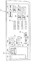
次に、図11を参照して孔版印刷装置200の主な制御構成を説明する。
図11において、制御装置100は、孔版印刷装置200の主として原稿読取動作、製版動作、給紙動作および印刷動作を制御する。制御装置100は、CPU101(中央演算処理装置)、図示しないI/O(入出力)ポート、ROM102(読み出し専用記憶装置)、電池付きのRAM103(読み書き可能な記憶装置)および図示しない電池付きのタイマ等を備え、それらが図示しない信号バスによって接続された構成を有するマイクロコンピュータを具備している。
【0100】
制御装置100は、図1にも示すように、本体フレーム130内の制御基板配置部に設けられている。この制御基板配置部には、図11に示すように、画像センサ147から送信されるアナログの画像信号をA/D変換するA/D変換部150と、A/D変換部150を経由して送信されるデジタルの画像信号データを処理する画像信号処理部151と、画像信号処理部151から送信されるデジタルの画像信号データを記憶するビットマップメモリからなる画像メモリ152と、サーマルヘッド11を駆動制御するサーマルヘッド駆動回路(図示せず)を含むサーマルヘッド駆動制御部153とが配設されている。
【0101】
制御装置100のCPU101(以下、説明の簡明化を図るため、単に「制御装置100」というときがある)は、上記入力ポートやセンサ入力回路等を介して、画像信号処理部151と、操作パネル80の上記した各種キーとそれぞれ電気的に接続されていて、画像信号処理部151からのデータ信号や上記各種キーからのオン/オフ信号を受信する。また、制御装置100は、上記入力ポートやセンサ入力回路等を介して、版胴センサ19と、第1用紙センサ33と、第2用紙センサ34と、排紙センサ39と、用紙サイズ検知センサ群117と、原稿サイズ検知センサ群149と、給紙レジストセンサ120とそれぞれ電気的に接続されていて、上記各センサ19,33,34,39,117,149,120からのオン/オフ信号やデータ信号を受信する。
【0102】
制御装置100は、上記出力ポートおよび液晶駆動回路や発光ダイオード駆動回路、モータ駆動回路、ソレノイド駆動回路等を介して、画像信号処理部151と、操作パネル80の液晶表示部85や各種表示器と、マスタ搬送モータ10Aと、メインモータ17と、給紙モータ45と、レジストモータ50と、第1ソレノイド62と、第2ソレノイド77とそれぞれ電気的に接続されていて、各種の指令信号を画像信号処理部151、液晶表示部85や各種表示器、上記各モータ10A,17,45,50や各ソレノイド62,77にそれぞれ送信する。
【0103】
本実施形態では、制御装置100は、以下の制御機能を有する。
第1に、制御装置100は、上記印刷モード切換手段からの第1の印刷モード設定に係る信号に基づいて、第1の製版処理を行うようにサーマルヘッド駆動制御部153を介してサーマルヘッド11を制御し、かつ、第1の製版処理をされたマスタ8を巻装した版胴1の1回転中に給紙ローラ35が1枚の用紙38を送り出すように給紙モータ45を制御した後、レジストローラ対31,32が版胴1上の第1の製版処理をされたマスタ8における製版画像の位置にタイミングを合わせて1枚の用紙38を給送するようにレジストモータ50を制御し、なおかつ、印刷中に排紙センサ39により印刷された用紙38の先端が検知されないときその信号に基づいて、緊急押圧解除手段を作動させる、すなわち解除カム67が駆動されるように解除カム駆動手段(第2ソレノイド77等)を制御する第1の制御手段としての制御機能を有すると共に、係止手段64の第1ソレノイド62をオフするように制御する制御機能を有する。
【0104】
第2に、制御装置100は、第2の印刷モード設定キー96からの第2の印刷モード設定に係る信号および同一画像製版モード設定キー97からの同一画像製版モード設定に係る信号に基づいて、版胴1の回転方向に沿って1版のマスタ8に分割された複数の同一製版画像を製版・形成するようにサーマルヘッド駆動制御部153を介してサーマルヘッド11を制御し、かつ、版胴1の1回転中に版胴1上のマスタ8における複数の同一製版画像に対応して給紙ローラ35が複数枚の用紙38を順次送り出すように給紙モータ45を制御した後、レジストローラ対31,32が版胴1上のマスタ8における複数の同一製版画像の位置ごとにタイミングを合わせて複数枚の用紙38を連続的に順次給送するようにレジストモータ50を制御する第2の制御手段としての制御機能を有する。
【0105】
第3に、制御装置100は、第2の印刷モード設定キー96からの第2の印刷モード設定に係る信号および異種画像製版モード設定キー98からの異種画像製版モード設定に係る信号に基づいて、版胴1の回転方向に沿って1版のマスタ8に分割された複数の異種製版画像を製版・形成するようにサーマルヘッド駆動制御部153を介してサーマルヘッド11を制御し、かつ、版胴1の1回転中に版胴1上のマスタ8における複数の異種製版画像に対応して給紙ローラ35が複数枚の用紙38を順次送り出すように給紙モータ45を制御した後、レジストローラ対31,32が版胴1上のマスタ8における複数の異種製版画像の位置ごとにタイミングを合わせて複数枚の用紙38を連続的に順次給送するようにレジストモータ50を制御する第2の制御手段としての制御機能を有する。
【0106】
第4に、制御装置100は、第2または第3の制御機能に付加して、第1用紙センサ33、第2用紙センサ34および排紙センサ39のうちの少なくとも1つのセンサにより用紙38の先端が検知されないときその出力信号に基づいて、緊急押圧解除手段を作動させる、すなわち解除カム67が駆動されるように解除カム駆動手段(第2ソレノイド77等)を制御する第3の制御手段としての制御機能を有すると共に、係止手段64の第1ソレノイド62をオフするように制御する制御機能も有する。
【0107】
第5に、制御装置100は、用紙サイズと1版のマスタ8に製版・形成されるべき製版画像または複数の同一製版画像または複数の異種製版画像のサイズとが合っているか否かを判断し、用紙サイズと製版画像または複数の同一製版画像または複数の異種製版画像のサイズとが合っていないとき、液晶表示部85のメッセージ表示部86および絵表示部87にその旨の表示(報知)をさせる第4の制御手段としての制御機能を有する。これに加えて、ユーザが所望する印刷物だけを確実に得るようにする上からは、メインモータ17の回転駆動を禁止したり給紙モータ45の回転駆動を禁止したりすることにより印刷動作等を禁止する制御機能を制御装置100に付加してもよい。
【0108】
制御装置100の第5の制御機能において、制御装置100は、用紙サイズに係る情報および1版のマスタに製版・形成されるべき製版画像のサイズに係る情報を、以下の各種検知手段および各種設定手段の2つの手段の組み合わせにより出力される信号に基づいて認識する。すなわち、第1の組み合わせは1版のマスタ8に形成されるべき製版画像または複数の同一製版画像または複数の異種製版画像のサイズを検知する画像サイズ検知手段と用紙サイズ検知センサ群117とであり、第2の組み合わせは上記画像サイズ検知手段と用紙サイズ設定手段90とであり、第3の組み合わせは1版のマスタ8に形成されるべき製版画像または複数の同一製版画像または複数の異種製版画像のサイズを設定する画像サイズ設定手段と用紙サイズ検知センサ群117とであり、第4の組み合わせは上記画像サイズ設定手段と用紙サイズ設定手段90との組み合わせである。
【0109】
第6に、制御装置100は、上記各種キーを押したことにより生成される出力信号に基づいて、その機能やモードが設定された結果として発光ダイオード駆動回路を介して上記各LEDを点灯・表示させる制御機能も有する。
【0110】
ROM102には、CPU101の上記諸制御機能を発揮させるための後述する動作順序を表したフローチャートに係るプログラムや、関係データ等が予め記憶されている。ROM102には、給紙モータ45の回転駆動により給紙ローラ35の配置位置(分離部材とのニップ部中心)から第1用紙センサ33の配置位置(用紙38の先端を検知できる位置)までの用紙搬送経路XAの一定の距離について、用紙38が搬送される所定の時間や給紙モータ45に供給される所定のパルス数に関する関係データ、レジストモータ50の回転駆動によりレジストローラ対31,32の配置位置(ニップ部中心)から第2用紙センサ34の配置位置(用紙38の先端を検知できる位置)までの用紙搬送経路XAの一定の距離について、用紙38が搬送される所定の時間やレジストモータ50に供給される所定のパルス数に関する関係データ、および第2用紙センサ34の配置位置(用紙38の先端を検知できる位置)から排紙センサ39までの用紙搬送経路XAの一定の距離について、用紙38が搬送される所定の時間に関する関係データが予め記憶されている。
【0111】
上記各所定の時間や上記各パルス数は、厳密には給紙条件(用紙種類、用紙サイズや両面印刷における片面印刷済みの用紙使用等の組み合わせ)に応じて、給紙ローラ35および分離部材36であるいはレジストローラ対31,32で用紙38のスリップ量がそれぞれ異なることに着目して、上記給紙条件(用紙種類、用紙サイズや両面印刷における片面印刷済みの用紙使用等の組み合わせ)に対応して予め実験等によって設定しておくことが好ましい。
上記プログラムや関係データの変更は、PROM(プログラマブルROM)としたり、ROM102のチップ交換によって変更したりしてもよい。
【0112】
RAM103は、CPU101での判断結果や計算結果を一時記憶したり、上記各センサ、上記各設定手段や上記検知手段等からの出力信号等を随時記憶したりしてこれら信号の入出力を行う。上記タイマは、給紙モータ45の起動時点から第1用紙センサ33のオン信号出力時点までの、レジストモータ50の起動時点から第2用紙センサ34のオン信号出力時点までの、および第2用紙センサ34のオン信号出力時点から排紙センサ39のオン信号出力時点までの時間等を計時する計時手段としての機能を有する。
上記タイマの計時機能に代えて、給紙モータ45の起動時点からの同モータ45に供給され入力されるパルス数を計数したり、レジストモータ50の起動時点から同モータ50に供給され入力されるパルス数を計数したりするパルス数計数手段としての機能を制御装置100のCPU101に付与してもよい。
【0113】
ここで、後述する動作を理解しやすいように、第1の製版処理および第1の印刷モードと比較した態様での、第2の製版処理および第2の印刷モードの具体例を挙げて説明しておく。
【0114】
本実施形態では、マスタ8に形成される複数の製版画像の面数に応じて用紙38の給送枚数を設定できるようになっている。特に、マスタ8のサイズに対して用紙サイズが小さい場合に、そのマスタ8に複数面の製版画像が形成されたときには、制御装置100からの指令により複数面の製版画像ごとに給紙ローラ35が複数枚の用紙38を連続的に順次送り出すように給紙モータ45が制御された後、レジストローラ対31,32が複数面の製版画像の位置ごとにタイミングを合わせて複数枚の用紙38を連続的に順次給送するようにレジストモータ50が制御される。
【0115】
第1の製版処理とは、上述したように、サーマルヘッド11が1版のマスタ8に対して1枚の用紙38を対象とした製版画像を形成する製版処理動作であり、従来の孔版印刷装置等に搭載されている製版装置や製版給版装置によって実行される通常の製版動作と同じものである。同様に、第1の印刷モードとは、第1の製版処理されたマスタ8を巻装した版胴1の1回転中に1枚の用紙38を対応させて印刷する印刷動作であり、従来の孔版印刷装置によって実行される通常の印刷動作と同じものである。
【0116】
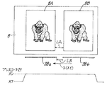
これに対して、第2の製版処理は、図13に具体的な一実施例として示したように、サーマルヘッド11が1版のマスタ8に対して複数枚(以下、実施例的には2枚とする)の用紙38を対象とし版胴1の回転方向に沿って分割された複数(以下、実施例的には2面とする)の製版画像を形成する製版処理動作である。
【0117】
図13において、1版のマスタ8の左端側が版胴1のクランパ7で係止・固定される先端余白部である。1版のマスタ8のサイズとしては、一実施例的に言えば、例えばA3サイズ(すなわち、マスタ搬送方向X1(用紙搬送方向X)の長さで例えば530mm、その幅方向の長さで例えば320mm)を用いているものとして説明する。符号8Aは第2の製版処理の実行によって1版のマスタ8に形成される第1面の製版画像(以下、「第1面製版画像」という)を、符号8Bは第2面の製版画像(以下、「第2面製版画像」という)を表している。図13に例示されているとおり、第1面製版画像8Aおよび第2面製版画像8Bは、1枚の原稿133の画像情報に基づいて図11に示す画像信号処理部151およびサーマルヘッド駆動制御部153を介してサーマルヘッド11を駆動させて、版胴1の回転方向に沿って1版のマスタ8に分割された2面の同一製版画像を形成する同一画像製版モードを設定する同一画像製版モード設定キー97の押下によって設定できる。
【0118】
図示を省略しているが、互いに異なる異種の第1面製版画像および第2面製版画像は、例えば2枚の原稿133の画像情報に基づいて図11に示す画像信号処理部151およびサーマルヘッド駆動制御部153を介してサーマルヘッド11を駆動させて、版胴1の回転方向に沿って1版のマスタ8に分割された2面の異種製版画像を形成する異種画像製版モードを設定する異種画像製版モード設定キー98の押下によって設定できる。
【0119】
このように、第2の製版処理では、同一画像製版モード設定キー97または異種画像製版モード設定キー98を押下することにより、同一画像製版モードおよび異種画像製版モードの何れか一方を選択することができる。それ故に、同一画像製版モードを選択した場合には、例えば同じ原稿133の画像情報に基づいて連続して2枚の用紙38に印刷することで印刷時間を短縮することができるし、異種画像製版モードを選択した場合には、例えば2枚の原稿133の画像情報に基づいて、1版のマスタ8を用いて一度に2頁分の印刷を行えることになる。
【0120】
実施例的に上述したように、第1の印刷モードが設定されたときには、1版のマスタ8に対して1枚の用紙38への印刷が実行され、第2の印刷モードが設定された場合には、1版のマスタ8に対して2枚の用紙38への印刷が実行される。第2の印刷モードが設定されたときの本発明の実施例としては、勿論上記した例に限らず、3枚以上の用紙38を対象とした第2の製版処理動作も可能であり、最大サイズのマスタ8に対して3枚以上に分割した態様で用いられる用紙38のサイズのときには、その分割数に応じた製版画像の形成が行えるものである。
【0121】
第2の印刷モードが設定されたときに印刷に使用される用紙サイズの具体例としては、例えばA4サイズ(横、すなわち用紙搬送方向Xの長さで210mm、その幅方向の長さで297mm)を用いるものとして説明する。なお、用紙搬送方向Xは、図13や図14に括弧を付して示したように、用紙搬送方向Xと平行なマスタ搬送方向X1および平面図的に展開した版胴1の回転方向でもある。
【0122】
図13において、版胴1上に巻装される1版(1つ)のマスタ8に対して複数面の製版画像例として示されているように、1版の製版済みのマスタ8に形成された複数面の製版画像に対するレジストローラ対31,32による用紙38の用紙給送モードの態様としては、例えば、1版のマスタ8(例えばA3サイズ)に対して用紙搬送方向Xで前方(下流側)に位置する第1面製版画像8Aと、後方(上流側)に位置する第2面製版画像8Bとを所定の間隔LAをもって製版・形成し、その第1面製版画像8Aに対応して給送される先行する1枚目の用紙38a(図13の左側の用紙38であり、以下、「先行用紙38a」という。例えばA4サイズ)と第2面製版画像8Bに対応して給送される後続する2枚目の用紙38b(図13の右側の用紙38であり、以下、「後続用紙38b」という。例えばA4サイズ)を所定の間隔LBをもって所定のタイミングを取って給送する態様である(LA>LB)。
この場合、上述したとおり、2面の製版画像8A,8B同士が同じ内容のものであるときには版胴1の1回転中に2枚の用紙38(先行用紙38aおよび後続用紙38b)への印刷が行え、異なる内容のものであるときには版胴1の1回転中に原稿2頁分の印刷が行えることになる。
【0123】
版胴1上に巻装された1版のマスタ8に形成する第1面製版画像と第2面製版画像とのマスタ搬送方向X1における種々の間隔LAに対する間隔LBについての2枚の用紙38a,38bの用紙給送モードの態様としては、図13に示した以外に、例えば図13に示した第1面製版画像8Aと第2面製版画像8Bとのマスタ搬送方向X1における所定の間隔LAよりもそれを詰めて製版すると共に、図13に示した2枚の用紙38の所定の間隔LBよりもそれを詰めて給送してもよい。この場合の用紙給送モードの態様は、第1面製版画像8Aに対応して給送される先行用紙38aの搬送速度よりも、第2面製版画像8Bに対応して給送される後続用紙38bのそれを所定時間だけ速めて給送する態様である。
【0124】
上記したと別の用紙給送モードの態様としては、例えば図13に示した第1面製版画像8Aと第2面製版画像8Bとのマスタ搬送方向X1における所定の間隔LAよりもそれをさらに詰めて製版すると共に、図13に示した先行用紙38aと後続用紙38bとの所定の間隔LBを無くして一部重なるように、給送してもよい。この場合、第1面製版画像8Aに対応して送り出された先行用紙38aの搬送速度よりも、第2面製版画像8Bに対応して給送される後続用紙38bのそれをさらに速めて、すなわち給送タイミングを速めて先行用紙38aと後続用紙38bとの一部が重なるように給送する態様である。
【0125】
先行用紙38aおよび後続用紙38bを含めた用紙38の給送タイミングは、レジストローラ対31,32(正確にはレジストローラ下32)の回転開始時機、すなわちレジストモータ50の回転駆動開始時機(起動時機)によって設定されるようになっている。
【0126】
レジストローラ対31,32による用紙38の給送開始から給送完了までは、レジストローラ下32を回転駆動するレジストモータ50の回転量、つまりレジストモータ50として用いられているステッピングモータのステップ数および第2用紙センサ34による用紙38の先端検知および後端検知により、また版胴センサ19による版胴1の回転量検知を参照して制御装置100で判断される。また、給紙ローラ35による用紙38の送り出し開始から送り出し完了までは、給紙ローラ35を回転駆動する給紙モータ45の回転量、つまり給紙モータ45として用いられているステッピングモータのステップ数および第1用紙センサ33による用紙38の先端検知および後端検知により、また版胴センサ19による版胴1の回転量検知を参照して制御装置100で判断される。版胴1とプレスローラ21との圧接による用紙38への印刷開始から印刷完了までは、メインモータ17の回転量、つまり給紙レジストセンサ120および版胴センサ19による版胴1の印刷開始時機およびその回転量検知により、制御装置100で判断される(図15参照)。
【0127】
図12のタイミングチャートおよび図13において、1版のマスタ8に対して第1面製版画像8Aおよび第2面製版画像8Bを所定の間隔LAをもって形成した場合に、第1面製版画像8Aおよび第2面製版画像8Bに対応して2枚の用紙38a,38bを所定の間隔LBをもって所定の給送タイミングを取って給送する内容が示されている。
給紙ローラ35の回転(オン)により第1面製版画像8Aに対応して先行用紙38aが送り出されると、第1面製版画像8Aとのレジストタイミングを取ってレジストローラ下32が回転を開始(オン)されることにより先行用紙38aが版胴1に向けて給送され、次いで、所定時間経過後に第2面製版画像8Bに対応して、第1面製版画像8Aの場合と同様に後続用紙38bの送り出し・給送が連続して行われる。
【0128】
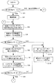
次に、制御装置100による制御の下になされる動作について説明する。
(動作例1)
まず、図1ないし図11、図16および図17を参照して、動作例1について説明する。この動作例1は、図16および図17に示すフローチャートに第1の印刷モードに係る動作として表されている。図17に示すステップS16以外は従来の孔版印刷装置に係る動作と同様であるため、ステップS1における第1の印刷モードの設定から版付け動作に至るまでの細部動作の図示はステップS2における製版処理を除き省略している。動作例1では、第1の印刷モードに係る動作を理解しやすくするために、実施例的に原稿サイズ検知センサ群149と用紙サイズ検知センサ群117とが使用されると共に、マスタサイズとしてA3のものが、原稿サイズおよび用紙サイズとして、それぞれA3サイズのものが用いられるものとする。
【0129】
先ず、ユーザが上記電源スイッチをオンすると、第1の印刷モードが自動的に設定されて、第1の印刷モード設定表示ランプ95が点灯する(ステップS1参照)。次いで、ADF148の原稿受け台134にA3サイズの原稿133がセットされ、これに前後して印刷に使用する用紙サイズとしてA3サイズの用紙38を給紙トレイ37上に補充積載する。このとき、用紙サイズ検知センサ群117により、給紙トレイ37上に積載された用紙38の用紙サイズとしてA3サイズが自動的に検出され、その信号が制御装置100へ送信されRAM103に記憶される。
なお、給紙トレイ37上に所定の用紙サイズの用紙38が積載収容されていないときや用紙38が無いときには、操作パネル80における液晶表示部85のメッセージ表示部86および絵表示部87にその旨の警告表示がなされる。
【0130】
次いで、操作パネル80の製版スタートキー81が押されると製版スタート信号が生成されて、これが制御装置100に入力されることによって排版から排紙に亘る一連の動作が自動的に行われる。最初に排版動作と並行して製版動作が行われるが、これに先後して、上記給紙トレイ昇降モータがオンすることにより給紙トレイ37が上昇して、最上の用紙38が給紙ローラ35に当接することにより、図示しない給紙位置検知センサのオン検知によって最上の用紙38が給紙可能な状態になったことが制御装置100により判断されると、給紙装置30では給紙待機状態となる。
【0131】
メインモータ17が回転駆動されることにより版胴1が回転し、上記排版装置により、版胴1に巻装されている使用済みのマスタ8が剥離され上記排版箱に搬送・排出される。次いで、版胴1はクランパ7が図1において略右真横位置となる給版位置まで回転して停止し、クランパ7が上記開閉装置により開放されて給版待機状態となる。
【0132】
版胴1が給版位置で停止するのに前後して上記排版動作と並行して、原稿読取装置20のADF148が作動することにより1枚の原稿133が読取部であるコンタクトガラス135上に送出されると、スキャナ装置132の作動によってその原稿133の画像が光学情報として読み取られる。この時、原稿サイズ検知センサ群149により、原稿受け台134上にセットされた原稿133の原稿サイズとしてA3サイズが自動的に検出され、その信号が制御装置100へ送信される。さらに、読み取られた原稿反射の光学情報は、画像センサ190によってアナログの電気信号に変換される。そのアナログの電気信号はA/D変換部150でデジタル信号に変換された後に、画像信号処理部151を介して、デジタル画像信号データとして画像メモリ152に一度記憶される。画像信号処理部151は、画像メモリ152に記憶格納されている製版すべき画像情報としてのデジタル画像信号データを順次呼び出しながら、版胴1に巻装される1枚のマスタ8としての1版のマスタ8に形成されるべき製版画像に対応した画像情報の画像領域を検知・認識し、その画像領域に係る信号を制御装置100へ送信する。ここで、画像領域とは、マスタ8に形成されるべき製版画像に対応した画像情報の最外縁部の大きさを意味する。
【0133】
ここで、制御装置100は、用紙サイズと1版のマスタ8に形成されるべき製版画像のサイズとが合っているか否かを判断する。ここでは、用紙サイズと1版のマスタ8に形成されるべき製版画像のサイズとが合っているので、問題なく動作が進行する。しかし、用紙サイズと製版画像のサイズとが合っていないときや、用紙サイズと、上記変倍率設定キーで設定した変倍率によって変倍された製版画像のサイズとが合わないと制御装置100が判断・認識するとき、制御装置100からの指令によって液晶表示部85のメッセージ表示部86および絵表示部87にその旨の警告表示がなされる。
ユーザはメッセージ表示部86および絵表示部87の警告表示内容を見て、適切な用紙サイズの用紙38を選択・積載したり、上記変倍率設定キーで適切な変倍率に変更する操作等を行うこととなる。
【0134】
上記動作と同時的に、画像信号処理部151は、サーマルヘッド11の上記発熱素子を発熱駆動制御するためのデジタル画像信号をサーマルヘッド駆動制御部153へ送信する。
ステップS2において、サーマルヘッド駆動制御部153より送出されるデジタル画像信号によって、サーマルヘッド11の上記多数の発熱素子が主走査方向にパルス状に通電されて選択的に発熱されると共に、マスタ搬送モータ10Aが回転駆動されることにより、プラテンローラ10、搬送ローラ対12,12および反転ローラ対14,14が回転を開始して、マスタロール8aからマスタ8が引き出されつつマスタ搬送方向X1に搬送されながら、マスタ8の上記熱可塑性樹脂フィルム部分が画像情報に応じて選択的に加熱穿孔される製版が行われる。この製版初期時から版胴1への製版済みのマスタ8の給版時(後述する)までは、反転ローラ対14,14の上記電磁クラッチはオンされていて、マスタ搬送モータ10Aの回転駆動力が反転ローラ対14,14に伝達される状態にある。
【0135】
そして、マスタ8の先端部がガイド板15に案内されてステージ6に対して拡開しているクランパ7の間に挿入され、反転ローラ対14,14等が所定の角度回転して、これに対応してマスタ搬送モータ10Aのステップ数がある設定値に達し、製版済みのマスタ8の先端部がステージ6とクランパ7との間に届いたと判断されると、上記開閉装置によりクランパ7が閉じられ、製版済みのマスタ8の先端部がステージ6とクランパ7との間に吸着・挾持される。
【0136】
製版済みのマスタ8の先端部のクランプ後、メインモータ17の回転駆動により版胴1が回転を再開して、製版済みのマスタ8が反転ローラ対14,14により搬送されて版胴1の外周面へ巻装されるべく給版されるが、この版胴1の外周面への巻装時には巻装シワを発生させることなく行われる。
この時、上記電磁クラッチがオフすることにより、版胴1の回転力によってマスタ8を介して反転ローラ対14,14が連れ回り・従動回転することとなるので、マスタ8に適度な張力が作用して巻装シワの発生をより確実に防止することができる。
【0137】
マスタ搬送モータ10Aの所定ステップ数の回転駆動により、マスタ8への製版および設定量の製版済みのマスタ8の搬送が終了したと判断されると、カッタ13が作動して製版済みのマスタ8が切断されると共に、マスタ搬送モータ10Aの回転駆動が停止されることによりプラテンローラ10、搬送ローラ対12,12および反転ローラ対14,14の回転が停止する。
【0138】
そして、切断された製版済みのマスタ8の後端が、版胴1の回転によって製版装置16内から引き出され、版胴1の外周面に完全に巻き取られた段階で版胴1への製版済みのマスタ8の巻装が終了する。ここで、製版済みのマスタ8の版胴1の外周面への巻装長さは、プレスローラ21がマスタ8の後端より外れて版胴1における開口部1aの後部領域に対して押圧することによるプレスローラ21の汚れを防止するために、版胴1から離間する点よりもやや長目に設定されている。
【0139】
版胴1への製版済みのマスタ8の巻装が完了すると、版胴1が所定の周速度で図1に示す矢印方向に回転し始めることにより、給紙・印刷工程が開始される。なお、用紙38の先端が第2用紙センサ34を横切り・通過するまでは、換言すれば第2用紙センサ34により用紙38の先端がオン検知されるまでは、制御装置100によって係止手段64の第1ソレノイド62がオフされたままに制御されているため変位手段29は非作動状態にあり、これによりプレスローラ21は非印刷位置、すなわち版胴1の外周面から離間した初期位置で保持されている。説明の都合上から、給紙・印刷・排紙動作については、不送りやジャムあるいは用紙38の巻き上がり等が発生しない正常に印刷される場合の動作を始めに説明する(図16および図17に示すフローチャートのステップS3ないしステップS13参照)。
【0140】
版胴1が矢印方向に回転して、先ず、図5に示した給紙開始用遮光板121が給紙レジストセンサ120と係合することにより、給紙レジストセンサ120がオンして給紙スタート信号が生成され、この信号がトリガとなって給紙モータ45が起動(回転駆動開始)する。給紙モータ45が図6において時計回りに回転駆動されることにより、給紙モータプーリ46、給紙モータベルト48、給紙ローラプーリ47および上記ワンウェイクラッチを介して、給紙ローラ軸35aおよび給紙ローラ35が時計回りに回転することで、給紙ローラ35と接触している給紙トレイ37上の最上の用紙38が、搬送されながら分離部材36との協働作用によって1枚に分離されて用紙搬送方向Xの下流側であるレジストローラ対31,32のニップ部に向けて給送される(ステップS3およびステップS4参照)。
【0141】
図1において、給紙ローラ35の回転により用紙38の先端がレジストローラ対31,32のニップ部に向けて正常に給送され、すなわち用紙38の先端が、上記タイマで計時される所定の時間内(あるいは給紙モータ45に供給される所定のパルス数内、以下、この括弧内の記載を省略する)に第1用紙センサ33により検知されて第1用紙センサ33がオン(以下、「オン検知」という)し、この信号が制御装置100に入力される。この後、制御装置100からの指令に基づき、給紙モータ35は所定のパルス数(所定のステップ数)分回転した後停止する。
この時、レジストローラ接離手段40におけるレジストカム43の版胴1の回転に同期した所定の回転・タイミングによって、レジストローラ上31が下降してレジストローラ下32に当接することで、所定のニップ部が形成される。
【0142】
用紙38は、給紙モータ35が停止するまでの間、第1用紙センサ33で検知された位置から所定ステップ数分送られることによって、レジストローラ対31,32のニップ部で用紙38の先端が当接した後、用紙38の先端部に所定の湾曲した撓みが形成された状態で保持される。
【0143】
ここで、用紙38が正常に送り出されたことは、次のことに基づく。すなわち、給紙ローラ35の配置位置(分離部材とのニップ部中心)から第1用紙センサ33の配置位置(用紙38の先端を検知できる位置)までの用紙搬送経路XAの距離は一定であるため、給紙ローラ35の回転速度(周速度、換言すれば用紙38の搬送速度でもある)を一定とし、かつ、用紙38が正常に送り出されたとすれば上記距離について用紙38が搬送されるに要する時間あるいは給紙モータ45に供給されるパルス数も所定の時間内あるいはパルス数内となる(ステップS5およびステップS6参照)。
【0144】
次いで、版胴1が図1における矢印方向にさらに回転して、レジスト開始用遮光板122が給紙レジストセンサ120と係合することにより、給紙レジストセンサ120がオンしてレジストスタート信号が生成され、この信号がトリガとなってレジストモータ50が起動(回転駆動開始)する。レジストモータ50が図6において反時計回りに回転駆動され、レジストモータプーリ51、レジストモータベルト53およびレジストローラプーリ52を介して、レジスト下軸32aおよびレジストローラ下32が反時計回りに回転することで、レジストローラ対31,32のニップ部で当接して待機している用紙38の先端が、レジストローラ上31とで押圧されながら給送され、版胴1とプレスローラ21との間に向けて送り出される(ステップS7およびステップS8参照)。
【0145】
次いで、ステップS9において、レジストローラ対31,32により給送された用紙38の通過が正常に行われ、すなわち用紙38の先端が、上記タイマで計時される所定の時間内(あるいはレジストモータ50に供給される所定のパルス数内、以下、この括弧内の記載を省略する)に第2用紙センサ34によってオン検知されることによって、この信号が制御装置100に入力される。そして、制御装置100からの指令に基づき係止手段64の第1ソレノイド62に通電がなされ、第1ソレノイド62がオンすることにより変位手段29を作動させる。
【0146】
ここで、用紙38が版胴1とプレスローラ21との間に向けて正常に送り出されたことは、次のことに基づく。すなわち、レジストローラ対31,32の配置位置(ニップ部中心)から第2用紙センサ34の配置位置(用紙38の先端を検知できる位置)までの用紙搬送経路XAの距離は一定であるため、レジストモータ50の回転速度(周速度、換言すれば用紙38の搬送速度でもある)を一定とし、かつ、用紙38が正常に給送されたとすれば上記距離について用紙38が給送されるに要する時間あるいはレジストモータ50に供給されるパルス数も所定の時間内あるいはパルス数内となることに基づく。
【0147】
第1ソレノイド62がオンすることで、プランジャ62aが吸引され、これにより係止部材60が引張バネ63の付勢力に抗して支軸61を中心に反時計回りに揺動し、係止部材60の係止爪60aに切欠23aを係止させている加圧アーム23の他端部側は、その係止を解除されて加圧バネ25の付勢力によってアーム軸22aを中心に時計回りに揺動する。加圧アーム23の他端部側の揺動により、カムフォロア24の外周面が印圧カム27の輪郭周面と当接し、カムフォロア24の外周面が印圧カム27の小径部周面と対向し非当接状態となる印圧カム27の回転位置で、プレスアーム対22,22はアーム軸22aを中心に加圧バネ25の付勢力によって時計回りに揺動し上昇することとなる。
これにより、プレスローラ21は、その外周面が版胴1上の製版済みのマスタ8に用紙38を押し付ける印刷位置に変位して、プレスローラ21は従動回転しながら版胴1上の製版済みのマスタ8に用紙38を連続的に押し付けることで、製版済みのマスタ8を版胴1の外周面に密着させそれにインキを充填させるためのいわゆる版付けが行われる。この版付けでは、版胴1の開口部1aの開孔部分から製版済みのマスタ8の穿孔部分へとインキが滲み出てきて用紙38の表面に転移されることで孔版印刷が行われる。
【0148】
この時、インキローラ2も版胴1の回転方向と同一方向に回転する。インキ溜まり4のインキは、インキローラ2の回転によりインキローラ2の表面に付着され、インキローラ2とドクターローラ3との間隙を通過する際にその量を規制され、版胴1の内周面に供給される。
またこの時、レジストローラ接離手段40におけるレジストカム43の所定の回転・タイミングによって、レジストローラ上31は、版胴1の所定の回転位置でレジストローラ下32から上昇して離間すると共に、レジストモータ50も所定のパルス数(所定のステップ数)分回転駆動された後停止する。
【0149】
なお、版胴1が図1中矢印方向に回転して、クランパ7が版胴1に圧接しているプレスローラ21の近傍に至ると、版胴1の回転と同期して回転駆動されていた印圧カム27が、その大径部周面をカムフォロア24の外周面に接する位置に回転させているので、プレスローラ21は版胴1の外周面から外側へ突出しているクランパ7から離間することとなり、プレスローラ21とクランパ7部位との干渉が避けられる。
【0150】
そして、版付け・孔版印刷された用紙38はプレスローラ21で押圧された状態で版胴1の図1中矢印方向の回転によってさらに搬送され、その用紙38の先端および後端が排紙センサ39によりオン検知されると、版胴1上の製版済みのマスタ8に巻き上がることなく正常に搬送されたと制御装置100により判断される(ステップS10ないしステップS12参照)。
【0151】
こうして版付け・孔版印刷された用紙38の先端部は、版胴1の外周面に接近する剥離爪55により版胴1上の製版済みのマスタ8から剥離され、剥離された用紙38は排紙トレイ59に排出・積載される。
一方、プレスローラ21が版胴1の外周面に当接した時点より版胴1が略4分の3周し、印圧カム27の大径部周面とカムフォロア24とが接する時点、つまり、係止部材60の係止爪60aと加圧アーム23の切欠23aとが係止可能な時点において、制御装置100からの指令により第1ソレノイド62への通電が遮断(オフ)される。すると、係止部材60は、引張バネ63の付勢力により支軸61を中心として時計回りに揺動され、その係止爪60aに加圧アーム23の切欠23aが係止される。これにより、プレスローラ21は、版胴1の外周面から離れた非印刷位置(初期位置)に復帰して保持されて、印刷待機状態となる。
【0152】
また、給紙ないしは版付け中において、プラテンローラ10、搬送ローラ対12,12および反転ローラ対14,14が回転を再開して、切断されたマスタ8の先端が反転ローラ対14,14のニップ部に向けて送り込まれる。マスタ搬送モータ10Aのパルス数から、切断されたマスタ8の先端が反転ローラ対14,14のニップ部に届き挟持されたと判断されると、プラテンローラ10、搬送ローラ対12,12およびおよび反転ローラ対14,14の回転が停止し、次の製版に備えた製版待機状態になる。
【0153】
版付け終了後、ユーザは排紙トレイ59に排出された印刷物を適宜目視して、通常の印刷動作を行ってもよいかどうかを適宜判断し、オーケーであればテンキー83で印刷枚数を設定し、印刷スタートキー82を押すと、上記したと同様の給紙、通常印刷および排紙の各動作がテンキー83で設定された設定枚数分について順次行われる。なお、版付けされた用紙38の枚数は、正規の通常の印刷枚数としてカウントされないようになっている(ステップS13参照)。
通常の印刷動作は、版付け時の印刷動作と比較して、上記したように版付け印刷に用いられた用紙38の枚数が正規の通常の印刷枚数としてカウントされないこと、およびユーザが所望する設定印刷速度に応じた速度での給紙、印刷および排紙の各動作が行われることが主に相違するだけである。
【0154】
次に、図16および図17のフローチャートを参照しながら、給紙・印刷・排紙動作について、不送りやジャムあるいは用紙38の巻き上がり等が発生した場合の異常動作を説明する。
【0155】
上述したと同様にステップS1からステップS4に至る動作が行われて、版胴1が所定の位置に回転した時に、給紙モータ45の起動を介しての給紙ローラ35の回転により、用紙38の先端がレジストローラ対31,32のニップ部に向けて送り出されたにも拘らず、用紙38の先端が、上記タイマで計時される所定の時間内に第1用紙センサ33により検知されなかった場合には、制御装置100は第1用紙センサ33の配置位置よりも用紙搬送経路XAの上流側に用紙38が留まっていると判断して、第1ソレノイド62をオフしたままでのプレスローラ21の上昇をロック、すなわちプレスローラ21が非印刷位置を占めたままでの印圧解除状態が保持される(ステップS5およびステップS14参照)。
【0156】
そして、上記したプレスローラ21の上昇がロックされた直後のステップS15において、制御装置100からの指令により操作パネル80のメッセージ表示部86に用紙38の搬送ミス・ジャムの警告表示がなされると共に、絵表示部87にその搬送ミス・ジャムの発生箇所が点灯もしくは点滅表示され、これと同時にメインモータ17等の回転駆動が停止する。
【0157】
ユーザは、メッセージ表示部86に表示された排紙ミス・ジャム警告表示および絵表示部87に表示された排紙ミス・ジャム発生箇所を視認した上、給紙装置30配置箇所のフロントカバー等を開けてジャム紙の除去作業等を行う。ジャム用紙除去後、ステップS3からの再スタートとなる。
【0158】
次に、ステップS3からステップS8までの動作が上記した正常の動作と同様に行われた場合、すなわち上記タイマで計時される所定の時間内に用紙38の先端が第1用紙センサ33で検知され、その後の動作がステップS8まで正常に行われた場合には、以下のようになる。つまり、レジストローラ対31,32の回転により給送されたはずの用紙38の先端が第2用紙センサ34により検知されなかった場合には、用紙38の先端の位置について2つの場合が想定される。
【0159】
すなわち、用紙38の先端が第1用紙センサ33により検知されているにも拘らずレジストローラ対31,32のニップ部まで届いていないためにレジストローラ対31,32で給送されなかった第1の場合と、レジストローラ対31,32で給送されたが同ニップ部でのスリップ量の過大等によって、第2用紙センサ34の配置位置(用紙38の先端が検知できる位置)まで給送されなかった第2の場合とが想定される。この2つの場合の何れかであるかは、レジストローラ対31,32に特別の検出手段等を配設しない限り判別できないので、以下区別せずに同様の給送不良として扱う。
【0160】
ステップS9において、所定の時間内に第2用紙センサ34によって用紙38の先端がオン検知されなかった場合には、制御装置100は第1用紙センサ33の配置位置(用紙38の先端が検知できる位置)よりも下流側であって第2用紙センサ34の配置位置(用紙38の先端が検知できる位置)よりも上流側の用紙搬送経路XAに用紙38が留まっていると判断して、ステップS14に進み、上記したと同様に第1ソレノイド62をオフしたままでのプレスローラ21が非印刷位置を占めたままでの印圧解除状態が保持される。
そして、上記したと同様にステップS15において、メッセージ表示部86に用紙38の搬送ミス・ジャムの警告表示がなされると共に、絵表示部87にその搬送ミス・ジャムの発生箇所が点灯もしくは点滅表示され、これと同時にメインモータ17等の回転駆動が停止する。
【0161】
ユーザは、上記したと同様にメッセージ表示部86に表示された排紙ミス・ジャム警告表示および絵表示部87に表示された排紙ミス・ジャム発生箇所を視認した上、上記フロントカバー等を開けてジャム紙の除去作業等を行う。ジャム用紙除去後、ステップS3からの再スタートとなる。
【0162】
次に、ステップS3からステップS11までの動作が上記した正常の動作と同様に行われた場合には、孔版印刷された用紙38はプレスローラ21で押圧された状態で版胴1の図1中矢印方向の回転によってさらに搬送され、ステップS12において、その用紙38の先端が排紙センサ39によりオン検知されたか否かが判断され、上記タイマで計時される所定の時間内に印刷済みの用紙38の先端が排紙センサ39によりオン検知されなかった場合や所定の時間内に印刷済みの用紙38の後端が排紙センサ39によりオン→オフ検知されなかった場合には、制御装置100は用紙38が版胴1上の製版済みのマスタ8にインキの粘着力により貼り付いて巻き上がったと判断して、ステップS16において制御装置100は直ちに緊急押圧解除手段79を作動させる。これと同時に、ステップS17において制御装置100は係止手段64を作動させる。
【0163】
すなわち、制御装置100からの指令により図3に示す状態にある第2ソレノイド77がオンされることによって、プランジャ77aがスプリング78の付勢力に抗して図4中矢印上向きに引き上げられることで、ストッパ76の第1係合部76aとスリーブ72の凸部72aとの係合が解除されると、図2においてスプリングクラッチ73が接続された状態となる。
これにより、クラッチ胴71、スリーブ72、スプリングクラッチ73およびクラッチギヤ70が一体で回転し、上記駆動手段(メインモータ17)の回転力が解除カム軸68、解除カム駆動ギヤ66と噛合する解除カムギヤ65を介して解除カム67に伝達されて、解除カム67の大径部が図1において略右真横位置となるまで時計回りに回転してカムフォロア24を押し付けることとなり、加圧アーム23がアーム軸22aを中心として反時計回りに回転する。
【0164】
一方、ストッパ76の第2係合部76bとスリーブ72の凸部72aとが係合することにより、スプリングクラッチ73の接続が再び断たれて、解除カム67の大径部が図1において略反対位置まで回転した後にその位置で保持される。これにより、カムフォロア24が解除カム67の大径部に乗り上げた状態で保持されて、プレスローラ21が版胴1との押圧状態から緊急的に離間して略非印刷位置を占めた状態で保持されることとなる。この時には既に、制御装置100からの指令により係止手段64の第1ソレノイド62がオフされていることにより変位手段29が作動していて、プレスローラ21が非印刷位置を占めた初期位置状態に復帰・保持される(ステップS16およびステップS17参照)。
【0165】
そして、制御装置100からの指令により操作パネル80のメッセージ表示部86に巻き上がりの警告表示がなされると共に、絵表示部87にその巻き上がりの発生箇所が点灯もしくは点滅表示され、これと同時にメインモータ17等の回転駆動が停止する(ステップS18参照)。
ユーザは、メッセージ表示部86に表示された巻き上がり警告表示および絵表示部87に表示された巻き上がり発生箇所を視認した上、版胴1配置箇所のフロントカバー等を開けて巻き上がり紙の除去作業等を行う。
【0166】
巻き上がり紙除去した後の所定時間後、制御装置100からの指令により第2ソレノイド77がオフされる。これにより、スプリング78の付勢力によってストッパ76が図4に示したとは反対の時計回りに回転することにより、ストッパ76の第2係合部76bとスリーブ72の凸部72aとの係合が解除されることで、スプリングクラッチ73が再度接続された状態となる。これにより、上記したと同様にクラッチ胴71等とクラッチギヤ70が一体で回転し、上記駆動手段の回転力が解除カム軸68、解除カム駆動ギヤ66と噛合する解除カムギヤ65を介して解除カム67に伝達されて、解除カム67の大径部が図1に示す位置近傍に回転され、次いでストッパ76が所定角度回転して図3に示すようにストッパ76の第1係合部76aがスリーブ72の凸部72aと係合することによって、スプリングクラッチ73の接続が再度断たれて、解除カム67の大径部が図1に示す初期位置まで回転した後その位置で保持されることとなる。この時、第1ソレノイド62がオフ制御されていることにより、プレスローラ21が非印刷位置に保持されている。そして、ステップS3からの再スタートとなり、上記した給紙動作および印刷動作が再開される。
【0167】
(動作例2)
次に、図1ないし図19を参照して、動作例2について説明する。この動作例2は、図16、図18および図19に示すフローチャートに第2の印刷モードに係る動作として表されている。第2の印刷モードに係る動作例2は、本発明に特有の動作を多く含んでいる。動作例2では、第2の印刷モードに係る動作を理解しやすくするために、実施例的に原稿サイズ検知センサ群149と用紙サイズ検知センサ群117とが使用されると共に、マスタサイズとしてA3のものが、原稿サイズとしてA4サイズのものが、用紙サイズとしてA4サイズのものがそれぞれ用いられるものとする。以下、動作例1と相違する点を中心に説明する。
【0168】
動作例2は、図18のステップS20から始まる。動作例1で説明したように、先ず、ユーザが上記電源スイッチをオンすると、第1の印刷モード設定表示ランプ95が点灯して第1の印刷モードが自動的に設定される(ステップS1参照)ので、ユーザは第2の印刷モードを設定するために第2の印刷モード設定キー96を1回押すと、第2の印刷モード設定に係る信号が生成されてその信号が制御装置100に送信・入力されRAM103に記憶される。これにより、第2の印刷モード設定キー96に内蔵されているLEDが点灯するので、ユーザは第2の印刷モードが設定されたことを視認することができる。
次いで、ステップS20において、第2の製版処理における同一画像製版モードおよび異種画像製版モードの何れが選択・設定されたか否かが判断される。ここでは同一画像製版モードを選択・設定するものとして同一画像製版モード設定キー97を押下すると、同一画像製版モード設定に係る信号が生成されてその信号が制御装置100に送信・入力されRAM103に記憶される。これにより、同一画像製版モード設定キー97に内蔵されているLEDが点灯するので、ユーザは同一画像製版モードの設定完了を視認することができる。
【0169】
第2の印刷モードの設定完了状態では、用紙サイズは版胴1に巻装される1版のマスタ8の最大サイズよりも小さいサイズ、すなわち本実施形態および動作例2ではマスタ8のサイズ(ここではA3サイズ)の半分のサイズの用紙38(ここではA4サイズ)の選択を前提としている。
【0170】
次いで、ADF148の原稿受け台134にA4サイズの原稿133がセットされ、これに前後して印刷に使用する用紙38のサイズとしてA4サイズのものを給紙トレイ37上に補充積載する。このとき、用紙サイズ検知センサ群117により、給紙トレイ37上に積載された用紙38の用紙サイズとしてA4サイズが自動的に検出され、その信号が制御装置100へ送信されるRAM103に記憶される。動作例1と同様に、給紙トレイ37上に所定の用紙サイズの用紙38が積載収容されていないときや用紙38が無いときには、メッセージ表示部86および絵表示部87にその旨の警告表示がなされる。
【0171】
次いで、製版スタートキー81が押されると、動作例1と同様に排版から排紙に亘る一連の動作が自動的に行われる。動作例1と同様にして、給紙トレイ37の最上の用紙38が給紙可能な状態になったことが制御装置100により判断されると、給紙装置30では給紙待機状態となる。動作例1と同様の排版動作が行われた後、版胴1は動作例1と同様に給版待機状態となる。
【0172】
動作例1と同様に、版胴1が給版位置で停止するのに前後して上記排版動作と並行して、原稿読取装置20のADF148が作動することにより1枚の原稿133がコンタクトガラス135上に送出されると、スキャナ装置132の作動によってその原稿133の画像が光学情報として読み取られる。この時、原稿サイズ検知センサ群149により、原稿受け台134上にセットされた原稿133の原稿サイズとしてA4サイズが自動的に検出され、その信号が制御装置100へ送信される。さらに、読み取られた原稿反射の光学情報は、画像センサ190によってアナログの電気信号に変換され、動作例1と同様にしてデジタル画像信号データとして画像メモリ152に一度記憶される。
【0173】
この時、制御装置100により、マスタ8のサイズ(A3サイズ)に対する用紙サイズ(A4サイズ)からマスタ8に形成可能な製版画像の面数(以下、「製版面数」という)が割り出され、図13に例示したように第1面製版画像8Aと第2面製版画像8Bとの所定の間隔LAに応じた用紙給送モードが設定される。マスタ8の製版面数割り出しに際しては、図12に示した用紙38の送り出し・給送タイミングが設定される(ステップS21およびステップS22参照)。
【0174】
ここでは説明の簡明化のため用紙給送モードの設定を図13に例示したものに限定したが、これに限らず、上述したような各種用紙給送モードの設定態様もある。なお、図12に示した用紙38の送り出し・給送タイミングおよび用紙給送モードの態様以外を設定・指定するために、用紙給送モード設定手段としての用紙給送モード設定キーを上記した操作パネル80に付加すると共に、上記実施形態の制御構成に組み込むことによって、用紙38の送り出し・給送タイミングおよび用紙給送モードを設定してもよい。
【0175】
画像信号処理部151は、画像メモリ152に記憶格納されている製版すべき画像情報としてのデジタル画像信号データを順次呼び出しながら、版胴1に巻装される1版のマスタ8に形成されるべき複数面の製版画像(実施例的には図13に例示したように第1面製版画像8Aおよび第2面製版画像8B)に対応した画像情報の画像領域を検知・認識し、その画像領域に係る信号を制御装置100へ送信する。
【0176】
ここで、制御装置100は、用紙サイズと1版のマスタ8に形成されるべき製版画像のサイズとが合っているか否かを判断する。ここでは、用紙サイズ(A4サイズ)と1版のマスタ8に形成されるべき複数面の製版画像(実施例的には図13に例示したように第1面製版画像8Aおよび第2面製版画像8B:共にA4サイズ)のサイズとが合っているので、問題なく動作が進行する。しかし、用紙サイズと製版画像のサイズとが合っていないときや、用紙サイズと、上記変倍率設定キーで設定した変倍率によって変倍された製版画像のサイズとが合わないと制御装置100が判断・認識するとき、制御装置100からの指令によって液晶表示部85のメッセージ表示部86および絵表示部87にその旨の警告表示がなされる。
ユーザはメッセージ表示部86および絵表示部87の警告表示内容を見て、適切な用紙サイズの用紙38を選択・積載したり、上記変倍率設定キーで適切な変倍率に変更する操作等を行うこととなる。
【0177】
上記動作と同時的に、画像信号処理部151は、サーマルヘッド11の上記発熱素子を発熱駆動制御するためのデジタル画像信号をサーマルヘッド駆動制御部153へ送信する。
ステップS23において、製版処理動作が行われる。すなわち、サーマルヘッド駆動制御部153より送出されるデジタル画像信号によって、サーマルヘッド11の上記多数の発熱素子が主走査方向にパルス状に通電されて選択的に発熱されると共に、マスタ搬送モータ10Aが回転駆動されることにより、プラテンローラ10、搬送ローラ対12,12および反転ローラ対14,14が回転を開始して、マスタロール8aからマスタ8が引き出されつつマスタ搬送方向X1に搬送されながら、マスタ8の上記熱可塑性樹脂フィルム部分が画像情報に応じて選択的に加熱穿孔される製版が行われる。
この時の製版内容は、制御装置100の制御の下で、サーマルヘッド駆動制御部153が、ビットマップメモリからなる画像メモリ152に取り込まれ記憶されている製版すべき画像情報としてのデジタル画像信号データを順次呼び出しながら、複数面の製版画像、すなわち実施例的には図13に例示したように同一の第1面製版画像8Aおよび第2面製版画像8Bを1版のマスタ8のマスタ搬送方向X1の前後2面に形成するようにサーマルヘッド11を駆動させることで行われる。この製版初期時から版胴1への製版済みのマスタ8の給版時(後述する)までは、反転ローラ対14,14の上記電磁クラッチはオンされていて、マスタ搬送モータ10Aの回転駆動力が反転ローラ対14,14に伝達される状態にある。
【0178】
そして、動作例1と同様にして、マスタ8の先端部がガイド板15に案内されてステージ6に対して拡開しているクランパ7の間に挿入され、反転ローラ対14,14等が所定の角度回転して、これに対応してマスタ搬送モータ10Aのステップ数がある設定値に達し、製版済みのマスタ8の先端部がステージ6とクランパ7との間に届いたと判断されると、上記開閉装置によりクランパ7が閉じられ、製版済みのマスタ8の先端部がステージ6とクランパ7との間に吸着・挾持される。
製版済みのマスタ8の先端部のクランプ後、メインモータ17の回転駆動により版胴1が回転を再開して、製版済みのマスタ8が反転ローラ対14,14により搬送され、動作例1と同様の動作を介して、版胴1の外周面へ巻装シワを発生させることなく巻装される。
【0179】
マスタ搬送モータ10Aの所定ステップ数の回転駆動により、マスタ8への製版および設定量の製版済みのマスタ8の搬送が終了したと判断されると、カッタ13が作動して製版済みのマスタ8が切断されると共に、マスタ搬送モータ10Aの回転駆動が停止されることによりプラテンローラ10、搬送ローラ対12,12および反転ローラ対14,14の回転が停止する。
【0180】
そして、切断された製版済みのマスタ8の後端が、版胴1の回転によって製版装置16内から引き出され、版胴1の外周面に完全に巻き取られた段階で版胴1への製版済みのマスタ8の巻装が終了する。ここで、製版済みのマスタ8の版胴1の外周面への巻装長さは、プレスローラ21がマスタ8の後端より外れて版胴1における開口部1aの後部領域に対して押圧することによるプレスローラ21の汚れを防止するために、版胴1から離間する点よりもやや長目に設定されている。
【0181】
版胴1への製版済みのマスタ8の巻装が完了すると、版胴1が所定の周速度で図1に示す矢印方向に回転し始めることにより、給紙・印刷工程が開始される。動作例1と同様に、第2用紙センサ34により用紙38の先端がオン検知されるまでは、制御装置100によって係止手段64の第1ソレノイド62がオフされたままに制御されているため変位手段29は非作動状態にあり、これによりプレスローラ21は非印刷位置で保持されている。
説明の都合上から、給紙・印刷・排紙動作については、不送りやジャムあるいは用紙38の巻き上がり等が発生しない正常に印刷される場合の動作を始めに説明する(図18および図19に示すフローチャートのステップS24ないしステップS36および図15(a)に示すタイミングチャート参照)。
【0182】
版胴1が矢印方向に回転して、図5に示した給紙開始用遮光板121が給紙レジストセンサ120と係合することにより、給紙レジストセンサ120がオンし、この信号がトリガとなって給紙モータ45が起動する。給紙モータ45が図6において時計回りに回転駆動されることにより、動作例1と同様の動作を介して、給紙ローラ35と接触している給紙トレイ37上の最上の1枚目の用紙38(以下、「先行用紙38a」という)が、搬送されながら分離部材36との協働作用によって1枚に分離されてレジストローラ対31,32のニップ部に向けて送り出される(ステップS24およびステップS25参照)。
【0183】
図1において、給紙ローラ35の回転により先行用紙38aの先端がレジストローラ対31,32のニップ部に向けて正常に送り出され、すなわち先行用紙38aの先端が、上記タイマで計時される所定の時間内に第1用紙センサ33により検知されて第1用紙センサ33がオン検知し、この信号が制御装置100に入力される。この後、制御装置100からの指令に基づき、給紙モータ35は所定のパルス数(所定のステップ数)分回転した後停止する。
この時、レジストローラ接離手段40におけるレジストカム43の版胴1の回転に同期した所定の回転・タイミングによって、レジストローラ上31が下降してレジストローラ下32に当接することで、所定のニップ部が形成される。
【0184】
先行用紙38aは、給紙モータ35が停止するまでの間、第1用紙センサ33で検知された位置から所定ステップ数分送られることによって、レジストローラ対31,32のニップ部で用紙38の先端が当接した後、用紙38の先端部に所定の湾曲した撓みが形成された状態で保持される。ここで、先行用紙38aが正常に送り出されたことは、動作例1で説明した内容と同じことに基づく(ステップS26、ステップS28およびステップS29参照)。
【0185】
次いで、版胴1が図1における矢印方向にさらに回転して、レジスト開始用遮光板122が給紙レジストセンサ120と係合することにより、給紙レジストセンサ120がオンし、この信号がトリガとなってレジストモータ50が起動する。レジストモータ50が図6において反時計回りに回転駆動され、動作例1と同様の動作を介して、レジストローラ対31,32のニップ部で当接して待機している先行用紙38aの先端が、レジストローラ上31とで押圧されながら給送され、図13に示す給送タイミングを取られて版胴1とプレスローラ21との間に向けて給送される(ステップS30およびステップS31参照)。
【0186】
次いで、ステップS32において、レジストローラ対31,32により給送された先行用紙38aの通過が正常に行われ、すなわち先行用紙38aの先端が、上記タイマで計時される所定の時間内に第2用紙センサ34によってオン検知されることによって、この信号が制御装置100に入力される(ステップS32参照)。
【0187】
そして、制御装置100からの指令に基づき係止手段64の第1ソレノイド62に通電がなされ、第1ソレノイド62がオンすることにより変位手段29を作動させる。ここで、用紙38が版胴1とプレスローラ21との間に向けて正常に送り出されたことは、動作例1で説明した内容と同じことに基づく。
【0188】
第1ソレノイド62がオンすることで、動作例1と同様の動作を介して、カムフォロア24の外周面が印圧カム27の小径部周面と対向し非当接状態となる印圧カム27の回転位置で、プレスアーム対22,22はアーム軸22aを中心に加圧バネ25の付勢力によって時計回りに揺動し上昇することとなる。
これにより、プレスローラ21は、その外周面が版胴1上の製版済みのマスタ8に先行用紙38aを押し付ける印刷位置に変位して、プレスローラ21は従動回転しながら版胴1上の製版済みのマスタ8に用紙38を連続的に押し付けることで、製版済みのマスタ8を版胴1の外周面に密着させそれにインキを充填させるための動作例1と同様の版付け・孔版印刷が行われる。
【0189】
この時、インキローラ2も版胴1の回転方向と同一方向に回転し、動作例1と同様の動作を介して、インキ溜まり4のインキは版胴1の内周面に供給される。版胴1が図1中矢印方向に回転して、クランパ7が版胴1に圧接しているプレスローラ21の近傍に至ると、動作例1と同様の動作を介して、プレスローラ21は版胴1の外周面から外側へ突出しているクランパ7から離間することとなり、プレスローラ21とクランパ7部位との干渉が避けられる。
【0190】
説明が前後するが、版胴1上の1版の製版済みのマスタ8における第1面製版画像8Aに対応して送り出された先行用紙38aの後端が第1用紙センサ33を通り過ぎる頃に、版胴1上の製版済みのマスタ8における第2面製版画像8Bに対応した後続用紙38bが給紙ローラ35によって送り出され、図12および図13を参照して説明したと同様の所定時間経過後に、先行用紙38aの場合と同様の動作で、第2面製版画像8Bに対応して後続用紙38bの給送が、先行用紙38bの給送後に連続して行われて、版付け・孔版印刷が行われる(ステップS27、ステップS28ないしステップS33)。
【0191】
なお、後続用紙38bは、給紙モータ35が停止するまでの間、第1用紙センサ33で検知された位置から所定ステップ数分送られることによって、レジストローラ対31,32のニップ部で用紙38の先端が当接した後、後続用紙38bの先端部に所定の湾曲した撓みが形成された状態で保持されなければならない。したがって、レジストローラ接離手段40におけるレジストカム43は、後続用紙38bをしてその先端部に所定の湾曲した撓みが形成された状態で保持されるような大径部および小径部の周面形状に形成されている。
【0192】
版付け・孔版印刷された先行用紙38a、後続用紙38bは、プレスローラ21で順次押圧された状態で版胴1の図1中矢印方向の回転によってさらに搬送され、その先行用紙38a、後続用紙38bの先端が排紙センサ39により所定の時間内にそれぞれオン検知され、所定の時間内に印刷済みの先行用紙38a、後続用紙38bの後端が排紙センサ39によりそれぞれオン→オフ検知されると、版胴1上の製版済みのマスタ8に巻き上がることなく正常に搬送されたと制御装置100により判断される(ステップS33ないしステップS35参照)。
【0193】
こうして版付け・孔版印刷された先行用紙38a、後続用紙38bの先端部は、版胴1の外周面に接近する剥離爪55により版胴1上の製版済みのマスタ8から順次剥離され、剥離された先行用紙38a、後続用紙38bは排紙トレイ59に順次排出・積載される。
一方、プレスローラ21が版胴1の外周面に当接した時点より版胴1が略4分の3周し、印圧カム27の大径部周面とカムフォロア24とが接する時点、つまり、係止部材60の係止爪60aと加圧アーム23の切欠23aとが係止可能な時点において、制御装置100からの指令により第1ソレノイド62がオフされると、動作例1と同様の動作を介して、プレスローラ21は版胴1の外周面から離れた非印刷位置(初期位置)に復帰して保持されて、印刷待機状態となる。
【0194】
また、動作例1と同様に、給紙ないしは版付け中において、プラテンローラ10、搬送ローラ対12,12および反転ローラ対14,14が回転を再開して、切断されたマスタ8の先端が反転ローラ対14,14のニップ部に向けて送り込まれ、マスタ搬送モータ10Aのパルス数から、切断されたマスタ8の先端が反転ローラ対14,14のニップ部に届き挟持されたと判断されると、プラテンローラ10、搬送ローラ対12,12およびおよび反転ローラ対14,14の回転が停止し、次の製版に備えた製版待機状態になる。
【0195】
版付け終了後、ユーザは排紙トレイ59に排出された印刷物を適宜目視して、通常の印刷動作を行ってもよいかどうかを適宜判断し、オーケーであればテンキー83で印刷枚数を設定し、印刷スタートキー82を押すと、上記したと同様の給紙、通常印刷および排紙の各動作がテンキー83で設定された設定枚数分について順次行われる。版付けされた先行用紙38aおよび後続用紙38bの枚数は、動作例1と同様に正規の通常の印刷枚数としてカウントされないようになっている(ステップS36参照)。
通常の印刷動作は、版付け時の印刷動作と比較して、上記したように版付け印刷に用いられた先行用紙38aおよび後続用紙38bの枚数が正規の通常の印刷枚数としてカウントされないことおよびユーザが所望する設定印刷速度に応じた速度での給紙、印刷および排紙の各動作が行われることが主に相違するだけである。
【0196】
次に、図18および図19のフローチャートおよび図15(b)のタイミングチャートを参照しながら、給紙・印刷・排紙動作について、不送りやジャムあるいは用紙38の巻き上がり等が発生した場合の異常動作を説明する。
【0197】
上述したと同様に、ステップS24からステップS27に至る動作が正常に行われて、版胴1が所定の位置に回転した時において、給紙モータ45の起動を介しての給紙ローラ35の回転により、2枚目の後続用紙38bの先端がレジストローラ対31,32のニップ部に向けて搬送されたにも拘らず、後続用紙38bの先端が上記タイマで計時される所定の時間内に第1用紙センサ33により検知されなかった場合(ステップS28参照)には、制御装置100は第1用紙センサ33の配置位置よりも用紙搬送経路XAの上流側に後続用紙38bが留まっていると判断して、ステップS37において制御装置100は直ちに緊急押圧解除手段79を作動させる。これと同時に、ステップS38において制御装置100は係止手段64を作動させる。
【0198】
すなわち、制御装置100からの指令により図3に示す状態にある第2ソレノイド77がオンされることによって、プランジャ77aがスプリング78の付勢力に抗して図4中矢印上向きに引き上げられることで、ストッパ76の第1係合部76aとスリーブ72の凸部72aとの係合が解除されると、図2においてスプリングクラッチ73が接続された状態となる。
これにより、クラッチ胴71、スリーブ72、スプリングクラッチ73およびクラッチギヤ70が一体で回転し、上記駆動手段(メインモータ17)の回転力が解除カム軸68、解除カム駆動ギヤ66と噛合する解除カムギヤ65を介して解除カム67に伝達されて、解除カム67の大径部が図1において略右真横位置となるまで時計回りに回転してカムフォロア24を押し付けることとなり、加圧アーム23がアーム軸22aを中心として反時計回りに回転する。
【0199】
一方、ストッパ76の第2係合部76bとスリーブ72の凸部72aとが係合することにより、スプリングクラッチ73の接続が再び断たれて、解除カム67の大径部が図1において略反対位置まで回転した後にその位置で保持される。これにより、カムフォロア24が解除カム67の大径部に乗り上げた状態で保持されて、プレスローラ21が版胴1との押圧状態から緊急的に離間して略非印刷位置を占めた状態で保持される。この時には既に、制御装置100からの指令により係止手段64の第1ソレノイド62がオフされていることにより、変位手段29が作動してプレスローラ21が非印刷位置を占めた初期位置状態に復帰・保持される。
この時、図14に示すように、プレスローラ21は、版胴1上の製版済みのマスタ8に形成されている第1面製版画像8Aに対して先行用紙38aを押し付けて印刷した後、図14に二点鎖線で示す第2面製版画像8Bに対してはプレスローラ21が直接的に押し付けられることなく、版胴1の開口部1aの後半側で版胴1より離間されて初期位置に復帰・保持されることとなる。
【0200】
次いで、ステップS39に進み、制御装置100からの指令により操作パネル80のメッセージ表示部86に用紙38の搬送ミス・ジャムの警告表示がなされると共に、絵表示部87にその搬送ミス・ジャムの発生箇所が点灯もしくは点滅表示され、これと同時にメインモータ17等の回転駆動が停止する。
ユーザは、メッセージ表示部86に表示された排紙ミス・ジャム警告表示および絵表示部87に表示された排紙ミス・ジャム発生箇所を視認した上、給紙装置30配置箇所のフロントカバー等を開けてジャム紙の除去作業等を行う。
【0201】
ジャム用紙除去した後の所定時間後、制御装置100からの指令により第2ソレノイド77がオフされることにより、スプリング78の付勢力によってストッパ76が図4に示したとは反対の時計回りに回転することによって、ストッパ76の第2係合部76bとスリーブ72の凸部72aとの係合が解除されることで、スプリングクラッチ73が再度接続された状態となる。これにより、上記したと同様にクラッチ胴71等とクラッチギヤ70が一体で回転し、上記駆動手段の回転力が解除カム軸68、解除カム駆動ギヤ66と噛合する解除カムギヤ65を介して解除カム67に伝達されて、解除カム67の大径部が図1に示す位置近傍に回転され、次いでストッパ76が所定角度回転して図3に示すようにストッパ76の第1係合部76aがスリーブ72の凸部72aと係合することによって、スプリングクラッチ73の接続が再度断たれて、解除カム67の大径部が図1に示す初期位置まで回転した後その位置で保持されることとなる。この時、第1ソレノイド62がオフ制御されていることにより、プレスローラ21が非印刷位置に保持されている。そして、ステップS24からの再スタートとなり、上記した給紙動作が再開される。
【0202】
次に、ステップS20からステップS31に至る動作が上述したと同様に正常に行われた場合、すなわち上記タイマで計時される所定の時間内に2枚目の後続用紙38bの先端が第1用紙センサ33で検知され、その後の動作がステップS31まで正常に行われた場合には、以下のようになる。つまり、レジストローラ対31,32の回転により給送されたはずの後続用紙38bの先端が第2用紙センサ34により検知されなかった場合には、後続用紙38bの先端の位置について動作例1と同様の2つの場合が想定され、上記した2つの場合の何れかであるかは、レジストローラ対31,32に特別の検出手段等を配設しない限り判別できないので、以下区別せずに同様の給送不良として扱う。
【0203】
すなわち、ステップS32において、所定の時間内に第2用紙センサ34によって後続用紙38bの先端がオン検知されなかった場合には、制御装置100は第1用紙センサ33の配置位置(後続用紙38bの先端が検知できる位置)よりも下流側であって第2用紙センサ34の配置位置(後続用紙38bの先端が検知できる位置)よりも上流側の用紙搬送経路XAに後続用紙38bが留まっていると判断して、ステップS37に進み、ステップS37ないしステップS39において、ステップS28におけるノーの場合と同様の動作およびユーザの操作が行われた後、ステップS24からの再スタートとなり、上記した給紙動作が再開される。
【0204】
次に、ステップS23からステップS32までの動作が上記した正常の動作と同様に行われた場合、すなわち上記タイマで計時される所定の時間内に先行用紙38a、後続用紙38bの先端が第2用紙センサ34でそれぞれ順次検知され、その後の動作がステップS32まで正常に行われた場合には、ステップS33において、上記したと同様に制御装置100からの指令に基づき第1ソレノイド62に通電がなされ、第1ソレノイド62がオンすることにより変位手段29を作動させることとなり、これによりプレスローラ21は印刷位置に変位して、プレスローラ21は従動回転しながら版胴1上の製版済みのマスタ8に先行用紙38a、後続用紙38bを連続的に順次押し付けることで、孔版印刷が行われる。 次いでステップS34に進み、レジストローラ上31は、版胴1の所定の回転位置および少なくとも後続用紙38bをレジスト給送可能なタイミングで、レジストローラ下32から上昇して同レジストローラ下32から離間すると共に、レジストモータ50も所定のパルス数(所定のステップ数)分回転駆動された後停止する。
【0205】
そして、孔版印刷された用紙38はプレスローラ21で押圧された状態で版胴1の図1中矢印方向の回転によってさらに搬送され、ステップS35において、先行用紙38a、後続用紙38bの先端および後端が排紙センサ39によりそれぞれ順次、オン検知→オフ検知されたか否かが判断され、上記タイマで計時される所定の時間内に印刷済みの先行用紙38a、後続用紙38bの先端が排紙センサ39によりそれぞれ順次、オン検知→オフ検知オン検知されなかった場合には、制御装置100は先行用紙38a、後続用紙38bが版胴1上の製版済みのマスタ8にインキの粘着力により貼り付いて巻き上がったと判断して、ステップS40において制御装置100は直ちに緊急押圧解除手段79を作動させると同時に、ステップS41において制御装置100は係止手段64を作動させる。ステップS40およびステップS41における動作は、ステップS37およびステップS38やステップS40およびステップS41における動作と同様であるためその説明を省略する。
【0206】
次いで、ステップS42に進み、制御装置100からの指令により操作パネル80のメッセージ表示部86に巻き上がりの警告表示がなされると共に、絵表示部87にその巻き上がりの発生箇所が点灯もしくは点滅表示され、これと同時にメインモータ17等の回転駆動が停止する。
ユーザは、メッセージ表示部86に表示された巻き上がり警告表示および絵表示部87に表示された巻き上がり発生箇所を視認した上、版胴1配置箇所のフロントカバー等を開けて巻き上がり紙の除去作業等を行う。
【0207】
巻き上がり紙除去した後の所定時間後、制御装置100からの指令により第2ソレノイド77がオフされることにより、以下、上記したと同様の動作が行われて、解除カム67の大径部が図1に示す初期位置まで回転した後その位置で保持されることとなると共に、第1ソレノイド62がオフ制御されていることにより、プレスローラ21が非印刷位置に保持される。そして、ステップS24からの再スタートとなり、上記した給紙動作および印刷動作が再開される。
【0208】
図18のステップS20において、異種画像製版モードを選択・設定した場合の動作は、同一画像製版モードを選択・設定した場合と比較して次の内容が主に相違する。
すなわち、異種画像製版モード設定キー98を押下すると、異種画像製版モード設定に係る信号が生成されてその信号が制御装置100に送信・入力されRAM103に記憶され、これにより異種画像製版モード設定キー98に内蔵されているLEDが点灯して、ユーザが異種画像製版モードの設定完了を視認することができること、および原稿読取装置20のADF148が作動することにより異種の2枚の原稿133がコンタクトガラス135上に送出されその画像情報が読み込まれ、これに基づいて製版処理動作が行われることである。
【0209】
なお、印刷された先行用紙38aおよび後続用紙38bの排紙・排出に際しては、同一画像製版モードで印刷された印刷物の場合には、同一の排紙トレイ59に排出され、異種画像製版モードで印刷された印刷物の場合には、ソータなどを用いて区分けされて排出されるようになっている。
【0210】
本実施形態では、レジストローラ対31,32による各用紙38,38a,38bの設定印刷速度ごとの搬送速度は、各用紙38,38a,38bが版胴1とプレスローラ21とで挟持されるまでの間、版胴1の周速度と同じとなるように設定されており、これにより、各用紙38,38a,38bの後端がレジストローラ対31,32のニップ部から抜け出るまでの間に過大な張力が各用紙38,38a,38bに作用しないようになされている。但し、用紙の種類によってはレジストローラ対31,32のニップ部から抜け出るときのスリップ量が異なるので、これを考慮して最適な上記搬送速度を設定することが好ましい。
【0211】
次に、図15を参照して、各タイミングチャートを補足説明する。図15(a),(b),(c)において、第1用紙センサ33、第1用紙センサ34、排紙センサ39のオンを表す線上に括弧を付した符号は、1枚目の先行用紙38a、2枚目の後続用紙38bが正常に送り出し・給送・排出搬送されたことを示す。
【0212】
図15(a)に示されているタイミングチャートは、第2の印刷モードに係る動作が実行された場合であって、1枚目の先行用紙38a、2枚目の後続用紙38bが各センサ33,34,39を通過して正常に送り出し・給送・印刷・排出搬送されたときを表している。
【0213】
図15(b)に示されているタイミングチャートは、第2の印刷モードに係る動作が実行された場合であって、2枚目の後続用紙38bが各センサ33,34,39を通過しなかったときに第2ソレノイド77の作動タイミングを説明するためのものである。
【0214】
図15(c)に示されているタイミングチャートは、第1の印刷モードおよび第2の印刷モードに係る動作が実行された場合であって、用紙38や1枚目の先行用紙38aが第2用紙センサ34を通過しなかったときに第2ソレノイド77の作動タイミングを説明するためのものである。また、破線で示すものは第1用紙センサ33および第2用紙センサ34を通過したにも拘わらず排紙センサ39に届かなかったときに、第2ソレノイド77の作動タイミングを説明するためのものである。
【0215】
動作例1および2では、原稿サイズに係る製版画像領域および用紙サイズを制御装置100に認識させるために、原稿サイズ検知センサ群149と用紙サイズ検知センサ群117とを使用したが、これに限定されず、原稿サイズ検知センサ群149および原稿サイズ設定手段106の何れか1つと、用紙サイズ検知センサ群117および用紙サイズ設定手段90の何れか1つとの2つの組み合わせでもよい。これらの動作は、上記した構成および動作例から極めて容易に実施できるので、その説明を省略する。
【0216】
上記実施形態では、例えば外来ノイズなどが原因で第2ソレノイド77を介して解除カム67の動作が不安定になっても、版胴1の回転と同期して回転する印圧カム27を有することにより、この印圧カム27によって、プレスローラ21が版胴1の後端側で確実に版胴1から離間させられるので、プレスローラ21が版胴1のクランパ7突出部に乗り上げてしまうことで、プレスローラ21やクランパ7がダメージ(損傷)を受けたりしてしまうことが防止される。
【0217】
上記実施形態では緊急押圧解除手段79の構成部品としてスプリングクラッチ73を用いて解除カム67を回転・保持させているが、これに限らず、緊急押圧解除手段として電磁クラッチと電磁ブレーキ装置を用いて印圧カム27を緊急的に回転・保持するような方式でもよい。
【0218】
画像情報は、原稿読取装置20によって読み取られた原稿133の画像情報に限らず、例えばパーソナル・コンピュータ(以下、「パソコン」という)から送信される画像情報でもよい。この場合、例えばパソコン・コントローラを介して画像信号処理部151に上記パソコンからの画像情報に係るデジタル画像信号を入力するようにすればよい。
【0219】
【発明の効果】
以上説明したように、本発明によれば、上述したような従来の印刷装置の有する諸問題点を解決して新規な印刷装置を提供することができる。請求項ごとの効果を挙げれば以下のとおりである。
請求項1記載の発明によれば、上記構成により、版胴上の製版されたマスタにおける複数の製版画像に対応して連続して給送される例えば2枚目以降の用紙が給送されて来ないときにも、簡単かつ信頼性高い構成で確実に、押圧手段の版胴に対する押圧を緊急的に解除することが可能となるので、版胴に対する押圧手段の接触範囲を従来よりもわずかにできて、押圧手段が版胴上のマスタに直接的に接触することによる押圧手段自体のインキ汚れや、押圧手段表面のインキの汚れが版胴上のマスタに再転移することによるマスタのインキ汚れも最小限にすることができるようになり、上記各インキ汚れの清掃等に伴う印刷の停止等によるリカバリー(回復)のためのロス時間も少なくできると共に、インキ汚れの清掃等を行わなければならないという煩わしさも少なくできる。加えて、第2の印刷モードが選択・設定され実行された場合の基本的な効果、すなわち用紙のサイズごとに見合う版胴を準備することをなくして、マスタの利用効率を高められることによりマスタの無駄等を少なくして印刷効率の向上および印刷時間の短縮が可能となる効果も奏する。
【0220】
請求項2記載の発明によれば、上記構成により、版胴の1回転中に1枚の用紙への印刷を行う第1の印刷モードに係る動作を実行する場合と比べて、印刷効率を向上させることが可能となり、しかも、版胴の1回転中に複数枚の用紙への印刷を行うことが可能となることにより印刷時間を短縮することが可能となる。また、異種製版画像設定手段を選択することにより第2の印刷モードに係る動作が実行されたときには、1版のマスタを用いて例えば原稿複数頁分の印刷を行うことが可能となる。
【0221】
請求項3記載の発明によれば、制御手段は、各一方の手段からの信号に基づき、用紙のサイズと1版のマスタに形成されるべき各製版画像のサイズとが合っているか否かを判断し、用紙のサイズと各製版画像のサイズとが合っていないとき、報知手段をしてその旨の報知をさせることにより、ユーザは用紙のサイズと製版画像または各製版画像のサイズとが合っていないことを確実に認識できるようになり、ユーザの所望しない印刷物を事前に排除して、ユーザの所望する印刷物だけを得ることが可能となる。
【図面の簡単な説明】
【図1】本発明の一実施形態を示す孔版印刷装置の要部の一部断面正面図である。
【図2】緊急押圧解除手段の要部の一部断面側面図である。
【図3】緊急押圧解除手段の要部構成および動作を示す正面図である。
【図4】緊急押圧解除手段の要部構成および動作を示す正面図である。
【図5】給紙開始用遮光板およびレジスト開始用遮光板の版胴の端板への配置例およびこれらと給紙レジストセンサとの係合状態を示す斜視図である。
【図6】給紙ローラおよびレジストローラ上の駆動機構を示す要部の正面図である。
【図7】給紙トレイに配設されている用紙サイズ検知手段の要部の斜視図である。
【図8】レジストローラ接離手段の要部の一部断面正面図である。
【図9】原稿読取装置の要部の正面図である。
【図10】操作パネルの要部の平面図である。
【図11】上記実施形態における制御構成を示すブロック図である。
【図12】上記実施形態における給紙ローラおよびレジストローラ下の作動タイミングを説明するためのタイミングチャートである。
【図13】第2の印刷モードにおける用紙給送モードの設定例およびプレスローラの押圧状態を説明するための図である。
【図14】図13において、2枚目の後続用紙が搬送ミスや不送り等により給送されない場合に、緊急押圧解除手段を作動させた時のプレスローラの押圧状態を説明するための図である。
【図15】(a)は1枚目の先行用紙、2枚目の後続用紙が各センサを通過して正常に搬送され印刷されるときのタイミングチャート、(b)は2枚目の後続用紙が各センサを通過しなかったときに第2ソレノイドの作動タイミングを説明するためのタイミングチャート、(c)は用紙や1枚目の先行用紙が第2用紙センサを通過しなかったときに、また破線で示すものは第1および第2用紙センサを通過したにも拘わらず排紙センサに届かなかったときに、第2ソレノイドの作動タイミングを説明するためのタイミングチャートである。
【図16】上記実施形態における第1の印刷モードに係る要部の動作順序を示すフローチャートである。
【図17】図16の続きのフローチャートである。
【図18】図16の続きのフローチャートであって、第2の印刷モードに係る要部の動作順序を示すフローチャートである。
【図19】図18の続きのフローチャートである。
【符号の説明】
1 版胴
2 インキローラ
8 マスタ
8A 複数の製版画像の一例としての第1面製版画像
8B 複数の製版画像の一例としての第2面製版画像
11 製版手段としてのサーマルヘッド
16 製版装置
17 版胴駆動手段および押圧駆動手段としてのメインモータ
21 押圧手段としてのプレスローラ
27 印圧カム
29 変位手段
30 給紙装置
31,32 レジスト手段としてのレジストローラ対
33 第1の用紙検知手段としての第1用紙センサ
34 第2の用紙検知手段としての第2用紙センサ
35 給紙手段としての給紙ローラ
37 給紙台としての給紙トレイ
38 用紙
38a 先行用紙
38b 後続用紙
39 排紙検知手段としての排紙センサ
45 給紙駆動手段としての給紙モータ
50 レジスト駆動手段としてのレジストモータ
62 係止手段を構成する第1ソレノイド
64 係止手段
67 解除カム
77 解除カム駆動手段を構成する第2ソレノイド
79 緊急押圧解除手段
80 操作パネル
85 報知手段としての液晶表示部
90 用紙サイズ設定手段
95 第1の印刷モード設定表示手段としての第1の印刷モード設定表示ランプ
96 印刷モード切換手段および第2の印刷モード設定手段としての第2の印刷モード設定キー
97 同一画像製版モード設定手段としての同一画像製版モード設定キー
98 異種画像製版モード設定手段としての異種画像製版モード設定キー
100 第1ないし第4の制御手段としての制御装置
101 第1ないし第4の制御手段を構成するCPU
102 ROM
106 画像サイズ設定手段を構成する原稿サイズ設定手段
117 用紙サイズ検知手段としての用紙サイズ検知センサ群
149 画像サイズ検知手段を構成する原稿サイズ検知手段群
152 画像メモリ
200 印刷装置の一例としての孔版印刷装置
X 用紙搬送方向
X1 マスタ搬送方向
XA 用紙搬送経路[0001]
BACKGROUND OF THE INVENTION
The present invention relates to a printing apparatus, and more particularly to a printing apparatus including a stencil printing apparatus.
[0002]
[Prior art]
A stencil master (hereinafter referred to as “master”) having a laminate structure in which a thermoplastic resin film and a porous support made of Japanese paper fiber or synthetic fiber or a mixture of Japanese paper fiber and synthetic fiber are bonded together is referred to as a thermal head. This is a configuration in which a heat-piercing / plate-making process is made in contact with the heat generating element of this plate, and the master plate (hereinafter sometimes referred to as “the master plate-making master”) is wound with a mesh screen made of resin or metal mesh. Is wound around a porous cylindrical rotatable plate cylinder, and ink is supplied from the ink supply member provided inside the plate cylinder to the master made on the plate cylinder. The pressing means (hereinafter referred to as “press roller”) is used to continuously press the paper against the master that has been made on the plate cylinder. Stencil printing apparatus of a thermal digital performing bleeding out was printed ink is known from minute.
[0003]
The porous cylindrical plate cylinder used in such a stencil printing apparatus has an opening portion through which ink bleeds, a clamper that holds and holds the leading end portion of the master, and a non-opening portion in which a stage portion is disposed. And divided. The range of the opening is set according to the maximum paper size of the printing paper to be printed (hereinafter referred to as “paper”). For example, when the A3 size paper is the maximum paper size, the opening length is about 420 mm in the outer peripheral direction. A plate cylinder having a thickness is used. As a master used for this plate cylinder, a slightly longer master is used so as to cover the rear end of the opening of the plate cylinder, and is wound around the outer peripheral surface of the plate cylinder. The press roller contacts and rotates in a range corresponding to the opening portion of the plate cylinder to press the paper.
[0004]
The paper used is not always printed using the maximum paper size, and a paper smaller than the maximum printable paper size is often used. As described above, the size of the plate cylinder is set in accordance with the maximum sheet size, and a master that is wound around the plate cylinder is always used longer than the opening. Therefore, when printing using small paper, there are many blank areas of the master that are not used for actual printing, and the master, together with the ink that adheres to the porous support portion of the master and is discarded. There was a basic problem of being wasted.
[0005]
For example, when printing on A4 size paper with a plate cylinder corresponding to A3 size paper, about 1/2 of the master is wasted. Therefore, by preparing a plurality of plate cylinders according to the paper size of the paper to be printed and cutting the master according to the paper size, the consumption of the master and ink as a wasteful supply is reduced. Things have been done.
[0006]
[Problems to be solved by the invention]
However, the stencil printing apparatus as described above is troublesome because it is necessary to prepare and use a plurality of plate cylinders, and there are a large number of types of plate cylinders in order to cope with various types of paper. In addition, there is a problem that the apparatus becomes complicated and expensive to match the plate cylinder.
[0007]
Further, in the stencil printing apparatus, printing is performed on one sheet every rotation of the plate cylinder regardless of the sheet size. Therefore, when printing on small size paper, the area actually used for printing may be about 1/5 of the outer perimeter of the plate cylinder, and the remaining 4/5 is merely idle. This results in a wasteful area, and it takes a long time to print one sheet of paper, resulting in poor printing efficiency.
Therefore, when printing on small size paper, the same plate making image or different kinds of plate making images are made and formed on one plate master wound around the plate cylinder, and continuously during one rotation of the plate cylinder. Attempts have been made to print by supplying the small size paper.
[0008]
However, in the conventional stencil printing apparatus, the press-contact operation of the press roller to the plate cylinder is controlled using a printing pressure cam that rotates in synchronization with the rotation of the plate cylinder. Since the press roller is pressed over the entire area of the opening, there is a conveyance error from the first sheet on the small-size sheet sent corresponding to the foremost part of the plurality of plate-making images. The press roller can be released when it occurs, but the press roller cannot be released when the second small-size paper that is continuously fed causes a conveyance error. There was a problem in that the press roller would come into contact with the master on the plate cylinder in a non-existent state, and the press roller would be soiled with ink that oozes out on the master surface.
[0009]
If the paper reaches the paper sensor that detects that the paper has been transported between the plate cylinder and the press roller, but cannot be transported due to slip or deformation of the paper, the control means In order to release the holding state of the press roller in the non-printing position by the locking means that holds the press roller in the non-printing position, in other words, press Since the displacement means that moves the roller in contact with and away from the plate cylinder is operated, the press roller comes to press in the same way as normal printing even though there is no paper, and the press roller is stained with ink or the like. There is also a problem that the ink on the surface of the press roller is transferred again to the master on the plate cylinder and becomes dirty.
[0010]
Therefore, the present invention has been made in view of such circumstances, and the plate cylinder is rotating once.DoubleIt is a first object of the present invention to provide a printing apparatus capable of solving problems such as pressing means such as a press roller being soiled with ink or the like even when a conveyance error occurs when several sheets are continuously fed. 1 purpose.
It is a second object of the present invention to provide a printing apparatus capable of minimizing the contamination of the pressing means such as a press roller in the case of non-feeding or the like when the sheet is not conveyed for some reason.
[0011]
[Means for Solving the Problems]
In order to solve the above-described problems and achieve the above object, the present invention is characterized in that the invention according to each claim adopts the following configuration.
The invention described in claim 1Plate making means for making a master according to image information;A plate cylinder around which the master made from plate making is wound;A sheet feeding unit for feeding sheets one by one, a sheet feeding driving unit for driving the sheet feeding unit, a registration unit for feeding the fed sheet toward the plate cylinder at a timing, and the registration unit Resist driving means for driving, andAbove the master made on the plate cylinderA pressing means that is displaceable between a printing position for pressing the paper fed from the registration means and a non-printing position away from the printing position; and the pressing means between the printing position and the non-printing position. Displacement means to displace withIn a printing apparatus that performs printing by pressing the paper fed by the pressing means relative to the master on the plate cylinder, the pressing of the pressing means against the plate cylinder is urgently released.And a release cam driving means for driving the release cam.Emergency pressure release meansAnd the plate making means performs a first plate making process for forming a plate making image on one sheet of master for one plate master, and a plate cylinder around which the master subjected to the first plate making process is wound. The first printing mode in which one sheet is printed correspondingly during one rotation and the plate making means are divided along the rotation direction of the plate cylinder for a plurality of sheets with respect to one plate master. Second printing for performing a second plate making process for forming a plurality of plate making images and printing a plurality of sheets correspondingly during one rotation of a plate cylinder around which a master subjected to the second plate making process is wound A printing mode switching means for switching to any one of the modes; a first paper detecting means provided between the paper feeding means and the registration means for detecting the leading edge of the paper fed from the paper feeding means; and the resist The resist provided between the means and the plate cylinder A second sheet detecting means for detecting the leading edge of the sheet fed from the means, and the printing nip provided on the downstream side in the sheet discharging direction in a printing nip portion formed by press-contacting the plate cylinder and the pressing means. A second plate-making process based on a signal relating to the second print mode setting from at least one of the paper discharge detection means for detecting the leading edge of the paper printed by the printing section and the print mode switching means. The plate making means controls the plate making means so that the paper feeding means corresponds to the plurality of plate making images during one rotation of the plate cylinder around which the second plate making master is wound. The registration driving means controls the paper feed driving means so as to sequentially feed, and the registration means sequentially feeds a plurality of sheets sequentially at the timing for each position of the plurality of plate-making images. Control And, and, when the leading end of the sheet is not detected by said at least one sensing means on the basis of the output signal, and a control means for actuating the release cam driving means of the emergency pressure release meansIt is characterized by that.
Here, “one version of the master” is synonymous with one master wound around the plate cylinder.
[0012]
Here, “the printing is performed by pressing the paper that has been fed by the pressing means relative to the master on the plate cylinder to perform printing”, the configuration / method is that the outer periphery of the plate cylinder via the pre-made master A press roller system that presses a press roller as a pressing means that can come into contact with and separate from the surface to the outer peripheral surface of the plate cylinder, and a pressure cylinder as a pressing means that can come into contact with and separate from the outer peripheral surface of the plate cylinder through a master that has been subjected to plate making Impression cylinder contact / separation method that presses against the outer surface of the cylinder and performs printing, and a plate cylinder that presses the outer surface of the impression cylinder against the outer surface of the impression cylinder via a master that has been pre-pressed to perform printing. There are an approach / separation method and a combination method thereof.
For the plate cylinder contact / separation method, the entire drum contact / separation method that presses the entire plate cylinder toward the impression cylinder, and the intermediate press roller in the plate cylinder is pushed out toward the impression cylinder, and only the plate cylinder (print drum cylinder) is used. There is a plate cylinder extrusion method.
As the plate cylinder extrusion method, for example, a metal screen as disclosed in JP-A-1-204781, JP-A-3-197078 or JP-A-3-254984 is swelled from the inside to the outside. A so-called intermediate press roller system (including an ink supply roller) is also used.
[0013]
The invention according to claim 2 is the printing apparatus according to claim 1,Driving the plate-making means to drive the same plate-making image setting means and the plate-making means for setting to form a plurality of the same plate-making images divided into one plate master along the rotation direction of the plate cylinder At least one of different kinds of plate making image setting means for setting to form a plurality of different kinds of plate making images divided into one plate master along the rotation direction of the plate cylinder; The above control is performed in consideration of a signal from the same plate making image setting means or the different kind of plate making image setting means.It is characterized by that.
[0014]
The invention according to claim 3 is the claim1 or2. The printing apparatus according to 2,When the size of the paper does not match the size of each plate-making image, notification means for notifying that effect, image size detection means for detecting the size of the plate-making image to be formed on the master, and formation on the master Any one of image size setting means for setting the size of the plate-making image to be performed, and any one means of paper size detection means for detecting the paper size and paper size setting means for setting the paper size; And the control means is based on the signal relating to the size of the plate-making image and the signal relating to the paper size signal from each one of the means, and each of the plate making to be formed on the master of one plate. It is determined whether the size of the image matches, and when the size of the paper does not match the size of each plate-making image, the notification means is used to notify that fact. ThatIt is characterized byThe
Here, the “paper size setting means” is preferably disposed on the operation panel of the printing apparatus in order to improve operability.
[0025]
DETAILED DESCRIPTION OF THE INVENTION
Hereinafter, embodiments of the present invention including examples will be described with reference to the drawings. In the present embodiment and modifications, components such as members and components having the same function and shape are denoted by the same reference numerals and will not be described after being described once. In order to simplify the drawings and the description, even components that are to be represented in the drawings may be omitted as appropriate without being specifically described in the drawings.
[0026]
First, an overall configuration of a stencil printing apparatus 200 as an example of a printing apparatus according to the present embodiment will be described with reference to FIG.
As shown in FIG. 1, a stencil printing apparatus 200 includes a plate making apparatus 16 for making a master 8 placed in the upper right side of FIG. 1 and wound in a roll shape, and a master made by making a plate at a substantially central portion in FIG. 8 (hereinafter referred to as “master-made master 8”) is wound around the outer peripheral surface of the plate cylinder 1 and the master 8 on the plate cylinder 1 can be moved to and away from the outer peripheral surface of the plate cylinder 1. A press roller 21 as a pressing means for pressing the paper 38 and a paper 38 disposed below the plate making apparatus 16 and loaded on a paper feed tray 37 as a paper feed table are placed between the plate cylinder 1 and the press roller 21. A paper feeding device 30 that feeds the paper and a paper 38 (hereinafter referred to as a “printed paper 38”) that is placed and printed facing the paper feeding device 30 with the plate cylinder 1 and the press roller 21 interposed therebetween. A paper discharge tray 59 that peels from the cylinder 1 and serves as a paper discharge stand. As shown in FIG. 9, the paper discharge device 54 to be discharged and the plate cylinder 1 and the plate making device 16 (not shown in FIG. 9) are arranged on the upper part of the main body frame 130, and from above the document receiving tray 134. And a document reading device 20 that reads an image of a document 133 to be transferred or an image of a document (not shown) placed on a contact glass 135 as a reading unit.
[0027]
In addition to the above-described devices and components, the stencil printing device 200 is disposed between the paper discharge device 54 and the document reading device 20 and in the vicinity of the left side of the plate cylinder 1 and is peeled off from the outer peripheral surface of the plate cylinder 1. And a known plate removal device (not shown) for discharging the used master 8 to a plate removal box (not shown). The plate removing apparatus has the same configuration as that described in FIG. 1 of Japanese Patent No. 2756224 (Japanese Patent Laid-Open No. 7-52515), for example.
[0028]
The plate making apparatus 16 includes a master support member 8c as a master support unit that supports the master 8 so that the master 8 can be fed out in the master transport direction X1, a thermal head 11 that performs plate-making by heating the master 8 fed out according to image information, and a thermal head. The platen roller 10 that conveys the master 8 while rotating the master 8 to the downstream side in the master conveyance direction X1 while pressing the master 8 against the master 8, and the master 8 conveyed by the platen roller 10 further conveys the master while applying an appropriate tension. Conveyed by a pair of conveying rollers 12 and 12 conveyed downstream in the direction X1, a cutter 13 that cuts the pre-made master 8 or the unmade master 8 into a predetermined length, a platen roller 10 and the conveying roller pairs 12 and 12 Reversing roller transported toward the clamper 7 in which the plate cylinder 1 is expanded while applying an appropriate tension to the master 8 that has been applied. ; And a roller pair 14, 14 and the like.
[0029]
The master 8 has a continuous sheet shape and is wound around a synthetic resin roll core 8b to form a master roll 8a. The roll core 8 b protrudes from both end surfaces of the master roll 8 a and is formed longer than the width of the master 8. In the master roll 8a, the roll cores 8b on both ends are rotatably supported by the master support member 8c in a counterclockwise direction, and are detachable from the master support member 8c. The master support members 8c on both ends are attached and fixed to a plate-making side plate pair (not shown) disposed on the left and right sides of the plate-making device 16 along the master transport direction X1. Therefore, the master 8 is supported by the master support member 8c so that it can be fed out from the master roll 8a in the master transport direction X1.
[0030]
The master 8 has a laminated structure in which, for example, a thermoplastic resin film having a thickness of 1 to 5 μm and a porous support made of synthetic fiber or the like are bonded together. In addition, the master is not limited to this, for example, a paste obtained by bonding a porous support made of Japanese paper fiber or a mixture of Japanese paper fiber and synthetic fiber and a thermoplastic resin film, or a so-called substantially thermoplastic material. A master made only of a resin film is also used.
[0031]
The thermal head 11 extends parallel to the platen roller shaft of the platen roller 10 and is brought into contact with and separated from the platen roller 10 via the master 8 by a contact and separation mechanism including a cam and a spring member (not shown). It is free. The thermal head 11 is urged by the spring member so as to contact the platen roller 10. In the main scanning direction of the thermal head 11, a large number of heat generating elements (not shown) are disposed at portions that contact the platen roller 10 via the master 8. The thermal head 11 selectively heats the heating element based on the digital image signal processed and sent out by the thermal head drive control unit 153 via the A / D conversion unit 150 and the image signal processing unit 151 shown in FIG. By doing so, it has a well-known function as a plate making means for selectively heating and melting and punching the master 8.
[0032]
The platen roller 10 is formed integrally with the platen roller shaft through a metal cored bar. The platen roller 10 is rotatable clockwise because both ends of the platen roller shaft are rotatably supported by the plate-making side plate pair. The platen roller 10 is connected to a master transport motor 10a composed of a stepping motor via a rotation transmission member (not shown) such as a timing belt and a gear, and is thereby driven to rotate clockwise.
As described above, when the platen roller 10 is driven to rotate clockwise by the master transport motor 10A, the master 8 is pulled out from the master roll 8a.
[0033]
The conveying roller pairs 12 and 12 are provided in pressure contact with each other by an appropriate pressing force such as a spring, and both end portions of each roller shaft are rotatably supported by the plate-making side plate pair. As a result, they can rotate in opposite directions. The conveyance roller pairs 12 and 12 transmit rotations of a plurality of gears and the like (not shown) so that the upper conveyance roller 12 rotates at a circumferential speed (conveyance speed) slightly faster than the peripheral speed (conveyance speed) of the platen roller 10. It is connected to the master transport motor 10A via a member and, for example, a powder type electromagnetic clutch (not shown).
The drive system around the platen roller 10 and the conveyance roller pairs 12 and 12 via the master conveyance motor 10A is, for example, the rotation transmission mechanism shown in FIG. 2 of Japanese Patent Application Laid-Open No. 11-77949 proposed by the applicant of the present application. The same mechanism is adopted.
[0034]
The powder type electromagnetic clutch applies a front tension as a predetermined tension that prevents the master 8 from being dragged out of the nip portion between the platen roller 10 and the thermal head 11. Has a function to be given to the master 8. As described above, the pair of conveying rollers 12 and 12 apply an appropriate front tension to the master 8 that has been subjected to plate making while sliding with the master 8.
[0035]
The cutter 13 is a known guillotine type that includes a fixed blade 13b and a movable blade 13a. The cutter 13 is not limited to the guillotine type, but may be a rotary blade moving type in which the movable blade moves while rotating in the master width direction perpendicular to the master transport direction X1.
[0036]
The reversing roller pair 14, 14 is disposed downstream of the cutter 13 in the master transport direction X1 and is formed integrally with a metal shaft. The pair of reversing rollers 14 and 14 are provided with an appropriate pressing force applied by an urging means such as a spring and pressed against each other, and both end portions of the shafts are rotatably supported by the plate-making side plate pair. As a result, they can rotate in opposite directions. The upper reversing roller 14 is connected to the master transport motor 10A via a plurality of gears or a rotation transmission member (not shown) such as a belt, and is thereby driven to rotate clockwise.
[0037]
The reversing roller pair 14, 14 is set to rotate at a peripheral speed (conveyance speed) faster than the peripheral speed (conveyance speed) of the platen roller 10 by the rotation transmission member including the master conveyance motor 10A. Appropriate front tension is applied to the master 8 while sliding between the two. At the shaft end of the upper reversing roller 14, an electromagnetic clutch (not shown) that connects and disconnects the rotational driving force of the master transport motor 10A to itself is provided. This electromagnetic clutch consists of a powder type electromagnetic clutch or a hysteresis type electromagnetic clutch, for example. Instead of the electromagnetic clutch, it may be driven independently by a stepping motor independent of the master transport motor 10A.
On the downstream side in the master conveyance direction X1 adjacent to the pair of reverse rollers 14, 14, a curved guide plate 15 for guiding the tip of the master 8 that has been subjected to plate making to the clamper 7 of the plate cylinder 1 is provided between the pair of reverse rollers 14, 14. It extends in each axial direction.
[0038]
The plate cylinder 1 has a two-layer structure of a porous and cylindrical support cylinder and a mesh screen (not shown) made of a resin or metal mesh wound around a plurality of layers so as to cover the outer periphery of the support cylinder. Consists of. The plate cylinder 1 has a known configuration including an opening 1a (printable area) having a large number of ink-permeable holes and a non-opening (non-printable area) provided with a clamper 7 and the like. Have. The plate cylinder 1 is wound and fixed around an outer peripheral portion of an end plate flange (not shown), and is rotatably supported around a support shaft 5 that also serves as an ink pipe 5 described later.
[0039]
For example, the size of the plate cylinder 1 is, for example, an A3 size that can be printed on an A3 size paper 38, that is, a size capable of winding the master 8 of one A3 size plate. The outer peripheral diameter is set to 180 mm (the outer peripheral length of the plate cylinder 1 is about 565 mm), and the width direction (rotation center axis direction) dimension is set to about 350 mm.
[0040]
The plate cylinder 1 is connected to a main motor 17 via a drive transmission means such as a gear or a belt (not shown), and is driven to rotate in the direction of the arrow (clockwise) in the figure by the main motor 17. As the main motor 17, for example, a control DC motor is used. An output shaft 17 a of the main motor 17 is provided with an optical rotary encoder 18 and a plate cylinder sensor 19 that sandwiches the optical rotary encoder 18 and generates a pulse by the cooperative action of the rotary encoder 18. The plate cylinder sensor 19 is composed of a transmissive optical sensor, and is used for controlling the rotational speed (printing speed) of the plate cylinder 1 and determining the rotational position.
[0041]
The plate cylinder 1 is rotatably supported by a side plate (not shown), and the rotational driving force of the main motor 17 is transmitted by a drive transmission means such as a gear (not shown) so that the arrow in the figure is synchronized with the plate cylinder 1. Between the ink roller 2 which is driven to rotate in the direction (clockwise) and contacts the inner peripheral surface of the plate cylinder 1 to supply ink, and the ink roller 2 which is arranged in parallel with the ink roller 2 with a slight gap. A doctor roller 3 for forming an ink reservoir 4 having a wedge-shaped cross section and an ink pipe 5 for supplying ink to the ink reservoir 4 are disposed. The ink roller 2, the doctor roller 3, and the ink pipe 5 constitute ink supply means.
The ink in the ink reservoir 4 is sucked by an ink pump (not shown) from an ink pack (not shown) provided outside the plate cylinder 1, supplied from the supply hole of the ink pipe 5, and kneaded. The ink in the ink reservoir 4 is supplied as a thin film on the outer peripheral surface of the ink roller 2 while being measured by the doctor roller 3, and further, the outer peripheral surface of the ink roller 2 comes into contact with the peripheral surface of the support cylinder in the plate cylinder 1. It is supplied to the opening 1 a portion of the plate cylinder 1.
[0042]
A part of the plate cylinder 1 on the outer peripheral surface of the non-opening portion includes a ferromagnetic stage 6 provided along one bus bar of the plate cylinder 1 and clamper shafts provided on both side ends of the stage 6. And a clamper 7 having a rubber magnet that is pivotably attached to the flat portion of the stage 6 and can be opened and closed. The clamper 7 is opened and closed at a predetermined position by an opening / closing device (not shown) provided on the body frame side (not shown). The plate cylinder 1 is stopped in a state in which the clamper 7 is positioned substantially on the right side as shown in FIG. The plate cylinder 1 is configured as a plate cylinder unit integrally formed with the ink pack, the ink pump, and the like, and is detachable in the axial direction of the ink pipe 5 with respect to the main body frame of the stencil printing apparatus 200. It has become.
[0043]
In FIG. 1, on the end plate flange of the plate cylinder 1 on the back side of the paper surface and on the main body frame side in the vicinity of the end plate flange, as shown in FIG. 1 and FIG. 6 are provided with components that provide start / trigger information to the paper feed motor 45 and the registration motor 50. That is, as shown in FIG. 5, on the outer wall of the end plate flange on the right back side in the plate cylinder 1, a sheet feeding start light shielding plate 121 and a resist start light shielding plate 122 have the same circumference of the plate cylinder 1. Attached to each other at a predetermined interval.
[0044]
On the other hand, on the side of the main body frame in the vicinity of the light shielding plates 121 and 122, these are opposed to the same circumference of the plate cylinder 1 to which the paper feeding start light shielding plate 121 and the resist start light shielding plate 122 are attached. The sheet feeding registration sensor 120 is attached in such a manner as to sandwich the sheet. The paper feed registration sensor 120 is a transmissive optical sensor including a light emitting unit and a light receiving unit.
[0045]
A press roller 21 is disposed near the lower part of the outer peripheral surface of the plate cylinder 1 facing the ink roller 2. The press roller 21 is configured to be freely displaceable between a printing position where the paper 38 is pressed against the master 8 on the plate cylinder 1 and a non-printing position (which is also an initial position shown in FIG. 1) away from the printing position. Has been.
The point at which the press roller 21 is separated from the outer peripheral surface of the plate cylinder 1 (the rear end of the pressing area) is to wind the master 8 that has been subjected to plate making around the plate cylinder 1 in order to prevent the press roller 21 from being soiled due to ink adhesion. It is set slightly shorter than the length. As shown in FIG. 1, the pressing range of the press roller 21 against the plate cylinder 1 abuts from the front edge portion P1 of the opening 1a of the plate cylinder 1 and is made on the plate cylinder 1 and is made on the plate cylinder 1. It is set so as to be separated from the plate cylinder 1 at the front edge P2 of the trailing edge.
[0046]
Displacement means 29 for displacing the press roller 21 between the printing position and the non-printing position is disposed at the end of the press roller 21 as viewed from FIG. The displacement means 29 mainly comprises an arm shaft 22a, press arm pairs 22, 22, a pressure arm 23, a cam follower 24, a pressure spring 25, a pressure cam shaft 26, a pressure cam 27, and the like.
[0047]
The arm shaft 22a is rotatably supported by a housing side plate (not shown) fixed on the main body frame side. The press roller 21 is formed such that its lateral width is slightly longer than the lateral width of the opening 1a of the plate cylinder 1, and a press roller shaft 21a is inserted and fixed at the center thereof. Both end portions of the press roller shaft 21a are rotatably supported on the other end side of the press arm pair 22, 22 whose one end side is fixed to the arm shaft 22a disposed on the front side and the back side in FIG. When the plate-making master 8 on the plate cylinder 1 is pressed against the master 8 via the paper 38, it is driven to rotate.
[0048]
One end of the pressure arm 23 is fixed to the end of the arm shaft 22a. A cam follower 24 is rotatably held at a substantially central portion of the pressure arm 23 with a shaft. One end of a pressure spring 25 (tensile spring) that urges the press roller 21 in a direction in which the press roller 21 is always pressed against the outer peripheral surface of the plate cylinder 1 is engaged with the other end portion of the pressure arm 23. The other end is locked to the housing side plate side. The other end side of the pressure arm 23 is urged by the pressure spring 25 in a direction that swings clockwise around the arm shaft 22a. A notch 23a that can be engaged with a locking claw 60a of a locking member 60, which will be described later, is integrally formed at the other end of the pressure arm 23 and can be engaged with and disengaged from the locking member 60. .
[0049]
On the other hand, as shown in FIGS. 1 and 2, a printing cam shaft 26 to which a printing pressure cam 27 rotating in synchronization with the rotation of the plate cylinder 1 is fixed to the casing side plate in the vicinity of the cam follower 24 is rotatable. It is supported. The printing pressure cam 27 is composed of, for example, a plate cam in which a small diameter portion and a large diameter portion are formed.
A belt pulley or gear (not shown) is fixed to the printing cam shaft 26, and the printing cam shaft 26 is connected to the main motor 17 via drive transmission means such as a belt and gear (not shown). . Thus, the printing pressure cam 27 rotates in synchronization with the rotation of the plate cylinder 1. The cam follower 24 is urged by the pressurizing spring 25 so as to always contact the printing pressure cam 27. Therefore, the pressing drive means for driving the press roller 21 is mainly composed of the main motor 17, the pressure spring 25 and the printing pressure cam 27.
[0050]
The pressurizing arm 23, the cam follower 24, the pressurizing spring 25, the printing pressure cam 27, and the like constituting the displacing means 29 are not limited to the example of being arranged only on the back side of the paper surface of FIG. In order to apply the uniform pressing force of the roller 21 to the outer peripheral surface of the plate cylinder 1, it is of course possible to arrange the same shape and phase on the front side of the paper surface of FIG. Absent.
[0051]
In FIG. 1, reference numeral 64 denotes a latch for holding the press roller 21 in the non-printing position shown in FIG. 1 (strictly, the initial position is slightly separated from the non-printing position) except when paper is passed. Means are shown. The locking means 64 is also called a printing pressure release means, and is mainly composed of a locking member 60, a support shaft 61, a first solenoid 62, and a tension spring 63.
[0052]
The locking member 60 is swingable around a support shaft 61 implanted in the casing side plate, and the engaging claw 60a is integrally formed at one end thereof. At the other end of the locking member 60, one end of a tension spring 63 is formed that urges the engaging claw 60a in a direction to always engage the notch 23a of the pressure arm 23. The other end of the tension spring 63 is locked to the housing side plate side. A plunger 62a of a first solenoid 62 fixed to the casing side plate is connected to a side of the other end portion of the locking member 60 facing the arrangement portion of the tension spring 63 via a pin. The first solenoid 62 uses a pull type.
[0053]
As described above, when the first solenoid 62 is energized and the first solenoid 62 is turned on, the displacement means 29 is operated, and the press roller 21 occupies the printing position through the detailed operation described later. As a result, the press roller 21 continuously presses the paper 38 while being driven to rotate by the master 8 on the plate cylinder 1. When the energization of the first solenoid 62 is interrupted and the first solenoid 62 is turned off, the displacement means 29 is deactivated, and the press roller 21 is separated from the printing position through a detailed operation described later. Occupies the non-printing position (initial position) shown in FIG. The first solenoid 62 is on / off controlled by the control device 100 described later.
[0054]
In FIG. 1 to FIG. 4, reference numeral 79 denotes an emergency press releasing means for urgently releasing the press of the press roller 21 against the plate cylinder 1. The emergency pressing release means 79 includes a release cam gear 65, a release cam drive gear 66, a release cam 67, a release cam shaft 68, a clutch gear 70, a clutch body 71, a sleeve 72, a spring clutch 73, a cam drive shaft 74, and a cam drive gear 75. , A stopper 76, a second solenoid 77, and a spring 78.
[0055]
As shown in FIG. 2, the release cam 67 is fixed integrally with the release cam gear 65, and is rotatably supported by the printing pressure cam shaft 26. The release cam 67 is provided separately from the printing pressure cam 27 and is formed of, for example, a plate cam having a small diameter portion and a large diameter portion, and has the same shape as the printing pressure cam 27. The release cam shaft 68 is rotatably supported by the casing side plate. The release cam gear 65 always meshes with a release cam drive gear 66 fixed on one end side of the release cam shaft 68. The printing cam shaft 26 and the release cam shaft 68 are driven to rotate in directions opposite to each other. In this embodiment, as shown in FIG. 1, the printing cam 27 and the printing cam shaft 26 rotate clockwise, and the release cam drive gear 66 rotates counterclockwise, and the release cam is driven by the release cam drive gear 66. 67 is rotated in the same clockwise direction as the printing pressure cam 27.
[0056]
A clutch body 71 is fixed to the other end side of the release cam shaft 68. The clutch gear 70 is rotatably supported on the other end side of the release cam shaft 68. A spring clutch 73 formed by winding a spring 73a is interposed between the clutch gear 70 and the clutch body 71. As will be described later, the rotational force is transmitted from the clutch gear 70 to the clutch body 71 via the spring clutch 73.
[0057]
The spring clutch 73 is provided with a sleeve 72 having a fan-shaped convex portion 72a on the outer peripheral portion thereof. One end of the spring 73 a in the spring clutch 73 is wound around the outer periphery of the right side protruding portion of the clutch gear 70 and is fixed to the sleeve 72, and the other end of the spring 73 a in the spring clutch 73 is fixed to the clutch body 71. Therefore, the clutch body 71, the sleeve 72, and the spring clutch 73 are configured to rotate integrally.
In the spring clutch 73, the winding direction of the spring 73a is set in accordance with the rotational drive direction, and the winding direction is determined so that the spring 73a is wound and the inner diameter of the spring is reduced when the rotational force is transmitted. It is used as a sex clutch (one-way clutch).
[0058]
In the vicinity of the clutch gear 70, there is provided a cam drive shaft 74 that is rotatably supported by the casing side plate and is driven by the rotational force of the main motor 17 being transmitted. A cam drive gear 75 is fixed to the end of the cam drive shaft 74, and the cam drive gear 75 is always meshed with the clutch gear 70 to rotate the clutch gear 70 counterclockwise.
In the present embodiment, the drive means for driving the cam drive shaft 74 employs a drive means having a configuration in which the rotational force of the main motor 17 is transmitted via a rotation transmission means (not shown). It may be an electric motor or the like that is provided separately from the motor 17 and is driven to rotate at least during printing or is always driven to rotate.
[0059]
As shown in FIGS. 3 and 4, a substantially U-shaped stopper 76 pivotally supported by the stopper pivot 76 </ b> A is disposed on the casing side plate in the vicinity of the clutch body 71 and the sleeve 72. The stopper 76 is made of, for example, a sheet metal or the like. A first engaging portion 76a and a second engaging portion 76b that selectively engage with the convex portion 72a of the sleeve 72 are formed at both ends of the stopper 76. Yes.
[0060]
A plunger of a second solenoid 77 is connected to the end of the stopper 76 on the first engagement portion 76a forming side via a pin, and is turned on / off by a control device 100 described later. The second solenoid 77 uses a pull type and is fixed to the housing side plate. A spring 78 made of a compression spring is interposed between the stopper 76 and the second solenoid 77 main body so as to be wound around the plunger 77a. Therefore, due to the urging force of the spring 78, the stopper 76 is given a habit of constantly swinging clockwise in the figure about the stopper support shaft 76A. As described above, the second solenoid 77 and the drive means have a function as release cam drive means for driving the release cam 67.
[0061]
In any state shown in FIG. 3 and FIG. 4, the convex portion 72a of the sleeve 72 abuts and engages with the first engaging portion 76a and the second engaging portion 76b of the stopper 76, The rotation is blocked and stopped, and the rotation of the cam drive shaft 74 is not transmitted to the release cam shaft 68. In these states, the rotation stopping force of the sleeve 72 by the stopper 76 is greater than the frictional force between the outer peripheral surface of the right side protruding portion of the clutch gear 70 and the spring 73a wound around the clutch gear 70, so that the clutch gear 70 is idling. Just doing. Therefore, the rotation of the cam drive shaft 74 is not transmitted to the release cam shaft 68, and the release cam 67 remains stopped at that position.
[0062]
As shown in FIG. 3, when the first engaging portion 76a of the stopper 76 is engaged with the convex portion 72a of the sleeve 72 and the rotation of the sleeve 72 is prevented, the clutch gear 70 and the clutch drum 71 are The connection is cut off, and the large-diameter portion of the release cam 67 is held substantially on the opposite side of the cam follower 24 as shown in FIG. As shown in FIG. 4 from the state shown in FIG. 3, when the second solenoid 77 is energized and the second solenoid 77 is turned on, the plunger 77a resists the urging force of the spring 78 and moves upward in the direction of the arrow in FIG. When the engagement between the first engaging portion 76a of the stopper 76 and the convex portion 72a of the sleeve 72 is released by being pulled up, the spring clutch 73 is connected in FIG.
Thereby, the rotation of the cam drive shaft 74 is transmitted to the clutch body 71 via the spring clutch 73. That is, the clutch body 71, the sleeve 72, the spring clutch 73, and the clutch gear 70 are integrally rotated in the counterclockwise direction indicated by the arrow, and the rotational force of the driving means meshes with the release cam shaft 68 and the release cam drive gear 66. This is transmitted to the release cam 67 via the release cam gear 65, and the large diameter portion of the release cam 67 rotates to the position substantially right to the right in FIG. 1 to press the cam follower 24.
[0063]
Then, the clutch body 71 rotates by a predetermined angle in the counterclockwise direction indicated by the arrow, and the second engaging portion 76b of the stopper 76 is engaged with the convex portion 72a of the sleeve 72 as shown in FIG. When the rotation of 72 is prevented, the spring clutch 73 is disconnected again, and the large-diameter portion of the release cam 67 is held at that position after rotating to a substantially opposite position in FIG. As a result, the cam follower 24 is held in a state where it rides on the large diameter portion of the release cam 67, and the press roller 21 is held in a state where it urgently separates from the pressing state with the plate cylinder 1 and occupies the non-printing position. The
[0064]
Next, when the energization of the second solenoid 77 is cut off after a predetermined time and the second solenoid 77 is turned off, the stopper 76 is rotated in the clockwise direction opposite to the above by the urging force of the spring 78. By releasing the engagement between the second engaging portion 76b of the stopper 76 and the convex portion 72a of the sleeve 72, the spring clutch 73 is reconnected, and as described above, the clutch cylinder 71 and the like are connected. The clutch gear 70 rotates as a unit, and the rotational force of the driving means is transmitted to the release cam 67 via the release cam shaft 68 and the release cam gear 65 that meshes with the release cam drive gear 66, and the large diameter portion of the release cam 67. 1 is rotated in the vicinity of the position shown in FIG. 1, and then the stopper 76 is rotated by a predetermined angle, so that the first engaging portion 76a of the stopper 76 is the convex portion of the sleeve 72 as shown in FIG. By 2a engaging connection of the spring clutch 73 is cut off again, the large diameter portion of the release cam 67 is held in that position after rotating to the initial position shown in FIG. When the release cam 67 operates, the press solenoid 21 is held in the non-printing position by turning off the first solenoid 62 of the locking means 64.
[0065]
As shown in FIGS. 1 and 7, the sheet feeding device 30 contacts the sheet feeding tray 37 that can stack and lift the sheets 38 so that the sheets 38 can be moved up and down, and the sheet 38 on the sheet feeding tray 37. A paper feed roller 35 and a separating member 36 as paper feeding means for separating and conveying the paper 38 one by one toward the nip portion of the pair 31, 32, and a paper size detecting means 109 for detecting the paper size of the paper 38 Further, a pair of registration rollers 31, 32, etc., serving as registration means for feeding the paper 38 at the timing described later, are provided between the outer peripheral surface of the plate cylinder 1 and the press roller 21.
[0066]
The paper feed tray 37 is driven by a driving device (not shown) including a paper feed tray lifting motor and a wire type lifting mechanism (not shown). The sheet 38 is moved up and down so as to make contact with (pressing force capable of transporting the paper 38), that is, while maintaining a state where the paper 38 is in contact with the pressing force within a transportable range in conjunction with increase / decrease of the paper 38. The paper feed tray 37 has a structure in which many paper types and paper sizes can be used, and is suitable for a stencil printing apparatus capable of stacking 500 sheets or more with paper 38 of paper size A3 or A4. It has a structure.
[0067]
As shown in FIG. 7, a pair of side fences 110 a and 110 b for positioning and aligning both side edges of the paper 38 according to the paper size are disposed in the paper feed tray 37 movably in the paper width direction Y. . In FIG. 7, the paper size detection means 109 determines the paper size of the paper 38 in conjunction with the movement of the side fence pair 110a, 110b in the paper width direction Y.
The paper size detection means 109 includes a movable pair of side fences 110a and 110b, a pinion 116 rotatably attached to and supported by an immovable member disposed at the lower part of the paper feed tray 37, and a lower part of the side fence 110a. A rack portion 115 formed on the end edge portion and meshed with the pinion 116, a rack portion 114 formed on the lower end edge portion of the side fence 110b and meshed with the pinion 116 facing the rack portion 115, and a rack portion 114 of the side fence 110b A blocking portion 114a having a plurality of notches protruding downward and bent at an opposed lower edge and notched at an appropriate interval, and fixed to the stationary member of the paper feed tray 37 at an appropriate interval. A plurality (two in this case) of lateral size detection sensors 118 that selectively engage with the shielding portion 114a, respectively. , 118b and a plurality (three in this case) of vertical size detection sensors 119a, 119b, 119c fixed at an appropriate interval in the paper feed direction X of the stationary member of the paper feed tray 37. ing.
[0068]
Each of the lateral size detection sensors 118a and 118b is a transmissive optical sensor having a light emitting portion and a light receiving portion, and selectively engages with the blocking portion 114a to thereby make the length of the paper 38 in the paper width direction Y.・ Detect the size. The vertical size detection sensors 119a, 119b, and 119c are reflection type optical sensors. The vertical size detection sensors 119a, 119b, and 119c detect the length and size of the paper 38 in the paper feeding direction X. The horizontal size detection sensors 118a and 118b and the vertical size detection sensors 119a, 119b, and 119c are collectively referred to as a paper size detection sensor group 117. The paper size detection sensor group 117 is electrically connected to the control device 100 described later, and the CPU 101 of the control device 100 determines by combining the size signal data detected by the paper size detection sensor group 117. The paper size of the paper 38 is determined. The paper size detection sensor group 117 has a function as a paper size detection unit that detects the paper size of the paper 38, and the vertical size detection sensor 119 a also has a function as a paper presence / absence detection unit that detects the presence / absence of the paper 38.
[0069]
For the sake of simplicity, two horizontal size detection sensors for detecting the length and size in the paper width direction Y of the paper 38 and two vertical size detection sensors for detecting the size of the paper 38 in the paper feeding direction X are used. However, it is preferable to dispose more than three so that more sizes can be detected.
As the details of such a paper size detection method, for example, a technique previously proposed by the applicant of the present application and disclosed in Japanese Patent Laid-Open No. 9-30714 can be cited. The paper size detection method is not limited to the method described above, and other methods, for example, the slider slides in conjunction with a paper feed side plate (side fence) and is arranged according to the paper size. It may be one that detects by contacting / connecting with each terminal of the paper size detection plate.
[0070]
As shown in FIG. 6, the paper feed roller 35 is formed integrally with a metal paper feed roller shaft 35a, and one end of the paper feed roller shaft 35a is rotatably supported by the casing side plate. Yes. A toothed paper feed roller pulley 47 is attached to one end of the paper feed roller shaft 35a. Between the paper feed roller shaft 35a and the paper feed roller pulley 47, a one-way clutch for rotating the paper feed roller 35 so as to transport the paper 38 only in the paper transport direction X, that is, rotating it clockwise only (see FIG. (Not shown) is provided.
[0071]
The separation member 36 includes a member called a separation pad that is made of rubber or resin having a high coefficient of friction with respect to the paper 38 and that can contact the paper feed roller 35. The separation pad is urged in a direction to be pressed against the paper feed roller 35 by a compression spring (not shown) as urging means.
[0072]
As shown in FIG. 6, below the paper feed roller pulley 47, a paper feed motor 45 as a paper feed drive unit that rotationally drives the paper feed roller 35 is provided fixed to the casing side plate. The paper feed motor 45 is composed of, for example, a stepping motor as a motor driven by pulse input, and a toothed paper feed motor pulley 46 is fixed to the output shaft. A toothed paper feed motor belt 48 is stretched between the paper feed roller pulley 47 and the paper feed motor pulley 46. As a result, the paper feed roller 35 and the paper feed motor 45 are in a rotational driving force transmission relationship between the paper feed motor belt 48 and the one-way clutch.
[0073]
As shown in FIGS. 1 and 6, the upper registration roller 31 is integrally formed with a metal registration roller shaft 31a, and the lower registration roller 32 is integrally formed with a metal registration roller shaft 32a. Both ends of 31a and 32a are rotatably supported by the casing side plate. A toothed registration roller pulley 52 is attached to one end of the lower registration roller shaft 32a.
[0074]
The lower registration roller 32 is supported by the casing side plate through a registration roller shaft 32a so as to be immovable and rotatable. The upper registration roller 31 is detachably provided so as to contact the lower registration roller 32 at a predetermined timing.
In FIG. 8, reference numeral 40 denotes a registration roller contacting / separating means for bringing the upper registration roller 31 into contact with the lower registration roller 32 at a predetermined timing. The registration roller contacting / separating means 40 mainly includes a registration arm 41, a registration arm shaft 41a, a drive arm 42, a cam follower 42A, a registration cam 43, and a pressure spring 44.
[0075]
The base end of the registration arm 41 is fixed to a registration arm shaft 41a that is rotatably supported by the casing side plate. The registration arm 41 has a free end that can rotate the registration roller shaft 31a on the registration roller 31. I support it. A base end of a drive arm 42 that rotatably supports a cam follower 42A is fixed to the registration arm shaft 41a at an angle substantially orthogonal to the registration arm 41. Therefore, the registration arm 41 and the driving arm 42 are formed in a substantially L shape around the registration arm shaft 41a and can swing integrally.
[0076]
In the vicinity of the cam follower 42A, a registration cam 43 having a large-diameter portion and a small-diameter portion, which is rotatably supported by the housing side plate with a shaft, is disposed so as to face the cam follower 42A. A pressure spring 44 (tensile spring) is stretched between a substantially central portion of the drive arm 42 and the casing side plate. Due to the urging force of the pressure spring 44, the cam follower 42 </ b> A is always given the habit of contacting the large diameter portion of the registration cam 43, and the registration roller upper 31 has the habit of contacting the lower side of the registration roller 32. . The shaft of the registration cam 43 is connected to the main motor 17 through a rotation transmission means (not shown), and rotates in synchronization with the rotation of the plate cylinder 1. Accordingly, the upper registration roller 31 comes into contact with the lower registration roller 32 at a predetermined timing by the registration roller contact / separation means 40.
[0077]
As shown in FIG. 8, in the state / time when the small diameter portion of the registration cam 43 is opposed to the cam follower 42A, the upper registration roller 31 is in contact with the lower registration roller 32, and the nip formed thereby. In this state, the sheet 38 is nipped and conveyed.
[0078]
As shown in FIGS. 1 and 6, a registration motor 50 as registration driving means for rotating the registration roller pair 31, 32 is fixed to the casing side plate below the registration roller lower 32. . The registration motor 50 includes, for example, a stepping motor as a motor driven by pulse input, and a toothed registration motor pulley 51 is fixed to an output shaft thereof. Between the registration roller pulley 52 and the registration motor pulley 51, a toothed registration motor belt 53 is stretched. Thus, the lower registration roller 32 and the registration motor 50 are in a rotational driving force transmission relationship via the registration motor belt 53.
[0079]
In FIG. 1, the leading edge of the paper 38 conveyed by the paper feed roller 35 is on a paper conveyance path XA from the position where the registration roller pair 31, 32 is arranged to the separation conveyance unit constituted by the paper supply roller 35 and the separation member 36. A first sheet sensor 33 is disposed as a first sheet detecting means for detecting the rear end. The first paper sensor 33 also has a function of detecting that the paper 38 remains in the paper transport path XA on the upstream side from the arrangement position of the first paper sensor 33 (position where the leading edge of the paper 38 can be detected).
[0080]
Further, the leading and trailing edges of the paper 38 fed from the registration roller pair 31 and 32 are detected in the paper transport path XA from the plate cylinder 1 and the press roller 21 to the nip portion of the registration roller pair 31 and 32. A second paper sensor 34 is provided as a second paper detection means. The second paper sensor 34 is upstream of the arrangement position of the second paper sensor 34 (position where the leading edge of the paper 38 can be detected) and the arrangement position of the first paper sensor 33 (position where the leading edge of the paper 38 can be detected). It also has a function of detecting that the paper 38 remains in the paper transport path XA on the downstream side.
The first paper sensor 33 and the second paper sensor 34 are reflection type optical sensors each having a light emitting unit and a light receiving unit.
[0081]
Note that the distance of the sheet conveyance path XA from the arrangement position of the first sheet sensor 33 (the position where the leading edge of the sheet 38 can be detected) to the center of the nip portion of the sheet feeding roller 35 can be stacked and conveyed on the sheet feeding tray 37. For example, it is set at least shorter than the length of the postcard size. Therefore, for example, the rear end of the postcard in which the leading end of the postcard is nipped by the nip portion of the registration roller pair 31 and 32 and is in a feeding state is nipped by at least the paper feeding roller 35 and the separating member 36.
[0082]
As shown in FIG. 1, the paper discharge device 54 is provided so as to be close to the outer peripheral surface of the plate cylinder 1, and has a peeling claw 55 for peeling the printed paper 38 from the master 8 on the plate cylinder 1. The main component is a suction conveyance device 56 that conveys the printed paper 38 peeled off by the peeling claw 55 while sucking it, and the paper discharge tray 59 described above.
[0083]
The suction conveyance device 56 includes a porous conveyance belt 57c that is stretched between a conveyance roller front 57a and a conveyance roller rear 57b, and a suction fan that adsorbs the printed paper 38 onto the conveyance belt 57c by rotating. 58. The rear 57b of the conveyance roller is rotationally driven by a paper discharge drive motor (not shown). The suction fan 58 is rotationally driven by a built-in fan motor. The transport belt 57c is set to be driven at a transport speed faster than the peripheral speed of the plate cylinder 1 by the drive motor.
[0084]
The peeling claw 55 is provided in the vicinity of the downstream in the printing nip portion that is formed when the press roller 21 is brought into pressure contact with the outer peripheral surface of the plate cylinder 1. The peeling claw 55 is close to the outer peripheral surface of the plate cylinder 1 on the plate cylinder 1 by a peeling claw displacing means (not shown) having a cam and a spring that are driven to rotate in synchronization with the rotation of the plate cylinder 1. A non-peeling position that avoids contact between a peeling position for forcibly peeling the printed paper 38 from the master 8 and a clamper 7 arrangement portion protruding from the outer peripheral surface of the plate cylinder 1 at a distance from the peeling position. It is configured to be freely displaceable between.
[0085]
A paper discharge sensor 39 as a paper discharge detection means for detecting the leading end and the rear end of the peeled printed paper 38 is located upstream in the paper discharge direction in the suction conveyance device 56 and near the lower portion of the conveyance belt 57c. It is arranged. The paper discharge sensor 39 is a reflective optical sensor. An opening (not shown) for allowing the emitted light and the reflected light from the optical sensor to pass therethrough is provided in the periphery of the discharge sensor 39 arrangement portion directly above the conveyance belt 57c.
[0086]
As shown in FIG. 9, the document reading device 20 includes the document receiving table 134 on which a plurality of documents 133 are stacked, a contact glass 135 as a reading unit on which the document 133 is placed, and a document that conveys the document 133. A pair of transport rollers 136 and a document transport roller 137, guide plates 138 and 139 for guiding the transported document 133, a plurality of document transport belts 140 that transport the document 133 along the contact glass 135, and the read document 133 A document tray 141, a pressure plate 142 that supports each member except the contact glass 135, and is provided so as to be able to contact / separate / open / close with respect to the contact glass 135, and scans and reads an image of the document 133 while illuminating it. Reflection mirrors 143 and 144 and a fluorescent lamp 145 for focusing the reflected light of the scanned and read image That a lens 146, and a like image sensor 147 having a CCD (charge coupled device) or the like for processing the reflected light of the focused image.
[0087]
In the above configuration, the original 133 is placed on the contact glass 135 (reading unit) by the original receiving tray 134, the original conveying roller pair 136, the original conveying roller 137, the guide plates 138 and 139, the original conveying belt 140 and the original tray 141. An automatic document feeder (hereinafter referred to as “ADF”) 148 is configured as an automatic document feeder that feeds sheets one by one. A scanner device 132 serving as a document reading unit that reads an image of the document 133 on the contact glass 135 (reading unit) by the contact glass 135, the reflecting mirrors 143 and 144, the fluorescent lamp 145, the lens 146, and the image sensor 147, Each of the reflection mirrors 143 and 144, the fluorescent lamp 145, and the lens 146 constitutes a document scanning optical system.
[0088]
The image sensor 147 performs photoelectric conversion in response to the received reflected light, and inputs an image signal obtained thereby to an analog / digital (hereinafter abbreviated as “A / D”) converter 150 shown in FIG. .
[0089]
In the vicinity of the lower part of the contact glass 135, a document vertical size detection sensor 149a that detects the length of the document in the transport direction (left-right direction) in the view of the document 133 to be transported or the document not shown placed on the contact glass 135. 149b, and a document lateral size detection sensor (not shown) for detecting the length of the front side and the back side of the paper in the drawing of the document 133 (not shown) placed on the document 133 or the contact glass 135 to be conveyed. . The document vertical size detection sensors 149a and 149b and the document horizontal size detection sensor detect the sizes of the document 133 to be conveyed or the document (not shown) placed on the contact glass 135. These are hereinafter referred to as a document size detection sensor group. 149 collectively.
The document vertical size detection sensors 149a and 149b and the document horizontal size detection sensor of the document size detection sensor group 149 are both reflection type optical sensors, and the contour and size of the document 133 and the size of the document 133 due to the difference in the amount of reflection on the contact glass 135. The presence / absence of the original 133 is detected. A signal from the document size detection sensor group 149 is input to the control device 100 described later. Based on the signal from the document size detection sensor group 149, the control device 100 determines and recognizes the document size (when it is the same size, it is also the size of the plate-making image to be made and formed on the master 8). A document detection sensor 131 that detects the document 133 remaining on the document tray 134 is disposed below the document tray 134. The document detection sensor 131 outputs a signal to the control device 100 when the document 133 on the document tray 134 is exhausted.
[0090]
Next, a detailed configuration of the operation panel 80 will be described with reference to FIG.
The operation panel 80 is for instructing the stencil printing apparatus 200 to perform a predetermined operation or the like, and is disposed in the vicinity of the document reading apparatus 20 shown in FIG. As shown in FIG. 10, the operation panel 80 includes a series of processes from reading of a document image to plate ejection, plate making, plate feeding, paper feeding, plate printing (hereinafter referred to as “plate printing”), and a paper discharge process. A plate making start key 81 as a plate making starting means for starting a process (operation), a ten key 83 for setting / inputting the number of prints, etc., and a printing operation for the number of prints set / input by the ten key 83 A print start key 82 for starting and a size of a plate making image to be made and formed on the master 8 with respect to the document size, that is, a scaling factor for enlarging or reducing the print image size. Display the scale setting key (not shown) and the operation status, message, function selected with various keys, etc., and display the operation details for selecting and setting the function at any time. As a printing speed setting means for selectively setting one printing speed among five stages of printing speed levels 1 to 5 as a setting value of the printing speed which is the rotation speed of the liquid crystal display unit 85 and the plate cylinder 1 A printing speed setting key 88 having a speed down key 88a and a speed up key 88b, and an LED (light emitting diode) lamp group for displaying the set printing speed set by the speed down key 88a or the speed up key 88b. A speed indicator 89 is arranged.
[0091]
The liquid crystal display unit 85 has a function as a notification unit that notifies various information related to the stencil printing apparatus 200. The liquid crystal display unit 85 is driven via a liquid crystal drive circuit (not shown), and includes a message display unit 86 that displays various messages and warnings, and a picture display unit 87 that displays the master 8 and jammed portions of the paper 38 with pictures. It has a function as a display means for displaying information in a subordinate concept. More specifically, the liquid crystal display unit 85 is used when the paper size and the document size (that is, the size of a single plate-making image or a plurality of plate-making images in the plate-making master 8) do not match, It also has a function of displaying when the magnification set by the setting key does not match the paper size.
[0092]
In the speed indicator 89, “set printing speed: 3rd speed” with hatching in the center is a standard printing speed corresponding to a normally used printing speed, and the speed down key 88a or the speed up key 88b is pressed. If not, it is set automatically. The speed indicator 89 illuminates and displays the printing speed that can be switched to the five set printing speeds from 1 to 5 by pressing the speed down key 88a or the speed up key 88b each time. The speed down key 88a and the speed up key 88b are arranged in the vicinity of the speed indicator 89, and each time they are pressed, each LED lamp corresponding to any one of the printing speeds: 1st to 5th printing speeds. Has a function of sequentially switching on and off, so that the printing speed selected by the user can be visually confirmed on the speed indicator 89.
[0093]
In addition to the above, the operation panel 80 has a configuration specific to the present embodiment. That is, the operation panel 80 is divided into one master 8 along the rotation direction of the plate cylinder 1 by driving the thermal head 11 via the image signal processing unit 151 and the thermal head drive control unit 153 shown in FIG. The same image plate making mode setting key 97 as the same image plate making mode setting means for setting the same image plate making mode for forming a plurality of the same plate making images, and the image signal processing unit 151 and the thermal head drive control shown in FIG. Heterogeneous image plate making for setting a different image plate making mode for driving a thermal head 11 through a section 153 to form a plurality of different plate making images divided into a master plate 8 along the rotation direction of the plate cylinder 1 A different image plate-making mode setting key 98 as mode setting means, and the thermal head 11 targets one sheet of paper 38 for one master 8. A first plate-making process for forming a plate-making image is performed, and one sheet 38 is printed in correspondence with one rotation of the plate cylinder 1 around which the master 8 subjected to the first plate-making process is wound. The first print mode setting display lamp 95 as a first print mode setting display means for displaying that the print mode is set, and the thermal head 11 is a plurality of sheets for one master 8. The plate making process of the plate cylinder 1 in which the second plate making process for forming a plurality of plate making images divided in the rotation direction of the plate cylinder 1 is performed and the master 8 subjected to the second plate making process is wound is performed. A second print mode setting key 96 as a second print mode setting means for setting a second print mode for printing a plurality of sheets 38 corresponding to each other during one rotation, and manually setting the sheet size Paper size setting means 90 for configuring That the A4-size setting key 91 and A3-size setting key 92, and the A4-size setting key 107 and A3-size setting key 108 constituting the document size setting means 106 for setting a document size manually is arranged.
[0094]
An LED is disposed below the same image plate-making mode setting key 97 and the different image plate-making mode setting key 98 (the back side of the paper surface of FIG. 10), and the same image plate-making mode setting key 97 or different image plate-making mode setting key is set. When the key 98 is pressed, the LED is lit to indicate that the same image plate making mode or the different image plate making mode is set.
[0095]
The first print mode setting display lamp 95 is made of an LED, for example. The first print mode setting display lamp 95 is in an initial state immediately after a power switch (not shown) arranged in the stencil printing apparatus 200 is turned on, or when the second print mode setting key 96 is pressed twice. The first print mode is automatically set by automatically turning on.
An LED is disposed below the second print mode setting key 96 (at the back of the sheet of FIG. 10). When the second print mode setting key 96 is pressed once, the LED is turned on to indicate that the second print mode is set, and the first print mode setting display lamp 95 is turned off. The fact that the first print mode setting has been canceled is displayed. When the second print mode setting key 96 is pressed twice, the LED is turned off and the first print mode setting display lamp 95 is turned on to indicate that the first print mode has been set. It is like that. Therefore, the second print mode setting key 96 has a function as print mode switching means for switching to either the first print mode or the second print mode.
The print mode switching means is not limited to the above-described configuration, and the first print mode setting key as the first print mode setting means for setting the first print mode, and the second print mode setting. Instead of the key 96, the second print mode setting key as the second print mode setting means for setting the second print mode, and the first print mode is set by pressing the first print mode setting key. First print mode display means (for example, composed of LEDs) for displaying the setting, and a second print mode for displaying that the second print mode is set by pressing the second print mode setting key A combination structure with display means (for example, LED) may be used.
[0096]
An LED is disposed below the A4 size setting key 91 and the A3 size setting key 92 (the back side of the paper surface of FIG. 10), and is on the side where the A4 size setting key 91 or the A3 size setting key 92 is pressed. The LED is lit to indicate that the paper size has been set.
Similarly, LEDs are disposed below the A4 size setting key 107 and the A3 size setting key 108 (the back side of the paper surface of FIG. 10), and the A4 size setting key 107 or the A3 size setting key 108 is pressed. The LED on the other side is lit to indicate that the document size has been set.
[0097]
Note that the paper size setting means 90 and the paper size detection sensor group 117, and the document size setting means 106 and the document size detection sensor group 149 are provided with either one because their final functions overlap. It is sufficient if the other is not necessary. The same image plate making mode setting key 97 and the different image plate making mode setting key 98 may have at least one of them.
[0098]
In addition, as specific examples of the paper size and the original size by the paper size setting unit 90 and the original size setting unit 106, two types of the A4 size and the A3 size are given for the sake of simplifying the description. Needless to say, more paper sizes and document sizes can be set as appropriate according to the purpose and application. Further, the paper size setting means 90 and the document size setting means 106 are not limited to these, and in the same manner as the printing speed setting key 88 and the speed indicator 89, each has one setting key and a plurality of sizes of a plurality of types or more. You may comprise with the indicator which can be displayed. The operation panel 80 is not limited to this. For example, the setting of the paper size and the document size may be of a known method in which the setting is performed while switching the display screen.
[0099]
Next, the main control configuration of the stencil printing apparatus 200 will be described with reference to FIG.
In FIG. 11, the control device 100 mainly controls a document reading operation, a plate making operation, a paper feeding operation, and a printing operation of the stencil printing apparatus 200. The control device 100 includes a CPU 101 (central processing unit), an unillustrated I / O (input / output) port, a ROM 102 (read-only storage device), a battery-equipped RAM 103 (read / write storage device), and a battery-equipped timer (not shown). And a microcomputer having a configuration in which they are connected by a signal bus (not shown).
[0100]
As shown in FIG. 1, the control device 100 is provided in a control board arrangement section in the main body frame 130. As shown in FIG. 11, the control board arrangement unit includes an A / D conversion unit 150 that performs A / D conversion on an analog image signal transmitted from the image sensor 147, and an A / D conversion unit 150. The image signal processing unit 151 that processes digital image signal data to be transmitted, the image memory 152 including a bitmap memory that stores digital image signal data transmitted from the image signal processing unit 151, and the thermal head 11 are driven. A thermal head drive control unit 153 including a thermal head drive circuit (not shown) to be controlled is disposed.
[0101]
The CPU 101 of the control device 100 (hereinafter, sometimes simply referred to as “control device 100” for the sake of simplicity) includes an image signal processing unit 151 and an operation panel via the input port and the sensor input circuit. Each of the above-described various keys 80 is electrically connected to receive a data signal from the image signal processing unit 151 and an on / off signal from the various keys. Further, the control device 100 includes the plate cylinder sensor 19, the first paper sensor 33, the second paper sensor 34, the paper discharge sensor 39, and the paper size detection sensor group via the input port and the sensor input circuit. 117, a document size detection sensor group 149, and a paper feed registration sensor 120 are electrically connected to each other, and ON / OFF signals and data from the sensors 19, 33, 34, 39, 117, 149, 120 are respectively connected. Receive a signal.
[0102]
The control device 100 includes the image signal processing unit 151, the liquid crystal display unit 85 of the operation panel 80, and various displays via the output port, the liquid crystal drive circuit, the light emitting diode drive circuit, the motor drive circuit, the solenoid drive circuit, and the like. The master transport motor 10A, the main motor 17, the paper feed motor 45, the registration motor 50, the first solenoid 62, and the second solenoid 77 are electrically connected to each other, and various command signals are transmitted as image signals. The data is transmitted to the processing unit 151, the liquid crystal display unit 85, various displays, the motors 10A, 17, 45, 50 and the solenoids 62, 77, respectively.
[0103]
In the present embodiment, the control device 100 has the following control functions.
First, the control device 100 performs thermal plate 11 via the thermal head drive control unit 153 so as to perform the first plate-making process based on a signal relating to the first print mode setting from the print mode switching means. And controlling the paper feed motor 45 so that the paper feed roller 35 sends out one sheet 38 during one rotation of the plate cylinder 1 around which the master 8 subjected to the first plate making process is wound. The registration motor 50 controls the registration motor 50 so that the registration roller pair 31 and 32 feeds one sheet of paper 38 in time with the position of the plate-making image in the master 8 on which the first plate-making process is performed on the plate cylinder 1. In addition, when the leading edge of the paper 38 printed by the paper discharge sensor 39 is not detected during printing, the emergency pressing release means is operated based on the signal, that is, the release cam 67 is driven. And it has a control function of a first control means for controlling the cam drive means (such as the second solenoid 77), having a control function for controlling to turn off the first solenoid 62 of the locking means 64.
[0104]
Secondly, the control device 100 is based on a signal relating to the second print mode setting from the second print mode setting key 96 and a signal relating to the same image plate making mode setting from the same image plate making mode setting key 97. The thermal head 11 is controlled via the thermal head drive control unit 153 so as to plate-form and form a plurality of identical plate-making images divided into one plate master 8 along the rotation direction of the plate cylinder 1, and the plate cylinder After one rotation of 1, the paper feed roller 35 controls the paper feed motor 45 so that the paper feed roller 35 sequentially feeds a plurality of sheets 38 corresponding to a plurality of identical plate-making images in the master 8 on the plate cylinder 1. 31 and 32 control the registration motor 50 so that a plurality of sheets of paper 38 are successively fed sequentially at the same timing for each position of a plurality of identical plate-making images in the master 8 on the plate cylinder 1. It has a control function of a second control means.
[0105]
Thirdly, the control device 100, based on the signal related to the second print mode setting from the second print mode setting key 96 and the signal related to the different image plate making mode setting from the different image plate making mode setting key 98, The thermal head 11 is controlled via the thermal head drive controller 153 so as to plate-form and form a plurality of different plate-making images divided into one plate master 8 along the rotation direction of the plate cylinder 1, and the plate cylinder The sheet feed roller 35 controls the sheet feed motor 45 so as to sequentially feed a plurality of sheets 38 corresponding to a plurality of different plate-making images in the master 8 on the plate cylinder 1 during one rotation of the plate cylinder 1, and then a pair of registration rollers. 31 and 32 control the registration motor 50 so that a plurality of sheets of paper 38 are fed sequentially and sequentially at the timings of the positions of a plurality of different kinds of plate-making images in the master 8 on the plate cylinder 1. It has a control function of a second control means.
[0106]
Fourth, in addition to the second or third control function, the control device 100 adds the leading edge of the paper 38 by at least one of the first paper sensor 33, the second paper sensor 34, and the paper discharge sensor 39. As a third control means for operating the emergency press release means based on the output signal when the signal is not detected, that is, controlling the release cam drive means (second solenoid 77 etc.) so that the release cam 67 is driven. In addition to having a control function, it also has a control function for controlling the first solenoid 62 of the locking means 64 to be turned off.
[0107]
Fifth, the control device 100 determines whether or not the paper size and the size of the plate-making image to be plate-formed and formed on the one-plate master 8 or the sizes of the plurality of identical plate-making images or the plurality of different plate-making images match. When the paper size does not match the size of the plate-making image or the plurality of identical plate-making images or the plurality of different kinds of plate-making images, a message (notification) is displayed on the message display unit 86 and the picture display unit 87 of the liquid crystal display unit 85. It has a control function as the fourth control means. In addition to this, from the viewpoint of ensuring that only the printed matter desired by the user is obtained, the printing operation or the like can be performed by prohibiting the rotational drive of the main motor 17 or the rotational driving of the paper feed motor 45. A prohibited control function may be added to the control device 100.
[0108]
In the fifth control function of the control device 100, the control device 100 uses the following various detection means and various settings for information relating to the paper size and information relating to the size of the plate-making image to be made / formed on the master of one plate. Recognition is based on the signal output by the combination of the two means. That is, the first combination is an image size detection means for detecting the size of a plate-making image to be formed on one master 8 or a plurality of identical plate-making images or a plurality of different plate-making images and a paper size detection sensor group 117. The second combination is the image size detection means and the paper size setting means 90, and the third combination is a plate making image or a plurality of identical plate making images or a plurality of different plate making images to be formed on the master 8 of one plate. The image size setting means for setting the size of the paper and the paper size detection sensor group 117, and the fourth combination is a combination of the image size setting means and the paper size setting means 90.
[0109]
Sixth, the control device 100 lights and displays each LED via the light emitting diode drive circuit as a result of setting the function and mode based on the output signal generated by pressing the various keys. It also has a control function.
[0110]
The ROM 102 stores in advance a program related to a flowchart representing an operation sequence described later for causing the CPU 101 to perform the various control functions, related data, and the like. In the ROM 102, paper from the placement position of the paper feed roller 35 (center of the nip portion with the separating member) to the placement position of the first paper sensor 33 (position where the leading edge of the paper 38 can be detected) is driven by the rotation of the paper feed motor 45. For a certain distance in the transport path XA, relation data regarding a predetermined time during which the paper 38 is transported and a predetermined number of pulses supplied to the paper feed motor 45, and the arrangement of the registration roller pairs 31 and 32 by the rotational drive of the registration motor 50 For a certain distance of the paper transport path XA from the position (center of the nip portion) to the arrangement position of the second paper sensor 34 (position where the leading edge of the paper 38 can be detected), a predetermined time during which the paper 38 is transported or the registration motor 50 From the relational data relating to the predetermined number of pulses supplied to the paper and the arrangement position of the second paper sensor 34 (position where the leading edge of the paper 38 can be detected) For certain distance of the sheet conveying path XA to paper sensor 39, relationship data for a given time the paper 38 is transported it is stored in advance.
[0111]
Strictly speaking, the predetermined time and the number of pulses correspond to the paper feed roller 35 and the separating member 36 in accordance with the paper feed conditions (a combination of paper type, paper size, and use of single-sided printed paper in double-sided printing). In addition, focusing on the fact that the slip amount of the paper 38 is different between the pair of registration rollers 31 and 32, the paper feed conditions (paper type, paper size, combination of single-side printed paper in double-sided printing, etc.) are supported. It is preferable to set in advance through experiments or the like.
The program and related data may be changed by using a PROM (programmable ROM) or by changing the ROM 102 chip.
[0112]
The RAM 103 temporarily stores the determination results and calculation results of the CPU 101, and stores output signals from the sensors, the setting means, the detection means, and the like as necessary to input and output these signals. The timer is from the start time of the paper feed motor 45 to the on signal output time of the first paper sensor 33, from the start time of the registration motor 50 to the on signal output time of the second paper sensor 34, and the second paper sensor. It has a function as a time measuring means for measuring the time from the ON signal output time of 34 to the ON signal output time of the paper discharge sensor 39.
Instead of the timer function, the number of pulses supplied to and input to the motor 45 from the start of the paper feed motor 45 is counted or supplied to the motor 50 from the start of the registration motor 50 and input. A function as pulse number counting means for counting the number of pulses may be given to the CPU 101 of the control device 100.
[0113]
Here, in order to make it easy to understand the operation to be described later, a specific example of the second plate making process and the second printing mode in the aspect compared with the first plate making process and the first printing mode will be described. Keep it.
[0114]
In the present embodiment, the number of sheets 38 to be fed can be set in accordance with the number of pages of a plurality of plate-making images formed on the master 8. In particular, when the paper size is small with respect to the size of the master 8 and a plurality of plate-making images are formed on the master 8, the paper feed roller 35 is set for each of the plurality of plate-making images according to a command from the control device 100. After the paper feed motor 45 is controlled so as to continuously feed out a plurality of sheets of paper 38, the registration roller pairs 31, 32 continuously feed the plurality of sheets of paper 38 at the same timing for each position of a plurality of plate-making images. Thus, the registration motor 50 is controlled so as to feed sequentially.
[0115]
The first plate-making process is a plate-making process operation in which the thermal head 11 forms a plate-making image for one sheet 38 with respect to one plate master 8 as described above. This is the same as the normal plate-making operation executed by the plate-making device or plate-making plate-feeding device mounted on the plate. Similarly, the first printing mode is a printing operation in which one sheet 38 is printed in correspondence with one rotation of the plate cylinder 1 around which the master 8 subjected to the first plate making process is wound. This is the same as a normal printing operation executed by the stencil printing apparatus.
[0116]
On the other hand, in the second plate making process, as shown in FIG. 13 as a specific example, a plurality of thermal heads 11 with respect to the master 8 of one plate (hereinafter referred to as 2 in the embodiment). This is a plate-making processing operation for forming a plurality of plate-making images (hereinafter referred to as two surfaces in the embodiment) divided along the rotation direction of the plate cylinder 1 with respect to a sheet 38.
[0117]
In FIG. 13, the left end side of the master plate 8 of one plate is a front end blank portion that is locked and fixed by the clamper 7 of the plate cylinder 1. For example, the size of the master 8 of one plate is, for example, A3 size (that is, 530 mm in the length in the master transport direction X1 (paper transport direction X), for example, 320 mm in the width direction). ). Reference numeral 8A denotes a first side plate-making image (hereinafter referred to as a “first-side plate-making image”) formed on the master plate 8 by execution of the second plate-making process, and reference numeral 8B denotes a second-side plate-making image ( Hereinafter, it is referred to as “second-side plate-making image”. As illustrated in FIG. 13, the first side plate-making image 8A and the second side plate-making image 8B are based on the image information of one original 133, and the image signal processing unit 151 and the thermal head drive control unit shown in FIG. The same image plate-making mode for setting the same image plate-making mode for driving the thermal head 11 through 153 to form the same plate-making image on two sides divided into one plate master 8 along the rotation direction of the plate cylinder 1 It can be set by pressing the setting key 97.
[0118]
Although not shown, different first side plate-making images and second side plate-making images that are different from each other are, for example, image signal processing unit 151 and thermal head drive shown in FIG. The heterogeneous image for setting the heterogeneous image plate-making mode for driving the thermal head 11 via the control unit 153 and forming the two-surface heterogeneous plate-making image divided into the master plate 8 along the rotation direction of the plate cylinder 1 This can be set by pressing the plate making mode setting key 98.
[0119]
As described above, in the second plate making process, the same image plate making mode or the different image plate making mode can be selected by pressing the same image plate making mode setting key 97 or the different image plate making mode setting key 98. it can. Therefore, when the same image plate-making mode is selected, for example, the printing time can be shortened by printing on two sheets of paper 38 continuously based on the image information of the same document 133, and different image plate-making. When the mode is selected, for example, two pages can be printed at a time using the master 8 of one plate based on the image information of two originals 133.
[0120]
As described above in the embodiment, when the first printing mode is set, the printing on one sheet 38 is executed for the master 8 of one plate, and the second printing mode is set. In other words, printing on two sheets of paper 38 is executed for one master 8. Of course, the embodiment of the present invention when the second printing mode is set is not limited to the above-described example, and the second plate-making processing operation for three or more sheets 38 is also possible, and the maximum size is possible. When the size of the paper 38 is used in a mode in which the master 8 is divided into three or more sheets, a plate-making image can be formed according to the number of divisions.
[0121]
As a specific example of the paper size used for printing when the second print mode is set, for example, A4 size (horizontal, that is, 210 mm in the length in the paper conveyance direction X and 297 mm in the length in the width direction) It is assumed that The paper transport direction X is also the master transport direction X1 parallel to the paper transport direction X and the rotational direction of the plate cylinder 1 developed in plan view, as shown in parentheses in FIGS. .
[0122]
In FIG. 13, as shown as an example of a plurality of plate-making images with respect to one master (one) master 8 wound on the plate cylinder 1, it is formed on one plate-made master 8. As a mode of the sheet feeding mode of the sheet 38 by the registration roller pairs 31 and 32 with respect to a plurality of plate-making images, for example, forward (downstream side) in the sheet conveying direction X with respect to the master 8 (for example, A3 size) of one plate ) And the second side plate-making image 8B located rearward (upstream side) are made and formed at a predetermined interval LA, and are supplied corresponding to the first-side plate-making image 8A. The first sheet 38a to be sent (the sheet 38 on the left side in FIG. 13 and hereinafter referred to as “preceding sheet 38a”, for example, A4 size) and the second side plate-making image 8B are fed. Subsequent second sheet 38b (right side in FIG. 13) A sheet 38, the following is a "succeeding sheet 38b" hereinafter. E.g. A4 size) with a predetermined interval LB feeding taking predetermined timing aspect (LA> LB).
In this case, as described above, when the two plate-making images 8A and 8B have the same content, printing on two sheets of paper 38 (preceding paper 38a and succeeding paper 38b) is performed during one rotation of the plate cylinder 1. If the contents are different, two pages of the original can be printed during one rotation of the plate cylinder 1.
[0123]
Two sheets of paper 38a for intervals LB with respect to various intervals LA in the master transport direction X1 between the first side plate-making image and the second side plate-making image formed on the one-plate master 8 wound on the plate cylinder 1; As an aspect of the paper feeding mode of 38b, in addition to the mode shown in FIG. 13, for example, based on a predetermined interval LA in the master transport direction X1 between the first side plate-making image 8A and the second side plate-making image 8B shown in FIG. In addition, it may be made by making it and making the plate, and feeding it by filling it more than a predetermined interval LB between the two sheets of paper 38 shown in FIG. In this case, the sheet feeding mode is set such that the succeeding sheet fed corresponding to the second side plate-making image 8B is faster than the conveying speed of the preceding sheet 38a fed corresponding to the first side plate-making image 8A. This is a mode in which the feeding of 38b is accelerated by a predetermined time.
[0124]
As another aspect of the sheet feeding mode as described above, for example, the sheet feeding mode is further narrower than the predetermined interval LA in the master conveyance direction X1 between the first side plate-making image 8A and the second side plate-making image 8B shown in FIG. In addition, the plate may be fed so that the predetermined interval LB between the preceding sheet 38a and the succeeding sheet 38b shown in FIG. In this case, the subsequent sheet 38b fed corresponding to the second side plate making image 8B is further accelerated than the transport speed of the preceding sheet 38a sent out corresponding to the first side plate making image 8A, that is, In this mode, the feeding timing is advanced so that the preceding sheet 38a and the succeeding sheet 38b are partially overlapped.
[0125]
The feeding timing of the paper 38 including the preceding paper 38a and the succeeding paper 38b is the timing at which the registration roller pair 31, 32 (precisely below the registration roller 32) starts to rotate, that is, when the registration motor 50 starts to rotate (startup timing). ).
[0126]
From the start of feeding of the paper 38 by the registration roller pair 31 and 32 to the completion of feeding, the rotation amount of the registration motor 50 that rotationally drives the lower registration roller 32, that is, the number of steps of the stepping motor used as the registration motor 50 and The control device 100 determines the leading edge and trailing edge of the paper 38 detected by the second paper sensor 34 and the rotation amount of the plate cylinder 1 detected by the plate cylinder sensor 19. Also, from the start of feeding of the paper 38 by the paper feed roller 35 to the completion of delivery, the rotation amount of the paper feed motor 45 that rotationally drives the paper feed roller 35, that is, the number of steps of the stepping motor used as the paper feed motor 45 and The control device 100 makes a determination based on detection of the leading edge and trailing edge of the paper 38 by the first paper sensor 33 and referring to detection of the amount of rotation of the plate cylinder 1 by the plate cylinder sensor 19. From the start of printing on the paper 38 by the press contact between the plate cylinder 1 and the press roller 21 to the completion of printing, the rotation amount of the main motor 17, that is, the printing start time of the plate cylinder 1 by the paper feed registration sensor 120 and the plate cylinder sensor 19, and Based on the rotation amount detection, the control device 100 determines (see FIG. 15).
[0127]
In the timing chart of FIG. 12 and FIG. 13, when the first side plate-making image 8A and the second side plate-making image 8B are formed with a predetermined interval LA with respect to the first plate 8, The content of feeding two sheets 38a and 38b at a predetermined interval LB with a predetermined feeding timing corresponding to the two-side plate-making image 8B is shown.
When the preceding paper 38a is sent out corresponding to the first side plate-making image 8A due to the rotation (ON) of the paper feed roller 35, the registration roller lower 32 starts rotating by taking the registration timing with the first side plate-making image 8A ( Is turned on), the preceding paper 38a is fed toward the plate cylinder 1, and then the succeeding paper corresponding to the second side plate-making image 8B after a predetermined time has passed, as in the case of the first side plate-making image 8A. The sending / feeding of 38b is continuously performed.
[0128]
Next, operations performed under the control of the control device 100 will be described.
(Operation example 1)
First, an operation example 1 will be described with reference to FIGS. 1 to 11, 16, and 17. This operation example 1 is represented as an operation related to the first print mode in the flowcharts shown in FIGS. 16 and 17. Since the operation other than step S16 shown in FIG. 17 is the same as the operation of the conventional stencil printing apparatus, the detailed operation from the setting of the first printing mode to the printing operation in step S1 is illustrated in the plate making process in step S2. Omitted except. In the operation example 1, in order to make it easy to understand the operation related to the first print mode, the document size detection sensor group 149 and the paper size detection sensor group 117 are used as an example, and the master size of A3 is used. It is assumed that the A3 size is used as the document size and the paper size.
[0129]
First, when the user turns on the power switch, the first print mode is automatically set, and the first print mode setting display lamp 95 is lit (see step S1). Next, an A3 size document 133 is set on the document tray 134 of the ADF 148, and before and after this, A3 size paper 38 is replenished and stacked on the paper feed tray 37 as a paper size used for printing. At this time, the paper size detection sensor group 117 automatically detects the A3 size as the paper size of the paper 38 stacked on the paper feed tray 37, and the signal is transmitted to the control device 100 and stored in the RAM 103.
When the paper 38 of a predetermined paper size is not stacked on the paper feed tray 37 or when there is no paper 38, the message display unit 86 and the picture display unit 87 of the liquid crystal display unit 85 of the operation panel 80 indicate the fact. Is displayed.
[0130]
Next, when a plate-making start key 81 on the operation panel 80 is pressed, a plate-making start signal is generated and input to the control device 100 to automatically perform a series of operations from discharging to discharging. First, the plate making operation is performed in parallel with the plate discharging operation. Prior to this, the paper feed tray lifting motor is turned on to raise the paper feed tray 37, and the uppermost paper 38 is fed to the paper feed roller 35. When the control device 100 determines that the uppermost sheet 38 is ready to be fed by detecting the ON of a sheet feeding position detection sensor (not shown), the sheet feeding device 30 waits for feeding. It becomes.
[0131]
When the main motor 17 is driven to rotate, the plate cylinder 1 rotates, and the used master 8 wound around the plate cylinder 1 is peeled off by the plate discharging device and conveyed and discharged to the plate discharging box. Next, the plate cylinder 1 is stopped by rotating the clamper 7 to the plate feeding position which is substantially right lateral position in FIG. 1, and the clamper 7 is opened by the opening / closing device to be in the plate feeding standby state.
[0132]
Before and after the plate cylinder 1 stops at the plate feeding position, the ADF 148 of the document reading device 20 is operated in parallel with the above plate discharging operation, whereby one sheet 133 is sent onto the contact glass 135 as a reading unit. Then, the image of the original 133 is read as optical information by the operation of the scanner device 132. At this time, the document size detection sensor group 149 automatically detects the A3 size as the document size of the document 133 set on the document tray 134, and transmits the signal to the control device 100. Further, the read optical information of the document reflection is converted into an analog electric signal by the image sensor 190. The analog electrical signal is converted into a digital signal by the A / D converter 150 and then stored once in the image memory 152 as digital image signal data via the image signal processor 151. The image signal processing unit 151 sequentially calls digital image signal data as image information to be plate-stored stored in the image memory 152, and makes one plate as one master 8 wound around the plate cylinder 1. The image area of the image information corresponding to the plate making image to be formed on the master 8 is detected and recognized, and a signal related to the image area is transmitted to the control device 100. Here, the image area means the size of the outermost edge portion of the image information corresponding to the plate-making image to be formed on the master 8.
[0133]
Here, the control device 100 determines whether or not the paper size matches the size of the plate-making image to be formed on the one-plate master 8. Here, since the paper size matches the size of the plate-making image to be formed on one master 8, the operation proceeds without any problem. However, the control device 100 determines that the paper size does not match the size of the plate-making image or that the paper size does not match the size of the plate-making image scaled by the scaling factor set with the scaling factor setting key. When recognizing, a warning to that effect is displayed on the message display unit 86 and the picture display unit 87 of the liquid crystal display unit 85 according to a command from the control device 100.
The user looks at the warning display contents of the message display unit 86 and the picture display unit 87, selects and stacks the paper 38 of an appropriate paper size, or performs an operation of changing to an appropriate scaling factor using the scaling factor setting key. It will be.
[0134]
Simultaneously with the above operation, the image signal processing unit 151 transmits a digital image signal for controlling the heat generation of the heat generating elements of the thermal head 11 to the thermal head drive control unit 153.
In step S2, the numerous heat generating elements of the thermal head 11 are energized in a pulsed manner in the main scanning direction by the digital image signal sent from the thermal head drive control unit 153, and the master transport motor is selectively heated. When 10A is driven to rotate, the platen roller 10, the transport roller pairs 12, 12 and the reverse roller pairs 14, 14 start rotating, and the master 8 is pulled out from the master roll 8a and transported in the master transport direction X1. However, plate making in which the thermoplastic resin film portion of the master 8 is selectively heated and perforated according to image information is performed. From the initial stage of plate making to the time of plate feeding of the master 8 that has been made to the plate cylinder 1 (described later), the electromagnetic clutch of the pair of reversing rollers 14 and 14 is turned on, and the rotational driving force of the master transport motor 10A. Is transmitted to the pair of reversing rollers 14 and 14.
[0135]
Then, the leading end of the master 8 is inserted between the clampers 7 which are guided by the guide plate 15 and expanded with respect to the stage 6, and the reversing roller pair 14, 14 and the like are rotated by a predetermined angle. Correspondingly, when it is determined that the number of steps of the master conveyance motor 10A reaches a certain set value and the leading end of the master 8 that has been subjected to plate making has reached between the stage 6 and the clamper 7, the clamper 7 is closed by the opening / closing device. Then, the leading end of the master 8 that has been subjected to plate making is sucked and held between the stage 6 and the clamper 7.
[0136]
After clamping the front end portion of the master 8 that has been subjected to plate making, the plate cylinder 1 resumes rotating by the rotational drive of the main motor 17, and the master 8 that has been subjected to plate making is conveyed by the pair of reversing rollers 14, 14. Although the plate is fed so as to be wound on the surface, the winding is performed without generating winding wrinkles when the plate cylinder 1 is wound around the outer peripheral surface.
At this time, when the electromagnetic clutch is turned off, the pair of reversing rollers 14 and 14 are rotated and driven by the rotational force of the plate cylinder 1 via the master 8, so that an appropriate tension acts on the master 8. Thus, the occurrence of winding wrinkles can be prevented more reliably.
[0137]
When it is determined that the master transport motor 10A has been rotated by a predetermined number of steps and the master 8 has been transported to the master 8 and the transport of the master 8 has been completed, the cutter 13 is actuated and The rotation of the master transport motor 10A is stopped and the rotation of the platen roller 10, the transport roller pair 12, 12 and the reverse roller pair 14, 14 is stopped.
[0138]
Then, the rear end of the master 8 that has been subjected to the plate making is pulled out of the plate making apparatus 16 by the rotation of the plate cylinder 1 and is completely wound onto the outer peripheral surface of the plate cylinder 1 to make the plate making to the plate cylinder 1. The winding of the completed master 8 is completed. Here, the winding length of the master 8 on the outer circumferential surface of the plate cylinder 1 is pressed against the rear region of the opening 1 a in the plate cylinder 1 when the press roller 21 is detached from the rear end of the master 8. In order to prevent the press roller 21 from being soiled, the length is set slightly longer than the point of separation from the plate cylinder 1.
[0139]
When the pre-printed master 8 has been wound around the plate cylinder 1, the plate cylinder 1 starts to rotate at a predetermined peripheral speed in the direction of the arrow shown in FIG. Until the leading edge of the paper 38 crosses / passes the second paper sensor 34, in other words, until the leading edge of the paper 38 is detected to be ON by the second paper sensor 34, Since the first solenoid 62 is controlled to be turned off, the displacement means 29 is in an inoperative state, whereby the press roller 21 is held at a non-printing position, that is, at an initial position separated from the outer peripheral surface of the plate cylinder 1. ing. For convenience of explanation, the paper feeding / printing / paper ejection operations will be described first in the case of normal printing without occurrence of non-feed, jamming, or paper 38 winding (FIGS. 16 and 17). (Refer to step S3 thru | or step S13 of the flowchart shown to these.)
[0140]
When the plate cylinder 1 rotates in the direction of the arrow, first, the sheet feeding start light-shielding plate 121 shown in FIG. 5 is engaged with the sheet feeding registration sensor 120, whereby the sheet feeding registration sensor 120 is turned on to start feeding. A signal is generated, and this signal is used as a trigger to activate the paper feed motor 45 (start rotation driving). When the paper feed motor 45 is driven to rotate clockwise in FIG. 6, the paper feed roller shaft 35a and the paper feed roller are fed via the paper feed motor pulley 46, the paper feed motor belt 48, the paper feed roller pulley 47 and the one-way clutch. By rotating 35 clockwise, the uppermost paper 38 on the paper feed tray 37 in contact with the paper feed roller 35 is separated into one sheet by the cooperative action with the separating member 36 while being conveyed. The sheet is fed toward the nip portion of the registration roller pair 31 and 32 on the downstream side in the transport direction X (see step S3 and step S4).
[0141]
In FIG. 1, the leading edge of the paper 38 is normally fed toward the nip portion of the registration roller pair 31, 32 by the rotation of the paper feeding roller 35, that is, the predetermined time that the leading edge of the paper 38 is timed by the timer. The first paper sensor 33 is turned on (hereinafter referred to as “on”). This signal is input to the control device 100. Thereafter, based on a command from the control device 100, the paper feed motor 35 rotates after a predetermined number of pulses (a predetermined number of steps) and then stops.
At this time, the upper part 31 of the registration roller descends and comes into contact with the lower part 32 of the registration roller by a predetermined rotation / timing synchronized with the rotation of the plate cylinder 1 of the registration cam 43 in the registration roller contact / separation means 40. Part is formed.
[0142]
The paper 38 is fed by a predetermined number of steps from the position detected by the first paper sensor 33 until the paper feed motor 35 is stopped, so that the front end of the paper 38 is moved at the nip portion between the pair of registration rollers 31 and 32. After the contact, the paper 38 is held in a state where a predetermined curved deflection is formed at the leading end of the paper 38.
[0143]
Here, the normal delivery of the paper 38 is based on the following. That is, the distance of the paper transport path XA from the position where the paper feed roller 35 is arranged (center of the nip portion with the separating member) to the position where the first paper sensor 33 is arranged (position where the leading edge of the paper 38 can be detected) is constant. If the rotation speed of the paper feed roller 35 (peripheral speed, in other words, the conveyance speed of the paper 38) is constant, and the paper 38 is normally fed out, it is necessary for the paper 38 to be conveyed for the above distance. The time or the number of pulses supplied to the paper feed motor 45 is also within a predetermined time or number of pulses (see step S5 and step S6).
[0144]
Next, the plate cylinder 1 further rotates in the direction of the arrow in FIG. 1, and the resist start light shielding plate 122 engages with the paper feed resist sensor 120, whereby the paper feed resist sensor 120 is turned on and a resist start signal is generated. Then, this signal is used as a trigger to activate the registration motor 50 (start rotation driving). The registration motor 50 is driven to rotate counterclockwise in FIG. 6, and the registration lower shaft 32a and the registration roller lower 32 rotate counterclockwise via the registration motor pulley 51, the registration motor belt 53, and the registration roller pulley 52. Thus, the leading edge of the paper 38 that is waiting in contact with the nip portion of the registration roller pair 31 and 32 is fed while being pressed by the registration roller upper 31, and is directed between the plate cylinder 1 and the press roller 21. (See step S7 and step S8).
[0145]
Next, in step S9, the paper 38 fed by the registration roller pair 31, 32 is normally passed, that is, the leading edge of the paper 38 is within a predetermined time (or to the registration motor 50) counted by the timer. This signal is input to the control device 100 when the second paper sensor 34 detects the ON state within the predetermined number of pulses to be supplied (hereinafter, the description in parentheses is omitted). Then, the first solenoid 62 of the locking means 64 is energized based on a command from the control device 100, and the first solenoid 62 is turned on to operate the displacement means 29.
[0146]
Here, the fact that the paper 38 is normally sent out between the plate cylinder 1 and the press roller 21 is based on the following. That is, since the distance of the sheet conveyance path XA from the position where the registration rollers 31 and 32 are disposed (center of the nip portion) to the position where the second sheet sensor 34 is disposed (position where the leading edge of the sheet 38 can be detected) is constant. If the rotation speed (peripheral speed, in other words, the conveyance speed of the paper 38) of the motor 50 is constant and the paper 38 is normally fed, the time required for the paper 38 to be fed for the above distance. Alternatively, the number of pulses supplied to the registration motor 50 is also based on being within a predetermined time or number of pulses.
[0147]
When the first solenoid 62 is turned on, the plunger 62a is attracted, whereby the locking member 60 swings counterclockwise around the support shaft 61 against the biasing force of the tension spring 63, and the locking member The other end side of the pressure arm 23 in which the notch 23 a is locked to the locking claw 60 a of 60 is released from the other end and is rotated clockwise around the arm shaft 22 a by the urging force of the pressure spring 25. Swing. As the pressure arm 23 swings on the other end side, the outer peripheral surface of the cam follower 24 comes into contact with the contour peripheral surface of the printing pressure cam 27, and the outer peripheral surface of the cam follower 24 faces the peripheral surface of the small diameter portion of the printing pressure cam 27. At the rotational position of the printing pressure cam 27 that is in a non-contact state, the press arm pair 22, 22 swings and rises clockwise around the arm shaft 22 a by the urging force of the pressure spring 25.
As a result, the outer peripheral surface of the press roller 21 is displaced to a printing position where the paper 38 is pressed against the master 8 on the plate cylinder 1, and the press roller 21 has been made on the plate cylinder 1 while being driven to rotate. By continuously pressing the paper 38 against the master 8, so-called printing is performed so that the master 8 that has been subjected to plate making comes into close contact with the outer peripheral surface of the plate cylinder 1 and is filled with ink. In this printing, stencil printing is performed by ink oozing from the opening portion of the opening 1 a of the plate cylinder 1 to the punching portion of the master 8 that has been made and transferred to the surface of the paper 38.
[0148]
At this time, the ink roller 2 also rotates in the same direction as the rotation direction of the plate cylinder 1. The ink in the ink reservoir 4 is attached to the surface of the ink roller 2 by the rotation of the ink roller 2, and the amount of the ink is regulated when passing through the gap between the ink roller 2 and the doctor roller 3. To be supplied.
At this time, the registration roller upper 31 is lifted away from the registration roller lower 32 at a predetermined rotation position of the plate cylinder 1 by the predetermined rotation / timing of the registration cam 43 in the registration roller contacting / separating means 40, and The motor 50 is also rotationally driven by a predetermined number of pulses (a predetermined number of steps) and then stops.
[0149]
When the plate cylinder 1 rotates in the direction of the arrow in FIG. 1 and the clamper 7 reaches the vicinity of the press roller 21 in pressure contact with the plate cylinder 1, the plate cylinder 1 is driven to rotate in synchronization with the rotation of the plate cylinder 1. Since the printing cam 27 rotates the circumferential surface of the large diameter portion to a position in contact with the outer circumferential surface of the cam follower 24, the press roller 21 is separated from the clamper 7 protruding outward from the outer circumferential surface of the plate cylinder 1. Thus, interference between the press roller 21 and the clamper 7 can be avoided.
[0150]
The plate 38 and stencil-printed paper 38 are further conveyed by the rotation of the plate cylinder 1 in the direction of the arrow in FIG. 1 while being pressed by the press roller 21, and the leading and trailing edges of the paper 38 are discharged from the paper discharge sensor 39. Is detected by the controller 100, it is determined by the control device 100 that the sheet has been normally conveyed without being rolled up on the master 8 on the plate cylinder 1 (see step S10 to step S12).
[0151]
The leading edge of the sheet 38 thus stenciled and stencil-printed is peeled off from the master 8 on the plate cylinder 1 by the peeling claw 55 approaching the outer peripheral surface of the plate cylinder 1, and the peeled sheet 38 is discharged. The tray 59 is discharged and loaded.
On the other hand, when the press cylinder 21 contacts the outer peripheral surface of the plate cylinder 1, the plate cylinder 1 makes approximately three-quarters of a circle, and when the large diameter peripheral surface of the printing cam 27 and the cam follower 24 come into contact, that is, When the locking claw 60a of the locking member 60 and the notch 23a of the pressure arm 23 can be locked, the energization to the first solenoid 62 is cut off (turned off) by a command from the control device 100. Then, the locking member 60 is swung clockwise around the support shaft 61 by the urging force of the tension spring 63, and the notch 23a of the pressure arm 23 is locked to the locking claw 60a. As a result, the press roller 21 is returned to and held in a non-printing position (initial position) away from the outer peripheral surface of the plate cylinder 1 and enters a print standby state.
[0152]
In addition, during sheet feeding or printing, the platen roller 10, the transport roller pair 12, 12 and the reverse roller pair 14, 14 resume rotation, and the cut end of the master 8 becomes the nip of the reverse roller pair 14, 14. It is sent to the department. If it is determined from the number of pulses of the master transport motor 10A that the tip of the cut master 8 has reached the nip portion of the reverse roller pair 14, 14, the platen roller 10, the transport roller pair 12, 12, and the reverse roller The rotation of the pair 14, 14 stops, and a plate making standby state ready for the next plate making is entered.
[0153]
After the printing is finished, the user visually checks the printed material discharged to the paper discharge tray 59 to determine whether or not the normal printing operation may be performed. If it is OK, the user sets the number of prints with the numeric keypad 83. When the print start key 82 is pressed, the same paper feeding, normal printing, and paper discharge operations as those described above are sequentially performed for the set number of sheets set by the ten key 83. Note that the number of printed sheets 38 is not counted as a normal normal number of printed sheets (see step S13).
In the normal printing operation, as compared with the printing operation at the time of printing, as described above, the number of sheets 38 used for printing is not counted as a normal printing number, and the setting desired by the user The main difference is that the operations of paper feeding, printing, and paper discharge at a speed corresponding to the printing speed are performed.
[0154]
Next, with reference to the flowcharts of FIGS. 16 and 17, an abnormal operation in a case where a non-feed, a jam, or a roll-up of the paper 38 occurs in the paper feeding / printing / paper ejection operations will be described.
[0155]
As described above, the operation from step S1 to step S4 is performed, and when the plate cylinder 1 is rotated to a predetermined position, the sheet 38 is rotated by the rotation of the sheet feeding roller 35 via the activation of the sheet feeding motor 45. The leading edge of the paper 38 was not detected by the first paper sensor 33 within the predetermined time counted by the timer, even though the leading edge of the paper was sent toward the nip portion of the registration roller pair 31 and 32. In this case, the control device 100 determines that the paper 38 remains on the upstream side of the paper transport path XA from the position where the first paper sensor 33 is disposed, and the press roller 21 with the first solenoid 62 turned off. Is locked, that is, the printing pressure release state is maintained while the press roller 21 occupies the non-printing position (see step S5 and step S14).
[0156]
Then, in step S15 immediately after the above-described rise of the press roller 21 is locked, a warning about a misfeed / jam of the paper 38 is displayed on the message display portion 86 of the operation panel 80 according to a command from the control device 100, and The location where the conveyance error / jam occurs is displayed on or blinking on the picture display unit 87, and at the same time, the rotational drive of the main motor 17 and the like is stopped.
[0157]
The user visually recognizes the paper discharge error / jam warning displayed on the message display unit 86 and the paper discharge error / jam occurrence location displayed on the picture display unit 87, and then removes the front cover at the location where the paper feeding device 30 is disposed. Open it to remove jammed paper. After the jammed paper is removed, the process starts again from step S3.
[0158]
Next, when the operations from step S3 to step S8 are performed in the same manner as the normal operation described above, that is, the leading edge of the paper 38 is detected by the first paper sensor 33 within a predetermined time counted by the timer. When the subsequent operation is normally performed up to step S8, the operation is as follows. That is, when the leading edge of the paper 38 that should have been fed by the rotation of the registration roller pair 31 and 32 is not detected by the second paper sensor 34, two cases are assumed for the position of the leading edge of the paper 38. .
[0159]
In other words, although the leading edge of the paper 38 is detected by the first paper sensor 33, the first paper that has not been fed by the registration roller pair 31, 32 because it has not reached the nip portion of the registration roller pair 31, 32. In this case, the paper is fed by the pair of registration rollers 31 and 32 but is fed to the arrangement position of the second paper sensor 34 (position where the leading edge of the paper 38 can be detected) due to the excessive slip amount in the nip portion. It is assumed that there was no second case. Since it is not possible to determine which of the two cases is provided unless special detection means or the like is provided on the registration roller pair 31 and 32, the following is treated as the same feeding failure without distinction.
[0160]
In step S9, if the second paper sensor 34 does not detect the leading edge of the paper 38 within a predetermined time, the control device 100 determines whether the first paper sensor 33 is positioned (a position where the leading edge of the paper 38 can be detected). ) And downstream of the second paper sensor 34 and upstream of the arrangement position of the second paper sensor 34 (a position where the leading edge of the paper 38 can be detected). In the same manner as described above, the printing pressure release state is maintained while the first roller 62 is kept off and the press roller 21 occupies the non-printing position.
In the same manner as described above, in step S15, a warning about the misfeed / jam of the paper 38 is displayed on the message display unit 86, and the location where the misfeed / jam has occurred is lit or blinked on the picture display unit 87. At the same time, the rotational drive of the main motor 17 and the like stops.
[0161]
In the same manner as described above, the user visually recognizes a paper discharge error / jam warning displayed on the message display unit 86 and a paper discharge error / jam occurrence location displayed on the picture display unit 87, and then opens the front cover. Remove jammed paper. After the jammed paper is removed, the process starts again from step S3.
[0162]
Next, when the operation from step S3 to step S11 is performed in the same manner as the normal operation described above, the stencil-printed paper 38 is pressed by the press roller 21 in FIG. The sheet is further conveyed by the rotation in the direction of the arrow. In step S12, it is determined whether or not the leading edge of the sheet 38 has been detected to be on by the sheet discharge sensor 39, and the sheet 38 that has been printed within the predetermined time counted by the timer. When the leading edge of the paper is not detected by the paper discharge sensor 39 or when the trailing edge of the printed paper 38 is not detected by the paper discharge sensor 39 within a predetermined time, the control device 100 detects the paper. 38 is attached to the master 8 on the plate cylinder 1 by the adhesive force of the ink and rolled up, the controller 100 immediately executes the emergency press release in step S16. Actuating the means 79. At the same time, the control device 100 activates the locking means 64 in step S17.
[0163]
That is, when the second solenoid 77 in the state shown in FIG. 3 is turned on by a command from the control device 100, the plunger 77a is pulled upward in the direction of the arrow in FIG. 4 against the urging force of the spring 78. When the engagement between the first engaging portion 76a of the stopper 76 and the convex portion 72a of the sleeve 72 is released, the spring clutch 73 is connected in FIG.
As a result, the clutch drum 71, the sleeve 72, the spring clutch 73, and the clutch gear 70 rotate as a unit, and the rotational force of the drive means (main motor 17) meshes with the release cam shaft 68 and the release cam drive gear 66. 1 is transmitted to the release cam 67 via 65, and the cam follower 24 is pressed by rotating clockwise until the large-diameter portion of the release cam 67 is in a position substantially right laterally in FIG. It rotates counterclockwise around 22a.
[0164]
On the other hand, when the second engaging portion 76b of the stopper 76 and the convex portion 72a of the sleeve 72 are engaged, the spring clutch 73 is disconnected again, and the large-diameter portion of the release cam 67 is substantially opposite in FIG. After rotating to a position, it is held at that position. Accordingly, the cam follower 24 is held in a state where it rides on the large diameter portion of the release cam 67, and the press roller 21 is held in a state where it is urgently separated from the pressing state with the plate cylinder 1 and occupies a substantially non-printing position. Will be. At this time, since the first solenoid 62 of the locking means 64 is already turned off by a command from the control device 100, the displacing means 29 is operating, and the press roller 21 is in the initial position state in which the non-printing position is occupied. Returned and held (see step S16 and step S17).
[0165]
Then, in response to a command from the control device 100, a warning of the hoisting is displayed on the message display unit 86 of the operation panel 80, and the place where the hoisting occurs is displayed on or blinking on the picture display unit 87. The rotational drive of the motor 17 etc. stops (see step S18).
The user visually recognizes the roll-up warning displayed on the message display unit 86 and the roll-up occurrence location displayed on the picture display unit 87, and then opens the front cover at the location where the plate cylinder 1 is arranged to remove the roll-up paper. Do work, etc.
[0166]
After a predetermined time after removing the rolled-up paper, the second solenoid 77 is turned off by a command from the control device 100. As a result, the stopper 76 is rotated in the clockwise direction opposite to that shown in FIG. 4 by the biasing force of the spring 78, so that the engagement between the second engaging portion 76b of the stopper 76 and the convex portion 72a of the sleeve 72 is released. As a result, the spring clutch 73 is reconnected. As a result, the clutch body 71 and the clutch gear 70 rotate integrally as described above, and the release cam via the release cam gear 65 meshed with the release cam shaft 68 and the release cam drive gear 66 by the rotational force of the drive means. 1 and the large-diameter portion of the release cam 67 is rotated in the vicinity of the position shown in FIG. 1, and then the stopper 76 is rotated by a predetermined angle so that the first engaging portion 76a of the stopper 76 becomes the sleeve as shown in FIG. By engaging with the convex portion 72a of 72, the connection of the spring clutch 73 is disconnected again, and the large-diameter portion of the release cam 67 is rotated to the initial position shown in FIG. . At this time, since the first solenoid 62 is controlled to be off, the press roller 21 is held at the non-printing position. Then, the process restarts from step S3, and the above-described paper feeding operation and printing operation are resumed.
[0167]
(Operation example 2)
Next, an operation example 2 will be described with reference to FIGS. This operation example 2 is represented as an operation related to the second print mode in the flowcharts shown in FIGS. 16, 18 and 19. The operation example 2 according to the second print mode includes many operations unique to the present invention. In the operation example 2, in order to make it easy to understand the operation related to the second print mode, the document size detection sensor group 149 and the paper size detection sensor group 117 are used as an example, and the master size of A3 is used. It is assumed that the A4 size is used as the document size and the A4 size is used as the paper size. Hereinafter, the points different from the operation example 1 will be mainly described.
[0168]
The operation example 2 starts from step S20 of FIG. As described in the operation example 1, first, when the user turns on the power switch, the first print mode setting display lamp 95 is turned on and the first print mode is automatically set (see step S1). Therefore, when the user presses the second print mode setting key 96 once to set the second print mode, a signal related to the second print mode setting is generated and transmitted to the control device 100. Input and stored in the RAM 103. As a result, since the LED built in the second print mode setting key 96 is lit, the user can visually recognize that the second print mode has been set.
Next, in step S20, it is determined whether the same image plate making mode or the different image plate making mode in the second plate making process has been selected or set. Here, when the same image prepress mode setting key 97 is pressed to select / set the same image prepress mode, a signal relating to the same image prepress mode setting is generated, and the signal is transmitted / input to the control device 100 and stored in the RAM 103. Is done. As a result, the LED built in the same image prepress mode setting key 97 is lit, so that the user can visually recognize the completion of setting of the same image prepress mode.
[0169]
In the setting state of the second printing mode, the paper size is smaller than the maximum size of the master 8 of one plate wound around the plate cylinder 1, that is, the size of the master 8 in this embodiment and the operation example 2 (here In this case, it is assumed that the paper 38 (A4 size in this case) having a half size of A3 size is selected.
[0170]
Next, an A4 size document 133 is set on the document tray 134 of the ADF 148, and before and after this, an A4 size sheet 38 used for printing is replenished and stacked on the sheet feed tray 37. At this time, the sheet size detection sensor group 117 automatically detects the A4 size as the sheet size of the sheets 38 stacked on the sheet feed tray 37, and the signal is stored in the RAM 103 that is transmitted to the control device 100. . As in the first operation example, when a sheet 38 of a predetermined sheet size is not stacked on the sheet feeding tray 37 or when there is no sheet 38, a warning display to that effect is displayed on the message display unit 86 and the picture display unit 87. Made.
[0171]
Next, when the plate making start key 81 is pressed, a series of operations from discharging to discharging are automatically performed as in the first operation example. Similarly to the first operation example, when the control device 100 determines that the uppermost paper 38 in the paper feed tray 37 is ready for paper feed, the paper feed device 30 enters a paper feed standby state. After the plate removal operation similar to that in the operation example 1 is performed, the plate cylinder 1 enters the plate feeding standby state as in the operation example 1.
[0172]
Similar to the first operation example, the ADF 148 of the document reading device 20 is operated in parallel with the above plate discharging operation before and after the plate cylinder 1 stops at the plate feeding position, so that one document 133 is contact glass 135. When sent upward, the image of the original 133 is read as optical information by the operation of the scanner device 132. At this time, the document size detection sensor group 149 automatically detects the A4 size as the document size of the document 133 set on the document tray 134, and transmits the signal to the control device 100. Further, the read optical information of the document reflection is converted into an analog electric signal by the image sensor 190 and is once stored in the image memory 152 as digital image signal data in the same manner as in the first operation example.
[0173]
At this time, the control device 100 determines the number of plate-making images that can be formed on the master 8 from the paper size (A4 size) with respect to the size of the master 8 (A3 size) (hereinafter referred to as “plate-making surface number”). As illustrated in FIG. 13, the sheet feeding mode is set according to a predetermined interval LA between the first side plate-making image 8A and the second side plate-making image 8B. When the number of plate-making surfaces of the master 8 is determined, the feeding / feeding timing of the paper 38 shown in FIG. 12 is set (see step S21 and step S22).
[0174]
Here, for simplicity of explanation, the setting of the sheet feeding mode is limited to that illustrated in FIG. 13, but the present invention is not limited to this, and there are various sheet feeding mode setting modes as described above. In addition, in order to set / designate other than the sheet feeding / feeding timing and the sheet feeding mode shown in FIG. 12, a sheet feeding mode setting key serving as a sheet feeding mode setting means is provided on the operation panel. In addition to being added to the control unit 80, it is also possible to set the feeding / feeding timing of the paper 38 and the paper feeding mode by incorporating it into the control configuration of the above embodiment.
[0175]
The image signal processing unit 151 should be formed in one master 8 wound around the plate cylinder 1 while sequentially calling digital image signal data as image information to be made and stored stored in the image memory 152. An image area of image information corresponding to a plurality of plate-making images (in the example, the first-side plate-making image 8A and the second-side plate-making image 8B as illustrated in FIG. 13) is detected and recognized. Such a signal is transmitted to the control device 100.
[0176]
Here, the control device 100 determines whether or not the paper size matches the size of the plate-making image to be formed on the one-plate master 8. Here, the paper size (A4 size) and a plurality of plate-making images to be formed on one master 8 (in the example, as shown in FIG. 13, the first-side plate-making image 8A and the second-side plate-making image). 8B: both are A4 size), the operation proceeds without any problem. However, the control device 100 determines that the paper size does not match the size of the plate-making image or that the paper size does not match the size of the plate-making image scaled by the scaling factor set with the scaling factor setting key. When recognizing, a warning to that effect is displayed on the message display unit 86 and the picture display unit 87 of the liquid crystal display unit 85 according to a command from the control device 100.
The user looks at the warning display contents of the message display unit 86 and the picture display unit 87, selects and stacks the paper 38 of an appropriate paper size, or performs an operation of changing to an appropriate scaling factor using the scaling factor setting key. It will be.
[0177]
Simultaneously with the above operation, the image signal processing unit 151 transmits a digital image signal for controlling the heat generation of the heat generating elements of the thermal head 11 to the thermal head drive control unit 153.
In step S23, a plate making operation is performed. That is, according to the digital image signal sent from the thermal head drive control unit 153, the numerous heating elements of the thermal head 11 are energized in pulses in the main scanning direction to selectively generate heat, and the master transport motor 10A is By being driven to rotate, the platen roller 10, the conveying roller pairs 12, 12 and the reverse roller pairs 14, 14 start rotating, and the master 8 is being pulled out from the master roll 8a and being conveyed in the master conveying direction X1, Plate making in which the thermoplastic resin film portion of the master 8 is selectively heated and perforated according to image information is performed.
The prepress contents at this time are digital image signal data as image information to be prepressed that is taken in and stored in the image memory 152 formed of a bitmap memory by the thermal head drive control unit 153 under the control of the control device 100. Are sequentially called, a plurality of plate-making images, that is, in the embodiment, the same first-side plate-making image 8A and second-side plate-making image 8B as illustrated in FIG. This is performed by driving the thermal head 11 so as to be formed on two front and rear surfaces. From the initial stage of plate making to the time of plate feeding of the master 8 that has been made to the plate cylinder 1 (described later), the electromagnetic clutch of the pair of reversing rollers 14 and 14 is turned on, and the rotational driving force of the master transport motor 10A. Is transmitted to the pair of reversing rollers 14 and 14.
[0178]
Then, in the same manner as in the first operation example, the leading end portion of the master 8 is inserted between the clampers 7 that are guided by the guide plate 15 and are expanded with respect to the stage 6, and the reversing roller pairs 14, 14 and the like are predetermined. Corresponding to this, the number of steps of the master transport motor 10A reaches a certain set value, and it is determined that the leading end of the master 8 that has been subjected to plate making has reached between the stage 6 and the clamper 7. The clamper 7 is closed by the opening / closing device, and the leading end portion of the master 8 that has been subjected to plate making is sucked and held between the stage 6 and the clamper 7.
After clamping the front end of the master 8 that has been subjected to plate making, the plate cylinder 1 resumes rotating by the rotational drive of the main motor 17, and the master 8 that has been subjected to plate making is conveyed by the pair of reversing rollers 14, 14. Through this operation, winding is performed on the outer peripheral surface of the plate cylinder 1 without generating winding wrinkles.
[0179]
When it is determined that the master transport motor 10A has been rotated by a predetermined number of steps and the master 8 has been transported to the master 8 and the transport of the master 8 has been completed, the cutter 13 is actuated and The rotation of the master transport motor 10A is stopped and the rotation of the platen roller 10, the transport roller pair 12, 12 and the reverse roller pair 14, 14 is stopped.
[0180]
Then, the rear end of the master 8 that has been subjected to the plate making is pulled out of the plate making apparatus 16 by the rotation of the plate cylinder 1 and is completely wound onto the outer peripheral surface of the plate cylinder 1 to make the plate making to the plate cylinder 1. The winding of the completed master 8 is completed. Here, the winding length of the master 8 on the outer circumferential surface of the plate cylinder 1 is pressed against the rear region of the opening 1 a in the plate cylinder 1 when the press roller 21 is detached from the rear end of the master 8. In order to prevent the press roller 21 from being soiled, the length is set slightly longer than the point of separation from the plate cylinder 1.
[0181]
When the pre-printed master 8 has been wound around the plate cylinder 1, the plate cylinder 1 starts to rotate at a predetermined peripheral speed in the direction of the arrow shown in FIG. As in the first operation example, the first solenoid 62 of the locking means 64 is controlled to be turned off by the control device 100 until the leading edge of the paper 38 is detected to be on by the second paper sensor 34. The means 29 is in an inoperative state, whereby the press roller 21 is held in the non-printing position.
For convenience of explanation, the paper feeding / printing / paper ejection operations will be described first in the case of normal printing without occurrence of non-feeding, jamming, or winding of the paper 38 (FIGS. 18 and 19). Step S24 to Step S36 of the flowchart shown in FIG. 15 and the timing chart shown in FIG.
[0182]
The plate cylinder 1 rotates in the direction of the arrow, and the sheet feeding start light-shielding plate 121 shown in FIG. 5 is engaged with the sheet feeding registration sensor 120, so that the sheet feeding registration sensor 120 is turned on. Thus, the paper feed motor 45 is activated. When the paper feed motor 45 is driven to rotate clockwise in FIG. 6, the uppermost first sheet on the paper feed tray 37 in contact with the paper feed roller 35 is operated through the same operation as in the first operation example. The sheet 38 (hereinafter referred to as “preceding sheet 38a”) is separated into one sheet by the cooperative action with the separating member 36 while being conveyed, and is sent toward the nip portion of the pair of registration rollers 31 and 32 (Steps S24 and S24). (See step S25).
[0183]
In FIG. 1, the leading edge of the preceding paper 38a is normally fed toward the nip portion of the registration roller pair 31, 32 by the rotation of the paper feed roller 35. That is, the leading edge of the preceding paper 38a is timed by the timer. The first paper sensor 33 is detected in time and the first paper sensor 33 is turned on, and this signal is input to the control device 100. Thereafter, based on a command from the control device 100, the paper feed motor 35 rotates after a predetermined number of pulses (a predetermined number of steps) and then stops.
At this time, the upper part 31 of the registration roller descends and comes into contact with the lower part 32 of the registration roller by a predetermined rotation / timing synchronized with the rotation of the plate cylinder 1 of the registration cam 43 in the registration roller contact / separation means 40. Part is formed.
[0184]
The preceding paper 38a is fed a predetermined number of steps from the position detected by the first paper sensor 33 until the paper feed motor 35 is stopped, so that the leading edge of the paper 38 at the nip portion of the registration roller pair 31, 32 is sent. Is held in a state where a predetermined curved deflection is formed at the leading end of the paper 38. Here, the fact that the preceding paper 38a is normally sent out is based on the same contents as described in the operation example 1 (see step S26, step S28 and step S29).
[0185]
Next, when the plate cylinder 1 further rotates in the direction of the arrow in FIG. 1 and the resist start light shielding plate 122 engages with the paper feed resist sensor 120, the paper feed resist sensor 120 is turned on, and this signal is triggered. The registration motor 50 is activated. The registration motor 50 is driven to rotate counterclockwise in FIG. 6, and the leading edge of the preceding sheet 38 a waiting in contact with the nip portion of the registration roller pair 31, 32 through the same operation as the operation example 1 The sheet is fed while being pressed on the registration roller 31 and is fed toward the plate cylinder 1 and the press roller 21 at the feeding timing shown in FIG. 13 (see Step S30 and Step S31).
[0186]
Next, in step S32, the preceding sheet 38a fed by the registration roller pair 31, 32 is normally passed, that is, the leading end of the preceding sheet 38a is within the predetermined time counted by the timer. When this signal is detected by the sensor 34, this signal is input to the control device 100 (see step S32).
[0187]
Then, the first solenoid 62 of the locking means 64 is energized based on a command from the control device 100, and the first solenoid 62 is turned on to operate the displacement means 29. Here, the fact that the paper 38 is normally sent out between the plate cylinder 1 and the press roller 21 is based on the same contents as described in the first operation example.
[0188]
When the first solenoid 62 is turned on, the outer peripheral surface of the cam follower 24 is opposed to the peripheral surface of the small-diameter portion of the printing pressure cam 27 through the same operation as in the first operation example. At the rotational position, the press arm pair 22, 22 is swung clockwise and raised by the urging force of the pressure spring 25 around the arm shaft 22 a.
As a result, the outer peripheral surface of the press roller 21 is displaced to a printing position where the preceding paper 38a is pressed against the master 8 on the plate cylinder 1, and the press roller 21 is pre-processed on the plate cylinder 1 while being rotated. By continuously pressing the paper 38 against the master 8, the same plate-making and stencil printing as in the operation example 1 is performed so that the master 8 that has been subjected to plate-making is brought into close contact with the outer peripheral surface of the plate cylinder 1 and filled with ink. .
[0189]
At this time, the ink roller 2 also rotates in the same direction as the rotation direction of the plate cylinder 1, and the ink in the ink reservoir 4 is supplied to the inner peripheral surface of the plate cylinder 1 through the same operation as in the operation example 1. When the plate cylinder 1 rotates in the direction of the arrow in FIG. 1 and the clamper 7 reaches the vicinity of the press roller 21 in pressure contact with the plate cylinder 1, the press roller 21 is moved through the same operation as the operation example 1. It will be separated from the clamper 7 protruding outward from the outer peripheral surface of the cylinder 1, and interference between the press roller 21 and the clamper 7 portion can be avoided.
[0190]
Although the description will be mixed, when the rear end of the preceding paper 38a sent out corresponding to the first side plate-making image 8A in the master plate 8 of one plate on the plate cylinder 1 passes the first paper sensor 33, Subsequent paper 38b corresponding to the second side plate-making image 8B in the master 8 on the plate cylinder 1 corresponding to the second-side plate-making image 8B is sent out by the paper feed roller 35, and after a predetermined time elapses as described with reference to FIGS. In the same manner as in the case of the preceding sheet 38a, the succeeding sheet 38b is fed continuously corresponding to the second side plate-making image 8B after the preceding sheet 38b is fed, so that plate printing / stencil printing is performed. Is performed (step S27, step S28 to step S33).
[0191]
The succeeding paper 38b is fed by a predetermined number of steps from the position detected by the first paper sensor 33 until the paper feed motor 35 is stopped, so that the paper 38 is formed at the nip portion of the registration roller pair 31 and 32. After the leading edge of the sheet comes into contact, it must be held in a state where a predetermined curved deflection is formed at the leading edge of the succeeding paper 38b. Therefore, the registration cam 43 in the registration roller contacting / separating means 40 has a peripheral surface shape of a large diameter portion and a small diameter portion that holds the succeeding paper 38b and is held in a state where a predetermined curved deflection is formed at the leading end portion thereof. Is formed.
[0192]
The preceding paper 38a and succeeding paper 38b subjected to printing and stencil printing are further conveyed by the rotation of the plate cylinder 1 in the direction of the arrow in FIG. 1 while being sequentially pressed by the press roller 21, and the preceding paper 38a and succeeding paper 38b. When the leading edge of the paper is detected to be turned on by the paper discharge sensor 39 within a predetermined time, and the trailing edge of the printed preceding paper 38a and the succeeding paper 38b is detected to be turned on and off by the paper discharge sensor 39 within a predetermined time. Then, it is determined by the control device 100 that the sheet has been normally conveyed without being rolled up on the plate-making master 8 on the plate cylinder 1 (see step S33 to step S35).
[0193]
The leading end portions of the preceding paper 38a and the succeeding paper 38b that have been subjected to printing and stencil printing in this way are sequentially peeled off from the master 8 on the plate cylinder 1 by the peeling claw 55 approaching the outer peripheral surface of the plate cylinder 1. The preceding paper 38a and the subsequent paper 38b are sequentially discharged and stacked on the paper discharge tray 59.
On the other hand, when the press cylinder 21 contacts the outer peripheral surface of the plate cylinder 1, the plate cylinder 1 makes approximately three-quarters of a circle, and when the large diameter peripheral surface of the printing cam 27 and the cam follower 24 come into contact, that is, When the first solenoid 62 is turned off by a command from the control device 100 at the time when the locking claw 60a of the locking member 60 and the notch 23a of the pressure arm 23 can be locked, the same operation as in the first operation example is performed. Then, the press roller 21 is returned to and held in a non-printing position (initial position) away from the outer peripheral surface of the plate cylinder 1 and enters a printing standby state.
[0194]
Similarly to the operation example 1, the platen roller 10, the transport roller pair 12, 12 and the reverse roller pair 14, 14 resume rotation during paper feeding or printing, and the tip of the cut master 8 is reversed. When it is determined that the leading end of the cut master 8 reaches the nip portion of the reversing roller pair 14 and 14 and is sandwiched from the number of pulses of the master transport motor 10A, sent to the nip portion of the roller pair 14 and 14; The rotation of the platen roller 10, the conveying roller pair 12, 12 and the reverse roller pair 14, 14 is stopped, and a plate making standby state for the next plate making is entered.
[0195]
After the printing is finished, the user visually checks the printed material discharged to the paper discharge tray 59 to determine whether or not the normal printing operation may be performed. If it is OK, the user sets the number of prints with the numeric keypad 83. When the print start key 82 is pressed, the same paper feeding, normal printing, and paper discharge operations as those described above are sequentially performed for the set number of sheets set by the ten key 83. The number of the preceding paper 38a and the succeeding paper 38b that have been printed is not counted as a normal normal print number as in the first operation example (see step S36).
Compared with the printing operation at the time of printing, the normal printing operation does not count the number of the preceding paper 38a and the succeeding paper 38b used for printing as described above as a normal normal printing number and the user. However, the only difference is that the operations of paper feeding, printing, and paper ejection are performed at a speed corresponding to the desired set printing speed.
[0196]
Next, referring to the flowcharts of FIGS. 18 and 19 and the timing chart of FIG. 15B, in the case of non-feeding, jamming or winding of the paper 38, etc., in the paper feeding / printing / paper ejection operations, etc. Explain abnormal operation.
[0197]
As described above, when the operation from step S24 to step S27 is normally performed and the plate cylinder 1 rotates to a predetermined position, the rotation of the sheet feeding roller 35 through the activation of the sheet feeding motor 45 is performed. Thus, even though the leading edge of the second succeeding sheet 38b is conveyed toward the nip portion of the registration roller pair 31, 32, the leading edge of the succeeding sheet 38b is counted within a predetermined time counted by the timer. If it is not detected by the one sheet sensor 33 (see step S28), the control device 100 determines that the succeeding sheet 38b remains on the upstream side of the sheet conveyance path XA from the arrangement position of the first sheet sensor 33. In step S37, the control device 100 immediately activates the emergency pressing release means 79. At the same time, the control device 100 activates the locking means 64 in step S38.
[0198]
That is, when the second solenoid 77 in the state shown in FIG. 3 is turned on by a command from the control device 100, the plunger 77a is pulled upward in the direction of the arrow in FIG. 4 against the urging force of the spring 78. When the engagement between the first engaging portion 76a of the stopper 76 and the convex portion 72a of the sleeve 72 is released, the spring clutch 73 is connected in FIG.
As a result, the clutch drum 71, the sleeve 72, the spring clutch 73, and the clutch gear 70 rotate as a unit, and the rotational force of the drive means (main motor 17) meshes with the release cam shaft 68 and the release cam drive gear 66. 1 is transmitted to the release cam 67 via 65, and the cam follower 24 is pressed by rotating clockwise until the large-diameter portion of the release cam 67 is in a position substantially right laterally in FIG. It rotates counterclockwise around 22a.
[0199]
On the other hand, when the second engaging portion 76b of the stopper 76 and the convex portion 72a of the sleeve 72 are engaged, the spring clutch 73 is disconnected again, and the large-diameter portion of the release cam 67 is substantially opposite in FIG. After rotating to a position, it is held at that position. Accordingly, the cam follower 24 is held in a state where it rides on the large diameter portion of the release cam 67, and the press roller 21 is held in a state where it is urgently separated from the pressing state with the plate cylinder 1 and occupies a substantially non-printing position. Is done. At this time, since the first solenoid 62 of the locking means 64 is already turned off by a command from the control device 100, the displacing means 29 is activated and the press roller 21 returns to the initial position state that occupied the non-printing position.・ Retained.
At this time, as shown in FIG. 14, the press roller 21 presses the preceding paper 38a against the first side plate-making image 8A formed on the plate-making master 8 on the plate cylinder 1 and prints it. 2 to 14chainThe press roller 21 is not directly pressed against the second side plate-making image 8B indicated by a line, but is separated from the plate cylinder 1 on the second half side of the opening 1a of the plate cylinder 1 and returned to and held at the initial position. The Rukoto.
[0200]
Next, the process proceeds to step S39, and a warning about a misfeed / jam of the paper 38 is displayed on the message display portion 86 of the operation panel 80 according to a command from the control device 100, and the occurrence of the misfeed / jam occurs on the picture display portion 87. The location is lit or blinked, and at the same time, the rotational drive of the main motor 17 and the like stops.
The user visually recognizes the paper discharge error / jam warning displayed on the message display unit 86 and the paper discharge error / jam occurrence location displayed on the picture display unit 87, and then removes the front cover at the location where the paper feeding device 30 is disposed. Open it to remove jammed paper.
[0201]
After a predetermined time after the jammed paper is removed, the second solenoid 77 is turned off by a command from the control device 100, so that the stopper 76 is rotated in the clockwise direction opposite to that shown in FIG. Accordingly, the engagement between the second engaging portion 76b of the stopper 76 and the convex portion 72a of the sleeve 72 is released, so that the spring clutch 73 is reconnected. As a result, the clutch body 71 and the clutch gear 70 rotate integrally as described above, and the release cam via the release cam gear 65 meshed with the release cam shaft 68 and the release cam drive gear 66 by the rotational force of the drive means. 1 and the large-diameter portion of the release cam 67 is rotated in the vicinity of the position shown in FIG. 1, and then the stopper 76 is rotated by a predetermined angle so that the first engaging portion 76a of the stopper 76 becomes the sleeve as shown in FIG. By engaging with the convex portion 72a of 72, the connection of the spring clutch 73 is disconnected again, and the large-diameter portion of the release cam 67 is rotated to the initial position shown in FIG. . At this time, since the first solenoid 62 is controlled to be off, the press roller 21 is held at the non-printing position. Then, the process starts again from step S24, and the above-described paper feeding operation is resumed.
[0202]
Next, when the operation from step S20 to step S31 is normally performed as described above, that is, within the predetermined time counted by the timer, the leading edge of the second succeeding paper 38b is moved to the first paper sensor. When it is detected at 33 and the subsequent operation is normally performed up to step S31, the operation is as follows. In other words, when the leading edge of the succeeding sheet 38b that should have been fed by the rotation of the registration roller pair 31, 32 is not detected by the second sheet sensor 34, the position of the leading edge of the succeeding sheet 38b is the same as in the first operation example. The above two cases are assumed, and it can not be determined whether any of the above two cases is provided unless a special detecting means is provided on the registration roller pair 31 and 32. Treat as bad delivery.
[0203]
That is, in step S32, if the second paper sensor 34 does not detect the leading edge of the succeeding paper 38b within a predetermined time, the control device 100 determines the arrangement position of the first paper sensor 33 (the leading edge of the succeeding paper 38b). It is determined that the succeeding sheet 38b remains in the sheet transport path XA downstream of the position where the second sheet sensor 34 is disposed (position where the leading edge of the succeeding sheet 38b can be detected). Then, the process proceeds to step S37, and in steps S37 to S39, the same operation as in the case of NO in step S28 and the user's operation are performed. Then, the process restarts from step S24, and the above-described paper feeding operation is resumed. Is done.
[0204]
Next, when the operations from step S23 to step S32 are performed in the same manner as the normal operation described above, that is, within the predetermined time counted by the timer, the leading edge of the preceding paper 38a and the succeeding paper 38b is the second paper. When each of the sensors 34 is sequentially detected and the subsequent operation is normally performed until step S32, in step S33, the first solenoid 62 is energized based on a command from the control device 100 as described above. When the first solenoid 62 is turned on, the displacing means 29 is operated. As a result, the press roller 21 is displaced to the printing position, and the press roller 21 is rotated by the plate making master 8 on the plate cylinder 1 while being driven. Stencil printing is performed by successively pressing the preceding paper 38a and the succeeding paper 38b sequentially. Next, the process proceeds to step S34, where the registration roller upper 31 is lifted from the registration roller lower 32 and separated from the registration roller lower 32 at a predetermined rotational position of the plate cylinder 1 and at least a timing at which the subsequent paper 38b can be fed. At the same time, the registration motor 50 is also driven to rotate by a predetermined number of pulses (a predetermined number of steps) and then stops.
[0205]
The stencil-printed paper 38 is further conveyed by the rotation of the plate cylinder 1 in the direction of the arrow in FIG. 1 while being pressed by the press roller 21, and in step S35, the leading and trailing edges of the preceding paper 38a and the succeeding paper 38b. Is sequentially detected by the paper discharge sensor 39, and the leading ends of the preceding paper 38a and the succeeding paper 38b that have been printed within the predetermined time counted by the timer are detected by the paper discharge sensor 39. When the ON detection → OFF detection ON detection is not sequentially detected, the control device 100 winds the preceding paper 38a and the succeeding paper 38b by adhering to the master 8 on the plate cylinder 1 by the adhesive force of ink. In step S40, the control device 100 immediately activates the emergency pressing release means 79, and at the same time, proceeds to step S41. There the control device 100 actuates the locking means 64. Since the operations in step S40 and step S41 are the same as the operations in step S37 and step S38, and step S40 and step S41, the description thereof is omitted.
[0206]
Next, the process proceeds to step S42, and a roll-up warning is displayed on the message display unit 86 of the operation panel 80 according to a command from the control device 100, and the location where the roll-up occurs is displayed on or blinking on the picture display unit 87. At the same time, the rotational drive of the main motor 17 and the like stops.
The user visually recognizes the roll-up warning displayed on the message display unit 86 and the roll-up occurrence location displayed on the picture display unit 87, and then opens the front cover at the location where the plate cylinder 1 is arranged to remove the roll-up paper. Do work, etc.
[0207]
The second solenoid 77 is turned off by a command from the control device 100 after a predetermined time after removing the rolled-up paper, whereby the same operation as described above is performed, and the large-diameter portion of the release cam 67 is changed. After being rotated to the initial position shown in FIG. 1, it is held at that position, and the first solenoid 62 is controlled to be off, so that the press roller 21 is held at the non-printing position. Then, the process restarts from step S24, and the above-described paper feeding operation and printing operation are resumed.
[0208]
In step S20 of FIG. 18, the operation when the different image prepress mode is selected / set mainly differs from that of the case where the same image prepress mode is selected / set as follows.
That is, when the heterogeneous image prepress mode setting key 98 is pressed, a signal relating to the heterogeneous image prepress mode setting is generated, and the signal is transmitted / input to the control device 100 and stored in the RAM 103, whereby the heterogeneous image prepress mode setting key 98. The LED built in the LED is turned on so that the user can visually recognize the completion of the setting of the different image plate-making mode, and the ADF 148 of the document reading device 20 is activated, so that the two different types of documents 133 are contacted with the contact glass 135. The image information sent out above is read, and the prepress processing operation is performed based on the read image information.
[0209]
When the printed preceding paper 38a and succeeding paper 38b are discharged and discharged, in the case of a printed matter printed in the same image plate making mode, the printed matter is discharged to the same paper discharge tray 59 and printed in the different image plate making mode. In the case of printed materials, they are sorted and discharged using a sorter or the like.
[0210]
In the present embodiment, the conveyance speed for each set printing speed of the sheets 38, 38 a, 38 b by the registration roller pair 31, 32 is set until each sheet 38, 38 a, 38 b is sandwiched between the plate cylinder 1 and the press roller 21. During this time, the speed is set to be the same as the peripheral speed of the plate cylinder 1, so that the rear end of each of the sheets 38, 38 a, 38 b is excessively extended until it comes out from the nip portion of the registration roller pair 31, 32. Thus, no tension is applied to the sheets 38, 38a, 38b. However, the slip amount when the registration rollers 31 and 32 come out from the nip portion differs depending on the type of paper, and therefore it is preferable to set the optimum transport speed in consideration of this.
[0211]
Next, each timing chart will be supplementarily described with reference to FIG. In FIGS. 15A, 15B, and 15C, the reference numerals with parentheses on the lines indicating ON of the first paper sensor 33, the first paper sensor 34, and the paper discharge sensor 39 are the first preceding paper. 38a indicates that the second succeeding sheet 38b has been normally fed, fed and discharged.
[0212]
The timing chart shown in FIG. 15A is a case where the operation related to the second printing mode is executed, and the first preceding sheet 38a and the second succeeding sheet 38b are represented by the sensors 33. , 34, 39 and the normal feeding, feeding, printing and discharging conveyance.
[0213]
The timing chart shown in FIG. 15B is a case where the operation related to the second print mode is executed, and the second succeeding paper 38b does not pass through the sensors 33, 34, and 39. This is for explaining the operation timing of the second solenoid 77 at the time.
[0214]
The timing chart shown in FIG. 15C shows the case where the operations related to the first printing mode and the second printing mode are executed, and the sheet 38 and the first preceding sheet 38a are the second. This is for explaining the operation timing of the second solenoid 77 when it does not pass the paper sensor 34. The broken line indicates the operation timing of the second solenoid 77 when it does not reach the paper discharge sensor 39 even though it has passed through the first paper sensor 33 and the second paper sensor 34. is there.
[0215]
In the operation examples 1 and 2, the document size detection sensor group 149 and the sheet size detection sensor group 117 are used in order to make the control device 100 recognize the plate-making image area and the sheet size related to the document size. Alternatively, two combinations of any one of the document size detection sensor group 149 and the document size setting means 106 and any one of the paper size detection sensor group 117 and the paper size setting means 90 may be used. Since these operations can be carried out very easily from the above-described configuration and operation example, the description thereof will be omitted.
[0216]
In the above-described embodiment, the printing cam 27 rotates in synchronization with the rotation of the plate cylinder 1 even when the operation of the release cam 67 becomes unstable via the second solenoid 77 due to, for example, external noise. Thus, the press roller 21 is surely separated from the plate cylinder 1 on the rear end side of the plate cylinder 1 by the printing pressure cam 27, so that the press roller 21 rides on the protruding portion of the clamper 7 of the plate cylinder 1. The press roller 21 and the clamper 7 are prevented from being damaged (damaged).
[0217]
In the above embodiment, the release cam 67 is rotated and held using the spring clutch 73 as a component of the emergency pressure release means 79. However, the invention is not limited to this, and an electromagnetic clutch and an electromagnetic brake device are used as the emergency pressure release means. The printing cam 27 may be urgently rotated and held.
[0218]
The image information is not limited to the image information of the original 133 read by the original reading device 20, but may be image information transmitted from, for example, a personal computer (hereinafter referred to as “personal computer”). In this case, for example, a digital image signal relating to image information from the personal computer may be input to the image signal processing unit 151 via a personal computer controller.
[0219]
【The invention's effect】
As described above, according to the present invention, it is possible to provide a novel printing apparatus by solving the problems of the conventional printing apparatus as described above. The effects for each claim are as follows.
According to invention of Claim 1,With the above configuration, simple and reliable even when, for example, the second and subsequent sheets of paper that are continuously fed corresponding to a plurality of plate-making images in the master made on the plate cylinder are not fed. Since it is possible to urgently release the pressing means against the plate cylinder with a high configuration, the contact range of the pressing means with respect to the plate cylinder can be made slightly smaller than before, and the pressing means is on the plate cylinder. Ink stains on the pressing means itself due to direct contact with the master and ink stains on the master due to retransfer of ink stains on the surface of the pressing means to the master on the plate cylinder can be minimized. Therefore, the loss time for recovery due to the stoppage of printing accompanying the cleaning of each ink stain can be reduced, and the troublesomeness of having to clean the ink stain can be reduced. . In addition, the basic effect when the second print mode is selected, set, and executed, that is, the master usage efficiency can be improved by eliminating the need to prepare a plate cylinder suitable for each paper size. There is also an effect that the printing efficiency can be improved and the printing time can be shortened by reducing the wastefulness and the like.
[0220]
According to invention of Claim 2,With the above configuration, it is possible to improve the printing efficiency as compared with the case where the operation related to the first printing mode in which printing on one sheet is performed during one rotation of the plate cylinder, and the plate cylinder Since printing on a plurality of sheets can be performed during one rotation of the printing, the printing time can be shortened. Further, when the operation related to the second print mode is executed by selecting the different type of prepress image setting means, it is possible to print, for example, a plurality of pages of the original using the master of one plate.
[0221]
According to invention of Claim 3,The control means determines whether or not the size of the paper and the size of each plate-making image to be formed on the master of one plate match based on the signal from each one means, and the size of the paper and each plate-making image. When the size of the sheet does not match, the notification means notifies the user so that the user can surely recognize that the size of the sheet does not match the size of the plate-making image or each plate-making image. Thus, it is possible to obtain in advance only the printed matter desired by the user by eliminating the printed matter not desired by the user in advance.
[Brief description of the drawings]
FIG. 1 is a partial cross-sectional front view of an essential part of a stencil printing apparatus showing an embodiment of the present invention.
FIG. 2 is a partial cross-sectional side view of a main part of an emergency pressing release means.
FIG. 3 is a front view showing a main part configuration and operation of an emergency pressing release means.
FIG. 4 is a front view showing a main part configuration and operation of an emergency pressing release means.
FIG. 5 is a perspective view showing an example of arrangement of a sheet feeding start light-shielding plate and a resist start light-shielding plate on an end plate of a plate cylinder, and an engagement state between these and a sheet feeding resist sensor.
FIG. 6 is a front view of a main part showing a driving mechanism on a paper feed roller and a registration roller.
FIG. 7 is a perspective view of a main part of a paper size detection unit disposed in a paper feed tray.
FIG. 8 is a partial cross-sectional front view of the main part of the registration roller contacting / separating means.
FIG. 9 is a front view of a main part of the document reading apparatus.
FIG. 10 is a plan view of a main part of the operation panel.
FIG. 11 is a block diagram showing a control configuration in the embodiment.
FIG. 12 is a timing chart for explaining the operation timing under the paper feed roller and the registration roller in the embodiment.
FIG. 13 is a diagram for describing a setting example of a sheet feeding mode and a pressing state of a press roller in a second printing mode.
FIG. 14 is a diagram for explaining the pressing state of the press roller when the emergency pressing release means is operated when the second succeeding sheet is not fed due to a conveyance mistake or non-feeding in FIG. is there.
FIG. 15A is a timing chart when the first preceding sheet and the second succeeding sheet are normally conveyed and printed after passing through each sensor, and FIG. 15B is the second succeeding sheet. (C) is a timing chart for explaining the operation timing of the second solenoid when the sensor does not pass each sensor, and (c) shows when the paper or the first preceding paper does not pass the second paper sensor. What is indicated by a broken line is a timing chart for explaining the operation timing of the second solenoid when it does not reach the paper discharge sensor even though it has passed through the first and second paper sensors.
FIG. 16 is a flowchart showing an operation sequence of main parts according to the first print mode in the embodiment.
FIG. 17 is a flowchart continued from FIG. 16;
FIG. 18 is a flowchart continued from FIG. 16 and showing a sequence of operations of main parts according to the second print mode.
FIG. 19 is a flowchart continued from FIG. 18;
[Explanation of symbols]
1 plate cylinder
2 Ink roller
8 Master
8A First side plate-making image as an example of a plurality of plate-making images
8B Second plate-making image as an example of a plurality of plate-making images
11 Thermal head as plate making means
16 Plate making equipment
17 Main motor as plate cylinder driving means and pressing drive means
21 Press roller as pressing means
27 Printing cam
29 Displacement means
30 Paper feeder
31, 32 Registration roller pair as registration means
33 First paper sensor as first paper detection means
34 Second paper sensor as second paper detection means
35 Paper feed roller as paper feed means
37 Paper Tray as a paper feeder
38 paper
38a Leading paper
38b Subsequent paper
39 Paper discharge sensor as paper discharge detection means
45 Paper feed motor as paper feed drive means
50 Registration motor as registration driving means
62 1st solenoid which comprises locking means
64 Locking means
67 Release cam
77 Second solenoid constituting release cam drive means
79 Emergency pressing release means
80 Operation panel
85 Liquid crystal display as notification means
90 Paper size setting means
95 First print mode setting display lamp as first print mode setting display means
96 Second print mode setting key as print mode switching means and second print mode setting means
97 Same image plate making mode setting key as same image plate making mode setting means
98 Heterogeneous image prepress mode setting key as different image prepress mode setting means
100 Control apparatus as first to fourth control means
101 CPU constituting first to fourth control means
102 ROM
106 Document size setting means constituting image size setting means
117 Paper size detection sensor group as paper size detection means
149 Document size detection means group constituting image size detection means
152 Image memory
200 Stencil Printing Device as an Example of Printing Device
X Paper transport direction
X1 Master transfer direction
XA paper transport path