JP4218552B2 - Keyboard instrument - Google Patents
Keyboard instrument Download PDFInfo
- Publication number
- JP4218552B2 JP4218552B2 JP2004060623A JP2004060623A JP4218552B2 JP 4218552 B2 JP4218552 B2 JP 4218552B2 JP 2004060623 A JP2004060623 A JP 2004060623A JP 2004060623 A JP2004060623 A JP 2004060623A JP 4218552 B2 JP4218552 B2 JP 4218552B2
- Authority
- JP
- Japan
- Prior art keywords
- current value
- target current
- target
- solenoid coil
- value
- Prior art date
- Legal status (The legal status is an assumption and is not a legal conclusion. Google has not performed a legal analysis and makes no representation as to the accuracy of the status listed.)
- Expired - Fee Related
Links
- 230000000875 corresponding effect Effects 0.000 description 10
- 238000000034 method Methods 0.000 description 10
- 230000000694 effects Effects 0.000 description 6
- 230000008569 process Effects 0.000 description 6
- 230000007704 transition Effects 0.000 description 5
- 230000008859 change Effects 0.000 description 4
- 230000007246 mechanism Effects 0.000 description 4
- 230000005236 sound signal Effects 0.000 description 3
- 238000010586 diagram Methods 0.000 description 2
- 230000009471 action Effects 0.000 description 1
- 244000145845 chattering Species 0.000 description 1
- 238000007796 conventional method Methods 0.000 description 1
- 230000002079 cooperative effect Effects 0.000 description 1
- 230000003247 decreasing effect Effects 0.000 description 1
- 230000003111 delayed effect Effects 0.000 description 1
- 238000001514 detection method Methods 0.000 description 1
- 230000005284 excitation Effects 0.000 description 1
- 230000006870 function Effects 0.000 description 1
- 230000001105 regulatory effect Effects 0.000 description 1
- 230000000630 rising effect Effects 0.000 description 1
- 238000005070 sampling Methods 0.000 description 1
Images


Classifications
-
- G—PHYSICS
- G10—MUSICAL INSTRUMENTS; ACOUSTICS
- G10F—AUTOMATIC MUSICAL INSTRUMENTS
- G10F1/00—Automatic musical instruments
- G10F1/02—Pianofortes with keyboard
Landscapes
- Physics & Mathematics (AREA)
- Engineering & Computer Science (AREA)
- Acoustics & Sound (AREA)
- Multimedia (AREA)
- Electrophonic Musical Instruments (AREA)
Description
本発明は、ソレノイドコイルに駆動電流を供給してペダルや鍵等の操作子を駆動する自動演奏ピアノ等の鍵盤楽器に関する。 The present invention relates to a keyboard instrument such as an automatic performance piano that supplies a solenoid coil with a drive current to drive an operation element such as a pedal or a key.
従来、自動ピアノ等の鍵盤楽器には、演奏データに従って、アクチュエータとしてのソレノイドコイルに駆動電流を供給してペダルや鍵等の操作子を駆動することで自動演奏を行わせることができるものが知られている(例えば、下記特許文献1)。 2. Description of the Related Art Conventionally, keyboard instruments such as an automatic piano have been known that can perform an automatic performance by supplying a driving current to a solenoid coil as an actuator and driving an operator such as a pedal or a key in accordance with performance data. (For example, Patent Document 1 below).
例えば、演奏データ等に含まれる操作子の目標位置を規定する目標位置情報に基づいて目標電流値を生成し、これをソレノイドコイルに順次供給することで、プランジャの動作を介して操作子が駆動制御される。
しかしながら、ソレノイドコイルが有するインダクタンス成分の影響により、目標電流値を与えてもソレノイドコイルにおける実際の電流値はその立ち上がりが遅延し、目標電流値に収束するまでにはソレノイドコイルの時定数に応じた時間がかかる。その結果、逐次変化する目標位置に、操作子を大きな遅れなく位置制御することが困難であるという問題があった。 However, due to the influence of the inductance component of the solenoid coil, even if the target current value is given, the actual current value in the solenoid coil is delayed in its rise and depends on the time constant of the solenoid coil until it converges to the target current value. take time. As a result, there is a problem that it is difficult to control the position of the manipulator at a target position that changes sequentially without a large delay.
本発明は上記従来技術の問題を解決するためになされたものであり、その目的は、操作子を目標位置に速やかに制御することができる鍵盤楽器を提供することにある。 The present invention has been made to solve the above-described problems of the prior art, and an object of the present invention is to provide a keyboard instrument that can quickly control an operator to a target position.
上記目的を達成するために本発明の請求項1の鍵盤楽器は、ソレノイドコイル(28)に電流を供給することで駆動される操作子を有する鍵盤楽器であって、前記操作子の目標位置を規定する目標位置情報を順次取得する目標位置情報取得手段(42)と、前記目標位置情報取得手段により取得された目標位置情報に基づき前記ソレノイドコイルに供給すべき目標電流値を順次生成する目標電流値生成手段(42)と、前記目標電流値生成手段により生成された目標電流値を前記ソレノイドコイルに順次供給して該ソレノイドコイルを駆動制御する駆動制御手段(42)とを有し、前記駆動制御手段は、前記生成された目標電流値を前記ソレノイドコイルに供給する際、前記ソレノイドコイルに現在供給している目標電流値を前記生成された目標電流値から差し引いた値を前記生成された目標電流値に加算することで補正目標電流値を算出すると共に、該算出した補正目標電流値を、前記現在供給している目標電流値に代えて所定時間に亘って供給し、その後、前記生成された目標電流値を供給することを特徴とする。 In order to achieve the above object, a keyboard instrument according to claim 1 of the present invention is a keyboard instrument having an operator driven by supplying a current to the solenoid coil (28), wherein the target position of the operator is set. a regulatory target position information acquisition means for sequentially acquiring the target position information (42), the target position information obtaining means and the target for sequentially generating a target current value to be supplied to the solenoid coil based on the obtained target position information by Current value generating means (42), and drive control means (42) for sequentially supplying the solenoid coil with the target current value generated by the target current value generating means to drive-control the solenoid coil, drive control means, when supplying the generated target current value to the solenoid coil, a target current value that is currently supplied to the solenoid coil is the product To calculate the corrected target current value by adding the value obtained by subtracting from the target current value to the generated target current value, the corrected target current value the calculated, the place of the target current value that is currently supplied Supplying over a predetermined time, and then supplying the generated target current value.
なお、上記括弧内の符号は例示である。 In addition, the code | symbol in the said parenthesis is an illustration.
本発明によれば、操作子を目標位置に速やかに制御することができる。 According to the present invention, the operating element can be quickly controlled to the target position.
以下、本発明の実施の形態を図面を参照して説明する。 Hereinafter, embodiments of the present invention will be described with reference to the drawings.
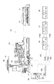
図1は、本発明の一実施の形態に係る鍵盤楽器である鍵盤装置の構成を、ある1つの鍵に着目して示した部分断面図である。本鍵盤装置30は、自動演奏ピアノとして構成される。鍵盤装置30は、通常のアコーステックピアノと同様、鍵31の運動をハンマ32に伝達するアクションメカニズム33と、ハンマ32により打撃される弦34と、弦34の振動を止めるためのダンパ36とを備えている。以降、鍵31の奏者側を「前方」と称する。
FIG. 1 is a partial cross-sectional view showing a configuration of a keyboard device that is a keyboard instrument according to an embodiment of the present invention, paying attention to a certain key. The
また、不図示のソレノイドコイルを有するキードライブユニット20が、鍵31ごとに設けられ、鍵31の後端部側の下方に配置されている。また、キーセンサユニット37が各鍵31に対応して設けられる。キーセンサユニット37は、各鍵31の前部下方に配置され、鍵31が押下された状態になると、その鍵31の押下位置を示す信号を出力する。
A
演奏データ中の発音イベントデータで規定される音高に対応するキードライブユニット20に駆動信号が供給されると、そのプランジャが上昇して対応する鍵31の後端部を突き上げる。これにより鍵31が押下され、弦34がハンマ32により叩かれることによりピアノ音が発音されるようになっている。
When a drive signal is supplied to the
鍵盤装置30にはまた、ダンパ36を駆動するためのラウドペダルであるペダルPDが設けられる。また、ペダルPDを駆動するためのペダルアクチュエータ26と、ペダルPDの位置を検出する位置センサ27とが設けられている。詳細は図示しないが、ペダルアクチュエータ26は公知の構成のもので、ペダルPDに連結されたプランジャ29と、該プランジャ29に巻装されたソレノイドコイル28とを有し(いずれも図2参照)、駆動信号が供給されると、上記プランジャ29が動作してペダルPDが駆動されるようになっている。
The
鍵盤装置30はまた、ピアノコントローラ40、モーションコントローラ41及びサーボコントローラ42を備える。ピアノコントローラ40は、モーションコントローラ41に演奏データを供給する。この演奏データは、例えば、MIDI(Musical Instrument Digital Interface)コードで構成され、鍵31及びペダルPDの動作を規定する。モーションコントローラ41は、供給された演奏データに基づいて、各時刻におけるペダルPD及び鍵31の各位置に対応した位置制御データPr(p)、Pr(k)をそれぞれ生成し、サーボコントローラ42に供給する。一方、位置センサ27の検出信号が、フィードバック信号Py(p)としてサーボコントローラ42に供給され、また、キードライブユニット20のソレノイドコイルからも、同様にフィードバック信号Py(k)がサーボコントローラ42に供給される。
The
サーボコントローラ42は、位置制御データPr(p)、Pr(k)に応じた励磁電流として電流指示値u(p)、u(k)を生成し、それぞれペダルアクチュエータ26、キードライブユニット20に供給する。これら電流指示値u(p)、u(k)は、実際には、ペダルアクチュエータ26、キードライブユニット20のそれぞれのソレノイドコイルに流すべき平均電流の目標値に応じたデューティ比となるようにパルス幅変調を施したPWM信号である。
The
演奏データに基づく自動演奏においては、サーボコントローラ42は、位置制御データPr(p)、Pr(k)とフィードバック信号Py(p)、Py(k)とをそれぞれ比較し、両者がそれぞれ一致するように電流指示値u(p)、u(k)を随時更新して出力することでサーボ制御を行う。これにより、演奏データに従って、ペダルPD及び鍵31が駆動されて、自動演奏がなされる。
In the automatic performance based on the performance data, the
図2は、鍵盤装置30の制御機構の構成を示すブロック図である。
FIG. 2 is a block diagram showing the configuration of the control mechanism of the
鍵盤装置30の制御機構は、CPU11に、バス15を通じて、上記キードライブユニット20、ペダルアクチュエータ26、位置センサ27、キーセンサユニット37のほか、鍵盤部KB、ROM12、RAM13、MIDIインターフェイス(MIDII/F)14、タイマ16、表示部17、外部記憶装置18、操作部19、音源回路21、効果回路22及び記憶部25が接続されて構成される。音源回路21には効果回路22を介してサウンドシステム23が接続されている。
In addition to the
CPU11は、本装置30全体の制御を司る。ROM12は、CPU11が実行する制御プログラムやテーブルデータ等の各種データを記憶する。RAM13は、演奏データ、テキストデータ等の各種入力情報、各種フラグやバッファデータ及び演算結果等を一時的に記憶する。MIDII/F14は、不図示のMIDI機器等からの演奏データをMIDI信号として入力する。タイマ16は、タイマ割り込み処理における割り込み時間や各種時間を計時する。表示部17は、例えばLCDを含んで構成され、楽譜等の各種情報を表示する。外部記憶装置18は、フレキシブルディスク等の不図示の可搬記憶媒体に対してアクセス可能に構成され、これら可搬記憶媒体に対して演奏データ等のデータを読み書きすることができる。操作部19は、不図示の各種操作子を有し、自動演奏のスタート/ストップの指示、曲選択等の指示、各種設定等を行う。記憶部25は、フラッシュメモリ等の不揮発メモリで構成され、演奏データ等の各種データを記憶することができる。鍵盤部KBには、上記鍵31が含まれる。
The
音源回路21は、演奏データを楽音信号に変換する。効果回路22は、音源回路21から入力される楽音信号に各種効果を付与し、DAC(Digital-to-Analog Converter)やアンプ、スピーカ等のサウンドシステム23が、効果回路22から入力される楽音信号等を音響に変換する。
The
なお、上記モーションコントローラ41及びサーボコントローラ42の機能は、実際には、CPU11、タイマ16、ROM12、RAM13等の協働作用によって実現される。
Note that the functions of the
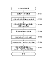
図3は、本実施の形態におけるペダル制御処理の手順を示すフローチャートである。本処理は一定間隔で(例えば4msec毎に)実行される。 FIG. 3 is a flowchart showing a procedure of pedal control processing in the present embodiment. This process is executed at regular intervals (for example, every 4 msec).
まず、モーションコントローラ41がピアノコントローラ40から演奏データを取得し(ステップS101)、その演奏データに基づいて、ペダルPDの深さ目標値である位置制御データPr(p)を生成する(ステップS102)。この位置制御データPr(p)はサーボコントローラ42に供給される。なお、このとき、サーボコントローラ42が、供給される位置制御データPr(p)に所定の補間処理を施すようにしてもよい。
First, the
次に、サーボコントローラ42は、ペダルPDの位置情報であるフィードバック信号Py(p)を取得すると共に、該フィードバック信号Py(p)からペダルPDの速度v(p)を算出する(ステップS103)。そして、サーボコントローラ42は、上記供給された位置制御データPr(p)、取得したフィードバック信号Py(p)及び算出した速度v(p)に基づいて、ペダルアクチュエータ26のソレノイドコイル28に次に供給すべき目標電流値ru1を演算する(ステップS104)。
Next, the
図4は、ペダルアクチュエータ26に供給される目標電流値及びペダルアクチュエータ26のソレノイドコイル28の電流値の立ち上がりの遷移を示すタイムチャートである。
FIG. 4 is a time chart showing the transition of the rising of the target current value supplied to the
仮に、現在時刻t0において、サーボコントローラ42から、ソレノイドコイル28に電流指示値u(p)として目標電流値ru0が供給されているときに、ペダルPDの深さ目標値が変化し、新たな目標電流値ru1が生成されたとする。ここで、従来の手法であれば、深さ目標値が更新されるまでの間、例えば、時刻t0から時刻t2までの間(約4msec)、電流指示値u(p)として、現在の目標電流値ru0に代わって次の目標電流値ru1がそのまま供給されることになる。ソレノイドコイル28の電流値は、理想的には目標電流値ru1にほぼ従って直ちに立ち上がるのが好ましい。しかし、ソレノイドコイル28は時定数τの一時遅れ要素を有するため、その実際の電流値は第1曲線cAで示されるように遅延して立ち上がる。そこで、本実施の形態では、以下に説明するように、目標電流値ru1を補正した補正目標電流値ru(temp)を一時的に供給するようにする。
If the target current value ru0 is supplied as the current instruction value u (p) from the
図3に戻り、続くステップS105では、サーボコントローラ42は、補正目標電流値ru(temp)を、現在供給している電流指示値u(p)(時刻t0においては目標電流値ru0)と新たに生成した目標電流値ru1とに基づいて、下記数式1により算出する。
Returning to FIG. 3, in the subsequent step S105, the
(数1)
ru(temp)=ru1+(ru1−u(p))
次に、上記算出した補正目標電流値ru(temp)をペダルアクチュエータ26のソレノイドコイル28に供給し(ステップS106)、これを所定時間T(例えば1.5msec)に亘って(例えば、時刻t0から時刻t1まで)継続する(図4参照)。そして、所定時間T経過後に、上記生成した目標電流値ru1を供給する、すなわち、供給する電流指示値u(p)を補正目標電流値ru(temp)から目標電流値ru1に戻して(ステップS107)、本処理を終了する。
(Equation 1)
ru (temp) = ru1 + (ru1-u (p))
Next, the calculated corrected target current value ru (temp) is supplied to the
その結果、図4の例では、ソレノイドコイル28の電流値は、第2曲線cBで示されるように、時刻t0から時刻t1にかけては、補正目標電流値ru(temp)に向かって遷移するので、従来の制御手法の場合のように目標電流値ru1に向かって遷移するのに比し、速やかに立ち上がる。また、ソレノイドコイル28の電流値は、時刻t1から時刻t2にかけては、目標電流値ru1に向かって緩やかに遷移するが、時刻t1で既に目標電流値ru1に近い値になっているため、結果として、第1曲線cAに比し目標電流値ru1との差異が常に小さく遷移する。
As a result, in the example of FIG. 4, the current value of the
図4では、現在供給している電流指示値u(p)よりも新たな目標電流値ru1が高いという例を示したが、電流指示値u(p)よりも新たな目標電流値ru1が低い場合にも同様に処理でき、例えばステップS105では、上記数式1により補正目標電流値ru(temp)を算出すればよい。 FIG. 4 shows an example in which the new target current value ru1 is higher than the current instruction value u (p) currently supplied, but the new target current value ru1 is lower than the current instruction value u (p). In this case, the same processing can be performed. For example, in step S105, the corrected target current value ru (temp) may be calculated by the above equation 1.
本実施の形態によれば、新たに生成された目標電流値ru1をソレノイドコイル28に供給するにあたって、現在供給している電流指示値u(p)に対する目標電流値ru1の変化方向に目標電流値ru1を補正した補正目標電流値ru(temp)を所定時間Tに亘って供給した後に、目標電流値ru1を供給するようにしたので、ペダルPDを、演奏データに従った目標位置に速やかに制御することができる。
According to the present embodiment, when the newly generated target current value ru1 is supplied to the
また、上記数式1のような設定により、ソレノイドコイル28の電流値を安定的に目標電流値ru1に収束させ、ペダルPDにおいて、チャタリング(ペダルノイズ)等の不安定な動作の発生を回避することができる。
Further, the current value of the
すなわち、上記数式1によると、現在の電流指示値u(p)が仮に0であるとすると、目標電流値ru1の2倍の値が補正目標電流値ru(temp)となることから、最高で目標電流値ru1の2倍の値が一時的に供給され得ることになる。また、所定時間Tは、目標電流値ru1の更新間隔(図3のペダル制御処理の実行間隔である4msec)の1.5/4倍という設定である。仮に、補正目標電流値ru(temp)を、目標電流値ru1の3倍、4倍といった大きすぎる値に設定し、あるいは所定時間Tをもっと長くして目標電流値ru1の更新間隔に近い値に設定したとすると、制御が発振し、第2曲線cBが目標電流値ru1を大きくオーバーシュートするおそれがある。少々のオーバーシュートは問題ないが、大きすぎると収束性が悪く制御が不安定となる。従って、上記数式1は一例であるが、目標電流値ru1の補正の度合いと、補正目標電流値ru(temp)を供給する所定時間Tとは、製品仕様に応じて個々に最適値となるように設定し、それに応じて補正のための式も設定するのが好ましい。 That is, according to the above equation 1, if the current current instruction value u (p) is assumed to be 0, a value twice as large as the target current value ru1 becomes the corrected target current value ru (temp). A value twice as large as the target current value ru1 can be temporarily supplied. The predetermined time T is set to 1.5 / 4 times the update interval of the target current value ru1 (4 msec, which is the execution interval of the pedal control process in FIG. 3). Temporarily, the correction target current value ru (temp) is set to a value that is too large, such as three times or four times the target current value ru1, or the predetermined time T is further increased to a value close to the update interval of the target current value ru1. If set, the control oscillates and the second curve cB may overshoot the target current value ru1 greatly. A slight overshoot is not a problem, but if it is too large, the convergence is poor and the control becomes unstable. Therefore, although the above equation 1 is an example, the degree of correction of the target current value ru1 and the predetermined time T for supplying the corrected target current value ru (temp) are individually optimum values according to the product specifications. It is preferable to set an equation for correction accordingly.
具体的には、例えば、第2曲線cBが目標電流値ru1に達すると想定される時刻tx(不図示)を求め、現在時刻t0から時刻txまでの時間Txより短い範囲で(例えば、時間Txの0.8倍等に)所定時間Tを定めてもよい。その場合、さらに、サーボコントローラ42におけるサンプリング間隔の整数倍とするのが望ましい。一方、目標電流値ru1の補正の度合いを決定する上で、補正目標電流値ru(temp)は、常に、デューティ比の変更限度の値としてもよい。すなわち、増大方向なら100(%)、減少方向なら0(%)である。その場合においても、所定時間Tは、上記のような手法で定めてもよい。あるいは、所定時間Tを先に定め、ソレノイドコイル28の電流値が所定時間T経過後に目標電流値ru1に達するような曲線(第2曲線cBよりもさらに立ち上がりが急な曲線)の漸近値を、補正目標電流値ru(temp)として設定してもよい。
Specifically, for example, a time tx (not shown) that is assumed that the second curve cB reaches the target current value ru1 is obtained, and within a range shorter than the time Tx from the current time t0 to the time tx (for example, the time Tx The predetermined time T may be determined (for example, 0.8 times the time). In that case, it is desirable that the sampling interval in the
なお、制御の収束性を高める観点からは、目標電流値ru1が現在の電流指示値u(p)に対して高い場合においては、現在の電流指示値u(p)が低いときほど上記補正の度合いを大きく、所定時間Tを長く設定するのが望ましく、逆に、目標電流値ru1が現在の電流指示値u(p)に対して低い場合においては、現在の電流指示値u(p)が高いときほど上記補正の度合いを大きく、所定時間Tを長く設定するのが望ましい。 From the viewpoint of improving the convergence of the control, when the target current value ru1 is higher than the current current instruction value u (p), the lower the current current instruction value u (p), the more the correction is performed. It is desirable to set the degree large and set the predetermined time T long. Conversely, when the target current value ru1 is lower than the current current instruction value u (p), the current current instruction value u (p) is It is desirable to increase the degree of correction and set the predetermined time T longer as the value is higher.
ところで、電流指示値u(p)は、実際には、上述のように、流すべき平均電流の目標値に応じたデューティ比のPWM信号であって、デューティ比の変更限度は100(%)であるから、新たな目標電流値ru1が現在の電流指示値u(p)に対して高い場合において、現在の電流指示値u(p)と所定の関係を持つ(例えば「ru1−u(p)」が、ディーティ比50%以上である)ときは、上記数式1による補正目標電流値ru(temp)の供給が不可能な場合があり得る。そのような場合は、図3のステップS106において、デューティ比の変更限度(100%または0%)を供給する。 By the way, the current instruction value u (p) is actually a PWM signal having a duty ratio corresponding to the target value of the average current to be passed as described above, and the duty ratio change limit is 100 (%). Therefore, when the new target current value ru1 is higher than the current current instruction value u (p), it has a predetermined relationship with the current current instruction value u (p) (for example, “ru1-u (p) ”Is a duty ratio of 50% or more), it may be impossible to supply the corrected target current value ru (temp) according to Equation 1 above. In such a case, a duty ratio change limit (100% or 0%) is supplied in step S106 of FIG.
かかる観点からは、目標電流値ru1が、現在の電流指示値u(p)より非常に高い(例えばディーティ比50%以上)場合、及び現在の電流指示値u(p)より非常に低い場合は、収束性を高めるという効果があまり発揮されないとも考えられる。しかし、このような場合は、目標電流値ru1の電流指示値u(p)に対する変化量が小さくとも元々電流指示値u(p)が限度値に近い値である場合、若しくは上記変化量が元々大きい場合である。前者の場合は電流値の速やかな立ち上がりの要求が低く、後者の場合も限度値寄りの目標電流を与えることに変わりはない。従って、目標電流値ru1が電流指示値u(p)に対して大きく変化したときほどソレノイドコイル28の電流値の速やかな立ち上がりが要求されることに鑑みれば、本発明は実際上きわめて有用である。
From this point of view, when the target current value ru1 is much higher than the current current instruction value u (p) (eg, the duty ratio is 50% or more) and when it is much lower than the current current instruction value u (p). It is thought that the effect of improving the convergence is not so much exhibited. However, in such a case, even if the change amount of the target current value ru1 with respect to the current instruction value u (p) is small, the current instruction value u (p) is originally close to the limit value, or the change amount is originally It is a big case. In the former case, the demand for quick rise of the current value is low, and in the latter case, a target current close to the limit value is still given. Therefore, in view of the fact that the quicker rise of the current value of the
なお、図3のペダル制御処理は、一定の間隔(4msec)で実行されるとしたが、例えば、前記ステップS101、S102に相当する処理をモーションコントローラ41において20msec間隔で実行すると共に、これと並行して、前記ステップS103〜S107に相当する処理をサーボコントローラ42において4msec間隔で実行するようにしてもよい。あるいは、サーボコントローラ42とペダルアクチュエータ26との間にマイクロコンピュータを設け、前記ステップS106、S107に相当する処理をマイクロコンピュータに実行させるようにしてもよい。
3 is executed at regular intervals (4 msec), for example, the processing corresponding to steps S101 and S102 is executed at intervals of 20 msec in the
なお、本実施の形態では、制御対象としてラウドペダルを例示したが、これに限られず、例えば、シフトペダル等の他のペダルや、鍵31等、各種操作子に同様に本発明を適用することができる。 In the present embodiment, the loud pedal is exemplified as the control target. However, the present invention is not limited thereto, and the present invention can be similarly applied to other pedals such as a shift pedal, the key 31, and the like. it can.
26 ペダルアクチュエータ、 28 ソレノイドコイル、 30 鍵盤装置(鍵盤楽器)、 41 モーションコントローラ、 42 サーボコントローラ(目標位置情報取得手段、目標電流値生成手段、駆動制御手段)、 PD ペダル(操作子)、 Pr(p) 位置制御データ(目標位置情報)、 ru1 目標電流値、 u(p) 電流指示値(現在電流値)、 ru(temp) 補正目標電流値、 T 所定時間 26 Pedal actuator, 28 Solenoid coil, 30 Keyboard device (Keyboard instrument), 41 Motion controller, 42 Servo controller (Target position information acquisition means, Target current value generation means, Drive control means), PD pedal (Operator), Pr ( p) position control data (target position information), ru1 target current value, u (p) current indication value (current current value), ru (temp) corrected target current value, T predetermined time
Claims (1)
前記操作子の目標位置を規定する目標位置情報を順次取得する目標位置情報取得手段と、
前記目標位置情報取得手段により取得された目標位置情報に基づき前記ソレノイドコイルに供給すべき目標電流値を順次生成する目標電流値生成手段と、
前記目標電流値生成手段により生成された目標電流値を前記ソレノイドコイルに順次供給して該ソレノイドコイルを駆動制御する駆動制御手段とを有し、
前記駆動制御手段は、前記生成された目標電流値を前記ソレノイドコイルに供給する際、前記ソレノイドコイルに現在供給している目標電流値を前記生成された目標電流値から差し引いた値を前記生成された目標電流値に加算することで補正目標電流値を算出すると共に、該算出した補正目標電流値を、前記現在供給している目標電流値に代えて所定時間に亘って供給し、その後、前記生成された目標電流値を供給することを特徴とする鍵盤楽器。 A keyboard instrument having an operator driven by supplying current to a solenoid coil,
Target position information acquisition means for sequentially acquiring target position information defining the target position of the operator;
Target current value generating means for sequentially generating target current values to be supplied to the solenoid coil based on the target position information acquired by the target position information acquiring means;
Drive control means for driving the solenoid coil by sequentially supplying the target current value generated by the target current value generating means to the solenoid coil;
When the drive control means supplies the generated target current value to the solenoid coil, the drive control means generates a value obtained by subtracting the target current value currently supplied to the solenoid coil from the generated target current value. In addition to calculating the corrected target current value by adding to the target current value, the calculated corrected target current value is supplied over a predetermined time instead of the currently supplied target current value. A keyboard instrument characterized by supplying a generated target current value.
Priority Applications (3)
| Application Number | Priority Date | Filing Date | Title |
|---|---|---|---|
| JP2004060623A JP4218552B2 (en) | 2004-03-04 | 2004-03-04 | Keyboard instrument |
| US11/054,412 US7238873B2 (en) | 2004-03-04 | 2005-02-09 | Automatic player musical instrument exactly reproducing performance and automatic player used therein |
| CN200510053018.9A CN1664916B (en) | 2004-03-04 | 2005-03-04 | Automatic player musical instrument exactly reproducing performance and automatic player used therein |
Applications Claiming Priority (1)
| Application Number | Priority Date | Filing Date | Title |
|---|---|---|---|
| JP2004060623A JP4218552B2 (en) | 2004-03-04 | 2004-03-04 | Keyboard instrument |
Publications (2)
| Publication Number | Publication Date |
|---|---|
| JP2005250120A JP2005250120A (en) | 2005-09-15 |
| JP4218552B2 true JP4218552B2 (en) | 2009-02-04 |
Family
ID=34988222
Family Applications (1)
| Application Number | Title | Priority Date | Filing Date |
|---|---|---|---|
| JP2004060623A Expired - Fee Related JP4218552B2 (en) | 2004-03-04 | 2004-03-04 | Keyboard instrument |
Country Status (3)
| Country | Link |
|---|---|
| US (1) | US7238873B2 (en) |
| JP (1) | JP4218552B2 (en) |
| CN (1) | CN1664916B (en) |
Families Citing this family (13)
| Publication number | Priority date | Publication date | Assignee | Title |
|---|---|---|---|---|
| EP1575026A2 (en) * | 2004-03-12 | 2005-09-14 | Yamaha Corporation | Automatic player musical instrument, for exactly controlling the keys |
| JP4192828B2 (en) * | 2004-04-21 | 2008-12-10 | ヤマハ株式会社 | Automatic performance device |
| JP4193752B2 (en) * | 2004-05-07 | 2008-12-10 | ヤマハ株式会社 | Automatic piano |
| JP4687474B2 (en) * | 2006-01-26 | 2011-05-25 | ヤマハ株式会社 | Keyboard instrument |
| US8686275B1 (en) * | 2008-01-15 | 2014-04-01 | Wayne Lee Stahnke | Pedal actuator with nonlinear sensor |
| JP5509574B2 (en) * | 2008-10-29 | 2014-06-04 | ヤマハ株式会社 | Solenoid control device and automatic performance device |
| JP2010160424A (en) * | 2009-01-09 | 2010-07-22 | Yamaha Corp | Pedal output conversion device and program |
| JP5338401B2 (en) * | 2009-03-13 | 2013-11-13 | ヤマハ株式会社 | Key drive device, upright automatic piano and program |
| JP5736917B2 (en) * | 2011-04-05 | 2015-06-17 | ヤマハ株式会社 | Keyboard instrument, program, performance data conversion program and device |
| EP2618327B1 (en) | 2012-01-18 | 2016-03-30 | Yamaha Corporation | Damper drive device for musical instrument, and musical instrument |
| JP6648414B2 (en) * | 2015-05-20 | 2020-02-14 | ヤマハ株式会社 | Keyboard instruments and keyboard instrument automatic performance programs |
| CN105390128B (en) * | 2015-11-09 | 2019-10-11 | 清华大学 | Automatic playing mechanism and percussion instrument automatic playing system |
| CN111243559B (en) * | 2020-01-09 | 2024-12-13 | 杨缤纷 | Combined musical instrument and electronic music processing method |
Family Cites Families (39)
| Publication number | Priority date | Publication date | Assignee | Title |
|---|---|---|---|---|
| CA1280918C (en) * | 1988-01-29 | 1991-03-05 | Yasutoshi Kaneko | Automatic player piano with touch strength estimator |
| JP2606616B2 (en) | 1989-01-19 | 1997-05-07 | ヤマハ株式会社 | Automatic piano |
| US5131306A (en) * | 1989-01-19 | 1992-07-21 | Yamaha Corporation | Automatic music playing piano |
| US5022301A (en) * | 1989-09-08 | 1991-06-11 | Stahnke Wayne L | Multiplexed multiple intensity reproducing piano |
| US5262586A (en) * | 1991-02-21 | 1993-11-16 | Yamaha Corporation | Sound controller incorporated in acoustic musical instrument for controlling qualities of sound |
| US5451706A (en) * | 1992-02-14 | 1995-09-19 | Yamaha Corporation | Automatic player piano equipped with mute lock system for reproducing faint sounds in playback mode |
| US5568138A (en) * | 1993-01-14 | 1996-10-22 | Yamaha Corporation | Servo-controlling system incorporated in keyboard instrument for processing parallel input signals in time sharing fashion |
| JP2737669B2 (en) * | 1993-12-10 | 1998-04-08 | ヤマハ株式会社 | Keyboard drive for automatic performance piano |
| US5652399A (en) * | 1993-12-17 | 1997-07-29 | Yamaha Corporation | Automatic player piano and estimator for acceleration of depressed key incorporated in the automatic player piano |
| JP3620063B2 (en) * | 1994-03-25 | 2005-02-16 | ヤマハ株式会社 | Automatic piano and performance data processing device |
| JP3586882B2 (en) * | 1994-03-28 | 2004-11-10 | ヤマハ株式会社 | Automatic performance system for keyboard instruments |
| JP3603375B2 (en) * | 1995-04-14 | 2004-12-22 | ヤマハ株式会社 | Keyboard instrument |
| JP3588872B2 (en) * | 1995-09-19 | 2004-11-17 | ヤマハ株式会社 | Automatic piano |
| JPH10161648A (en) * | 1996-12-04 | 1998-06-19 | Yamaha Corp | Keying-string hammering characteristic conforming device, drive signal-string hammering characteristic conforming device, and keyed instrument |
| JP3807030B2 (en) * | 1997-01-14 | 2006-08-09 | ヤマハ株式会社 | Keyboard musical instrument, electronic musical instrument and method, and recording medium |
| JP3890649B2 (en) * | 1997-02-21 | 2007-03-07 | ヤマハ株式会社 | Automatic piano performance data converter |
| JP3887968B2 (en) * | 1998-09-18 | 2007-02-28 | ヤマハ株式会社 | Keyboard instrument and key speed judgment device |
| US6271447B1 (en) * | 1998-10-05 | 2001-08-07 | Yamaha Corporation | Velocity calculating system for moving object widely varied in velocity method for correcting velocity and keyboard musical instrument equipped with the velocity calculating system for accurately determining loudness of sounds |
| CN2362174Y (en) * | 1999-03-30 | 2000-02-02 | 贾宝丁 | Automatic player |
| JP2001035719A (en) * | 1999-07-22 | 2001-02-09 | Yamaha Corp | Connection structure for solenoid, solenoid device, and automatic playing device for keyboard instrument |
| JP4069557B2 (en) * | 1999-12-16 | 2008-04-02 | ヤマハ株式会社 | Hammer detection device and performance information acquisition device |
| JP4608718B2 (en) * | 2000-01-12 | 2011-01-12 | ヤマハ株式会社 | Musical instrument |
| JP2002007014A (en) * | 2000-06-19 | 2002-01-11 | Yamaha Corp | Information processor and musical instrument provided with the information processor |
| JP4595193B2 (en) * | 2000-11-17 | 2010-12-08 | ヤマハ株式会社 | Hammer detection device |
| US7897865B2 (en) * | 2002-01-15 | 2011-03-01 | Yamaha Corporation | Multimedia platform for recording and/or reproducing music synchronously with visual images |
| JP3891410B2 (en) * | 2002-03-05 | 2007-03-14 | ヤマハ株式会社 | Performance equipment |
| JP2004294772A (en) * | 2003-03-27 | 2004-10-21 | Yamaha Corp | Automatic playing piano |
| JP4075771B2 (en) * | 2003-11-04 | 2008-04-16 | ヤマハ株式会社 | Estimation device, automatic musical instrument and program |
| US6992241B2 (en) * | 2003-12-25 | 2006-01-31 | Yamaha Corporation | Automatic player musical instrument for exactly reproducing performance and automatic player incorporated therein |
| JP4222210B2 (en) * | 2004-01-06 | 2009-02-12 | ヤマハ株式会社 | Performance system |
| JP4129798B2 (en) * | 2004-01-06 | 2008-08-06 | ヤマハ株式会社 | Optical detector |
| JP4489442B2 (en) * | 2004-01-13 | 2010-06-23 | ヤマハ株式会社 | Keyboard device |
| EP1575026A2 (en) * | 2004-03-12 | 2005-09-14 | Yamaha Corporation | Automatic player musical instrument, for exactly controlling the keys |
| JP4179226B2 (en) * | 2004-03-26 | 2008-11-12 | セイコーエプソン株式会社 | Droplet ejection apparatus and ejection abnormality detection method for droplet ejection head |
| JP4192828B2 (en) * | 2004-04-21 | 2008-12-10 | ヤマハ株式会社 | Automatic performance device |
| US7453037B2 (en) * | 2004-04-22 | 2008-11-18 | Yamaha Corporation | Musical performance apparatus |
| JP4193752B2 (en) * | 2004-05-07 | 2008-12-10 | ヤマハ株式会社 | Automatic piano |
| JP4214966B2 (en) * | 2004-08-06 | 2009-01-28 | ヤマハ株式会社 | Musical instrument self-diagnosis program |
| JP4375200B2 (en) * | 2004-11-01 | 2009-12-02 | ヤマハ株式会社 | Basic information output device for haptic control |
-
2004
- 2004-03-04 JP JP2004060623A patent/JP4218552B2/en not_active Expired - Fee Related
-
2005
- 2005-02-09 US US11/054,412 patent/US7238873B2/en not_active Expired - Lifetime
- 2005-03-04 CN CN200510053018.9A patent/CN1664916B/en not_active Expired - Fee Related
Also Published As
| Publication number | Publication date |
|---|---|
| CN1664916B (en) | 2010-06-16 |
| US7238873B2 (en) | 2007-07-03 |
| CN1664916A (en) | 2005-09-07 |
| JP2005250120A (en) | 2005-09-15 |
| US20050211049A1 (en) | 2005-09-29 |
Similar Documents
| Publication | Publication Date | Title |
|---|---|---|
| JP4218552B2 (en) | Keyboard instrument | |
| JP4524798B2 (en) | Method and apparatus for identifying half point of pedal of keyboard instrument, and program | |
| JP2927858B2 (en) | Automatic piano | |
| KR100659647B1 (en) | Automatic player musical instrument for exactly reproducing performance and automatic player incorporated therein | |
| JP4375200B2 (en) | Basic information output device for haptic control | |
| JP4193752B2 (en) | Automatic piano | |
| JP5028849B2 (en) | Method and apparatus for identifying half point of pedal of keyboard instrument | |
| JP5736917B2 (en) | Keyboard instrument, program, performance data conversion program and device | |
| US12027144B2 (en) | Keyboard device and sound generation control method | |
| JP2006267447A (en) | Keyboard instrument | |
| JP2014112221A (en) | Drive control device for percussion member in sound production mechanism | |
| JP2006084687A (en) | Playing drive device of musical instrument, method for driving playing operator of musical instrument under feedback control, and computer-executable control program for same method | |
| US9947306B2 (en) | Electric acoustic apparatus | |
| JP4345690B2 (en) | Keyboard instrument and operating element reaction force optimization system | |
| JP6064758B2 (en) | Keyboard instrument | |
| JP2014130197A (en) | Half point specification method, device, and program of pedal of keyboard musical instrument | |
| JP3997956B2 (en) | Performance equipment | |
| JP5104928B2 (en) | Performance information playback device | |
| JP2009198551A (en) | Musical instrument playing robot and automatic musical instrument playing method | |
| US11557270B2 (en) | Performance analysis method and performance analysis device | |
| US20100043619A1 (en) | System and method for driving actuators in a reproducing piano | |
| JP4673156B2 (en) | Automatic performance apparatus and control method thereof | |
| JP4677800B2 (en) | Performance information playback device | |
| JP4110691B2 (en) | Keyboard instrument sensor data conversion apparatus and sensor data conversion method | |
| JP2014206578A (en) | Keyboard instrument |
Legal Events
| Date | Code | Title | Description |
|---|---|---|---|
| RD03 | Notification of appointment of power of attorney |
Free format text: JAPANESE INTERMEDIATE CODE: A7423 Effective date: 20060424 |
|
| A621 | Written request for application examination |
Free format text: JAPANESE INTERMEDIATE CODE: A621 Effective date: 20060824 |
|
| A977 | Report on retrieval |
Free format text: JAPANESE INTERMEDIATE CODE: A971007 Effective date: 20080222 |
|
| A131 | Notification of reasons for refusal |
Free format text: JAPANESE INTERMEDIATE CODE: A131 Effective date: 20080228 |
|
| A521 | Request for written amendment filed |
Free format text: JAPANESE INTERMEDIATE CODE: A523 Effective date: 20080424 |
|
| A131 | Notification of reasons for refusal |
Free format text: JAPANESE INTERMEDIATE CODE: A131 Effective date: 20080729 |
|
| A521 | Request for written amendment filed |
Free format text: JAPANESE INTERMEDIATE CODE: A523 Effective date: 20080925 |
|
| TRDD | Decision of grant or rejection written | ||
| A01 | Written decision to grant a patent or to grant a registration (utility model) |
Free format text: JAPANESE INTERMEDIATE CODE: A01 Effective date: 20081021 |
|
| A01 | Written decision to grant a patent or to grant a registration (utility model) |
Free format text: JAPANESE INTERMEDIATE CODE: A01 |
|
| A61 | First payment of annual fees (during grant procedure) |
Free format text: JAPANESE INTERMEDIATE CODE: A61 Effective date: 20081103 |
|
| FPAY | Renewal fee payment (event date is renewal date of database) |
Free format text: PAYMENT UNTIL: 20111121 Year of fee payment: 3 |
|
| R150 | Certificate of patent or registration of utility model |
Ref document number: 4218552 Country of ref document: JP Free format text: JAPANESE INTERMEDIATE CODE: R150 Free format text: JAPANESE INTERMEDIATE CODE: R150 |
|
| FPAY | Renewal fee payment (event date is renewal date of database) |
Free format text: PAYMENT UNTIL: 20111121 Year of fee payment: 3 |
|
| FPAY | Renewal fee payment (event date is renewal date of database) |
Free format text: PAYMENT UNTIL: 20121121 Year of fee payment: 4 |
|
| FPAY | Renewal fee payment (event date is renewal date of database) |
Free format text: PAYMENT UNTIL: 20121121 Year of fee payment: 4 |
|
| FPAY | Renewal fee payment (event date is renewal date of database) |
Free format text: PAYMENT UNTIL: 20131121 Year of fee payment: 5 |
|
| LAPS | Cancellation because of no payment of annual fees |