JP3588872B2 - Automatic piano - Google Patents
Automatic piano Download PDFInfo
- Publication number
- JP3588872B2 JP3588872B2 JP24032495A JP24032495A JP3588872B2 JP 3588872 B2 JP3588872 B2 JP 3588872B2 JP 24032495 A JP24032495 A JP 24032495A JP 24032495 A JP24032495 A JP 24032495A JP 3588872 B2 JP3588872 B2 JP 3588872B2
- Authority
- JP
- Japan
- Prior art keywords
- key
- trajectory
- release
- time
- slow
- Prior art date
- Legal status (The legal status is an assumption and is not a legal conclusion. Google has not performed a legal analysis and makes no representation as to the accuracy of the status listed.)
- Expired - Fee Related
Links
- 230000000994 depressogenic effect Effects 0.000 claims description 17
- 238000004364 calculation method Methods 0.000 claims description 11
- 230000000881 depressing effect Effects 0.000 claims description 7
- 238000000034 method Methods 0.000 description 36
- 230000014509 gene expression Effects 0.000 description 27
- 238000010586 diagram Methods 0.000 description 20
- 230000008569 process Effects 0.000 description 20
- 230000033001 locomotion Effects 0.000 description 16
- 230000001133 acceleration Effects 0.000 description 12
- 238000007781 pre-processing Methods 0.000 description 9
- 230000008859 change Effects 0.000 description 8
- 238000002474 experimental method Methods 0.000 description 4
- 230000033764 rhythmic process Effects 0.000 description 4
- 238000010079 rubber tapping Methods 0.000 description 4
- 230000009471 action Effects 0.000 description 3
- 230000006399 behavior Effects 0.000 description 2
- 230000006870 function Effects 0.000 description 2
- 230000001788 irregular Effects 0.000 description 2
- 238000012887 quadratic function Methods 0.000 description 2
- 230000007704 transition Effects 0.000 description 2
- 238000004891 communication Methods 0.000 description 1
- 230000003111 delayed effect Effects 0.000 description 1
- 230000000694 effects Effects 0.000 description 1
- 238000005516 engineering process Methods 0.000 description 1
- 238000012886 linear function Methods 0.000 description 1
- 238000010606 normalization Methods 0.000 description 1
Images


Classifications
-
- G—PHYSICS
- G10—MUSICAL INSTRUMENTS; ACOUSTICS
- G10F—AUTOMATIC MUSICAL INSTRUMENTS
- G10F1/00—Automatic musical instruments
- G10F1/02—Pianofortes with keyboard
-
- G—PHYSICS
- G10—MUSICAL INSTRUMENTS; ACOUSTICS
- G10C—PIANOS, HARPSICHORDS, SPINETS OR SIMILAR STRINGED MUSICAL INSTRUMENTS WITH ONE OR MORE KEYBOARDS
- G10C1/00—General design of pianos, harpsichords, spinets or similar stringed musical instruments with one or more keyboards
- G10C1/02—General design of pianos, harpsichords, spinets or similar stringed musical instruments with one or more keyboards of upright pianos
-
- G—PHYSICS
- G10—MUSICAL INSTRUMENTS; ACOUSTICS
- G10C—PIANOS, HARPSICHORDS, SPINETS OR SIMILAR STRINGED MUSICAL INSTRUMENTS WITH ONE OR MORE KEYBOARDS
- G10C3/00—Details or accessories
- G10C3/12—Keyboards; Keys
-
- G—PHYSICS
- G10—MUSICAL INSTRUMENTS; ACOUSTICS
- G10C—PIANOS, HARPSICHORDS, SPINETS OR SIMILAR STRINGED MUSICAL INSTRUMENTS WITH ONE OR MORE KEYBOARDS
- G10C3/00—Details or accessories
- G10C3/16—Actions
- G10C3/161—Actions specially adapted for upright pianos
Landscapes
- Physics & Mathematics (AREA)
- Engineering & Computer Science (AREA)
- Acoustics & Sound (AREA)
- Multimedia (AREA)
- Electrophonic Musical Instruments (AREA)
Description
【0001】
【発明が属する技術分野】
この発明は、自動的に鍵盤を駆動して演奏を行う自動ピアノに関する。
【0002】
【従来の技術】
自動ピアノにおいては、ソレノイドを励磁して鍵を駆動すると、これに応じてハンマが回転して打弦がおこなわれる。そして、ハンマによる打弦の強弱は、鍵の駆動速度に対応し、鍵の駆動速度はソレノイドへの供給電流に対応する。したがって、ソレノイドへの給電量を制御することにより、打弦の強弱、すなわち、発生楽音の大きさを制御することができる。
【0003】
また、自動ピアノにおいては、演奏情報を記録する際に、打弦直前のハンマの速度を検出し、これを打弦強度を示すデータ(以下、打弦強度データという)として記録するとともに、ハンマが打弦位置を通過する時刻を打弦時刻データとして記録する。なお、打弦時刻データは、一般的に一つ前の音との間隔を示す時間データ(相対時間データ)として記録されるが、演奏開始時からの絶対時刻が記録されることもある。
そして、記録した演奏情報を再生する際には、演奏情報中の打弦強度データに応じた電流をソレノイドに供給する。また、ソレノイドへの給電量制御は、一般にはパルス幅変調(PWM)によって行われる。
【0004】
この場合、鍵を駆動し始めてからハンマが実際に打弦するまでの時間差を見込んで、打弦時刻データが示す打弦タイミングより少し前にソレノイドへの給電を行う。また、強音と弱音では、押鍵開始から打弦までの時間が異なるので、打弦強度データに応じて、ソレノイドへの給電タイミングを調整するようにした自動ピアノも開発されている。
また、離鍵の場合は、鍵の離鍵タイミングをフォトセンサによって検出して記録し、再生時には離鍵タイミングに応じた時刻にソレノイドを非励磁にするという制御を行っていた。
【0005】
ところで、ピアノの演奏においては、いわゆるハーフストロークと言われる奏法がなされることがあり、この場合には、完全に押鍵される(鍵をエンド位置まで押し切る)前に離鍵が開始されたり、あるいは、離鍵の途中から次の押鍵操作に入る。
【0006】
しかしながら、従来の自動ピアノにおいては、押鍵タイミングの少し前にソレノイドを励磁し、離鍵タイミングの少し前にソレノイドを非励磁にするという単純な制御を行っており、押鍵や離鍵が途中までしか行われないハーフストロークの再現については、何等考慮されていなかった。このため、ハーフストロークで演奏される部分については、押鍵や離鍵にタイミングずれが生じ、特に、ハーフストロークの連打においては、再現が不能になるという問題が生じた。
【0007】
そこで、本出願人は、先に、押離鍵の開始時刻、完了時刻あるいは押離鍵の軌道の交差からハーフストロークか否かを判定し、ハーフストロークと判定した場合は、押鍵の途中から離鍵処理へ移行し、または離鍵の途中から押鍵処理に移行することにより、ハーフストロークを忠実に再現することができる自動ピアノを提案した(特願平5ー344242号)。
【0008】
【発明が解決しようとする課題】
ところが、上記自動ピアノにおいては、ハーフストロークで演奏する場合に押鍵の途中から離鍵処理へ移行し、または離鍵の途中から押鍵処理に移行するため、鍵の動作速度が急激に変化する。このため、特に、連打を行った場合に以下のような挙動を示す心配があった。
▲1▼離鍵から押鍵に移行するときに、鍵が跳ね返されるような状態となることがある。このような場合には、鍵に勢いが生じて音量が打弦強度データが示す値よりも大きくなる。
▲2▼離鍵から押鍵に移行するときに、鍵に生じた慣性のために押鍵が適切になされないことがあり、このような場合には、一部の打弦に抜けが生じたり、打弦のタイミングがずれてリズムが乱れたりする。
▲3▼エンド位置近くで連打を行うことにより、ダンパによる止音を弱くして発音の響きを大きくする演奏手法が用いられることがある。ところが、上記した技術では、離鍵の際に鍵が戻りすぎて止音が意図したよりも強くなる傾向がある。
▲4▼鍵の動作がシャープなため見た目が不自然となる。
以上は、連打による演奏を行った場合に予想される現象であるが、レスト位置からエンド位置の間で押離鍵を行うフルストロークの演奏を行った場合においても、鍵の動作開始が急激に行われるためその動作にゆらぎが生じることがあり、このような場合には打鍵や止音に乱れが生じる。
この発明は、上述した事情に鑑みてなされたもので、ハーフストロークによる演奏を行った場合に鍵に自然な動作を与えることができ、しかも、連打を円滑に行うことができる自動ピアノを提供することを目的としている。また、本発明は、フルストロークによる演奏を行った場合の鍵の動作のゆらぎを抑制することができる自動ピアノを提供することも目的としている。
【0009】
【課題を解決するための手段】
上述した課題を解決するために、請求項1に記載の発明は、発音時刻情報および発音強度情報に基づいて鍵の押鍵軌道を算出するとともに、離鍵時刻情報および離鍵速度情報に基づいて鍵の離鍵軌道を算出する軌道算出手段と、指令値に応じて鍵を駆動する駆動手段と、指令値を前記駆動手段に供給する指令値出力手段と、押鍵軌道が次の離鍵の離鍵軌道に交差するか否か、または離鍵軌道が次の押鍵の押鍵軌道に交差するか否かを判定する交差判定手段と、押鍵軌道と離鍵軌道との交差点に達する前に押鍵軌道から離鍵軌道へ至るか、または離鍵軌道から押鍵軌道へ至る短縮軌道を算出する短縮軌道算出手段とを具備し、前記指令値出力手段は、押鍵軌道と離鍵軌道とが交差すると前記交差判定手段によって判定されたときには、前記短縮軌道算出手段が算出した短縮軌道に対応する指令値を前記駆動手段に供給し、押鍵軌道と離鍵軌道とが交差しないと前記交差判定手段によって判定されたときには、前記軌道算出手段が算出した押鍵軌道および離鍵軌道に対応する指令値を前記駆動手段に供給することを特徴としている。
【0010】
請求項2に記載の発明においては、請求項1において、前記交差判定手段は、押鍵軌道と離鍵軌道とが交差しないと判定したときに、鍵を押し切ったときのエンド位置または鍵を押していないときのレスト位置に短縮軌道が達するか否かを判定し、前記指令値出力手段は、前記交差判定手段により、押鍵軌道と離鍵軌道とが交差すると判定されたときと、短縮軌道がエンド位置またはレスト位置に達しないと判定されたときには、短縮軌道に対応する指令値を前記駆動手段に供給し、そうでないときには前記軌道算出手段が算出した押鍵軌道および離鍵軌道に対応する指令値を前記駆動手段に供給することを特徴としている。
【0011】
請求項1に記載の発明においては、押鍵軌道および離鍵軌道が交差すると判定されたときは、軌道の交差点を通らずに短縮軌道に沿って鍵を駆動し、押鍵軌道から離鍵軌道あるいは離鍵軌道から押鍵軌道へ移行する。このため、鍵の速度が急激に変化することがなく、鍵の動作が滑らかになって違和感のない自然な動作を得ることができる。また、鍵の速度が急激に変化しないため、連打時に押鍵時の音量が大きくなったり、打弦の抜けやリズムの狂いが生じる等の問題は解消され、連打を円滑に行うことができる。
【0012】
請求項2に記載の発明においては、押鍵軌道および離鍵軌道が交差しないと判定された場合であっても、押鍵スローダウン軌道と離鍵スローアップ軌道とが交差すると判定されたとき、または離鍵スローダウン軌道と押鍵スローアップ軌道とが交差すると判定されたときは短縮軌道を算出して鍵を駆動する。よって、押鍵の次に離鍵を行った場合には離鍵開始後に鍵の速度が徐々に変化する。また、離鍵の次に押鍵を行った場合も押鍵開始後に鍵の速度が徐々に変化する。このように、記録時にはフルストロークの演奏による押鍵または離鍵を行った場合であっても、再生時には短縮軌道によって離鍵開始時または押鍵開始時に鍵の速度が徐々に変化するから、鍵の動作のゆらぎの発生を少なくすることができる。
【0013】
【発明の実施の形態】
A:第1の実施の形態
(イ)構成
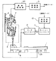
図1は、この発明の第1の実施の形態の構成を示すブロック図である。図において1は鍵であり、3は鍵1の運動をハンマ2に伝達するアクションである。4は、ハンマ2によって打弦される弦であり、5は鍵1を駆動するソレノイドである。ソレノイド5には、プランジャの位置を検出するセンサが設けられている。そして、ソレノイド5のプランジャが突出すると、鍵1がバランスピンPを中心に回動し、その演奏者側が下がり(以下、この状態を押鍵状態という)、また、これに連動してアクション3が作動し、ダンパー6が弦4から離れるとともに、ハンマ2が回動して打弦する。一方、演奏者が弾く場合は、指で鍵1を押下することにより、上述と同様の作用が生じて打弦が行われる。
【0014】
また、図において、SE1,SE2は、打弦速度を計測するためのセンサであり、演奏記録部30は、ハンマ2がこれらのセンサSE1,SE2の間を通過する時間を計測することにより、ハンマ2の速度、すなわち、打弦速度を計測し、また、ハンマ2がセンサSE1を通過する時刻を打弦時刻として検出する。なお、ハンマ2が実際に打弦する時刻にセンサSE1で検出される打弦時刻をより近づけるために、センサSE1はハンマ2の打弦位置に近接した位置に設けられている。
次に、図に示す26は、鍵1の下面に取り付けられた板状のシャッタである。25は、上下方向に所定距離隔て設けられる2組のフォトセンサによって構成されているキーセンサであり、鍵1が押下され始めると、まず上方のフォトセンサが遮光され、次いで、下方のフォトセンサが遮光される。離鍵の際には、下方のフォトセンサが受光状態になり、ついで、上方のセンサが受光状態になる。
【0015】
キーセンサ25の出力信号は、演奏記録部30に供給され、演奏記録部30は、キーセンサ25内の下方のフォトセンサが受光状態になってから上方のフォトセンサが受光状態になるまでの時間を測定し、ここから、離鍵速度を検出する。また、演奏記録部30は上方のフォトセンサが受光状態になった時刻を離鍵時刻として検出する。
【0016】
すなわち、演奏記録部30は、演奏が開始されると、センサSE1,SE2の出力信号に基づいて、打弦時刻および打弦速度を検出し、かつ、キーセンサ25の出力信号に基づいて離鍵時刻および離鍵速度を検出する。以上のようにして検出された各情報は、記録後処理部31に供給される。
【0017】
記録後処理部31においては、演奏記録部30から供給される各種情報に対し、正規化処理を施した後に、外部の記録媒体に演奏情報として供給する。ここで、正規化処理とは、ピアノの個体差を吸収するための処理である。すなわち、打弦速度、打弦時刻、離鍵速度、離鍵時刻等は、各ピアノにおけるセンサの位置や、構造上の違い、あるいは機械的誤差によって固有の傾向を持つため、標準となるピアノを想定し、そのピアノにおける打弦速度、打弦時刻等に変換するための処理である。
【0018】
10は再生前処理部であり、記録メディアあるいはリアルタイム通信装置から供給される演奏データに基づいて、鍵の軌道データを作成するとともに軌道データを用いて鍵の位置データ(t,X)を作成する回路であり、後述する制御原理に基づいて動作する。
再生前処理部10で作成された位置データ(t,X)は、モーションコントローラ11に供給される。モーションコントローラ11は、供給された位置データ(t,X)に基づいて、各時刻における鍵1の位置に対応した位置制御データ(X)を作成し、サーボコントローラ12に供給する。
サーボコントローラ12は、位置制御データ(X)に応じた励磁電流をソレノイド5に供給するとともに、ソレノイド5から供給されるフィードバック信号と制御データ(X)を比較し、両者が一致するようにサーボ制御を行う。
【0019】
(ロ)軌道作成の原理
次に、本実施形態における再生前処理部10における軌道作成の原理について説明する。
▲1▼リファレンスポイント
鍵1を押し下げる速度に応じてハンマ2の打弦速度が決まるが、鍵1の速度は初め遅くて次第に早くなる場合や、その逆の場合もあり、さらには、ほとんど一定の速さで押される場合もある。この場合、鍵1のレスト位置からエンド位置に至るまでの速度と、ハンマ2の打弦速度とがどのような関係になっているのかが重要である。なぜならば、その関係を考察せず、打弦強度データに応じて鍵速度(初期速度など)を制御しても、記録時の打弦速度を再生することはできないからである。
【0020】
実験によれば、鍵1のある位置における速度とハンマ2の打弦速度とが極めて良い対応を示すことが判った。この位置は、ピアノの個体差にもよるが、概ねレスト位置から9.0mm〜9.5mm程度押し下げた位置であった。したがって、鍵1がこの位置に達するときの速度を、打弦強度データに応じて制御すれば、記録時の打弦速度を忠実に再現することができる。なお、以下においては、上述の所定位置をリファレンスポイントXrという。
【0021】
▲2▼リファレンス速度
次に、上述のようにして求めたリファレンスポイントXrにおいて、どのような鍵速度にすれば、打弦速度を忠実に再現することができるかを設定する必要がある。なお、以下においては、リファレンスポイントXrにおける鍵速度をリファレンス速度Vrという。
【0022】
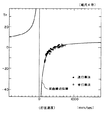
ここで、図2はリファレンスポイントXrを9.5mmに設定したときの鍵速度と打弦速度の関係を示す図である。図中、白点は鍵をエンド位置まで押し切る単打奏法を行った場合の結果を示し、黒点は鍵をエンド位置まで押し切らずに連打する連打奏法を行った場合の結果を示している。また、C1は1次最小自乗法近似による直線、C2は6次最小自乗法による曲線を示している。
【0023】
図2から明らかなように、リファレンス速度Vrは、直線C1あるいは曲線C2のいずれによっても近似できる。したがって、近似性のよい関数を適宜選択すれば、この関数を用いて任意の打弦強度データ(記録時の打弦速度情報)からリファレンス速度Vrを決定することができる。
この実施形態においては、計算が簡単で誤差の少ない1次関数近似を採用している。したがって、リファレンス速度Vrは、次式によって求められる。
【0024】
【数1】
![]()
【0025】
▲3▼リファレンス時間差
さて、演奏情報に含まれる打弦時刻データは、前述したように、相対時刻あるいは絶対時刻で記録されているが、いずれにしても再生側自動ピアノにおいて打弦時刻データを読みとって処理することにより、再生時の各音の打弦絶対時刻が求められる。そこで、このようにして求めた打弦絶対時刻において正確に打弦を行わせるには、鍵が何時リファレンスポイントXrを通過すればよいかを求める必要がある。
【0026】
ここで、鍵1がリファレンスポイントXrを通過する時刻(以下、リファレンス時刻trという)と打弦時刻(正確には、ハンマが打弦位置直前にあるセンサSE1を通過した時刻)との時間差をリファレンス時間差Trと定義し、これと打弦速度との関係を実験により求めたものが図3である。図3において、白点は単打奏法による結果、黒点は連打奏法による結果を示している。そして、図3を縮尺2倍にしたものが図4であり、縮尺4倍にしたものが図5である。これらの図から判るように、リファレンス時間差Trと打弦速度との関係は、双曲線により極めて良好に近似される。すなわち、このリファレンス時間差Trは、打弦速度VHを分母にする1変数式で近似することができ、次式によって算出される。
【0027】
【数2】
![]()
【0028】
さて、数2によって、リファレンス時間差Trが求まれば、再生側の打弦絶対時刻からリファレンス時間差Trを減算することによって、リファレンス時刻trが求められ、結局、上述した▲1▼、▲2▼、▲3▼の処理により、リファレンスポイントXr、リファレンス速度Vr、およびリファレンス時刻trが求められる。したがって、リファレンス時刻trにリファレンスポイントXrに達し、かつ、その時の速度がリファレンス速度Vrとなるように鍵1を駆動すれば、記録時の打弦状態を忠実に再現することができる。
なお、鍵1がリファレンスポイントXrに達したときに打弦が行われるのであれば、リファレンス時間差Trを求める処理は不要になる。
【0029】
▲4▼押鍵時の軌道データ作成
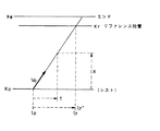
図6は、鍵の押鍵軌道を示す図であり、レスト位置X0から等速運動をしてエンド位置Xeに至っている。ここで、鍵の初速度をV0、鍵の位置をX、鍵の駆動開始時点からの時間をtとすれば、鍵の軌道は、
【0030】
【数3】
![]()
また、鍵がリファレンスポイントXrに達する時刻をtr’とすると、
【0031】
【数4】
![]()
【0032】
【数5】

上記数5によって押鍵開始時刻t0を求め、この時刻から、数3で示される軌道に従って鍵1を駆動すれば、鍵1は、リファレンス時刻trにおいて正確にリファレンスポイントXrに達し、しかも、その時の速度は、打弦強度データに対応したレファレンス速度Vrとなる。
【0033】
なお、鍵の挙動については、直線軌道(等速運動)を想定しているから、リファレンス速度Vrと初速度V0は等しい。そして、リファレンス速度Vrは、前述の数1によって求められるから、結局、数5で求めた押鍵開始時刻t0から一定速度vrで鍵を駆動するように制御(速度制御)することができる。
【0034】
▲5▼離鍵時の軌道データ作成
次に、離鍵時の軌道データ作成について説明する。
まず、鍵の位置をXN、離鍵初速度をV0N(<0)、離鍵開始時点からの時間をtN、エンド位置をXeとすれば、離鍵時の鍵軌道は、次式で表される。
【0035】
【数6】
![]()
さて、前述のように、演奏記録部30(図1参照)は、キーセンサ25内の下方のフォトセンサが受光状態になってから上方のフォトセンサが受光状態になるまでの時間を測定して離鍵速度VkNを検出し、また、上方のフォトセンサが受光状態になった時刻を離鍵時刻tkNとして検出する。この場合、離鍵時刻tkNにおけるダンパ6は、弦4に接して音の減衰を開始する状態なっている(そのような状態になるようフォトセンサの位置が調整されている)。そして、このようにして検出された離鍵速度VkNおよび離鍵時刻tkNは、それぞれ演奏情報を構成するデータとして記録され、再生時に読み出される。
【0036】
ここで、ダンパ6が弦4に接するときの鍵の位置を離鍵リファレンスポイントXrNと定義すれば、鍵1が離鍵リファレンスポイントXrNに達したときに、離鍵状態になったということができる。したがって、鍵1が離鍵リファレンスポイントXrNに達する時刻(以下、離鍵リファレンス時刻trNという)と、演奏情報中の離鍵時刻tkNとが一致するように鍵位置を制御すれば、正確な離鍵タイミング制御を行うことができる。
【0037】
また、ダンパ6が弦4に接する速さは、音の減衰状態に影響を与えるから、これを忠実に再現することが望ましい。この速さは、離鍵速度VkNに対応するから、結局、離鍵リファレンスポイントXrNにおける鍵速度(以下、離鍵リファレンス速度VrNという)を正確に離鍵速度VkNに一致させれば、音の減衰状態が正確に再現される。
ここで、鍵の駆動が開始される時刻を基準(=0)にして、鍵が離鍵リファレンスポイントXrNに達する時刻をtrN’とすると、
【0038】
【数7】
![]()
なる関係が成り立ち、この数7より時刻trN’を求めることができる。したがって、次式によって離鍵開始時刻t0Nを求めることができる。
【0039】
【数8】
なお、時刻t0から速度V0N(=VkN:離鍵速度)で鍵駆動するように制御(速度制御)しても上記と同様の結果を得ることができる。
【0040】
▲6▼押鍵スローダウン・離鍵スローアップ軌道データ作成
(a)トランジット位置
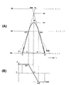
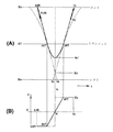
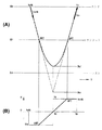
上述のようにして作成される押鍵軌道および離鍵軌道は直線状をなす等速軌道であり、以下、これらをそれぞれ押鍵等速軌道、離鍵等速軌道と称する。ここで、押鍵から離鍵へ移る演奏がハーフストロークで行われた場合には、押鍵等速軌道と離鍵等速軌道は、図8(A)に示すように、エンド位置Xeに至る手前で交差する。この自動ピアノでは、押鍵の際には、レスト位置X0から所定位置XTまでは押鍵等速軌道に基づいて鍵1を制御し、所定位置XTとエンド位置Xeの間の範囲では、2次曲線の軌道(以下、押鍵スローダウン軌道と称する)に基づいて鍵1を制御する。また、離鍵の際には、所定位置XTからレスト位置X0までは離鍵等速軌道に基づいて鍵1を制御し、所定位置XTとエンド位置Xeの範囲では、2次曲線の軌道(以下、離鍵スローアップ軌道と称する)に基づいて鍵1を制御する。なお、以下の説明においては、「所定位置」をトランジット位置と称する。また、押鍵等速軌道がトランジット位置XTに達する時刻を押鍵中間時刻(tPT)、離鍵等速軌道がトランジット位置XTから開始する時刻を離鍵中間時刻(tNT)と称する。
ここで、トランジット位置XTは、鍵1に自然な動作を与えるべく適宜設定されるが、押鍵等速軌道が短すぎると、打鍵速度の再現性を不安定にする。よって、押鍵から離鍵へ移る演奏の場合には、トランジット位置XTは、レスト位置X0とエンド位置Xeの中間よりもエンド位置Xe寄りにする。
【0041】
(b)等速時交差時刻tcの計算
図8(A)に示すように、押鍵等速軌道および離鍵等速軌道どうしが交差する位置(以下、等速時交差位置と称する)をXcとし、等速時交差位置Xcに達する時刻(以下、等速時交差時刻と称する)をtcとすると、この交差時刻tcは、押鍵等速軌道および離鍵等速軌道の軌道データから計算により求めることができる。そこで、等速時交差時刻tcに鍵の速度が0となるように、押鍵スローダウン軌道および離鍵スローアップ軌道を設定すれば、図8(B)に示すように、押鍵スローダウン軌道においては、押鍵中間時刻tPTから等速時交差時刻tcまでの間に、鍵の速度VがV0から0まで変化するような軌道を設定すればよい。また、離鍵スローアップ軌道においては、等速時交差時刻tcから離鍵中間時刻tNTまでの間に、鍵の速度Vが0からV0N(<0)まで変化するような軌道を設定すればよい。そこで、まず、等速時交差時刻tcを以下のようにして求める。
【0042】
押鍵開始時刻t0から等速時交差時刻tcまでの時間をa、等速時交差時刻tcから離鍵等速軌道が終了する時刻t4までの時間をbとすると、下記式が成立する。
【数9】
![]()
![]()
【数11】
![]()
次に、等速時交差時刻tcは、押鍵開始時刻t0に時間aを加算すれば良いから下記式によって算出される。
【数12】
【数13】
![]()
(c)押鍵スローダウン軌道データの作成
次に、押鍵スローダウン軌道における押鍵加速度aPを下記式によって求める。
【数14】
![]()
【数15】
![]()
また、押鍵スローダウン軌道における押鍵速度Vは数14で求められるaP(<0)を用いて下記数16によって求めることができ、押鍵スローダウン軌道は、下記数17によって表すことができる。ただし、式中tは、押鍵スローダウン軌道および離鍵スローアップ軌道における絶対時刻である。
【数16】
![]()
![]()
【0046】
(d)離鍵スローアップ軌道データの作成
次に、離鍵スローアップ軌道における離鍵加速度aN(<0)を以下のようにして求める。
【数18】
![]()
【数19】
![]()
【数20】
![]()
![]()
【0047】
(d)押鍵スローダウン・離鍵スローアップ軌道データの作成判定
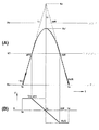
ハーフストロークで演奏が行われた場合には、押鍵等速軌道と離鍵等速軌道とが交差し、押鍵スローダウン軌道と離鍵スローアップ軌道は交差位置Xc’で交差する。また、図9(A)に示すように、押鍵等速軌道と離鍵等速軌道は交差しないが、押鍵スローダウン軌道と離鍵スローアップ軌道を作成したときに両者が交差する場合がある。さらに、図9(A)において交差位置Xc’がエンド位置Xeを越えた位置に存する場合には、押鍵スローダウン軌道と離鍵スローアップ軌道は交差しない。
【0048】
このように、離鍵等速軌道と押鍵等速軌道とが交差しない場合には、押鍵スローダウン軌道と離鍵スローアップ軌道が交差する場合と交差しない場合が生じる。この自動ピアノにおいては、前者の場合に押鍵スローダウン軌道と離鍵スローアップ軌道の軌道データを作成し、後者の場合には軌道データを作成しないこととしている。その結果、押鍵スローダウン軌道と離鍵スローアップ軌道とが交差しない場合には、鍵は離鍵等速軌道と押鍵等速軌道の軌道データに基づいて制御される。すなわち、図6および図7に示す軌道によって押鍵と離鍵とが行われる。このように、押鍵スローダウン軌道と離鍵スローアップ軌道が交差するか否かにより、作成すべき軌道データが異なってくるため、交差するか否かを以下の方法により判定する。
【0049】
まず、押鍵等速軌道と離鍵等速軌道とが交差すれば、押鍵スローダウン軌道と離鍵スローアップ軌道は交差する。よって、押鍵等速軌道と離鍵等速軌道が交差するか否かによって上記軌道が交差するか否かを判定することができる。この判定には以下の3種類の方法があり、いずれの方法を採用しても良い。
▲1▼まず、等速時交差位置Xcがエンド位置Xeよりも内側(レスト位置X0側)にあれば、押鍵スローダウン軌道と離鍵スローアップ軌道は交差する。
よって、「等速時交差位置Xc<エンド位置Xe」であれば、押鍵スローダウン軌道と離鍵スローアップ軌道が交差すると判定する。なお、等速時交差位置Xcは下記式により算出される。
【数22】
![]()
【0050】
▲2▼押鍵等速軌道がエンド位置Xeに達する時刻t3が離鍵開始時刻t0Nよりも遅ければ、これら2つの軌道は交差する。
よって、「離鍵開始時刻t0N<時刻t3」であれば押鍵スローダウン軌道と離鍵スローアップ軌道が交差すると判定する。
▲3▼押鍵等速軌道がエンド位置Xeに達する時刻t3よりも等速時交差時刻tcが早ければ、押鍵等速軌道と離鍵等速軌道は交差する。
よって、「等速時交差時刻tc<時刻t3」ならば押鍵スローダウン軌道と離鍵スローアップ軌道が交差すると判定する。なお、「離鍵開始時刻t0N<等速時交差時刻tc」の場合にも交差すると判定することができる。
【0051】
次に、上記いずれの条件も満たさない場合には、以下のいずれかの方法により押鍵スローダウン軌道と離鍵スローアップ軌道が交差するか否かを判定する。
▲1▼まず、上述の交差位置Xc’は、等速時交差位置Xcとトランジット位置XTの中央に位置するので、下記式によって求めることができる。
【数23】
【0052】
▲2▼次に、押鍵スローダウン軌道と離鍵スローアップ軌道とが交差するか否かの臨界条件を考えると、それは、図9(A)において交差位置Xc’がエンド位置Xeと一致する状態であり、この場合には、押鍵スローダウン軌道と離鍵スローアップ軌道の押鍵速度Vがともにエンド位置Xeで0になる。ここで、数17で表される押鍵スローダウン軌道と数21で表される離鍵スローアップ軌道は、等速時交差時刻tcで傾きが0となる2次曲線であるが、エンド位置Xeで傾きが0となる2次曲線を押鍵スローダウン軌道と離鍵スローアップ軌道速度についてそれぞれ想定する。すなわち、図10(A)に示すように、エンド位置Xeに時刻tPE’に達して押鍵速度Vが0になる押鍵スローダウン軌道と、時刻tNE’にエンド位置Xeで開始する離鍵スローアップ軌道を想定すると、図10(A)に示す状態は、押鍵スローダウン軌道と離鍵スローアップ軌道とが交差しない場合に含まれる。
【0053】
そこで、「時刻tNE’<時刻tPE’」ならば、押鍵スローダウン軌道と離鍵スローアップ軌道が交差すると判定する。なお、時刻tPE’およびtNE’は、下記式で求めることができる。
【数24】
![]()
![]()
▲3▼「等速時交差時刻tc<時刻tPE’」ならば、押鍵スローダウン軌道と離鍵スローアップ軌道が交差すると判定する。なお、「時刻tNE’<等速時交差時刻tc」のときに、押鍵スローダウン軌道と離鍵スローアップ軌道が交差すると判定することもできる。
以上が再生前処理部10における軌道データの作成原理である。
【0055】
(ハ)第1の実施の形態の動作
始めに、記録動作について説明する。まず、演奏者によって演奏が行われると、演奏記録部30がセンサSE1,SE2の出力信号に基づいて打弦速度および打弦時刻を検出するとともに、センサ25の出力信号に基づいて離鍵時刻および離鍵速度を検出する。これらの情報は、記録後処理部31において正規化処理された後に、演奏情報としてフロッピーディスク等の記録媒体に記録される。
【0056】
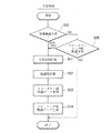
次に、再生動作について図11および図12を参照して説明する。まず、再生前処理部10は、記録媒体から演奏情報を読み出すか、あるいは、外部から供給される演奏情報を受信し、その中に打弦イベントの演奏情報が含まれるか否かを判定する(ステップS1)。そして、打弦イベントの演奏情報が含まれる場合には、ステップS1での判定結果は「YES」となり、ステップS2へ進んで数3に示す押鍵等速軌道の軌道データを作成する。押鍵等速軌道は、レスト位置X0からエンド位置Xeに至る軌道であり、この軌道データは、演奏情報である打弦時刻データおよび打弦速度データに基づいて作成される。なお、ステップS1においては、打弦イベントの演奏情報を受信するまでその有無の判定を繰り返す。
【0057】
次に、ステップS3へ進み、打弦イベントの後に続く離鍵イベントの演奏情報を受信しているか否かを判定する。すなわち、再生前処理部10は、演奏情報を受信してから所定時間(例えば0.5秒)の間に、軌道データを作成するようになっている。よって、打弦イベントの演奏情報の受信と離鍵イベントの演奏情報の受信との時間差によっては、押鍵等速軌道の軌道データを作成した際に、これと対になる離鍵イベントの演奏情報が受信されていない場合が生じる。この場合には、前述の方法によっては押鍵スローダウン軌道や離鍵スローアップ軌道の軌道データを作成することはできない。このため、ステップ3においては、所定時間内に押鍵イベントと対になる離鍵イベントが受信されたか否かを判定するようにしている。そして、該当する離鍵イベントの受信があった場合には、ステップS4へ進んで数6に示す離鍵等速軌道の軌道データを作成する。
【0058】
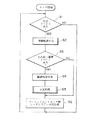
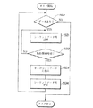
次に、ステップS5へ進んで押鍵スローダウン軌道と離鍵スローアップ軌道を作成するための交差処理を行う。図12は交差処理を示すサブルーチンであって、まず、ステップS2およびS4において作成した押鍵等速軌道と離鍵等速軌道とが交差するか否かを判定する(ステップS10)。演奏がハーフストロークで行われた場合には、これら2つの軌道は交差し、ステップS10での判定結果は「YES」となる。この場合には、ステップS11へ進んで上記2つの軌道の等速時交差時刻tcを数12を用いて計算する。次いで、ステップS12へ進み、押鍵スローダウン軌道および離鍵スローアップ軌道における加速度aP,aNを数14および数18を用いて計算する。そして、求めた加速度aP,aNを用いて、数17および数21に示す押鍵スローダウン軌道と離鍵スローアップ軌道の軌道データを作成する(ステップS13およびS14)。
【0059】
一方、押鍵と離鍵とがフルストロークで行われた場合には、押鍵等速軌道と離鍵等速軌道とは交差しない。この場合には、ステップS10での判定結果は「NO」となり、ステップS15へ進んで押鍵スローダウン軌道と離鍵スローアップ軌道が交差するか否かを判定する。そして、押鍵スローダウン軌道と離鍵スローアップ軌道が交差すると判定した場合には、上述したステップS11〜S14の処理を行って押鍵スローダウン軌道と離鍵スローアップ軌道の軌道データを作成する。以上の処理により押鍵スローダウン軌道と離鍵スローアップ軌道の軌道データを作成すると、図11に示すルーチンに戻る。そして、ステップS6へ進み、モーションコントローラ11に供給する位置データ(t,X)を作成する。なお、ステップS15において、押鍵スローダウン軌道と離鍵スローアップ軌道が交差しないと判定した場合には、ステップS11〜S14の処理を行わずに図11に示すルーチンに戻る。
【0060】
ステップS6において作成する位置データ(t,X)は、時刻tと、時刻tに対応する鍵の位置Xからなる。ここで、時刻tは、押鍵開始時刻t0から離鍵が終了する時刻t4までを一定のピッチで刻んだ時刻である。あるいは、押鍵スローダウン軌道と離鍵スローアップ軌道における時刻tのピッチを短くし、押鍵等速軌道および離鍵等速軌道における時刻tのピッチを長くすることもできる。このようにして時刻tのピッチを設定することにより、押鍵等速軌道および離鍵等速軌道における位置データ(t,X)の計算を簡略化し、かつ、押鍵スローダウン軌道と離鍵スローアップ軌道における鍵1の動作を正確かつ滑らかにすることができる。
【0061】
また、鍵の位置Xは、前述の方法によって求めた各軌道データに各時刻tを代入して求める。すなわち、押鍵開始時刻t0から押鍵中間時刻tPTまでは、時刻tを数3に代入して押鍵等速軌道における鍵1の位置Xを求め、押鍵中間時刻tPTから等速時交差時刻tcまでは、時刻tを数17に代入して押鍵スローダウン軌道における鍵の位置Xを求める。また、等速時交差時刻tcから離鍵中間時刻tNTまでは、時刻tを数21に代入して離鍵スローアップ軌道における鍵の位置Xを求め、離鍵中間時刻tNTから時刻t4までは、時刻tを数6に代入して離鍵等速軌道における鍵の位置Xを求める。そして、こうして作成した位置データ(t,X)を、再生前処理部10に設けたメモリの所定のアドレスから時刻tの順番に格納する。このように、メモリの所定のアドレスから時刻tの順番に位置データ(t,X)を格納することにより、押鍵開始から離鍵終了までの鍵の位置Xを時刻t毎に求めたシーケンシャルデータ列を作成する。なお、打弦イベントの後に続く離鍵イベントの演奏情報を受信していない場合には、ステップS3での判定結果は「NO」となり、ステップS6へ進んで押鍵等速軌道の位置データ(t,X)のみをメモリに格納する。
【0062】
次に、モーションコントローラ11の処理を図13を参照して説明する。まず、再生前処理部10のメモリに位置データ(t,X)が存在するか否かを判定し(ステップS20)、位置データ(t,X)が存在する場合には、ステップS21へ進んで再生前処理部10のメモリに格納されたシーケンスデータ列のうち、先頭アドレスの位置データ(t,X)を読み出す。モーションコントローラ11は、位置データ(t,X)を読み出すと、ステップS22に進んで現在の時刻が位置データ(t,X)に示す時刻t(この場合、時刻tは押鍵開始時刻t0である)であるか否かを判定する。
【0063】
そして、モーションコントローラ11は、押鍵開始時刻t0に達するまで位置データ(t,X)の読出しを繰り返し(ステップS21,S22)、押鍵開始時刻t0に達すると、ステップS23へ進んで、位置データ(t,X)に示された鍵の位置Xに対応する位置制御データ(X)をサーボコントローラ12に供給する。これにより、鍵の位置Xに対応した励磁電流がソレノイド5に供給される。この場合、サーボコントローラ12は、ソレノイド5のプランジャ(図示略)に設けた位置センサから供給されるフィードバック信号と位置制御データ(X)とを比較し、両者が一致するように励磁電流を制御する。次に、ステップS24へ進み、シーケンスデータ列の次のアドレスにアクセスする。そして、上記ステップ20〜S24を繰り返してソレノイド5のプランジャを突出させてゆく。これにより、ソレノイド5のプランジャの突出量は、数3のXに対応したものとなり、鍵1は押鍵等速軌道に従って制御される。
【0064】
ここで、押鍵スローダウン軌道と離鍵スローアップ軌道の軌道データが作成された場合には、押鍵中間時刻tPT以後にシーケンシャルデータ列から読み出される位置データ(t,X)は、数17で求めたものとなる。このため、サーボコントローラ12は、ソレノイド5のプランジャを数17に示される2次曲線の押鍵スローダウン軌道に従って突出させてゆく。これにより、鍵1は押鍵スローダウン軌道に従って制御される。また、等速時時刻tcに達すると、読み出される位置データ(t,X)は、数21で求めたものとなる。このため、サーボコントローラ12は、ソレノイド5のプランジャを数21に示される2次曲線の離鍵スローアップ軌道に従って縮小させてゆく。これにより、鍵1は離鍵スローアップ軌道に従って制御される。
【0065】
次に、離鍵中間時刻tNTに達すると、読み出される位置データ(t,X)は数6により求めたものとなるため、サーボコントローラ12は、ソレノイド5のプランジャを数6に示される離鍵等速軌道に従って縮小させてゆく。これにより、鍵1は離鍵等速軌道に従って制御される。
こうして離鍵等速軌道が終了する時刻t4に達すると、シーケンシャルデータ列の全ての位置データ(t,X)が読み出され、鍵1はレスト位置X0に達する。そして、この場合には、次にアクセスしたアドレスには位置データ(t,X)が存在しなくなるから、ステップS20における判定結果は「NO」となり、図13に示すタスクを終了する。なお、図13に示すタスクは、所定時間おきに開始されるようになっている。
【0066】
このように、上記構成の自動ピアノにあっては、鍵1の動作が押鍵から離鍵に移行する際には、鍵1の速度を徐々に変化させて鍵1の動作の方向を切り替えるから、鍵1の動作が滑らかになって違和感のない自然な動作となる。また、離鍵の際に鍵に大きな加速度が作用しないため、鍵1の動作が乱れるようなことがない。特に、上記自動ピアノにおいては、押鍵等速軌道および離鍵等速軌道が交差しないと判定された場合であっても、押鍵スローダウン軌道および離鍵スローアップ軌道が交差すると判定した場合には、押鍵スローダウン軌道および離鍵スローアップ軌道に基づいて鍵1を駆動する。このように、記録時には押鍵から離鍵へフルストロークで演奏された場合であっても、再生時には離鍵開始時の鍵1の速度が徐々に変化するから、鍵1の動作の揺らぎの発生を少なくすることができる。
【0067】
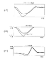
ここで、実験結果を図14に示す。同図(イ)は押鍵から離鍵までをハーフストロークで演奏した場合のソレノイドのプランジャの軌道、同図(ロ)は鍵の軌道、同図(ハ)はハンマの軌道をそれぞれ測定したものである。また、図中実線は押鍵スローダウン軌道と離鍵スローアップ軌道に従ってプランジャを駆動した場合の各軌道、一点鎖線は直線の押鍵等速軌道と直線の離鍵等速軌道が交差する交差軌道に従ってプランジャを駆動した場合の各軌道を示す。同図(ロ)から判るように、直線軌道の場合には鍵の離鍵等速軌道に矢印Yで示す乱れが生じている。これは、押鍵から離鍵への移行が急激に行われるため、鍵に弾性変形が生じたことによるものと考えられる。一方、押鍵スローダウン軌道と離鍵スローアップ軌道に従ってプランジャを駆動した場合には、離鍵等速軌道にそのような乱れはなく、鍵はスムーズな動きを示している。また、同図(ハ)に示すように、押鍵の初速度があまり変わらない場合には、直線軌道の場合も押鍵スローアップ・スローダウン軌道の場合もハンマの軌道はあまり変わらないことも確認された。
【0068】
B.第2の実施の形態
図15ないし図17を参照して本発明の第2の実施の形態について説明する。第2の実施の形態は、離鍵から押鍵に移る演奏において本発明を適用した例である。
(a)トランジット位置
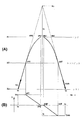
離鍵から押鍵へ移る演奏がハーフストロークで行われる場合には、図15(A)に示すように、離鍵等速軌道と押鍵等速軌道はレスト位置X0に至る手前で交差する。この実施の形態では、エンド位置Xeからトランジット位置XTまでは離鍵等速軌道に基づいて鍵1を制御し、トランジット位置XTとレスト位置X0の間の範囲では、2次曲線の軌道(以下、離鍵スローダウン軌道と称する)に基づいて鍵1を制御する。また、押鍵の軌道については、所定位置XTからエンド位置Xeまでは押鍵等速軌道に基づいて鍵1を制御し、所定位置XTとレスト位置X0の間の範囲では、2次曲線の軌道(以下、押鍵スローアップ軌道と称する)に基づいて鍵1を制御する。
【0069】
トランジット位置XTの位置は、押鍵から離鍵に移る演奏の場合よりもレスト位置X0側に設定される。これは、トランジット位置XTがエンド位置Xe側に寄りすぎていると、離鍵スローダウン軌道と押鍵スローアップ軌道の交差位置Xc’もエンド位置Xe側へ寄り過ぎになってしまうため、エンド位置Xe寄りで連打を行うと、鍵1がレスト位置X0側へ戻る距離が短いために押鍵時にアクション3がハンマ2に係合せず、演奏が行えないという事態が生じるからである。さらに、離鍵開始後、鍵1がエンド位置Xeから所定距離離れたときにダンパ6が当該鍵1に対応する弦4を押すように構成されているが、エンド位置Xeに近い箇所から離鍵スローダウン軌道が開始すると、ダンパ6が弦4を押すタイミングが遅くなってしまうからである。よって、以上の点を考慮してトランジット位置XTの位置は設定され、具体的にはレスト位置X0とエンド位置Xeのほぼ中間とされる。
【0070】
(b)交差時刻tcの計算
この自動ピアノにおいても、等速時交差時刻tcに鍵1の速度が0となるように離鍵スローダウン軌道および押鍵スローアップ軌道を設定する。そして、離鍵スローダウン軌道においては、離鍵中間時刻tNTから等速時交差時刻tcまでの間に、鍵1の速度VがV0N(<0)から0まで変化するような軌道を設定する。また、押鍵スローアップ軌道においては、等速時交差時刻tcから押鍵中間時刻tPTまでの間に、鍵1の速度Vが0からV0まで変化するような軌道を設定する。そのために、交差時刻tcを以下のようにして求める。
【数26】
![]()
【数27】
![]()
(c)離鍵スローダウン軌道データの作成
次に、離鍵スローダウン軌道における離鍵加速度aNを以下のようにして求める。
【数28】
![]()
【数29】
![]()
![]()
【0072】
(d)押鍵スローアップ軌道データの作成
次に、押鍵スローアップ軌道における押鍵加速度aPを以下のようにして求める。
【数31】
![]()
【数32】
![]()
![]()
【0073】
(d)離鍵スローダウン・押鍵スローアップ軌道データの作成判定
まず、押鍵等速軌道と離鍵等速軌道とが交差するか否かによって離鍵スローダウン軌道と押鍵スローアップ軌道が交差するか否かを判定する。この判定には以下の3種類の方法があり、いずれの方法を採用しても良い。
▲1▼まず、等速時交差位置Xcがレスト位置X0よりも内側(エンド位置Xe側)にあれば、離鍵スローダウン軌道と押鍵スローアップ軌道は交差する。
よって、「レスト位置X0<等速時交差位置Xc」であれば、離鍵スローダウン軌道と押鍵スローアップ軌道が交差すると判定する。なお、等速時交差位置Xcは下記式により算出される。
【数34】
![]()
(2)離鍵等速軌道がレスト位置X0に達する時刻t4が押鍵開始時刻t0よりも遅ければ、これら2つの軌道は交差する。
よって、「押鍵開始時刻t0<時刻t4」であれば押鍵スローアップ軌道と離鍵スローダウン軌道が交差すると判定する。
(3)離鍵等速軌道がレスト位置X0に達する時刻t4よりも等速時交差時刻tcが早ければ、押鍵等速軌道と離鍵等速軌道は交差する。よって、「等速時交差時刻tc<時刻t4」ならば押鍵スローアップ軌道と離鍵スローダウン軌道が交差すると判定する。なお、「時刻t0<等速時交差時刻tc」の場合にも交差すると判定することができる。
【0075】
次に、上記いずれの条件も満たさない場合には、以下のいずれかの方法により押鍵スローダウン軌道と離鍵スローアップ軌道が交差するか否かを判定する。
▲1▼離鍵スローダウン軌道と押鍵スローアップ軌道の交差位置Xc’は下記式によって求めることができる。
【数35】
【0076】
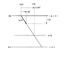
▲2▼レスト位置X0で傾きが0となる2次曲線を離鍵スローダウン軌道と押鍵スローアップ軌道速度についてそれぞれ想定する。すなわち、図17(A)に示すように、レスト位置X0に時刻tNR’に達して押鍵速度Vが0になる離鍵スローダウン軌道と、時刻tPR’にレスト位置X0で開始する押鍵スローアップ軌道を想定すると、図17(A)に示す状態は、押鍵スローダウン軌道と離鍵スローアップ軌道とが交差しない場合に含まれる。
そこで、「時刻tNR’>時刻tPR’」ならば、スローアップ軌道とスローダウン軌道は交差すると判定する。なお、時刻tNR’およびtPE’は、近似的に下記式で求めることができる。
【数36】
![]()
![]()
【0077】
上記構成の自動ピアノは、図11ないし図13に示すものと同様のアルゴリズムに従って動作する。この場合において、図11のステップS1では「離鍵イベントの有無」を判定し、ステップS2では離鍵等速軌道の軌道データを作成する。また、ステップS3では「その後の打弦イベントの有無」を判定し、ステップS4では押鍵等速軌道の軌道データを作成する。したがって、離鍵から押鍵に移る演奏がハーフストロークで行われた場合には、離鍵等速軌道→離鍵スローダウン軌道→押鍵スローアップ軌道→押鍵等速軌道という順番で鍵1が制御され、鍵1に違和感のない自然な動作を与えることができる。
【0078】
特に、この実施の形態においては、離鍵から押鍵に移る演奏に本発明を適用しているから、押鍵の際の鍵に勢いが生じて音量が打弦強度データが示す値よりも大きくなったり、一部の打弦に抜けが生じたり、打弦のタイミングがずれてリズムが乱れたりするといった不都合が生じない。また、鍵の動作が演奏者による演奏に近いから、エンド位置近くで連打を行ったときの発音の響きを忠実に再現することができる。
【0079】
さらに、離鍵等速軌道および押鍵等速軌道が交差しないと判定された場合であっても、離鍵スローダウン軌道および押鍵スローアップ軌道が交差すると判定した場合には、押鍵スローアップ軌道および離鍵スローダウン軌道に基づいて鍵1を駆動するから、記録時にはフルストロークによる離鍵から押鍵に移る演奏を行った場合であっても、再生時には押鍵開始時の鍵1の速度が徐々に変化するから、鍵1の動作の揺らぎを少なくすることができる。
なお、押鍵から離鍵に移る場合の鍵1の制御(第1の実施の形態)と、離鍵から押鍵に移る場合の鍵1の制御(第2の実施の形態)とに分けて説明したが、これら2種類の制御を行う自動ピアノを構成することもできる。
【0080】
C.変形例
(1)第1の実施の形態において、押鍵スローダウン軌道と離鍵スローアップ軌道が交差しないと判定された場合も両軌道データを作成して鍵1を制御することができる。この場合には、図10(B)に示すように、押鍵スローダウン軌道においては、押鍵中間時刻tPTから時刻tPE’の間に鍵1の速度VをV0から0まで変化させる。よって、押鍵スローダウン軌道における押鍵加速度aPは下記式により求めることができる。なお、時刻tPE’は、数24によって求めることができる。
【数38】
![]()
また、離鍵スローアップ軌道においては、時刻tNE’から離鍵中間時刻tNTまでの間に鍵1の速度Vを0からV0Nまで変化させる。よって、離鍵スローアップ軌道における離鍵加速度aNは下記式により求めることができる。なお、時刻tNE’は、数18〜数21を用いてtを解とする2次方程式を作成することにより求めることができ、また、数25によっても求めることができる。
【数39】
![]()
【0082】
なお、第2の実施の形態において、離鍵スローダウン軌道と押鍵スローアップ軌道が交差しないと判定された場合も、両軌道データを作成して鍵1を制御することができる。この場合には、図17(B)に示すように、離鍵スローダウン軌道においては、離鍵中間時刻tNTから時刻tNR’の間に鍵1の速度VをV0Nから0まで変化させる。また、押鍵スローアップ軌道においては、時刻tPR’から押鍵中間時刻tPTまでの間に鍵1の速度Vを0からV0まで変化させる。
【0083】
(2)前記各実施の形態では押鍵軌道と離鍵軌道を等速軌道としたが、図8(A)および図15(A)に一点鎖線で示すように、2次曲線をなす軌道にすることができる。この場合には、押鍵軌道を以下のように表す。
【数40】
![]()
このような押鍵軌道と離鍵軌道に従って鍵1を制御することにより、演奏者の演奏により近い動作を鍵1に与えることができる。
【0084】
(3)前記実施の形態では、短縮軌道として2次曲線の軌道を作成したが、短縮軌道は、押鍵等速軌道と離鍵直線軌道の交差点に達しない軌道であればその種類は任意である。たとえば、円軌道や楕円軌道、あるいは折れ線状に屈曲するような軌道であってもよい。
(4)押鍵を押鍵等速軌道に従って行い、押鍵に続く離鍵を離鍵スローアップ軌道に従って行うことができ、また、押鍵を押鍵スローダウン軌道に従って行い、押鍵に続く離鍵を離鍵等速軌道に従って行うこともできる。さらに、離鍵を離鍵等速軌道に従って行い、離鍵に続く押鍵を押鍵スローアップ軌道に従って行うことができ、また、離鍵を離鍵スローダウン軌道に従って行い、離鍵に続く押鍵を押鍵等速軌道に従って行うこともできる。
(5)サーボ制御の変形
上述した各実施の形態においては、再生前処理部10により位置データ(t,X)を作成し、モーションコントローラ11とサーボコントローラ12によって位置サーボ制御を行っていたが、これに代えて、速度を指示する速度サーボ制御を行っても良い。すなわち、再生前処理部10により速度データ(t,V)のシーケンシャルデータ列を作成し、モーションコントローラ11が押鍵(あるいは離鍵)開示時刻において初速度を指示し、サーボコントローラ12が鍵1が与えられた速度を保つようにサーボ制御を行うようにしてもよい。
【0085】
(6)上述した各実施の形態は、すべてリファレンスポイントにおける運動属性を再生するように鍵を駆動する例であったが、リファレンスポイントやリファレンス速度を考慮せず、単純に押鍵と離鍵の直線軌道を作成し、これによって制御することもできる。例えば、打鍵速度から単純に押鍵の直線軌道を想定し、これに基づいて鍵をサーボ駆動することもできる。
【0086】
【発明の効果】
以上説明したように、この発明によれば、押鍵から離鍵あるいは離鍵から押鍵へ移る演奏を行う場合に、鍵の速度が急激に変化しないから、鍵の動作が滑らかになって違和感のない自然な動作を得ることができる。また、連打時の押鍵の音量が大きくなったり、打弦の抜けやリズムの狂いが生じる等の問題は解消され、連打を円滑に行うことができる。
また、記録時にはフルストロークの演奏による押鍵または離鍵を行った場合であっても、再生時には短縮軌道によって離鍵開始時または押鍵開始時に鍵の速度が徐々に変化するから、鍵の動作のゆらぎの発生を少なくすることができる。
【図面の簡単な説明】
【図1】この発明の第1実施形態の構成を示すブロック図である。
【図2】図2はリファレンスポイントを9.5mmに設定したときの鍵速度と打弦速度の関係を示す図である。
【図3】リファレンス時間差Trと打弦速度との関係を示す図である。
【図4】図3を縮尺2倍にした図である。
【図5】図3を縮尺4倍にした図である。
【図6】鍵の押鍵軌道を示す図である。
【図7】数6で示される軌道を示す図である。
【図8】離鍵軌道および鍵速度を示す図である。
【図9】離鍵軌道および鍵速度を示す図である。
【図10】鍵軌道および鍵速度を示す図である。
【図11】第1の実施の形態における再生前処理部の動作を示すフローチャートである。
【図12】第1の実施の形態における再生前処理部の動作を示すフローチャートである。
【図13】第1の実施の形態におけるモーションコントローラの動作を示すフローチャートである。
【図14】ハーフストロークにおいてプランジャ等の軌道を示す図である。
【図15】鍵軌道および鍵速度を示す図である。
【図16】鍵軌道および鍵速度を示す図である。
【図17】鍵軌道および鍵速度を示す図である。
【符号の説明】
5……ソレノイド(駆動手段)、10……再生前処理部(軌道算出手段:交差判定手段)、11……モーションコントローラ(指令値出力手段)、12……サーボコントローラ(指令値出力手段)。[0001]
TECHNICAL FIELD OF THE INVENTION
The present invention relates to an automatic piano for automatically performing a performance by driving a keyboard.
[0002]
[Prior art]
In an automatic piano, when a key is driven by exciting a solenoid, a hammer is rotated and a string is struck accordingly. The strength of the hammer striking corresponds to the driving speed of the key, and the driving speed of the key corresponds to the current supplied to the solenoid. Therefore, by controlling the amount of power supplied to the solenoid, it is possible to control the strength of the string striking, that is, the magnitude of the generated musical sound.
[0003]
In an automatic piano, when performance information is recorded, the speed of the hammer immediately before striking is detected, and this is recorded as data indicating the striking strength (hereinafter referred to as striking strength data). The time of passing the string striking position is recorded as string striking time data. Note that the string striking time data is generally recorded as time data (relative time data) indicating an interval from the immediately preceding sound, but an absolute time from the start of the performance may be recorded.
When reproducing the recorded performance information, a current corresponding to the stringing strength data in the performance information is supplied to the solenoid. Further, the power supply amount control to the solenoid is generally performed by pulse width modulation (PWM).
[0004]
In this case, power is supplied to the solenoid a little before the stringing timing indicated by the stringing time data, in anticipation of the time difference from the start of driving the key to the actual stringing of the hammer. Also, since the time from the start of key depression to the striking of a strong sound differs from that of a weak sound, an automatic piano has been developed in which the power supply timing to the solenoid is adjusted in accordance with the string striking strength data.
In the case of a key release, a key release timing is detected and recorded by a photosensor, and during reproduction, the solenoid is de-energized at a time corresponding to the key release timing.
[0005]
By the way, in the performance of a piano, a so-called half-stroke technique may be performed. In this case, a key release is started before the key is completely pressed (the key is pushed to the end position), Alternatively, the next key pressing operation is started during the key release.
[0006]
However, in a conventional automatic piano, simple control is performed such that the solenoid is excited shortly before the key-depression timing and the solenoid is de-energized shortly before the key-release timing. No consideration has been given to the reproduction of the half-stroke that is performed only up to this point. For this reason, in a portion played in a half-stroke, there is a timing shift in key press and key release, and in particular, in a continuous half-stroke, there is a problem that reproduction cannot be performed.
[0007]
Therefore, the applicant first determines whether or not a half-stroke is based on the start time and completion time of the key-release key or the intersection of the key-release key trajectory. An automatic piano capable of faithfully reproducing a half stroke by shifting to key release processing or shifting to key depression processing in the middle of key release has been proposed (Japanese Patent Application No. 5-344242).
[0008]
[Problems to be solved by the invention]
However, in the above-mentioned automatic piano, when performing with a half stroke, the operation shifts to the key release process from the middle of the key press, or to the key press process from the middle of the key release, so that the key operation speed changes rapidly. . For this reason, in particular, there is a concern that the following behavior will be exhibited when continuous hitting is performed.
{Circle around (1)} When shifting from key release to key press, the key may be rebounded. In such a case, momentum is generated in the key, and the sound volume becomes larger than the value indicated by the string striking strength data.
(2) When shifting from key release to key press, the key press may not be performed properly due to the inertia generated in the key. In such a case, some strings may be missing. And the rhythm is disturbed due to the wrong timing of the strings.
{Circle around (3)} By performing continuous tapping near the end position, a performance technique may be used in which the sound stopping by the damper is weakened and the sound of the pronunciation is increased. However, in the above-described technology, the key tends to return too much when the key is released, and the sound tends to stop more than intended.
{Circle around (4)} The appearance of the key is unnatural because the key operation is sharp.
The above is the phenomenon that is expected when performing with repeated hits.However, even when performing a full stroke performance of pressing and releasing a key between the rest position and the end position, the key operation starts suddenly. Since the operation is performed, the operation may fluctuate, and in such a case, the keying and the sound stopping may be disturbed.
The present invention has been made in view of the above-described circumstances, and provides an automatic piano that can give a natural movement to a key when performing a half-stroke performance and can smoothly perform a continuous tap. It is aimed at. Another object of the present invention is to provide an automatic piano that can suppress fluctuations in key operation when performing with full strokes.
[0009]
[Means for Solving the Problems]
In order to solve the above-mentioned problem, the invention according to
[0010]
According to a second aspect of the present invention, in the first aspect, the intersection determining means determines that the key pressing trajectory and the key releasing trajectory do not intersect. When , The shortened track reaches the end position when the key is fully pressed or the rest position when the key is not pressed Judge whether or not The command value output means, when the intersection determination means determines that the key press trajectory and the key release trajectory intersect, and when it is determined that the shortened trajectory does not reach the end position or the rest position, A corresponding command value is supplied to the driving unit, and if not, a command value corresponding to the key depression trajectory and the key release trajectory calculated by the trajectory calculation unit is supplied to the driving unit. It is characterized by:
[0011]
According to the first aspect of the present invention, when it is determined that the key-depressed trajectory and the key-release trajectory intersect, the key is driven along the shortened trajectory without passing through the intersection of the trajectories, and the key-release trajectory is shifted from the key-depressed trajectory. Alternatively, a transition is made from a key release trajectory to a key press trajectory. For this reason, the key speed does not suddenly change, and the key operation becomes smooth, so that a natural operation without a sense of incongruity can be obtained. Further, since the key speed does not change abruptly, problems such as an increase in sound volume at the time of depressing a key during repeated tapping, occurrence of missing strings, and an irregular rhythm are eliminated, and continuous tapping can be performed smoothly.
[0012]
In the invention according to
[0013]
BEST MODE FOR CARRYING OUT THE INVENTION
A: First embodiment
(B) Configuration
FIG. 1 is a block diagram showing the configuration of the first embodiment of the present invention. In the figure, 1 is a key, and 3 is an action for transmitting the movement of the key 1 to the
[0014]
In the figure, SE1 and SE2 are sensors for measuring the string striking speed, and the
Next,
[0015]
The output signal of the
[0016]
That is, when the performance is started, the
[0017]
The
[0018]
The position data (t, X) created by the
The
[0019]
(B) Principle of orbit creation
Next, the principle of trajectory creation in the
(1) Reference point
The string striking speed of the
[0020]
According to an experiment, it was found that the velocity at a certain position of the
[0021]
(2) Reference speed
Next, at the reference point Xr determined as described above, it is necessary to set what key speed should be used to reproduce the string striking speed faithfully. In the following, the key speed at the reference point Xr is referred to as a reference speed Vr.
[0022]
Here, FIG. 2 is a diagram showing the relationship between the key speed and the string striking speed when the reference point Xr is set to 9.5 mm. In the figure, the white dots indicate the results in the case of performing the single-stroke playing method in which the key is pushed to the end position, and the black dots indicate the results in the case of performing the continuous striking method in which the key is struck without pushing the key to the end position. C1 indicates a straight line based on the first-order least squares approximation, and C2 indicates a curve based on the sixth-order least squares method.
[0023]
As is apparent from FIG. 2, the reference speed Vr can be approximated by either the straight line C1 or the curve C2. Therefore, if a function having good approximation is appropriately selected, the reference speed Vr can be determined from arbitrary stringing strength data (stringing speed information at the time of recording) using this function.
In this embodiment, a linear function approximation with simple calculation and small error is adopted. Therefore, the reference speed Vr is obtained by the following equation.
[0024]
(Equation 1)
![]()
[0025]
(3) Reference time difference
As described above, the string striking time data included in the performance information is recorded as a relative time or an absolute time. In any case, the string striking time data is read and processed by the reproducing automatic piano. The absolute string striking time of each sound at the time of reproduction is obtained. Therefore, in order to accurately perform string striking at the absolute string striking time obtained in this manner, it is necessary to determine when the key should pass through the reference point Xr.
[0026]
Here, the time difference between the time when the key 1 passes through the reference point Xr (hereinafter referred to as reference time tr) and the string striking time (more precisely, the time when the hammer passes through the sensor SE1 immediately before the string striking position) is referred to. FIG. 3 shows the relationship between the time difference Tr and the string striking speed obtained by experiments. In FIG. 3, the white dots indicate the results obtained by the single hitting technique, and the black dots indicate the results obtained by the continuous playing technique. FIG. 4 is a diagram in which FIG. 3 is doubled in scale, and FIG. 5 is a diagram in which the scale is quadrupled. As can be seen from these figures, the relationship between the reference time difference Tr and the string striking speed is very well approximated by a hyperbola. That is, the reference time difference Tr can be approximated by a one-variable equation using the stringing speed VH as a denominator, and is calculated by the following equation.
[0027]
(Equation 2)
![]()
[0028]
By the way, if the reference time difference Tr is obtained by the
If the string is struck when the
[0029]
(4) Creating orbit data when key is pressed
FIG. 6 is a diagram showing a key pressing trajectory of the key, and the rest position X 0 , And reaches the end position Xe. Here, the initial velocity of the key is V 0 If the position of the key is X and the time from the start of driving the key is t, the trajectory of the key is
[0030]
(Equation 3)
![]()
When the time when the key reaches the reference point Xr is tr ′,
[0031]
(Equation 4)
![]()
[0032]
(Equation 5)
The key pressing start time t is calculated by the above equation (5). 0 From this time, if the
[0033]
Since the key behavior is assumed to be a linear trajectory (constant velocity motion), the reference velocity Vr and the initial velocity V 0 Are equal. Then, since the reference speed Vr is obtained by the
[0034]
(5) Creation of orbit data at key release
Next, creation of orbit data at the time of key release will be described.
First, the key position is XN and the initial key release speed is V 0 If N (<0), the time from the key release start time is tN, and the end position is Xe, the key trajectory at the time of key release is expressed by the following equation.
[0035]
(Equation 6)
![]()
As described above, the performance recording unit 30 (see FIG. 1) measures the time from when the lower photo sensor in the
[0036]
Here, if the position of the key when the
[0037]
Since the speed at which the
Here, assuming that the time at which the driving of the key starts is a reference (= 0) and the time at which the key reaches the key release reference point XrN is trN ′,
[0038]
(Equation 7)
![]()
The following relationship holds, and the time trN ′ can be obtained from the equation (7). Therefore, the key release start time t is given by the following equation. 0 N can be determined.
[0039]
(Equation 8)
Note that time t 0 To speed V 0 The same result as described above can be obtained by performing control (speed control) so that the key is driven at N (= VkN: key release speed).
[0040]
6) Key depression slowdown / key release slowup orbit data creation
(A) Transit position
The key depression trajectory and the key release trajectory created as described above are linear constant velocity trajectories, and these are hereinafter referred to as a key depression constant velocity trajectory and a key release constant velocity trajectory, respectively. Here, when the performance from the key press to the key release is performed in a half stroke, the key press constant velocity trajectory and the key release constant velocity trajectory reach the end position Xe as shown in FIG. Cross in front. In this automatic piano, when the key is pressed, the rest position X 0 From the predetermined position XT to the predetermined position XT, the
Here, the transit position XT is appropriately set so as to give a natural movement to the
[0041]
(B) Calculation of constant time intersection time tc
As shown in FIG. 8A, a position at which the key press constant velocity trajectory and the key release constant velocity trajectory intersect (hereinafter, referred to as a constant velocity crossing position) is Xc, and a time when the constant velocity crossing position Xc is reached. Assuming that tc is a crossing time at a constant velocity (hereinafter, referred to as a constant velocity crossing time), the crossing time tc can be obtained by calculation from the trajectory data of the key pressing constant velocity trajectory and the key releasing constant velocity trajectory. Therefore, if the key depression slow-down trajectory and the key release slow-up trajectory are set such that the velocity of the key becomes zero at the constant velocity crossing time tc, the key depression slow-down trajectory as shown in FIG. , The key speed V is V during the period from the key depression middle time tPT to the constant velocity crossing time tc. 0 It is sufficient to set a trajectory that changes from 0 to 0. In the key release slow-up trajectory, the key velocity V is changed from 0 to V between the constant velocity crossing time tc and the key release intermediate time tNT. 0 A trajectory that changes to N (<0) may be set. Therefore, first, the constant speed intersection time tc is determined as follows.
[0042]
Key press start time t 0 Is the time from the constant velocity crossing time tc to the constant velocity crossing time tc; 4 Assuming that the time until is b, the following equation is established.
(Equation 9)
![]()
![]()
(Equation 11)
![]()
Next, the constant velocity crossing time tc is the key pressing start time t. 0 Is calculated by the following equation since the time a may be added to
(Equation 12)
(Equation 13)
![]()
(C) Creation of key depression slowdown trajectory data
Next, the key press acceleration aP in the key press slowdown trajectory is obtained by the following equation.
[Equation 14]
![]()
(Equation 15)
![]()
Further, the key pressing speed V in the key pressing slow down trajectory can be obtained by the following equation 16 using aP (<0) obtained by the
(Equation 16)
![]()
![]()
[0046]
(D) Creation of key release slow-up orbit data
Next, the key release acceleration aN (<0) in the key release slow-up trajectory is obtained as follows.
(Equation 18)
![]()
[Equation 19]
![]()
(Equation 20)
![]()
![]()
[0047]
(D) Key-press slowdown / key-release slow-up trajectory data creation judgment
When the performance is performed in a half stroke, the key pressing constant velocity trajectory and the key releasing constant velocity trajectory intersect, and the key pressing slow down trajectory and the key releasing slow up trajectory intersect at the intersection position Xc '. Also, as shown in FIG. 9A, the key press constant velocity trajectory and the key release constant velocity trajectory do not intersect, but when the key press slow down trajectory and the key release slow up trajectory are created, they may intersect. is there. Further, in FIG. 9A, when the intersection position Xc ′ is located beyond the end position Xe, the key depression slowdown trajectory and the key release slowup trajectory do not intersect.
[0048]
As described above, when the key release constant velocity trajectory does not intersect with the key depression constant velocity trajectory, a key depression slow down trajectory and a key release slow up trajectory may or may not intersect. In this automatic piano, the trajectory data of the key depression slowdown trajectory and the key release slowup trajectory are created in the former case, and the trajectory data is not created in the latter case. As a result, when the key depression slow-down trajectory and the key release slow-up trajectory do not intersect, the key is controlled based on the trajectory data of the key release constant velocity trajectory and the key depression constant velocity trajectory. That is, key depression and key release are performed according to the trajectories shown in FIGS. As described above, since the trajectory data to be created differs depending on whether or not the key depression slowdown trajectory and the key release slowup trajectory intersect, it is determined whether or not they intersect by the following method.
[0049]
First, if the key pressing constant velocity trajectory and the key release constant velocity trajectory intersect, the key pressing slow down trajectory and the key release slow up trajectory intersect. Therefore, whether or not the above-mentioned trajectories intersect can be determined based on whether or not the orbital uniform velocity trajectory intersects with the key release uniform velocity trajectory. There are the following three methods for this determination, and any of these methods may be adopted.
{Circle around (1)} First, the crossing position Xc at constant velocity is inside the end position Xe (the rest position X 0 Side), the key depression slow-down trajectory and the key release slow-up trajectory intersect.
Therefore, if "the constant-velocity intersection position Xc <end position Xe", it is determined that the key depression slow-down trajectory and the key release slow-up trajectory intersect. The constant speed intersection position Xc is calculated by the following equation.
(Equation 22)
![]()
[0050]
{Circle around (2)} Time t when the key pressing constant velocity trajectory reaches the end position Xe 3 Is the key release start time t 0 If it is slower than N, the two trajectories intersect.
Thus, the key release start time t 0 N <time t 3 , It is determined that the key depression slowdown trajectory and the key release slowup trajectory intersect.
{Circle around (3)} Time t when the key pressing constant velocity orbit reaches the end position Xe 3 If the crossing time tc at the constant velocity is earlier than that, the key pressing constant velocity trajectory and the key release constant velocity trajectory intersect.
Therefore, "intersection time at constant velocity tc <time t 3 , It is determined that the key depression slow-down trajectory and the key release slow-up trajectory intersect. Note that the key release start time t 0 It can be determined that the vehicle crosses also in the case of N <constant speed crossing time tc ”.
[0051]
Next, if none of the above conditions is satisfied, it is determined whether or not the key depression slowdown trajectory and the key release slowup trajectory intersect by any of the following methods.
{Circle around (1)} First, the above-mentioned intersection position Xc ′ is located at the center between the constant-speed intersection position Xc and the transit position XT, and can be obtained by the following equation.
(Equation 23)
[0052]
{Circle around (2)} Next, considering a critical condition of whether or not the key-pressing slow-down trajectory and the key-release slow-up trajectory intersect, the crossing position Xc ′ in FIG. 9A matches the end position Xe. In this case, the key pressing speed V in the key pressing slow down trajectory and the key releasing slow up trajectory both become 0 at the end position Xe. Here, the key depression slow-down trajectory expressed by Expression 17 and the key-release slow-up trajectory expressed by Expression 21 are quadratic curves whose inclination becomes 0 at the crossing time tc at the constant velocity, but the end position Xe , A quadratic curve having a slope of 0 is assumed for a key depression slowdown trajectory and a key release slowup trajectory velocity. That is, as shown in FIG. 10 (A), the key depression slowdown trajectory at which the key depression speed V reaches 0 at the end position Xe at the time tPE ', and the key release slow trajectory started at the end position Xe at the time tNE'. Assuming an up trajectory, the state shown in FIG. 10A is included when the key depression slowdown trajectory and the key release slowup trajectory do not intersect.
[0053]
Therefore, if “time tNE ′ <time tPE ′”, it is determined that the key depression slow-down trajectory and the key release slow-up trajectory intersect. The times tPE 'and tNE' can be obtained by the following equations.
(Equation 24)
![]()
![]()
{Circle around (3)} If “intersection time at constant velocity tc <time tPE ′”, it is determined that the key depression slowdown trajectory and the key release slowup trajectory intersect. It should be noted that it is also possible to determine that the key depression slowdown trajectory and the key release slowup trajectory intersect at “time tNE ′ <constant velocity crossing time tc”.
The above is the principle of creating the trajectory data in the
[0055]
(C) Operation of the first embodiment
First, the recording operation will be described. First, when a performance is performed by the player, the
[0056]
Next, the reproducing operation will be described with reference to FIGS. First, the
[0057]
Next, the process proceeds to step S3, where it is determined whether or not the performance information of the key release event following the stringing event has been received. That is, the
[0058]
Next, the process proceeds to step S5 to perform an intersection process for creating a key depression slow-down trajectory and a key release slow-up trajectory. FIG. 12 is a subroutine showing an intersection process. First, it is determined whether or not the key depressed constant velocity trajectory and the key release constant velocity trajectory created in steps S2 and S4 intersect (step S10). When the performance is performed with a half stroke, these two orbits intersect, and the result of the determination in step S10 is "YES". In this case, the process proceeds to step S11 to calculate the intersection time tc of the two orbits at a constant
[0059]
On the other hand, when the key press and the key release are performed in a full stroke, the key press constant velocity trajectory does not intersect with the key release constant velocity trajectory. In this case, the result of the determination in step S10 is "NO", and the process proceeds to step S15 to determine whether or not the key depression slow-down trajectory and the key release slow-up trajectory intersect. If it is determined that the key depression slow-down trajectory and the key release slow-up trajectory intersect, the processing of steps S11 to S14 is performed to create trajectory data of the key depression slow-down trajectory and the key release slow-up trajectory. . When the trajectory data of the key depression slow-down trajectory and the key release slow-up trajectory is created by the above processing, the routine returns to the routine shown in FIG. Then, the process proceeds to step S6 to create position data (t, X) to be supplied to the motion controller 11. If it is determined in step S15 that the key depression slow-down trajectory does not intersect with the key release slow-up trajectory, the process returns to the routine shown in FIG. 11 without performing steps S11 to S14.
[0060]
The position data (t, X) created in step S6 includes a time t and a key position X corresponding to the time t. Here, the time t is the key press start time t 0 Time t when key release ends 4 It is the time that is ticked at a constant pitch. Alternatively, the pitch at time t in the key depression slow-down trajectory and the key release slow-up trajectory may be shortened, and the pitch at time t in the key depression constant velocity trajectory and the key release constant velocity trajectory may be increased. Setting the pitch at time t in this manner simplifies the calculation of the position data (t, X) in the constant-key velocity trajectory and the constant-velocity key release trajectory. The operation of the key 1 in the up trajectory can be made accurate and smooth.
[0061]
The key position X is obtained by substituting each time t into each trajectory data obtained by the above method. That is, the key press start time t 0 From time t to time tPT, the time t is substituted into
[0062]
Next, the processing of the motion controller 11 will be described with reference to FIG. First, it is determined whether or not the position data (t, X) exists in the memory of the reproduction preprocessing unit 10 (step S20). If the position data (t, X) exists, the process proceeds to step S21. The position data (t, X) of the head address is read out of the sequence data sequence stored in the memory of the
[0063]
Then, the motion controller 11 determines the key press start time t. 0 The reading of the position data (t, X) is repeated until the time reaches the key depression start time t (steps S21 and S22). 0 Is reached, the process proceeds to step S23, in which position control data (X) corresponding to the key position X indicated in the position data (t, X) is supplied to the
[0064]
Here, when the trajectory data of the key depression slow-down trajectory and the key release slow-up trajectory are created, the position data (t, X) read from the sequential data string after the key depression intermediate time tPT is expressed by the following equation (17). It is what I asked for. For this reason, the
[0065]
Next, when the key release intermediate time tNT is reached, the position data (t, X) to be read out is obtained by
The time t at which the key release constant velocity orbit ends. 4 , All the position data (t, X) in the sequential data string are read out, and the
[0066]
As described above, in the automatic piano having the above-described configuration, when the operation of the key 1 shifts from depressing the key to releasing the key, the speed of the
[0067]
Here, the experimental results are shown in FIG. The figure (a) shows the trajectory of the plunger of the solenoid when playing from the key press to the key release in half stroke, the figure (b) shows the key trajectory, and the figure (c) shows the hammer trajectory. It is. The solid lines in the figure are each trajectory when the plunger is driven in accordance with the key depression slow-down trajectory and the key release slow-up trajectory. Each trajectory in the case where the plunger is driven according to FIG. As can be seen from FIG. 9B, in the case of a straight orbit, a turbulence indicated by an arrow Y occurs in the key release constant velocity orbit. It is considered that this is because the transition from key press to key release is performed rapidly, and the key is elastically deformed. On the other hand, when the plunger is driven in accordance with the key depression slow-down trajectory and the key release slow-up trajectory, there is no such disturbance in the key release constant velocity trajectory, and the key shows a smooth movement. Also, as shown in FIG. 3C, when the initial velocity of the key depression does not change much, the trajectory of the hammer does not change much in the case of the linear trajectory or the key depression slow-up / slow-down trajectory. confirmed.
[0068]
B. Second embodiment
A second embodiment of the present invention will be described with reference to FIGS. The second embodiment is an example in which the present invention is applied to a performance that shifts from key release to key press.
(A) Transit position
When the performance from the key release to the key press is performed in a half stroke, the key release constant velocity trajectory and the key press constant velocity trajectory are at the rest position X as shown in FIG. 0 Intersect before reaching. In this embodiment, the
[0069]
The position of the transit position XT is smaller than the position of the rest position X in the case of the performance in which the key shifts from the key press to the key release. 0 Set to the side. This is because if the transit position XT is too close to the end position Xe, the intersection position Xc 'of the key release slowdown trajectory and the key press slowup trajectory too close to the end position Xe. If the player hits repeatedly near Xe, the key 1 moves to the rest position X 0 This is because the
[0070]
(b) Calculation of intersection time tc
Also in this automatic piano, the key release slowdown trajectory and the key press slowup trajectory are set so that the speed of the
(Equation 26)
![]()
[Equation 27]
![]()
(C) Creation of key release slowdown orbit data
Next, the key release acceleration aN in the key release slowdown trajectory is obtained as follows.
[Equation 28]
![]()
(Equation 29)
![]()
![]()
[0072]
(D) Creation of key press slow-up trajectory data
Next, the key press acceleration aP in the key press slow-up trajectory is obtained as follows.
[Equation 31]
![]()
(Equation 32)
![]()
![]()
[0073]
(D) Key release slow down / key press slow up orbit data creation judgment
First, it is determined whether or not the key release slow-down trajectory and the key press slow-up trajectory intersect based on whether or not the key depressed constant velocity trajectory and the key release constant velocity trajectory intersect. There are the following three methods for this determination, and any of these methods may be adopted.
{Circle around (1)} First, the crossing position Xc at constant speed is the rest position X. 0 If it is on the inner side (on the end position Xe side), the key release slow-down trajectory and the key press slow-up trajectory intersect.
Therefore, "rest position X 0 If it is <constant speed intersection position Xc ”, it is determined that the key release slow-down trajectory and the key press slow-up trajectory intersect. The constant speed intersection position Xc is calculated by the following equation.
(Equation 34)
![]()
(2) The key release constant velocity orbit is the rest position X 0 Time t when Four Is the key press start time t 0 If slower, the two orbits intersect.
Therefore, the key press start time t 0 <Time t Four ”Means keypress throw up Orbit and key release throw down It is determined that the orbits intersect.
(3) Constant key orbit at rest position X 0 Time t when Four If the intersection time tc is earlier than the constant velocity intersection time, the key depressed constant velocity trajectory and the key release constant velocity trajectory intersect. Therefore, “intersection time at constant velocity tc <time t Four ", Then throw a keypress up Orbit and key release throw down It is determined that the orbits intersect. Note that “time t 0 It can be determined that the vehicle crosses also in the case of <interval time tc at constant velocity>.
[0075]
Next, if none of the above conditions is satisfied, it is determined whether or not the key depression slowdown trajectory and the key release slowup trajectory intersect by any of the following methods.
{Circle around (1)} The intersection position Xc ′ between the key release slow down trajectory and the key press slow up trajectory can be obtained by the following equation.
(Equation 35)
[0076]
(2) Rest position X 0 Are assumed for the key release slow down trajectory and the key press slow up trajectory speed. That is, as shown in FIG. 0 At time tNR ′, the key release slowdown trajectory at which the key pressing speed V becomes 0, and at time tPR ′, the rest position X 0 17A, the state shown in FIG. 17A is included when the key depression slow-down trajectory and the key release slow-up trajectory do not intersect.
Therefore, if “time tNR ′> time tPR ′”, it is determined that the slow-up trajectory and the slow-down trajectory intersect. The times tNR 'and tPE' can be approximately obtained by the following equations.
[Equation 36]
![]()
![]()
[0077]
The automatic piano having the above configuration operates according to the same algorithm as that shown in FIGS. In this case, in step S1 of FIG. 11, "the presence or absence of a key release event" is determined, and in step S2, trajectory data of a key release constant velocity trajectory is created. In step S3, "presence / absence of subsequent stringing event" is determined, and in step S4, trajectory data of a constant key pressing velocity trajectory is created. Therefore, when the performance from key release to key press is performed in a half stroke, key 1 is released in the order of key release constant velocity trajectory → key release slow down trajectory → key depression slow up trajectory → key depression constant velocity trajectory. The key 1 can be controlled to give a natural operation without a sense of incongruity.
[0078]
In particular, in this embodiment, since the present invention is applied to a performance that shifts from key release to key press, the key at the time of key press generates momentum, and the volume is greater than the value indicated by the stringing strength data. There is no inconvenience that the strings do not fall, some strings are missing, or the rhythm is disturbed due to the incorrect timing of the strings. Further, since the operation of the key is close to the performance of the player, the sound of the sound produced when the user repeatedly hits the keyboard near the end position can be faithfully reproduced.
[0079]
Furthermore, even if it is determined that the key release constant velocity trajectory and the key pressing constant velocity trajectory do not intersect, if it is determined that the key release slow down trajectory and the key pressing slow up trajectory intersect, the key depressing slow trajectory is determined. up Orbit and key release throw down Since the
Control of
[0080]
C. Modified example
(1) In the first embodiment, even when it is determined that the key depression slow-down trajectory and the key release slow-up trajectory do not intersect, the
[Equation 38]
![]()
In the key release slow-up trajectory, the speed V of the
[Equation 39]
![]()
[0082]
In the second embodiment, when it is determined that the key release slow-down trajectory does not intersect with the key press slow-up trajectory, the
[0083]
(2) In the above embodiments, the key press trajectory and the key release trajectory are constant velocity trajectories. However, as shown by dashed lines in FIGS. 8A and 15A, the trajectories form quadratic curves. can do. In this case, the key depression trajectory is represented as follows.
(Equation 40)
![]()
By controlling the key 1 in accordance with such a key pressing trajectory and a key releasing trajectory, it is possible to give the key 1 an action closer to the performance of the player.
[0084]
(3) In the above embodiment, a quadratic curve trajectory is created as a shortened trajectory. However, the type of the shortened trajectory is arbitrary as long as the trajectory does not reach the intersection of the key pressing constant velocity trajectory and the key release linear trajectory. is there. For example, it may be a circular orbit, an elliptical orbit, or a path that bends in a broken line.
(4) A key can be depressed according to a key depressed constant velocity trajectory, and a key release following a key depress can be performed according to a key deceleration slow-up trajectory. The key can also be performed according to a constant key orbit. Furthermore, key release can be performed according to a key release constant velocity trajectory, and key depressing following a key release can be performed according to a key depressing slow-up trajectory. Can be performed in accordance with the key pressing constant velocity trajectory.
(5) Deformation of servo control
In each of the above-described embodiments, the position data (t, X) is created by the
[0085]
(6) In each of the above-described embodiments, the key is driven so as to reproduce the motion attribute at the reference point. However, the key depression and the key release are simply performed without considering the reference point and the reference speed. Straight trajectories can also be created and controlled by this. For example, it is also possible to simply assume a linear trajectory of a key press from the keying speed and servo-drive the key based on this.
[0086]
【The invention's effect】
As described above, according to the present invention, when performing a performance in which a key is released from a key pressed or a key is released, the speed of the key does not suddenly change, so that the key operation becomes smooth and uncomfortable. And a natural operation without noise can be obtained. In addition, problems such as an increase in the volume of a key pressed at the time of continuous tapping, a missing of a string, and an irregular rhythm can be solved, and a continuous tap can be performed smoothly.
Also, even if a key is depressed or released by full-stroke performance during recording, the speed of the key gradually changes at the time of key release or key depress at the time of reproduction due to the shortened trajectory. Fluctuations can be reduced.
[Brief description of the drawings]
FIG. 1 is a block diagram showing a configuration of a first embodiment of the present invention.
FIG. 2 is a diagram showing a relationship between a key speed and a string striking speed when a reference point is set to 9.5 mm.
FIG. 3 is a diagram showing a relationship between a reference time difference Tr and a string striking speed.
FIG. 4 is a diagram of FIG. 3 on a double scale.
FIG. 5 is a diagram in which FIG. 3 is quadrupled in scale.
FIG. 6 is a diagram showing a key depression trajectory of a key.
FIG. 7 is a diagram showing a trajectory represented by
FIG. 8 is a diagram showing a key release trajectory and a key velocity.
FIG. 9 is a diagram showing a key release trajectory and a key velocity.
FIG. 10 is a diagram showing key trajectories and key speeds.
FIG. 11 is a flowchart illustrating an operation of a pre-playback processing unit according to the first embodiment.
FIG. 12 is a flowchart illustrating an operation of a pre-playback processing unit according to the first embodiment.
FIG. 13 is a flowchart illustrating an operation of the motion controller according to the first embodiment.
FIG. 14 is a diagram showing a trajectory of a plunger or the like in a half stroke.
FIG. 15 is a diagram showing key trajectories and key speeds.
FIG. 16 is a diagram showing key trajectories and key speeds.
FIG. 17 is a diagram showing key trajectories and key speeds.
[Explanation of symbols]
5 ... solenoid (drive means), 10 ... reproduction preprocessing section (trajectory calculation means: intersection determination means), 11 ... motion controller (command value output means), 12 ... servo controller (command value output means).
Claims (2)
指令値に応じて鍵を駆動する駆動手段と、
指令値を前記駆動手段に供給する指令値出力手段と、
押鍵軌道が次の離鍵の離鍵軌道に交差するか否か、または離鍵軌道が次の押鍵の押鍵軌道に交差するか否かを判定する交差判定手段と、
押鍵軌道と離鍵軌道との交差点に達する前に押鍵軌道から離鍵軌道へ至るか、または離鍵軌道から押鍵軌道へ至る短縮軌道を算出する短縮軌道算出手段と
を具備し、
前記指令値出力手段は、押鍵軌道と離鍵軌道とが交差すると前記交差判定手段によって判定されたときには、前記短縮軌道算出手段が算出した短縮軌道に対応する指令値を前記駆動手段に供給し、押鍵軌道と離鍵軌道とが交差しないと前記交差判定手段によって判定されたときには、前記軌道算出手段が算出した押鍵軌道および離鍵軌道に対応する指令値を前記駆動手段に供給する
ことを特徴とする自動ピアノ。Trajectory calculating means for calculating a key depressing trajectory based on the sounding time information and the sounding intensity information, and calculating a key releasing trajectory based on the key releasing time information and the key releasing speed information;
Driving means for driving the key according to the command value;
Command value output means for supplying a command value to the driving means,
Intersection determination means for determining whether or not the key-depressed trajectory intersects the key-release trajectory of the next key-release, or whether or not the key-release trajectory intersects the key-depressed trajectory of the next key-depression ;
Shortened trajectory calculating means for calculating a shortened trajectory from the key depression trajectory to the key release trajectory before reaching the intersection of the key depression trajectory and the key release trajectory or from the key release trajectory to the key depression trajectory. Equipped,
The command value output means supplies a command value corresponding to the shortened trajectory calculated by the shortened trajectory calculating means to the driving means when the intersection determining means determines that the key depressed trajectory intersects with the key release trajectory. Supplying a command value corresponding to the key depression trajectory and the key release trajectory calculated by the trajectory calculation means to the drive means when it is determined that the key depression trajectory and the key release trajectory do not intersect. Automatic piano characterized by the following.
前記指令値出力手段は、前記交差判定手段により、押鍵軌道と離鍵軌道とが交差すると判定されたときと、短縮軌道がエンド位置またはレスト位置に達しないと判定されたときには、短縮軌道に対応する指令値を前記駆動手段に供給し、そうでないときには前記軌道算出手段が算出した押鍵軌道および離鍵軌道に対応する指令値を前記駆動手段に供給する
ことを特徴とする請求項1に記載の自動ピアノ。The intersection determining means determines when the the depressed trajectory and key-release trajectory determined not intersect, whether at rest position is shorter trajectory reaches when not pressing the end position or the key when Oshiki' key And
The command value output means, when it is determined by the intersection determination means that the key press trajectory and the key release trajectory intersect, and when it is determined that the shortened trajectory does not reach the end position or the rest position, A corresponding command value is supplied to the driving unit, and if not, a command value corresponding to the key depression trajectory and the key release trajectory calculated by the trajectory calculation unit is supplied to the driving unit. The automatic piano according to claim 1.
Priority Applications (2)
| Application Number | Priority Date | Filing Date | Title |
|---|---|---|---|
| JP24032495A JP3588872B2 (en) | 1995-09-19 | 1995-09-19 | Automatic piano |
| US08/712,962 US5691489A (en) | 1995-09-19 | 1996-09-12 | Automatic player piano exactly reproducing half stroke in playback |
Applications Claiming Priority (1)
| Application Number | Priority Date | Filing Date | Title |
|---|---|---|---|
| JP24032495A JP3588872B2 (en) | 1995-09-19 | 1995-09-19 | Automatic piano |
Publications (2)
| Publication Number | Publication Date |
|---|---|
| JPH0981125A JPH0981125A (en) | 1997-03-28 |
| JP3588872B2 true JP3588872B2 (en) | 2004-11-17 |
Family
ID=17057786
Family Applications (1)
| Application Number | Title | Priority Date | Filing Date |
|---|---|---|---|
| JP24032495A Expired - Fee Related JP3588872B2 (en) | 1995-09-19 | 1995-09-19 | Automatic piano |
Country Status (2)
| Country | Link |
|---|---|
| US (1) | US5691489A (en) |
| JP (1) | JP3588872B2 (en) |
Families Citing this family (19)
| Publication number | Priority date | Publication date | Assignee | Title |
|---|---|---|---|---|
| JP3807030B2 (en) * | 1997-01-14 | 2006-08-09 | ヤマハ株式会社 | Keyboard musical instrument, electronic musical instrument and method, and recording medium |
| JP3890649B2 (en) * | 1997-02-21 | 2007-03-07 | ヤマハ株式会社 | Automatic piano performance data converter |
| US6271447B1 (en) * | 1998-10-05 | 2001-08-07 | Yamaha Corporation | Velocity calculating system for moving object widely varied in velocity method for correcting velocity and keyboard musical instrument equipped with the velocity calculating system for accurately determining loudness of sounds |
| JP4075771B2 (en) * | 2003-11-04 | 2008-04-16 | ヤマハ株式会社 | Estimation device, automatic musical instrument and program |
| JP4218552B2 (en) * | 2004-03-04 | 2009-02-04 | ヤマハ株式会社 | Keyboard instrument |
| JP4670395B2 (en) * | 2004-03-12 | 2011-04-13 | ヤマハ株式会社 | Program for automatically operating automatic piano and keys |
| US7235727B2 (en) | 2004-03-12 | 2007-06-26 | Yamaha Corporation | Automatic piano, and method and program for automatically operating a key |
| EP1575026A2 (en) * | 2004-03-12 | 2005-09-14 | Yamaha Corporation | Automatic player musical instrument, for exactly controlling the keys |
| JP4193752B2 (en) * | 2004-05-07 | 2008-12-10 | ヤマハ株式会社 | Automatic piano |
| JP4548053B2 (en) * | 2004-09-07 | 2010-09-22 | ヤマハ株式会社 | A musical instrument performance driving apparatus, a method for driving a musical instrument performance operator by feedback control, and a control program for executing the method by a computer. |
| JP4617921B2 (en) * | 2005-02-24 | 2011-01-26 | ヤマハ株式会社 | Musical instrument playback drive, keyboard instrument and automatic piano |
| JP4687474B2 (en) * | 2006-01-26 | 2011-05-25 | ヤマハ株式会社 | Keyboard instrument |
| JP4967406B2 (en) * | 2006-03-27 | 2012-07-04 | ヤマハ株式会社 | Keyboard instrument |
| JP5119704B2 (en) * | 2007-03-23 | 2013-01-16 | ヤマハ株式会社 | Instrument control device |
| JP5754421B2 (en) * | 2012-07-17 | 2015-07-29 | ヤマハ株式会社 | Keyboard instrument |
| JP6070735B2 (en) * | 2015-02-04 | 2017-02-01 | ヤマハ株式会社 | Keyboard instrument |
| JP6485082B2 (en) | 2015-02-04 | 2019-03-20 | ヤマハ株式会社 | Keyboard instrument |
| JP6299621B2 (en) | 2015-02-04 | 2018-03-28 | ヤマハ株式会社 | Keyboard instrument |
| JP6645128B2 (en) * | 2015-11-04 | 2020-02-12 | ヤマハ株式会社 | Keyboard instrument and method for acquiring correction information in the keyboard instrument |
Family Cites Families (1)
| Publication number | Priority date | Publication date | Assignee | Title |
|---|---|---|---|---|
| US5254804A (en) * | 1989-03-31 | 1993-10-19 | Yamaha Corporation | Electronic piano system accompanied with automatic performance function |
-
1995
- 1995-09-19 JP JP24032495A patent/JP3588872B2/en not_active Expired - Fee Related
-
1996
- 1996-09-12 US US08/712,962 patent/US5691489A/en not_active Expired - Lifetime
Also Published As
| Publication number | Publication date |
|---|---|
| US5691489A (en) | 1997-11-25 |
| JPH0981125A (en) | 1997-03-28 |
Similar Documents
| Publication | Publication Date | Title |
|---|---|---|
| JP3588872B2 (en) | Automatic piano | |
| JP3890649B2 (en) | Automatic piano performance data converter | |
| JP3620063B2 (en) | Automatic piano and performance data processing device | |
| JP5162938B2 (en) | Musical sound generator and keyboard instrument | |
| US5652399A (en) | Automatic player piano and estimator for acceleration of depressed key incorporated in the automatic player piano | |
| JP3627322B2 (en) | Automatic piano | |
| US6271447B1 (en) | Velocity calculating system for moving object widely varied in velocity method for correcting velocity and keyboard musical instrument equipped with the velocity calculating system for accurately determining loudness of sounds | |
| JPH10161648A (en) | Keying-string hammering characteristic conforming device, drive signal-string hammering characteristic conforming device, and keyed instrument | |
| JP3364908B2 (en) | Keyboard instrument performance recording device and its performance reproducing device | |
| JP2005321576A (en) | Automatic playing piano | |
| JP4967406B2 (en) | Keyboard instrument | |
| US6075196A (en) | Player piano reproducing special performance techniques using information based on musical instrumental digital interface standards | |
| JP3596015B2 (en) | Automatic piano | |
| JP2002006833A (en) | Key drive assembly | |
| JP3541411B2 (en) | Automatic piano | |
| CN100578608C (en) | High-fidelity automatic player musical instrument, automatic player and method for use therein | |
| JP4687474B2 (en) | Keyboard instrument | |
| JP2014112221A (en) | Drive control device for percussion member in sound production mechanism | |
| US7235727B2 (en) | Automatic piano, and method and program for automatically operating a key | |
| JPH07271354A (en) | Automatic playing system for acoustic musical instrument | |
| JP4222395B2 (en) | Automatic piano | |
| JP4670395B2 (en) | Program for automatically operating automatic piano and keys | |
| JP3821116B2 (en) | Automatic piano | |
| JPH087575B2 (en) | Automatic piano | |
| JP4135275B2 (en) | Speed detection apparatus and speed detection method |
Legal Events
| Date | Code | Title | Description |
|---|---|---|---|
| A131 | Notification of reasons for refusal |
Free format text: JAPANESE INTERMEDIATE CODE: A131 Effective date: 20031209 |
|
| A521 | Request for written amendment filed |
Free format text: JAPANESE INTERMEDIATE CODE: A523 Effective date: 20040209 |
|
| A131 | Notification of reasons for refusal |
Free format text: JAPANESE INTERMEDIATE CODE: A131 Effective date: 20040406 |
|
| A521 | Request for written amendment filed |
Free format text: JAPANESE INTERMEDIATE CODE: A523 Effective date: 20040531 |
|
| TRDD | Decision of grant or rejection written | ||
| A01 | Written decision to grant a patent or to grant a registration (utility model) |
Free format text: JAPANESE INTERMEDIATE CODE: A01 Effective date: 20040727 |
|
| A61 | First payment of annual fees (during grant procedure) |
Free format text: JAPANESE INTERMEDIATE CODE: A61 Effective date: 20040809 |
|
| R150 | Certificate of patent or registration of utility model |
Free format text: JAPANESE INTERMEDIATE CODE: R150 |
|
| S531 | Written request for registration of change of domicile |
Free format text: JAPANESE INTERMEDIATE CODE: R313532 |
|
| R350 | Written notification of registration of transfer |
Free format text: JAPANESE INTERMEDIATE CODE: R350 |
|
| FPAY | Renewal fee payment (event date is renewal date of database) |
Free format text: PAYMENT UNTIL: 20070827 Year of fee payment: 3 |
|
| FPAY | Renewal fee payment (event date is renewal date of database) |
Free format text: PAYMENT UNTIL: 20080827 Year of fee payment: 4 |
|
| FPAY | Renewal fee payment (event date is renewal date of database) |
Free format text: PAYMENT UNTIL: 20090827 Year of fee payment: 5 |
|
| FPAY | Renewal fee payment (event date is renewal date of database) |
Free format text: PAYMENT UNTIL: 20100827 Year of fee payment: 6 |
|
| FPAY | Renewal fee payment (event date is renewal date of database) |
Free format text: PAYMENT UNTIL: 20100827 Year of fee payment: 6 |
|
| FPAY | Renewal fee payment (event date is renewal date of database) |
Free format text: PAYMENT UNTIL: 20110827 Year of fee payment: 7 |
|
| FPAY | Renewal fee payment (event date is renewal date of database) |
Free format text: PAYMENT UNTIL: 20120827 Year of fee payment: 8 |
|
| FPAY | Renewal fee payment (event date is renewal date of database) |
Free format text: PAYMENT UNTIL: 20130827 Year of fee payment: 9 |
|
| LAPS | Cancellation because of no payment of annual fees |