JP4215664B2 - Defect detection device - Google Patents
Defect detection device Download PDFInfo
- Publication number
- JP4215664B2 JP4215664B2 JP2004068607A JP2004068607A JP4215664B2 JP 4215664 B2 JP4215664 B2 JP 4215664B2 JP 2004068607 A JP2004068607 A JP 2004068607A JP 2004068607 A JP2004068607 A JP 2004068607A JP 4215664 B2 JP4215664 B2 JP 4215664B2
- Authority
- JP
- Japan
- Prior art keywords
- defect
- detection
- measured
- signal
- defects
- Prior art date
- Legal status (The legal status is an assumption and is not a legal conclusion. Google has not performed a legal analysis and makes no representation as to the accuracy of the status listed.)
- Expired - Fee Related
Links
Images


Description
本発明は、被測定材の内部及び表面の欠陥検出を放射線の透過を用いて測定する欠陥検
出装置に係り、特に、内部欠陥と表面疵とを非接触で、同時に識別判定する欠陥検出装置
に関する。
The present invention relates to a defect detection apparatus that measures internal and surface defect detection of a material to be measured using transmission of radiation, and more particularly, to a defect detection apparatus that simultaneously identifies and identifies internal defects and surface defects. .
自動車や罐に代表される薄鋼板製品は、表面疵あるいは加工時の割れ欠陥が、概観や機
能の異常の原因となることから、鋼材の製造段階において厳格に管理されている。
Thin steel plate products represented by automobiles and punches are strictly controlled at the stage of manufacturing steel materials because surface defects or crack defects during processing cause abnormal appearance and function.
製鋼工程の段階においては、鋼材中に含まれる介在物の削減対策とその検査には多大な
コストをかけて行っている。例えば、その検査方法製鋼工程のスラブ材からサンプル切り
出し、介在物の最大粒径を測定し、製品の欠陥検出頻度を統計的に予測する方法が知られ
ている(特許文献1参照。)。
At the stage of the steel making process, a great deal of cost is spent on measures to reduce inclusions contained in the steel and its inspection. For example, a method is known in which a sample is cut out from a slab material in the inspection method steelmaking process, the maximum particle size of inclusions is measured, and the defect detection frequency of a product is statistically predicted (see Patent Document 1).
また、圧延工程の段階においては、ロール疵や、線状疵などの表面疵の検査を各種の検
査方法で行って、その発生の防止と品質の保証を行っている。
Further, at the stage of the rolling process, inspection of surface wrinkles such as roll wrinkles and linear wrinkles is performed by various inspection methods to prevent the occurrence and guarantee the quality.
上述した介在物の検査方法は、統計による抜き取り検査で有るため、全品の品質を保証
することができない問題がある。
Since the above-described inclusion inspection method is a sampling inspection based on statistics, there is a problem that the quality of all products cannot be guaranteed.
このため、磁気探傷装置と光学的な表面欠陥検査装置を並置して、各々の検出信号を組
み合わせて介在物による内部欠陥と表面疵とを識別して検出する方法が知られている(例
えば、特許文献2参照。)。
For this reason, a method is known in which a magnetic flaw detector and an optical surface defect inspection device are juxtaposed, and internal defects and surface defects due to inclusions are identified and detected by combining the respective detection signals (for example, (See Patent Document 2).
この方法では、磁気探傷のために特別の非磁性体で構成されるロールを非測定材に接触
させて測定する方法であるので、このロールによって新たな表面疵の発生の可能性がある
ので、ロールの品質管理が難しい問題がある。
In this method, a roll made of a special non-magnetic material for magnetic flaw detection is a method of measuring by bringing the roll into contact with a non-measurement material. There is a problem that quality control of the roll is difficult.
さらに、磁気探傷装置と光学的な表面欠陥検査装置との空間分解能が異なるため、欠陥
の検出位置を精度良く合わせて判定することが難しい問題がある。
上述した磁気探傷装置と光学探傷装置を組み合わせた検出方法は、異なる検出原理を組
みわせて、薄鋼板の内部に発生する介在物欠陥か、表面疵かを識別する方法であるので、
検出感度が高くできる反面、システムが複雑で高価になる問題がある。
The detection method combining the above-described magnetic flaw detector and optical flaw detector is a method for identifying inclusion defects occurring in the inside of a thin steel plate or surface defects by combining different detection principles.
While the detection sensitivity can be increased, the system is complicated and expensive.
特に、この磁気探傷装置は、非磁性体で構成される特別のロールを必要とするので、そ
の品質管理が難しい問題がある。
In particular, since this magnetic flaw detector requires a special roll made of a non-magnetic material, there is a problem that its quality control is difficult.
本発明は上記問題点を解決するためになされたもので、薄鋼板の内部欠陥と表面疵を同
じ検出手段で同時に識別処理して検出することが可能な欠陥検出装置を提供することを目
的とする。
The present invention has been made to solve the above problems, and an object thereof is to provide a defect detection device capable of simultaneously detecting and detecting internal defects and surface flaws of a thin steel plate by the same detection means. To do.
上記目的を達成するために、本発明に係る請求項1による欠陥検出装置は、被測定材を薄鋼材とし、該薄鋼材の表面に生成された表面疵と薄鋼材の内部に生成された介在物による内部欠陥とを識別する欠陥検出装置であって、異なるエネルギースペクトルを有する放射線源と多チャンネル検出器とを被測定材を挟み込むように対向配置して、前記被測定材幅方向の透過線量の変化を検出する多チャンネル検出器を有する検出手段を前記被測定材の移動方向で所定の間隔を置いて平行に並置した第1及び第2の検出手段と、前記被測定材の移動方向の上流に置かれる前記第1の検出手段の出力信号を前記第2の検出手段の出力信号の検出位置まで遅延するトラッキング処理手段と、前記第1の検出手段の出力信号と前記第2の検出手段の出力信号との差を求める演算手段と、前記第1及び前記第2の検出手段の出力信号を予め設定される第1の疵判定値と比較して欠陥信号の有無を判定し、前記演算手段の出力信号を予め設定される第2の判定値と比較して欠陥信号の有無を判定して、これらの欠陥信号の発生パターンから欠陥の存在が前記内部欠陥か表面疵かを識別する欠陥識別手段とを備え、前記被測定材に発生する表面疵と内部欠陥とを識別検出するようにしたことを特徴とする。
In order to achieve the above object, a defect detection apparatus according to
以上述べた様に、本発明によれば、異なるエネルギースペクトルを有する放射線源を備
えた第1及び第2の検出装置を並置して、夫々の検出信号の位置を合わせ、基準材の出力
で検出感度を補正する補正テーブルを備え、夫々の検出感度が一致するようにして、夫々
の検出信号の差を求め、第1第2の検出信号及び第1と第2の検出信号の差を予め設定さ
れる判定値と比較して欠陥の有無を判定し、夫々の判定出力の有無の発生パターンから欠
陥を識別するようにしたので、被測定材の内部欠陥及び表面疵を非接触で、同時に検出す
ることができる欠陥検出装置を提供できる。
As described above, according to the present invention, the first and second detection devices having radiation sources having different energy spectra are juxtaposed, the positions of the respective detection signals are aligned, and detection is performed by the output of the reference material. A correction table for correcting the sensitivity is provided, the respective detection sensitivities are matched to obtain the difference between the respective detection signals, and the first and second detection signals and the difference between the first and second detection signals are set in advance. Since the defect is identified from the occurrence pattern of the presence / absence of each determination output, the internal defect and surface flaw of the material to be measured are simultaneously detected in a non-contact manner. It is possible to provide a defect detection apparatus capable of performing the above.
以下、図面を参照して本発明の実施形態を説明する。図1は、薄鋼板など高速で移動す
る被測定材1の幅方向から被測定材1を挟むように挿入された検出部2及び3、被測定材
1の移動方向の単位長さの同期信号を発信する速度検出器4と、検出部2の測定位置の検
出信号を移動方向下流に距離Lの間隔を置いて並置された検出部3の測定位置まで同期信
号で同期をとって遅延し、測定位置が合わされた検出信号とするトラッキング回路5、位
置合わせされた検出部2及び3の検出信号から欠陥信号を予め設定された判定値と比較判
定する演算部6及び判定された欠陥信号の発生パターンから内部欠陥か表面疵かを識別す
る欠陥識別回路7とから構成される。
Hereinafter, embodiments of the present invention will be described with reference to the drawings. FIG. 1 shows
検出部2(3)は、被測定材1の幅方向から、被測定材1を上下の腕部で挟むフレーム
2a(3a)と、フレーム2a(3a)の腕部上部に設けられ、被測定材1の両端部に放
射線を放射する2台の放射線源21a、21b(31a、31b)と、夫々の両端部の透
過放射線を検出する幅方向に配置配列された多チャンネル検出器22a、22b(32a
、32b)とから構成される。
The detection unit 2 (3) is provided from the width direction of the material to be measured 1 on the frame 2a (3a) that sandwiches the material to be measured 1 between the upper and lower arms and the upper part of the arm of the frame 2a (3a). Two
32b).
検出部2のフレーム2aの腕部上部の先端部に設けられた放射線源21aからの放射線
は、腕部下部先端部に対向して配置された多チャンネル検出器22aで、被測定材1の一
方の端部を透過した透過放射線を検出し、同様に、検出部2のフレーム2aの腕部上部の
後端部に設けられた放射線源21bからの放射線は、腕部下部後端部に設けられた22b
で、被測定材1の他方の端部を透過した透過放射線を検出する。
The radiation from the radiation source 21a provided at the tip of the upper part of the arm part of the frame 2a of the
Thus, the transmitted radiation transmitted through the other end of the
この実施例では、薄鋼板においては、通常大半の欠陥が両端部に集中して発生すること
から被測定材1の幅方向の両端部を検査する構成としたが、幅方向全幅について検査する
場合には、放射線源21a(31a)とその多チャンネル検出器22a(32a)の台数
を増やして、全幅検査する構成とすれば良い。
In this embodiment, in the thin steel plate, since most defects are usually concentrated on both ends, the both ends in the width direction of the
次に、検出部の各部の詳細設定について、図2乃至図3を参照して説明する。夫々の検
出部2、3内の放射線源21a、21、31a、31bのエネルギースペクトルは同一の
ものとするが、検出部2の放射線源21a、21bと検出部3の放射線源31a、31b
とは、そのエネルギースペクトルが異なるもので構成する。
Next, the detailed setting of each part of a detection part is demonstrated with reference to FIG. 2 thru | or FIG. The
Is composed of different energy spectra.
その理由は、薄鋼板においては、良品部の材質は鉄を主成分とするが、欠陥部は製鋼工
程におけるアルミナやその他の金属、非金属の介在物による成分からなるので、これらの
介在物成分の放射線に対する吸収率の差が出易いようなエネルギースペクトルの放射線源
を選択する。
The reason for this is that, in thin steel sheets, the material of the non-defective part is mainly composed of iron, but the defect part is composed of components due to alumina, other metals, and non-metallic inclusions in the steelmaking process. A radiation source having an energy spectrum is selected so that a difference in absorption rate with respect to radiation is likely to occur.
そして、検出部2と検出部3の欠陥部に置ける検出感度差から内部欠陥を検出し、夫々
の検出部2、3で検出され、且つ検出感度差が発生しない場合は内部欠陥による材質異常
でなく単に凹凸の変化、即ち表面疵として検出ようとするためである。
And if an internal defect is detected from the difference in detection sensitivity that can be placed in the defect part of the
例えば、線量が多く取れる連続スペクトルの制動X線の場合は、X線を発生させるX線
管球に印加する管電圧を制御して、検出部2の放射線源21a、21bの方を60keV
、検出部3の方を100keVとする。そうすると、このエネルギースペクトルの材質に
よる吸収率の相違から、欠陥部の材質の変化が検出される。
For example, in the case of continuous-spectrum braking X-rays in which a large dose can be obtained, the tube voltage applied to the X-ray tube that generates X-rays is controlled, and the
The
X線の線量は、X線管の管電流を制御したり、X線の照射または透過経路に金属フィル
タを設けたりして調整する。γ線の線量は、核物質の量及び金属フィルタを選択して調整
するが、選択は、10keV乃至10MeVの管理された市販の線源から選択する。
The X-ray dose is adjusted by controlling the tube current of the X-ray tube or by providing a metal filter in the X-ray irradiation or transmission path. The dose of gamma radiation is adjusted by selecting the amount of nuclear material and the metal filter, but the selection is from a controlled commercial source of 10 keV to 10 MeV.
または、一方を線スペクトルのγ線、他方を制動X線で構成しても良い。γ線の線量は
、核物質の量及び金属フィルタを選択して調整するが、選択は、10keV乃至10Me
Vの管理された市販の線源から選択する。
Alternatively, one may be composed of γ rays of the line spectrum and the other may be composed of braking X-rays. The dose of gamma rays is adjusted by selecting the amount of nuclear material and the metal filter, but the choice is between 10 keV and 10 Me.
Choose from V controlled commercial sources.
放射線源のエネルギースペクトル、線量の選定は、被測定材1材質、及び検出対象とす
る内部欠陥の異常部の材質によって予めサンプル材で検証して、後述する多チャンネル検
出器22a、22b、32a、32bから所定の検出感度が得られることを確認して設定
される。
The energy spectrum of the radiation source and the selection of the dose are verified with a sample material in advance according to the material to be measured 1 and the material of the abnormal portion of the internal defect to be detected, and later described
次に、検出部2、3の信号処理の構成について、被測定材1の一方の端部を検出する放
射線源21a、31aからの透過放射線検出の構成の場合について説明し、被測定材1の
他方の端部を検出する放射線源21b、31bからの透過放射線検出の構成の場合につい
ては同じ構成であるので、その説明を省略する。
Next, the configuration of the signal processing of the
被測定材1を透過した透過放射線は、例えば、独立したアレイ状の多チャンネル検出器
22a(32a)と、この多チャンネル検出器22a(32a)からの信号を増幅するプ
リアンプ23(33)と、プリアンプ23(33)の出力を高速で走査して、各チャンネ
ルの信号をデジタル化するマルチプレクサ24(34)及びAD変換回路25(35)と
から構成される。
The transmitted radiation transmitted through the
多チャンネル検出器22a(32a)は、放射線を電気信号に変換する電離箱、または
放射線を光信号に変換するシンチレータと光信号を電気信号に変換するホトダイオードを
組み合わせしたものでも良い。
The
夫々のチャンネルの空間分解能は、電離箱の放射線入射される窓形状で決まるので、そ
の窓形状とピッチは、対象とする欠陥のサイズに近い形状が必要である。
Since the spatial resolution of each channel is determined by the window shape of the ionization chamber where the radiation is incident, the window shape and pitch must be close to the size of the target defect.
通常、対象とする内部欠陥のサイズは1mmφ以下の要求が多いので、5mmφ以下の
空間分解能が必要とされる。しかしながら、空間分解能と検出感度は、相反する要素なの
で所定のS/N比を確保する可能な放射線のエネルギー強度(線量)を決定し、サンプル
による検出感度を検証して最小の空間分解能と、検査可能な被測定材の移動速度を設定す
る。
Usually, since the size of the target internal defect is often 1 mmφ or less, a spatial resolution of 5 mmφ or less is required. However, since spatial resolution and detection sensitivity are contradictory elements, the energy intensity (dose) of radiation that can secure a predetermined S / N ratio is determined, and the detection sensitivity of the sample is verified to verify the minimum spatial resolution and inspection. Set the possible moving speed of the measured material.
また、多チャンネル検出器22a(32a)からの検出信号は、被測定材1の移動する
単位長さ信号を発信する速度検出器4の単位長さΔlの同期信号毎に、例えば、5mm毎
に多チャンネル検出器22a(32a)の全チャンネルの信号をAD変換回路25(35
)でデジタル信号に変換する。
Further, the detection signal from the
) To convert to a digital signal.
次に、トラッキング回路5は、被測定材1の移動方向で検出部3から距離Lの間隔を置
いて上流側に配置された検出部2からのAD変換信号を、シフトレジスタで構成される遅
延回路によって、L/Δlビット分遅延し、検出部3からの出力信号と測定位置が一致し
た信号とされる。
Next, the
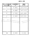
次に演算部6の構成と設定設定について、図3乃至図5を参照して説明する。図3は、
演算部6の構成を、図4は、後述する演算部6の補正テーブル6a1、6b1の例を、ま
た、図5は演算部6の動作を説明する図である。図3において、演算部6は、多チャンネ
ル検出器22a、32aの各チャンネルの検出感度を均一にするための感度補正回路6a
、6bと、補正された検出信号から欠陥信号を抽出する演算回路6cとから構成される。
Next, the configuration and setting of the calculation unit 6 will be described with reference to FIGS. FIG.
FIG. 4 is a diagram illustrating an example of correction tables 6a1 and 6b1 of the calculation unit 6 to be described later, and FIG. 5 is a diagram illustrating the operation of the calculation unit 6. In FIG. 3, a calculation unit 6 is a sensitivity correction circuit 6a for making the detection sensitivity of each channel of the
6b and an arithmetic circuit 6c for extracting a defect signal from the corrected detection signal.
感度補正回路6a(6b)は、放射線源21a、21b(31a、31b)からの透過放
射線のエネルギー強度分布を補正するもので、図5(c)に示す放射線源21a、21b
(31a、31b)らファンビームのエネルギー強度分布は、通常、図5(d)に示す様に
、ガウス分布形状の山形になっているので、図5(f)に示す様に、このエネルギー強度
分布と逆関数のゲイン特性値を有する補正値を補正テーブル6a、6b1に格納して備え
ておく。
The sensitivity correction circuit 6a (6b) corrects the energy intensity distribution of the transmitted radiation from the
(31a, 31b) et al., The energy intensity distribution of the fan beam is normally a mountain shape with a Gaussian distribution shape as shown in FIG. 5 (d), so that this energy intensity is shown in FIG. 5 (f). Correction values having gain characteristic values of distribution and inverse function are stored in the correction tables 6a and 6b1.
この補正値は、被測定材1の品質基準を示す基準材を検出部2(3)の測定位置に置い
て測定し、補正値を補正テーブルとして予め作成する。この補正テーブルは厚さや材質な
どの異なる製品の種類分の基準材で作成しておく。
This correction value is measured by placing a reference material indicating the quality standard of the
図4は、その例を示すもので、多チャンネル検出器22a(32a)からの各チャンネ
ルのAD変換回路25(35)の出力Voを測定し、その逆関数値に定数kを乗じて補正
値として感度テーブルに基準材1の品種毎に予め測定しておく。したがって感度補正され
た感度補正回路6aと感度補正回路6bとの出力の差は、基準材においては同じ出力を示
すので、差は生じないことになる。
FIG. 4 shows such an example. The output Vo of the AD conversion circuit 25 (35) of each channel from the
次に、このように構成、設定された欠陥検出装置の動作について、再び図5及び図6を
参照して説明する。図5(a)は、被測定材1で、同図(b)の断面図に示すように、両
端部の一方に表面に凹凸をもつ表面疵ds、他方に内部欠陥diが発生している場合を図
示したものである。
Next, the operation of the defect detection apparatus configured and set in this way will be described with reference to FIGS. 5 and 6 again. FIG. 5 (a) shows the
夫々の表面疵ds、内部欠陥diは、同図(c)に示す放射線源21a、21bから、
同図(d)に示すようなガウス分布形状のエネルギー強度分布の放射線を照射され、被測
定材1を透過した放射線が同図(e)に示すような直線上に並べられたアレイ状の多チャ
ンネル検出器22a、22bで検出される。
Respective surface defects ds and internal defects di are obtained from the
As shown in FIG. 4D, a radiation having an energy intensity distribution having a Gaussian distribution shape and irradiated through the
このとき、表面疵dsは、多チャンネル検出器22aのチャンネルアドレスnで検出さ
れ、内部欠陥diは多チャンネル検出器32aのチャンネルアドレスmでの位置に存在し
ているとする。
At this time, the surface defect ds is detected by the channel address n of the
多チャンネル検出器22a、32aからの検出信号は、感度補正回路6aでは、基準材
で測定した補正テーブル6a1の同図(f)に示す補正値でゲイン補正され、同図(g)
に示すような均一波高値の信号に補正される。
The detection signals from the
The signal is corrected to a signal having a uniform peak value as shown in FIG.
そして、被測定材1が下流に移動し、表面疵ds、内部欠陥diは検出部3の測定位置
に来ると、夫々多チャンネル検出器32a、32bで検出される。多チャンネル検出器の
32a、32bからの検出信号は検出部2と同様に、感度補正回路6bにおいて、補正テ
ーブル6b1の補正値で補正され、同図hに示すような波高値が均一の出力となる。
When the material to be measured 1 moves downstream and the surface defect ds and the internal defect di come to the measurement position of the
このとき、表面疵dsは材質の変化でなく凹凸の形状変化であるため、検出器22aと
検出器32aからの信号は同一の値を示す。ところが、基準材の材質と異なる介在物等の
内部欠陥di部からの信号は、照射されたエネルギースペクトルが異なるため吸収率特性
が異なり、多チャンネル検出器22bチャンネルmと多チャンネル検出器32bチャンネ
ルmの出力は異なる値となる。
At this time, since the surface wrinkle ds is not a change in material but a change in the shape of the unevenness, the signals from the
そのため、演算回路6cでは、トラッキング回路5で位置補正された感度補正回路6a
の出力と感度補正回路の6bの差の演算出力は、同図iに示すように、内部欠陥di部の
みが差として検出され、表面疵ds部は検出信号レベルが同一であるため差が検出されな
い。
Therefore, in the arithmetic circuit 6c, the sensitivity correction circuit 6a whose position is corrected by the
As shown in FIG. 4i, the calculation output of the difference between the output of 6 and the
このようにして、感度補正された検出信号は、欠陥識別回路7において、演算部6で検
出された夫々の感度補正回路6a、6bで補正された欠陥部の信号、及び感度補正回路6
aと感度補正回路6bとの差から検出された欠陥部の信号とを予め設定される夫々の欠陥
信号の判定値と比較して欠陥を抽出し、抽出された欠陥信号の発生パターンを論理判定し
て表面疵か内部欠陥かを欠陥判定部7で識別判定する。
In this way, the sensitivity-corrected detection signals are detected in the
A defect is extracted by comparing the signal of the defective portion detected from the difference between a and the
この識別判定ロジックは、例えば、検出部1と検出部2いずれか、または双方で欠陥信
号が検出され、検出部1と検出部2の差演算の出力から欠陥信号が検出されないときは表
面疵と判定し、差演算の出力から欠陥信号が検出されたときは、内部欠陥と判定する。
For example, when the defect signal is detected by one or both of the
以上述べた様に、本実施例1によれば、エネルギースペクトルの異なる検出部1、2か
らの検出信号を、基準材で校正した補正テーブルの補正値で補正演算し、その演算出力の
差を予め設定される内部欠陥の判定値と比較判定して内部欠陥の有無を判定し、検出部1
及び検出部2から欠陥信号が検出され、このとき内部欠陥が検出なければ、表面疵と識別
判定するようにしたので、表面疵と内部欠陥の検出を識別でき、且つ誤検出の恐れが少な
い薄鋼板の欠陥検出装置の提供が可能となる。
As described above, according to the first embodiment, the detection signals from the
In addition, if a defect signal is detected from the
本発明は、上述したような各実施例に何ら限定されるものではなく、異なるエネルギー
スペクトルを選択使用することによって、被測定材が非金属場合においても、予め基準材
とする材質で補正テーブルを作成しておくことによって、非金属の表面疵と内部欠陥を同
時に識別処理して検出することが可能な欠陥検出装置を提供することができる。
The present invention is not limited to each of the embodiments described above. By selecting and using different energy spectra, the correction table is made of a reference material in advance even when the material to be measured is non-metallic. By preparing it, it is possible to provide a defect detection apparatus capable of simultaneously identifying and detecting non-metallic surface defects and internal defects.
1 被測定材
2、3 検出部
4 速度検出器
5 トラッキング回路
6 演算部
6a、6b 感度補正回路
6a1、6b1 補正テーブル
6c 演算回路
7 欠陥識別回路
21a、21b 放射線源
31a、31b 放射線源
22a、22b 多チャンネル検出器
32a、32b 多チャンネル検出器
DESCRIPTION OF
Claims (6)
異なるエネルギースペクトルを有する放射線源と多チャンネル検出器とを被測定材を挟み込むように対向配置して、前記被測定材幅方向の透過線量の変化を検出する多チャンネル検出器を有する検出手段を前記被測定材の移動方向で所定の間隔を置いて平行に並置した第1及び第2の検出手段と、
前記被測定材の移動方向の上流に置かれる前記第1の検出手段の出力信号を前記第2の検出手段の出力信号の検出位置まで遅延するトラッキング処理手段と、
前記第1の検出手段の出力信号と前記第2の検出手段の出力信号との差を求める演算手段と、
前記第1及び前記第2の検出手段の出力信号を予め設定される第1の疵判定値と比較して欠陥信号の有無を判定し、前記演算手段の出力信号を予め設定される第2の判定値と比較して欠陥信号の有無を判定して、これらの欠陥信号の発生パターンから欠陥の存在が前記内部欠陥か前記表面疵かを識別する欠陥識別手段とを備え、
前記被測定材に発生する表面疵と内部欠陥とを識別検出するようにしたことを特徴とする欠陥検出装置。 It is a defect detection device for identifying a material to be measured as a thin steel material, and distinguishing surface defects generated on the surface of the thin steel material and internal defects due to inclusions generated inside the thin steel material,
A radiation source and a multichannel detector having a different energy spectra to face arranged to hold the measured material, the said detection means with a multi-channel detector for detecting a change in the transmitted dose of the measured material width direction First and second detection means juxtaposed in parallel at a predetermined interval in the moving direction of the material to be measured;
Tracking processing means for delaying the output signal of the first detection means placed upstream in the moving direction of the material to be measured to the detection position of the output signal of the second detection means;
Arithmetic means for obtaining a difference between an output signal of the first detection means and an output signal of the second detection means;
The output signals of the first and second detection means are compared with a preset first wrinkle determination value to determine the presence or absence of a defect signal, and the output signal of the calculation means is set to a second preset value. to determine the presence or absence of the comparison to the defect signal and the decision value, presence of defects from the generation pattern of these defects signals a defect identification means for identifying whether said internal defect or the surface defects,
A defect detection apparatus characterized by discriminating and detecting surface defects and internal defects generated in the material to be measured.
を特徴とする請求項1に記載の欠陥検出装置。 The defect detection apparatus according to claim 1, wherein each of the radiation sources is configured by a braking X-ray having a different energy spectrum.
Priority Applications (1)
| Application Number | Priority Date | Filing Date | Title |
|---|---|---|---|
| JP2004068607A JP4215664B2 (en) | 2004-03-11 | 2004-03-11 | Defect detection device |
Applications Claiming Priority (1)
| Application Number | Priority Date | Filing Date | Title |
|---|---|---|---|
| JP2004068607A JP4215664B2 (en) | 2004-03-11 | 2004-03-11 | Defect detection device |
Publications (2)
| Publication Number | Publication Date |
|---|---|
| JP2005257423A JP2005257423A (en) | 2005-09-22 |
| JP4215664B2 true JP4215664B2 (en) | 2009-01-28 |
Family
ID=35083290
Family Applications (1)
| Application Number | Title | Priority Date | Filing Date |
|---|---|---|---|
| JP2004068607A Expired - Fee Related JP4215664B2 (en) | 2004-03-11 | 2004-03-11 | Defect detection device |
Country Status (1)
| Country | Link |
|---|---|
| JP (1) | JP4215664B2 (en) |
Families Citing this family (2)
| Publication number | Priority date | Publication date | Assignee | Title |
|---|---|---|---|---|
| JP2007199058A (en) * | 2005-12-28 | 2007-08-09 | Sapporo Breweries Ltd | X-ray inspection apparatus |
| CN114167507B (en) * | 2020-09-11 | 2023-07-11 | 同方威视技术股份有限公司 | Multi-channel static CT device |
Family Cites Families (9)
| Publication number | Priority date | Publication date | Assignee | Title |
|---|---|---|---|---|
| JPS58127153A (en) * | 1982-01-26 | 1983-07-28 | Toshiba Corp | X-ray fluoroscopic inspecting device |
| JPS6110749A (en) * | 1984-06-25 | 1986-01-18 | Kawasaki Steel Corp | Apparatus for measuring surface and internal characteristics of running plate material |
| JPH0692944B2 (en) * | 1986-07-30 | 1994-11-16 | 株式会社日立製作所 | X-ray tomography system |
| JP2595352B2 (en) * | 1989-06-06 | 1997-04-02 | 日立プラント建設株式会社 | Foreign body inspection device during shelling |
| US5089776A (en) * | 1989-09-25 | 1992-02-18 | Nkk Corporation | Apparatus for detecting defects in a moving steel strip with a magnetizing yoke and a sensor placed on opposite sides of the strip |
| JPH0623648B2 (en) * | 1990-07-10 | 1994-03-30 | 新日本製鐵株式会社 | X-ray fluoroscopy inspection method |
| JPH0743321A (en) * | 1993-07-29 | 1995-02-14 | Ishikawajima Harima Heavy Ind Co Ltd | X-ray inspection device |
| JPH11316197A (en) * | 1998-05-06 | 1999-11-16 | Matsushita Electric Works Ltd | Method and device for internal inspection of flat plate material |
| JP2002168803A (en) * | 2000-11-30 | 2002-06-14 | Anritsu Corp | X-ray foreign matter detector |
-
2004
- 2004-03-11 JP JP2004068607A patent/JP4215664B2/en not_active Expired - Fee Related
Also Published As
| Publication number | Publication date |
|---|---|
| JP2005257423A (en) | 2005-09-22 |
Similar Documents
| Publication | Publication Date | Title |
|---|---|---|
| KR900008385B1 (en) | Method and apparatus for detecting defect in circuit pattern of a mask for x-ray exposure | |
| CN106404811B (en) | X-ray transmission inspection apparatus and X-ray transmission inspection method | |
| WO2014034565A1 (en) | Film thickness measurement device | |
| JPH09224632A (en) | Measurement of density of fiber continuous body in tobacco processing industry and apparatus therefor | |
| JP5709721B2 (en) | Belt conveyor belt inspection equipment | |
| TWI439664B (en) | Radiation thickness meter | |
| JP6783456B2 (en) | X-ray transmission inspection device | |
| US4815116A (en) | Method and apparatus for x-ray analysis of rapidly moving multicomponent materials | |
| JP4215664B2 (en) | Defect detection device | |
| JP5601984B2 (en) | Perforated plate surface inspection method and perforated plate surface inspection device | |
| JP2001056317A (en) | Eddy cufrrent flaw detection method and apparatus | |
| JP2619498B2 (en) | Calibration method for magnetic flaw detector | |
| JP5002367B2 (en) | Optical inspection device, pinhole inspection device, film thickness inspection device, and surface inspection device | |
| JP3192846B2 (en) | Pollutant element concentration analysis method and analyzer | |
| TW202215000A (en) | X-ray analysis apparatus | |
| JPH0628690Y2 (en) | Metal plate defect detector | |
| JPH08322537A (en) | Density measuring instrument for double cigarette continuum manufacturing machine in tobacco manufacture industry | |
| KR20200061639A (en) | Inspection device for material | |
| JP6506629B2 (en) | X-ray receiving apparatus and X-ray inspection apparatus provided with the same | |
| WO2024024296A1 (en) | X-ray inspection device and x-ray inspection method | |
| JP7151733B2 (en) | Surface inspection device, surface inspection method, steel manufacturing method, steel quality control method, and steel manufacturing equipment | |
| JPH04264209A (en) | Method and apparatus for measuring lateral profile of thickness of metal strip, especially, steel strip | |
| JP2006038680A (en) | Method for detecting surface profile of strip | |
| JP2005257422A (en) | Apparatus and method for measuring thickness of composite member | |
| JP2008003060A (en) | Device and method for measuring thickness profile |
Legal Events
| Date | Code | Title | Description |
|---|---|---|---|
| RD04 | Notification of resignation of power of attorney |
Free format text: JAPANESE INTERMEDIATE CODE: A7424 Effective date: 20050606 |
|
| A621 | Written request for application examination |
Free format text: JAPANESE INTERMEDIATE CODE: A621 Effective date: 20060216 |
|
| A977 | Report on retrieval |
Free format text: JAPANESE INTERMEDIATE CODE: A971007 Effective date: 20080401 |
|
| A131 | Notification of reasons for refusal |
Free format text: JAPANESE INTERMEDIATE CODE: A131 Effective date: 20080516 |
|
| A521 | Written amendment |
Free format text: JAPANESE INTERMEDIATE CODE: A523 Effective date: 20080620 |
|
| TRDD | Decision of grant or rejection written | ||
| A01 | Written decision to grant a patent or to grant a registration (utility model) |
Free format text: JAPANESE INTERMEDIATE CODE: A01 Effective date: 20081031 |
|
| A01 | Written decision to grant a patent or to grant a registration (utility model) |
Free format text: JAPANESE INTERMEDIATE CODE: A01 |
|
| A61 | First payment of annual fees (during grant procedure) |
Free format text: JAPANESE INTERMEDIATE CODE: A61 Effective date: 20081104 |
|
| FPAY | Renewal fee payment (event date is renewal date of database) |
Free format text: PAYMENT UNTIL: 20111114 Year of fee payment: 3 |
|
| FPAY | Renewal fee payment (event date is renewal date of database) |
Free format text: PAYMENT UNTIL: 20121114 Year of fee payment: 4 |
|
| FPAY | Renewal fee payment (event date is renewal date of database) |
Free format text: PAYMENT UNTIL: 20131114 Year of fee payment: 5 |
|
| LAPS | Cancellation because of no payment of annual fees |