JP4215517B2 - 燃料噴射システム - Google Patents
燃料噴射システム Download PDFInfo
- Publication number
- JP4215517B2 JP4215517B2 JP2002587800A JP2002587800A JP4215517B2 JP 4215517 B2 JP4215517 B2 JP 4215517B2 JP 2002587800 A JP2002587800 A JP 2002587800A JP 2002587800 A JP2002587800 A JP 2002587800A JP 4215517 B2 JP4215517 B2 JP 4215517B2
- Authority
- JP
- Japan
- Prior art keywords
- fuel injection
- opening angle
- injection system
- jet
- internal combustion
- Prior art date
- Legal status (The legal status is an assumption and is not a legal conclusion. Google has not performed a legal analysis and makes no representation as to the accuracy of the status listed.)
- Expired - Fee Related
Links
Images


Classifications
-
- F—MECHANICAL ENGINEERING; LIGHTING; HEATING; WEAPONS; BLASTING
- F02—COMBUSTION ENGINES; HOT-GAS OR COMBUSTION-PRODUCT ENGINE PLANTS
- F02M—SUPPLYING COMBUSTION ENGINES IN GENERAL WITH COMBUSTIBLE MIXTURES OR CONSTITUENTS THEREOF
- F02M69/00—Low-pressure fuel-injection apparatus ; Apparatus with both continuous and intermittent injection; Apparatus injecting different types of fuel
- F02M69/04—Injectors peculiar thereto
- F02M69/042—Positioning of injectors with respect to engine, e.g. in the air intake conduit
- F02M69/045—Positioning of injectors with respect to engine, e.g. in the air intake conduit for injecting into the combustion chamber
-
- F—MECHANICAL ENGINEERING; LIGHTING; HEATING; WEAPONS; BLASTING
- F02—COMBUSTION ENGINES; HOT-GAS OR COMBUSTION-PRODUCT ENGINE PLANTS
- F02M—SUPPLYING COMBUSTION ENGINES IN GENERAL WITH COMBUSTIBLE MIXTURES OR CONSTITUENTS THEREOF
- F02M61/00—Fuel-injectors not provided for in groups F02M39/00 - F02M57/00 or F02M67/00
- F02M61/16—Details not provided for in, or of interest apart from, the apparatus of groups F02M61/02 - F02M61/14
- F02M61/18—Injection nozzles, e.g. having valve seats; Details of valve member seated ends, not otherwise provided for
-
- F—MECHANICAL ENGINEERING; LIGHTING; HEATING; WEAPONS; BLASTING
- F02—COMBUSTION ENGINES; HOT-GAS OR COMBUSTION-PRODUCT ENGINE PLANTS
- F02B—INTERNAL-COMBUSTION PISTON ENGINES; COMBUSTION ENGINES IN GENERAL
- F02B23/00—Other engines characterised by special shape or construction of combustion chambers to improve operation
- F02B23/08—Other engines characterised by special shape or construction of combustion chambers to improve operation with positive ignition
- F02B23/10—Other engines characterised by special shape or construction of combustion chambers to improve operation with positive ignition with separate admission of air and fuel into cylinder
- F02B23/101—Other engines characterised by special shape or construction of combustion chambers to improve operation with positive ignition with separate admission of air and fuel into cylinder the injector being placed on or close to the cylinder centre axis, e.g. with mixture formation using spray guided concepts
-
- F—MECHANICAL ENGINEERING; LIGHTING; HEATING; WEAPONS; BLASTING
- F02—COMBUSTION ENGINES; HOT-GAS OR COMBUSTION-PRODUCT ENGINE PLANTS
- F02M—SUPPLYING COMBUSTION ENGINES IN GENERAL WITH COMBUSTIBLE MIXTURES OR CONSTITUENTS THEREOF
- F02M61/00—Fuel-injectors not provided for in groups F02M39/00 - F02M57/00 or F02M67/00
- F02M61/16—Details not provided for in, or of interest apart from, the apparatus of groups F02M61/02 - F02M61/14
- F02M61/18—Injection nozzles, e.g. having valve seats; Details of valve member seated ends, not otherwise provided for
- F02M61/1806—Injection nozzles, e.g. having valve seats; Details of valve member seated ends, not otherwise provided for characterised by the arrangement of discharge orifices, e.g. orientation or size
-
- F—MECHANICAL ENGINEERING; LIGHTING; HEATING; WEAPONS; BLASTING
- F02—COMBUSTION ENGINES; HOT-GAS OR COMBUSTION-PRODUCT ENGINE PLANTS
- F02B—INTERNAL-COMBUSTION PISTON ENGINES; COMBUSTION ENGINES IN GENERAL
- F02B23/00—Other engines characterised by special shape or construction of combustion chambers to improve operation
- F02B23/08—Other engines characterised by special shape or construction of combustion chambers to improve operation with positive ignition
- F02B23/10—Other engines characterised by special shape or construction of combustion chambers to improve operation with positive ignition with separate admission of air and fuel into cylinder
- F02B2023/103—Other engines characterised by special shape or construction of combustion chambers to improve operation with positive ignition with separate admission of air and fuel into cylinder the injector having a multi-hole nozzle for generating multiple sprays
-
- F—MECHANICAL ENGINEERING; LIGHTING; HEATING; WEAPONS; BLASTING
- F02—COMBUSTION ENGINES; HOT-GAS OR COMBUSTION-PRODUCT ENGINE PLANTS
- F02B—INTERNAL-COMBUSTION PISTON ENGINES; COMBUSTION ENGINES IN GENERAL
- F02B75/00—Other engines
- F02B75/12—Other methods of operation
- F02B2075/125—Direct injection in the combustion chamber for spark ignition engines, i.e. not in pre-combustion chamber
-
- F—MECHANICAL ENGINEERING; LIGHTING; HEATING; WEAPONS; BLASTING
- F02—COMBUSTION ENGINES; HOT-GAS OR COMBUSTION-PRODUCT ENGINE PLANTS
- F02F—CYLINDERS, PISTONS OR CASINGS, FOR COMBUSTION ENGINES; ARRANGEMENTS OF SEALINGS IN COMBUSTION ENGINES
- F02F3/00—Pistons
- F02F3/26—Pistons having combustion chamber in piston head
-
- Y—GENERAL TAGGING OF NEW TECHNOLOGICAL DEVELOPMENTS; GENERAL TAGGING OF CROSS-SECTIONAL TECHNOLOGIES SPANNING OVER SEVERAL SECTIONS OF THE IPC; TECHNICAL SUBJECTS COVERED BY FORMER USPC CROSS-REFERENCE ART COLLECTIONS [XRACs] AND DIGESTS
- Y02—TECHNOLOGIES OR APPLICATIONS FOR MITIGATION OR ADAPTATION AGAINST CLIMATE CHANGE
- Y02T—CLIMATE CHANGE MITIGATION TECHNOLOGIES RELATED TO TRANSPORTATION
- Y02T10/00—Road transport of goods or passengers
- Y02T10/10—Internal combustion engine [ICE] based vehicles
- Y02T10/12—Improving ICE efficiencies
Landscapes
- Engineering & Computer Science (AREA)
- Chemical & Material Sciences (AREA)
- Combustion & Propulsion (AREA)
- Mechanical Engineering (AREA)
- General Engineering & Computer Science (AREA)
- Fuel-Injection Apparatus (AREA)
- Combustion Methods Of Internal-Combustion Engines (AREA)
Description
背景技術
本発明は主請求項の上位概念に記載した形式の燃料噴射システムから出発している。
【0002】
内部で混合気形成を行う混合気圧縮外部点火式内燃機関では、成層燃焼運転のために点火プラグ領域内には着火可能範囲内の所定の燃料/空気比を有する“混合気噴霧(雲)”が必要である。この目的のために、内向きまたは外向きに開き、かつコーンスプレーを生じるノズルを備えた燃料噴射弁が使用される。
【0003】
例えばドイツ連邦共和国特許公開第19804463号明細書からは、ピストンシリンダ装置によって形成された燃焼室内へ燃料を噴射する少なくとも1つの燃料噴射弁と、燃焼室内へ突入した点火プラグとを備えた、混合気圧縮外部点火式内燃機関のための燃料噴射システムが公知である。その場合、燃料噴射弁のノズルボディは該ノズルボディの周囲にわたり分配されて配置された少なくとも1列の噴口を備えている。噴口を介した狙を付けた燃料噴射により、噴流案内式燃焼法が混合気噴霧の形成によって実現され、その際、少なくとも1つの噴流が点火プラグまたはそれの極めて近い周囲へ向けられる。その他の噴流は少なくともほぼ閉じられた、もしくは関連する混合気噴霧の形成のために役立てられる。
【0004】
ドイツ連邦共和国特許公開第19804463号明細書から公知のこの燃料噴射システムの欠点とするところは特に、供用されている燃焼室が不完全にしか利用されず、このことにより、高すぎる空気成分による低価値の混合気形成と、続く個々のミスファイヤに起因する不燃焼炭化水素の過剰な放出と、高い燃費とが結果として生じることにある。
【0005】
発明の利点
これに対して、主請求項の特徴概念に記載の特徴を備えた本発明による燃料噴射システムが有する利点は、燃焼室内へ噴射された混合気噴霧の広がりが内燃機関の縦方向と横方向とで互いに異なることにより、かつこのことに起因して生じる混合気噴霧の楕円形横断面によって、燃焼室への混合気噴霧のより良い適合、ひいては効果的な燃焼と、比較的低い燃費と、わずかな有害物質放出が得られることにある。
【0006】
従属請求項に記載した手段によれば、主請求項に記載した燃料噴射システムの有利な実施形が可能である。
【0007】
特に、噴射噴流が直に点火プラグへ方向付けされていないため、点火プラグ位置に関連した接線方向の燃料噴射によって点火プラグの熱衝撃負荷と煤付着とが軽減されるのが有利である。有利には、噴口の狙いを付けた配置ひいては燃焼室内の噴射噴流の狙いを付けた配置によって、シリンダヘッド内の吸込弁および排出弁ならびに点火プラグの組込み位置も考慮されることができ、それにもかかわらず、燃焼室のジオメトリが最適に利用される。
【0008】
本燃料噴射システムのために適した燃料噴射弁は有利にも付加的な製作費用なしにコスト安に製作されることができる。
【0009】
次に、本発明の1実施例を図面に簡略に示し、以下の記載で詳細に説明する。
【0010】
実施例の説明
図1は本発明による燃料噴射システム2を備えた内燃機関1の1実施例を抜粋的な断面図示で示す。
【0011】
燃料噴射システム2はシリンダ壁13を備えたシリンダブロックを有しており、該シリンダ壁13内にはピストン6が案内されている。ピストン6は連接棒14によってシリンダ壁13に沿って上下に案内される。シリンダ壁13は端面側でシリンダヘッド3によって閉鎖されている。シリンダ壁13と、ピストン6とシリンダヘッド3とが燃焼室7を閉じている。
【0012】
シリンダヘッド3内には燃料噴射弁5が有利には中央に配置されている。その場所から若干側方へずれたところに点火プラグ4がシリンダヘッド3の孔内に挿入されている。さらに、少なくとも1つの吸込弁11と、少なくとも1つの排出弁12とが設けられている。
【0013】
運転中の燃料噴射システム2は燃料噴射弁5内に存在する噴口を通して、全体として1つの円錐状の燃料噴流を形成する複数の噴射噴流を燃焼室7内へ噴射する。燃焼室7内では燃料と空気との混合により混合気噴霧9が形成される。該混合気噴霧9は点火プラグ8によって点火される。本発明による円錐状の燃料噴流の形状を図2および図3で詳細に説明する。
【0014】
図1から分かるように、内燃機関1の燃焼室7は屋根形燃焼室の形状でシリンダヘッド3内に形成されており、該屋根形燃焼室は屋根傾斜部15と屋根棟16とを有している。屋根棟16には燃料噴射弁5が配置されており、他面において屋根傾斜部15にはガス交換弁11,12が配置されている。このことは特に2つ以上のガス交換弁11,12が使用される場合には有利である。それというのは、このことにより内燃機関1の全負荷時にガス交換弁に空気が良好に供給されるからである。
【0015】
燃焼室7を最適に利用することができるように、かつ吸込弁11および排出弁12の位置を考慮することができるように、本発明によれば燃料噴射弁5は、燃料噴射弁5によって燃焼室7内へ噴射される噴射噴流10が内燃機関1の横方向でよりも内燃機関の縦方向で大きな角度で噴射されるように形成されている。
【0016】
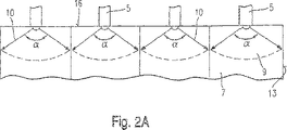
図2Aには前述の手段を明らかにするために、4つのシリンダを備えた1実施例の内燃機関1の極めて概略的な縦断面が示されており、他面において図2Bは内燃機関1の横方向で1つのシリンダを断面した図を示す。
【0017】
図2Aから分かるように、噴射噴流10は燃料噴射弁5によって最大の開角αで噴射される。この開角は燃料噴射弁5の噴口の位置により規定されている。
【0018】
内燃機関1の横方向では図2Bに示されているように、燃焼室7を制限している屋根傾斜部15に基づき、角度αより小さな角度βで噴射噴流10が噴射される。それゆえ、ガス交換弁11,12ならびに図2Bには図示されていない点火プラグ4は噴射噴流10によってたんに接線方向でのみ擦過され、直には噴射を受けない。このことは特に点火プラグ4では有利である。それというのは、この形式で電極の熱衝撃負荷ならびに炭化が軽減され、かつ点火プラグ4の寿命が延びることができるからである。
【0019】
噴射された混合気噴霧9の横断面は、2つの互いに直交する空間方向の開角αと開角βとの大きさが異なることに起因して楕円形である。混合気噴霧9の側方の偏平により、混合気噴霧は最適に燃焼室7の形状に適合する。
【0020】
最大の開角αと最小の開角βとの間に位置する噴射角は任意に多数の個々の噴射噴流10の使用により連続的に極大値に近づけられることができる。図3には例示的に10個の噴射噴流10から成る混合気噴霧9が示されている。この場合、最大の開角αを有する噴射噴流は存在せず、むしろ互いに並んで位置する2つの噴射噴流10が最大の開角αに近づけられている。このような配置は、熱衝撃負荷の回避のために直に噴射を受けないほうがよい例えば屋根棟内で側方に配置された2つの点火プラグ4が設けられている場合に有利である。
【0021】
点火プラグ4が例えば“屋根傾斜部”内に位置する場合には、最小の開角βを有する噴射噴流は避けられ、むしろ同様に互いに並んで位置する2つの噴射噴流が最小の開角βに近づけられる。
【0022】
燃料噴射弁5の任意に多数の噴口を使用することにより、噴射噴流10の任意の配置を生じることができる。個々の噴射噴流10の相互の噴流隔たり角度γは同じであってもよく、または異なっていてもよい。その場合、噴流隔たり角度γの設計は混合気噴霧9の開角αと開角βとの設計とは無関係である。
【0023】
本発明は図示の実施例に制限されず、かつ例えば多かれ少なかれ複数の噴射噴流10と、ガス交換弁11,12と、特に複数の点火プラグ4と、可変の行程室容積とを有する燃料噴射システムのためにも使用可能である。
【図面の簡単な説明】
【図1】 本発明により形成された燃料噴射システムを備えた内燃機関の1実施例を図式的に断面した図である。
【図2A】 内燃機関と本発明による燃料噴射システムとを縦方向に図式的に断面した図である。
【図2B】 内燃機関と本発明による燃料噴射システムとを横方向に図式的に断面した図である。
【図3】 内燃機関の燃焼室内に生じた混合気噴霧を図式的に示した図である。
Claims (5)
- 内燃機関(1)のための燃料噴射システム(2)であって、シリンダ壁(13)によって制限された燃焼室(7)内へ燃料を噴射する少なくとも1つの燃料噴射弁(5)が設けられており、シリンダ壁(13)内にピストン(6)が案内されており、燃焼室(7)内へ突入した点火プラグが設けられており、燃料噴射弁(5)が複数の噴射噴流(10)を燃焼室(7)内へ噴射するようになっており、複数の噴射噴流(10)が、楕円形横断面を有する円錐状の1つの混合気噴霧(9)を燃焼室(7)内に発生させ、該混合気噴霧(9)の楕円形横断面が、内燃機関(1)の縦方向に開角αを有し、かつ内燃機関(1)の横方向に開角βを有しており、内燃機関(1)の縦方向の開角αが、内燃機関(1)の横方向の開角βよりも大きく、燃料噴射弁(5)がシリンダヘッド(2)の屋根傾斜部(15)によって制限された棟(16)に配置されている形式のものにおいて、
開角αおよび開角βで噴射される噴射噴流(10)の間に位置する噴射噴流(10)が開角αおよび開角βに連続的に近づいていることを特徴とする燃料噴射システム。 - 最小の開角βが屋根傾斜部(15)に沿って方向付けされていることを特徴とする請求項1記載の燃料噴射システム。
- 個々の噴射噴流(10)の間の噴流隔たり角度γが同じ大きさであることを特徴とする請求項1又は2記載の燃料噴射システム。
- 個々の噴射噴流(10)の間の噴流隔たり角度γが種々異なっていることを特徴とする請求項1から3までのいずれか1項記載の燃料噴射システム。
- シリンダヘッド(2)内に配置されたガス交換弁(11,12)と点火プラグ(4)とに対して噴射噴流(10)が接線方向に向くように、噴射噴流(10)が方向付けされていることを特徴とする請求項1から4までのいずれか1項記載の燃料噴射システム。
Applications Claiming Priority (2)
| Application Number | Priority Date | Filing Date | Title |
|---|---|---|---|
| DE10122352A DE10122352B4 (de) | 2001-05-09 | 2001-05-09 | Brennstoffeinspritzsystem |
| PCT/DE2002/001660 WO2002090763A1 (de) | 2001-05-09 | 2002-05-08 | Brennstoffeinspritzsystem |
Publications (2)
| Publication Number | Publication Date |
|---|---|
| JP2004519606A JP2004519606A (ja) | 2004-07-02 |
| JP4215517B2 true JP4215517B2 (ja) | 2009-01-28 |
Family
ID=7684047
Family Applications (1)
| Application Number | Title | Priority Date | Filing Date |
|---|---|---|---|
| JP2002587800A Expired - Fee Related JP4215517B2 (ja) | 2001-05-09 | 2002-05-08 | 燃料噴射システム |
Country Status (6)
| Country | Link |
|---|---|
| US (1) | US6877477B2 (ja) |
| EP (1) | EP1387952B1 (ja) |
| JP (1) | JP4215517B2 (ja) |
| KR (1) | KR100853639B1 (ja) |
| DE (2) | DE10122352B4 (ja) |
| WO (1) | WO2002090763A1 (ja) |
Families Citing this family (8)
| Publication number | Priority date | Publication date | Assignee | Title |
|---|---|---|---|---|
| US9279193B2 (en) | 2002-12-27 | 2016-03-08 | Momentive Performance Materials Inc. | Method of making a gallium nitride crystalline composition having a low dislocation density |
| US8357945B2 (en) | 2002-12-27 | 2013-01-22 | Momentive Performance Materials Inc. | Gallium nitride crystal and method of making same |
| DE10331267A1 (de) * | 2003-07-10 | 2005-02-03 | Robert Bosch Gmbh | Brennstoffeinspritzsystem |
| DE102004005727A1 (de) | 2004-02-05 | 2005-09-01 | Robert Bosch Gmbh | Brennstoffeinspritzsystem |
| US7360143B2 (en) * | 2005-05-24 | 2008-04-15 | International Business Machines Corporation | Redundant storage of computer data |
| ITBO20060703A1 (it) * | 2006-10-12 | 2008-04-13 | Ferrari Spa | Motore a combustione interna ad alte prestazioni con iniezione diretta del carburante |
| JP6235400B2 (ja) * | 2014-04-04 | 2017-11-22 | 株式会社Soken | 燃料噴射弁 |
| JP6044603B2 (ja) * | 2014-07-23 | 2016-12-14 | トヨタ自動車株式会社 | 内燃機関の制御装置 |
Family Cites Families (13)
| Publication number | Priority date | Publication date | Assignee | Title |
|---|---|---|---|---|
| JP3498882B2 (ja) | 1996-06-24 | 2004-02-23 | 日産自動車株式会社 | 筒内直噴式内燃機関 |
| DE19642653C5 (de) | 1996-10-16 | 2008-02-21 | Daimler Ag | Verfahren zur Bildung eines zündfähigen Kraftstoff/Luft-Gemisches |
| KR19990042831A (ko) * | 1997-11-28 | 1999-06-15 | 정몽규 | 텀블용 직접 분사 엔진 |
| DE19804463B4 (de) | 1998-02-05 | 2006-06-14 | Daimlerchrysler Ag | Kraftstoffeinspritzsystem für Ottomotoren |
| JP2000104647A (ja) | 1998-09-25 | 2000-04-11 | Denso Corp | 燃料噴射ノズル |
| JP2001027170A (ja) * | 1999-07-12 | 2001-01-30 | Nissan Motor Co Ltd | 筒内直噴式ガソリンエンジン及び燃料噴射弁 |
| JP3651338B2 (ja) * | 1999-12-15 | 2005-05-25 | 株式会社日立製作所 | 筒内燃料噴射弁およびこれを搭載した内燃機関 |
| DE10026324A1 (de) * | 2000-05-26 | 2001-11-29 | Bosch Gmbh Robert | Brennstoffeinspritzsystem |
| DE10026321A1 (de) | 2000-05-26 | 2001-11-29 | Bosch Gmbh Robert | Brennstoffeinspritzsystem und Verfahren zum Einspritzen |
| US6510836B2 (en) * | 2000-07-03 | 2003-01-28 | Murad M. Ismailov | Swirl injector for internal combustion engine |
| JP3997781B2 (ja) * | 2002-01-09 | 2007-10-24 | 日産自動車株式会社 | 筒内直噴エンジン |
| US6588396B1 (en) * | 2002-02-01 | 2003-07-08 | General Motors Corporation | Spark ignition direct injection engine with oval fuel spray into oblong piston bowl |
| JP4054223B2 (ja) * | 2002-06-12 | 2008-02-27 | 富士重工業株式会社 | 筒内噴射型エンジンおよび筒内噴射型エンジンの制御方法 |
-
2001
- 2001-05-09 DE DE10122352A patent/DE10122352B4/de not_active Expired - Fee Related
-
2002
- 2002-05-08 WO PCT/DE2002/001660 patent/WO2002090763A1/de active IP Right Grant
- 2002-05-08 KR KR1020037000212A patent/KR100853639B1/ko not_active IP Right Cessation
- 2002-05-08 EP EP02742724A patent/EP1387952B1/de not_active Expired - Lifetime
- 2002-05-08 US US10/332,558 patent/US6877477B2/en not_active Expired - Lifetime
- 2002-05-08 DE DE50210240T patent/DE50210240D1/de not_active Expired - Lifetime
- 2002-05-08 JP JP2002587800A patent/JP4215517B2/ja not_active Expired - Fee Related
Also Published As
| Publication number | Publication date |
|---|---|
| DE50210240D1 (de) | 2007-07-12 |
| DE10122352A1 (de) | 2002-11-21 |
| US20040025834A1 (en) | 2004-02-12 |
| JP2004519606A (ja) | 2004-07-02 |
| US6877477B2 (en) | 2005-04-12 |
| DE10122352B4 (de) | 2006-08-03 |
| KR20030014324A (ko) | 2003-02-15 |
| EP1387952B1 (de) | 2007-05-30 |
| EP1387952A1 (de) | 2004-02-11 |
| KR100853639B1 (ko) | 2008-08-25 |
| WO2002090763A1 (de) | 2002-11-14 |
Similar Documents
| Publication | Publication Date | Title |
|---|---|---|
| US5335635A (en) | Combustion chamber for an internal combustion engine | |
| EP1006266B1 (en) | Direct fuel injection-type spark ignition internal combustion engine | |
| US6418905B1 (en) | Internal combustion engine with controlled ignition and direct injection | |
| US6644267B2 (en) | Fuel injection system | |
| US6742493B2 (en) | Fuel injection system and method for injection | |
| JP4047177B2 (ja) | 燃料噴射システム | |
| US6983733B2 (en) | Direct-injection spark-ignition engine | |
| US5357924A (en) | Direct-injection type compression-ignition internal combustion engine | |
| JPH0579331A (ja) | 空気圧縮および弁作動式内燃機関 | |
| EP1026377B1 (en) | Direct-fuel-injection-type spark-ignition internal combustion engine | |
| US6659070B2 (en) | Fuel injection system | |
| US5203298A (en) | Pre-combustion chamber for internal combustion engine | |
| JP4215517B2 (ja) | 燃料噴射システム | |
| JP4662755B2 (ja) | 燃料噴射システム | |
| US6325040B1 (en) | Cylinder direct injection engine | |
| US6267096B1 (en) | Three-valve cylinder head system | |
| JP2002089267A (ja) | ガソリン直噴エンジン | |
| US20070261667A1 (en) | Spark ignition internal combustion engine with direct fuel injection | |
| WO2020196682A1 (ja) | 副室式内燃機関 | |
| JPS6316123A (ja) | 内燃機関 | |
| JP2562423Y2 (ja) | グロープラグ | |
| JP4026406B2 (ja) | 直噴火花点火式内燃機関 | |
| JPS5968518A (ja) | 副室式機関の燃焼室 | |
| KR100203507B1 (ko) | 직분식 가솔린 엔진 | |
| JPH07189700A (ja) | ディーゼルエンジンの直噴式燃焼室装置 |
Legal Events
| Date | Code | Title | Description |
|---|---|---|---|
| A621 | Written request for application examination |
Free format text: JAPANESE INTERMEDIATE CODE: A621 Effective date: 20050506 |
|
| A131 | Notification of reasons for refusal |
Free format text: JAPANESE INTERMEDIATE CODE: A131 Effective date: 20071109 |
|
| A601 | Written request for extension of time |
Free format text: JAPANESE INTERMEDIATE CODE: A601 Effective date: 20080212 |
|
| A602 | Written permission of extension of time |
Free format text: JAPANESE INTERMEDIATE CODE: A602 Effective date: 20080221 |
|
| A521 | Written amendment |
Free format text: JAPANESE INTERMEDIATE CODE: A523 Effective date: 20080307 |
|
| A131 | Notification of reasons for refusal |
Free format text: JAPANESE INTERMEDIATE CODE: A131 Effective date: 20080403 |
|
| A601 | Written request for extension of time |
Free format text: JAPANESE INTERMEDIATE CODE: A601 Effective date: 20080702 |
|
| A602 | Written permission of extension of time |
Free format text: JAPANESE INTERMEDIATE CODE: A602 Effective date: 20080709 |
|
| A601 | Written request for extension of time |
Free format text: JAPANESE INTERMEDIATE CODE: A601 Effective date: 20080731 |
|
| A602 | Written permission of extension of time |
Free format text: JAPANESE INTERMEDIATE CODE: A602 Effective date: 20080807 |
|
| A601 | Written request for extension of time |
Free format text: JAPANESE INTERMEDIATE CODE: A601 Effective date: 20080903 |
|
| A521 | Written amendment |
Free format text: JAPANESE INTERMEDIATE CODE: A523 Effective date: 20080904 |
|
| A602 | Written permission of extension of time |
Free format text: JAPANESE INTERMEDIATE CODE: A602 Effective date: 20080910 |
|
| TRDD | Decision of grant or rejection written | ||
| A01 | Written decision to grant a patent or to grant a registration (utility model) |
Free format text: JAPANESE INTERMEDIATE CODE: A01 Effective date: 20081003 |
|
| A01 | Written decision to grant a patent or to grant a registration (utility model) |
Free format text: JAPANESE INTERMEDIATE CODE: A01 |
|
| A61 | First payment of annual fees (during grant procedure) |
Free format text: JAPANESE INTERMEDIATE CODE: A61 Effective date: 20081104 |
|
| R150 | Certificate of patent or registration of utility model |
Free format text: JAPANESE INTERMEDIATE CODE: R150 |
|
| FPAY | Renewal fee payment (event date is renewal date of database) |
Free format text: PAYMENT UNTIL: 20111114 Year of fee payment: 3 |
|
| FPAY | Renewal fee payment (event date is renewal date of database) |
Free format text: PAYMENT UNTIL: 20121114 Year of fee payment: 4 |
|
| FPAY | Renewal fee payment (event date is renewal date of database) |
Free format text: PAYMENT UNTIL: 20131114 Year of fee payment: 5 |
|
| R250 | Receipt of annual fees |
Free format text: JAPANESE INTERMEDIATE CODE: R250 |
|
| R250 | Receipt of annual fees |
Free format text: JAPANESE INTERMEDIATE CODE: R250 |
|
| R250 | Receipt of annual fees |
Free format text: JAPANESE INTERMEDIATE CODE: R250 |
|
| LAPS | Cancellation because of no payment of annual fees |