JP4215516B2 - How to process information - Google Patents
How to process information Download PDFInfo
- Publication number
- JP4215516B2 JP4215516B2 JP2002580255A JP2002580255A JP4215516B2 JP 4215516 B2 JP4215516 B2 JP 4215516B2 JP 2002580255 A JP2002580255 A JP 2002580255A JP 2002580255 A JP2002580255 A JP 2002580255A JP 4215516 B2 JP4215516 B2 JP 4215516B2
- Authority
- JP
- Japan
- Prior art keywords
- printer
- coding pattern
- information
- algorithm
- section
- Prior art date
- Legal status (The legal status is an assumption and is not a legal conclusion. Google has not performed a legal analysis and makes no representation as to the accuracy of the status listed.)
- Expired - Fee Related
Links
Images


Classifications
-
- G—PHYSICS
- G06—COMPUTING; CALCULATING OR COUNTING
- G06F—ELECTRIC DIGITAL DATA PROCESSING
- G06F3/00—Input arrangements for transferring data to be processed into a form capable of being handled by the computer; Output arrangements for transferring data from processing unit to output unit, e.g. interface arrangements
- G06F3/01—Input arrangements or combined input and output arrangements for interaction between user and computer
- G06F3/03—Arrangements for converting the position or the displacement of a member into a coded form
- G06F3/0304—Detection arrangements using opto-electronic means
- G06F3/0317—Detection arrangements using opto-electronic means in co-operation with a patterned surface, e.g. absolute position or relative movement detection for an optical mouse or pen positioned with respect to a coded surface
- G06F3/0321—Detection arrangements using opto-electronic means in co-operation with a patterned surface, e.g. absolute position or relative movement detection for an optical mouse or pen positioned with respect to a coded surface by optically sensing the absolute position with respect to a regularly patterned surface forming a passive digitiser, e.g. pen optically detecting position indicative tags printed on a paper sheet
Abstract
Description
本発明は、クレーム1の序文にしたがって、コンピュータユニットと、前記コンピュータユニットに接続されたプリンタユニットとを備えるシステム中で、位置コーディングパターンのプリントアウトを発生する方法と;クレーム18の序文にしたがって位置コーディングパターンのプリントアウトを発生するシステムと;クレーム19の序文にしたがったプリンタデバイスと;クレーム23の序文によるコンピュータプログラムと;クレーム24にしたがったディジタルストレージ媒体と;クレーム25によるプリンタと;に関する。 The invention relates to a method for generating a printout of a position-coding pattern in a system comprising a computer unit and a printer unit connected to the computer unit according to the preamble of claim 1; A system for generating a printout of a coding pattern; a printer device according to the preamble of claim 19; a computer program according to the preamble of claim 23; a digital storage medium according to claim 24; and a printer according to claim 25.
本発明は、位置コーディングパターンの発生のために用いられることを意図するものである。位置コーディングパターンとは、ベース上に印刷された多くの記号から成るものである。特定の最小限の数の記号を読み取りデバイスで光学的に記録することによって、パターン中でのこれらの記号の絶対位置を検出し、それにより読み取りデバイスの絶対位置を検出することが可能である。 The present invention is intended to be used for the generation of position coding patterns. A position coding pattern consists of a number of symbols printed on a base. By optically recording a certain minimum number of symbols with a reading device, it is possible to detect the absolute position of these symbols in the pattern , thereby detecting the absolute position of the reading device.
このようなパターンは、さまざまな方法で使用可能である。たとえば、読み取りデバイスは、ベース上に書き込むために用いられるインクペン中に組み込むことが可能である。ベース上にユーザがテキストを書き込んだり、図を描画したりするのと同時に、ベース上でのペンの移動を、位置のシーケンスとして記録することが可能である。このようにして、ユーザがベース上に書いたもののディジタルコピーが、従来のスキャナを用いることなく生成される。 Such a pattern can be used in various ways. For example, the reading device can be incorporated into an ink pen used to write on the base. At the same time that a user writes text or draws a figure on the base, pen movement on the base can be recorded as a sequence of positions. In this way, a digital copy of what the user wrote on the base is generated without using a conventional scanner.
位置コーディングパターンは、複数の方法で設計することが可能である。さまざまなサイズを持つドットという形態で記号を用い、大きいドットが“1”をコーディングし、小さいドットが“0”をコーディングすることができるようにすることが提案されてきた。このようなパターンが、参照してここに組み込むWO 00/73983に記載されている。代替例として、ラスターを基準としてさまざまに変位するドットで、さまざまな記号をコーディングすることが可能である。このようなパターンが、参照してここに組み込むWO 01/16691、PCT/SE00/01895及びPCT/SE00/01897に記載されている。 The position coding pattern can be designed in several ways. It has been proposed to use symbols in the form of dots of various sizes so that large dots can code "1" and small dots can code "0". Such a pattern is described in WO 00/73783, which is incorporated herein by reference. As an alternative, it is possible to code different symbols with dots that are displaced differently with respect to the raster. Such patterns are described in WO 01/16691, PCT / SE00 / 01895 and PCT / SE00 / 01897, which are incorporated herein by reference.
このような位置コーディングパターンは、非常に大きい表面上での固有の位置を良好な解像度でコーディングすることが可能である。460万平方キロメートルを、良好な解像度で固有の位置でコーディングすることが可能であると計算されている。 Such a position coding pattern can code unique positions on a very large surface with good resolution. It has been calculated that 4.6 million square kilometers can be coded at a unique position with good resolution.
多くの場合、位置コーディングパターンを持つベースを、グラフィック業界で、大規模にしかも高精度で生成することが可能である。このことは、たとえば、日記帳やノートパッドの生産にも当てはまることである。しかしながら、位置コーディングパターンを持つベースを小規模で作成することが望ましい場合もある。これは、たとえばインクジェット又はレーザタイプのプリンタが接続されているパソコンを用いれば実行可能である。 In many cases, a base with a position coding pattern can be generated in the graphics industry with large scale and high accuracy. This is also true for the production of diaries and notepads, for example. However, it may be desirable to create a base with a position coding pattern on a small scale. This is, for example, an inkjet or laser type printer can execute by using the personal computer is connected.
これは、位置コーディングパターンの内の必要とされる部分を、図形形式、たとえばbmp(bmp=bitmap)形式でファイルとして作成されるような方法で実行することが可能である。この図形ファイルは、ページを記述するコードであって、通常はプリンタに依存しないコード、たとえば、POSTSCRIPT(商標)に変換され、その後、プリンタユニットに送信される。このページ記述コードに基づいて、プリンタユニットは、プリンタのハードウエアを制御するために用いられる対応する情報を生成する。このハードウエアは、レーザプリンタの場合、関連のオプティックスを持ったレーザダイオードを備える。プリンタがインクジェットプリンタである場合、このハードウエアはインクエジェクタを備える。次に、ベース、たとえば、紙の上でプリントアウトを実行する。 This can be done in such a way that the required part of the position coding pattern is created as a file in a graphic format, for example bmp (bmp = bitmap) format. The graphic file is a code that describes the page, usually independent code printer, for example, be converted into POSTSCRIPT (trademark), then sent to the printer unit. Based on the page description code, the printer unit generates corresponding information used to control the printer hardware. This hardware, in the case of a laser printer, comprises a laser diode with associated optics. If the printer is an ink jet printer, the hardware includes an ink ejector. Next, a printout is performed on the base, eg, paper.
この方法に伴う問題は、結果として得られるプリントアウトに、システムが「ノイズ」と呼ばれ得るなにかを持ち込んでしまうことである。このノイズは、とりわけ、量子化の結果として発生して、位置コーディングパターン中で記号が少し変位及び/又は変形する結果となる。この量子化は、図形ファイルがページ記述コードに作り変えられる際及び/又はページ記述コードがプリンタのハードウエアとソフトウエアに合わせて作り変えられる際に発生する。 The problem with this method, the printout resulting is that the resulting bring something that the system may be referred to as "noise". This noise occurs, inter alia, as a result of quantization, resulting in a slight displacement and / or deformation of the symbols in the position coding pattern. This quantization is generated when the time graphic file is remade into a page-describing code and / or a page-describing code is reshaped in accordance with the hardware and software of the printer.
位置コーディングパターン以外のもの、たとえば、人間の目に見えるようになっている画像を記述する図形ファイルをプリントアウトする場合、通常は問題を起こさない。画像中の小さいエレメントの小さい変位や変形は、一般的には検出されない。 When printing out graphics files that describe something other than a position coding pattern, for example an image that is visible to the human eye, it usually does not cause a problem. Small displacements and deformations of small elements in the image are generally not detected.
しかしながら、位置コーディングパターン中の位置を検出するようになっている上記のタイプの読み取りデバイスの場合、このパターン中での記号のこのような変位や変形は、読み取りデバイスが不正確な又は無効な位置を検出したりして問題を起こしかねない。このことは、位置コーディングパターンの解像度が、プリンタの性能とベースの品質(たとえば、表面の平滑さ)とに対して高すぎるような場合に発生しかねない。
本発明の目的は、上記の問題を完全に又は部分的に解決することである。 The object of the present invention is to completely or partially solve the above problems.
この目的は、クレーム1にしたがって、コンピュータユニットと、前記コンピュータユニットに接続されたプリンタユニットとを備えるシステム中で、位置コーディングパターンのプリントアウトを発生する方法と;クレーム18にしたがって位置コーディングパターンのプリントアウトを発生するシステムと;クレーム19によるプリンタデバイスと;クレーム23によるコンピュータプログラムと;クレーム24によるディジタルストレージ媒体と;クレーム25によるプリンタと;によって達成される。 The object is to produce a position-coding pattern printout in a system comprising a computer unit and a printer unit connected to said computer unit according to claim 1; Achieved by: a system for generating out; a printer device according to claim 19; a computer program according to claim 23; a digital storage medium according to claim 24; and a printer according to claim 25.
本発明の第一の態様によれば、これは、コンピュータユニットとコンピュータに接続されたプリンタユニットとを備えたシステム中で、広域にわたる位置コーディングパターンの内の少なくとも一セクションのプリントアウトを発生する方法に関する。本方法は、広域にわたる位置コーディングパターン中の前記セクションの境界を記述する境界情報を前記コンピュータユニット中で発生するステップと;前記境界情報を前記コンピュータユニットから前記プリンタユニットに送信するステップと;前記広域にわたる位置コーディングパターンを画定するアルゴリズムを用い、前記境界情報に基づいて、前記プリンタユニット中で図形情報を発生するステップであり、前記図形情報が、前記セクション中のパターン記号を記述している、前記ステップと;前記プリンタユニットによって前記図形情報をベース上でプリントアウトするステップと;を含むことを特徴とする。これによって、プリントアウトパターンをプリンタの特性に適するように適合させることが可能となり、これで、位置コーディングパターンをより高い精度でプリントアウトすることが可能となる。 According to a first aspect of the present invention, there is provided a method for generating a printout of at least a section of a global position coding pattern in a system comprising a computer unit and a printer unit connected to the computer. About. The method includes the step of generating boundary information describing in said computer unit to a boundary of the sections in the position-coding pattern over a wide area; step and transmitting said boundary information from the computer unit to the printer unit; the wide area Generating graphic information in the printer unit based on the boundary information using an algorithm that defines a position coding pattern over the graphic information, wherein the graphic information describes a pattern symbol in the section, And a step of printing out the graphic information on a base by the printer unit. This makes it possible to adapt to that text printout patterns to the characteristics of the printer, this makes it possible to print out a position-coding pattern with higher accuracy.
ある好ましい実施形態によれば、本方法は、アルゴリズムをコンピュータユニットからプリンタユニットに送信するステップをさらに含む。これによって、プリンタユニットが、後出のようなパターンをプリントアウトするための特殊な装備をしていなくても、プリンタユニット中で発生されたパターンをプリントアウトすることが可能となる。 According to a preferred embodiment, the method further comprises the step of transmitting the algorithm from the computer unit to the printer unit. This makes it possible to print out the pattern generated in the printer unit even if the printer unit is not equipped with special equipment for printing out patterns as described later.
広域にわたる位置コーディングパターンの別々の部分から発する複数のセクションを、一つの同じベース上にプリントアウトすることが可能であるのが望ましい。このためには、いくつかの集合を成す境界情報がコンピュータユニットからプリンタユニットに送信される。これによって、より複雑なパターン構成のプリントアウトが可能となる。 It is desirable to be able to print out multiple sections originating from separate parts of a wide area location coding pattern on one and the same base. For this purpose, boundary information constituting a number of sets are transmitted from the computer unit to the printer unit. As a result, it is possible to print out a more complicated pattern configuration.
パターン記号は、ドットから成るのが望ましい。これによって、非常に高解像度のパターンのプリントアウトが可能となる。 The pattern symbol is preferably composed of dots. As a result, it is possible to print out a very high resolution pattern.
コンピュータユニットは、必要とされるパターン品質仕様をプリンタユニットに送信し、これによって、アルゴリズムを用いるプリンタユニットが、一揃いのプリンタパラメータ(たとえば、ドットサイズ)をパターン品質仕様に基づいて適合させるのが望ましい。これで、位置コーディングパターンをプリンタに依らずにより高い品質でプリントアウトすることが可能となる。良好な品質のパターンを、自律的に発生することが可能となる。プリンタユニットには、プリントアウトされたパターンの品質を管理し、それに応じてパラメータを制御することを、品質の仕様が達成されるまで行う光学装置を備えることが可能である。 The computer unit sends the required pattern quality specification to the printer unit so that the printer unit using the algorithm can adapt a set of printer parameters (eg, dot size) based on the pattern quality specification. desirable. This makes it possible to print out the position coding pattern with higher quality without depending on the printer. Good quality patterns can be generated autonomously . The printer unit can be equipped with an optical device that manages the quality of the printed pattern and controls the parameters accordingly until the quality specification is achieved.
ある好ましい実施形態では、このアルゴリズムは、図形情報中のパターン記号同士間の距離がプリンタに固有のパラメータに依存するように構成されている。これを用いると、プリンタが比較的高い解像度を持たないと発生する量子化ノイズを完全に又は部分的に解消することが可能となる。 In a preferred embodiment, the algorithm is configured such that the distance between pattern symbols in the graphic information depends on printer specific parameters. When this is used, it is possible to completely or partially eliminate quantization noise that occurs unless the printer has a relatively high resolution.
ある好ましい実施形態によるアルゴリズムは、図形情報中のパターン記号が、プリンタユニットの可能な最小記号変位の整数倍だけ互いに対して変位するように構成される。これによって、プリンタユニットの所与の解像度で最適なパターンが提供される。 The algorithm according to a preferred embodiment is arranged such that the pattern symbols in the graphic information are displaced relative to each other by an integer multiple of the smallest possible symbol displacement of the printer unit. This provides an optimal pattern at a given resolution of the printer unit.
位置コーディングパターンのスケールが理想的なパターンに対して調整されるプリントアウトの場合、プリンタユニットは、プリントアウトされるが位置コーディングパターンを構成しない情報のスケールを調整するように構成するのが望ましい。これによって、位置コーディングパターン中の位置と他のタイプのプリントアウト中の位置との間の相互関係が重要である場合のプリントアウトがより良好なものとなる。 In the case of a printout where the scale of the position coding pattern is adjusted to the ideal pattern, the printer unit is preferably configured to adjust the scale of the information that is printed out but does not constitute the position coding pattern. This results in better printouts where the correlation between positions in the position coding pattern and positions in other types of printouts is important.
このアルゴリズムは、図形情報中のパターン記号のサイズが、プリンタに固有のパラメータに依存するように構成されるのが望ましい。これで、プリントアウトされた位置コーディングパターンの品質がより高くなる。
ある好ましい実施形態によるアルゴリズムは、図形情報中のパターン記号の強度(intensity)が、プリンタに固有のパラメータに依存するように構成される。これで、プリントアウトされた位置コーディングパターンの品質がより高くなる。
This algorithm is preferably configured such that the size of the pattern symbol in the graphic information depends on parameters specific to the printer. Now the quality of the position-coding pattern is printed out is higher.
An algorithm according to a preferred embodiment is configured such that the intensity of pattern symbols in the graphical information depends on parameters specific to the printer. Now the quality of the position-coding pattern is printed out is higher.
プリンタユニットは、プリントアウトするときに、プリンタの最高プリントアウト速度と比較して低いプリントアウト速度で動作するのが望ましい。これで、プリントアウトされた位置コーディングパターンの品質がより高くなる。 The printer unit preferably operates at a lower printout speed as compared to the printer's maximum printout speed when printing out. Now the quality of the position-coding pattern is printed out is higher.
位置コーディングパターンのあるセクションが平面曲線形状である場合、対応する境界情報は、この曲線のパラメータ表示を含むのが望ましい。これで、位置コーディングパターンのセクションを簡単な方法で記述することが可能となる。 If a section of the position coding pattern is a planar curve shape, the corresponding boundary information preferably includes a parameter representation of this curve. This makes it possible to describe the section of the position coding pattern in a simple way.
本発明のある実施形態によれば、少なくとも一つのセクションは、矩形形状であり、この場合、対応する境界情報は、この矩形の2対角線上の対向するコーナーに対する位置コーディングパターン中の位置を少なくとも含む。これで、位置コーディングパターンのセクションを簡単な方法で記述することが可能となる。 According to an embodiment of the invention, the at least one section is rectangular in shape, in which case the corresponding boundary information includes at least a position in the position coding pattern for the opposite corners of the rectangle on the two diagonals. . This makes it possible to describe the section of the position coding pattern in a simple way.
本発明のある実施形態によれば、少なくとも一つのセクションは、多角形形状であり、この場合、この多角形のコーナーに対する位置コーディングパターン中の位置を少なくとも含む。これで、位置コーディングパターンのセクションを簡単な方法で記述することが可能となる。 According to an embodiment of the invention, the at least one section is polygonal, in this case at least including a position in the position-coding pattern for the corners of this polygon. This makes it possible to describe the section of the position coding pattern in a simple way.
本発明のある実施形態によれば、少なくとも一つのセクションは、円形状であり、この場合、対応する境界情報は、この円の中心に対する位置コーディングパターン中の位置と、この円の直径に関連する情報とを少なくとも含む。これで、位置コーディングパターンのセクションを簡単な方法で記述することが可能となる。 According to an embodiment of the invention, at least one section is circular, in which case the corresponding boundary information is related to the position in the position coding pattern relative to the center of the circle and the diameter of the circle. And at least information. This makes it possible to describe the section of the position coding pattern in a simple way.
本発明のある実施形態によれば、少なくとも一つのセクションは、楕円形状であり、この場合、対応する境界情報は、この楕円の焦点に対する位置コーディングパターン中の位置と、一方ではこの焦点の各々と他方ではこの楕円の周辺上の所与の点との合計距離に関連する情報とを少なくとも含む。これで、位置コーディングパターンのセクションを簡単な方法で記述することが可能となる。 According to an embodiment of the invention, at least one section is elliptical, in which case the corresponding boundary information is a position in the position-coding pattern with respect to the focal point of the ellipse and on the one hand each of this focal point. on the other hand includes at least information relating to the total distance between a given point on the periphery of the ellipse. This makes it possible to describe the section of the position coding pattern in a simple way.
本発明の第二の態様によれば、これは、コンピュータユニットと、コンピュータユニットに接続されたプリンタユニットとを備え、広域にわたる位置コーディングパターンの少なくとも一つのセクションのプリントアウトを発生するシステムに関する。このシステムは:前記広域にわたる位置コーディングパターン中の前記セクションの境界を記述する境界情報を発生するコンピュータユニット中にある手段と;前記境界情報を前記コンピュータユニットから前記プリンタユニットに送信する手段と;前記広域にわたる位置コーディングパターンを画定するアルゴリズムを用い、前記境界情報に基づいて図形情報を発生する前記プリンタユニット中にある手段であり、前記図形情報が前記セクション中のパターン記号を記述する、前記手段と;前記図形情報をベース上にプリントアウトする前記プリンタユニット中にある手段と;を備えることを特徴とする。このシステムは、本方法の利点に対応する利点を有し、また、対応する方法で変更可能である。 According to a second aspect of the invention, this relates to a system comprising a computer unit and a printer unit connected to the computer unit for generating a printout of at least one section of a global position coding pattern. The system includes: means in a computer unit for generating boundary information describing boundaries of the section in the wide area position coding pattern; means for transmitting the boundary information from the computer unit to the printer unit; Means in the printer unit for generating graphic information based on the boundary information using an algorithm that defines a position coding pattern over a wide area , wherein the graphic information describes a pattern symbol in the section; and Means in the printer unit for printing out the graphic information on a base. This system has advantages corresponding to the advantages of the method and can be modified in a corresponding manner.
本発明の第三の態様によれば、これは、広域にわたる位置コーディングパターンの少なくとも一つのセクションのプリントアウトを発生するプリンタデバイスに関するが、このプリンタデバイスはコンピュータユニットに接続されるようになっている。このプリンタデバイスは:前記コンピュータユニットから境界情報を受信する手段であり、前記境界情報が前記広域にわたる位置コーディングパターン中の前記セクションの境界を記述する、前記手段と;前記広域にわたる位置コーディングパターンを画定するアルゴリズムを用いて、また、前記境界情報に基づいて図形情報を発生する手段であり、前記図形情報が前記セクション中のパターン記号を記述する、前記手段と;前記図形情報をベース上にプリントアウトする手段と;を備えることを特徴とする。このデバイスは、本方法の利点に対応する利点を有し、また、対応する方法で変更可能である。 According to a third aspect of the invention, this relates to a printer device which generates a printout of at least one section of a wide area position coding pattern, the printer device being adapted to be connected to a computer unit. . The printer device is: a means for receiving boundary information from the computer unit, which describes the boundaries of the section in the position-coding pattern in which the boundary information spans the wide area, the means and; define the position-coding pattern over the wide area And means for generating graphic information based on the boundary information, wherein the graphic information describes a pattern symbol in the section; and the graphic information is printed on a base. And means for performing. This device has advantages corresponding to the advantages of the method and can be modified in a corresponding manner.
位置コーディングパターンに対応する図形情報は、赤外線を吸収するインクを用いるプリンタデバイスでプリントアウトし、他の図形情報は赤外線を吸収しないインクを用いてプリントアウトするのが望ましい。これによって、テキストや図表などの他の図形情報が同じ紙の上にあって干渉を引き起こすことがないようにして、赤外線を用いて位置コーディングパターンを検出することが可能である。 The graphic information corresponding to the position coding pattern is preferably printed out by a printer device that uses ink that absorbs infrared rays, and the other graphic information is preferably printed out using ink that does not absorb infrared rays. As a result, it is possible to detect the position coding pattern using infrared rays so that other graphic information such as texts and charts are on the same paper and do not cause interference.
赤外線を吸収するインクは、位置コーディングパターン用にとって置かれた炭素系のインクであるのが望ましい。 The ink that absorbs infrared light is preferably a carbon-based ink placed for the position-coding pattern.
ある好ましい実施形態によれば、プリンタユニットは、位置コーディングパターンのプリントアウト用に適合された紙用の紙トレイを含む。これによって、位置コーディングパターンのプリントアウトを目的として高品質の紙を簡単な方法で用いることが可能となる。 According to a preferred embodiment, the printer unit includes a paper tray for paper adapted for printing out the position coding pattern. This makes it possible to use high-quality paper in a simple manner for the purpose of printing out the position coding pattern.
本発明の第四の態様によれば、これは、コンピュータユニットと、このコンピュータユニットに接続されたプリンタユニットとを備えたシステム中で広域にわたる位置コーディングパターンの少なくとも一つのセクションのプリントアウトを発生するようになっているコンピュータプログラムに関する。このコンピュータプログラムは、広域にわたる位置コーディングパターン中のセクションの境界を記述する境界情報を発生するステップと;前記境界情報を前記コンピュータユニットから前記プリンタユニットに送信するステップであり、前記プリンタユニットが、前記広域にわたる位置コーディングパターンを画定するアルゴリズムを用いて、また、前記境界情報に基づいて図形情報を発生し、前記図形情報は前記セクション中のパターン記号を記述しており、また、前記図形情報をベース上にプリントアウトするようになっている、前記ステップと;に対応する命令を有することを特徴とする。このプログラムは、本方法の利点に対応する利点を有し、また、対応する方法で変更可能である。 According to a fourth aspect of the present invention, this produces a printout of at least one section of a global position coding pattern in a system comprising a computer unit and a printer unit connected to the computer unit. It relates to a computer program. The computer program includes generating boundary information describing a boundary of a section in a wide-area position coding pattern; and transmitting the boundary information from the computer unit to the printer unit, the printer unit comprising: Graphic information is generated using an algorithm for defining a position coding pattern over a wide area and based on the boundary information, and the graphic information describes a pattern symbol in the section, and is based on the graphic information. And an instruction corresponding to the step, which is adapted to be printed out. This program has advantages corresponding to the advantages of the method and can be modified in a corresponding manner.
本発明の第五の態様によれば、これは、このようなコンピュータプログラムを含むディジタルストレージ媒体に関する。 According to a fifth aspect of the invention, this relates to a digital storage medium containing such a computer program.
本発明の第六の態様によれば、これは、視覚情報をプリントアウトするプリンタに関するが、このプリンタは、コンピュータユニットに接続されるようになっている。このプリンタは、ボタンのような、このプリンタ上に配置される操作手段を有することを特徴とする。この操作手段を起動すると、プリンタ中のアルゴリズムが起動されるが、このアルゴリズムは、位置コーディングパターンに対応する図形情報を発生し、この図形情報は、プリントアウト中にこの視覚情報に重畳される。これによって、位置コーディングパターンをどの図形やテキスト文書にも追加することが可能となる。 According to a sixth aspect of the invention, this relates to a printer that prints out visual information, which printer is adapted to be connected to a computer unit. This printer is characterized by having operating means such as buttons arranged on the printer. When this operating means is activated, an algorithm in the printer is activated, which generates graphic information corresponding to the position coding pattern, and this graphic information is superimposed on this visual information during printout. This makes it possible to add a position coding pattern to any figure or text document.
ある好ましい実施形態によるプリンタは、このプリンタに接続されたコンピュータシステムから境界情報を得るように配慮されているが、この境界情報は、前記アルゴリズムによって用いられる。このようなシステムを用いると、あるユーザのグループに固有の位置コーディングパターンがプリンタユニットによってプリントアウトされることが保証される。 A printer according to a preferred embodiment is adapted to obtain boundary information from a computer system connected to the printer, but this boundary information is used by the algorithm. Using such a system ensures that a position coding pattern specific to a group of users is printed out by the printer unit.
図1に、本発明を用いることが可能なシステム100を示す。本システムは、パソコン103などのコンピュータユニットを備えているが、このコンピュータユニットは、モニター104とキーボード105とを通常の接続方法で有している。パソコン103は、たとえば、ケーブル107によってプリンタユニット106に接続されている。本システムは、紙の上に位置コーディングパターンをプリントアウトするために用いられる。この位置コーディングパターンのプリントアウトと同時に、他の情報もこの紙上にプリントアウトすることが可能である。
FIG. 1 illustrates a
図2に、紙200上に印刷される第一のタイプの位置コーディングパターンを示す。このパターンでは、さまざまなサイズのドットを用いて、さまざまな記号値をコーディングする。たとえば、大きいドット202は論理レベル“1”をコーディングし、小さいドット201は論理レベル“0”をコーディングすることが可能である。ある最小サイズのエリア203内にある記号値を光学的に検出することによって、パターン全体の中でのこのエリアの位置、したがって、紙200上でのこのエリアの位置を、明瞭に決定することが可能である。
FIG. 2 shows a first type of position coding pattern printed on
これは、たとえば、描画デバイス(図示せず)中で、光学的検出器付きのペンという形態で用いることが可能である。この描画デバイスは、たとえば、テキストを紙上で書くために用いることが可能である。同時に、この光学的検出器は、描画デバイス下に置かれたパターンの画像を規則的な間隔で取ることによって紙上の位置のシーケンスを記録する。この位置シーケンスは、紙上に書かれたテキストのディジタルコピーを構成する。 This can be used, for example, in the form of a pen with an optical detector in a drawing device (not shown). This drawing device can be used, for example, to write text on paper. At the same time, the optical detector records a sequence of positions on the paper by taking images of the pattern placed under the drawing device at regular intervals. This position sequence constitutes a digital copy of the text written on paper.
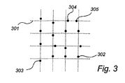
図3に、第二のタイプの位置コーディングパターンを示す。この場合、ラスターパターンを基準とした異なった変位が異なった記号値をコード化する。このラスターパターンは、垂直/水平線301から成っている。しかしながら、実際の応用例では、このラスターパターンは、プリントアウトする必要はない。ドットのこの記号値もまた、パターン中の他のドットを用いて決定することが可能である。図3に示すように、対応するラスター位置(垂直な線と水平な線との交点)の上側、下側、右側及び左側にドットが存在するが、このため、このパターンには四つの互いに異なった記号値が存在する。このパターンは、図2のパターンと類似の方法で用いることが可能である。
FIG. 3 shows a second type of position coding pattern. In this case, different symbol values with different displacements based on the raster pattern are coded. This raster pattern consists of vertical /
図3のパターン中の隣り合った二つのラスター位置同士間の距離は、たとえば、300μmであったりする。ドットは、それぞれのラスター位置から50μm変位していたりする。これによって、隣り合った二つのドット間の最小距離(右側に変位した左側のドットと左側に変位した右側のドットとの距離)が200μmとなる。二つのドット間の次に小さい距離(たとえば、右側に変位した左側のドットと上方に変位した右側のドット間の距離)は、すべてのドットがそれぞれのラスター位置に対して変位していれば、255μmである。この最小距離と次に最小である距離との間の差は、ラスター位置からの変位が大きくなれば又はラスター位置同士間の距離が減少すれば減少するが、この結果、この差が小さ過ぎると、検出の信頼性が劣化する。 The distance between two adjacent raster positions in the pattern of FIG. 3 may be 300 μm, for example. The dots may be displaced by 50 μm from the respective raster positions. As a result, the minimum distance between two adjacent dots (the distance between the left dot displaced to the right and the right dot displaced to the left) is 200 μm. The next smallest distance between two dots (for example, the distance between the left dot displaced to the right and the right dot displaced upward) is that if all the dots are displaced relative to their raster position, 255 μm. The difference between this minimum distance and the next minimum distance decreases as the displacement from the raster position increases or the distance between the raster positions decreases, but as a result, if this difference is too small The reliability of detection deteriorates.
図4に、プリントアウト装置のブロック図を示す。この装置は、従来のタイプのものである。コンピュータユニット401とプリンタユニット402が存在する。これらは、ケーブル408で接続されている。アプリケーション403は、コンピュータ内でアクティブである。このアプリケーション403が位置コーディングパターンのプリントアウトを始動すると、これに関する命令が、位置コーディングパターンを発生するモジュール404に送られる。これによって、全体的又は部分的な図形ファイルが、たとえば、.gif、.jpeg、.bmp、.pdf、.tiffなどの形式で発生される。このファイルは、理想的なパターンを包含していると言うことが可能である。この図形ファイルは会話モジュール405に送られるが、このモジュールは、周知の方法で、たとえば、POSTSCRIPT(登録商標)形式又はPCL(プリンタ制御言語)形式で図形形式をページ記述コードに変換する。コンピュータユニット401中のI/O(入力/出力)モジュール406を用いて、ページ記述コードは、ケーブル408を介して、プリンタユニット402中の対応するI/Oモジュール409に送信される。次に、ページ記述コードは変換モジュール410に転送され、ここで、図形情報に変換されて、プリンタのハードウエア412に対する入力データを構成する。この図形情報は、バッファメモリ411に入力され、これから、プリンタハードウエア412によって読み出される。この図形情報に基づいて、プリンタハードウエア412は、たとえば、紙上にプリントアウトを発生する。
FIG. 4 shows a block diagram of the printout apparatus. This device is of the conventional type. There are a
図5に、本発明のある実施形態による位置コーディングパターンをプリントアウトする装置のブロック図を示す。この装置は、コンピュータユニット501とプリンタユニット502とを備えている。アプリケーション503は、コンピュータユニット501上で実行される。ここで、このアプリケーションは、境界モジュール504に命令を送ることによって、位置コーディングパターンのセクションのプリントアウトを始動する。次に、境界モジュール504は、より大きな、つまり広域にわたる、位置コーディングパターンの中にあるセクションの境界に関する情報を発生する。境界モジュール504はまた、このセクションの理想的な解像度と理想的な密度とに関する情報を発生することも可能である。境界モジュール504によって発生されたこの情報は、プリンタユニット502に対して、たとえば、ケーブル506を介して、また、I/Oモジュール505を用いて送信される。この送信は、他の手段、たとえば、赤外線リンクや短距離無線リンクで実行可能であることが認識されよう。送信された情報は、プリンタユニット502中のI/Oモジュール507によって受信されて、プリンタユニット中のアルゴリズムモジュール508に転送される。このアルゴリズムモジュール508は、コンピュータユニット501中の境界モジュール504からの情報に基づいて図形情報を発生させるが、この図形情報は、広域にわたる位置コーディングパターンのセクション中のパターン記号を記述している。アルゴリズムモジュール508が、解像度やインクタイプなどのプリンタの特性に関するデータ510にアクセスするので、パターン記号を記述する最適な図形情報を発生して、バッファメモリ509に入力することが可能である。その結果、後に詳述する問題が完全に又は部分的に避けられる。加えて、コンピュータユニットからプリンタユニットへの送信がより迅速に行われるが、それは、パターンがプリンタユニット中で発生されるため、送信しなければならない情報量が少なくて済むからである。
FIG. 5 shows a block diagram of an apparatus for printing out a position coding pattern according to an embodiment of the present invention. This apparatus includes a
図4の装置内の場合のように、プリンタユニット502中のプリンタハードウエア511は、バッファメモリ509中の情報に基づいてプリントアウトを発生する。この位置コーディングパターンは、赤外線を吸収するインクを用いてプリントアウトし、他の図形情報は、赤外線を吸収しないインクを用いてプリントアウトするのが望ましい。たとえば、インクジェットプリンタでは、位置コーディングパターンは炭素系インクを用いてプリントアウトし、一方、他の情報は、赤外線を吸収しない黒インクともなり得るRGB(赤、緑、青)の組み合わせ(又はCMY組み合わせ)を用いてプリントアウト可能である。これは、多くのインクジェットプリンタ中に見受けられるインクカートリッジを用いて実行可能であり、これによって、同じ紙の上でテキストや図表などの他の図形情報が干渉を引き起こすことなく、赤外線を用いて位置コーディングパターンを検出することが可能である。図形発生目的で炭素系インクとRGBインクの双方を用いる能力を有する一部のプリンタは、どんな黒色図形に対しても自動的に炭素系インクオプションを選択する。本発明のある好ましい実施形態では、この自動的に動作する機能は、位置コーディングパターンを含む図形が発生されると妨害され、そのため、炭素系インクは位置コーディングパターンだけのためにとって置かれ、RGBオプションは他の黒色図形のために用いられる。
As in the case of the apparatus of FIG. 4, the
プリンタユニットは、位置コーディングパターンのプリントアウト用に適応された紙用に使用されるようになっている給紙トレイを含むことが可能である。プリントアウトに位置コーディングパターンが含まれていると、プリンタは、このトレイから自動的に紙を選択する。これによって、位置コーディングパターンをプリントアウトするために高品質の紙を使用することが可能となる。 The printer unit may include a paper feed tray adapted for use with paper adapted for printing out position coding patterns. If the printout includes a position coding pattern, the printer automatically selects paper from this tray. This makes it possible to use high quality paper to print out the position coding pattern.
図5に示すようなプリンタはもちろん、位置コーディングパターン以外の情報を普通の仕方でプリントアウトするモジュールを備えることが可能である。この構成は、したがって、図5における構成と完全に又は部分的に並行して又は独立に動作する、ページ記述コードを発生して変換するモジュールをさらに備えることが可能である。しかしながら、他の情報に含まれる部分の、位置コーディングパターンを基準とした紙上の位置が、重要である場合、これらの部分をも位置コーディングパターンに適合させることが可能である。 Of course, a printer as shown in FIG. 5 can be provided with a module for printing out information other than the position coding pattern in a normal manner. This arrangement may therefore further comprise a module for generating and converting page description code that operates completely or partially in parallel or independently of the arrangement in FIG. However, the portion included in the other information, the position of the paper relative to the position-coding pattern, may be important, it is possible to also adapt to the position-coding pattern these parts.
アルゴリズムモジュール508は、複数の異なった方法で構成することが可能である。それは、パターンの外観を境界情報に基づいて数学的に計算するシステムで構成することができる。また、アルゴリズムモジュール508に、位置コーディングパターンのより大きな部分、あるいは、より小さな部分の外観に関する情報を含むメモリを備えることが可能である。
The
一般に、図5に示すモジュールは、ハードウエアとソフトウエアの双方を備えることが可能である。 In general, the module shown in FIG. 5 can include both hardware and software.
原則として、プリンタ上に他の視覚情報(たとえば、テキスト、図表、表又は類似物)をプリントアウトするコンピュータユニット以外のソースから、境界情報を得ることが可能である。これで、プリンタは、ボタンなどの操作手段を有することが可能である。この操作手段を起動すると、プリンタのアルゴリズムが起動される(オプションとして、これは永久的に起動させることが可能である)が、これは、コンピュータユニットによって始動されていない状態で、位置コーディングパターンに対応する図形情報を発生する。この図形情報は、プリントアウト中に視覚情報に重畳される。このプリンタは、プリンタに接続されたコンピュータシステムから境界情報を得るように構成できることが望ましいが、このコンピュータシステムは上記のコンピュータユニット以外のものであっても良い。この境界情報は、プリンタ中のアルゴリズムによって用いられる。これによって、局所的に固有のパターン、すなわち、ユーザのグループ内部で(たとえば職場で)固有であるパターンが、プリントアウト用に使用を許可されるから、パターンを手段として実行されるディジタル記録中にパターン内での「衝突」が起きる危険性が回避される。 In principle, other visual information on the printer (e.g., text, charts, tables or the like) from a source other than the computer unit that the printing out, it is possible to obtain boundary information. Thus, the printer can have operation means such as buttons. When this operating means is activated, the printer algorithm is activated (optionally it can be activated permanently), which is not activated by the computer unit, but in the position coding pattern. Corresponding graphic information is generated. This graphic information is superimposed on visual information during printout. Although it is desirable that the printer can be configured to obtain boundary information from a computer system connected to the printer, the computer system may be other than the computer unit described above. This boundary information is used by an algorithm in the printer. Thereby, locally unique pattern, i.e., within a group of users pattern (eg at work) is unique, because is allowed to use for printing out, in a digital recording that runs the pattern as a means the risk of "collision" occurs in the pattern is avoided.
図6に、記号サイズの量子化に伴う問題を示す。プリンタユニットは、必ずしもあらゆるサイズのドットを発生することが可能であるわけではない。プリンタにとっては、プリンタのハードウエアに適合された互いに異なった多くのドットサイズを発生するのが普通である。ドット601、602及び603は、このようなドットサイズの例である。位置コーディングパターンのプリントアウトを、図4に示すような従来の構成を用いて実行すると、必要とされる理想的な記号サイズは、ドットサイズであることが望ましいが、プリンタによって発生することが可能なサイズとは対応しない危険性がある。通常は、ページ記述コードを変換している間に、これらのドットは、最も近いサイズのドットによって置き換えられる、すなわち、ドットのサイズは量子化される。
FIG. 6 illustrates a problem associated with symbol size quantization . The printer unit is not necessarily capable of generating dots of all sizes. For printers, it is common to generate many different dot sizes that are adapted to the printer hardware. The
図2に示すタイプのパターンをプリントアウトすると仮定する。大きいほうの理想的なドット202は、ドット602と603の間のサイズである。小さいほうの理想的ドットタイプ201は、ドット601と602の間のサイズである。最悪シナリオの場合、プリンタユニットは、理想的パターンにおける大きいほうと小さいほうのドットを双方とも、ドット602と同じサイズでプリントアウトする。このようなパターン中のすべての記号は、同じ記号値を有し、このようなパターンは、もちろん、使用不可能である。
Assume that a pattern of the type shown in FIG. 2 is printed out. The larger
ドットサイズの量子化は、図3に示すタイプのパターンにおいても問題を引き起こしかねない。ドットは、高解像度を持つパターン中で大きくしすぎると、一緒になってしまいかねず、このため、パターン中の位置の光学的検出が不可能となりかねない。 Quantization dot size also can cause problems Oite the type of pattern shown in FIG. If the dots are made too large in a pattern with high resolution, they can become together, which can make optical detection of the position in the pattern impossible.
その代わりプリントアウトを図5に示すような本発明による構成で実行すると、アルゴリズムモジュール508のパターンを、プリンタの特性に適するように適合させることが可能である。図2のパターンを持つ例では、たとえば、タイプ601のドットを、小さいドットを表すように選択することが可能であり、タイプ602のドットを、大きいドットを表すように選択することが可能である。
When you run instead printout configuration according to the invention as shown in FIG. 5, the pattern of the
図7に、インクジェットプリンタ上でのプリントアウトに伴う問題を示す。この問題は、高速印刷中に、プリンタヘッドが、紙に対して比較的急速に移動する際に発生する。この問題は、ドット701の背後の“テール”702として顕われている。したがって、このドットは変形しており、この結果、位置コーディングパターン中の位置が不正確に光学的検出されるか又はされずに終わってしまいかねない。本発明のある実施形態による構成では、これは、位置コーディングパターンをプリントアウトする際に印刷速度を落とすことによって回避することが可能である。これを図5に示すが、この場合、アルゴリズムモジュール508によって、プリンタハードウエア511が印刷速度を減少させる。
FIG. 7 shows a problem associated with printout on an inkjet printer. This problem occurs when the printer head moves relatively quickly with respect to the paper during high speed printing . This problem is manifested as a “tail” 702 behind the
図8に、記号変位距離の量子化に伴う問題を示す。プリントアウトにおける解像度は、プリンタによって異なる。これと同じように、たとえば、位置コーディングパターン中のドットを変位させることが可能な最小距離も変動する。800dpi(一インチ当たりのドット数)という解像度のプリンタでは、ドットを変位させることが可能な最小距離は、一インチの1/800である。このため、プリントアウトが制限される。図8では、多くの位置801、802及び803が軸に沿って示されており、これらの位置にドットを配置することが可能である。これらの同士間の距離804が、このプリンタの最小の記号変位距離である。
FIG. 8 shows a problem associated with quantization of the symbol displacement distance. The resolution in printout varies depending on the printer. In the same manner, for example, the minimum distance at which dots in the position coding pattern can be displaced varies. In a printer with a resolution of 800 dpi (dots per inch), the minimum distance that a dot can be displaced is 1 / 800th of an inch. For this reason, printout is limited. In Figure 8, a number of
ドットを理想的には上記の位置の間の位置805に配置しなければならない場合、プリンタは、プリントアウトする際に、この位置を、たとえば、806や807などの可能な位置の内のどれかに変位させる。これには、記号位置の量子化が伴う。このように記号位置を変位させることによって、図3に示すもののような位置コーディングパターンをプリントアウトする際に問題が起こりかねないことが明らかである。これは、記号に与えられる位置が、そのラスター位置を基準として正しくない位置になり得るということと、パターン画像中の他のドットを用いた計算によるラスター位置が、不正確に計算されるということの双方の理由による。この変位はパターン中のすべてのドットに対して同じであると推測することは不可能である。
If the ideal dot must be located at a
こうする代わりに、プリントアウトを図5に示すような本発明による構成で実行すると、アルゴリズムモジュール508のパターンを、プリンタの特性に適するように適合させることが可能である。図3のパターンの例では、ラスター位置同士間の距離と、それぞれのラスター位置に対するドットの変位とは、プリンタの可能な最小の記号変位の整数倍とすることが可能であり、これで、使用可能なパターンをプリントアウトすることが可能となる。
Instead of this, when executing the printout in the configuration according to the invention as shown in FIG. 5, the pattern of the
ある例では、プリンタは、600dpi(これで、最小変位b=42.33μmとなる)で用いられる。図3に示すタイプの理想的なパターンが、プリントアウトされる。この例では、これは、理想的な場合では、ラスター位置同士間の距離が300μmとなり、ラスター位置に対するドットの変位が50μmとなる。図4による従来の方法でプリントアウトすると、その結果、上述したように、パターン記号の変位が一様でなくなり、このため、その結果、位置検出が不正確となる危険性に加えて、目にとって不快なプリントアウト中での干渉パターンが発生する。 In one example, the printer is used at 600 dpi (this results in a minimum displacement b = 42.33 μm). An ideal pattern of the type shown in FIG. 3 is printed out. In this example, in an ideal case, the distance between the raster positions is 300 μm, and the displacement of the dots with respect to the raster positions is 50 μm. When the printout is performed by the conventional method according to FIG. 4, as a result, the displacement of the pattern symbols is not uniform as described above. An unpleasant printout interference pattern occurs.
プリントアウトをプリンタの特性に適合させることによって、プリントアウトを改善することが可能である。どのような制限内でパターンを変更させることが可能であるかを画定する情報が、境界情報に含まれる又は添付されるが、このような情報もまた、プリンタユニット中にストアすることが可能である。たとえば、ドットの変位は、二つのラスター位置同士間の距離の1/8から1/4以内にあるのが望ましい。プリンタの分解能が良好である場合、原則として、ラスター位置の距離とドット変位の距離の選択には多くの組み合わせが可能である。これで、理想的な必要パターンからの逸脱が最も少ないソリューションを選択するのが望ましい。 By adapting the printout to the characteristics of the printer, it is possible to improve the printout. Information that defines within which limits the pattern can be changed is included or appended to the boundary information, but such information can also be stored in the printer unit. is there. For example, the displacement of dots is desirably from 1/8 of the distance between two raster positions with each other to within 1/4. If the resolution of the printer is good, in principle, many combinations are possible for selecting the raster position distance and the dot displacement distance. It is now desirable to select a solution that has the least deviation from the ideal required pattern.
ある実施形態では、ラスター位置同士間の距離は、254μm(6・b)に変更可能である(不変ドット変位)。この調整だけで、干渉パターンがかなり減ったより良好なパターンが発生する。 In some embodiments, the distance between raster positions can be changed to 254 μm (6 · b) (invariant dot displacement). Only this adjustment will produce a better pattern with a much reduced interference pattern.
別の実施形態では、ラスター位置同士間の距離と変位距離との双方が変更される。ラスター位置同士間の距離は296.33μm(7・b)に変更され、変位距離は42.33μm(b)に変更される。これで、まったく干渉のない完全なパターンとなる。別の代替例では、ラスター位置同士間の距離を254μm(6・b)に変更し、変位距離を42.33μm(b)に変更することが可能である。ラスター位置距離とドット変位距離を必要とされる距離から少し調整しただけでも、プリントアウトされた位置コーディングパターンに対してプラス効果があることに注意されたい。 In another embodiment, both the distance between the raster positions and the displacement distance are changed. The distance between the raster positions is changed to 296.33 μm (7 · b), and the displacement distance is changed to 42.33 μm (b). This gives a complete pattern with no interference. In another alternative, the distance between raster positions can be changed to 254 μm (6 · b) and the displacement distance can be changed to 42.33 μm (b). Note that a slight adjustment of the raster position distance and dot displacement distance from the required distances has a positive effect on the printed position coding pattern.
変位距離が下方に調整されるような場合においては、必要に応じてドットサイズを減少させ、これで、ドットが自身のラスター位置を覆わないようにすると利点となり得る。 In cases where the displacement distance is adjusted downwards, it may be advantageous to reduce the dot size as necessary, so that the dots do not cover their raster position.
図9に、本発明のある実施形態による方法900のフローチャートを示す。
FIG. 9 shows a flowchart of a
第一のステップ901では、境界情報がコンピュータユニット中で発生されるが、この境界情報は、広域にわたる位置コーディングパターン中のセクションの境界を記述している。
In a
セクションが平面曲線の形状であれば、境界情報は、この曲線のパラメータ表示を含むことが可能である。 If the section is in the shape of a planar curve, the boundary information can include a parameter representation of this curve.
セクションが矩形の形状であれば、対応する境界情報は、この矩形の二つの対角線上の互いに対抗するコーナーに対する位置コーディングパターン中の位置を含むことが可能である。 If the section is rectangular in shape, the corresponding boundary information can include a position in the position coding pattern for the opposite corners of the rectangle on the two diagonals.
セクションが多角形の形状であれば、対応する境界情報は、この多角形のコーナーに対する位置コーディングパターン中の位置を含むことが可能である。この多角形は、等辺の多角形である必要はないが、何か別様に等辺であったり対称形であったりすれば、この多角形のコーナーの数より少ない数の位置表示でしばしば十分である。 If the section is a polygonal shape, the corresponding boundary information can include a position in the position coding pattern for this polygonal corner. This polygon need not be an equilateral polygon, but if it is otherwise equilateral or symmetrical, it is often sufficient to display fewer positions than the number of corners of the polygon. is there.
セクションが円の形状であれば、対応する境界情報は、この円の中心に対する位置コーディングパターン中の位置と、この円の直径に関連する情報とを含むことが可能である。 If the section is a circle shape, the corresponding boundary information can include a position in the position coding pattern relative to the center of the circle and information related to the diameter of the circle.
セクションが楕円の形状であれば、対応する境界情報は、この楕円の焦点に対する位置コーディングパターン中の位置と、一方ではこの楕円の焦点の各々と他方ではこの楕円の周辺上の所与の点との間の合計距離に関連する情報とを含むことが可能である。 If the section is elliptical, the corresponding boundary information is the position in the position-coding pattern for the ellipse focus, on the one hand each of the ellipse focus and on the other hand a given point on the periphery of the ellipse. Information related to the total distance between.
第二のステップ902では、境界情報がコンピュータユニットからプリンタユニットに送信される。この境界情報と一緒に、パターンの他の特性に関連する情報、たとえば、ドットサイズを送信することが可能である。
In a
いくつかのセクションを一つの同じベース上にプリントアウトすることが可能である。このため、いくつかの集合を成す境界情報を、コンピュータユニットからプリンタユニットに送信する。これらの互いに異なったセクションは、広域にわたる位置コーディングパターンの別々の部分から発生させることが可能である。 Several sections can be printed out on one and the same base. For this reason, boundary information forming several sets is transmitted from the computer unit to the printer unit. These different sections can be generated from separate parts of the global location coding pattern.
第三のステップ903では、広域にわたる位置コーディングパターンを画定するアルゴリズムによって、また、境界情報に基づいてプリンタユニット中で図形情報を発生するが、この図形情報は、セクション中のパターン記号を記述する。オプションとして、このアルゴリズムもまた、コンピュータユニットからプリンタに送信することが可能である。よって、このアルゴリズムは、ページ記述コードで書くことが可能である。
In a
第四のステップ904では、この図形情報が、プリンタユニットによってベース上にプリントアウトされる。
In a
本発明は、上記の実施形態に限られることはなく、添付クレームの範囲内で変更可能である。 The present invention is not limited to the above-described embodiment, and can be modified within the scope of the appended claims.
Claims (26)
前記コンピュータユニットにおいて、広域にわたる位置コーディングパターン中のプリントアウトされるべきセクションの境界を記述する境界情報を生成し、
前記境界情報を前記コンピュータユニットから前記プリンタユニットに送信し、
前記プリンタユニットにおいて、前記広域にわたる位置コーディングパターンを画定するアルゴリズムを用い、該アルゴリズムが前記境界情報を用いることにより、前記セクション内の位置コーディングパターンの記号を記述する図形情報を生成し、
前記プリンタユニットによって前記図形情報をベース上にプリントアウトすることを特徴とする方法。A computer unit, in a system that includes a printer unit connected to the computer unit, a method of creating a base having a position-coding pattern,
In said computer unit, generating boundary information describing the boundaries of the section to be printed out in the wide area position coding pattern ;
Transmitting the boundary information from the computer unit to the printer unit ;
In the printer unit, an algorithm that defines the position coding pattern over the wide area is used , and the algorithm uses the boundary information to generate graphic information describing a symbol of the position coding pattern in the section ;
A method of printing out the graphic information on a base by the printer unit.
前記プリンタユニットが、前記アルゴリズムによって、前記パターン品質仕様に基づいてプリンタパラメータを適合させるものである、請求項1〜5のいずれか1項に記載の方法。The computer unit, and transmits a pattern quality specification required for the printer unit,
The method according to claim 1 , wherein the printer unit is adapted to adapt printer parameters based on the pattern quality specification according to the algorithm.
広域にわたる位置コーディングパターン中のプリントアウトされるべきセクションの境界を記述する境界情報を生成する手段を、前記コンピュータユニットに備え、
前記境界情報を前記コンピュータユニットから前記プリンタユニットに送信する手段を備え、
前記広域にわたる位置コーディングパターンを画定するアルゴリズムを用い、該アルゴリズムが前記境界情報を用いることにより、前記セクション内の位置コーディングパターンの記号を記述する図形情報を生成する手段と、この図形情報をベース上にプリントアウトする手段とを、前記プリンタユニットに備えることを特徴とするシステム。 A system comprising a computer unit and a printer unit connected to the computer unit ,
Means for generating boundary information describing a boundary of a section to be printed out in a global position-coding pattern, the computer unit comprising:
Means for transmitting the boundary information from the computer unit to the printer unit ;
Means for generating graphic information describing a symbol of the position coding pattern in the section by using an algorithm that defines the position coding pattern over the wide area , and the algorithm uses the boundary information ; The printer unit is provided with means for printing out to the printer unit .
前記コンピュータユニットから、広域にわたる位置コーディングパターン中のプリントアウトされるべきセクションの境界を記述する境界情報を、受信する手段と、
前記広域にわたる位置コーディングパターンを画定するアルゴリズムを用い、該アルゴリズムが前記境界情報を用いることにより、前記セクション内の位置コーディングパターンの記号を記述する図形情報を生成する手段と、
前記図形情報をベース上にプリントアウトする手段とを備えることを特徴とするプリンタデバイス。 A printer device adapted to be connected to a computer unit ,
Means for receiving from the computer unit boundary information describing the boundaries of the section to be printed out in a wide area position coding pattern ;
Means for generating graphical information describing a symbol of the position coding pattern in the section by using an algorithm that defines the position coding pattern over the wide area, the algorithm using the boundary information ;
A printer device comprising: means for printing out the graphic information on a base.
広域にわたる位置コーディングパターン中のプリントアウトされるべきセクションの境界を記述する境界情報を生成するための命令と、
前記境界情報を前記コンピュータユニットから前記プリンタユニットに送信するための命令とを有し、
前記プリンタユニットが、前記広域にわたる位置コーディングパターンを画定するアルゴリズムを用い、該アルゴリズムが前記境界情報を用いることにより、前記セクション内の位置コーディングパターンの記号を記述する図形情報を生成して、この図形情報をベース上にプリントアウトするようになっていることを特徴とするコンピュータプログラム。 A computer program used in a system comprising a computer unit and a printer unit connected to the computer unit ,
Instructions for generating boundary information describing the boundaries of the section to be printed out in the global position coding pattern ;
A command for transmitting the boundary information from the computer unit to the printer unit ;
Said printer unit, using an algorithm that defines the position-coding pattern over the wide area, by the algorithm using said boundary information, and generates the graphic information to describe the symbol position-coding pattern in said section, this shape A computer program for printing out information on a base.
広域にわたる位置コーディングパターン中のプリントアウトされるべきセクションの境界を記述する境界情報を取得する手段と、
前記広域にわたる位置コーディングパターンを画定するアルゴリズムを保持する手段と、
操作手段と、
前記操作手段が起動されると、前記アルゴリズムを起動し、該アルゴリズムが前記境界情報を用いることにより、前記セクション内の位置コーディングパターンに対応する図形情報を生成し、この図形情報を前記視覚情報に重畳してプリントアウトする手段とを備えることを特徴とするプリンタ。 What printer der to print out the visual information,
Means for obtaining boundary information describing the boundaries of a section to be printed out in a global location coding pattern;
Means for holding an algorithm for defining the global location coding pattern;
Operation means ;
When the operating means is activated, start the algorithm, by the algorithm using said boundary information to generate the graphical information corresponding to the position-coding pattern in said section, the graphical information on the visual information And a printer for superimposing and printing out .
Applications Claiming Priority (2)
| Application Number | Priority Date | Filing Date | Title |
|---|---|---|---|
| SE0101208A SE519012C2 (en) | 2001-04-05 | 2001-04-05 | Ways to handle information |
| PCT/SE2002/000660 WO2002082366A1 (en) | 2001-04-05 | 2002-04-04 | Method for processing information |
Related Child Applications (1)
| Application Number | Title | Priority Date | Filing Date |
|---|---|---|---|
| JP2008152006A Division JP4815472B2 (en) | 2001-04-05 | 2008-06-10 | How to process information |
Publications (3)
| Publication Number | Publication Date |
|---|---|
| JP2004528644A JP2004528644A (en) | 2004-09-16 |
| JP2004528644A5 JP2004528644A5 (en) | 2008-10-02 |
| JP4215516B2 true JP4215516B2 (en) | 2009-01-28 |
Family
ID=20283674
Family Applications (3)
| Application Number | Title | Priority Date | Filing Date |
|---|---|---|---|
| JP2002580255A Expired - Fee Related JP4215516B2 (en) | 2001-04-05 | 2002-04-04 | How to process information |
| JP2008152006A Expired - Fee Related JP4815472B2 (en) | 2001-04-05 | 2008-06-10 | How to process information |
| JP2011131351A Expired - Lifetime JP5323893B2 (en) | 2001-04-05 | 2011-06-13 | How to process information |
Family Applications After (2)
| Application Number | Title | Priority Date | Filing Date |
|---|---|---|---|
| JP2008152006A Expired - Fee Related JP4815472B2 (en) | 2001-04-05 | 2008-06-10 | How to process information |
| JP2011131351A Expired - Lifetime JP5323893B2 (en) | 2001-04-05 | 2011-06-13 | How to process information |
Country Status (7)
| Country | Link |
|---|---|
| EP (1) | EP1380008B1 (en) |
| JP (3) | JP4215516B2 (en) |
| CN (1) | CN1294525C (en) |
| AT (1) | ATE386991T1 (en) |
| DE (1) | DE60225126T2 (en) |
| SE (1) | SE519012C2 (en) |
| WO (1) | WO2002082366A1 (en) |
Cited By (2)
| Publication number | Priority date | Publication date | Assignee | Title |
|---|---|---|---|---|
| US8724160B2 (en) | 2011-09-21 | 2014-05-13 | Fuji Xerox Co., Ltd. | Image forming apparatus, image forming system, and non-transitory computer readable medium storing control program |
| US8953212B2 (en) | 2011-08-22 | 2015-02-10 | Fuji Xerox Co., Ltd. | Image forming apparatus and method, image forming system, and computer readable medium |
Families Citing this family (28)
| Publication number | Priority date | Publication date | Assignee | Title |
|---|---|---|---|---|
| SE0301548D0 (en) * | 2003-05-26 | 2003-05-26 | Anoto Ab | on-demand printing or coding patterns |
| JP4406430B2 (en) | 2003-05-26 | 2010-01-27 | アノト アクティエボラーク | Method for compressing a digital representation containing page description code sent from a computer to a printer |
| KR20060024410A (en) * | 2003-06-13 | 2006-03-16 | 아노토 아이피 엘아이씨 에이치비 | On-demand printing of coding patterns |
| SE0301729D0 (en) * | 2003-06-13 | 2003-06-13 | Anoto Ab | Need-controlled printing of coding patterns |
| GB0321164D0 (en) | 2003-09-10 | 2003-10-08 | Hewlett Packard Development Co | Methods,apparatus and software for printing location pattern |
| GB0321170D0 (en) * | 2003-09-10 | 2003-10-08 | Hewlett Packard Development Co | Generation and processing of position identification pattern |
| US6962450B2 (en) | 2003-09-10 | 2005-11-08 | Hewlett-Packard Development Company L.P. | Methods and apparatus for generating images |
| GB0321168D0 (en) | 2003-09-10 | 2003-10-08 | Hewlett Packard Development Co | Printing of documents with position identification pattern |
| US20050052700A1 (en) * | 2003-09-10 | 2005-03-10 | Andrew Mackenzie | Printing digital documents |
| EP1690215A1 (en) | 2003-11-18 | 2006-08-16 | Anoto IP Lic HB | Methods and arrangement in an information management system |
| SE0303058D0 (en) | 2003-11-18 | 2003-11-18 | Anoto Ab | Methods and arrangements in an information management system |
| SE0400322D0 (en) * | 2004-02-13 | 2004-02-13 | Anoto Ab | On-demand printing or coding patterns |
| GB2412215B (en) | 2004-03-18 | 2008-08-13 | Hewlett Packard Development Co | Position identification pattern |
| US8054495B2 (en) | 2004-04-07 | 2011-11-08 | Hewlett-Packard Development Company, L.P. | Digital documents, apparatus, methods and software relating to associating an identity of paper printed with digital pattern with equivalent digital documents |
| JP2006293773A (en) * | 2005-04-12 | 2006-10-26 | Ricoh Co Ltd | Electronic document converting device |
| JP4569397B2 (en) | 2005-06-15 | 2010-10-27 | 富士ゼロックス株式会社 | Electronic document management system, image forming apparatus, electronic document management method, and program |
| JP4529828B2 (en) | 2005-07-19 | 2010-08-25 | 富士ゼロックス株式会社 | Document falsification prevention device |
| JP4609218B2 (en) | 2005-07-19 | 2011-01-12 | 富士ゼロックス株式会社 | Image forming apparatus, control method thereof, and program |
| JP4618042B2 (en) | 2005-08-10 | 2011-01-26 | 富士ゼロックス株式会社 | Printing system, printing apparatus, printing processing method, and program |
| JP4586677B2 (en) | 2005-08-24 | 2010-11-24 | 富士ゼロックス株式会社 | Image forming apparatus |
| JP2007296742A (en) * | 2006-04-28 | 2007-11-15 | Fuji Xerox Co Ltd | Image forming apparatus and method for managing electronic document |
| JP4670740B2 (en) | 2006-06-07 | 2011-04-13 | 富士ゼロックス株式会社 | Image generating apparatus, image processing system, and program |
| EP2138960A1 (en) * | 2008-06-27 | 2009-12-30 | Anoto AB | A method and a device for controlling printing of graphical information |
| JP2010130463A (en) * | 2008-11-28 | 2010-06-10 | Oki Data Corp | Print data generation apparatus, printing device, and print data processing system |
| KR101923253B1 (en) | 2011-09-28 | 2018-11-28 | 다이니폰 인사츠 가부시키가이샤 | Pattern-printed sheet and manufacturing method therefor |
| GB2526261B (en) | 2014-04-28 | 2017-08-02 | Gelliner Ltd | Encoded cells and cell arrays |
| CN108664961A (en) * | 2017-04-02 | 2018-10-16 | 田雪松 | File output method with position encoded pattern |
| CN108664224A (en) * | 2017-04-02 | 2018-10-16 | 田雪松 | Coding pattern processing method and processing device |
Family Cites Families (17)
| Publication number | Priority date | Publication date | Assignee | Title |
|---|---|---|---|---|
| US5852434A (en) | 1992-04-03 | 1998-12-22 | Sekendur; Oral F. | Absolute optical position determination |
| JP3277052B2 (en) * | 1993-11-19 | 2002-04-22 | シャープ株式会社 | Coordinate input device and coordinate input method |
| US5661506A (en) | 1994-11-10 | 1997-08-26 | Sia Technology Corporation | Pen and paper information recording system using an imaging pen |
| JPH09152945A (en) * | 1995-11-30 | 1997-06-10 | Canon Inc | Information processor, printer device, printing system, and method for processing data of printing system |
| US6098882A (en) * | 1996-03-01 | 2000-08-08 | Cobblestone Software, Inc. | Variable formatting of digital data into a pattern |
| JP3010136B2 (en) * | 1996-03-28 | 2000-02-14 | オリンパス光学工業株式会社 | Code data output device |
| JPH10187395A (en) * | 1996-12-27 | 1998-07-14 | Casio Comput Co Ltd | Printer driver and storage medium and printing system using the same |
| AUPO939997A0 (en) * | 1997-09-23 | 1997-10-16 | Silverbrook Research Pty Ltd | Data processing method and apparatus (ART61) |
| JPH11265419A (en) * | 1998-03-16 | 1999-09-28 | Toshiba Corp | Method and system for optimizing bar code print and recording medium for and recording the programmed method |
| WO1999050736A1 (en) * | 1998-04-01 | 1999-10-07 | Xerox Corporation | Paper indexing of recordings |
| JPH11301077A (en) * | 1998-04-23 | 1999-11-02 | Olympus Optical Co Ltd | Apparatus and method for evaluating dot code |
| JP3087845B2 (en) * | 1998-10-02 | 2000-09-11 | 秀一 藤井 | Digital image processing method for reading an original image with a scanner and enlarging and printing |
| JP2000211204A (en) * | 1999-01-28 | 2000-08-02 | Oki Data Corp | Image processor |
| BR0014156A (en) * | 1999-08-30 | 2002-05-14 | Anoto Ab | Notepad |
| SE517445C2 (en) * | 1999-10-01 | 2002-06-04 | Anoto Ab | Position determination on a surface provided with a position coding pattern |
| SE0000950L (en) * | 2000-03-21 | 2001-09-22 | Anoto Ab | Devices and methods related to images |
| SE519356C2 (en) * | 2000-04-05 | 2003-02-18 | Anoto Ab | Procedure and apparatus for information management |
-
2001
- 2001-04-05 SE SE0101208A patent/SE519012C2/en not_active IP Right Cessation
-
2002
- 2002-04-04 CN CNB028091094A patent/CN1294525C/en not_active Expired - Fee Related
- 2002-04-04 AT AT02718755T patent/ATE386991T1/en not_active IP Right Cessation
- 2002-04-04 DE DE60225126T patent/DE60225126T2/en not_active Expired - Lifetime
- 2002-04-04 WO PCT/SE2002/000660 patent/WO2002082366A1/en active IP Right Grant
- 2002-04-04 EP EP02718755A patent/EP1380008B1/en not_active Expired - Lifetime
- 2002-04-04 JP JP2002580255A patent/JP4215516B2/en not_active Expired - Fee Related
-
2008
- 2008-06-10 JP JP2008152006A patent/JP4815472B2/en not_active Expired - Fee Related
-
2011
- 2011-06-13 JP JP2011131351A patent/JP5323893B2/en not_active Expired - Lifetime
Cited By (2)
| Publication number | Priority date | Publication date | Assignee | Title |
|---|---|---|---|---|
| US8953212B2 (en) | 2011-08-22 | 2015-02-10 | Fuji Xerox Co., Ltd. | Image forming apparatus and method, image forming system, and computer readable medium |
| US8724160B2 (en) | 2011-09-21 | 2014-05-13 | Fuji Xerox Co., Ltd. | Image forming apparatus, image forming system, and non-transitory computer readable medium storing control program |
Also Published As
| Publication number | Publication date |
|---|---|
| JP2011198387A (en) | 2011-10-06 |
| JP2004528644A (en) | 2004-09-16 |
| DE60225126D1 (en) | 2008-04-03 |
| EP1380008A1 (en) | 2004-01-14 |
| DE60225126T2 (en) | 2009-02-19 |
| SE0101208D0 (en) | 2001-04-05 |
| JP5323893B2 (en) | 2013-10-23 |
| EP1380008B1 (en) | 2008-02-20 |
| SE0101208L (en) | 2002-10-06 |
| ATE386991T1 (en) | 2008-03-15 |
| CN1294525C (en) | 2007-01-10 |
| CN1505801A (en) | 2004-06-16 |
| SE519012C2 (en) | 2002-12-23 |
| JP4815472B2 (en) | 2011-11-16 |
| JP2008282411A (en) | 2008-11-20 |
| WO2002082366A1 (en) | 2002-10-17 |
Similar Documents
| Publication | Publication Date | Title |
|---|---|---|
| JP4215516B2 (en) | How to process information | |
| US8107092B2 (en) | Method and device for preparing a printout of a position-coding pattern | |
| US20050052700A1 (en) | Printing digital documents | |
| US20050053405A1 (en) | Methods and apparatus for generating images | |
| KR101062107B1 (en) | Method for compressing a digital representation containing a page-describing code, which is sent from a computer to a printer | |
| JP4562740B2 (en) | On-demand printing of coding patterns | |
| JP2006268758A (en) | Printing system, printer, and handwritten information reflecting method | |
| US8477368B2 (en) | Printing apparatus and print data processing system combining stored pattern-based print drawing data with newly-received print drawing data | |
| JP2014049774A (en) | Image processing apparatus, image processing method, image recording apparatus, and program | |
| JP4420252B2 (en) | Print data generator | |
| JP2003011458A5 (en) | ||
| JP6060534B2 (en) | Image processing apparatus, image processing system, and printing method | |
| JP4872924B2 (en) | Image data forming method and image data forming apparatus | |
| JP2006281597A (en) | Image forming apparatus and its program | |
| JP5742449B2 (en) | Image processing apparatus and image processing program | |
| JP6507809B2 (en) | Printing instruction device, printing system and program | |
| JP2009181514A (en) | Handwriting information creation device, program, and handwriting information management system | |
| EP4109869A1 (en) | Document determination system, document determination method, and information processing apparatus | |
| JP4289263B2 (en) | Image generating apparatus, image generating method, program, and storage medium | |
| JP2006281598A (en) | Image forming apparatus and its program | |
| JP4956594B2 (en) | Print data generator | |
| JP2020135262A (en) | Printer control system, printing system, and printing data creation method | |
| JP2007286988A (en) | Printing system | |
| JP2009252063A (en) | Writing information generating device and program | |
| JP2015023348A (en) | Image processing apparatus and image processing program |
Legal Events
| Date | Code | Title | Description |
|---|---|---|---|
| A621 | Written request for application examination |
Free format text: JAPANESE INTERMEDIATE CODE: A621 Effective date: 20041224 |
|
| A711 | Notification of change in applicant |
Free format text: JAPANESE INTERMEDIATE CODE: A711 Effective date: 20050207 |
|
| A711 | Notification of change in applicant |
Free format text: JAPANESE INTERMEDIATE CODE: A711 Effective date: 20060428 |
|
| A521 | Request for written amendment filed |
Free format text: JAPANESE INTERMEDIATE CODE: A523 Effective date: 20060629 |
|
| RD03 | Notification of appointment of power of attorney |
Free format text: JAPANESE INTERMEDIATE CODE: A7423 Effective date: 20070521 |
|
| A977 | Report on retrieval |
Free format text: JAPANESE INTERMEDIATE CODE: A971007 Effective date: 20070720 |
|
| RD04 | Notification of resignation of power of attorney |
Free format text: JAPANESE INTERMEDIATE CODE: A7424 Effective date: 20070703 |
|
| RD04 | Notification of resignation of power of attorney |
Free format text: JAPANESE INTERMEDIATE CODE: A7424 Effective date: 20071016 |
|
| A072 | Dismissal of procedure [no reply to invitation to correct request for examination] |
Free format text: JAPANESE INTERMEDIATE CODE: A073 Effective date: 20071204 |
|
| A131 | Notification of reasons for refusal |
Free format text: JAPANESE INTERMEDIATE CODE: A131 Effective date: 20071211 |
|
| A601 | Written request for extension of time |
Free format text: JAPANESE INTERMEDIATE CODE: A601 Effective date: 20080306 |
|
| A602 | Written permission of extension of time |
Free format text: JAPANESE INTERMEDIATE CODE: A602 Effective date: 20080313 |
|
| A601 | Written request for extension of time |
Free format text: JAPANESE INTERMEDIATE CODE: A601 Effective date: 20080409 |
|
| A602 | Written permission of extension of time |
Free format text: JAPANESE INTERMEDIATE CODE: A602 Effective date: 20080416 |
|
| A601 | Written request for extension of time |
Free format text: JAPANESE INTERMEDIATE CODE: A601 Effective date: 20080507 |
|
| A602 | Written permission of extension of time |
Free format text: JAPANESE INTERMEDIATE CODE: A602 Effective date: 20080514 |
|
| A524 | Written submission of copy of amendment under article 19 pct |
Free format text: JAPANESE INTERMEDIATE CODE: A524 Effective date: 20080609 |
|
| TRDD | Decision of grant or rejection written | ||
| A01 | Written decision to grant a patent or to grant a registration (utility model) |
Free format text: JAPANESE INTERMEDIATE CODE: A01 Effective date: 20081007 |
|
| A01 | Written decision to grant a patent or to grant a registration (utility model) |
Free format text: JAPANESE INTERMEDIATE CODE: A01 |
|
| A61 | First payment of annual fees (during grant procedure) |
Free format text: JAPANESE INTERMEDIATE CODE: A61 Effective date: 20081104 |
|
| R150 | Certificate of patent or registration of utility model |
Free format text: JAPANESE INTERMEDIATE CODE: R150 |
|
| FPAY | Renewal fee payment (event date is renewal date of database) |
Free format text: PAYMENT UNTIL: 20111114 Year of fee payment: 3 |
|
| S531 | Written request for registration of change of domicile |
Free format text: JAPANESE INTERMEDIATE CODE: R313531 |
|
| FPAY | Renewal fee payment (event date is renewal date of database) |
Free format text: PAYMENT UNTIL: 20111114 Year of fee payment: 3 |
|
| R350 | Written notification of registration of transfer |
Free format text: JAPANESE INTERMEDIATE CODE: R350 |
|
| FPAY | Renewal fee payment (event date is renewal date of database) |
Free format text: PAYMENT UNTIL: 20111114 Year of fee payment: 3 |
|
| S531 | Written request for registration of change of domicile |
Free format text: JAPANESE INTERMEDIATE CODE: R313531 |
|
| FPAY | Renewal fee payment (event date is renewal date of database) |
Free format text: PAYMENT UNTIL: 20111114 Year of fee payment: 3 |
|
| R350 | Written notification of registration of transfer |
Free format text: JAPANESE INTERMEDIATE CODE: R350 |
|
| FPAY | Renewal fee payment (event date is renewal date of database) |
Free format text: PAYMENT UNTIL: 20121114 Year of fee payment: 4 |
|
| FPAY | Renewal fee payment (event date is renewal date of database) |
Free format text: PAYMENT UNTIL: 20121114 Year of fee payment: 4 |
|
| FPAY | Renewal fee payment (event date is renewal date of database) |
Free format text: PAYMENT UNTIL: 20131114 Year of fee payment: 5 |
|
| LAPS | Cancellation because of no payment of annual fees |