JP4211891B2 - Game machine - Google Patents
Game machine Download PDFInfo
- Publication number
- JP4211891B2 JP4211891B2 JP2005182803A JP2005182803A JP4211891B2 JP 4211891 B2 JP4211891 B2 JP 4211891B2 JP 2005182803 A JP2005182803 A JP 2005182803A JP 2005182803 A JP2005182803 A JP 2005182803A JP 4211891 B2 JP4211891 B2 JP 4211891B2
- Authority
- JP
- Japan
- Prior art keywords
- display device
- game board
- main body
- liquid crystal
- crystal display
- Prior art date
- Legal status (The legal status is an assumption and is not a legal conclusion. Google has not performed a legal analysis and makes no representation as to the accuracy of the status listed.)
- Expired - Fee Related
Links
Images


Landscapes
- Pinball Game Machines (AREA)
- Display Devices Of Pinball Game Machines (AREA)
Description
本発明は、遊技機に関し、特に表示装置および遊技盤の本体への取付構造に関するものである。 The present invention relates to a gaming machine, and more particularly to a structure for mounting a display device and a game board to a main body.
遊技機、特にパチンコ遊技機においては、パチンコ遊技の興趣を高め、遊技者を飽きさせないように各種の役物や表示装置などに工夫を凝らした遊技盤が使用されている。 In gaming machines, in particular pachinko gaming machines, game boards are used that have been devised for various kinds of objects and display devices so as to enhance the interest of pachinko games and prevent the player from getting bored.
また、パチンコ遊技機では、遊技球が転動流下する遊技領域を備えた遊技盤が備えられている。この遊技盤の背面側には、特別図柄など遊技に関する視覚的な情報を表示する表示装置が配置されており、遊技盤に形成された表示窓を通して、あるいは透明な遊技盤を通して、視認可能になっている。 In addition, the pachinko gaming machine is provided with a game board having a game area in which a game ball rolls down. On the back side of this game board, a display device that displays visual information about the game such as special symbols is arranged, and it can be seen through a display window formed on the game board or through a transparent game board. ing.
ここで、例えば特開2004−249139号公報では、本体に設けられた遊技盤取り付け枠に対して、遊技盤を遊技盤固定部材を用いて取り付ける技術が開示さている。具体的には、遊技盤固定部材は、遊技盤を固定した状態から固定を解除した状態まで動く際に、遊技盤固定部材の外枠内に位置する部分が動く領域よりも遊技盤固定部材の外方側に遊技盤固定部材付近の外枠内面が位置することとなるように設けられている。
しかしながら、上記従来の遊技機では、遊技盤固定部材は遊技盤を固定するためだけに限定的に用いられるので、汎用性に乏しく、部品点数の増加を招いていた。 However, in the above conventional gaming machine, the game board fixing member is limitedly used only for fixing the game board, so that the versatility is poor and the number of parts is increased.
そこで、本発明は、遊技盤固定部材の汎用性を図ることのできる遊技機を提供することを目的とする。 Therefore, an object of the present invention is to provide a gaming machine that can achieve versatility of a game board fixing member.
上記課題を解決するため、請求項1に記載の本発明の遊技機は、遊技球が転動流下する遊技領域を備えた遊技盤と、前記遊技盤の背面側に配置され、所定の画像を表示する表示装置と、前記遊技盤および前記表示装置が取り付けられる本体と、前記本体に設けられ、前記表示装置の前面上部を覆うとともに前記表示装置の前面側で前記遊技盤を前記本体へ係止する係止部と、前記本体に設けられ、前記表示装置の下端が載置されて当該表示装置の下端を支持する支持部とを有し、前記表示装置は、前記本体に対して前方向から取り付けられ、下端が前記支持部に載置された状態で前面上部が前記係止部により前方向への動きが規制されることにより前記本体へ仮固定される、ことを特徴とする。 In order to solve the above-described problem, a gaming machine according to the first aspect of the present invention includes a gaming board having a gaming area in which a gaming ball rolls down, and a rear surface side of the gaming board, and a predetermined image is displayed. A display device for displaying; a main body to which the game board and the display device are attached; and a main body provided on the main body, covering an upper front portion of the display device and locking the game board to the main body on the front side of the display device And a support portion that is provided on the main body and that supports the lower end of the display device by placing the lower end of the display device on the main body. The front upper portion is temporarily fixed to the main body by being attached to the lower end and placed on the support portion, and the forward movement is restricted by the locking portion.
このように、本体に備えられた係止部と支持部とによって遊技盤の係止(すなわち固定)と表示装置の仮固定とが行われるので、遊技盤固定部材としての係止部の機能が表示装置の仮固定にまで広がり、汎用性の向上を図ることが可能になる。
表示装置は本体に対して前方向から取り付けられるので、着脱作業の際に、電子部品の搭載された基板等が障害とならず、容易に着脱作業を行うことができる。
表示装置の一部を係止部で覆うようにするだけで表示装置の取り付け方向である前方向への動きが規制されるので、表示装置の仮固定を容易に行うことが可能になる。
係止部によって表示装置の前面上部が覆われるようになっているので、表示装置が前方向(手前側)に倒れにくくなり、表示装置の本体に対する仮固定を安定させることが可能になる。
表示装置の前面上部を係止部に係止させるとともに、表示装置の下端を支持部に載置させることで、当該表示装置の本体に対する仮固定が行われるようになっているので、係止部による表示装置の上端の係止および下端の載置のみで、表示装置の本体に対する仮固定を行うことができ、表示装置を本体に仮固定するための作業スペースを抑制することができるとともに、表示装置を本体に仮固定するための部材等の設置スペースを抑制することが可能になる。
Thus, since the game board is locked (that is, fixed) and the display device is temporarily fixed by the lock part and the support part provided in the main body, the function of the lock part as the game board fixing member is achieved. The display device can be temporarily fixed, and versatility can be improved.
Since the display device is attached to the main body from the front direction, the substrate on which the electronic component is mounted does not become an obstacle during the attachment / detachment operation, and the attachment / detachment operation can be easily performed.
Since the forward movement, which is the mounting direction of the display device, is restricted only by covering a part of the display device with the locking portion, the display device can be easily temporarily fixed.
Since the upper part of the front surface of the display device is covered by the locking portion, the display device is less likely to fall forward (front side), and the temporary fixing of the display device to the main body can be stabilized.
Since the front upper portion of the display device is locked to the locking portion, and the lower end of the display device is placed on the support portion, temporary fixing to the main body of the display device is performed. The display device can be temporarily fixed to the main body of the display device only by locking the upper end of the display device and placing the lower end of the display device, and the work space for temporarily fixing the display device to the main body can be reduced. It becomes possible to suppress the installation space of a member or the like for temporarily fixing the apparatus to the main body.
請求項2に記載の本発明は、請求項1に記載の発明の構成に加えて、前記本体の前面には、前記表示装置を収容して取り付けるための凹部が形成され、前記凹部の上部には、前方に突出して前記表示装置の上方向への移動を規制する上方向移動規制段部が設けられ、前記係止部は、前記表示装置を仮固定したときに前記係止部により当該表示装置の前面上部が覆われる長さだけ前記上方向移動規制段部の下面よりも下方に突出して設けられている、ことを特徴とする。 According to a second aspect of the present invention, in addition to the configuration of the first aspect of the present invention, a concave portion for accommodating and attaching the display device is formed on the front surface of the main body, and the upper portion of the concave portion is formed. Is provided with an upward movement restricting step that protrudes forward and restricts upward movement of the display device, and the locking portion is displayed by the locking portion when the display device is temporarily fixed. The apparatus is characterized in that it is provided so as to protrude downward from the lower surface of the upward movement restricting stepped portion by a length that covers the upper front portion of the apparatus.
表示装置は上方向移動規制段部によって上方向の移動が規制されるので、表示装置を安定した固定状態に維持できるとともに、上方向移動規制段部により本体の剛性を更に大きくすることができる。 Since the upward movement of the display device is restricted by the upward movement restricting step portion, the display device can be maintained in a stable fixed state, and the rigidity of the main body can be further increased by the upward movement restricting step portion.
請求項3に記載の本発明は、請求項2に記載の発明の構成に加えて、前記凹部には複数の孔が形成されている、ことを特徴とする。
The present invention described in
これにより、本体の内側に滞留する熱を複数の孔から放熱させることができるので、放熱効果を向上させることが可能になる。 Thereby, since the heat staying inside the main body can be radiated from the plurality of holes, the heat radiation effect can be improved.
請求項4に記載の本発明は、請求項請求項1、2または3記載の発明の構成に加えて、前記表示装置にはネジ穴が、前記本体には当該ネジ穴に対応した取付ボスが、それぞれ設けられ、前記表示装置が前記本体に仮固定された位置において、前記表示装置に設けられたネジ穴と前記本体に設けられた取付ボスとが一致する、ことを特徴とする。 According to a fourth aspect of the present invention, in addition to the configuration of the first, second, or third aspect, the display device has a screw hole, and the main body has a mounting boss corresponding to the screw hole. The screw holes provided in the display device and the mounting boss provided in the main body coincide with each other at a position where the display device is temporarily fixed to the main body.
これにより、表示装置は位置決めされた状態で仮固定されるので、次の作業を容易に行うことができる。 Thereby, since the display device is temporarily fixed in a positioned state, the next operation can be easily performed.
本発明によれば以下の効果を奏することができる。 According to the present invention, the following effects can be obtained.
すなわち、本発明によれば、本体に備えられた係止部によって遊技盤の係止(すなわち固定)と表示装置の仮固定とが行われるので、遊技盤固定部材としての係止部の機能が表示装置の仮固定にまで広がり、汎用性の向上を図ることが可能になる。 That is, according to the present invention, since the game board is locked (that is, fixed) and the display device is temporarily fixed by the lock part provided in the main body, the function of the lock part as the game board fixing member is provided. The display device can be temporarily fixed, and versatility can be improved.
これにより、表示装置を仮固定するための部品が不要になって部品点数の削減を図ることができ、遊技機の組立工数の削減およびコストダウンを図ることが可能になる。 As a result, parts for temporarily fixing the display device are not required, and the number of parts can be reduced, so that the number of assembling steps for the gaming machine and the cost can be reduced.
以下、本発明を実施するための最良の形態を、図面を参照しつつさらに具体的に説明する。ここで、添付図面において同一の部材には同一の符号を付しており、また、重複した説明は省略されている。なお、ここでの説明は本発明が実施される最良の形態であることから、本発明は当該形態に限定されるものではない。 Hereinafter, the best mode for carrying out the present invention will be described more specifically with reference to the drawings. Here, in the accompanying drawings, the same reference numerals are given to the same members, and duplicate descriptions are omitted. In addition, since description here is the best form by which this invention is implemented, this invention is not limited to the said form.
(実施の形態1) (Embodiment 1)
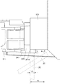
図1は本発明の一実施の形態である遊技機を示す斜視図、図2は図1に示した遊技機の正面図、図3は本実施の形態1に係る遊技盤を示す正面図、図4は図3に示した遊技盤を示す斜視図、図5は本実施の形態1に係る取付係合部、上下方向規制部および左右方向規制部を説明する図、図6は本実施の形態1に係る取付係合部の取付状態を説明する図、図7は本実施の形態1に係る取付係合部、上下方向規制部、左右方向規制部および段部を説明する図、図8は本実施の形態1に係る取付部を示す斜視図、図9は図8に示した取付部を遊技盤に取り付けた状態を示す斜視図、図10は図9に示した取付部を示す上面図、図11は図9に示した取付部を示す側面図、図12は図9に示した取付部を示す側面図、図13は本実施の形態1に係る取付係合部を示す斜視図、図14は本実施の形態1に係る取付係合部の他の例を示す斜視図、図15は図13に示した取付係合部の正面を示す正面図、図16は図13に示した取付係合部の右側面を示す側面図、図17は図13に示した取付係合部の背面を示す背面図、図18は図13に示した取付係合部の上面を示す上面図、図19は図13に示した取付係合部の下面を示す下面図、図20は本実施の形態1に係る取付係合部の移動許容状態および移動規制状態を説明する図、図21は本実施の形態1に係る移動許容状態での取付係合部および遊技盤の取付構造を説明する図、図22は本実施の形態1に係る移動許容状態での取付係合部および遊技盤の取付構造を説明する図、図23は本実施の形態1に係る移動規制状態での取付係合部および遊技盤の取付構造を説明する図である。 1 is a perspective view showing a gaming machine according to one embodiment of the present invention, FIG. 2 is a front view of the gaming machine shown in FIG. 1, and FIG. 3 is a front view showing a gaming board according to the first embodiment, 4 is a perspective view showing the gaming board shown in FIG. 3, FIG. 5 is a diagram for explaining the mounting engagement portion, the vertical direction restricting portion, and the left and right restricting portion according to the first embodiment, and FIG. FIG. 7 is a view for explaining the attachment state of the attachment engaging portion according to the first embodiment, FIG. 7 is a view for explaining the attachment engaging portion, the vertical direction restricting portion, the left and right restricting portion, and the step portion according to the first embodiment. FIG. 9 is a perspective view showing a mounting portion according to the first embodiment, FIG. 9 is a perspective view showing a state where the mounting portion shown in FIG. 8 is attached to the game board, and FIG. 10 is an upper surface showing the mounting portion shown in FIG. FIG. 11, FIG. 11 is a side view showing the mounting portion shown in FIG. 9, FIG. 12 is a side view showing the mounting portion shown in FIG. 9, and FIG. FIG. 14 is a perspective view showing another example of the attachment engaging portion according to the first embodiment, FIG. 15 is a front view showing the front of the attachment engaging portion shown in FIG. 16 is a side view showing the right side surface of the attachment engagement portion shown in FIG. 13, FIG. 17 is a rear view showing the back surface of the attachment engagement portion shown in FIG. 13, and FIG. 18 is the attachment engagement shown in FIG. FIG. 19 is a bottom view showing the bottom surface of the mounting engagement portion shown in FIG. 13, and FIG. 20 shows the movement allowable state and the movement restriction state of the mounting engagement portion according to the first embodiment. FIG. 21 is a diagram for explaining the mounting structure of the mounting engagement portion and the game board in the movement-permitted state according to the first embodiment, and FIG. 22 is the mounting in the movement-permitted state according to the first embodiment. FIG. 23 is a view for explaining the attachment structure of the engagement portion and the game board, and FIG. 23 is a view showing the attachment engagement portion and the movement restriction state according to the first embodiment. It is a diagram illustrating a game board of the mounting structure.
図1および図2に示すように、パチンコ遊技機(遊技機)1は、遊技盤10(図3および図4参照)が装着される本体部2と、本体部2内で遊技盤10の背後に設けられる表示装置としての液晶表示装置(LCD)20(図5参照)と、この本体部2に取り付けられるガラス扉3、上皿部4、下皿部5、カバー6およびハンドル7とを備えている。
As shown in FIGS. 1 and 2, a pachinko gaming machine (game machine) 1 includes a
ガラス扉3および上皿部4は一体化して形成されており、この一体化された開閉扉(開閉体)は、その一端が本体部2に回動可能に軸支され、他端が本体部2に係合するようになっている。ガラス扉3は、可動可能に設けられた遊技盤10を視認可能に被うものである。
The
上皿部4はガラス扉3の下側に位置し、払い出された遊技球および遊技領域に打ち込まれる遊技球が貯留される上皿4aを有している。上皿部4の所定の位置に、遊技終了時などにおいて上皿4aに貯留された遊技球を後述する下皿5aに移動させて取り出す場合に操作されるシャッタレバー8が設けられている。
The
上皿部4の下側に位置する下皿部5は、本体部2に固定されており、払い出しにより上皿4aからオーバーフローした遊技球が貯留される下皿5aを有している。
The
下皿部5の右側に設けられたハンドル7は、外レール11aおよび内レール11b(図3および図4参照)を介して遊技盤10の遊技領域へ遊技球を打ち込む際に回動操作されるものであり、遊技球の発射を停止させるストップボタン(図示せず)が設けられている。
The
ガラス扉3の上側に位置するカバー6は本体部2に固定されており、カバー6の左右の部位6a,6bは、本体部2に設けられる左右のスピーカ(図示せず)にそれぞれ対応して、スピーカからの音声が聞こえるような構造になっている。
The
液晶表示装置(LCD)20は、演出画像(例えば、遊技状態に対応したアニメーションやその他の報知情報など。)等を表示可能な表示領域を備えている。 The liquid crystal display device (LCD) 20 includes a display area that can display effect images (for example, animation corresponding to a gaming state or other notification information).
遊技盤10は、図3および図4に示すように、外レール11aおよび内レール11bに包囲され、遊技球の流下が可能な遊技領域10aを有している。そして、その遊技領域10aには、多数の遊技くぎや風車などの障害物(図示せず)、一般入賞口12、通過ゲート13、可変入賞装置である大入賞口15、アウト口16、始動入賞口14,17を有する電動役物構成部材18からなる遊技部材が配置されている。
As shown in FIGS. 3 and 4, the
遊技盤10が透明である本実施の形態では、液晶表示装置20の表示領域が遊技盤10を通して視認可能に配置されている。また、液晶表示装置20にかえて、例えばプラズマディスプレイ等の表示手段を用いることもできる。
In the present embodiment in which the
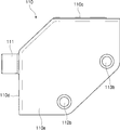
ここで、図3および図4に示すように四角形の遊技盤10には、その4ヶ所の隅部に、本体部2に設けられた4ヶ所の取付係合部と係合する取付部110,120、130,140が設けられている。
Here, as shown in FIG. 3 and FIG. 4, the
取付部110および取付部120には、遊技盤10の左側方(遊技盤10を表面から見て左側)に突出したピン部111およびピン部121が、一方、取付部130および取付部140には、遊技盤10の右側方(遊技盤10を表面から見て右側)に突出したピン部131およびピン部141が、それぞれ設けられている。これらの取付部の詳細については後述する。
The mounting
図5に示すように、本体部2には、遊技盤10を固定するための予め決められた4ヶ所の部位に、遊技盤10の取付部110,120、130,140のそれぞれと係合する取付係合部210,220,230,240が設けられている。なお、図5は、上記一体化された開閉扉(ガラス扉3および上皿部4)を開放(全開放)し、本体部2に対し液晶表示装置20を取り付けるとともに遊技盤10を取り外した状態を示している。
As shown in FIG. 5, the
取付係合部210は、図6および図13に示すように、ベース部300および可動規制部400を有している。ベース部300は、詳細については後述するが、本体部2の前方向から取付部110のピン部111を受け入れて、該ピン部111を所定の位置において前方向への動き(つまり遊技盤10の前方向への動き)を規制する機能を有している。可動規制部は、遊技盤10の上方向および前方向の動きを規制する機能を有している。
The
取付係合部220は、図7および図14に示すように、本体部2の前方向から取付部120のピン部121を受け入れて、該ピン部121を所定の位置において前方向への動き(つまり遊技盤10の前方向への動き)を規制する機能を果たすベース部300を有している。この取付係合部220は、取付係合部210のベース部300と同一である。
As shown in FIGS. 7 and 14, the
取付係合部230は、取付係合部210の構成(構造)と同様に、ベース部および可動規制部を有している。ベース部は、本体部2の前方向から取付部130のピン部131を受け入れて、該ピン部131を所定の位置において前方向への動き(つまり遊技盤10の前方向への動き)を規制する機能を有している。可動規制部は、遊技盤10の上方向および前方向の動きを規制する機能を有している。
Similar to the configuration (structure) of the mounting
取付係合部240は、取付係合部220の構成(構造)と同様に、本体部2の前方向から取付部140のピン部141を受け入れて、該ピン部141を所定の位置において前方向への動き(つまり遊技盤10の前方向への動き)を規制する機能を果たすベース部を有している。
Similar to the configuration (structure) of the mounting
なお、遊技盤10の下側に設けられる取付部120,140と係合する取付係合部220,240には、取付係合部210,230に設けられている可動規制部は設けられていない。
In addition, the movable engaging part provided in the attachment engaging part 210,230 is not provided in the attachment engaging part 220,240 engaged with the attachment part 120,140 provided on the lower side of the
再度、図5を参照して説明する。本体部2は、取付係合部210および取付係合部230は、それぞれ遊技盤10の上方向の動きを規制する上方向規制部(これについては後述する)を有している。
Again, a description will be given with reference to FIG. The
本体部2には、取付係合部220の固定位置と取付係合部240の固定位置との間であって、当該2つの固定位置間を結ぶ線分よりも下方の所定の位置に、遊技盤10の下方向の動きを規制する下方向規制部513,514と、がそれぞれ設けられている。
The
この実施の形態では、取付係合部210および取付係合部230の各上方向規制部と、下方向規制部513,514とで、遊技盤10の上下方向の動きを規制する上下方向規制部の機能を果たすようになっている。
In this embodiment, the upper and lower direction restricting portions that restrict the vertical movement of the
また、本体部2には、取付係合部210の固定位置と取付係合部220の固定位置との間の所定位置に、遊技盤10の左右方向の動きを規制する左右方向規制部515と、取付係合部230の固定位置と取付係合部240の固定位置との間の所定位置に、遊技盤10の左右方向の動きを規制する左右方向規制部516と、がそれぞれ設けられている。
The
下方向規制部513は、図7に示すように、コ字型の形状を有しており、このコ字型形状の平坦な部位の両側から突出している部位(凸部)513aの先端面が、遊技盤10の下端面と接するようになっている。しかも、下方向規制部513は、当該遊技盤10の下方向の動きを規制すべく本体部2の所定の位置に固着されている。下方向規制部514も、下方向規制部513と同様の構造および本体部2の所定の位置に固着されている。
As shown in FIG. 7, the downward
左右方向規制部515は、図7に示すように、遊技盤10の左側端面(遊技盤10を表面から見て左)と接する部位、遊技盤10の裏面と接する部位とが形成された切り欠き部515aを有している。左右方向規制部516は、図示していないが、遊技盤10の右側端面(遊技盤10を表面から見て右)と接する部位、遊技盤10の裏面と接する部位とが形成された切り欠き部を有している。
As shown in FIG. 7, the left-right
ところで、上述した上下方向規制部(取付係合部210,230および下方向規制部513,514)、および左右方向規制部515,516は、遊技盤10に取り付けられた各取付部110〜140のピン部111,121,131,141が、各取付係合部210,220,230,240の後述する前方向規制部により前方向への動きを規制された状態において、遊技盤10の上下方向あるいは左右方向の動きを規制するようになっている。
By the way, the above-described vertical direction restricting portions (
なお、液晶表示装置20は、図5〜図7に示すように、その上側は取付係合部210,230によって支持され、一方、その下側は本体部2に形成された下端支持段部(の上面517a),518によって支持されている。
As shown in FIGS. 5 to 7, the upper side of the liquid
次に、上述した遊技盤10に取り付けられる取付部110,120,130,140の構成(構造)について、図8〜図12を参照して説明する。
Next, the configuration (structure) of the
取付部110は、図8に示すように、遊技盤10の一方の面(例えば表面)に取り付けられる第1のブラケットと、遊技盤10の他方の面(例えば裏面)に取り付けられる第2のブラケットとが一体に形成されたブラケット1100と、一端部がネジ部112a,113aを有するとともに他端部はブラケット1100に圧接する圧接部112b、113bを有する軸部112、113と、を備えている。
As shown in FIG. 8, the mounting
この一体化されたブラケット1100は、図8および図9に示すように、遊技盤10の表面101に接する部位110a、裏面102に接する部位110b、上端面105に接する部位110c、および側端面106に接する部位110dが形成されている。
As shown in FIGS. 8 and 9, the
このようなブラケット1100においては、その部位110aに、軸部112,113が挿通される挿通孔114a,115aが形成されているとともに、その部位110bに、軸部112,113が挿通される挿通孔114b,115bが形成されている。
In such a
また、部位110bにおける挿通孔114b,115bに対応する部位には、図8および図10に示すように、軸部112,113のネジ部112a,113aに螺合する螺合部116a,116bが形成されている。
Further, as shown in FIGS. 8 and 10,
さらに、部位110cには、図9および図10に示すように、取付係合部(例えば取付係合部210)の可動規制部(例えば可動規制部400)と係合する係合部117と、前記可動規制部と圧接する圧接部118とが形成されている。ここでは、圧接部118の一部は係合部117を兼ねていることになる。
Furthermore, as shown in FIGS. 9 and 10, the
ところで、遊技盤10には、取付部110に対応して、図8に示すように、左上隅の所定の位置に、所定の距離離間して2つの貫通孔103a,103bが形成されているとともに、取付部110特にブラケット1100の部位110bを収容し、位置ズレを防止するブラケット収容凹部104が形成されている。ブラケット収容凹部104は、ブラケット1100の部位110bの少なくとも一部の部位と嵌合するような凹部の形状を有している。
By the way, in the
上述した構成の取付部110を、その開口部を介して遊技盤10の左上の隅の部位に装着し、その後、軸部112,113を、挿通孔114a,115a、遊技盤10の貫通孔103a、103bおよび挿通孔114b,115bを介して螺合部116a,116bに螺合する。これにより、取付部110は、図9、図11および図12に示すように遊技盤10に固定される。
The mounting
なお、図11は、遊技盤10の表面101側から見た取付部を示す側面図を示しており、図12は、遊技盤10の裏面102側から見た取付部を示す側面図を示している。
11 shows a side view showing the mounting portion viewed from the
このような取付部110においては、第1のブラケットおよび第2のブラケットが一体に形成されたブラケット1100を遊技盤10に装着し、上述したようにして軸部112,113のネジ部112a,113aを螺合部(ナット)116a,116bに螺合するだけで、取付部110の遊技盤10への取り付け作業を容易に実施することが可能になる。
In such an
取付部120,130,140は、取付部110の構成(構造)とは、基本的には同様であるものの、次の点で相違する。
The mounting
取付部120は、遊技盤10の左側方(遊技盤10を表面から見て左側)に突出したピン部121を有し、遊技盤10の表面、裏面、下端面および側端面の4つの面と接する一体化されたブラケットを有している。
The mounting
取付部130は、遊技盤10の右側方(遊技盤10を表面から見て右側)に突出したピン部131を有し、遊技盤10の表面、裏面、上端面および側端面の4つの面と接する一体化されたブラケットを有している。
The
取付部140には、遊技盤10の右側方(遊技盤10を表面から見て右側)に突出したピン部141を有し、遊技盤10の表面、裏面、下端面および側端面の4つの面と接する一体化されたブラケットを有している。
The mounting
そして、取付部120,130,140は、取付部110の場合と同様に、遊技盤10の表面側から軸部112,113に対応する2つの軸部のネジ部を螺合部(ナット)に螺合して、遊技盤10に取り付けるようになっている。
Then, as in the case of the mounting
次に、取付係合部210の構成(構造)について、図13〜図19を参照して詳細に説明する。
Next, the configuration (structure) of the mounting
取付係合部210は、上述したようにベース部300および可動規制部400を備えている。
The mounting
ベース部300は、図13および図14に示すように、本体部2の前方向から取付部110のピン部111を受け入れ、該ピン部111を下方向の支持位置(凹部)311へ案内する案内溝310と、支持位置(凹部)311においてピン部111の前方向への動きを規制する前方向規制部320と、可動規制部400を摺動可能に支持する軸部330とを有している。
As shown in FIGS. 13 and 14, the
また、図14に示すように、ベース部300の部位340には、ネジなどの固定部材によってベース部300を本体部2に固定するための孔340a,340bが形成されている。
Further, as shown in FIG. 14, holes 340 a and 340 b for fixing the
ここで、図13の取付係合部210の正面図を図15に示し、当該取付係合部210の右側面図を図16に示し、当該取付係合部210の背面図を図17に示し、当該取付係合部210の上面図を図18に示し、当該取付係合部210の下面図を図19に示す。
Here, a front view of the mounting
可動規制部400は、上述した上方向規制部の機能を果たすものである。この上方向規制部つまり可動規制部400は、図13および図20に示すように、遊技盤10の動きを許容する移動許容位置P1と、遊技盤10の上方向の動きを規制する移動規制位置P2との間で移動可能になっている。
The movable restricting
この可動規制部400は、図13に示すように取付係合部210(のベース部300の軸部330)に揺動可能に取り付けられ、また移動規制位置P2において、図23に示すように遊技盤10のブラケット1100に形成されている圧接部118(図9参照)に接するようになっている。
The movable restricting
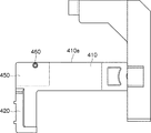
また、可動規制部400は、図13、図15および図23に示すように、移動規制位置P2において遊技盤10の前面つまり表面101(図9参照)と接する部位(側面)420aを有するストッパ部420を備えている。
Further, as shown in FIGS. 13, 15, and 23, the movable restricting
このストッパ部420は、図23に示すように、実際には遊技盤10そのものではなく、遊技盤10に取り付けられている取付部、例えば取付部110のブラケット1100(の部位110a)に接するようになっている。そのため、遊技盤10に傷等を生じさせることなく、遊技盤10の前方向への動きを規制することが可能となる。
As shown in FIG. 23, the
可動規制部400は、図20に示すように、軸部330に揺動可能に支持されている支持部410が、移動許容位置P1と移動規制位置P2との間で移動されるようになっている。
As shown in FIG. 20, the movable restricting
この実施の形態では、支持部410の側面410aが、移動許容位置P1に位置したときは、例えば取付係合部210は移動許容状態であると定義し、一方、移動規制位置P2に位置するときは、例えば取付係合部210は移動規制状態であると定義する。
In this embodiment, when the
ちなみに、図20および図21において、実線で示す可動規制部400の状態では例えば取付係合部210は移動許容状態になっており、一方、点線で示す可動規制部400では例えば取付係合部210は移動規制状態になっている。
20 and 21, for example, in the state of the movable restricting
なお、図21は、図20において移動許容状態の取付係合部を正面から見た状態、つまり遊技盤10のピン部111を案内溝320に案内(挿入)する方向から見た状態を示している。
FIG. 21 shows a state in which the attachment engaging portion in the movement allowed state in FIG. 20 is seen from the front, that is, a state seen from the direction in which the
移動許容状態の場合、すなわち支持部410の側面410aが移動許容位置P1に位置する場合は、遊技盤10の動きが許容され、取付係合部210に取り付けられた遊技盤10を取り外したり、遊技盤10を取付係合部210に取り付けることができる。
In the movement-permitted state, that is, when the
これに対し移動規制状態の場合、すなわち支持部410の側面410aが移動規制位置P2に位置する場合は、遊技盤10は取付係合部210に固定され、上下方向規制部(取付係合部210,230の可動規制部400および下方向規制部513,514)によって、上下方向の動きが規制されることになる。
On the other hand, in the movement restricted state, that is, when the
ところで、支持部410の側面410aが移動許容位置P1に位置していたとしても、図13および図21に示すように、支持部410に切り欠き部421が形成されているので、取付部110のピン部111を案内溝310に挿入することが可能であり、遊技盤10の本体部2に対する取り付や取り外しの際には、何ら支障はない。
By the way, even if the
可動規制部400においては、図13および図20に示すように、操作者が可動規制部400を摺動させる摺動操作のときにその操作がし易いように、支持部410に凹部431,432が設けられているとともに、ストッパ部420に凹部433および凸部434が設けられている。
In the movable restricting
支持部410は、図13、図16および図23に示すように、遊技盤10に設けられた取付部110の圧接部118(図9および図10参照)に圧接する圧接部450と、この圧接部450の一部の領域に設けられ、取付部110の係合部117(図10参照)と係合する突起部(凸部)460とを有している。
As shown in FIGS. 13, 16, and 23, the
上述した取付係合部210以外の取付係合部の構造について説明すると、取付係合部230は取付係合部210と同様の機能を果たす構造になっている。また、取付係合部220は取付係合部210のベース部300と同様の構造になっている。さらに、取付係合部240は取付係合部210のベース部300と同様の機能を果たす構造になっている。
The structure of the mounting engagement portion other than the above-described mounting
以上説明した構成において、遊技盤10を本体部2に取り付ける場合の操作およびその取付構造について、図20〜図23を参照して説明する。
In the configuration described above, an operation and a mounting structure for mounting the
例えば、遊技機1を製作する作業者、遊技機1(の遊技盤10)をメンテナンスする作業者などの作業者は、取付部110,120,130,140が設けられた遊技盤10を、本体部2の取付係合部210,220,230,240へ係合させるときは、まず、取付係合部210の可動規制部400が移動許容位置P1に位置するようにする。
For example, an operator such as an operator who manufactures the
例えば、本体部2に取り付けられている遊技盤10をメンテナンスする場合には、移動規制状態にある取付係合部210の可動規制部400を、図20に示すように、移動許容状態つまり移動許容位置P1に位置するように揺動させる。このとき、作業者は、支持部410の凹部431,432、およびストッパ部420の凹部433、凸部434のうち、1つ以上の部位を手で支持して揺動操作することにより、可動規制部400の揺動操作がし易くなる。取付係合部230についても、これと同様な操作が行われる。
For example, when the
このようにして可動規制部400が移動許容位置P1に達したときは、図21に示すように可動規制部400の支持部410に切り欠き部421が形成されているので、遊技盤10のピン部111を、ベース部300の案内溝310に挿入することが可能となる。
When the movable restricting
そこで作業者は両手で遊技盤10を持って、遊技盤10の取付部110,120,130,140のピン部111、121,131,141を、取付係合部210,220,230,240のベース部の案内溝に挿入して、所定の支持位置である凹部に収容させる。
Therefore, the operator holds the
例えば、図22に示すように取付部110のピン部111を、これが案内溝310に案内されるように、案内溝310に挿入する(図中点線矢印で示される方向に挿入する)。この図22に示す例では、説明の都合上、可動規制部400は省略されている。
For example, as shown in FIG. 22, the
このようにして遊技盤10の各取付部の各ピン部が各取付係合部の各凹部に収容された場合は、遊技盤10の仮固定が終了したことになる。
Thus, when each pin part of each attachment part of the
このように遊技盤10の仮固定が終了したときは、遊技盤10の各取付部の各ピン部が各取付係合部の各凹部に収容され、しかも前方向規制部によって遊技盤10が前方向への動きが規制されているので、遊技盤10は前方向へ移動(倒れる)ことはない。
When the
そのため、遊技盤10の仮固定を終了した場合には、作業者は遊技盤10を抑えていた両手を離して、次の作業に移行することが可能になる。
Therefore, when the temporary fixing of the
すなわち、作業者は、移動許容位置P1に位置する取付係合部210,230の可動規制部を、移動許容位置P1から移動規制位置P2へ移動させるべく摺動操作を行う。
That is, the operator performs a sliding operation to move the movable restricting portions of the
すると、例えば取付係合部210においては、可動規制部400の圧接部450(の底面)が、遊技盤10に設けられた取付部110のブラケット1100に形成されている圧接部118に圧接する。
Then, for example, in the
これにより、遊技盤10は、上方向規制部(つまり取付係合部210,230の可動規制部400)、および下方向規制部513,514によって上下方向の動きが規制されることになる。
Thus, the vertical movement of the
また、移動規制状態にある例えば取付係合部210においては、可動規制部400のストッパ部420の部位(側面)420aに、ブラケット1100(部位110a)が接するとともに、可動規制部400の突起部(凸部)460と、取付部110のブラケット1100に形成されている係合部117とが係合する。
For example, in the mounting
これにより、遊技盤10は、ベース部300の前方向規制部320による前方向への動きの規制に加えて、より一層、前方向への動きが規制される。
Thereby, in addition to the restriction | limiting of the movement to the front by the front
さらに、上述したように、上方向規制部つまり取付係合部210,230の可動規制部400および下方向規制部513,514、換言すれば上下方向規制部によって上下方向の動きが規制されているときは、左右方向規制部515,516によって左右方向の動きが規制されていることになる。
Further, as described above, the movement in the vertical direction is restricted by the upper restriction part, that is, the
このように遊技盤10は、上下方向、左右方向および前方向の動きが規制されるので、本体部2(の各取付係合部)に確実に固定されることとなる。これで、遊技盤10の本固定が終了したことになる。
As described above, since the
上述したように、作業者は、遊技盤10の各取付部の各ピン部を、本体部2の各取付係合部の各ベース部の案内溝に案内させ、かつ凹部に収容させて、その後、上側の2つの取付係合部の可動規制部を、移動許容位置P1から移動規制位置P2へ移動させるべく摺動操作を実施することにより、遊技盤10の仮固定から本固定までの取付作業を、一連の作業で実施することが可能になる。
As described above, the worker guides each pin portion of each attachment portion of the
以上説明したように、本実施の形態1によれば、次の(1)〜(5)の作用効果を期待することができる。 As described above, according to the first embodiment, the following effects (1) to (5) can be expected.
(1)遊技盤10の取付部110〜140を本体部2の取付係合部210〜240へ係合させるに際し、遊技盤10の側方に突出したピン部111、121,131,141を本体部2の各取付係合部の案内溝310を介して前方向規制部320へ移動させるようにしているので、遊技盤10のピン部を本体部2の前方向規制部320へ移動させた時点で当該遊技盤10は仮固定された状態となり、このため、遊技盤を固定する前であっても当該遊技盤は前方向へ倒れることはなく、遊技盤取付の作業性を向上させることができる。
(1) When engaging the mounting
(2)取付部のピン部が前方向規制部320により前方向への動きを規制された状態において、上下方向規制部、すなわち上方向規制部(取付係合部210,230の可動規制部400)および下方向規制部513,514と、左右方向規制部515,516とによって、遊技盤10の前方向、上下方向および左右方向の動きが規制されるので、遊技盤の仮固定および本固定を安定にすることが可能になる。
(2) In a state where the pin portion of the attachment portion is restricted from moving forward by the
(3)上方向規制部つまり可動規制部400は、移動許容位置P1と移動規制位置P2との間で移動可能になっているので、作業者は遊技盤の仮固定から本固定への固定作業を容易に行うことが可能になる。
(3) Since the upward restricting portion, that is, the movable restricting
(4)案内溝310および前方向規制部320を有する取付係合部210,230に揺動可能に取り付けられた可動規制部400を、移動許容位置P1から移動規制位置P2へ摺動させることで、取付部110,130のピン部111,131が案内溝310を介して前方向規制部320へ移動され仮固定の状態にある遊技盤10の動きを規制して、本固定するようにしているので、取付係合部および可動部材により遊技盤の仮固定から本固定までの固定操作を連続(一括)して行うことができる。これにより、遊技盤の仮固定から本固定まで実施するための構造を簡易な構造で実現することができる。
(4) By sliding the movable restricting
(5)移動規制位置P2に存在する遊技盤10は、可動規制部400(上方向規制部)および下方向規制部513,514によって上下方向の動きが規制されるのに加えて、ストッパ部420によって前方向の動きが規制されるので、遊技盤の強固な本固定を確実に行うことが可能になる。
(5) The
(実施の形態2) (Embodiment 2)
次に、本発明の実施の形態2に係る遊技機について添付図面を参照して説明する。
Next, a gaming machine according to
この実施の形態2に係る遊技機は、基本的には、上述した実施の形態1に係る遊技機の構造(構成)および機能を有している。ここでは、実施の形態1との相違点のみについて説明する。 The gaming machine according to the second embodiment basically has the structure (configuration) and function of the gaming machine according to the first embodiment described above. Here, only differences from the first embodiment will be described.
なお、実施の形態1では遊技盤の取り付け(取付構造)に着目して説明したのに対し、この実施の形態2では表示装置の取り付け(取付構造)に着目して説明する。 In the first embodiment, the description has been given focusing on the mounting (attachment structure) of the game board, while in the second embodiment, the description will be given focusing on the attachment (attachment structure) of the display device.
図24は図1に示した遊技機を表面側から見た分解斜視図、図25は図1に示した遊技機を背面側から見た分解斜視図、図26は表示装置を説明する正面図、図27は遊技機の制御系を示すブロック図、図28は実施の形態2に係る制御系ケースの分解斜視図、図29は実施の形態2に係る制御系ユニットの外観図、図30は実施の形態2に係る制御系ケース(制御系ユニットを外側ケースで覆った状態)の外観図、図31は実施の形態2に係る演出制御基板ユニットの分解斜視図、図32は本体の内部の一例を示す正面図、図33は本体に設けられた上方向移動規制段部近傍を示す斜視図、図34は本体に設けられた下端支持段部近傍を示す斜視図、図35は本体に設けられた他の下端支持段部近傍を示す斜視図、図36は表示装置の上端の支持および上方向の移動の規制を説明する斜視図、図37は図33に示す例において表示装置が取り付けられた状態を示す斜視図、図38は図34に示す例において表示装置が取り付けられた状態を示す斜視図、図39は図35に示す例において表示装置が取り付けられた状態を示す斜視図、図40はインバータ基板を保護するカバーケースがインバータ基板収容凹部に収容された状態を示す正面図、図41はインバータ基板を保護するカバーケースがインバータ基板収容凹部に収容された状態を示す斜視図、図42は表示装置の仮固定を説明する図、図43は表示装置の仮固定を説明する図、図44は表示装置と遊技盤との配置関係を説明する斜視図である。 24 is an exploded perspective view of the gaming machine shown in FIG. 1 viewed from the front side, FIG. 25 is an exploded perspective view of the gaming machine shown in FIG. 1 viewed from the back side, and FIG. 26 is a front view for explaining the display device. 27 is a block diagram showing the control system of the gaming machine, FIG. 28 is an exploded perspective view of the control system case according to the second embodiment, FIG. 29 is an external view of the control system unit according to the second embodiment, and FIG. FIG. 31 is an exploded perspective view of an effect control board unit according to the second embodiment, and FIG. 32 is an internal view of the main body of the control system case according to the second embodiment (a state in which the control system unit is covered with the outer case). 33 is a front view showing an example, FIG. 33 is a perspective view showing the vicinity of an upward movement restricting step provided on the main body, FIG. 34 is a perspective view showing the vicinity of a lower end supporting step provided on the main body, and FIG. 35 is provided on the main body. FIG. 36 is a perspective view showing the vicinity of the other lower end supporting step portion, and FIG. 36 shows the upper end of the display device. FIG. 37 is a perspective view showing a state where the display device is attached in the example shown in FIG. 33, and FIG. 38 is a perspective view showing the state where the display device is attached in the example shown in FIG. FIG. 39 is a perspective view showing a state in which the display device is attached in the example shown in FIG. 35, and FIG. 40 is a front view showing a state in which the cover case for protecting the inverter board is housed in the inverter board housing recess. 41, FIG. 41 is a perspective view showing a state in which a cover case for protecting the inverter board is housed in the inverter board housing recess, FIG. 42 is a diagram for explaining temporary fixing of the display device, and FIG. 43 is for explaining temporary fixing of the display device. FIG. 44 is a perspective view for explaining the positional relationship between the display device and the game board.
図24は図1に示したパチンコ遊技機1を前面側から見た分解斜視図を示し、図25は図1に示したパチンコ遊技機1を背面側から見た分解斜視図を示している。なお、図24および図25において、図1に示した構成要素と同様の機能を果たす部分には同一の符号を付している。
24 shows an exploded perspective view of the
さて、図24および図25において、パチンコ遊技機1は、本体部2、図3および図4に示した遊技盤10、表示装置としての液晶表示装置20、開閉扉30、および制御系ケース70を有している。
24 and 25, the
本体部2は、木枠2aと、この木枠2aに回動可能に支持される本体200とを有している。この本体部2(実際には本体200)は、遊技盤10および液晶表示装置20を収容する凹部500が形成されている。また、本体200(実際には凹部500の底部)には、後述する液晶表示装置20に設けられているインバータ基板を収容する凹部(以下、インバータ基板収容凹部という)520が形成されている。
The
遊技盤10は、遊技領域10a(図3)を含む領域が透光性部材で形成され、該透光性部材を介して液晶表示装置20を視認可能に本体200に対し当該本体200の表面側から取り付けられる。透光性部材は、例えばアクリル樹脂等の透明な樹脂で形成されている。
The
このような遊技盤10においては、液晶表示装置20に表示される画像を明確に視認することが可能なように、透光性部材の透明な箇所の可視光線透過率は30%以上であることが望ましく、50%以上であることがより望ましい。
In such a
この実施の形態2では、遊技領域10a(図3)を含む領域、すなわち遊技盤10全体を透光性部材で形成するようにしているが、本発明はこれに限定されることなく、遊技盤10の少なくとも一部、例えば遊技領域10aの全体または一部が透光性部材で形成されていれば良い。
In the second embodiment, the area including the
本実施の形態2に係る液晶表示装置20は、その裏面(背面)に液晶表示装置20を照明するための冷陰極管のインバータであるインバータ基板を備え、図24に示すように本体部2(の本体200)に対しその表面側から取り付けられる。つまり、液晶表示装置20は、遊技盤10の背後に位置するように本体200に表面側から取り付けられる。なお、液晶表示装置20の裏面には、図25に示すように、このインバータ基板を保護すべく、カバーケース21が取り付けられている。
The liquid
このような液晶表示装置20は、図26に示すように、表示領域20aと、後述する本体200に設けられているボス541,542,543,544(図32参照)に固定される、例えばビス止めされる固定部22,23,24,25とを有している。
As shown in FIG. 26, such a liquid
開閉扉30は、ガラス扉3および上皿部4から構成され、本体200に回動可能に支持される。
The opening / closing
制御系ケース70は、液晶表示装置20の表示を制御する表示制御基板(これについての詳細は後述する)を有しており、本体部2(の本体200)に対し当該本体200の背面側から取り付けられる。
The
次に、このような遊技機の制御系について、図27を参照して説明する。 Next, a control system of such a gaming machine will be described with reference to FIG.
パチンコ遊技機1の制御系は、主制御回路50と、この主制御回路50に接続される演出制御回路60、払出制御回路41および発射制御回路42を有している。
The control system of the
この制御系は主制御回路50を主な構成要素とし、制御系ユニット71に搭載されている。
This control system includes the
また、パチンコ遊技機1の払出制御回路41には、カードユニット43が接続されている。
A
このカードユニット43は、パチンコ遊技機1の近傍に設置され、プリペイドカードを差込可能な差込口を有しており、当該差込口に差し込まれたプリペイドカードに記録された記録情報を読み取る読み取り手段と、球貸し操作パネル46の操作に応じて、払出制御回路41に対し遊技球の貸出を指令する貸出指令信号を出力する貸出指令信号出力手段と、前述の読み取り手段によって読み取った記録情報から特定される貸出可能数から、貸出指令信号出力手段により貸出を指令した貸出数を減算し、上記差込口に差し込まれているプリペイドカードに当該情報を記録させる書き込み手段を有している。
This
主制御回路50には、予め設定されたプログラムに従ってパチンコ遊技機1の遊技動作を行うメインCPU(超小型演算処理装置)51、異常時や電源投入時に各種設定を初期値に戻すためのリセット信号を生成する初期リセット回路54、メインCPU51が動作する上で必要な各種データを記憶するメインRAM53、メインCPU51がパチンコ遊技機1の遊技動作を処理制御するためのプログラム、乱数抽選によって大当り判定をする際に参照される大当り判定テーブル、乱数抽選によって普通当り判定をする際に参照される普通当り判定テーブル、演出を抽選する際に参照される各種確率テーブルを格納しているメインROM52が実装されている。
The
また、メインRAM53は、メインCPU51によって計数された入賞記憶の数(通過ゲート13への入賞球数)を記憶するための入賞記憶カウンタ、およびメインCPU51によって計数された通過記憶の数(通過ゲートの通過球数)を記憶するための通過記憶カウンタを具備する。
The
ここで、メインCPU51は、始動入賞口14,17へ遊技球が入賞して始動入賞が発生すると大当り判定を行う大当り判定処理を行い、当該大当り判定結果に基づいて、特別図柄の変動表示を実行させるための変動表示パターンを決定する変動表示パターン決定手段である。
Here, the
具体的には、メインCPU51は、始動入賞が発生すると、所定の始動条件が成立したとして、大当り判定の結果に基づき、特別図柄の変動表示を実行させるための変動表示パターンを指示する変動表示パターンコマンド、変動表示の停止図柄を指示するコマンドを生成し、セットする。さらに、メインCPU51は、普通図柄表示装置に表示される内容の決定処理などを行っている。
Specifically, when the start winning is generated, the
また、メインCPU51は、所定の始動条件が成立したとき(例えば、始動入賞が発生した場合など)、変動表示パターンコマンドを生成し、セットする。
Further, the
さらにメインCPU51は、遊技状態が特定遊技状態に移行されると、大入賞口15の扉を開閉するように大入賞口SOL37を制御する大入賞口SOL制御手段を構成している。
Further, the
主制御回路50のI/Oポート55には、通過ゲート13の内側に設けられ、遊技球が通過するのを検知するセンサである通過ゲートSW34、始動入賞口14,17に入賞した遊技球を検知するセンサである始動口SW35が接続されている。また、大入賞口15内の継続入賞口に設けられ、入賞した遊技球を検知するセンサであるV・カウントSW31、大入賞口15内の普通入賞口に設けられ、入賞した遊技球を検知するセンサであるカウントSW32、一般入賞口12へ入賞した遊技球を検知するセンサである一般入賞口SW33、メインRAM53に記憶されている各種データを消去するためのバックアップクリアSW39が接続されている。また、ハンドル7の操作によって発射装置45から発射される遊技球を検知する発射球センサ(図示せず)、および発射されたものの遊技盤10の盤面まで到達せずに外レール11aおよび内レール11bに戻ってきた遊技球を検知する戻り球センサ(図示せず)が接続されている。さらに、このI/Oポート55には、アクチュエータとして、始動入賞口17を、遊技球を受け入れ易い状態と遊技球を受け入れ難い状態との間で切換える始動口SOL(ソレノイド)36、大入賞口15の扉を開閉する大入賞口SOL(ソレノイド)37、大入賞口15内のシーソを駆動するシーソSOL(ソレノイド)38等が接続されている。
The I /
上記各センサが遊技球を検知すると、その検知信号は主制御回路50のメインCPU51に入力され、メインCPU51は入力される検知信号に応じて、上記各アクチュエータ36、37、38をそれぞれ駆動制御する。また、演出制御回路60や払出制御回路41、発射制御回路42に対して、それぞれ主制御回路50のコマンド出力ポート56から制御指令が送信され、演出制御回路60や払出制御回路41、発射制御回路42によって液晶表示装置20や、スピーカ47、ランプ・LED48、払出装置44、発射装置45などの動作が制御される。
When each of the sensors detects a game ball, the detection signal is input to the
払出制御回路41には賞球や貸球等を払出す払出装置44が接続され、発射制御回路42には遊技球を遊技領域10aに向けて発射する発射装置45が接続されている。払出制御回路41は、一般入賞口12および始動入賞口14などに遊技球が入球したことを条件として主制御回路50から出力される払出指令信号に応じて払出装置44を駆動制御し、所定数の遊技球を賞球として払出させる。さらに、払出制御回路41は、カードユニット43から出力される貸出指令信号に応じて払出装置44を駆動制御し、所定数の遊技球を貸球として払出させる。また、発射制御回路42は、ハンドル7の回動操作に応じて発射ソレノイドを駆動制御する。これによって発射装置45から遊技球を発射させる。
The
また、ハンドル7には遊技球の発射を停止するストップボタン(図示せず)が設けられている。
The
演出制御回路60には、サブCPU61、プログラムROM62、およびワークRAM63が実装されている。
In the
サブCPU61は、コマンド入出力ポート64を介して主制御回路50から受信したコマンドを解釈し、その解釈結果に従って画像制御回路65、音声制御回路66、ランプ制御回路67等の制御を行う。
The
例えば、サブCPU61は、コマンド入出力ポート64を介して主制御回路50からの変動表示パターンコマンドを受信したときは、この受信した変動表示パターンコマンドに対応する制御データをセットする。そして、サブCPU61は、セットした制御データに含まれる演出パターンに従った演出画像の表示を行わせるように、画像制御回路65に指示するためのデータを経時的に変化させる。
For example, when the
プログラムROM62には、サブCPU61が、主制御回路50から出力される各種コマンドに基づいて画像制御回路65を処理制御するための制御プログラム、音声制御回路66を処理制御するための制御プログラム、およびランプ制御回路67を処理制御するための制御プログラムなどが格納されている。
In the
ワークRAM63は、サブCPU61が上記制御プログラムに従って処理制御を行う際の一時的な記憶手段となる。
The
画像制御回路65は、サブCPU61からの制御に応じて、液晶表示装置20に特別図柄の変動表示などの表示を実行するものであり、各種画像データを記憶する画像データROM(図示せず)と、サブCPU61からの制御に基づいて、画像データROMに記憶されている画像データを用いて、特別図柄の変動表示などの表示を実行するためのデータを生成する図示しないVDP(Video Display Processor)と、VDPにより生成された表示画像データをアナログ信号に変換するD/A変換回路(図示せず)とを具備する。
The
例えば、画像制御回路65は、サブCPU61の制御に基づいて、液晶表示装置20に対し、大当り判定の結果に対応する特別図柄および演出画像を変動表示させるなどの画像表示制御処理を行う。また、画像制御回路65および液晶表示装置20は、特別図柄の変動表示時の演出表示態様によって当該遊技におけるリーチ演出発生の有無または発生するリーチ演出の種類または大当り発生の信頼度を報知する報知手段を構成している。
For example, the
このように、画像制御回路65が所定時間ごとに送信されるサブCPU61の指示内容を実行することにより、液晶表示装置20においては、例えば、変動表示パターンに対応する特別図柄や演出画像が表示される。
As described above, when the
音声制御回路66には本体200の上部の左右に設けられる2つのスピーカ47が接続されている。音声制御回路66は、サブCPU61の制御に基づき、音信号を生成する。2つのスピーカ47は、入力したこの音信号に基づいて音を発生する。
Two
ランプ制御回路67には報知装置であるランプ・LED48が接続されている。ランプ制御回路67は、サブCPU61の制御に基づき、信号を生成する。ランプ・LED48は、入力したこの信号に基づいてパチンコ遊技機1の各所に備え付けられているランプやLEDなどの点灯表示等を行う。
The
なお、パチンコ遊技機1における各処理は、主制御回路50と演出制御回路60とにより制御されているが、主制御回路50は、演出制御回路60により制御される処理の全部または一部を処理してもよく、演出制御回路60は、主制御回路50により制御される処理の全部または一部を処理してもよい。
Each process in the
ところで、この実施の形態2においては、演出制御回路60が、液晶表示装置20の表示を制御する表示制御手段(表示制御基板)の機能を果たす。しかし、演出制御回路60は主制御回路50の指示の下で液晶表示装置20を制御するので、実際には、主制御回路50と演出制御回路60とが協働して、表示制御手段(表示制御基板)の機能を果たすことになる。
By the way, in the second embodiment, the
次に、このような制御系を構成する基板等を有する制御系ケース70の詳細について、図28〜図31を参照して説明する。
Next, details of the
図28は実施の形態2に係る制御系ケースの分解斜視図であり、図29は実施の形態2に係る制御系ユニットの外観図であり、図30は実施の形態2に係る制御系ケース(制御系ユニットを外側ケースで覆った状態)の外観図であり、図31は実施の形態2に係る演出制御基板ユニットの分解斜視図である。 FIG. 28 is an exploded perspective view of the control system case according to the second embodiment, FIG. 29 is an external view of the control system unit according to the second embodiment, and FIG. 30 is a control system case according to the second embodiment ( FIG. 31 is an exploded perspective view of an effect control board unit according to the second embodiment.
図28に示すように、制御系ケース70は、制御系ユニット71と、この制御系ユニット71を被う外側ケース72とを有している。
As shown in FIG. 28, the
制御系ユニット71は、図28および図29に示すように、主制御回路50を構成する主制御基板ユニット710、ランプ制御回路67を除いた演出制御回路60を構成する演出制御基板ユニット720、各電子部品が動作するために必要な電圧の電源(例えば24V、12V、5Vなど)を生成する電源基板ユニット730、発射制御回路42を構成する発射制御基板ユニット740、払出制御回路41を構成する払出制御基板ユニット750、カードユニット43における読み取り手段、貸出指令信号出力手段および書き込み手段を構成するCR中継基板ユニット760、ランプ制御回路67を構成するランプ制御基板ユニット(図示せず)などを有している。
28 and 29, the
図28において、制御系ユニット71に対しその各ユニットを保護するように外側ケース72を取り付け、この外側ケース72側から見た制御系ケース70の様子を、図30に示す。
28, the
このような制御系ケース70においては、制御系ユニット71が本体200の背面側と対向するように、この本体200に取り付けられる。
In such a
演出制御基板ユニット720は、図31に示すように、演出制御基板721と基板上部ケース722と基板下部ケース723とを備えている。
As shown in FIG. 31, the effect
演出制御基板721の表面部721aには、サブCPU61等を備える演出制御回路60が実装されている。
An
また、その表面部721aには、電子部品(例えば、プログラムROM62)が内蔵されたROMカートリッジ(ケース体)724が、コネクタ部(図示せず)を介して着脱可能に取り付けられている。なお、ROMカートリッジ724には、プログラムROM62以外の電子部品が内蔵されていてもよい。例えば、ワークRAM63が内蔵されていてもよい。
A ROM cartridge (case body) 724 in which an electronic component (for example, program ROM 62) is built is detachably attached to the
ROMカートリッジ724は、所定の画像を含む演出に関する情報を記憶するものであり、遊技機の機種に応じた演出に関する情報を記憶する。
The
この実施の形態2においては、所定の画像には、遊技盤に施されるべき例えば模様や文字に対応する画像、普通図柄画像、特別図柄表示画像、および演出画像が含まれる。また、演出に関する情報には、上記所定の画像、画像制御回路65を処理制御するための制御プログラム、音声制御回路66を処理制御するための制御プログラム、およびランプ制御回路67を処理制御するための制御プログラムが含まれる。
In the second embodiment, the predetermined image includes, for example, an image corresponding to a pattern or characters, a normal symbol image, a special symbol display image, and an effect image to be applied to the game board. Further, the information related to the production includes the predetermined image, a control program for controlling the processing of the
上述したROMカートリッジ724は、遊技機の機種に応じて演出内容が異なる場合には、上述した所定の画像を含む演出に関する情報が異なっているので、当該遊技機の機種の数に応じた数だけ用意される。そして、遊技機の機種に対応するROMカートリッジ724が演出制御基板ユニット720に搭載(装着)される。
In the
例えば、遊技盤10が同一であっても、演出画像または効果音の相違によって、遊技機の機種も異なってくるので、それぞれの機種に対応したROMカートリッジ724が演出制御基板ユニット720に装着される。
For example, even if the
また、遊技盤10に施されるべき例えば模様や文字を変更したい場合は、遊技盤10に施されるべき所望の模様や文字に対応する画像データを記憶したROMカートリッジ724が演出制御基板ユニット720に装着される。
In addition, when it is desired to change, for example, a pattern or a character to be applied to the
基板上部ケース722は、図31に示すように、規制ケース725と一体的に形成されている。規制ケース725は、基板上部ケース722の表面部722aから、演出制御基板721とは反対方向に突出して設けられている。そして、当該規制ケース725は、ROMカートリッジ724を覆うとともに当該ROMカートリッジ724の移動を規制する。
As shown in FIG. 31, the substrate
ここで、基板上部ケース722は、基板上部ケース722の4箇所の隅部が、それぞれ演出制御基板721の表面部721aの4箇所の隅部に形成された孔を介して、基板下部ケース723の4箇所の隅部に例えばネジ等で固定されて取り付けられるようになっている。
Here, the board
これにより、ROMカートリッジ724等が取り付けられた演出制御基板721は基板下部ケース723に固定される。また、基板上部ケース722は、ROMカートリッジ724等が取り付けられた演出制御基板721の表面部721aを覆っている。
As a result, the
このような演出制御基板ユニット720の基板上部ケース722が、制御系ユニット71の外側ケース72と対向するように、演出制御基板ユニット720の基板下部ケース723の底面723aが制御系ユニット71に取り付けられる(例えばネジ止めされる)。
The
そして、各ユニット710〜760が制御系ユニット71に取り付けられる(例えばネジ止めされる)と、この制御系ユニット71は、その底面71a(図28参照)が本体200の背面側と対向するように、この本体200の所定の部位に取り付けられる(例えばネジ止めされる)。
When each of the
最後に、本体200に取り付けられた制御系ユニット71に対し、各ユニット710〜750を覆うように、外側ケース72が取り付けられる(例えばネジ止めされる)。
Finally, the
ところで、上述したようにこの実施の形態2においては、演出制御基板ユニット720が、液晶表示装置20の表示を制御する表示制御手段(表示制御基板)の機能を果たす。しかし、演出制御基板ユニット720は主制御基板ユニット710の指示の下で液晶表示装置20を制御するので、実際には、主制御基板ユニット710と演出制御基板ユニット720とが協働して、表示制御手段(表示制御基板)の機能を果たすことになる。
Incidentally, as described above, in the second embodiment, the effect
ここで、演出内容の変更に伴う遊技機の機種変更は、次の(1)〜(4)の操作手順に従って行われる。 Here, the model change of the gaming machine accompanying the change of the production content is performed according to the following operation procedures (1) to (4).
(1)例えば、図1に示したパチンコ遊技機1の状態において機種変更を実施する場合は、木枠2aに回動可能に支持されている本体200(図24および図25参照)を開放する。
(1) For example, when the model change is performed in the state of the
(2)制御系ケース70の外側ケース72を取り外し、さらに、演出制御基板ユニット720の基板上部ケース722を取り外す。
(2) The
(3)演出制御基板721に装着されているROMカートリッジ724を取り外し、この旧演出内容に対応するROMカートリッジ724に代替して、新たな演出内容に対応するROMカートリッジ724を演出制御基板721に装着する。
(3) The
(4)演出制御基板ユニット720の基板上部ケース722を取り付け、次に制御系ケース70の外側ケース72を取り付け、最後に本体200を閉じる。
(4) The board
以上説明したように、演出内容の変更による遊技機の機種の変更は、新たなROMカートリッジと、旧ROMカートリッジとを交換することにより実現することができる。 As described above, the change of the model of the gaming machine due to the change of the production contents can be realized by exchanging a new ROM cartridge and an old ROM cartridge.
以上説明したように本実施の形態2では、本体200に対し、当該本体200の表面側から液晶表示装置20を取り付けるとともに、更に当該本体200の表面側から遊技盤10を取り付け(つまり遊技盤10の背後に液晶表示装置20が位置する)、かつ本体200に対し、当該本体200の背面側から制御系ケース70を取り付けるようにしている。
As described above, in the second embodiment, the liquid
そのため、本実施の形態2では、本体200は、表示制御基板(実際には、表示制御基板を有する制御系ケース70)を挿通させる大きな開口部は有していない。したがって、本体200は、表示制御基板用の大きな開口部を有していないので、当該本体200の剛性は大きいものになっている。
Therefore, in the second embodiment, the
これに対し、従来の遊技機においては、本体200に対応する本体(ベースドア)に、表示装置が取り付けられた遊技盤の背面側に積載された表示制御基板を挿通させる開口部を設けていた。そのため、前記本体(ベースドア)は、表示制御基板用の大きな開口部を有するため、当該本体(ベースドア)の剛性は小さくなっていた。
On the other hand, in the conventional gaming machine, an opening through which a display control board loaded on the back side of the game board to which the display device is attached is provided in the main body (base door) corresponding to the
次に、本体200の構成について、図32〜図36を参照して説明する。
Next, the configuration of the
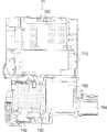
図32は、液晶表示装置20、遊技盤10および開閉扉30を取り付ける前の本体200を表面側から見た様子(正面図)を示している。この図31に示す例は、図5に示した例の構成において液晶表示装置20を削除した構成になっている。
FIG. 32 shows a state (front view) of the
また、図33〜図36は本実施の形態2に係る本体200の要部を拡大した拡大図を示している。
33 to 36 are enlarged views showing the main part of the
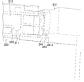
なお、図32〜図36において、図5に示した構成要素と同様の機能を果たす部分には同一の符号を付している。 32 to 36, the same reference numerals are given to portions that perform the same functions as the components shown in FIG.
本体200は、図5に示した例の構成において、液晶表示装置20に設けられているインバータ基板を収容する凹部(以下、インバータ基板収容凹部という)520、液晶表示装置20の上方向の移動を規制する段部(以下、上方向移動規制段部という)531,532、および液晶表示装置20を本体200に固定するための4つのボス541,542,543,544を追加した構成になっている。
In the configuration of the example shown in FIG. 5, the
本体200には、所定の部位に、本体200の内側に滞留する熱を外部に放熱するための複数の切り欠き部(孔)551が形成されている。
The
インバータ基板収容凹部520の底部には、インバータ基板から発せられる熱を外部に放熱するための複数の孔521が形成されている。
A plurality of
ところで、実施の形態1で説明したように本体部2(の本体200)には、液晶表示装置20の前方向の移動を規制する取付係合部210,230、および液晶表示装置20の下端部を支持する段部(以下、下端支持段部)517,518が設けられている。
By the way, as described in the first embodiment, the main body 2 (the main body 200) includes the mounting
すなわち、本体200には、液晶表示装置20に関し、その下端を支持する下端支持段部517,518(図34および図35参照)、その上方向の移動を規制する上方向移動規制段部531,532(上方向移動規制段部531に関して図33および図36参照)、その上端を支持する突出部の機能を有する取付係合部210,230(取付係合部210に関して図33および図36参照)が設けられている。
That is, the
なお、下端支持段部517,518においては、それぞれの上面517a,518aによって液晶表示装置20の下端部を支持するようになっている。
In the lower end support steps 517 and 518, the lower surfaces of the liquid
また、取付係合部210,230において、液晶表示装置20の上端部を支持し、かつ液晶表示装置20の前方向の移動を規制する突出部の機能を果たす部分は、図33に示すように、ベース部300の部位340の下側部位341である。つまり、前記突出部は、う遊技盤10を本固定するときの遊技盤固定部材、すなわち例えば取付係合部210におけるベース部300の部位340であると言える。
In addition, as shown in FIG. 33, the mounting
換言すれば、液晶表示装置20は、遊技盤10の背後に位置するように本体200に対し当該本体200の表面側から取り付けられ、かつ当該液晶表示装置20の上端が突出部によって前方向の移動が規制されるとともに、当該液晶表示装置20の下端が下端支持段部によって支持される。
In other words, the liquid
このように本実施の形態2においては、遊技盤10を固定するための上側の2つの取付係合部210,230を利用して、液晶表示装置20の仮固定を行うことが可能である。
As described above, in the second embodiment, the liquid
再度、図32を参照して説明する。下端支持段部517,518のそれぞれの上面517a,518aから、取付係合部210,230におけるベース部300の部位340の下側部位341の先端面までの距離(高さ)H1は、図26に示した液晶表示装置20の高さHよりも短くなっている。
Again, a description will be given with reference to FIG. The distance (height) H1 from the
すなわち、液晶表示装置20の下端を下端支持段部517,518のそれぞれの上面517a,518aに載置し、しかも液晶表示装置20を上面517a,518aに対し垂直にした場合に、当該液晶表示装置20の上端がベース部300の部位340の下側部位341と接して、当該液晶表示装置20の前方向の移動を規制するように、下端支持段部517,518と取付係合部210,230(のベース部300)とが配置されるようになっている。
That is, when the lower end of the liquid
また、本体200の凹部500における側部W1と側部W2との間の距離(幅)は、図26に示す液晶表示装置20の幅Wよりも多少長くなっている。すなわち、側部W1と側部W2との間の幅は、液晶表示装置20を凹部500に取り付けたときに、液晶表示装置20に設けられている4つの固定部22〜25の4つの孔22a〜25aと、本体200の凹部500に設けられている4つのボス541〜544とが略一致するように、当該液晶表示装置20の取り付けが可能で、かつ凹部500の側部W1および側部W2によって当該液晶表示装置20の左右方向の移動が規制できる、幅になっている。
Further, the distance (width) between the side portion W1 and the side portion W2 in the
このような前提条件の下で、液晶表示装置20の上端がベース部300の部位340の下側部位341と接する状態で、液晶表示装置20の下端を下端支持段部517,518のそれぞれの上面517a,518aに載置したときの、取付係合部210近傍の液晶表示装置20の取付状態を図37に示し、また、下端支持段部517近傍の液晶表示装置20の取付状態を図38に示し、さらに、下端支持段部518近傍の液晶表示装置20の取付状態を図39に示す。
Under such preconditions, the lower end of the liquid
ちなみに、図37に示す例は、図33に示す例において液晶表示装置20が取り付けられた状態であり、図38に示す例は、図34に示す例において液晶表示装置20が取り付けられた状態であり、図39に示す例は、図35に示す例において液晶表示装置20が取り付けられた状態である。
Incidentally, the example shown in FIG. 37 is a state where the liquid
なお、既に説明したように液晶表示装置20の背面にインバータ基板が取り付けられ、さらにカバーケース21が取り付けられているので(図25参照)、液晶表示装置20の背面側には凸部が形成された状態になっている。しかし、その凸部(カバーケース21)は、図40および図41に示すように、本体200の凹部500に形成されたインバータ基板収容凹部520に収容(嵌合)されるようになっている。
As already described, since the inverter board is attached to the back surface of the liquid
そのため、液晶表示装置20を本体200に対し当該本体200の表面側から取り付けたとしても、カバーケース21がインバータ基板収容凹部520に収容されるので、当該液晶表示装置20を、例えば前方向等に傾くことなく、所定の取り付け状態で本体200に取り付けることができる。
Therefore, even if the liquid
ところで、図42に示すように、例えば取付係合部210(可動規制部400は省略)においては、ベース部300の部位340と本体部2の部材との間は、液晶表示装置20の厚さd1以上の所定の距離d2だけ離間されている。
Incidentally, as shown in FIG. 42, for example, in the mounting engagement portion 210 (the movable restricting
また、ベース部300つまり部位340(の下側部位341)を本体200の上方向移動規制段部531に取り付けた場合は、下側部位(遊技盤固定部材)341の底面の位置は、上方向移動規制段部531の底面の位置よりも距離Lだけ低い。つまり下側部位(遊技盤固定部材)341の底面と上方向移動規制段部531の底面との間に、距離Lの段差が形成されていることになる。
Further, when the
上述した構成において、作業者は、下側部位341と上方向移動規制段部531との間の空間に、液晶表示装置20の上側が介在するように入れ、その後、当該液晶表示装置20を矢印A方向に回転させ、さらに、液晶表示装置20の下側を本体200の下端支持段部517,518(図34および図35参照)に載置するようにする。
In the above-described configuration, the operator puts the liquid
これにより、液晶表示装置20の上側は下側部位341の側面341aに接するので、液晶表示装置20の下側が本体200の下端支持段部517,518に載置されている液晶表示装置20は、前方向に倒れることはない(図42および図43参照)。これで、液晶表示装置20の仮固定が終了したことになる。
Thereby, since the upper side of the liquid
このとき、液晶表示装置20に設けられている4つの固定部22,23,24,25(図26参照)の4つの孔22a,23a,24a,25aと、本体200に設けられている4つのボス541,542,543,544(図32参照)とが略一致しているので、当該液晶表示装置20は位置決めされた状態で仮固定されたことになる。そのため、次の作業である本固定を容易に行うことができるようになる。
At this time, four
その後、液晶表示装置20は、ネジなどの固定部材が、固定部22,23,24,25の孔22a,23a,24a,25aを介して、本体200のボス541,542,543,544にネジ止めされることで、本固定される。
Thereafter, in the liquid
上述したようにして、液晶表示装置20が本体200に本固定され、さらに、上述したように遊技盤10が本固定された場合の取付係合部(のベース部)においては、液晶表示装置20と遊技盤10とは、例えば図44に示すような配置関係で、取り付けられていることになる。すなわち、遊技盤10の背後に液晶表示装置20が配置されている。なお、図44においては、遊技盤10に設けられている取付部、取付係合部210の可動規制部400、液晶表示装置20に設けられているインバータ基板およびカバーケース21などは図示していない。
As described above, the liquid
以上説明したように、本実施の形態2によれば、次の(1)〜(10)の作用効果を期待することができる。 As described above, according to the second embodiment, the following effects (1) to (10) can be expected.
(1)液晶表示装置20を本体200に対しその表面側から取り付けるとともに、演出制御基板(表示制御基板)721を有する制御系ケース70を本体200に対しその背面側から取り付けているので、従来の技術においては必要であった本体200に対する表示制御基板用の大きな開口部を、設ける必要がなく、本体200の剛性を大きくすることができる。
(1) Since the liquid
(2)本体200に対し当該本体200の背面側から取り付けられた制御系ケース70に内蔵する演出制御基板(表示制御基板)721に着脱可能に装着されるROMカートリッジ(記憶装置)724は、遊技機の機種に応じた演出に関する情報を記憶するようにしているので、新たな機種に対応するROMカートリッジ(記憶装置)と、旧機種に対応するROMカートリッジ(記憶装置)(つまり現在装着されているROMカートリッジ)とを交換することで機種の変更が可能となる。これにより、本体200の剛性を大きくすることができ、かつ機種の変更を容易に実施することができる。
(2) A ROM cartridge (storage device) 724 detachably attached to an effect control board (display control board) 721 built in a
(3)透光性部材で形成される遊技盤10は、当該透光性部材を介して液晶表示装置20を視認可能に本体200に対し当該本体200の表面側から取り付けられるようになっているので、遊技盤10に施されるべき例えば模様や文字を、当該模様や文字に対応する画像として液晶表示装置20によって表示するようにした場合には、遊技者からは遊技盤10に前記模様や文字が施されているように見えることとなり、よって、遊技機の機種に対応して遊技盤に施されるべき例えば模様や文字を変更したい場合であっても、当該遊技盤10を交換することなく、所望の模様や文字に対応する画像データを記憶したROMカートリッジを交換するのみで機種の変更が可能になる。
(3) The
(4)裏面にインバータ基板を備えた液晶表示装置20であっても、本体200に対しその表面側から取り付けることができるので、液晶表示装置20を本体200に容易に取り付けることができ、インバータ基板収容凹部520により本体200の剛性を更に大きくすることができる。
(4) Even if it is the liquid
(5)インバータ基板から発する熱がインバータ基板収容凹部520に形成された複数の孔521から放熱されるので、放熱効果を向上させることが可能になる。
(5) Since heat generated from the inverter board is radiated from the plurality of
(6)液晶表示装置20の下端に関しては、当該液晶表示装置20の下端を本体200に設けられた下端支持段部517,518に支持(載置)させればよいので、液晶表示装置20の取り付けが容易で、かつ安定した固定状態を維持できるとともに、下端支持段部517,518により本体200の剛性を更に大きくすることができる。
(6) Regarding the lower end of the liquid
(7)液晶表示装置20は、本体200に設けられた上方向移動規制段部531,532によって上方向の移動が規制されるので、液晶表示装置20を安定した固定状態に維持できるとともに、上方向移動規制段部531,532により本体200の剛性を更に大きくすることができる。
(7) Since the upward movement of the liquid
(8)液晶表示装置20は、遊技盤10の背後に位置するように本体200に対し当該本体200の表面側から取り付けられ、かつ当該液晶表示装置20の上端が本体200の凹部500に設けられた取付係合部210,230のベース部(突出部)300によって前方向の移動が規制されるとともに、当該液晶表示装置20の下端が本体200の凹部500に設けられた下端支持段部517,518によって支持されるようになっているので、液晶表示装置20に設けられている4つの固定部22〜25の4つ孔22a〜25aと、本体200の凹部500に設けられている4つのボス541〜544とが略一致しているので、液晶表示装置20の位置決めを容易に行うことができる。すなわち、液晶表示装置20は位置決めされた状態で仮固定されるので、次の作業を容易に行うことができる。
(8) The liquid
(9)位置決めされた状態で仮固定されている液晶表示装置20に対し本固定を実施するときは、作業者が液晶表示装置20を押さえる(支持する)ことなく、例えば両手を使用して固定(本固定)することができ、しかも上述したように4つの固定部22〜25の4つの孔22a〜25aと4つのボス541〜544とが略一致しているので、ビス止め作業を容易に行うことができ、これにより液晶表示装置20の取り付けの作業効率を向上させることが可能になる。
(9) When the main fixing is performed on the liquid
(10)遊技盤10を固定するための上側の2つの取付係合部210,230を利用して液晶表示装置20の仮固定を行うことができるので、液晶表示装置20を固定(仮固定)するための部材、例えば液晶表示装置20が前方向に倒れないようにする部材を抑制することができる。具体的には、取付係合部210,230におけるベース部300の部位340の下側部位(遊技盤固定部材)341を、液晶表示装置20の前方向の移動を規制する突出部として用いるようにしているので、取付係合部210,230におけるベース部300を前記突出部と兼用させることができ、液晶表示装置20の前方向の移動を規制する専用の突出部材を用いる必要がなく、必要最低限の部材を用いて液晶表示装置20の仮固定が可能になる。
(10) Since the liquid
(実施の形態3) (Embodiment 3)
次に、本発明の実施の形態3に係る遊技機について添付図面を参照して説明する。
Next, a gaming machine according to
この実施の形態3に係る遊技機は、基本的には、上述した実施の形態1および実施の形態2に係る遊技機の構造(構成)および機能を有している。ここでは、実施の形態1および実施の形態2との相違点のみについて説明する。 The gaming machine according to the third embodiment basically has the structure (configuration) and function of the gaming machine according to the first and second embodiments described above. Here, only differences from the first embodiment and the second embodiment will be described.
なお、実施の形態1では遊技盤の取り付け(取付構造)に着目して説明し、実施の形態2では表示装置の取り付け(取付構造)に着目して説明したのに対し、この実施の形態3では、本体に備えられた係止部による遊技盤と表示装置との取り付け(取付構造)に着目して説明する。 In the first embodiment, the description will focus on the mounting (mounting structure) of the game board, and in the second embodiment, the description will focus on the mounting (mounting structure) of the display device. Then, it demonstrates paying attention to attachment (attachment structure) of the game board and display apparatus by the latching | locking part with which the main body was equipped.
ここで、図45は実施の形態3における表示装置と遊技盤との配置関係を可動規制部を除いた状態で示す斜視図、図46は実施の形態3における表示装置と遊技盤との配置関係を可動規制部を除いた状態で図45とは異なるアングルで示す斜視図、図47は実施の形態3における表示装置と遊技盤との配置関係を可動規制部を含めて示す斜視図である。 Here, FIG. 45 is a perspective view showing the arrangement relationship between the display device and the game board in the third embodiment, excluding the movable restricting portion, and FIG. 46 is the arrangement relationship between the display device and the game board in the third embodiment. FIG. 47 is a perspective view showing an arrangement relationship between the display device and the game board in the third embodiment including the movable restricting portion in a state in which the movable restricting portion is excluded.
遊技盤10および液晶表示装置20は、ともに本体200に対して前方向から取り付けられ、液晶表示装置20が遊技盤10の背面側に位置するようになることから、まず液晶表示装置20を取り付け、次に遊技盤10を取り付けることになる。
Both the
そこで、以下においては、このような取り付け順序に従って、液晶表示装置20の取り付けについて説明し、続いて遊技盤10の取り付けについて説明する。
Therefore, in the following, the attachment of the liquid
液晶表示装置20の取り付けにおいて、作業者は、取付係合部210,230を構成するベース部300の下側部位341と上方向移動規制段部531,532(図32、図33、図36、図37、図42、図43)との間の空間に、液晶表示装置20の上側が介在するように本体2の前方向から入れ、その後、当該液晶表示装置20の上側を手前に引いて下側部位341に当接させるようにしながら(図42参照)、さらに、液晶表示装置20の下側を本体200の下端支持段部517,518(図34、図35)に載置する。
In attaching the liquid
これにより、液晶表示装置20の上側は取付係合部210,230を構成するベース部300の下側部位341の側面341aに接するので、つまり取付係合部210,230によって液晶表示装置20の上端が係止される(液晶表示装置20の上端の一部が覆われる)ので(図45〜図47参照)、下側が本体200の下端支持段部517,518に載置されている液晶表示装置20は、取付係合部210,230によって液晶表示装置20の前方向への動きが規制されることとなり、前方向に倒れることはない。
Accordingly, the upper side of the liquid
このようにして、図45〜図47に示すように、液晶表示装置20が本体200に対して仮固定される。
In this way, the liquid
なお、前述のように、液晶表示装置20は、ネジなどの固定部材が、固定部22,23,24,25の孔22a,23a,24a,25aを介して、本体200のボス541,542,543,544にネジ止めされることで本固定される。
As described above, in the liquid
このようにして、液晶表示装置20が取付係合部210,230によって本体200に仮固定された後、当該液晶表示装置20の前方側に遊技盤10が固定(本固定)される。
In this manner, after the liquid
遊技盤10の取り付けにおいて、作業者は、取付係合部210,230のベース部300の取り付けられた移動規制部400を移動許容位置P1(図20)としておく。ベース部300に形成されて前後方向に延びる案内溝310は前方が開放された状態となっているので、次に、遊技盤10の四隅にそれぞれ設けられた取付部110,120,130,140のピン部111、121,131,141を、取付係合部210,220,230,240のベース部300の案内溝310にそれぞれ挿入して後方へと押し込み、所定の支持位置である凹部311に落とし込む(収容させる)。
In attaching the
このように遊技盤10の4カ所の取付部110,120,130,140にそれぞれ設けられたピン部111、121,131,141が取付係合部210,220,230,240の凹部311に落とし込まれ、前方規制部320により前方向への動きが規制されることにより、図45および図46に示すように、遊技盤10は、液晶表示装置20の前方において本体200に対して仮固定される。
In this way, the
遊技盤10の仮固定が終了したならば、次に、これを本固定するために、作業者は、図47に示すように、取付係合部210,230のベース部300の取り付けられた可動規制部400を、移動許容位置P1から移動規制位置P2(図20)へと移動させる。これにより、遊技盤10は、取付係合部210,230の可動規制部400および下方向規制部513,514によって上下方向の動きが確実に規制されることになる。
When the temporary fixing of the
これに加えて、前述のように、移動規制状態にある取付係合部210,230の可動規制部400のストッパ部420の部位420aにブラケット1100が接するとともに、可動規制部400の突起部460とブラケット1100の係合部117とが係合するので、より一層、前方向への動きが規制される(図23参照)。さらに、取付係合部210,230の可動規制部400および下方向規制部513,514によって上下方向の動きが規制されているときは、左右方向規制部515,516によって左右方向の動きが規制されていることになる。
In addition, as described above, the
これにより、遊技盤10は、上下方向、左右方向および前方向の動きが規制されるので、本体200に確実に本固定されることとなる。
As a result, the
そして、このように、本体200に備えられた取付係合部210,230によって、遊技盤10の係止(すなわち固定)と液晶表示装置20の仮固定とが行われる。つまり、取付係合部210,230が遊技盤10の係止(固定)と液晶表示装置20の仮固定とを兼用している。したがって、遊技盤固定部材としての取付係合部210,230の機能が遊技盤10の固定のみならず、液晶表示装置20の仮固定にまで広がることになるので、取付係合部210,230の汎用性の向上を図ることが可能になる。
In this manner, the
これにより、液晶表示装置20を仮固定するための専用の部品が不要になって部品点数の削減を図ることができ、遊技機の組立工数の削減およびコストダウンを図ることが可能になる。
As a result, a dedicated part for temporarily fixing the liquid
また、液晶表示装置20は本体200に対して前方向から取り付けられ、取付係合部210,230は液晶表示装置20の一部を覆ってこの液晶表示装置20の前方向への動きを規制しているので、液晶表示装置20の着脱作業の際に、本体200の背面に備えられて電子部品の搭載された基板等が障害となることはなく、着脱作業を極めて容易に行うことが可能になる。また、液晶表示装置20の一部を取付係合部210,230で覆うようにするだけで液晶表示装置20の取り付け方向である前方向への動きが規制されるので、液晶表示装置20の仮固定を容易に行うことができる。
Further, the liquid
なお、図45〜図47において、ベース部300に設けられた軸部330は、実施の形態1、2に示す場合とは異なり、長さ方向に間隔を空けて2分割されるとともに、先端には径方向外方に突出したフランジ330aが形成されている。
In FIGS. 45 to 47, the
これにより、可動規制部400を取り付ける際には、分割された軸部330が相互に接近する方向に弾性変形して可動規制部400に挿入される。また、取り付け後には、弾性変形した軸部330が元の形状に復帰することにより、フランジ330aが可動規制部400に係止して可動規制部400の離脱を阻止するので、可動規制部400の取り付け信頼性が向上する。
Thus, when the movable restricting
以上の説明においては、本発明をパチンコ遊技機本体が遊技台に取り付けられた遊技機に適用した場合が説明されているが、本発明はこれに限定されるものではなく、パチスロ遊技機(スロットマシン)、雀球、スマートボールあるいはゲームセンターに設置された各種のゲーム機など、種々の遊技機に適用することが可能である。 In the above description, the case where the present invention is applied to a gaming machine in which the main body of the pachinko gaming machine is attached to the gaming machine is described, but the present invention is not limited to this, and a pachislot gaming machine (slot Machine), sparrow balls, smart balls, or various game machines installed in a game center.
1 遊技機
2 本体部
2a 木枠
3 ガラス扉
4 上皿部
5 下皿部
6 カバー
7 ハンドル
10 遊技盤
20 液晶表示装置
20a 表示領域
21 カバーケース
22,23,24,25 固定部
30 開閉扉
41 払出制御回路
42 発射制御回路
43 カードユニット
50 主制御回路
51 メインCPU
60 演出制御回路
61 サブCPU
62 プログラムROM
65 画像制御回路
70 制御系ケース
71 制御系ユニット
72 外側ケース
110,120,130,140 取付部
111,121,131,141 ピン部
117 係合部
118 圧接部
200 本体
210,220,230,240 取付係合部(係止部)
300 ベース部
310 案内溝
311 凹部
320 前方向規制部
330 軸部
340 部位
341 下側部位(突出部、遊技盤固定部材)
400 可動規制部(上方向規制部)
410 支持部
420 ストッパ部
421 切り欠き部
431,432,433 凹部
434 凸部
460 突出部
500 凹部
513,514 下方向規制部
515,516 左右方向規制部
517,518 下端支持段部(支持部)
520 凹部
521 孔
531,532 上方向移動規制段部
541,542,543,544 ボス
710 主制御基板ユニット
720 演出制御基板ユニット
721 演出制御基板(表示制御基板)
722 基板上部ケース
723 基板下部ケース
724 ROMカートリッジ(記憶装置)
730 電源基板ユニット
740 発射制御基板ユニット
750 払出制御基板ユニット
760 CR中継基板ユニット
1100 ブラケット
P1 移動許容位置
P2 移動規制位置
DESCRIPTION OF
60
62 Program ROM
65
300
400 Movable restriction part (upward restriction part)
410
520 Recessed
722 Substrate
730 Power
Claims (4)
前記遊技盤の背面側に配置され、所定の画像を表示する表示装置と、
前記遊技盤および前記表示装置が取り付けられる本体と、
前記本体に設けられ、前記表示装置の前面上部を覆うとともに前記表示装置の前面側で前記遊技盤を前記本体へ係止する係止部と、
前記本体に設けられ、前記表示装置の下端が載置されて当該表示装置の下端を支持する支持部と、
を有し、
前記表示装置は、前記本体に対して前方向から取り付けられ、下端が前記支持部に載置された状態で前面上部が前記係止部により前方向への動きが規制されることにより前記本体へ仮固定される、
ことを特徴とする遊技機。 A game board having a game area in which game balls roll down,
A display device arranged on the back side of the game board and displaying a predetermined image;
A main body to which the game board and the display device are attached;
A locking portion provided on the main body, covering a front upper portion of the display device and locking the game board to the main body on the front surface side of the display device ;
A support portion provided on the main body, on which a lower end of the display device is placed and supports the lower end of the display device;
Have
The display device is attached to the main body from the front direction, and the front upper portion is restrained from moving forward by the locking portion in a state where the lower end is placed on the support portion. Temporarily fixed,
A gaming machine characterized by that.
前記凹部の上部には、前方に突出して前記表示装置の上方向への移動を規制する上方向移動規制段部が設けられ、
前記係止部は、前記表示装置を仮固定したときに前記係止部により当該表示装置の前面上部が覆われる長さだけ前記上方向移動規制段部の下面よりも下方に突出して設けられている、
ことを特徴とする請求項1記載の遊技機。 A recess for accommodating and attaching the display device is formed on the front surface of the main body,
On the upper part of the concave portion, an upward movement restriction step portion that protrudes forward and restricts the upward movement of the display device is provided,
The locking portion is provided so as to protrude downward from the lower surface of the upward movement restricting step portion by a length that covers the upper front surface of the display device by the locking portion when the display device is temporarily fixed. Yes,
The gaming machine according to claim 1.
ことを特徴とする請求項2に記載の遊技機。 A plurality of holes are formed in the recess,
The gaming machine according to claim 2, wherein:
前記表示装置が前記本体に仮固定された位置において、前記表示装置に設けられたネジ穴と前記本体に設けられた取付ボスとが一致する、
ことを特徴とする請求項1、2または3記載の遊技機。 The display device is provided with screw holes, and the main body is provided with mounting bosses corresponding to the screw holes, respectively.
At a position where the display device is temporarily fixed to the main body, a screw hole provided in the display device and an attachment boss provided in the main body match.
The gaming machine according to claim 1, 2, or 3.
Priority Applications (1)
| Application Number | Priority Date | Filing Date | Title |
|---|---|---|---|
| JP2005182803A JP4211891B2 (en) | 2005-02-25 | 2005-06-23 | Game machine |
Applications Claiming Priority (2)
| Application Number | Priority Date | Filing Date | Title |
|---|---|---|---|
| JP2005050168 | 2005-02-25 | ||
| JP2005182803A JP4211891B2 (en) | 2005-02-25 | 2005-06-23 | Game machine |
Publications (3)
| Publication Number | Publication Date |
|---|---|
| JP2006263433A JP2006263433A (en) | 2006-10-05 |
| JP2006263433A5 JP2006263433A5 (en) | 2008-11-13 |
| JP4211891B2 true JP4211891B2 (en) | 2009-01-21 |
Family
ID=37199981
Family Applications (1)
| Application Number | Title | Priority Date | Filing Date |
|---|---|---|---|
| JP2005182803A Expired - Fee Related JP4211891B2 (en) | 2005-02-25 | 2005-06-23 | Game machine |
Country Status (1)
| Country | Link |
|---|---|
| JP (1) | JP4211891B2 (en) |
Families Citing this family (1)
| Publication number | Priority date | Publication date | Assignee | Title |
|---|---|---|---|---|
| JP4753853B2 (en) * | 2006-12-12 | 2011-08-24 | 株式会社ソフイア | Game machine |
-
2005
- 2005-06-23 JP JP2005182803A patent/JP4211891B2/en not_active Expired - Fee Related
Also Published As
| Publication number | Publication date |
|---|---|
| JP2006263433A (en) | 2006-10-05 |
Similar Documents
| Publication | Publication Date | Title |
|---|---|---|
| JP5912815B2 (en) | Pachinko machine | |
| JP2009018019A (en) | Game machine | |
| JP6603921B2 (en) | Gaming machine and gaming device | |
| JP2013233295A (en) | Pachinko machine | |
| JP2006102473A (en) | Game machine | |
| JP5758092B2 (en) | Game machine | |
| JP2017221469A (en) | Game machine and game device | |
| JP6783455B2 (en) | Game machine | |
| JP6016967B2 (en) | Game machine | |
| JP6280071B2 (en) | Game machine | |
| JP4125318B2 (en) | Game machine | |
| JP4211891B2 (en) | Game machine | |
| JP6290132B2 (en) | Game machine | |
| JP4209408B2 (en) | Game machine | |
| JP5374838B2 (en) | Game machine | |
| JP6674097B2 (en) | Gaming machine | |
| JP5023302B2 (en) | Game machine | |
| JP2006087551A (en) | Game machine | |
| JP6924356B2 (en) | Pachinko machine | |
| JP2008023119A (en) | Game machine | |
| JP4205065B2 (en) | Game machine | |
| JP2018023443A (en) | Game machine | |
| JP7213633B2 (en) | game machine | |
| JP2018023444A (en) | Game machine | |
| JP3928950B2 (en) | Pachinko machine |
Legal Events
| Date | Code | Title | Description |
|---|---|---|---|
| A621 | Written request for application examination |
Free format text: JAPANESE INTERMEDIATE CODE: A621 Effective date: 20071210 |
|
| A521 | Written amendment |
Free format text: JAPANESE INTERMEDIATE CODE: A523 Effective date: 20080929 |
|
| A871 | Explanation of circumstances concerning accelerated examination |
Free format text: JAPANESE INTERMEDIATE CODE: A871 Effective date: 20080929 |
|
| TRDD | Decision of grant or rejection written | ||
| A975 | Report on accelerated examination |
Free format text: JAPANESE INTERMEDIATE CODE: A971005 Effective date: 20081016 |
|
| A01 | Written decision to grant a patent or to grant a registration (utility model) |
Free format text: JAPANESE INTERMEDIATE CODE: A01 Effective date: 20081021 |
|
| A01 | Written decision to grant a patent or to grant a registration (utility model) |
Free format text: JAPANESE INTERMEDIATE CODE: A01 |
|
| A61 | First payment of annual fees (during grant procedure) |
Free format text: JAPANESE INTERMEDIATE CODE: A61 Effective date: 20081021 |
|
| FPAY | Renewal fee payment (event date is renewal date of database) |
Free format text: PAYMENT UNTIL: 20111107 Year of fee payment: 3 |
|
| R150 | Certificate of patent or registration of utility model |
Ref document number: 4211891 Country of ref document: JP Free format text: JAPANESE INTERMEDIATE CODE: R150 Free format text: JAPANESE INTERMEDIATE CODE: R150 |
|
| FPAY | Renewal fee payment (event date is renewal date of database) |
Free format text: PAYMENT UNTIL: 20111107 Year of fee payment: 3 |
|
| S531 | Written request for registration of change of domicile |
Free format text: JAPANESE INTERMEDIATE CODE: R313532 |
|
| S533 | Written request for registration of change of name |
Free format text: JAPANESE INTERMEDIATE CODE: R313533 |
|
| FPAY | Renewal fee payment (event date is renewal date of database) |
Free format text: PAYMENT UNTIL: 20111107 Year of fee payment: 3 |
|
| R350 | Written notification of registration of transfer |
Free format text: JAPANESE INTERMEDIATE CODE: R350 |
|
| FPAY | Renewal fee payment (event date is renewal date of database) |
Free format text: PAYMENT UNTIL: 20111107 Year of fee payment: 3 |
|
| FPAY | Renewal fee payment (event date is renewal date of database) |
Free format text: PAYMENT UNTIL: 20121107 Year of fee payment: 4 |
|
| R250 | Receipt of annual fees |
Free format text: JAPANESE INTERMEDIATE CODE: R250 |
|
| FPAY | Renewal fee payment (event date is renewal date of database) |
Free format text: PAYMENT UNTIL: 20121107 Year of fee payment: 4 |
|
| FPAY | Renewal fee payment (event date is renewal date of database) |
Free format text: PAYMENT UNTIL: 20131107 Year of fee payment: 5 |
|
| R250 | Receipt of annual fees |
Free format text: JAPANESE INTERMEDIATE CODE: R250 |
|
| R250 | Receipt of annual fees |
Free format text: JAPANESE INTERMEDIATE CODE: R250 |
|
| R250 | Receipt of annual fees |
Free format text: JAPANESE INTERMEDIATE CODE: R250 |
|
| R250 | Receipt of annual fees |
Free format text: JAPANESE INTERMEDIATE CODE: R250 |
|
| R250 | Receipt of annual fees |
Free format text: JAPANESE INTERMEDIATE CODE: R250 |
|
| R250 | Receipt of annual fees |
Free format text: JAPANESE INTERMEDIATE CODE: R250 |
|
| R250 | Receipt of annual fees |
Free format text: JAPANESE INTERMEDIATE CODE: R250 |
|
| LAPS | Cancellation because of no payment of annual fees |