JP5374838B2 - Game machine - Google Patents

Game machine Download PDF

Info

Publication number
JP5374838B2
JP5374838B2 JP2007173811A JP2007173811A JP5374838B2 JP 5374838 B2 JP5374838 B2 JP 5374838B2 JP 2007173811 A JP2007173811 A JP 2007173811A JP 2007173811 A JP2007173811 A JP 2007173811A JP 5374838 B2 JP5374838 B2 JP 5374838B2
Authority
JP
Japan
Prior art keywords
housing
unit
casing
door
plate
Prior art date
Legal status (The legal status is an assumption and is not a legal conclusion. Google has not performed a legal analysis and makes no representation as to the accuracy of the status listed.)
Active
Application number
JP2007173811A
Other languages
Japanese (ja)
Other versions
JP2009011418A5 (en
JP2009011418A (en
Inventor
達也 田中
栄司 久保田
Current Assignee (The listed assignees may be inaccurate. Google has not performed a legal analysis and makes no representation or warranty as to the accuracy of the list.)
Sanyo Bussan Co Ltd
Original Assignee
Sanyo Bussan Co Ltd
Priority date (The priority date is an assumption and is not a legal conclusion. Google has not performed a legal analysis and makes no representation as to the accuracy of the date listed.)
Filing date
Publication date
Application filed by Sanyo Bussan Co Ltd filed Critical Sanyo Bussan Co Ltd
Priority to JP2007173811A priority Critical patent/JP5374838B2/en
Publication of JP2009011418A publication Critical patent/JP2009011418A/en
Publication of JP2009011418A5 publication Critical patent/JP2009011418A5/ja
Application granted granted Critical
Publication of JP5374838B2 publication Critical patent/JP5374838B2/en
Active legal-status Critical Current
Anticipated expiration legal-status Critical

Links

Images

Abstract

<P>PROBLEM TO BE SOLVED: To provide a game machine having a simple fraudulence-preventing structure and providing a desired fraudulence-suppressing effect. <P>SOLUTION: A slot machine 10 has a casing body 11 and a front door 12 for covering the front surface of the casing body. The inside of the casing body 11 is removably provided with a surface-replacing unit 400 mounted with reel devices 650 and a main control device within an inside casing body. A plurality of hollow blocks are provided in back of a door-supporting fitting 200 provided on the inside of a side panel of the casing body 11 and at a part of the side panel of the casing body 11 facing a side panel portion of the inside casing body. The hollow blocks are configured so as to abut on a guide rib formed at the side panel portion of the inside casing body. <P>COPYRIGHT: (C)2009,JPO&amp;INPIT

Description

本発明は、遊技機に関するものである。   The present invention relates to a gaming machine.

遊技機の一種であるスロットマシンには、筐体内部にリール装置、メダル払出装置、各種制御装置(主基板を含む)、電源装置等が搭載され、筐体の前面側に開閉可能に取り付けられる前面扉には補助表示装置、メダル投入装置、スタートレバー、ストップボタン等が設けられているものがある。遊技に際しては、遊技回毎に、遊技者によりメダル投入(又はベット操作)や始動操作が行われることでリール装置のリールが回転を開始し、当該リールの外周面に付された図柄が表示を通じて可変表示される。リールの回転開始後には、遊技者によりストップボタンが押し操作されることでリールが回転を停止する。そして、リール停止時において表示を通じて視認される停止図柄に応じてメダルの払出等の特典が遊技者に付与される。 A slot machine, which is a type of gaming machine, is equipped with a reel device, a medal payout device, various control devices (including a main board), a power supply device, and the like inside the housing, and is attached to the front side of the housing so that it can be opened and closed. auxiliary display device in the front door, token input device, the start lever, there is the stop button and the like. When playing a game, a player inserts a medal (or bet operation) or starts a reel every time the game is started, and the reel of the reel device starts to rotate, and a symbol attached to the outer peripheral surface of the reel is displayed on the display unit. Ru is the variable display through. After starting rotation of the reels, the reels in a is pressed a stop button operation Turkey stops rotating by the player. The benefits payout such medals Ru is awarded to the player in response to the stop symbols to be visible through the display unit at the time of reel stop.

近年では、より斬新で面白みのある遊技を遊技者に提供すること等を目的として、遊技機の機種変更が短いサイクルで行われる傾向にある。遊技機業界においてはこのような状況に対応すべく、リール装置と主基板とを枠状の支持体に搭載して表示ユニット(交換用のユニット)を構成し、同表示ユニットを筐体内部に着脱自在に設けるようにした分離型スロットマシンが提案されている(例えば特許文献1参照)。このように表示ユニットを有するスロットマシンにおいては、筐体の側板に設けられる構成部品(例えば扉支持金具や中継基板等)を固定したままで表示ユニットの着脱を行うことにより、当該表示ユニット着脱の作業性の向上が図られている。
特開2004−670号公報
In recent years, for the purpose of, etc. to provide a game with new and interesting Ri good to the player, there is a tendency that the model change of the gaming machine is carried out in a short cycle. In the gaming machine industry, in order to cope with such a situation , a reel unit and a main board are mounted on a frame-shaped support to form a display unit (a replacement unit), and the display unit is placed inside the housing. A separation-type slot machine that is detachably provided has been proposed (see, for example, Patent Document 1). Thus, in a slot machine having a display unit, the display unit can be attached / detached by attaching / detaching the display unit while fixing components (for example, a door support bracket and a relay board) provided on the side plate of the housing. Workability is improved.
Japanese Patent Laid-Open No. 2004-670

上述した着脱式の表示ユニットを有するスロットマシンにおいては、表示ユニットの着脱機能に未だ改善の余地がある。In the slot machine having the detachable display unit described above, there is still room for improvement in the detachable function of the display unit.

本発明は、上記事情に鑑みてなされたものであり、表示ユニットを好適に脱することができる遊技機を提供することを目的とするものである。 The present invention has been made in view of the above circumstances, it is an object to provide a gaming machine capable Rukoto to Dassu suitably wearing the display unit.

本発明は、The present invention
遊技機前方に開放された筐体と、A housing opened in front of the gaming machine;
遊技に関する各種制御を実施する主制御装置、及び周方向に複数種の絵柄が配設された周回体を複数有しこれら周回体を回転させることで絵柄を変動表示させる絵柄表示装置を、少なくとも左右両側に側壁部を有するユニット本体に搭載してなり、前記筐体の内部に着脱自在に装着される表示ユニットと、A main control device that performs various controls related to the game, and a pattern display device that has a plurality of circulating bodies in which a plurality of types of patterns are arranged in the circumferential direction and displays the patterns by changing the rotating bodies, at least left and right A display unit that is mounted on a unit body having side walls on both sides, and is detachably mounted inside the housing;
前記側板の前端部に固定され、前記筐体の開口内側に張り出している筐体側構成部品と、A casing-side component fixed to the front end of the side plate and protruding inside the opening of the casing;
前記筐体の左右両側板にそれぞれ設けられ、同筐体内にて前記ユニット本体を移動可能に支持するユニット支持部材とA unit support member provided on each of the left and right side plates of the housing, and movably supporting the unit body in the housing;
を備え、With
前記ユニット本体が前記ユニット支持部材に接触した状態で前記表示ユニットが前記筐体の奥側に移動することにより、前記筐体側構成部品が前記筐体の側板に固定された状態のまま、同表示ユニットが前記筐体に装着される構成となっており、When the display unit moves to the back side of the casing while the unit main body is in contact with the unit support member, the display is performed while the casing-side components are fixed to the side plate of the casing. The unit is configured to be attached to the housing,
前記筐体の側板は木製の板材からなり、The side plate of the housing is made of a wooden plate material,
前記筐体側構成部品の後方で且つ前記筐体の側板における前記ユニット本体の側壁部と対向する部位に取り付けられ、前記筐体の側板からの張出量が前記筐体側構成部品の同筐体の側板からの張出量よりも大きくなるように形成された張出部を備え、Attached to a part of the side plate of the casing facing the side wall of the unit main body behind the casing-side component, and the amount of protrusion from the side plate of the casing is that of the casing of the casing-side component It has an overhang part formed so as to be larger than the overhang amount from the side plate,
前記張出部は前後方向にずらして複数設けられており、それら張出部のうち前側の張出部が後側の張出部よりも前記ユニット支持部材に近い位置へ配置されていることを特徴とする。A plurality of the overhang portions are provided so as to be shifted in the front-rear direction, and among the overhang portions, the front overhang portion is disposed closer to the unit support member than the rear overhang portion. Features.

表示ユニットを好適に着脱することができる。The display unit can be suitably attached and detached.

はじめに、本実施の形態から抽出され得る発明を、必要に応じて効果等を示しつつ説明する。First, the invention that can be extracted from the present embodiment will be described while showing effects and the like as necessary.

以下の各手段は、「遊技機の一種であるスロットマシンには、筐体内部にリール装置、メダル払出装置、各種制御装置(主基板を含む)、電源装置等が搭載され、筐体の前面側に開閉可能に取り付けられる前面扉には補助表示装置、メダル投入装置、スタートレバー、ストップボタン等が設けられている。遊技に際しては、遊技回毎に、遊技者によりメダル投入(又はベット操作)や始動操作が行われることでリール装置のリールが回転を開始し、当該リールの外周面に付された図柄が表示窓を通じて可変表示されると共に補助表示装置により各種演出が表示される。リールの回転開始後には、遊技者によりストップボタンが押し操作されるか、或いは所定時間が経過することでリールが回転を停止する。そして、リール停止時において表示窓を通じて視認される停止図柄に応じてメダルの払出等、利益状態が遊技者に付与されるようになっている。近年では、遊技機業界における遊技内容の多様化に伴い、より斬新で面白みのある遊技を遊技者に提供するために、遊技機の機種変更が短いサイクルで行われる傾向にあり、これに対応してリール装置と主基板とを枠状の支持体に搭載して表示ユニット(交換用のユニット)を構成し、同表示ユニットを筐体内部に着脱自在に設けるようにした分離型スロットマシンが提案されている(例えば特開2004−670号公報参照)。このように表示ユニットを有するスロットマシンにおいては、筐体の側板に設けられる構成部品(例えば扉支持金具や中継基板等)を固定したままで表示ユニットの着脱を行うことにより、当該表示ユニット着脱の作業性の向上が図られている。しかしながら、表示ユニットの着脱時等に、筐体の側板に設けられた構成部品が取り外されることがなく、固定されたままとなる構成とした場合、筐体と表示ユニットとの間(特に、上述した構成部品の筐体奥側)に不正基板等を設置可能なスペースが生じるおそれがある。仮に不正基板が設置されると、当該不正基板等により故意に生成された不正信号やその他ノイズ等が各種制御装置等に入力される可能性があり、このような不正信号等によって、不正な大当たりが発生したり、メダル投入等を行うことなく遊技が可能となったりすることが懸念される。」という技術背景及び課題等を解決するためになされたものである。   The following means are as follows: “A slot machine, which is a kind of gaming machine, has a reel device, a medal payout device, various control devices (including a main board), a power supply device, etc. mounted on the inside of the housing. An auxiliary display device, a medal insertion device, a start lever, a stop button, etc. are provided on the front door that can be opened and closed on the side.In the game, the player inserts a medal (or bet operation) every game. When the start operation is performed, the reel of the reel device starts rotating, and the symbols attached to the outer peripheral surface of the reel device are variably displayed through the display window, and various effects are displayed by the auxiliary display device. After the start of rotation, the reel is stopped when the stop button is pressed by the player or a predetermined time elapses. Profit status is given to the player according to the stop pattern visually recognized through the game, etc. In recent years, with the diversification of game content in the gaming machine industry, it is more innovative and interesting. In order to provide games to players, the model change of gaming machines tends to be performed in a short cycle, and in response to this, the reel unit and the main board are mounted on a frame-shaped support body and a display unit (replacement) A separate type slot machine has been proposed in which the display unit is detachably provided inside the housing (see, for example, Japanese Patent Application Laid-Open No. 2004-670). In the slot machine having the display unit, the display unit is attached or detached while fixing the components (for example, a door support bracket or a relay board) provided on the side plate of the housing. However, when the display unit is attached or detached, the components provided on the side plate of the housing are not removed and remain fixed. There is a risk of creating a space where an illegal board or the like can be placed between the casing and the display unit (particularly, the inner side of the above-described component part). There is a possibility that an illegal signal or other noises intentionally generated by the player may be input to various control devices, etc., and such illegal signals etc. cause an illegal jackpot or without inserting a medal. This has been done to solve the technical background and problems.

手段1.遊技機前方に開放された筐体(筐体11)と、
遊技に関する各種制御を実施する主制御装置(主制御装置770)、及び周方向に複数種の絵柄が配設された周回体(リール655〜657)を複数有しこれら周回体を回転させることで絵柄を変動表示させる絵柄表示装置(リール装置650)を、少なくとも左右両側に側壁部(側板部410d,410e)を有するユニット本体(内側筐体410)に搭載してなり、前記筐体の内部に着脱自在に装着される表示ユニット(面替えユニット400)と、
前記筐体の側板(側板11d,11e)における前記ユニット本体の側壁部(側板部410d,410e)と対向する部位に設けられた筐体側構成部品(扉支持金具200、鉤受け金具220等)と
を備え、
前記筐体側構成部品が前記筐体の側板に固定された状態のまま、前記表示ユニットが着脱される遊技機において、
前記筐体側構成部品の後方で且つ前記筐体の側板における前記ユニット本体の側壁部と対向する部位に張出部(中空ブロック480,490)を設けたことを特徴とする遊技機。
Means 1. A housing (housing 11) opened in front of the gaming machine;
By having a plurality of revolving bodies (reels 655 to 657) in which a plurality of types of patterns are arranged in the circumferential direction, the main control apparatus (main control apparatus 770) that performs various controls relating to games is rotated. A pattern display device (reel device 650) for variably displaying a pattern is mounted on a unit main body (inner housing 410) having side wall portions (side plate portions 410d and 410e) on at least the left and right sides, A display unit (replacement unit 400) that is detachably mounted;
Case side component parts (door support fittings 200, barge fittings 220, etc.) provided on the side plates of the case (side plates 11d, 11e) facing the side wall portions (side plate portions 410d, 410e) of the unit main body. With
In the gaming machine in which the display unit is attached and detached while the casing side component is fixed to the side plate of the casing,
A gaming machine characterized in that an overhanging portion (hollow blocks 480, 490) is provided at a portion of the side plate of the housing facing the side wall of the unit main body behind the housing-side component.

手段1の遊技機では、主制御装置と絵柄表示装置とをユニット本体に搭載してなる表示ユニットが筐体に対し着脱自在な構成となっている。筐体の側板の内側には筐体側構成部品(例えば扉支持金具や中継基板等)が設けられているが、メンテナンス等の際には、同筐体側構成部品を取り外すことなく表示ユニットの着脱作業を行うことができ、同作業の煩雑化が抑制されている。また、仮に、不正行為者が筐体内に針金等の不正具を挿入した場合であっても、筐体内部にユニット本体の側壁部が存在するため、ユニット本体の内側(特に主制御装置)へのアクセスを困難なものとすることができる。   In the gaming machine of means 1, a display unit in which the main control device and the picture display device are mounted on the unit body is detachable from the housing. Case side components (for example, door support brackets and relay boards) are provided inside the case side plate. For maintenance, etc., the display unit can be attached and detached without removing the case side components. The complication of the work is suppressed. Further, even if an unauthorized person inserts a fraudulent tool such as a wire into the housing, the side wall of the unit body is present inside the housing, so that the inside of the unit body (particularly the main control device) Can be difficult to access.

しかしながら、上述のごとくユニット本体が少なくとも左右の側壁部を有する構成であることで、筐体の側板とユニット本体の側壁部との間に挟まれた空間が形成され、この空間が不正基板等の設置対象となってしまうことが懸念される。その側板と側壁部とで挟まれた空間の遊技機正面側からの視界が筐体側構成部品によって遮られることで、見通しが悪化する可能性があり、仮に不正基板等が設置された場合には、それら不正基板等の発見が困難になるといった不都合も懸念される。本手段においては、筐体側構成部品の後方(筐体奥側)で且つ筐体の側板におけるユニット本体の側壁部と対向する部位に張出部を設けた。これにより、不正の対象となる空間を削減することができる。特に、筐体側構成部品の後方に形成される死角、すなわち遊技機前方から視認できない又は視認が困難な領域への不正基板等の設置を張出部によって抑制することができる。また、不正基板等が筐体側構成部品に隠れて視認が困難となり、当該不正基板等の発見が遅れるといった不都合を好適に回避することが可能となる。張出部の設定により不正基板の設置可能範囲を減縮できるため、ホール管理者等が不正基板等の有無の確認すべき場所も限定される。これにより不正基板等の確認作業を簡略化することができる。不正基板等の確認作業を行なうべき範囲は、張出部の大きさ(存在範囲)に依存すると考えられるため、張出部は、その内部に不正基板が設置されない程度の大きさで設けられることが望ましい。因みに、張出部は筐体の側板と一体で設ける他、別部材(張出部材)で設け側板に取り付けることも可能である。   However, since the unit main body has at least the left and right side wall portions as described above, a space sandwiched between the side plate of the housing and the side wall portion of the unit main body is formed. There is a concern that it will be installed. The view from the front side of the gaming machine in the space between the side plate and the side wall is obstructed by the casing-side components, which may worsen the line of sight. Also, there is a concern that it will be difficult to find such illegal substrates. In this means, an overhanging portion is provided at a portion facing the side wall portion of the unit main body on the side plate of the housing behind the housing-side component (housing rear side). Thereby, the space used as a fraud target can be reduced. In particular, it is possible to suppress the installation of an illegal board or the like in a blind spot formed behind the casing-side component, that is, in an area that cannot be viewed from the front of the gaming machine or is difficult to view. In addition, it is possible to suitably avoid the inconvenience that the illegal substrate or the like is hidden behind the casing-side component and difficult to visually recognize, and the discovery of the illegal substrate or the like is delayed. Since the installation range of illegal boards can be reduced by setting the overhanging portion, the place where the hall manager or the like should check whether or not there are illegal boards is also limited. Thereby, confirmation work of an illegal board etc. can be simplified. Since the range to check for unauthorized substrates, etc. is considered to depend on the size (existing range) of the overhanging part, the overhanging part should be provided in such a size that no unauthorized board is installed inside it. Is desirable. Incidentally, the overhanging portion can be provided integrally with the side plate of the housing, or can be attached to the side plate by a separate member (an overhanging member).

なお、側壁部は、遊技機側面視にて絵柄表示装置及び主制御装置と同等又はそれより大きく形成することが望ましい。このような大きさで側壁部を構成することで、主制御装置の保護を一層好適に行うことができる。また、側壁部の表面(特に外面)には、リブ等の凸部や、他の筐体側構成部品との干渉を回避する凹部を設けてもよいし、内外に貫通する開口部(例えば放熱用の放熱孔)を設けてもよい。   Note that the side wall portion is desirably formed to be equal to or larger than the picture display device and the main control device in a side view of the gaming machine. By configuring the side wall portion with such a size, the main control device can be more suitably protected. Further, the surface (particularly the outer surface) of the side wall portion may be provided with a convex portion such as a rib or a concave portion that avoids interference with other casing-side components, or an opening portion that penetrates into and out of the sidewall (for example, for heat dissipation May be provided.

表示ユニットの着脱に際し、筐体側構成部品を取り外す必要がない。このため、筐体の側板と筐体側構成部品とを一体で設けることも可能である。例えば、遊技機が筐体の前面開口部を覆う前面扉を備える構成においては、筐体の側板の前部に扉支持部を形成してもよい。   When attaching or detaching the display unit, there is no need to remove the casing side components. For this reason, it is also possible to integrally provide the side plate of the housing and the housing-side component. For example, in a configuration in which the gaming machine includes a front door that covers the front opening of the housing, a door support portion may be formed at the front portion of the side plate of the housing.

本明細書において、「着脱自在」とは、表示ユニットが着脱容易であることを意味する。表示ユニットの着脱履歴を残す封印手段を有する遊技機においては、封印状態を解除するために専用工具を用いるが、表示ユニットの離脱時には専用工具を用いないものを含む。また、封印手段とは別に表示ユニットを装着完了状態にて保持するためのロック手段を備える遊技機にあってはロック操作及びロック解除操作を指等で行うことができるものを含む。因みに、上述した封印手段は、表示ユニットと筐体とを結合(封印)した後、同封印手段の破壊を伴う封印解除操作により表示ユニットの取出しが可能となり、封印解除操作(破壊)の履歴が表示ユニット側の封印部及び筐体側の封印部の少なくともいずれかに残る構成であるとよい。例えば、カシメ等の結合部材を用いた封印手段の場合には、カシメ等を除去できる破壊容易な部位が封印部の周辺に予め設けられており、この破壊容易部位を専用工具又は指等で破壊することで封印の解除が行なわれる。これにより筐体側の封印部又は表示ユニット側の封印部の少なくともいずれかに破壊の履歴が残る。また、シール等の貼付部材を用いた封印手段の場合には、シール等を指によって剥すことで封印の解除が行なわれる。このようにシールが剥された際に、当該シールの一部が貼り付け対象に留まることで、破壊の履歴が残る。   In this specification, “detachable” means that the display unit can be easily attached and detached. In gaming machines having sealing means for keeping a display unit attachment / detachment history, a dedicated tool is used to release the sealed state, but there are those that do not use a dedicated tool when the display unit is detached. In addition to the sealing means, a gaming machine provided with a lock means for holding the display unit in a mounted state includes one that can be operated with a finger or the like for a lock operation and a lock release operation. By the way, the sealing means described above allows the display unit to be taken out by the seal release operation that involves destruction of the seal means after the display unit and the housing are coupled (sealed), and the history of the seal release operation (destruction) The structure may remain in at least one of the sealing unit on the display unit side and the sealing unit on the housing side. For example, in the case of a sealing means using a coupling member such as caulking, an easily breakable portion that can remove caulking or the like is provided in the vicinity of the sealing portion, and this easily breakable portion is broken with a dedicated tool or a finger. By doing so, the seal is released. As a result, a history of destruction remains in at least one of the sealing part on the housing side and the sealing part on the display unit side. In the case of a sealing means using a sticking member such as a seal, the seal is released by peeling the seal or the like with a finger. When the seal is peeled in this way, a part of the seal remains on the object to be pasted, so that a history of destruction remains.

一方、封印手段を有さない遊技機においては、表示ユニットを装着完了状態で保持するロック手段のロック解除操作を指等で行うことができるものを含む。ロック解除操作を行った後に表示ユニットの取り外しが可能な状態となる。このように、表示ユニットを取り外す際に、作業者が工具を使用することなく、自身の手、指等で作業を行うことができるものも「着脱自在」に含む。   On the other hand, gaming machines that do not have a sealing means include those that can be operated with a finger or the like to unlock the locking means that holds the display unit in a state where the display unit is completely attached. After performing the unlocking operation, the display unit can be removed. In this way, when the display unit is removed, the “removable” includes those in which an operator can work with his / her hands, fingers and the like without using a tool.

手段2.前記筐体の開口部を塞ぐ前面扉(前面扉12)を有するとともに、当該前面扉を回動可能な状態で支持する扉支持具(扉支持金具200)を有し、
前記筐体側構成部品が前記扉支持具を少なくとも含むことを特徴とする手段1に記載の遊技機。
Mean 2. A front door (front door 12) that closes the opening of the housing, and a door support (door support fitting 200) that supports the front door in a rotatable state;
The gaming machine according to claim 1, wherein the housing side component includes at least the door support.

手段2によれば、筐体の開口部を塞ぐ前面扉を、筐体の側板に設けた扉支持具によって回動可能な状態で支持する構成とした。一般に扉支持具は、前面扉の支持剛性を確保するために筐体の前面側に複数設けられたり、上下に延びる長尺状で構成されたりすることが多い。かかる場合には、扉支持具によって自身の後方、すなわち筐体奥側に形成される死角(遊技機正面視での)が大きくなることが懸念される。しかしながら、扉支持具によって死角となる場所に張出部を設けることで、その死角に不正基板等が設置されて当該不正基板等の発見が困難になるといった不都合を回避することが可能となる。   According to the means 2, the front door that closes the opening of the housing is supported in a rotatable state by the door support provided on the side plate of the housing. In general, the door support is often provided on the front side of the housing in order to ensure the support rigidity of the front door, or is configured in a long shape extending vertically. In such a case, there is a concern that the blind spot (in the front view of the gaming machine) formed by the door support on the rear side of the housing, that is, on the rear side of the housing, is increased. However, by providing the overhanging portion at a location that becomes a blind spot by the door support, it is possible to avoid the inconvenience that an illegal substrate or the like is installed in the blind spot and it becomes difficult to find the unauthorized substrate or the like.

手段3.前記前面扉の施錠装置として、前記筐体側構成部品が前記筐体の側板部において前記ユニット本体の側壁部と対向する部分に鉤受け部(鉤受け金具220の鉤受け部221,222)を備えるとともに、前記前面扉が当該前面扉の背面側に前記鉤受け部に向けて延びる鉤具(鉤金具231,232)を備え、前記前面扉が閉じられた際に前記鉤受け部と前記鉤具とが施錠状態へ移行するように構成したことを特徴とする手段2に記載の遊技機。   Means 3. As the locking device for the front door, the casing-side component includes a hook receiving portion (the hook receiving portions 221 and 222 of the hook receiving metal member 220) in a portion of the side plate portion of the casing facing the side wall of the unit main body. In addition, the front door is provided with a fixture (a metal fittings 231 and 232) extending toward the flange receiving portion on the back side of the front door, and when the front door is closed, the flange receiving portion and the fixture The gaming machine according to means 2, wherein the game machine is configured to shift to a locked state.

手段3によれば、前面扉の施錠装置として、筐体に前記筐体側構成部品として鉤受け部を、前面扉に鉤具をそれぞれ設け、前面扉が閉じられた際に前記施錠装置が施錠状態へ移行するように構成した。筐体側の鉤受け部を、筐体の側板部においてユニット本体の側壁部と対向する部分に設けた、すなわち筐体の側板部の内面とユニット本体の側壁部の外面との間に収容するように設けたことで、筐体と前面扉との境界部位からの鉤具と鉤受け部の施錠部分へのアクセスを抑制することが可能となっている。例えば不正行為者によって筐体と前面扉との境界部位から針金等の不正具が挿入された場合でも、施錠部分へのアクセスが困難であり、且つ不正具の移動可能なスペースも限られているため施錠装置の不正解錠を好適に抑制することができる。   According to the means 3, as a locking device for the front door, the casing is provided with a hook receiving portion as the casing-side component, and a hook is provided on the front door, and the locking device is locked when the front door is closed. Configured to migrate to. The housing side flange receiving portion is provided in a portion of the side plate portion of the housing facing the side wall portion of the unit body, that is, between the inner surface of the side plate portion of the housing and the outer surface of the side wall portion of the unit body. By providing in, it becomes possible to suppress the access to the locking part of the fixture and the hook receiving part from the boundary part of a housing | casing and a front door. For example, even when a fraudulent person inserts a fraudulent tool such as a wire from the boundary between the housing and the front door, it is difficult to access the locked portion and the space in which the fraudulent tool can be moved is limited. Therefore, unauthorized unlocking of the locking device can be suitably suppressed.

手段4.前記鉤具を前記前面扉の開放端側に複数離間させて設け、それら各鉤具に対応させて前記鉤受け部を複数設けたことを特徴とする手段3に記載の遊技機。   Means 4. 4. The gaming machine according to claim 3, wherein a plurality of the hooks are provided on the open end side of the front door so as to be spaced apart from each other, and a plurality of the hook receiving portions are provided corresponding to the respective hooks.

手段4によれば、鉤具を前記前面扉の開放端側に複数離間させて設けるとともに、それら各鉤具に対応させて鉤受け部を複数設けた。これにより、前面扉の開放端側における同前面扉の筐体からの浮き上がりを好適に抑えることができる。例えば上下2ヶ所に施錠箇所を設けることで、仮に前面扉の開放端側においてその上下の端部を前方に引っ張るなどして、筐体と前面扉との間の隙間を大きくしようとされた場合であっても、隙間の拡大を好適に抑制することができる。   According to the means 4, a plurality of fixtures are provided on the open end side of the front door so as to be spaced apart from each other, and a plurality of fixture receiving portions are provided corresponding to the respective fixtures. Thereby, the floating from the housing | casing of the front door in the open end side of a front door can be suppressed suitably. For example, if you try to enlarge the gap between the housing and the front door, for example by pulling the upper and lower ends forward on the open end side of the front door by providing two locking places on the top and bottom Even so, the expansion of the gap can be suitably suppressed.

手段5.前記複数の鉤具をそれぞれ独立して施錠位置に移動可能とするとともに、それら鉤具を連結部材によって連動可能に連結し、操作キー(操作キーK)の操作によって前記連結部材を動作させて前記複数の鉤具を全て同時に解錠位置に移動させる構成としたことを特徴とする手段4に記載の遊技機。   Means 5. The plurality of jigs can be independently moved to the locking position, and the jigs are linked so as to be interlocked by a coupling member, and the coupling member is operated by operating an operation key (operation key K). The gaming machine according to claim 4, wherein all the plurality of jigs are moved to the unlocking position at the same time.

手段5よれば、複数の鉤具をそれぞれ独立して施錠位置に移動可能とするとともに、それら鉤具を連結部材によって連動可能に連結し、操作キーの操作によって連結部材を動作させて複数の鉤具を全て同時に解錠位置に同時に移動させる構成とした。すなわち、それら複数の鉤具は操作キーの操作によってのみ連動して移動される構成としたため、例えば前面扉の不正開放を目的として鉤具と鉤受け部との施錠状態を一箇所解除したとしても、それ連動して他の鉤具と鉤受け部との施錠状態が解除されるといった不都合を抑制できる。特に、複数の施錠箇所のうち少なくともその一つを筐体の側板においてユニット本体の側壁部と対向する部分に設けることで、前面扉の不正開放を好適に抑制することができる。   According to the means 5, the plurality of jigs can be moved independently to the locking position, and the jigs are linked so as to be interlocked by the coupling members, and the coupling members are operated by operating the operation keys to operate the plurality of jigs. All the tools were moved simultaneously to the unlocking position at the same time. In other words, since the plurality of fixtures are configured to move in conjunction only with the operation of the operation keys, for example, even if the locking state of the fixture and the hook receiving portion is released at one place for the purpose of unauthorized opening of the front door In conjunction with this, it is possible to suppress the inconvenience that the locked state between the other tool and the hook receiving part is released. In particular, by providing at least one of the plurality of locking portions in a portion of the side plate of the housing facing the side wall of the unit main body, unauthorized opening of the front door can be suitably suppressed.

なお、上述の如く、操作キーによって前面扉の解錠を行う際には、当該操作に伴い全ての施錠箇所で連動して解錠がなされるためメンテナンス等の際の作業性は担保される。   As described above, when the front door is unlocked by the operation key, workability at the time of maintenance or the like is ensured because the unlocking is performed in conjunction with the operation at all the locked portions.

手段6.前記鉤具が前記前面扉に回動可能に支持され、同鉤具が前記連動部材の動作に伴って回動されることで解錠位置に移動する遊技機であって、
前記鉤具の回動軸部を前記前面扉及び前記筐体の境界部位又はその近傍に設けたことを特徴とする手段3乃至手段5のいずれかに記載の遊技機。
Means 6. The gaming machine is rotatably supported by the front door, and the gaming machine moves to an unlocked position by being rotated along with the operation of the interlocking member,
The gaming machine according to any one of means 3 to means 5, wherein the pivot shaft portion of the fitting is provided at or near a boundary portion between the front door and the housing.

手段6によれば、鉤具が前面扉に回動可能に支持され、同鉤具が、連動部材の動作に伴って回動されることで、同鉤具が解錠位置に移動する。鉤具の回動軸部を、前面扉及び筐体の境界部位又はその近傍に設けた。これにより、境界部位を介しての鉤具における回動軸部の近傍以外へのアクセスは困難なものとなる。例えば、不正行為者が筐体と前面扉との境界部位から針金等の不正具を挿入して鉤具にアクセスした場合も、そのアクセス部位が回動軸部近傍に制限される。不正具を鉤具に引っ掛けた状態で当該鉤具を解錠位置へ移動させようとしても、鉤具の支点に近い位置に力が作用し同鉤具を回転させることが困難となる。したがって、鉤具を鉤受け部から離間させることは容易ではなくなり、施錠状態の不正解除を一層好適に抑制することができる。   According to the means 6, the jig is rotatably supported by the front door, and the jig is rotated in accordance with the operation of the interlocking member, so that the jig is moved to the unlocked position. The pivot shaft portion of the fixture is provided at or near the boundary between the front door and the housing. Thereby, it becomes difficult to access other than the vicinity of the rotation shaft portion of the fixture through the boundary portion. For example, even when an unauthorized person inserts a fraudulent tool such as a wire from the boundary portion between the housing and the front door to access the fitting, the access portion is limited to the vicinity of the rotating shaft portion. Even if an attempt is made to move the jig to the unlocked position with the illegal tool hooked on the jig, a force is applied to a position near the fulcrum of the jig, making it difficult to rotate the jig. Therefore, it is not easy to separate the hook from the hook receiving portion, and unauthorized unlocking of the locked state can be more suitably suppressed.

手段7.前記張出部を複数設けたことを特徴とする手段1乃至手段6のいずれか1つの手段に記載の遊技機。   Mean 7 The gaming machine according to any one of means 1 to 6, wherein a plurality of the overhang portions are provided.

手段7によれば、張出部を複数用いることで不正基板等の設置可能空間を削減した。1つの張出部によって不正基板の設置可能空間を削減しようとすると、同張出部を大型化する必要が生じる。張出部の大型化は、例えば張出部材自身の内部に不正基板等を設置されるといった不都合を招く可能性がある。そこで、上述のごとく複数の張出部によって不正基板の設置可能空間を削減することで、張出部自身の内部へ不正基板等が設置される可能性を低減することができる。   According to the means 7, the installation space for the illegal substrate or the like is reduced by using a plurality of overhang portions. In order to reduce the space where the illegal board can be installed by one overhanging portion, it is necessary to enlarge the overhanging portion. Increasing the size of the overhanging portion may lead to inconveniences such as installing an unauthorized substrate or the like inside the overhanging member itself. Therefore, by reducing the space where the illegal substrate can be installed by the plurality of overhang portions as described above, it is possible to reduce the possibility that the illegal substrate or the like is installed inside the overhang portion itself.

不正基板等を設置するためには、障害物のない連続した広がりを有する空間等が必要になると考えられ、上述のごとく複数の張出部を配置することで側板と側壁部との間の空間を完全に埋めなくても、不正基板等の設置に最低限必要な連続した空間を絶つことが可能となる。すなわち、不正基板等を設置可能な空間があってもその空間を分断又は細分化することが可能となる。1つの大きな張出部ではなく複数の張出部を設けることは、不正基板を設置可能な空間を設置不可能な空間に分断又は細分化するという観点からも、不正基板の設置防止に有効であると考えられる。   In order to install illegal boards, etc., it is considered necessary to have a space with a continuous spread without obstacles, and by arranging a plurality of overhangs as described above, the space between the side plate and the side wall part Even if it is not completely filled, it is possible to cut off the minimum continuous space necessary for the installation of illegal boards and the like. That is, even if there is a space where an illegal board or the like can be installed, the space can be divided or subdivided. Providing a plurality of overhangs instead of one large overhang is effective in preventing the installation of illegal boards from the viewpoint of dividing or subdividing the space where illegal boards can be installed into spaces where installation of illegal boards is impossible. It is believed that there is.

手段8.前記張出部の前記筐体の側板からの張出量を、前記筐体側構成部品の同筐体の側板からの張出量よりも大きく設定したことを特徴とする手段1乃至手段7のいずれか1つの手段に記載の遊技機。   Means 8. Any of means 1 to means 7, wherein an amount of extension of the overhang portion from the side plate of the casing is set to be larger than an amount of extension of the casing side component from the side plate of the casing. A gaming machine described in one means.

手段8によれば、張出部の前記筐体の側板からの張出量を、筐体側構成部品の筐体の側板からの張出量よりも大きく設定した。例えば表示ユニットが筐体の側板と直交する方向(左右方向)に位置ずれした場合、ユニット本体と張出部とが当たり、ユニット本体と筐体側構成部品とは当たらない。このため、ユニット本体と筐体側構成部品とが当たることで筐体側構成部品が変形したりする等の不都合を防止することができる。すなわち、筐体側構成部品の保護が可能となる。   According to the means 8, the protruding amount of the protruding portion from the side plate of the casing is set larger than the protruding amount of the casing side component from the side plate of the casing. For example, when the display unit is displaced in a direction (left-right direction) perpendicular to the side plate of the casing, the unit main body and the overhanging portion hit each other, and the unit main body and the casing-side component do not hit. For this reason, it is possible to prevent inconveniences such as deformation of the casing-side component due to contact between the unit main body and the casing-side component. That is, it is possible to protect the casing side components.

また、張出部とユニット本体とが当たることで表示ユニットの位置ずれを規制できるため、当該張出部を表示ユニットの移動規制手段(側板と直交する方向)として活用することが可能となる。   Further, since the positional deviation of the display unit can be restricted by the contact between the overhanging portion and the unit main body, the overhanging portion can be used as movement restriction means (a direction orthogonal to the side plate) of the display unit.

手段9.前記筐体の左右両側板にそれぞれ設けられ、同筐体内にて前記ユニット本体を移動可能に支持するユニット支持部材(支持レール300)を備え、
前記ユニット本体が前記ユニット支持部材に接触した状態で前記表示ユニットが前記筐体の奥側に移動することにより、同表示ユニットが前記筐体に装着されることを特徴とする手段1乃至手段8のいずれか1つの手段に記載の遊技機。
Means 9. A unit support member (support rail 300) that is provided on each of the left and right side plates of the housing and movably supports the unit body in the housing;
Means 1 to 8 characterized in that the display unit is mounted on the casing by moving the display unit to the back side of the casing in a state where the unit main body is in contact with the unit support member. A gaming machine according to any one of the means.

手段9によれば、表示ユニット着脱の際には、ユニット本体が筐体の左右両側板に設けられたユニット支持部材に接触した状態で表示ユニットを押し込んだり引き出したりすることで、当該表示ユニットの軌道が安定する。このため、例えば表示ユニット装着の際に表示ユニットが左右傾くことで、ユニット本体と筐体側構成部品又は張出部とが引っ掛かってしまうといった不都合を低減することができる。   According to the means 9, when the display unit is attached or detached, the display unit is pushed or pulled out in a state where the unit main body is in contact with the unit support members provided on the left and right side plates of the casing. The orbit stabilizes. For this reason, for example, when the display unit is mounted, it is possible to reduce the inconvenience that the unit main body and the casing-side component or the overhanging portion are caught by tilting left and right.

手段10.前記筐体の側板の少なくとも前後2ヶ所に前記張出部を離間して設け、
前側の張出部(中空ブロック480)を、後側の張出部(中空ブロック490)よりも前記ユニット支持部材に対して近い位置に設けたことを特徴とする手段9に記載の遊技機。
Means 10. The projecting portions are provided apart from each other at least at two front and rear positions of the side plate of the housing,
The gaming machine according to means 9, wherein the front projecting portion (hollow block 480) is provided at a position closer to the unit support member than the rear projecting portion (hollow block 490).

手段10によれば、張出部を筐体の側板の少なくとも前後2ヶ所に設け、前側の張出部を後側の張出部よりもユニット支持部材に対して近い位置に設けた。表示ユニットを装着する際に、仮に表示ユニットが左右に傾いていても、先ず傾きによるずれの比較的小さいユニット支持部材に近い部分、すなわちユニット支持部材に近い前側の張出部によって左右の傾きが規制される。前側の張出部によってある程度傾きが規制された状態で、傾きを確実に規制できる部分、すなわちユニット支持部材から遠い後側の張出部によって左右の傾きが規制される。すなわち、上記のごとく張出部を設けることで、張出部自身への引っ掛かりを抑制するとともに、表示ユニットの傾きを好適に抑制することができ、作業性の向上及び装着完了状態での表示ユニットの安定性の向上が見込まれる。   According to the means 10, the overhang portions are provided in at least two front and rear portions of the side plate of the housing, and the front overhang portion is provided in a position closer to the unit support member than the rear overhang portion. When the display unit is mounted, even if the display unit is tilted to the left or right, the left and right tilt is first caused by the portion close to the unit support member where the displacement due to tilt is relatively small, i.e., the front overhanging portion near the unit support member. Be regulated. In a state where the inclination is restricted to some extent by the front overhanging portion, the right and left inclination is restricted by the portion where the inclination can be reliably restricted, that is, the rear overhanging portion far from the unit support member. That is, by providing the overhanging portion as described above, it is possible to suppress catching on the overhanging portion itself and to suitably suppress the tilt of the display unit, thereby improving workability and the display unit in a state where the mounting is completed. Is expected to improve stability.

手段11.前記ユニット本体の側壁部が、当該側壁部の外面において少なくとも前記張出部と同じ高さ位置に、表示ユニットの装着方向と同方向に延びる突条部(ガイドリブ470)を備えることを特徴とする手段9又は手段10に記載の遊技機。   Means 11. The side wall of the unit main body includes a protrusion (guide rib 470) extending in the same direction as the mounting direction of the display unit at least at the same height as the overhang on the outer surface of the side wall. The gaming machine according to means 9 or means 10.

手段11によれば、表示ユニットが着脱される際には、ユニット本体の突条部の先端と張出部とが当たることで筐体の側板と直交する方向への表示ユニットの移動が規制される。ユニット本体における張出部と当たり得る部位を突条部に限定することで、ユニット本体と張出部とが当たった際の衝撃を、突条部の変形(例えば弾性変形)により吸収することが可能となる。このため、表示ユニット及び張出部に伝わる衝撃を低減することができ、それら表示ユニット及び張出部の保護が可能となる。   According to the means 11, when the display unit is attached / detached, the movement of the display unit in the direction orthogonal to the side plate of the housing is restricted by the tip of the protruding portion of the unit main body and the protruding portion coming into contact with each other. The By limiting the projecting part of the unit main body to the projecting part, the impact when the unit main body and the projecting part hit each other can be absorbed by deformation (for example, elastic deformation) of the projecting part. It becomes possible. For this reason, the impact transmitted to the display unit and the overhanging portion can be reduced, and the display unit and the overhanging portion can be protected.

手段12.前記突条部における前端部が、前記張出部における前記突条部との接触部位における後端部よりも前方に延びていることを特徴とする手段11に記載の遊技機。   Means 12. 12. The gaming machine according to claim 11, wherein a front end portion of the protruding portion extends forward from a rear end portion of the projecting portion in contact with the protruding portion.

手段12によれば、突条部の前端部(遊技機前方における端部)が、張出部における突条部との接触部の後端部(遊技機後方における端部)よりも前方に延びている。このため、表示ユニットを装着完了位置から取り外す際に、突条部の前端部が張出部に引っ掛かり作業がしにくくなるといった不都合を抑制することができる。   According to the means 12, the front end portion (the end portion at the front of the gaming machine) of the ridge portion extends further forward than the rear end portion (the end portion at the rear of the gaming machine) of the protruding portion in contact with the ridge portion. ing. For this reason, when removing the display unit from the mounting completion position, it is possible to suppress the inconvenience that the front end portion of the ridge portion is caught by the overhang portion and the work becomes difficult.

手段13.前記突条部の前記筐体奥側における前記ユニット本体の側壁部からの起立量が、前記突条部の前記筐体手前側における前記ユニット本体の側壁部からの起立量よりも大きいことを特徴とする手段11又は手段12に記載の遊技機。   Means 13. The rising amount from the side wall portion of the unit main body on the back side of the ridge portion is larger than the rising amount from the side wall portion of the unit main body on the near side of the ridge portion of the housing. The gaming machine according to means 11 or means 12.

手段13によれば、突条部の前記ユニット本体の側壁部からの起立量が筐体手前側よりも筐体奥側で大きくなる構成とした。表示ユニットが筐体に装着される際には、突条部の後端部分が張出部と当たることが想定される。かかる場合、上述のごとく突条部の後端部の起立量を大きくしておくことで、突条部と張出部とが当たった際の衝撃を突条部自身が弾性変形することで吸収することができ、作業者に衝撃が伝わるといった不都合を低減することができる。また、筐体手前側における突条部の起立量を小さくすることでユニット本体の側壁部(突条部を除く)を外側に設定することができる。これにより、筐体内でのスペースを有効活用でき、表示ユニットの拡大等が可能となる。ユニット本体の前側部分は絵柄表示装置のユニット本体への取り付け等の際に作業スペースとなりやすい。例えば、ユニット本体の前側部分を左右に広げること作業スペースの確保が容易となる。さらに、筐体奥側と比較して不正基板等の設置が容易となりやすい筐体前側において突条部の起立量を小さくすることで、筐体の側板に対し側壁部を積極的に近づけることができる。これにより、不正基板等の設置可能空間を減縮でき、不正抑制効果の向上に貢献できる。   According to the means 13, the rising amount of the protruding portion from the side wall portion of the unit main body is configured to be larger on the rear side of the casing than on the front side of the casing. When the display unit is mounted on the housing, it is assumed that the rear end portion of the protruding portion hits the projecting portion. In such a case, as described above, the rising amount of the rear end portion of the ridge portion is increased to absorb the impact when the ridge portion and the overhanging portion hit each other by elastic deformation of the ridge portion itself. It is possible to reduce the inconvenience that an impact is transmitted to the operator. Further, the side wall portion (excluding the ridge portion) of the unit main body can be set to the outside by reducing the standing amount of the ridge portion on the front side of the housing. Thereby, the space in the housing can be effectively used, and the display unit can be enlarged. The front part of the unit main body tends to be a work space when the picture display device is attached to the unit main body. For example, it is easy to secure the work space by expanding the front side portion of the unit main body to the left and right. Furthermore, the side wall portion can be actively brought closer to the side plate of the housing by reducing the standing amount of the protruding portion on the front side of the housing, which is easier to install an illegal substrate or the like than the back side of the housing. it can. Thereby, the space in which an illegal board | substrate etc. can be installed can be reduced, and it can contribute to the improvement of a fraud suppression effect.

手段14.遊技機の装着方向視において、前記張出部が、遊技機前側よりも遊技機奥側で前記筐体の内側に張り出していることを特徴とする手段9乃至手段13のいずれか1つの手段に記載の遊技機。   Means 14. In any one of the means 9 to 13, wherein the overhanging part is projected to the inside of the housing on the back side of the gaming machine from the front side of the gaming machine when viewed from the mounting direction of the gaming machine. The gaming machine described.

不正基板の設置は、筐体の開口部から当該不正基板を挿入して行われると想定される。筐体内部において前側と奥側とでは、筐体前側の方が不正基板の挿入が容易である。このため、筐体内に挿入された不正基板は、筐体前側に設置されやすいと考えられる。遊技機の装着方向視(遊技機正面視)において、張出部が、遊技機前側よりも遊技機奥側で筐体の内側に張り出す構成とすることで、遊技機前方からの筐体内の見通し(前面扉を開いた状態での見通し)を確保することが可能となり、仮に不正基板が設置されたとしてもその不正基板を発見することが容易となる。また、張出部における遊技機後側での張り出しを大きくすることで、筐体奥側への不正基板の設置を一層困難なものとすることができる。故に、筐体奥側に不正基板が設置されるといった不都合を回避することができる。   It is assumed that the unauthorized board is installed by inserting the unauthorized board through the opening of the housing. It is easier to insert the illegal substrate on the front side and the back side in the case. For this reason, it is considered that the illegal board inserted into the casing is likely to be installed on the front side of the casing. When the gaming machine is mounted in the direction of the game machine (viewed from the front of the gaming machine), the overhanging part projects to the inside of the chassis on the back side of the gaming machine rather than the front side of the gaming machine. It is possible to secure a line of sight (line of sight when the front door is open), and even if an illegal board is installed, it is easy to find the illegal board. Further, by increasing the overhang on the rear side of the gaming machine in the overhang portion, it is possible to make it more difficult to install the unauthorized board on the back side of the housing. Therefore, it is possible to avoid the inconvenience that an illegal substrate is installed on the back side of the housing.

手段15.前記張出部において、前記表示ユニットの装着方向と直交し且つ前記筐体の側板と平行となる方向の長さを、当該表示ユニットの装着方向と同方向の長さよりも短くしたことを特徴とする手段9乃至手段14のいずれか1つの手段に記載の遊技機。   Means 15. In the overhanging portion, the length in a direction perpendicular to the mounting direction of the display unit and parallel to the side plate of the housing is shorter than the length in the same direction as the mounting direction of the display unit. A gaming machine according to any one of means 9 to means 14 for

張出部における表示ユニットの装着方向の長さ(大きさ)は、不正基板の設置可能領域の大きさに寄与し、同張出部における表示ユニットの装着方向と直交し且つ筐体の側板と平行となる方向の長さ(大きさ)は、不正基板の設置可能領域の大きさだけでなく遊技機前方からの筐体奥側の視認性(見通し)にも寄与すると考えられる。張出部の表示ユニットの装着方向と直交し且つ筐体の側板と平行となる方向の長さを長くした場合には、不正基板の設置可能領域を削減できる一方、筐体奥側の見通しが悪化する可能性がある。そこで、効率よく不正基板の設置可能領域を削減しつつ、筐体奥側の見通しを確保するには、手段15のごとく、張出部を、表示ユニットの装着方向よりもその装着方向に直交し且つ筐体の側板と平行となる方向に短く形成することが望ましい。これにより、不正基板の設置を抑制しつつ、仮に不正基板が設置された場合でも、その不正基板の発見を容易なものとすることができる。例えば張出部を、遊技機の前後方向に長く、上下方向に短くなるような直方体状をなす構成とすればよい。   The length (size) in the mounting direction of the display unit in the overhanging part contributes to the size of the area where the unauthorized substrate can be installed, and is orthogonal to the mounting direction of the display unit in the overhanging part and the side plate of the housing. The length (size) in the parallel direction is considered to contribute not only to the size of the area where the illegal board can be installed, but also to the visibility (line of sight) from the front of the gaming machine to the back of the chassis. If the length in the direction perpendicular to the mounting direction of the display unit of the overhang and parallel to the side plate of the housing is increased, the area where the illegal board can be installed can be reduced, while the back of the housing is visible. It can get worse. Therefore, in order to reduce the area where the illegal board can be installed efficiently and to secure the line of sight on the back side of the housing, the overhanging portion is orthogonal to the mounting direction of the display unit rather than the mounting direction of the display unit, as in the means 15. In addition, it is desirable to form it short in a direction parallel to the side plate of the housing. Thereby, even if an unauthorized substrate is installed, it is possible to easily discover the unauthorized substrate while suppressing the installation of the unauthorized substrate. For example, the overhanging portion may have a rectangular parallelepiped shape that is long in the front-rear direction of the gaming machine and shorter in the vertical direction.

手段16.前記筐体への前記表示ユニットの装着に際し表示ユニットが装着完了位置まで移動する区間の奥側に、前記表示ユニットの装着方向への移動を抑える制動区間(面接触区間L2)を設けたことを特徴とする手段9乃至手段15のいずれか1つの手段に記載の遊技機。   Means 16. A braking section (surface contact section L2) that suppresses movement of the display unit in the mounting direction is provided on the back side of the section in which the display unit moves to the mounting completion position when the display unit is mounted on the housing. The gaming machine according to any one of means 9 to means 15 characterized.

手段16によれば、前記筐体への前記表示ユニットの装着に際し表示ユニットが装着完了位置まで移動する区間の奥側に、ユニット本体の装着方向への移動を抑える制動区間を設けた。この場合、装着し終り区間である制動区間ではユニット本体の移動が妨げられる。このため、表示ユニットが装着完了位置に到達した際に、筐体に対して勢いよく衝突するといった不都合を回避することができる。   According to the means 16, a braking section that suppresses the movement of the unit body in the mounting direction is provided on the back side of the section in which the display unit moves to the mounting completion position when the display unit is mounted on the housing. In this case, the movement of the unit body is hindered in the braking section, which is the section where the attachment is completed. For this reason, when the display unit reaches the mounting completion position, it is possible to avoid the inconvenience that the display unit collides with the casing vigorously.

表示ユニットが制動に伴い筐体の側板と直交する方向(左右方向)へ位置ずれしたり傾いたりすることで、ユニット本体と筐体側の構成部品等とが衝突するといった不都合が懸念される。しかしながら、手段8のように、張出部の筐体側板からの張出量を筐体側構成部品の張出量よりも大きくすることで、側板と直交する方向への表示ユニットの位置ずれや傾きを規制することができ、ユニット本体と筐体側の構成部品等とが衝突することを回避できる。また、上述のごとく表示ユニットの傾きや位置ずれが抑えられることで、安定した制動を行うことが可能となる。   There is a concern that the display unit may be displaced or tilted in a direction (left-right direction) perpendicular to the side plate of the housing as a result of braking, so that the unit main body and the components on the housing collide with each other. However, as in the case of the means 8, the display unit is displaced or tilted in the direction orthogonal to the side plate by making the amount of the extension portion protruding from the case side plate larger than the amount of the case side component. It is possible to prevent the unit main body from colliding with the components on the housing side. In addition, as described above, the display unit can be prevented from being tilted or displaced so that stable braking can be performed.

手段17.前記表示ユニットの前記筐体への装着に際し当該表示ユニットが装着完了位置まで移動する区間に、前記ユニット本体とそれに接触する前記ユニット支持部材又は他の筐体側接触部材との間に摩擦抵抗を生じる低摩擦区間(点接触区間L1)と、前記低摩擦区間で生じる摩擦抵抗よりも大きい摩擦抵抗を生じる高摩擦区間(面接触区間L2)とを、前記低摩擦区間が手前側、前記高摩擦区間が奥側となるように設けたことを特徴とする手段9乃至手段15のいずれか1つの手段に記載の遊技機。   Means 17. When the display unit is mounted on the housing, a frictional resistance is generated between the unit main body and the unit support member or another housing side contact member that contacts the unit main body in a section in which the display unit moves to the mounting completion position. A low friction section (point contact section L1) and a high friction section (surface contact section L2) that generates a friction resistance greater than the friction resistance generated in the low friction section, the low friction section is on the near side, and the high friction section The gaming machine according to any one of the means 9 to 15, wherein the game machine is provided on the back side.

手段17によれば、ユニット本体を筐体に装着する際にユニット本体とユニット支持部材又は筐体側接触部材との間に生じる摩擦抵抗が高低異なる2つの区間(低摩擦区間、高摩擦区間)が設けられている。この場合、遊技機手前側、すなわち装着し始め区間である低摩擦区間においては、表示ユニットの移動を高摩擦区間よりも容易に行うことができる。一方、遊技機奥側、すなわち装着し終り区間である高摩擦区間ではその摩擦抵抗が増加することで表示ユニットの移動が妨げられる。このため、低摩擦区間でユニット本体に与えられた勢いは高摩擦区間にて減ぜられ、表示ユニット装着完了の際に表示ユニット側と筐体側との間で発生する衝撃を緩和することができる。   According to the means 17, when the unit main body is mounted on the housing, two sections (low friction section and high friction section) having different frictional resistances generated between the unit main body and the unit support member or the housing side contact member are provided. Is provided. In this case, the display unit can be moved more easily than the high friction section in the front side of the gaming machine, that is, in the low friction section, which is the section where the wearing starts. On the other hand, on the back side of the gaming machine, that is, in the high friction section, which is the end section of wearing, the frictional resistance is increased, thereby preventing the display unit from moving. For this reason, the momentum applied to the unit main body in the low friction section is reduced in the high friction section, and the impact generated between the display unit side and the housing side when the display unit is completely installed can be mitigated. .

表示ユニットが制動に伴い筐体の側板と直交する方向(左右方向)へ位置ずれしたり傾いたりすることで、ユニット本体と筐体側の構成部品等とが衝突するといった不都合が懸念される。しかしながら、手段8のように、張出部の筐体側板からの張出量を筐体側構成部品の張出量よりも大きくすることで、側板と直交する方向への表示ユニットの位置ずれや傾きを規制することができ、ユニット本体と筐体側の構成部品等とが衝突することを回避できる。また、上述のごとく表示ユニットの傾きや位置ずれが抑えられることで、安定した制動を行うことが可能となる。   There is a concern that the display unit may be displaced or tilted in a direction (left-right direction) perpendicular to the side plate of the housing as a result of braking, so that the unit main body and the components on the housing collide with each other. However, as in the case of the means 8, the display unit is displaced or tilted in the direction orthogonal to the side plate by making the amount of the extension portion protruding from the case side plate larger than the amount of the case side component. It is possible to prevent the unit main body from colliding with the components on the housing side. In addition, as described above, the display unit can be prevented from being tilted or displaced so that stable braking can be performed.

手段18.前記低摩擦区間と前記高摩擦区間とを連続して設けたことを特徴とする手段17に記載の遊技機。   Means 18. The gaming machine according to claim 17, wherein the low friction section and the high friction section are provided continuously.

手段18によれば、低摩擦区間と高摩擦区間とを連続して設けた。摩擦抵抗の小さい状態から摩擦抵抗の大きい状態へと移行することで、それらの境界において摩擦抵抗を急激に増加させることが可能となる。これにより、摩擦抵抗が緩やかに増加する場合と比較して、両区間の差をより明確にすることができる。この場合、表示ユニットの押し込み作業に際して、表示ユニットが低摩擦区間と高摩擦区間との境界を通過することで、同表示ユニットが配置完了位置に近づき、制動すべき区間にあることを作業者に示唆することが可能となる。   According to the means 18, the low friction section and the high friction section are continuously provided. By shifting from a state where the frictional resistance is small to a state where the frictional resistance is large, the frictional resistance can be increased rapidly at the boundary between them. Thereby, compared with the case where frictional resistance increases gently, the difference between both sections can be made clearer. In this case, when the display unit is pushed in, when the display unit passes through the boundary between the low friction section and the high friction section, the display unit approaches the arrangement completion position and is in the section to be braked. It becomes possible to suggest.

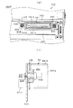
手段19.前記筐体の背面部の内側に筐体側コネクタ(筐体コネクタ811,812)を設け、
前記ユニット本体に、前記表示ユニットの前記筐体内への装着完了に伴い前記筐体側コネクタに結合されるユニット側コネクタ(面替えコネクタ841,842)を設け、
前記筐体側コネクタ及び前記ユニット側コネクタの少なくともいずれかを可動コネクタとしてコネクタ支持部材(支持体843、ねじ848及びワッシャ850)により移動可能な状態で支持し、
前記コネクタ支持部材によって、前記可動コネクタにおけるコネクタ結合方向への移動を制限し且つ同コネクタ結合方向に対して直交する方向への移動を同コネクタ支持部材との間に形成された空隙の範囲内で可能としたことを特徴とする手段1乃至手段18のいずれか1つの手段に記載の遊技機。
Means 19. A housing side connector (housing connectors 811 and 812) is provided inside the back surface of the housing,
The unit body is provided with unit-side connectors (replacement connectors 841 and 842) that are coupled to the housing-side connector when the display unit is installed in the housing.
Supporting at least one of the housing-side connector and the unit-side connector as a movable connector in a movable state by a connector support member (support body 843, screw 848 and washer 850);
The connector support member restricts movement of the movable connector in the connector coupling direction and allows movement in the direction orthogonal to the connector coupling direction within a range of a gap formed between the connector support member and the connector support member. The gaming machine according to any one of means 1 to 18, characterized in that it is made possible.

手段19によれば、絵柄表示装置をユニット本体に搭載してなる表示ユニットが筐体に対して着脱可能な構成となっており、その装着完了に伴って、筐体側と表示ユニット側にそれぞれ設けられたコネクタ同士が結合される。これにより、前記筐体側と前記表示ユニット側とが電気的に繋がった状態となる。このため、表示ユニットを装着する際に、例えば、表示ユニット側に設けられたハーネスと筐体側に設けられたハーネスとを繋げるといった別作業が不要となり、電気的な接続を容易に行うことができる。また、結合されたコネクタは表示ユニットを筐体より取り外すことで離脱するため、電気的な接続の解除も容易となる。
本手段では、前記筐体側コネクタ及び前記ユニット側コネクタの少なくともいずれかを可動コネクタとし、コネクタ支持部材によってコネクタ結合方向に対して直交する方向に移動可能な状態で取り付けている。具体的には、コネクタ支持部材と可動コネクタの間に設けられた空隙の範囲内で同可動コネクタを移動可能な構成となっている。これにより、表示ユニット装着の際には、可動コネクタが対向するコネクタに対して結合可能な位置へ移動され結合位置を合わせることができる。このため、電気的な接続、すなわち筐体側コネクタ及びユニット側コネクタが結合される際のコネクタ同士の位置調整を容易なものとすることができる。また、結合されたコネクタの離脱の際には、可動コネクタのコネクタ結合方向への移動が制限されているため、ユニット本体の引き抜きにより両コネクタが容易に分離される。可動コネクタのコネクタ結合方向への移動制限については、可動コネクタとコネクタ支持部材とがコネクタ結合方向において前後共に常時接触し当該可動コネクタの移動可能距離が全くない状態を含む以外に、可動コネクタとコネクタ支持部材とがコネクタ結合方向で製造ばらつき等に起因する僅かながたつき(クリアランス)を有し、当該可動コネクタがそのがたつき(クリアランス)の範囲内で移動可能な状態を含む。因みに、上述したクリアランスは、その寸法が可動コネクタの可動距離(範囲)に対し少なくとも1つ以上桁が小さな隙を示す。例えば、可動コネクタが上下及び左右方向に5mmの移動範囲を有する場合、上記クリアランスは0.5mm程度のものである。
According to the means 19, the display unit in which the pattern display device is mounted on the unit main body is configured to be detachable from the housing, and provided on the housing side and the display unit side when the mounting is completed. Connectors are connected to each other. As a result, the housing side and the display unit side are electrically connected. For this reason, when the display unit is mounted, for example, a separate operation of connecting a harness provided on the display unit side and a harness provided on the housing side becomes unnecessary, and electrical connection can be easily performed. . Further, since the coupled connector is detached by removing the display unit from the housing, the electrical connection can be easily released.
In this means, at least one of the housing-side connector and the unit-side connector is a movable connector, and is attached so as to be movable in a direction orthogonal to the connector coupling direction by a connector support member. Specifically, the movable connector can be moved within a gap provided between the connector support member and the movable connector. Thus, when the display unit is mounted, the movable connector can be moved to a position where it can be coupled to the opposing connector, and the coupling position can be adjusted. For this reason, electrical connection, that is, position adjustment between the connectors when the housing side connector and the unit side connector are coupled can be facilitated. Further, since the movement of the movable connector in the connector coupling direction is restricted when the coupled connector is detached, both the connectors are easily separated by pulling out the unit body. Regarding the movement limitation of the movable connector in the connector coupling direction, the movable connector and the connector other than the movable connector and the connector support member include a state where the movable connector and the connector support member are always in contact with each other in the connector coupling direction and there is no movable distance of the movable connector. This includes a state in which the support member has a slight backlash (clearance) due to manufacturing variation or the like in the connector coupling direction, and the movable connector can move within the range of the backlash (clearance). Incidentally, the clearance described above shows a gap whose dimension is small by at least one or more digits with respect to the movable distance (range) of the movable connector. For example, when the movable connector has a moving range of 5 mm vertically and horizontally, the clearance is about 0.5 mm.

手段9に示した、ユニット本体がユニット支持部材に接触した状態で表示ユニットの着脱が行われる構成との組み合わせによれば、ユニット本体をユニット支持部材に載せた状態で押し込んだり引き出したりすることで、ユニット本体着脱時の移動を安定させることができるとともに、その軌道を定常なものとすることができる。このため、ユニット本体の着脱方向に対しコネクタの結合及び離脱の方向をそろえることが可能となり、ユニット本体の押し込み動作によりコネクタが結合され、当該ユニット本体の引き出し動作によりコネクタが離脱されるように構成できる。作業者がユニット本体を押し込む際に、ユニット側コネクタの筐体側コネクタに対する結合方向を狙い定める必要が生じないことで、結合作業のための別途予備動作を必要とすることなく容易に作業を行うことができる。   According to the combination with the configuration shown in the means 9 in which the display unit is attached and detached while the unit main body is in contact with the unit support member, the unit main body is pushed and pulled out while being placed on the unit support member. The movement when the unit main body is attached / detached can be stabilized, and the trajectory can be made steady. For this reason, it is possible to align the connector coupling and detaching directions with respect to the unit body attaching / detaching direction, the connector is coupled by pushing the unit body, and the connector is detached by pulling the unit body. it can. When the operator pushes in the unit main body, it is not necessary to aim at the direction of coupling of the unit side connector to the housing side connector, so that the work can be easily performed without requiring a separate preliminary operation for the coupling work. Can do.

また、張出部により、筐体の側板と直交する方向(左右方向)への表示ユニットの位置ばらつき及び傾きを抑えることで、筐体コネクタと面替えコネクタとの筐体の側板と直交する方向(左右方向)での相対位置ばらつきを低減することができる。これにより、コネクタ同士の結合をスムーズに行うことが可能となる。   In addition, the overhanging portion suppresses the positional variation and inclination of the display unit in the direction orthogonal to the side plate of the casing (left and right direction), thereby making the direction orthogonal to the side plate of the casing of the casing connector and the surface replacement connector. Relative position variations in the (left-right direction) can be reduced. As a result, the connectors can be connected smoothly.

これら張出部及びユニット支持部材を併せ有する構成とすることで、コネクタ同士の結合を一層容易なものとすることができる。   By adopting a configuration having both the overhang portion and the unit support member, the connectors can be more easily coupled.

なお、上述の如く、可動コネクタは自身とコネクタ支持部材との間に設けられた空隙の範囲内で移動可能に構成されている。このため、両コネクタが結合された状態において表示ユニットが任意の方向、例えば上下方向や左右方向等に移動した場合でも、可動コネクタが表示ユニットの移動に合わせて移動され、外力がコネクタに集中することを抑制することができる。すなわち、コネクタの変形等の発生を抑え、繰り返しの使用にも対応することが可能となる。   As described above, the movable connector is configured to be movable within a gap provided between itself and the connector support member. For this reason, even when the display unit moves in an arbitrary direction, for example, up and down, left and right, etc. in a state where both connectors are coupled, the movable connector is moved in accordance with the movement of the display unit, and external force is concentrated on the connector. This can be suppressed. That is, it is possible to suppress the occurrence of deformation of the connector and cope with repeated use.

手段20.前記可動コネクタ及びそれを支持する前記コネクタ支持部材のいずれか一方に設けられ、前記コネクタの結合方向に延びる軸部(軸部849)と、
前記可動コネクタ及び前記コネクタ支持部材の他方に前記軸部を挿通可能に設けられ、前記軸部の外形寸法よりも大きな開口を有する開口部(丸孔846)と
を備え、
前記軸部と前記開口部との間に前記可動コネクタの移動可能範囲として前記空隙が形成されるように構成したことを特徴とする手段19に記載の遊技機。
Means 20. A shaft portion (shaft portion 849) provided in any one of the movable connector and the connector support member that supports the movable connector, and extending in the connecting direction of the connector;
An opening (round hole 846) provided so that the shaft can be inserted into the other of the movable connector and the connector support member, and having an opening larger than the outer dimension of the shaft;
The gaming machine according to claim 19, wherein the gap is formed as a movable range of the movable connector between the shaft portion and the opening portion.

手段20によれば、コネクタ支持部材及び可動コネクタのいずれか一方に設けられた軸部が他方に設けられた開口部に挿通された状態で、開口部の内面と軸部との間に空隙が形成され、開口部の内面が軸部に当接する範囲内でコネクタを移動することができる。これにより、簡易な構成で、コネクタ結合方向に対して直交する方向(以下、位置合わせ方向という)への可動コネクタの移動を好適に実現することができる。   According to the means 20, in the state where the shaft portion provided in one of the connector support member and the movable connector is inserted into the opening portion provided in the other, there is a gap between the inner surface of the opening portion and the shaft portion. The connector can be moved within the range where the inner surface of the opening is formed and abutted against the shaft. Thereby, the movement of the movable connector in a direction orthogonal to the connector coupling direction (hereinafter referred to as the alignment direction) can be suitably realized with a simple configuration.

また本手段においては、軸部及び開口部は可動コネクタの結合方向への移動制限(抜き差しの際に結合方向に生じる外力への対応)に直接かかわらない構成となっており、結合方向の移動制限と位置合わせ方向への移動規制とは互いに独立していることを特徴とする。例えば、位置合わせのため可動コネクタが移動された状態で結合がなされたとしても、その移動位置にかかわらずコネクタの引き抜きに対する負荷はほぼ同じとなり、可動コネクタの移動位置に応じてコネクタ引き抜きに対する負荷が増加するといった不都合を生じにくい。言い換えれば、コネクタの位置合わせ方向への移動を規制する部位(軸部、開口部)に対してコネクタ引き抜き作業によって生じる負荷を低減することができる。これにより、コネクタの離脱による可動コネクタの移動調整部位への影響を抑えることが可能となり、可動コネクタの繰り返し使用に対する耐久性向上に貢献できる。   Further, in this means, the shaft portion and the opening portion are configured so as not to be directly related to the movement limitation in the coupling direction of the movable connector (corresponding to the external force generated in the coupling direction at the time of insertion / extraction), and the movement limitation in the coupling direction. And the movement restriction in the alignment direction are independent of each other. For example, even if the movable connector is moved for alignment, the load for pulling out the connector is almost the same regardless of the moving position, and the load for pulling out the connector depends on the moving position of the movable connector. Inconvenient to increase. In other words, it is possible to reduce a load caused by a connector pulling operation on a portion (shaft portion or opening portion) that restricts movement of the connector in the alignment direction. Thereby, it becomes possible to suppress the influence on the movement adjustment site | part of the movable connector by the detachment | leave of a connector, and it can contribute to the durability improvement with respect to repeated use of a movable connector.

手段21.前記ユニット本体は、前記側壁部に加え、奥壁部及び上壁部を少なくとも有し、これら壁部により囲まれた収容空間内に、前記絵柄表示装置を収容するものであり、
前記ユニット本体の側壁部は、当該ユニット本体の内外に貫通し、且つ少なくとも前記張出部の後端部を視認可能な窓部(開口部450,451)を有することを特徴とする手段1乃至手段20のいずれか1つの手段に記載の遊技機。
Means 21. The unit main body has at least a back wall portion and an upper wall portion in addition to the side wall portion, and accommodates the pattern display device in a housing space surrounded by these wall portions,
The side wall of the unit main body has windows (openings 450 and 451) that penetrate the inside and outside of the unit main body and at least allow the rear end of the overhanging portion to be visually recognized. The gaming machine according to any one of means 20.

手段21によれば、ユニット本体は、絵柄表示装置の奥側に奥壁部、絵柄表示装置の上側に上壁部を有し、これら奥壁部及び上壁部は左右の両側壁部と連結している。すなわち、ユニット本体は筐状をなす構成となっている。ユニット本体の側壁部に内外に貫通する窓部を設けたことで、当該窓部を通して張出部の後方に形成される死角となる空間を視認することができる。このため、仮にその死角となる空間に不正基板等が設置されたとしても、表示ユニットを装着した状態のまま(前面扉を備える場合は同前面扉を開放した状態で)、遊技機の斜め前方からそれら不正基板等の有無を容易に確認でき、不正基板等の発見が遅れるといった不都合を回避することが可能となる。   According to the means 21, the unit main body has a back wall part on the back side of the picture display device and an upper wall part on the top side of the picture display device, and the back wall part and the top wall part are connected to the left and right side wall parts. doing. That is, the unit main body has a casing shape. By providing a window portion penetrating inward and outward in the side wall portion of the unit main body, a space serving as a blind spot formed behind the projecting portion can be visually recognized through the window portion. For this reason, even if an illegal board is installed in the blind spot, the display unit is still attached (if the front door is provided, the front door is opened) and the game machine is diagonally forward. Therefore, it is possible to easily confirm the presence or absence of the illegal substrate and the like, and to avoid the disadvantage that the discovery of the illegal substrate or the like is delayed.

また、例えば筐体側に設置された不正基板から表示ユニット側(特に主制御装置)に配線等が延設される場合、ユニット本体が筐状であるために、配線を挿通可能な場所が限定される。本手段においては、上述した内外に貫通している窓部が配線の挿通に利用される可能性があるが、窓部を視認以外の目的、特に配線等の取り回しに使用しないことで、上述のごとく窓部を介して表示ユニットの内部に挿通された配線の発見は非常に容易となる。   Also, for example, when wiring etc. is extended from the unauthorized board installed on the housing side to the display unit side (particularly the main control device), the place where the wiring can be inserted is limited because the unit main body has a housing shape. The In this means, there is a possibility that the window portion penetrating the inside and outside described above may be used for the insertion of the wiring, but by not using the window portion for purposes other than visual recognition, in particular, for the wiring and the like, Thus, it is very easy to find the wiring inserted into the display unit through the window.

なお、奥壁部及び上壁部の表面(特に外面)には、リブ等の凹凸が設けられてもよい。   In addition, irregularities such as ribs may be provided on the surfaces (particularly the outer surface) of the back wall portion and the upper wall portion.

手段22.少なくとも前記絵柄表示装置における変動停止絵柄に対応して行われる補助演出を表示する補助表示装置(液晶表示装置711)と、前記補助表示装置に対して補助演出情報を出力する補助演出制御装置(表示制御装置730)とを前記表示ユニットに搭載したことを特徴とする手段1乃至手段21のいずれか1つの手段に記載の遊技機。   Means 22. An auxiliary display device (liquid crystal display device 711) that displays an auxiliary effect performed in response to at least a change stop picture in the picture display device, and an auxiliary effect control device (display) that outputs auxiliary effect information to the auxiliary display device The gaming machine according to any one of the means 1 to 21, wherein a control device 730) is mounted on the display unit.

手段22によれば、表示ユニットに補助表示装置及び補助演出制御装置を搭載することで、表示ユニットの交換時には絵柄表示装置、主制御装置、補助表示装置及び補助演出制御装置をまとめて交換できる。つまり遊技機ごとに固有となる構成を、それ以外と区別しつつまとめて交換できる。故に、表示ユニットを交換することで遊技機の機種変更が容易に実施できるようになる。   According to the means 22, by mounting the auxiliary display device and the auxiliary effect control device on the display unit, the pattern display device, the main control device, the auxiliary display device and the auxiliary effect control device can be exchanged together when the display unit is replaced. In other words, the configurations unique to each gaming machine can be exchanged together while distinguishing them from the others. Therefore, it is possible to easily change the model of the gaming machine by exchanging the display unit.

なお、変動停止絵柄に対応して行われる補助演出とは、毎回の遊技において、絵柄表示装置にて停止可能となる停止絵柄が抽選や遊技回数等により決定される場合に、その停止絵柄が実際に停止表示される前若しくは後、又は停止表示されると同時に、絵柄表示装置にて停止可能となる停止絵柄に対応して行われる補助演出、遊技者の操作に伴い決定される補助演出等を示す。また、それら補助演出は、抽選等により決定された絵柄そのものを(絵柄に一致して)示す表示演出、抽選等で決定された絵柄を示唆する表示演出等を含む。「絵柄を示唆する表示演出」には、例えば抽選結果が外れの場合に同抽選結果が大当たりであるかも知れないことをほのめかす演出や、抽選結果が大当たりである場合に同抽選結果が外れである可能性があることを示す演出を含む。因みに、上述した「遊技者の操作」とは、複数の絵柄が停止可能となる場合にいずれかの絵柄を選択して停止させる操作や、複数設定されている演出のうちいずれかを選択する操作等を含む。   In addition, the auxiliary effect performed in response to the variable stop pattern means that the stop pattern is actually used when the stop pattern that can be stopped by the pattern display device is determined by lottery or the number of games in each game. Before or after the stop display, or at the same time as the stop display, an auxiliary effect performed in response to the stop picture that can be stopped by the picture display device, an auxiliary effect determined in accordance with the player's operation, etc. Show. The auxiliary effects include a display effect indicating the pattern itself determined by lottery or the like (in accordance with the pattern), a display effect suggesting the pattern determined by the lottery, or the like. In the “display effect that suggests a pattern”, for example, an effect that hints that the lottery result may be a big win if the lottery result is out, or the lottery result is out if the lottery result is a big hit Includes an indication that there is a possibility. Incidentally, the above-mentioned “player operation” refers to an operation to select and stop any of the designs when a plurality of designs can be stopped, or an operation to select one of the set effects. Etc.

手段23.手段1乃至手段22のいずれか1つの手段において、遊技機は、遊技媒体としてのメダルの投入(クレジットされた仮想メダルの投入を含む)と遊技者による所定の始動操作とを契機として前記絵柄表示装置の前記周回体の回転を開始するとともに、遊技者による所定の停止操作に前記周回体の変動を停止し、その回転停止時において表示窓(下側視認窓22)より視認できる停止絵柄に応じて遊技者に利益状態を付与する遊技機であること。   Means 23. In any one of the means 1 to 22, the gaming machine displays the picture display in response to insertion of a medal as a game medium (including insertion of a credited virtual medal) and a predetermined starting operation by the player. According to the stop pattern that can be visually recognized from the display window (lower viewing window 22) when the rotation of the device starts and stops the change of the circuit in a predetermined stop operation by the player. And a gaming machine that gives a profit state to the player.

上述した各手段は、一般にスロットマシンと称される遊技機として好適に具体化できる。この遊技機は、絵柄表示装置及び制御装置を備えた表示ユニットの交換により機種変更が行われる。かかる場合に、上記のごとく表示ユニットを着脱する際の作業性を担保しつつ筐体内における不正基板等を設置可能な空間の低減が可能となれば、技術的貢献度は大きいものとなる。   Each means mentioned above can be suitably embodied as a gaming machine generally called a slot machine. This gaming machine is changed in model by exchanging a display unit having a picture display device and a control device. In such a case, the technical contribution will be great if it is possible to reduce the space in which the illegal substrate etc. can be installed in the housing while ensuring the workability when the display unit is attached and detached as described above.

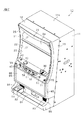
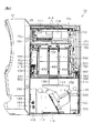
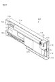
以下、遊技機の一種である回胴式遊技機、具体的にはスロットマシンに適用した場合の一実施の形態を、図面に基づいて詳細に説明する。図1はスロットマシン10の全体構成を示す斜視図、図2はスロットマシン10の正面図、図3はスロットマシン10の側面図、図4は前面扉12を開いた状態のスロットマシン10の斜視図である。本スロットマシン10では、内側扉700を有する面替えユニット400をスロットマシン10の内部に備える構成となっている。図5は、前面扉12と内側扉700とを開いた状態の正面斜視図であり、図6は前面扉12と内側扉700とを開いた状態の正面図である。これら図1〜図6に基づいて、スロットマシン10の構成について詳しく説明する。なお、以下の説明において、特に指示しない限りはスロットマシン10の正面視を基準に上下左右等の方向を特定することとする。   Hereinafter, an embodiment in the case of application to a spinning cylinder type gaming machine, which is a kind of gaming machine, specifically, a slot machine will be described in detail with reference to the drawings. 1 is a perspective view showing the overall configuration of the slot machine 10, FIG. 2 is a front view of the slot machine 10, FIG. 3 is a side view of the slot machine 10, and FIG. 4 is a perspective view of the slot machine 10 with the front door 12 open. FIG. In the slot machine 10, a surface changing unit 400 having an inner door 700 is provided inside the slot machine 10. FIG. 5 is a front perspective view of the state in which the front door 12 and the inner door 700 are opened, and FIG. 6 is a front view of the state in which the front door 12 and the inner door 700 are opened. The configuration of the slot machine 10 will be described in detail with reference to FIGS. In the following description, unless otherwise specified, directions such as up, down, left and right are specified based on the front view of the slot machine 10.

(筐体11の外観構成)
スロットマシン10は、その外殻を形成する筐体11を備えている。筐体11は、木製板状に形成された天板11a、底板11b、背板11c、左側板11d及び右側板11eからなり(図8の筐体斜視図参照)、隣接する各板11a〜11eが接着等の固定手段によって固定されることにより、全体として前面側が開放された箱状に形成されている。なお、各板11a〜11eは木製のパネルによって構成される以外に、合成樹脂製パネル又は金属製パネルによって構成されてもよいし、合成樹脂材料又は金属材料によって一体の箱状に形成されてもよい。また、各板11a〜11eは、内外に貫通した開口部やリブ等による凹凸を有する構成であってもよい。以上のように構成された筐体11は、遊技ホールへの設置の際にいわゆる島設備に対し釘を打ち付ける等して取り付けられる。
(External configuration of the casing 11)
The slot machine 10 includes a housing 11 that forms an outer shell thereof. The casing 11 includes a top plate 11a, a bottom plate 11b, a back plate 11c, a left side plate 11d, and a right side plate 11e formed in a wooden plate shape (see the perspective view of the case in FIG. 8), and adjacent plates 11a to 11e. Is fixed by fixing means such as adhesion, so that it is formed in a box shape whose front side is opened as a whole. In addition, each board 11a-11e may be comprised with a synthetic resin panel or a metal panel other than being comprised with a wooden panel, or even if it is formed in the integral box shape with a synthetic resin material or a metal material. Good. Moreover, the structure which has the unevenness | corrugation by the opening part which penetrated inside and outside, a rib, etc. may be sufficient as each board 11a-11e. The casing 11 configured as described above is attached by, for example, driving nails against a so-called island facility at the time of installation in the game hall.

(前面扉12の説明)
筐体11の前面側には、前面開閉扉としての前面扉12が開閉可能に取り付けられている。前面扉12は、筐体11の前側開放部を全て塞ぐように設けられ、スロットマシン10の左縁部を軸線として手前側に開放されるようになっている。また、前面扉12の周縁部には、筐体11の左右両側板及び天板及び底板における前端面に近接するように張り出した張出部15が設けられている。
(Description of front door 12)
A front door 12 as a front open / close door is attached to the front side of the housing 11 so as to be openable and closable. The front door 12 is provided so as to block all of the front opening portion of the housing 11, and is opened to the front side with the left edge portion of the slot machine 10 as an axis. In addition, a protruding portion 15 that protrudes so as to be close to the front end surfaces of the left and right side plates, the top plate, and the bottom plate of the housing 11 is provided at the peripheral portion of the front door 12.

前面扉12の上半部には、正面に向けて上下に上側視認窓21と下側視認窓22とが並設されている。これら視認窓21,22には、透明な板材よりなりかつ視認窓21,22とほぼ同形状をなす透明パネル23,24(図8参照)が設けられている。それら透明パネル23,24は、ビス等の締結具(図示略)により前面扉12の背面側に固定されている。本実施の形態おいては特に、透明パネル23,24が1枚板で構成されている。   In the upper half of the front door 12, an upper viewing window 21 and a lower viewing window 22 are arranged in parallel up and down toward the front. The viewing windows 21 and 22 are provided with transparent panels 23 and 24 (see FIG. 8) made of a transparent plate material and having substantially the same shape as the viewing windows 21 and 22. The transparent panels 23 and 24 are fixed to the back side of the front door 12 with fasteners (not shown) such as screws. In the present embodiment, in particular, the transparent panels 23 and 24 are constituted by a single plate.

これら透明パネル23,24を介して前面扉12の後方が視認可能である。換言すれば、前面扉12の後方に設けられる装飾絵柄や後述する液晶図柄等が視認窓21,22を通じて視認可能となっている。   The rear of the front door 12 is visible through these transparent panels 23 and 24. In other words, a decorative pattern provided behind the front door 12 and a liquid crystal pattern, which will be described later, can be viewed through the viewing windows 21 and 22.

前面扉12の前面側において、上縁部及び左右両縁部には、視認窓21,22を囲む囲い部25が透明パネル23,24よりも前方に張り出すように形成されている。また、その囲い部25の上部には、遊技状況に応じたランプ演出を行うための中央ランプ部26が設けられている。   On the front side of the front door 12, an enclosure 25 surrounding the viewing windows 21 and 22 is formed on the upper edge and the left and right edges so as to protrude forward from the transparent panels 23 and 24. In addition, a central lamp portion 26 for performing a lamp effect according to the game situation is provided on the upper portion of the enclosure portion 25.

下側視認窓22の下方は、遊技者により操作される各種操作部材等を配備した操作部となっており、メダル投入装置30と、MAXベットスイッチ40及び1ベットスイッチ41と、スタートレバー45と、ストップスイッチ50〜52と、精算スイッチ55と、返却スイッチ60とが配備されている。以下、各構成部品を個々に説明する。   Below the lower viewing window 22 is an operation unit provided with various operation members operated by a player, a medal insertion device 30, a MAX bet switch 40, a 1 bet switch 41, a start lever 45, Stop switches 50 to 52, a settlement switch 55, and a return switch 60 are provided. Hereinafter, each component will be described individually.

メダル投入装置30は、下側視認窓22の下方右側に設けられており、同メダル投入装置30の投入口より投資価値としてのメダルが1枚ずつ投入される。メダル投入装置30は投資価値を入力する入力手段を構成し、メダル投入装置30が遊技者によるメダルの直接投入という動作を伴う点に着目すれば、投資価値を直接入力する直接入力手段を構成するものといえる。   The medal insertion device 30 is provided on the lower right side of the lower viewing window 22, and medals as investment values are inserted one by one from the insertion port of the medal insertion device 30. The medal insertion device 30 constitutes an input means for inputting an investment value, and if attention is paid to the point that the medal insertion device 30 involves an operation of direct insertion of a medal by a player, a direct input means for directly inputting the investment value is constituted. It can be said that.

メダル投入装置30から投入されたメダルは、前面扉12の背面に設けられた通路切換手段に送られる。すなわち、前面扉12の背面には、通路切換手段としてのセレクタ31が設けられており、メダル投入装置30から投入されたメダルは、セレクタ31によって貯留用通路32か排出用通路33のいずれかに導かれる(図4参照)。セレクタ31にはメダル通路切換ソレノイドが設けられており、そのメダル通路切換ソレノイドの非励磁時にはメダル通路が排出用通路33側とされ、励磁時には貯留用通路32側に切り換えられる。この場合、貯留用通路32に導かれたメダルは、ホッパ装置110へと導かれる。一方、排出用通路33に導かれたメダルは、前面扉12の前面下部に設けられたメダル排出口34からメダル受皿81へと導かれ、遊技者に返却される。   The medals inserted from the medal insertion device 30 are sent to the passage switching means provided on the back surface of the front door 12. That is, a selector 31 as a passage switching means is provided on the rear surface of the front door 12, and medals inserted from the medal insertion device 30 are placed in either the storage passage 32 or the discharge passage 33 by the selector 31. Guided (see FIG. 4). The selector 31 is provided with a medal path switching solenoid. When the medal path switching solenoid is not excited, the medal path is set to the discharge path 33 side, and when excited, the medal path switching solenoid is switched to the storage path 32 side. In this case, the medal guided to the storage passage 32 is guided to the hopper device 110. On the other hand, the medal guided to the discharge passage 33 is guided to the medal tray 81 from the medal discharge port 34 provided in the lower front portion of the front door 12 and returned to the player.

下側視認窓22の下方左側にはボタン状のMAXベットスイッチ40が設けられており、同MAXベットスイッチ40の押し操作によって、クレジットされた仮想メダルを一度に3枚投入することができる。MAXベットスイッチ40の左方には同MAXベットスイッチ40よりも小さなボタン状の1ベットスイッチ41が設けられている。1ベットスイッチ41が押し操作されることで仮想メダルが一度に1枚投入される。各ベットスイッチ40,41は、前記メダル投入装置30とともに投資価値を入力する入力手段を構成する。また、メダル投入装置30が遊技者によるメダルの直接投入という動作を伴うのに対し、各ベットスイッチ40,41は、クレジットに基づく仮想メダルの投入という動作を伴うに過ぎない点に着目すれば、投資価値を間接入力する間接入力手段を構成するものともいえる。   A button-like MAX bet switch 40 is provided on the lower left side of the lower viewing window 22, and by pressing the MAX bet switch 40, three credited virtual medals can be inserted at a time. A button-like 1-bet switch 41 smaller than the MAX bet switch 40 is provided on the left side of the MAX bet switch 40. By pressing the 1-bet switch 41, one virtual medal is inserted at a time. Each bet switch 40, 41 constitutes an input means for inputting an investment value together with the medal insertion device 30. Further, if the medal insertion device 30 is accompanied by an operation of direct insertion of medals by a player, the bet switches 40 and 41 are only accompanied by an operation of insertion of virtual medals based on credits. It can be said that it constitutes an indirect input means for indirectly inputting the investment value.

なお、MAXベットスイッチ40には、1遊技回につき投入できるメダル最大数(3枚)に達していないことを遊技者に知らせるために、図示しない発光部材としてのランプが内蔵されている。当該ランプは、MAXベットスイッチ40のスイッチ操作が有効である状況時において点灯されて当該スイッチ40の操作を促すが、クレジットされた仮想メダルが存在しない場合や既に3枚のメダル投入がなされている状況下では消灯される。ここで、上記点灯に代えて、点滅させてメダル投入の促しを遊技者に一層分かり易くしてもよい。   Note that the MAX bet switch 40 has a built-in lamp as a light emitting member (not shown) in order to notify the player that the maximum number of medals that can be inserted per game (three) has not been reached. The lamp is turned on in a situation where the switch operation of the MAX bet switch 40 is valid and prompts the operation of the switch 40. However, when there is no credited virtual medal, or three medals have already been inserted. Turns off under circumstances. Here, instead of the above-described lighting, the player may make it easier to understand the prompt for medal insertion by blinking.

MAXベットスイッチ40の下側にはスタートレバー45が設けられている。このスタートレバー45は、後述するリール装置650の各リール(回転体)655〜657を回転始動させるための操作部材であり、各リール655〜657を回転開始、すなわち可変表示を開始させるべく操作される開始操作手段又は始動操作手段を構成する。   A start lever 45 is provided below the MAX bet switch 40. The start lever 45 is an operation member for starting rotation of each reel (rotating body) 655 to 657 of the reel device 650 described later, and is operated to start rotation of each reel 655 to 657, that is, to start variable display. Start operation means or start operation means.

スタートレバー45の右側には、ボタン状の3つのストップスイッチ50〜52が左右に並設されている。各ストップスイッチ50〜52は、停止対象となるリール655〜657(左、中、右の三列のリール)に対応するよう設けられており、回転中の各リール655〜657を個別に停止させるために操作される停止操作手段を構成する。各ストップスイッチ50〜52は、各リール655〜657が定速回転となると停止させることが可能な状態となり、かかる状態中には図示しないランプが点灯表示されることによって停止操作が可能であることが報知され、回転が停止すると消灯されるようになっている。   On the right side of the start lever 45, three button-like stop switches 50 to 52 are arranged side by side. Each of the stop switches 50 to 52 is provided so as to correspond to the reels 655 to 657 (three columns of left, middle, and right) to be stopped, and individually stops the reels 655 to 657 that are rotating. Therefore, stop operation means operated for the purpose is configured. Each of the stop switches 50 to 52 can be stopped when the reels 655 to 657 are rotated at a constant speed, and a stop operation can be performed by lighting a lamp (not shown) during such a state. Is notified, and is turned off when the rotation stops.

スタートレバー45左側には、ボタン状の精算スイッチ55が設けられている。すなわち、本スロットマシン10では、所定の最大値(例えばメダル50枚分)となるまでの余剰の投入メダルや入賞時の獲得メダルをクレジットメダルとして貯留記憶するクレジット機能を有しており、クレジットメダルが貯留記憶されている状態で精算スイッチ55が押下操作されることで、クレジットメダルが現実のメダルとして払い出される。この場合、クレジットされた仮想メダルを現実のメダルとして払い出すという機能に着目すれば、精算スイッチ55は貯留記憶された遊技価値を実際に払い出すための精算操作手段を構成するものともいえる。   On the left side of the start lever 45, a button-like settlement switch 55 is provided. That is, the slot machine 10 has a credit function for storing and storing surplus inserted medals up to a predetermined maximum value (for example, 50 medals) or winning medals as credit medals. The credit medal is paid out as an actual medal by depressing the settlement switch 55 in a state where is stored and stored. In this case, if paying attention to the function of paying out the credited virtual medal as an actual medal, it can be said that the checkout switch 55 constitutes a checkout operation means for actually paying out the stored game value.

なお、所定の最大値(例えばメダル50枚分)となるまでの余剰の投入メダルや入賞時の獲得メダルをクレジットメダルとして貯留記憶するように設定された「クレジットモード」と、余剰の投入メダルや入賞時の獲得メダルを現実のメダルとして払い出すように設定された「ダイレクトモード」とを切換可能としたスロットマシンの場合には、前記精算スイッチ55に、モード切換のための切換スイッチとしての機能を付加しても良い。この場合、精算スイッチ(切換スイッチ)55は、1度押されるとオン状態になり、もう1度押されるとオフ状態になり、その後押下操作が行われるごとにオンオフが切り替わるように構成される。そして、精算スイッチ55がオン状態のときにはクレジットモードとされ、精算スイッチ55がオフ状態のときにはダイレクトモードとされる。クレジットモードからダイレクトモードに切り換えられた際にクレジットメダルがある場合には、その分のクレジットメダルが現実のメダルとして払い出される。これにより、遊技者はクレジットモードとダイレクトモードとを切り換えることで自身の好みに応じた形式で遊技を実行することができる。かかる精算スイッチ55は投入価値及び遊技価値の取扱形式を切り換える切換操作手段を構成する。   It should be noted that the surplus inserted medals up to a predetermined maximum value (for example, 50 medals) or the “credit mode” set to store and memorize the winning medals as a credit medal, the surplus inserted medals, In the case of a slot machine that can switch between the “direct mode” set so that the winning medal at the time of winning is paid out as an actual medal, the settlement switch 55 has a function as a switching switch for mode switching. May be added. In this case, the settlement switch (switch) 55 is turned on when pressed once, turned off when pressed again, and turned on / off every time a pressing operation is performed thereafter. When the settlement switch 55 is on, the credit mode is selected. When the settlement switch 55 is off, the direct mode is selected. If there is a credit medal when the credit mode is switched to the direct mode, the corresponding credit medal is paid out as an actual medal. Thereby, the player can execute the game in a format according to his / her preference by switching between the credit mode and the direct mode. The settlement switch 55 constitutes a switching operation means for switching the input value and game value handling formats.

メダル投入装置30の下側(ストップスイッチ52の左側)には、ボタン状の返却スイッチ60が設けられている。返却スイッチ60は、メダル投入装置30に投入されたメダルがセレクタ31内に詰まった際に押されるスイッチであり、このスイッチ60が押されることによりセレクタ31が機械的に連動して動作され、同セレクタ31内に詰まったメダルがメダル排出口34より返却されるようになっている。   A button-like return switch 60 is provided below the medal insertion device 30 (on the left side of the stop switch 52). The return switch 60 is a switch that is pressed when a medal inserted into the medal insertion device 30 is jammed in the selector 31. When the switch 60 is pressed, the selector 31 is mechanically interlocked to operate. A medal jammed in the selector 31 is returned from the medal discharge port 34.

返却スイッチ60の右側で前面扉12の右端側には、同前面扉12の背後に貫通するキー孔70が設けられており、そのキー孔70には扉背面側からキーシリンダ71が設けられている。このキーシリンダ71は、前面扉12を開放するために操作される施錠装置を構成するものである。但し、施錠装置の詳細は後述する。   A key hole 70 penetrating behind the front door 12 is provided on the right end side of the front door 12 on the right side of the return switch 60, and a key cylinder 71 is provided in the key hole 70 from the back side of the door. Yes. The key cylinder 71 constitutes a locking device that is operated to open the front door 12. However, details of the locking device will be described later.

ストップスイッチ50〜52の下方には、機種名や遊技に関わるキャラクタなどが表示された下部プレート80が装着され、更にその下方にはメダル受皿81が設けられている。メダル受皿81には、メダル排出口34を介してスロットマシン内部のホッパ装置110等からメダルが排出される。メダル排出口34の左右にはスピーカ部82,83が設けられおり、メダル受皿81の左方(左側のスピーカ部82の前側)には、手前側下方に反転可能な灰皿84が設けられている。   Below the stop switches 50 to 52, a lower plate 80 on which a model name, a character related to a game, and the like are displayed is mounted, and a medal tray 81 is provided below the lower plate 80. To the medal tray 81, medals are discharged from the hopper device 110 or the like inside the slot machine through the medal discharge port 34. Speaker units 82 and 83 are provided on the left and right sides of the medal discharge port 34, and an ashtray 84 that can be reversed to the front side is provided on the left side of the medal tray 81 (the front side of the left speaker unit 82). .

遊技に際しては、中央ランプ部26やスピーカ部82,83により、その都度の遊技状況に応じたランプ演出や音声演出等が行われる。すなわち、中央ランプ部26による発光色や発光パターンを適宜変更したり、スピーカ部82,83による音声パターンを適宜変更したりすることで、役の成立等が遊技者に告知される。また、これら中央ランプ部26及びスピーカ部82,83を用いて、エラー告知等を行うことも可能である。   When playing a game, the center lamp unit 26 and the speaker units 82 and 83 perform lamp effects, sound effects, and the like according to the game situation each time. In other words, the player is notified of the establishment of the combination by appropriately changing the light emission color or light emission pattern by the central lamp unit 26 or by appropriately changing the sound pattern by the speaker units 82 and 83. In addition, error notification or the like can be performed using the central lamp unit 26 and the speaker units 82 and 83.

前面扉12の下部には、囲い部25に連続するような造形が施されており、メダル受皿81及び灰皿84の上方の左右両側は側壁部85となっている。側壁部85には切欠部86が設けられている。例えば、スロットマシン10の側方にメダル貸出装置が設置され、該メダル貸出装置からメダル供給ノズル等が延出される場合、切欠部86にメダル供給ノズルが配され、このノズルを介してメダル受皿81にメダルが貸出供給される。これにより、遊技に際しノズルが邪魔になる、貸出メダルがこぼれ落ちる等の不都合が解消される。   The lower part of the front door 12 is shaped so as to be continuous with the enclosure part 25, and the left and right sides above the medal tray 81 and the ashtray 84 are side wall parts 85. The side wall 85 is provided with a notch 86. For example, when a medal lending device is installed on the side of the slot machine 10 and a medal supply nozzle or the like is extended from the medal lending device, a medal supply nozzle is disposed in the notch 86, and a medal tray 81 is provided via this nozzle. The medals will be lent out. As a result, inconveniences such as a nozzle being in the way of a game and renting out medals are eliminated.

(筐体11の内部構造)
次に、スロットマシン10の内部構造について説明する。先ずは、筐体11の内部構造について図8,図9を用いて説明する。図8は、筐体11の内部構造を示す斜視図、図9は同内部構造を示す正面図である。
(Internal structure of housing 11)
Next, the internal structure of the slot machine 10 will be described. First, the internal structure of the housing 11 will be described with reference to FIGS. FIG. 8 is a perspective view showing the internal structure of the housing 11, and FIG. 9 is a front view showing the internal structure.

図8及び図9に示すように、筐体11の内部において下側の左隅部には電源ボックス100が設けられている。電源ボックス100は、各種電気装置や制御装置等に電源を供給するための電源装置であり、起動スイッチである電源スイッチ101や、スロットマシン10の各種状態をリセットするためのリセットスイッチ102、ホール管理者などがメダルの出玉調整を行うための設定キー挿入孔103などを備えている。また、本スロットマシン10は各種データのバックアップ機能を有しており、万一停電が発生した際でも停電時の状態を保持し、停電からの復帰(復電)の際には停電時の状態に復帰できるようになっている。この場合、例えば遊技ホールの営業が終了する場合のように通常手順で電源を遮断すると遮断前の状態が記憶保持されるが、リセットスイッチ102を押しながら電源スイッチをオンすると、バックアップデータがリセットされるようになっている。一方、電源スイッチ101がオンされている状態でリセットスイッチ102を押した場合には、エラー状態がリセットされる。また、ホール管理者等が設定キー挿入孔103へ設定キーを挿入して操作することにより、スロットマシン10の設定状態(当選確率)を「設定1」から「設定6」まで変更できるようになっている。   As shown in FIGS. 8 and 9, a power supply box 100 is provided in the lower left corner of the housing 11. The power supply box 100 is a power supply device for supplying power to various electric devices, control devices, and the like. The power switch 101 as a start switch, a reset switch 102 for resetting various states of the slot machine 10, and hall management A setting key insertion hole 103 or the like is provided for a person or the like to adjust the appearance of medals. In addition, this slot machine 10 has a backup function of various data, and maintains the state at the time of power failure even if a power failure occurs, and the state at the time of power failure at the time of recovery from power failure (power recovery) You can return to. In this case, for example, when the game hall is closed, when the power is turned off in the normal procedure, the state before the turn-off is stored and retained. However, if the power switch is turned on while pressing the reset switch 102, the backup data is reset. It has become so. On the other hand, when the reset switch 102 is pressed while the power switch 101 is on, the error state is reset. Further, the setting state (winning probability) of the slot machine 10 can be changed from “setting 1” to “setting 6” by inserting a setting key into the setting key insertion hole 103 and operating by the hole manager or the like. ing.

筐体11の内部において電源ボックス100の右側には、メダルを遊技者に付与する払出手段としてのホッパ装置110が設置されている。ホッパ装置110は、多数枚のメダルを貯留可能な合成樹脂製の貯留タンク111と、貯留タンク111内のメダルを順次払い出す払出装置112とより構成されている。払出装置112は、図示しないメダル払出用回転板を回転させることにより、排出用通路33の中央右部に設けられた開口113へメダルを排出し、排出用通路33を介してメダル受け皿81へメダルを払い出すようになっている。貯留タンク111は、上面開口部がほぼ正方形状をなし、下面が斜め下方に傾斜している。また、貯留タンク111には、タンク隅部にメダル排出孔114が形成されており、そのメダル排出孔114には金属製の誘導プレート115が取り付けられている。   A hopper device 110 is installed on the right side of the power supply box 100 inside the housing 11 as a payout means for giving medals to the player. The hopper device 110 includes a synthetic resin storage tank 111 that can store a large number of medals, and a payout device 112 that sequentially pays out medals in the storage tank 111. The payout device 112 rotates a medal payout rotating plate (not shown) to discharge the medal to the opening 113 provided in the central right part of the discharge passage 33 and to the medal tray 81 through the discharge passage 33. To come out. The storage tank 111 has a substantially square upper surface opening and a lower surface inclined obliquely downward. The storage tank 111 has a medal discharge hole 114 formed at a corner of the tank, and a metal guide plate 115 is attached to the medal discharge hole 114.

筐体11の内部においてホッパ装置110の右方には、貯留タンク111内に所定量以上のメダルが貯留されることを回避するための予備タンク120が設けられている。貯留タンク111に多数のメダルが貯まり、その高さが、誘導プレート115が設けられた高さ以上になると、かかる余剰メダルが誘導プレート115により予備タンク120に導かれ、当該予備タンク120内で貯留されることとなる。   A reserve tank 120 is provided on the right side of the hopper device 110 inside the housing 11 to avoid storing a predetermined amount or more of medals in the storage tank 111. When a large number of medals are stored in the storage tank 111 and the height is equal to or higher than the height at which the guide plate 115 is provided, the surplus medals are guided to the reserve tank 120 by the guide plate 115 and stored in the reserve tank 120. Will be.

筐体11の背板11cには、貯留タンク111の上方位置に四角形状をなす孔部130が形成されている。この孔部130を介して、筐体外部から筐体内部に通じるメダル補給通路を設置することができるようになっており、メダル補給通路の設置により貯留タンク111へのメダルの自動補給が実現できるようになっている。なお、図7等では、孔部130が開放された状態を示しているが、孔部130を使用しない場合(メダルの自動補給を行わない場合等)には、孔部130は塞がれた状態となっている。但し、孔部130が塞がれた状態では、同孔部130が容易に開放できるよう孔部130周囲に切欠が設けられているとよい。   In the back plate 11 c of the housing 11, a rectangular hole 130 is formed at an upper position of the storage tank 111. Through this hole portion 130, a medal replenishment passage that leads from the outside of the housing to the inside of the housing can be installed, and automatic replenishment of medals to the storage tank 111 can be realized by installing the medal replenishment passage. It is like that. 7 and the like show a state in which the hole 130 is opened, but the hole 130 is closed when the hole 130 is not used (for example, when automatic replenishment of medals is not performed). It is in a state. However, when the hole 130 is closed, a notch is preferably provided around the hole 130 so that the hole 130 can be easily opened.

背板11cには、孔部130の上方位置(後述する面替えユニット400の後方)に横長の通気孔140が複数形成されている。これらの通気孔140を介して、筐体11内の熱を帯びた空気を外部に排出することができる。なお、通気孔140は、背板11cの上部又は下部に形成されてもよいし、各側板11d,11e又は天板11aに形成されてもよい。   A plurality of horizontally long vent holes 140 are formed in the back plate 11c above the hole 130 (behind the surface changing unit 400 described later). Through these vent holes 140, the heated air in the housing 11 can be discharged to the outside. The vent hole 140 may be formed in the upper part or the lower part of the back plate 11c, or may be formed in each side plate 11d, 11e or the top plate 11a.

筐体11の左側板11dには、筐体11の開口内周縁に沿って長尺状の扉支持金具200がビス等の締結具(図示略)により固定されている。扉支持金具200の上下2カ所には、支軸201,202が設けられており、各支軸201,202は上方に延びる先細り形状の軸部を有する。この扉支持金具200によって、前面扉12が回動可能に支持されるようになっている。   A long door support fitting 200 is fixed to the left side plate 11d of the casing 11 along the inner peripheral edge of the opening of the casing 11 by a fastener (not shown) such as a screw. Support shafts 201 and 202 are provided at two upper and lower portions of the door support fitting 200, and each of the support shafts 201 and 202 has a tapered shaft portion extending upward. The front door 12 is rotatably supported by the door support metal 200.

すなわち、図5に示すように、前記前面扉12には、各支軸201,202に対応してそれら支軸201,202の軸部が挿入される挿入孔を備えた支持金具211,212が設けられている。そして、各支軸201,202の上方に支持金具211,212を配置させた上で前面扉12を降下させることにより、支持金具211,212の挿入孔に支軸201,202の軸部が挿入された状態とされる。これにより、前面扉12は、筐体11に対して両支軸201,202を結ぶ上下方向へ延びる開閉軸線を中心として回動可能に支持され、その回動によって筐体11の前面開放側を開放したり閉鎖したりすることができるように構成されている。   That is, as shown in FIG. 5, the front door 12 has support brackets 211 and 212 having insertion holes into which the shaft portions of the support shafts 201 and 202 are inserted corresponding to the support shafts 201 and 202, respectively. Is provided. Then, the support brackets 211 and 212 are arranged above the respective support shafts 201 and 202, and then the front door 12 is lowered, whereby the shaft portions of the support shafts 201 and 202 are inserted into the insertion holes of the support fittings 211 and 212. It is assumed that it was done. As a result, the front door 12 is supported so as to be rotatable about an opening / closing axis line extending in the vertical direction connecting the both support shafts 201 and 202 with respect to the casing 11, and the front opening side of the casing 11 is supported by the rotation. It is configured so that it can be opened or closed.

筐体11の右側板11eには、筐体11の開口内周縁に沿って長尺状の鉤受け金具220がビス等の締結具(図示略)により固定されている。また、鉤受け金具220の上下2カ所には、前面扉12を閉鎖状態で保持するための鉤受け部221,222が設けられている。この鉤受け金具220によって、前面扉12が筐体11に閉止された状態で保持される。   On the right side plate 11 e of the housing 11, a long hook metal fitting 220 is fixed by a fastener (not shown) such as a screw along the inner peripheral edge of the opening of the housing 11. In addition, hook receiving portions 221 and 222 for holding the front door 12 in a closed state are provided at two upper and lower portions of the hook receiving metal 220. The front door 12 is held in a state in which the front door 12 is closed by the casing 11 by the barb fitting 220.

再び図5を参照して、前面扉12の右端側、すなわち前面扉12の開閉軸の反対側には、その裏面に施錠装置が設けられている。施錠装置は、上下方向に延び前面扉12に固定された図示しない基枠と、同基枠の上部から前面扉12の前方に延びるように設けられたキーシリンダ71と、基枠に対して上下方向に移動可能に組み付けられた長尺状の図示しない連動杆とを備えている。そして、施錠装置のうちキーシリンダ71だけが前面扉12の前方に突出した状態で設けられている。本実施の形態では、キーシリンダ71として、不正解錠防止機能の高いオムロック(商標名)が用いられている。前記連動杆は、キーシリンダ71に差し込んだ操作キーKを時計回りに操作することで下方へ移動される。連動杆には、鉤形状をなす上下一対の鉤金具231,232が前記鉤受け部221,222に対応して設けられており、筐体11に対して前面扉12を閉鎖した際には、各鉤金具231,232が各鉤受け部221,222にそれぞれ係止されて施錠状態となる。なお、各鉤金具231,232には、施錠状態を維持する側へ付勢するコイルバネ等の付勢部材が設けられている。キーシリンダ71に対して操作キーKが時計回りに操作されると、連動杆が下方に移動し、前記付勢部材の付勢力に抗して各鉤金具231,232が移動されることにより同鉤金具231,232と鉤受け部221,222との係止状態が解除され、筐体11に対する前面扉12の施錠状態が解除される。   Referring to FIG. 5 again, a locking device is provided on the back surface of the front door 12 on the right end side, that is, on the opposite side of the opening / closing axis of the front door 12. The locking device includes a base frame (not shown) that extends in the vertical direction and is fixed to the front door 12, a key cylinder 71 that is provided so as to extend from the top of the base frame to the front of the front door 12, and the base frame It has an elongated interlocking rod (not shown) that is assembled so as to be movable in the direction. And only the key cylinder 71 is provided in the state which protruded ahead of the front door 12 among the locking devices. In the present embodiment, OMLOCK (trade name) having a high function of preventing unauthorized unlocking is used as the key cylinder 71. The interlocking rod is moved downward by operating the operation key K inserted into the key cylinder 71 clockwise. The interlocking rod is provided with a pair of upper and lower hook metal fittings 231 and 232 corresponding to the hook receiving portions 221 and 222 when the front door 12 is closed with respect to the housing 11. The hooks 231 and 232 are locked to the hook receiving portions 221 and 222, respectively, and are locked. Note that each of the metal fittings 231 and 232 is provided with an urging member such as a coil spring that urges the side to maintain the locked state. When the operation key K is operated clockwise with respect to the key cylinder 71, the interlocking rod moves downward, and the respective metal fittings 231 and 232 are moved against the urging force of the urging member. The locked state of the metal fittings 231 and 232 and the hook receiving portions 221 and 222 is released, and the locked state of the front door 12 with respect to the housing 11 is released.

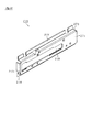
図8に示すように、前記金具200,220の他に、左右に延びる長尺状のプレート240,241が、筐体11の内周縁の上側縁と下側縁とに沿って配されている。これらプレート240,241は、ビス等の締結具(図示略)により天板11a及び底板11bにそれぞれ固定されている。これらプレート240,241は、前記金具200,220とともに、筐体11の補強材としての機能と、筐体11の開口部の遮蔽材としての機能とを有するものである。   As shown in FIG. 8, in addition to the metal fittings 200 and 220, long plates 240 and 241 extending in the left and right directions are arranged along the upper and lower edges of the inner peripheral edge of the housing 11. . These plates 240 and 241 are respectively fixed to the top plate 11a and the bottom plate 11b by fasteners (not shown) such as screws. These plates 240 and 241, together with the metal fittings 200 and 220, have a function as a reinforcing material for the housing 11 and a function as a shielding material for the opening of the housing 11.

各プレート240,241の前端部は筐体11の開口縁部からスロットマシン10の前方に突出しており、前記金具200,220の前端部もまた開口縁部の全域でスロットマシン10の前方に突出している。すなわち、プレート240,241及び金具200,220は、前面扉12が閉止状態で筐体11に取り付けられている場合に、筐体11の開口縁部と前面扉12の外周後端とが対向する部分の隙間を内側より塞ぐように構成されている。このように、各金具200,220及び各プレート240,241を配することで、上述した隙間から針金やフィルム等を侵入させようとしてもそれが阻止でき、不正行為の防止が図られている。   The front ends of the plates 240 and 241 protrude from the opening edge of the housing 11 to the front of the slot machine 10, and the front ends of the metal fittings 200 and 220 also protrude to the front of the slot machine 10 across the entire opening edge. ing. That is, when the front door 12 is attached to the housing 11 with the front door 12 closed, the plates 240 and 241 and the metal fittings 200 and 220 face the opening edge of the housing 11 and the outer peripheral rear end of the front door 12. It is comprised so that the clearance gap between parts may be plugged from the inside. As described above, by arranging the metal fittings 200 and 220 and the plates 240 and 241, it is possible to prevent a wire, a film, or the like from entering the gap described above, and to prevent an illegal act.

また、プレート240の左右両端部には、筐体11の内側を向くように鉛直に折り曲げられて折曲部242,243が形成されている。これら折曲部242,243は、隣接する金具200,220に対し、スロットマシン10の側面視にて上下方向で重なるように、且つ筐体11の開口縁部の前側で重なるように形成されている(図8の部分拡大図に右側の折曲部243と金具220との関係を示す)。このように、プレート240と金具200,220とが筐体11の開口の隅部前側で重なる構成としたことで、同隅部に生じる隙間を少なくすることができる。これにより、それら隅部からの針金やフィルム等の侵入を抑制することが可能となる。なお、プレート240だけでなく、プレート241も同様の構成とすることで、より好適に不正行為を防止することが可能となる。   Further, bent portions 242 and 243 are formed at both left and right end portions of the plate 240 by being bent vertically so as to face the inside of the housing 11. These bent portions 242 and 243 are formed so as to overlap with the adjacent metal fittings 200 and 220 in the vertical direction in a side view of the slot machine 10 and on the front side of the opening edge of the housing 11. (The relationship between the bent portion 243 on the right side and the metal fitting 220 is shown in the partially enlarged view of FIG. 8). As described above, the plate 240 and the metal fittings 200 and 220 are configured to overlap each other in front of the corner of the opening of the housing 11, so that a gap generated in the corner can be reduced. Thereby, it becomes possible to suppress the penetration | invasion of the wire, a film, etc. from those corner parts. Note that not only the plate 240 but also the plate 241 has the same configuration, so that it is possible to more appropriately prevent fraud.

筐体11内の高さ方向のほぼ中央位置(前記ホッパ装置110の上方)には、左側板11dと右側板11eとの間に渡されて仕切り板250が水平に取り付けられており、同仕切り板250によって筐体11の内部が上下に分割されている。仕切り板250より上方の空間は面替えユニット400の設置領域となる。仕切り板250の左右両端部及び後端部には、上方向へ直角に折り曲げられた折曲部(図8には後端に形成された折曲部251のみを示す)がそれぞれ設けられている。仕切り板250は、これら左右の折曲部をビス等の締結具(図示略)により各側板11d,11eに固定することで、筐体11に取り付けられている。本実施の形態においては、仕切り板250を設けたことで筐体11の補強がなされているが、この仕切り板250を備えない構成とすることで軽量化を図ることも当然可能である。   A partition plate 250 is horizontally mounted between the left side plate 11d and the right side plate 11e at a substantially central position in the height direction in the housing 11 (above the hopper device 110). The inside of the housing 11 is vertically divided by the plate 250. The space above the partition plate 250 is an installation area for the surface changing unit 400. The left and right end portions and the rear end portion of the partition plate 250 are respectively provided with bent portions (only the bent portion 251 formed at the rear end is shown in FIG. 8) bent at a right angle upward. . The partition plate 250 is attached to the housing 11 by fixing these left and right bent portions to the side plates 11d and 11e with fasteners (not shown) such as screws. In the present embodiment, the housing 11 is reinforced by providing the partition plate 250, but it is of course possible to reduce the weight by adopting a configuration in which the partition plate 250 is not provided.

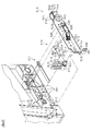
(支持ユニット260と支持レール300との説明)
筐体11の左側板11dにおいて、仕切り板250の上側には、面替えユニット400を搭載するための支持ユニット260が固定されている(図8,9を参照)。支持ユニット260は、仕切り板250の左側の折曲部に固定された金属製のスペーサ部材270と、同スペーサ部材270に取り付けられ、面替えユニット400を支持及び案内する金属製の支持レール300とを備えている。また、筐体11の右側板11eにおいて、仕切り板250の上側には、左側の支持レール300と同じ高さで且つ同じ構成を有する右側の支持レール300が固定されている。
(Description of support unit 260 and support rail 300)
In the left side plate 11d of the housing 11, a support unit 260 for mounting the surface changing unit 400 is fixed above the partition plate 250 (see FIGS. 8 and 9). The support unit 260 includes a metal spacer member 270 fixed to the left bent portion of the partition plate 250, and a metal support rail 300 that is attached to the spacer member 270 and supports and guides the surface changing unit 400. It has. In the right side plate 11 e of the housing 11, the right support rail 300 having the same height and the same configuration as the left support rail 300 is fixed above the partition plate 250.

先ず図10を用いて、スペーサ部材270の構成について説明する。スペーサ部材270は、支持レール300を搭載するための搭載部271を有しており、同搭載部271は略矩形状の板状をなしている。搭載部271の略中央には、同搭載部271の長手方向に向かって延びる長孔272が形成されている。また、搭載部271の短手方向両端部には、同一側へ垂直に折り曲げてフランジ部273が形成されており、これらフランジ部273には仕切り板250への取付部274が設けられている。取付部274が、仕切り板250の左側の折曲部にスポット溶接等の固定手段により固定されることで、スペーサ部材270が仕切り板250に取り付けられるようになっている。本実施の形態においては、スペーサ部材270を一枚の鉄製板材から板金成形しているが、アルミニウム等の軽金属を用いてもよいし、合成樹脂材を用いて形成することも可能である。   First, the configuration of the spacer member 270 will be described with reference to FIG. The spacer member 270 has a mounting portion 271 for mounting the support rail 300, and the mounting portion 271 has a substantially rectangular plate shape. A long hole 272 extending in the longitudinal direction of the mounting portion 271 is formed in the approximate center of the mounting portion 271. Further, flange portions 273 are formed at both ends in the short direction of the mounting portion 271 by being bent perpendicularly to the same side, and these flange portions 273 are provided with attachment portions 274 to the partition plate 250. The spacer member 270 is attached to the partition plate 250 by fixing the attachment portion 274 to the left bent portion of the partition plate 250 by a fixing means such as spot welding. In the present embodiment, the spacer member 270 is formed from a single iron plate material, but a light metal such as aluminum may be used or a synthetic resin material may be used.

次に、支持レール300について説明する。支持レール300はスペーサ部材270と同様に長尺状をなしており、左側の支持レール300はスペーサ部材270に、右側の支持レール300は仕切り板250にそれぞれ取り付けられている。左右の支持レール300は何れも同じ構造を有するため、以下、左側の支持レール300の構成について図11を用いて説明する。   Next, the support rail 300 will be described. The support rail 300 is elongated like the spacer member 270, the left support rail 300 is attached to the spacer member 270, and the right support rail 300 is attached to the partition plate 250. Since the left and right support rails 300 have the same structure, the configuration of the left support rail 300 will be described below with reference to FIG.

支持レール300は、スペーサ部材270の搭載部271に接続するためのベース板部310を有しており、同ベース板部310は略矩形状の板状をなしている。ベース板部310においてその長手方向の一端部には、直角に折り曲げられて誘導片311が設けられている。支持レール300が筐体11側に取り付けられた状態で、ベース板部310に対して誘導片311の折り曲げ先端側がスロットマシン10における外側であり、ベース板部310の長手方向において誘導片311の形成された側がスロットマシン10における前側である。以下、図11において、これらの方向を前提として支持レール300を説明する。誘導片311の設けられた側と対向するベース板部310の端部には、ベース板部310に直角で同ベース板部310の長手方向に延びるストッパ片316が内側に折り曲げられて形成されている。   The support rail 300 has a base plate portion 310 for connecting to the mounting portion 271 of the spacer member 270, and the base plate portion 310 has a substantially rectangular plate shape. A guide piece 311 is provided at one end in the longitudinal direction of the base plate portion 310 by being bent at a right angle. In a state where the support rail 300 is attached to the housing 11 side, the bending tip end side of the guide piece 311 is outside the slot machine 10 with respect to the base plate portion 310, and the guide piece 311 is formed in the longitudinal direction of the base plate portion 310. This side is the front side in the slot machine 10. Hereinafter, in FIG. 11, the support rail 300 will be described on the assumption of these directions. A stopper piece 316 extending in the longitudinal direction of the base plate portion 310 at a right angle to the base plate portion 310 is formed at the end of the base plate portion 310 facing the side on which the guide piece 311 is provided. Yes.

ベース板部310の長辺には、筐体11の内側へ直角に折り曲げて下側ガイド部320が形成されている。ベース板部310の短手方向において下側ガイド部320の形成された側は、支持レール300が筐体11側に取り付けられた状態でスロットマシン10における下側である。   On the long side of the base plate portion 310, a lower guide portion 320 is formed by bending at right angles to the inside of the housing 11. The side where the lower guide part 320 is formed in the short direction of the base plate part 310 is the lower side in the slot machine 10 with the support rail 300 attached to the housing 11 side.

下側ガイド部320は、ベース板部310の長手方向に水平に延びる水平部321と、水平部321の前側で斜め下方に傾斜するように折り曲げて形成された前方傾斜部322と、水平部321の後側で斜め下方に傾斜するように折り曲げて形成された後方傾斜部323とを有する。   The lower guide part 320 includes a horizontal part 321 that extends horizontally in the longitudinal direction of the base plate part 310, a front inclined part 322 that is formed to be inclined obliquely downward on the front side of the horizontal part 321, and a horizontal part 321. And a rear inclined portion 323 formed by being bent obliquely downward on the rear side.

また、水平部321の上面には、水平部321と前方傾斜部322との境界を前端として樹脂ピース330が配されている。樹脂ピース330は、水平部321上に突出して設けられており、前側で斜め下方に傾斜した前方傾斜面331と、後側で斜め下方に傾斜した後方傾斜面332と、両傾斜面331,332の上部を繋ぐ頂部333とを有する。本実施の形態において、頂部333は平面で構成されているが、これに限定されるものではなく、その外形線が曲線状(R形状)をなすように構成されてもよい。樹脂ピース330は、面替えユニット400の落下を防止するための落下防止手段を構成するが、詳細については後述する。なお、樹脂ピース330の代わりに、支持レール300の前部を折り曲げて突状部を形成することで落下防止手段を構成してもよい。これにより、部品点数を削減することが可能となる。   A resin piece 330 is disposed on the upper surface of the horizontal portion 321 with the boundary between the horizontal portion 321 and the front inclined portion 322 as the front end. The resin piece 330 is provided so as to protrude on the horizontal portion 321, and has a front inclined surface 331 inclined obliquely downward on the front side, a rear inclined surface 332 inclined obliquely downward on the rear side, and both inclined surfaces 331, 332. And a top portion 333 connecting the upper portions of the two. In the present embodiment, the top portion 333 is configured as a plane, but the configuration is not limited thereto, and the outer shape line may be configured to have a curved shape (R shape). The resin piece 330 constitutes a fall prevention means for preventing the face change unit 400 from dropping, and details thereof will be described later. Instead of the resin piece 330, the fall prevention means may be configured by bending the front portion of the support rail 300 to form a protruding portion. Thereby, the number of parts can be reduced.

水平部321の下面の前部には、略L字状に形成された折曲部材340が取り付けられている。折曲部材340は、水平部321に取り付けるための平板状の取付部341と、水平部321の下側に突出し、同水平部321の長手方向に直交する座面342とを有する。また、座面342の略中央には、水平部321の長手方向を基準として前側に延びるように先細り形状の突起343が設けられている。本実施の形態においては、折曲部材340を別体で設けているが、下側ガイド部320を折り曲げて形成してもよい。   A bending member 340 formed in a substantially L shape is attached to the front part of the lower surface of the horizontal part 321. The bending member 340 has a flat plate-like attachment portion 341 for attachment to the horizontal portion 321, and a seat surface 342 that protrudes below the horizontal portion 321 and is orthogonal to the longitudinal direction of the horizontal portion 321. In addition, a tapered protrusion 343 is provided at substantially the center of the seating surface 342 so as to extend forward with respect to the longitudinal direction of the horizontal portion 321. In the present embodiment, the bending member 340 is provided separately, but the lower guide portion 320 may be formed by bending.

ベース板部310の上端部で後側には、下側ガイド部320と対向するように上側ガイド部350が直角に折り曲げられて形成されている。上側ガイド部350は、下側ガイド部320と同様に前後方向へ水平に延びるように設けられており、その前部に形成された切り起こし351(切り欠き352)を境にして前後に分割されている。符号350aは分割された前側の上側ガイド部350を示し、符号350bは分割された後側の上側ガイド部350を示す。切り起こし351の上部には、その上端を内側に折り曲げることによってストッパ353が形成されおり、ストッパ353の内側の端部には、上方へ向かって起立した起立部354が形成されている。上側ガイド部350は、面替えユニット400側の後述するスライドレール510に対応しており、同スライドレール510と共に面替えユニット400の浮き上がりを抑える浮き上がり抑制機能を有する。また、切り起こし351(切り欠き352)は、面替えユニット400側の後述するレバー部材610と共に内側筐体410を筐体11に対して係止する係止手段を構成し、ストッパ353、起立部354は、同レバー部材610と共に係止解除操作を補助する補助手段を構成する。なお、上側ガイド部350の詳細な説明については後述する。   On the rear side of the upper end of the base plate portion 310, an upper guide portion 350 is formed by being bent at a right angle so as to face the lower guide portion 320. The upper guide portion 350 is provided so as to extend horizontally in the front-rear direction similarly to the lower guide portion 320, and is divided forward and backward with a cut-and-raised 351 (notch 352) formed in the front portion as a boundary. ing. Reference numeral 350a denotes a divided front upper guide part 350, and reference numeral 350b denotes a divided rear upper guide part 350. A stopper 353 is formed on the upper portion of the cut and raised 351 by bending the upper end thereof inward, and an upright portion 354 that rises upward is formed on the inner end of the stopper 353. The upper guide portion 350 corresponds to a slide rail 510 (to be described later) on the surface changing unit 400 side, and has a lifting restraining function that suppresses the lifting of the surface changing unit 400 together with the slide rail 510. Further, the cut-and-raised 351 (notch 352) constitutes a locking means for locking the inner housing 410 to the housing 11 together with a later-described lever member 610 on the surface changing unit 400 side, and includes a stopper 353 and an upright portion. 354 constitutes auxiliary means for assisting the unlocking operation together with the lever member 610. A detailed description of the upper guide portion 350 will be described later.

ベース板部310は、スペーサ部材270の搭載部271に当接された状態で、ボルト止めやスポット溶接等の固定手段によって固定される。これにより、支持レール300はスペーサ部材270に取り付けられる。支持レール300のベース板部310の略中央には、同支持レール300の長手方向に向かって延びる誘導孔部312が形成されており、スペーサ部材270の長孔272はこれに対応して形成されている。すなわち、スペーサ部材270に支持レール300を位置合わせして取り付けることで誘導孔部312と長孔272とが貫通するようになっている。誘導孔部312の詳細については後述する。   The base plate portion 310 is fixed by fixing means such as bolting or spot welding in a state where the base plate portion 310 is in contact with the mounting portion 271 of the spacer member 270. Thereby, the support rail 300 is attached to the spacer member 270. A guide hole portion 312 extending in the longitudinal direction of the support rail 300 is formed in the approximate center of the base plate portion 310 of the support rail 300, and the long hole 272 of the spacer member 270 is formed correspondingly. ing. In other words, the guide hole portion 312 and the long hole 272 are penetrated by attaching the support rail 300 to the spacer member 270 in alignment. Details of the guide hole 312 will be described later.

(スペーサ部材270と金具200,220との関係)
前記スペーサ部材270は、仕切り板250の左側の折曲部と支持レール300とを離間して接続するスペーサとしての機能を有するものである。ここで、スペーサ部材270と各支持レール300と筐体11の前記金具200,220との相互の関係について図12を用いて説明する。
(Relationship between spacer member 270 and metal fittings 200 and 220)
The spacer member 270 functions as a spacer that connects the bent portion on the left side of the partition plate 250 and the support rail 300 to be separated from each other. Here, the mutual relationship among the spacer member 270, each support rail 300, and the metal fittings 200 and 220 of the housing 11 will be described with reference to FIG.

上述したように、筐体11の左側板11dには、その内側に扉支持金具200が設けられている。左側板11dからの扉支持金具200の突出量W1よりも、左側板11dからの支持レール300(詳しくは下側ガイド部320)のオフセット量W2のほうが大きくなるようにスペーサ部材270によってオフセット量W2が調整されている。これにより、後述する面替えユニット400を筐体11に着脱する際に、面替えユニット400が扉支持金具200に干渉することを回避できる。   As described above, the left side plate 11d of the housing 11 is provided with the door support fitting 200 on the inside thereof. The offset amount W2 is offset by the spacer member 270 such that the offset amount W2 of the support rail 300 (specifically, the lower guide portion 320) from the left side plate 11d is larger than the projection amount W1 of the door support metal fitting 200 from the left side plate 11d. Has been adjusted. Thereby, when the surface changing unit 400 described later is attached to or detached from the housing 11, it is possible to avoid the surface changing unit 400 from interfering with the door support fitting 200.

一方、筐体11の右側板11eには、その内側に鉤受け金具220が設けられている。右側板11eからの鉤受け金具220の突出量W3は、支持レール300の幅(下側ガイド部320の幅)よりも十分に小さい。すなわち、支持レール300を右側板11eに取り付けた状態でも、面替えユニット400を支持するための下側ガイド部320が鉤受け金具220よりも内側に張り出し、同面替えユニット400を支持するための下側ガイド部320の幅を確保可能である。故に、スペーサ部材を用いることなく、面替えユニット400の着脱の際に、同面替えユニット400が鉤受け金具220に干渉することを回避できる。鉤受け金具220の突出量W3は、筐体11の開口部の剛性向上や、鉤受け金具220自身の剛性向上、筐体11と前面扉12との境界部位から行われる不正行為等に対応することで大きくなりがちである。このように突出量W3が大きくなり面替えユニット400の着脱に支障が生じる場合には、右側板11eにおいても左側の支持ユニット260と同様にスペーサ部材を設けることで干渉を回避することができる。   On the other hand, the right side plate 11e of the housing 11 is provided with a hook receiving metal 220 inside thereof. The protrusion amount W3 of the hook receiving metal 220 from the right side plate 11e is sufficiently smaller than the width of the support rail 300 (the width of the lower guide portion 320). That is, even when the support rail 300 is attached to the right side plate 11e, the lower guide portion 320 for supporting the surface changing unit 400 projects inward from the flange receiving metal 220, and supports the surface changing unit 400. The width of the lower guide part 320 can be secured. Therefore, it is possible to avoid the same surface changing unit 400 from interfering with the hook receiving metal 220 when the surface changing unit 400 is attached or detached without using a spacer member. The protrusion amount W3 of the collar bracket 220 corresponds to an improvement in the rigidity of the opening of the casing 11, an improvement in the rigidity of the collar bracket 220 itself, an illegal act performed from the boundary portion between the casing 11 and the front door 12. It tends to be big. Thus, when the protrusion amount W3 becomes large and troubles in attaching and detaching the surface changing unit 400 occur, interference can be avoided by providing a spacer member on the right side plate 11e as well as the left support unit 260.

このように、面替えユニット400の着脱が金具200,220によって妨げられない構成としているために、同面替えユニット400の装着の度に金具200,220を取り外す必要がなく、同面替えユニット400の着脱を効率的に行うことができる。また、支持レール300のオフセットは、面替えユニット400の効率的な着脱のためには不可欠であるが、オフセット量W2を無意味に大きくすると筐体11内部のデッドスペースが増える等の不都合が生じる。そこで、本実施の形態においては、突出量W1とオフセット量W2とを同等とすることで、筐体11の内部スペースを効率的に利用している。   As described above, since the attachment / detachment of the surface changing unit 400 is not hindered by the metal fittings 200, 220, it is not necessary to remove the metal fittings 200, 220 every time the surface changing unit 400 is attached, and the same surface changing unit 400. Can be efficiently attached and detached. Further, the offset of the support rail 300 is indispensable for the efficient attachment / detachment of the surface changing unit 400. However, if the offset amount W2 is increased meaninglessly, a disadvantage such as an increase in the dead space inside the housing 11 occurs. . Therefore, in the present embodiment, the internal space of the housing 11 is efficiently used by making the protrusion amount W1 and the offset amount W2 equal.

再び図8及び図9を用いて説明すれば、支持レール300は、各側板11d,11eに平行で前後方向に延びる長板状のベース板部310の他に、同ベース板部310の下端で内側に垂直に折り曲げて形成された下側ガイド部320と、同ベース板部310の上端で内側に垂直に折り曲げて形成された上側ガイド部350とを備えている。このように、各ガイド部320,350を左右に並設するのではなく上下に並設することで、筐体11内の左右方向のスペースを有効に利用することができる。また、本実施の形態においては、一枚の板材の両端を同一側に折り曲げることで各ガイド部320,350を形成し、部品点数の削減を図っている。   8 and 9 again, the support rail 300 is formed at the lower end of the base plate portion 310 in addition to the long plate-like base plate portion 310 that is parallel to the side plates 11d and 11e and extends in the front-rear direction. The lower guide part 320 is formed by being bent vertically inward, and the upper guide part 350 is formed by being bent vertically inward at the upper end of the base plate part 310. Thus, by arranging the guide portions 320 and 350 side by side rather than side by side, the space in the left and right direction in the housing 11 can be used effectively. In the present embodiment, the guide portions 320 and 350 are formed by bending both ends of a single plate material to the same side, thereby reducing the number of components.

(面替えユニット400の説明)
次に、筐体11の内部に装着される面替えユニット400の構造について説明する。図13は面替えユニット400を斜め上方から見た斜視図、図14は面替えユニット400の背面構成を示す斜視図、図15は面替えユニット400の正面図、図16は面替えユニット400の背面図、図17は面替えユニット400の右側面図、図18は面替えユニット400の内側扉700の開放状態を示す斜視図、図19は面替えユニット400を主要構成部品毎に分解して示す分解斜視図である。なお、以下の面替えユニット400の説明では、特に指定しない限り図15の状態を基準に上下左右等の方向を記述する。
(Description of the surface changing unit 400)
Next, the structure of the surface changing unit 400 mounted inside the housing 11 will be described. 13 is a perspective view of the surface changing unit 400 as viewed obliquely from above, FIG. 14 is a perspective view showing the rear structure of the surface changing unit 400, FIG. 15 is a front view of the surface changing unit 400, and FIG. 17 is a right side view of the surface changing unit 400, FIG. 18 is a perspective view showing an open state of the inner door 700 of the surface changing unit 400, and FIG. 19 is an exploded view of the surface changing unit 400 for each main component. It is a disassembled perspective view shown. In the following description of the surface changing unit 400, directions such as up, down, left and right are described based on the state of FIG. 15 unless otherwise specified.

面替えユニット400は主要な構成として、前面側が開放された箱状の内側筐体410と、同内側筐体410の内部に配設されるリール装置650と、内側筐体410の開口の右縁部(前面扉12の開閉軸線と反対側)を軸線として手前側に開放されるように取り付けられる内側扉700とを備える。本実施の形態においては、面替えユニット400は、本スロットマシン10の遊技内容を決定する主要部品を全て備える構成となっており、仮に遊技ホール等において機種入替を行う場合には、この面替えユニット400を現機種のものから新たな機種のものに入れ替えることで機種入替を行うことができるようになっている。すなわち、面替えユニット400は機種入替時などにおける交換ユニットを構成している。以下、各構成部品を個々に詳しく説明する。   The main surface changing unit 400 mainly includes a box-shaped inner casing 410 whose front side is open, a reel device 650 disposed inside the inner casing 410, and a right edge of the opening of the inner casing 410. And an inner door 700 attached so as to be opened to the front side with the portion (the side opposite to the opening / closing axis of the front door 12) as an axis. In the present embodiment, the face change unit 400 is configured to include all the main parts that determine the game content of the slot machine 10, and if the model change is performed in a game hall or the like, this face change unit 400 The model can be changed by replacing the unit 400 with the new model. That is, the surface changing unit 400 constitutes an exchange unit at the time of model change. Each component will be described in detail below.

(内側筐体410の説明)
内側筐体410の構成について図13〜図19及び図20に基づいて説明する。図20は内側筐体410の構成を示す斜視図である。内側筐体410は、例えばABS等の合成樹脂により一体成形されている。この場合、内側筐体410を樹脂製一体成形品とすることで、製造が容易となる。内側筐体410の前側縁部の右側(前面扉12の扉支持金具200と反対側)には金属製の扉支持金具740が配されており、前側縁部の左側には鉤受け金具750が配されている。さらに、前側縁部の上下両側には、長尺状に形成された補強プレート411,415が配されており、同補強プレート411,415の左右の端部は金具740,750に連結されている。このように補強プレート411,415と金具740,750とを互いに連結することで枠状とし、内側筐体410の開口縁周りに配することで内側扉700の支持剛性の向上を図っている。
(Description of inner casing 410)
A configuration of the inner housing 410 will be described with reference to FIGS. 13 to 19 and 20. FIG. 20 is a perspective view showing the configuration of the inner housing 410. The inner housing 410 is integrally formed of a synthetic resin such as ABS. In this case, manufacturing is facilitated by making the inner housing 410 an integrally molded product made of resin. A metal door support fitting 740 is arranged on the right side of the front side edge of the inner housing 410 (on the side opposite to the door support fitting 200 of the front door 12), and a barb fitting 750 is provided on the left side of the front side edge. It is arranged. Further, elongated reinforcing plates 411 and 415 are disposed on both the upper and lower sides of the front edge, and the left and right ends of the reinforcing plates 411 and 415 are connected to the metal fittings 740 and 750. . In this way, the reinforcing plates 411 and 415 and the metal fittings 740 and 750 are connected to each other to form a frame shape and arranged around the opening edge of the inner housing 410 to improve the support rigidity of the inner door 700.

内側筐体410は、天板部410a、底板部410b、背板部410c、左側板部410d及び右側板部410eからなり、全体として前面側が開放された箱状に形成されている。なお、内側筐体410は合成樹脂によって構成する以外に、木製パネル又は金属製パネルによって構成してもよいし、木材又は金属材料を用いて一体の箱状に形成することで構成してもよい。   The inner housing 410 includes a top plate portion 410a, a bottom plate portion 410b, a back plate portion 410c, a left side plate portion 410d, and a right side plate portion 410e, and is formed in a box shape with the front side opened as a whole. In addition to the synthetic resin, the inner housing 410 may be constituted by a wooden panel or a metal panel, or may be constituted by forming a single box using wood or a metal material. .

図20に示すように、天板部410aの前部は、壁板が内外に二重に形成されており、これら壁板の間には、両者を繋ぐように多数の補強リブ420が設けられている。その補強リブ420を設けた部分が格子状の補強バー部421となっており、補強バー部421の中央には持ち手部としての貫通長孔422が形成されている。図13〜図19を用いて説明すれば、補強バー部421には、補強プレート411がビス等の締結具によって固定されており、その補強プレート411の略中央には、貫通長孔422に対応して切り欠き412が形成されている。貫通長孔422に指を通すことで、内側筐体410(面替えユニット400)を容易に持ち上げることができるようになっている。また、補強バー部421の後方には複数箇所(図では4カ所)に内外に貫通する開口部423が形成されており、これら開口部423を介して面替えユニット400の内部から熱を帯びた空気を排出することができる。   As shown in FIG. 20, the front part of the top plate part 410a has double wall plates formed inside and outside, and a plurality of reinforcing ribs 420 are provided between the wall plates so as to connect the two. . The portion provided with the reinforcing rib 420 is a lattice-shaped reinforcing bar portion 421, and a through long hole 422 as a handle portion is formed at the center of the reinforcing bar portion 421. 13 to 19, the reinforcing plate 411 is fixed to the reinforcing bar portion 421 by a fastener such as a screw, and the reinforcing plate 411 has a central portion corresponding to the through long hole 422. Thus, a notch 412 is formed. The inner casing 410 (the surface changing unit 400) can be easily lifted by passing a finger through the through-hole 422. In addition, openings 423 penetrating inward and outward are formed at a plurality of locations (four locations in the figure) behind the reinforcing bar portion 421, and heat is applied from the inside of the surface changing unit 400 through these openings 423. Air can be discharged.

天板部410aには、面替えユニット400の着脱方向に延びる主リブ425と、同主リブ425に交差して延びる副リブ426とがそれぞれ複数形成されている。主リブ425の後部には斜め下方に傾斜した傾斜面427が形成されている。これらリブ425,426は天板部410aの剛性を高める補強部としての機能を有する。リブ425,426のその他の機能については後述する。   A plurality of main ribs 425 extending in the attaching / detaching direction of the surface changing unit 400 and a plurality of sub ribs 426 extending intersecting the main ribs 425 are formed on the top plate portion 410a. An inclined surface 427 inclined obliquely downward is formed at the rear portion of the main rib 425. These ribs 425 and 426 have a function as a reinforcing portion that increases the rigidity of the top plate portion 410a. Other functions of the ribs 425 and 426 will be described later.

底板部410bの外面は全体として略平面状に形成されており、面替えユニット400を単体で運搬する際に地面等に置くための載置部を構成する。また、面替えユニット400を筐体11の内部に装着完了した状態においては、前記仕切り板250の前端縁に対し底板部410bの前側の一部が前方に突出する構成となっており、この突出部430に横長状の貫通長孔431が設けられている。また、この貫通長孔431に対応して、補強プレート415にも図示せぬ貫通長孔が設けられている。このように貫通長孔431を設けることで、面替えユニット400の着脱を行う際に、同貫通長孔431に指を通して押し引きすることで作業を容易に行うことが可能となる。   The outer surface of the bottom plate portion 410b is formed in a substantially flat shape as a whole, and constitutes a placement portion for placing the surface change unit 400 on the ground or the like when transporting alone. In addition, in the state where the surface changing unit 400 is completely mounted in the housing 11, a part of the front side of the bottom plate portion 410 b protrudes forward with respect to the front end edge of the partition plate 250. The part 430 is provided with a horizontally long through-hole 431. Corresponding to the through long hole 431, the reinforcing plate 415 is also provided with a through long hole (not shown). By providing the through long hole 431 as described above, when attaching and detaching the surface changing unit 400, it is possible to easily perform the work by pushing and pulling the through long hole 431 with a finger.

図20に示すように、底板部410bの内面には各側板部410d,410eに沿って前後に延びる突条部435が左右に設けられている。各突条部435の前面の略中央には、手前側に延びるようにして円柱状の突起436がそれぞれ設けられている。また、それら突起436の中央にはビス止め用のねじ穴437が設けられている。図20には、左側の突条部435と左側の突起436と左側のねじ穴437とを示す。   As shown in FIG. 20, on the inner surface of the bottom plate portion 410b, protrusions 435 extending in the front-rear direction along the side plate portions 410d and 410e are provided on the left and right. A columnar protrusion 436 is provided at the approximate center of the front surface of each protrusion 435 so as to extend to the front side. Further, a screw hole 437 for screwing is provided at the center of the protrusion 436. FIG. 20 shows a left protrusion 435, a left protrusion 436, and a left screw hole 437.

背板部410cは、図17(面替えユニット400の側面図)に見られるように、概ね平面状をなしている。面替えユニット400が筐体11内に装着完了された状態において、同筐体11の背板11cと略平行になるように背板部410cは形成されている。このため筐体11の奥行き領域にデットスペースが生じることを抑え、同奥行き領域を有効に活用することができる。更に、同デッドスペースへの不正基板等の設置を抑制することも可能となる。   As can be seen in FIG. 17 (side view of the surface changing unit 400), the back plate portion 410c has a generally planar shape. The back plate portion 410 c is formed so as to be substantially parallel to the back plate 11 c of the housing 11 in a state where the surface changing unit 400 is completely mounted in the housing 11. For this reason, it is possible to suppress the occurrence of a dead space in the depth region of the housing 11 and to effectively use the depth region. Further, it is possible to suppress the installation of an illegal substrate or the like in the dead space.

背板部410cの下部には段差状に凹んだ段部440が形成されている。段部440の左右両側には後方に向かって突出した突部441が設けられている。面替えユニット400が筐体11に装着完了された際には、これら突部441が、前記仕切り板250の折曲部251に当接することで(背板部410cと背板11cとは干渉しない)、面替えユニット400の奥行き方向の位置決めがなされる。すなわち、各突部441と折曲部251とは、面替えユニット400の奥行き方向位置決め手段を構成している。本実施の形態においては、突部441が折曲部251と当接される構成としたが、突部441が背板11cに当接される構成としてもよい。   A step portion 440 that is recessed in a step shape is formed in the lower portion of the back plate portion 410c. Protrusions 441 that protrude rearward are provided on the left and right sides of the step portion 440. When the surface changing unit 400 is completely attached to the housing 11, the protrusions 441 come into contact with the bent portion 251 of the partition plate 250 (the back plate portion 410c and the back plate 11c do not interfere with each other). ), Positioning of the surface changing unit 400 in the depth direction is performed. That is, each protrusion 441 and the bent portion 251 constitute a depth direction positioning unit of the surface changing unit 400. In the present embodiment, the protrusion 441 is in contact with the bent portion 251. However, the protrusion 441 may be in contact with the back plate 11c.

なお、内側筐体410の背板部410cの外面、又は筐体11の背板11cの内面にウレタンスポンジやシリコンパッド等の反発力の小さい緩衝材を配することにより、面替えユニット400を装着する際の突部441と折曲部251との衝突を緩和することが可能である。   The surface changing unit 400 is mounted by placing a cushioning material having a small repulsive force such as urethane sponge or silicon pad on the outer surface of the back plate portion 410c of the inner housing 410 or the inner surface of the back plate 11c of the housing 11. It is possible to alleviate the collision between the protruding portion 441 and the bent portion 251 at the time.

図14,図16(面替えユニット400の背面斜視図、面替えユニット400の背面図)に見られるように、背板部410cの略中央には横長状の収容凹部442が形成されており、同収容凹部442の底部には、内外に貫通した横長の孔部443が形成されている。これら収容凹部442と孔部443との詳細ついては後述する。   As shown in FIGS. 14 and 16 (a rear perspective view of the surface changing unit 400, a rear view of the surface changing unit 400), a horizontally-long accommodating recess 442 is formed in the approximate center of the back plate portion 410c. A horizontally long hole 443 is formed in the bottom of the housing recess 442 so as to penetrate inside and outside. Details of the housing recess 442 and the hole 443 will be described later.

左側板部410dについて図18,図20(面替えユニット400の正面図斜視図、内側筐体410の正面斜視図)を用いて説明する。左側板部410dの上部には矩形状の開口部450が内外に貫通するように形成されている。開口部450の下側には、同じく矩形状の開口部451が内外に貫通するように形成されている。以下の記載では上側の開口部を「上側開口部450」、下側の開口部を「下側開口部451」と表記する。左側板部410dの下部(下側開口部451の下側)には、背板部410cと底板部410bとに繋がり、内側に凹んだ収容凹部452が形成されている。   The left side plate portion 410d will be described with reference to FIGS. 18 and 20 (a front perspective view of the surface changing unit 400, a front perspective view of the inner housing 410). A rectangular opening 450 is formed in the upper portion of the left side plate portion 410d so as to penetrate inside and outside. A rectangular opening 451 is also formed below the opening 450 so as to penetrate inside and outside. In the following description, the upper opening is referred to as “upper opening 450”, and the lower opening is referred to as “lower opening 451”. An accommodation recess 452 that is connected to the back plate 410c and the bottom plate 410b and is recessed inward is formed in the lower part of the left side plate 410d (below the lower opening 451).

次に、右側板部410eについて図17,図20を用いて説明する。右側板部410eの外側には、同右側板部410eの前端縁に沿って延びる取付基部460が形成されている。取付基部460は、扉支持金具740の取付部を構成している。なお、取付基部460に関しては、図13〜19では確認しにくいため、図20の斜視図を参照されたい。右側板部410eの上部には背板部410cに繋がる凹部462が形成されている。詳述すれば、凹部462は、面替えユニット400を筐体11に装着する際に、筐体11の右側板11eの内側上部に設けられた図示せぬ外部端子との干渉を回避可能な形状で形成されている。凹部462の底部には、内側筐体410の内外に貫通した側面開口部463が設けられており、同側面開口部463を介して外部端子と内側筐体410の内部に設けられた後述する中継基板790とが接続可能となっている。   Next, the right side plate portion 410e will be described with reference to FIGS. A mounting base portion 460 extending along the front edge of the right side plate portion 410e is formed outside the right side plate portion 410e. The attachment base 460 constitutes an attachment part of the door support fitting 740. In addition, since it is difficult to confirm the attachment base 460 in FIGS. 13 to 19, refer to the perspective view of FIG. A concave portion 462 connected to the back plate portion 410c is formed in the upper portion of the right side plate portion 410e. More specifically, the recess 462 has a shape that can avoid interference with an external terminal (not shown) provided on the inner upper portion of the right side plate 11e of the housing 11 when the surface changing unit 400 is mounted on the housing 11. It is formed with. A side opening 463 that penetrates into and out of the inner casing 410 is provided at the bottom of the recess 462, and a later-described relay provided inside the inner casing 410 with the external terminal via the side opening 463. The substrate 790 can be connected.

各側板部410d,410e内面の上下方向の略中央には、同側板部410d,410eに沿って前後に延びる図示せぬ突条部が左右に設けられている。それら突条部の前面には手前側に延びるようにして円柱状の突起475がそれぞれ設けられている(図20には左側の突起475のみ示す)。またそれら突起475の中央にはビス止め用のねじ穴476が設けられている。これら突起475及びねじ穴476は、前記突起436及びねじ穴437と共にリール装置650を保持するための保持手段を構成する。   At substantially the center of the inner surfaces of the side plate portions 410d and 410e in the vertical direction, unillustrated protrusions extending in the front and rear directions along the same side plate portions 410d and 410e are provided on the left and right sides. Columnar protrusions 475 are respectively provided on the front surfaces of the protrusions so as to extend toward the front side (only the left protrusion 475 is shown in FIG. 20). Further, a screw hole 476 for screwing is provided in the center of the protrusion 475. The protrusions 475 and the screw holes 476 constitute holding means for holding the reel device 650 together with the protrusions 436 and the screw holes 437.

また、各側板部410d,410eには、面替えユニット400の着脱方向に延びるガイドリブ470が外側に露出するように複数形成されている。これらガイドリブ470は、その後部に、内側に向かって斜めに傾斜する傾斜面471を有している。各側板部410d,410eには、ガイドリブ470より低く且つ同ガイドリブ470に交差して延びる補助リブ472が複数形成されており、ガイドリブ470及び補助リブ472は側板部410d,410eの剛性を高める補強部としての機能を有する。   Further, a plurality of guide ribs 470 extending in the attaching / detaching direction of the surface changing unit 400 are formed on the side plate portions 410d and 410e so as to be exposed to the outside. These guide ribs 470 have inclined surfaces 471 that are inclined obliquely inward at the rear part thereof. A plurality of auxiliary ribs 472 that are lower than the guide ribs 470 and extend across the guide ribs 470 are formed on the side plate parts 410d and 410e. As a function.

筐体11内部の各側板11d,11e上には、面替えユニット400を筐体11に装着した状態において各ガイドリブ470に対応する位置に、同ガイドリブ470に近接するような大きさで金属製の中空ブロック480,490がそれぞれ設けられている(図8,9参照)。詳述すれば、各側板11d,11eの略中央前側には第1中空ブロック480が設けられており、同側板11d,11eの後側上部には第2中空ブロック490が設けられている。図24に示すように、それら中空ブロック480,490は、上面板部481,491と、下面板部482,492と、前面板部483,493と、後面板部484,494と、側面板部485,495とからなり、同側面板部485,495と対向する側が開放された箱状に板金成形されている。各中空ブロック480,490は、それら中空ブロック480,490の開放された側が筐体11の各側板11d,11e側となるようにして、前面板部483,493と後面板部484,494とを、各側板11d,11eに当接するように配置した状態でビス等の固定具によって固定されている。   On the side plates 11 d and 11 e inside the housing 11, a metal made so as to be close to the guide rib 470 at a position corresponding to each guide rib 470 when the surface changing unit 400 is mounted on the housing 11. Hollow blocks 480 and 490 are respectively provided (see FIGS. 8 and 9). More specifically, a first hollow block 480 is provided at a substantially central front side of each of the side plates 11d and 11e, and a second hollow block 490 is provided at an upper rear side of the side plates 11d and 11e. As shown in FIG. 24, these hollow blocks 480 and 490 are composed of upper plate portions 481 and 491, lower plate portions 482 and 492, front plate portions 483 and 493, rear plate portions 484 and 494, and side plate portions. 485, 495, and is formed into a box shape in which the side facing the side plate portions 485, 495 is opened. Each of the hollow blocks 480 and 490 has the front plate portions 483 and 493 and the rear plate portions 484 and 494 so that the opened side of the hollow blocks 480 and 490 becomes the side plates 11d and 11e side of the housing 11. These are fixed by a fixing tool such as a screw in a state where they are arranged so as to abut on the side plates 11d and 11e.

なお、中空ブロック480,490は側板11d,11eに取り付けるための取付部としてフランジ486,496を有しているが、これらフランジ486,496は張出部として機能する部位ではなく、中空ブロック480,490の大きさにはそれらフランジ部486,496を含めないものとする。因みに、中空ブロック480,490を左右で計4つ設ける構成としたが、個数はこれにとらわれるものではない。また材質も金属ではなくポリカーボネート樹脂等の透明な合成樹脂を用いてもよい。   The hollow blocks 480 and 490 have flanges 486 and 496 as attachment portions for attachment to the side plates 11d and 11e. However, these flanges 486 and 496 are not portions that function as overhanging portions, but the hollow blocks 480 and 490, These flange portions 486 and 496 are not included in the size of 490. Incidentally, although a total of four hollow blocks 480 and 490 are provided on the left and right, the number is not limited to this. Also, the material may be a transparent synthetic resin such as polycarbonate resin instead of metal.

図20に示すように、内側筐体410内の上部には、遊技に関わる主たる各種制御を実施する主制御装置770と、同主制御装置770をリール装置650等の各装置に電気的に接続するための中継基板790とが配されている。これら主制御装置770及び中継基板790についての詳細は後述する。   As shown in FIG. 20, an upper part in the inner housing 410 is electrically connected to a main control device 770 that performs various main controls related to games, and the main control device 770 to each device such as a reel device 650. A relay board 790 is provided. Details of the main controller 770 and the relay board 790 will be described later.

リール装置や主制御基板等を有する交換ユニットを備え、この交換ユニットを交換することで機種入替を行う従来のスロットマシンにおいては、リール装置や主制御基板等を支持するための交換ユニットの支持構造として、柱と梁とを組み合わせた軸組み構造が多く採用されている。本実施の形態においては、上記の如く、リール装置や主制御基板等を支持する支持構造として、各板部410a〜410eの相互の結合によって一体となる面構造を採用している。このように面構造を採用することで、主制御装置770及び中継基板790は内側筐体410の外部から遮蔽されやすくなっている。すなわち、従来の軸組み構造に比べ、主制御装置770及び中継基板790への外部からの不正なアクセスが好適に抑制することができる。さらに、上記の如く内側筐体410が面構造を有することで、面替えユニット400としての強度を向上することもできる。   In a conventional slot machine having an exchange unit having a reel device, a main control board, etc., and changing the model by exchanging the exchange unit, a support structure for the exchange unit for supporting the reel device, the main control board, etc. In many cases, a frame structure in which columns and beams are combined is adopted. In the present embodiment, as described above, as the support structure for supporting the reel device, the main control board, and the like, a surface structure is adopted in which the plate portions 410a to 410e are integrated by mutual coupling. By adopting the surface structure in this way, the main controller 770 and the relay board 790 are easily shielded from the outside of the inner housing 410. That is, unauthorized access from the outside to the main controller 770 and the relay board 790 can be suitably suppressed as compared with the conventional shaft assembly structure. Furthermore, as the inner casing 410 has a surface structure as described above, the strength of the surface changing unit 400 can be improved.

内側筐体410の両側板部410d,410eの外側には、内側筐体410(面替えユニット400)の着脱作業を補助する着脱補助機構と、内側筐体410の着脱の際に、同内側筐体410の着脱方向を規制する規制手段と、内側筐体410の装着完了の際に同内側筐体410を係止する係止手段とが左右同じ高さで設けられている。このように、面替えユニット400を筐体11に装着するための構成が内側筐体410に設けられているため、内側筐体410が筐体11に装着されることで、面替えユニット400の筐体11への装着がなされることとなる。また着脱補助機構及び規制手段が左右同じ高さで設けられていることで、面替えユニットを着脱する際の安定性の向上が期待できる。以下各構成部品を個々に詳しく説明する。   On the outside of both side plate portions 410d and 410e of the inner housing 410, an attachment / detachment assist mechanism for assisting the attaching / detaching operation of the inner housing 410 (the surface changing unit 400), and the inner housing 410 when the inner housing 410 is attached / detached. A restricting means for restricting the attachment / detachment direction of the body 410 and a locking means for locking the inner casing 410 when the inner casing 410 is completely mounted are provided at the same height on the left and right. As described above, since the configuration for mounting the surface changing unit 400 to the housing 11 is provided in the inner housing 410, the mounting of the inner housing 410 to the housing 11 allows the Mounting to the housing 11 is performed. Further, since the attachment / detachment assisting mechanism and the regulating means are provided at the same height on the left and right, an improvement in stability when the surface changing unit is attached / detached can be expected. Each component will be described in detail below.

(スライドレール510の説明)
図13,図18に示すように、左側板部410dの収容凹部452及び右側板部410eの下部には、前後方向に延びる長尺状のスライドレール510が設けられている。スライドレール510は左右何れも同じ構造を有するため、以下右側のスライドレール510について図21,図22(内側筐体410の右側板部410e下部を示す部分拡大図、着脱補助機構と規制手段と係止手段との構成の一部を分解して示す分解斜視図)を用いて説明する。
(Description of slide rail 510)
As shown in FIGS. 13 and 18, a long slide rail 510 extending in the front-rear direction is provided in the housing recess 452 of the left plate portion 410 d and the lower portion of the right plate portion 410 e. Since the slide rail 510 has the same structure on both the left and right sides, the right side slide rail 510 will be described below with reference to FIGS. 21 and 22 (partial enlarged view showing the lower portion of the right side plate 410e of the inner housing 410, the attachment / detachment assist mechanism and the regulating means. A disassembled perspective view showing a part of the structure with the stopping means will be described.

スライドレール510は、右側装着部464への取付部たる長板状の取付板部511を有する。面替えユニット400において、取付板部511に対向する部位に装着部464が設けられており、同装着部464に取付板部511がビス等の締結具によって固定されている。   The slide rail 510 has a long plate-shaped mounting plate portion 511 that is a mounting portion to the right mounting portion 464. In the surface changing unit 400, a mounting portion 464 is provided at a portion facing the mounting plate portion 511, and the mounting plate portion 511 is fixed to the mounting portion 464 by a fastener such as a screw.

取付板部511の下端部には、内側筐体410を装着の際に前記支持レール300によって支持される被支持部512が、外側に折り曲げられて形成されている。被支持部512は前後方向に水平に延びる長板状をなし、その下面は、内側筐体410の装着の際に支持レール300に対して接触した状態となる摺動面512aを構成している。被支持部512の前側には案内部513が斜め上方に折り曲げて形成されており、案内部513によって被支持部512と前記樹脂ピース330との内側筐体410を離脱する際の引っ掛かりが防止されている。また、取付板部511の後端部には外側に直角に折り曲げられて第1押え部514が形成されている。取付板部511の上端部の後側には、前後方向に水平に延びる板状の保持部515が外側に折り曲げられて形成されており、同保持部515の後端部には、第1押え部514との間に所定の隙間を形成するように第2押え部516が下方に折り曲げて形成されている。第1押え部514の上端部と第2押え部516の下端部とによれば、両者の間に挿入部517が構成されている。面替えユニット400が筐体11に装着完了された状態では、挿入部517に支持レール300のストッパ片316が挿入される。挿入部517は、ストッパ片316に対し僅かに大きくなるように形成されている。   A supported portion 512 that is supported by the support rail 300 when the inner housing 410 is mounted is formed at the lower end portion of the mounting plate portion 511 by bending outward. The supported portion 512 has a long plate shape extending horizontally in the front-rear direction, and the lower surface thereof constitutes a sliding surface 512 a that comes into contact with the support rail 300 when the inner housing 410 is attached. . A guide portion 513 is formed on the front side of the supported portion 512 by being bent obliquely upward. The guide portion 513 prevents the supported portion 512 and the resin piece 330 from being caught when the inner casing 410 is detached. ing. Further, a first presser portion 514 is formed at the rear end portion of the mounting plate portion 511 by being bent outward at a right angle. A plate-like holding portion 515 extending horizontally in the front-rear direction is formed on the rear side of the upper end portion of the mounting plate portion 511. The first holding portion is provided at the rear end portion of the holding portion 515. A second pressing portion 516 is formed by bending downward so as to form a predetermined gap with the portion 514. According to the upper end part of the 1st presser part 514 and the lower end part of the 2nd presser part 516, the insertion part 517 is comprised between both. In a state where the surface changing unit 400 is completely mounted on the housing 11, the stopper piece 316 of the support rail 300 is inserted into the insertion portion 517. The insertion portion 517 is formed to be slightly larger than the stopper piece 316.

保持部515の上面には樹脂ピース520が配されている。樹脂ピース520は、保持部515上に突出して設けられており、上部に設けられた平面からなる当接部521と、同当接部521の後側に設けられた斜め下方に傾斜する後方傾斜面522とを備える。本実施の形態においては当接部521が平面で構成されているが、外形線が曲線状をなすように構成されてもよい。また、保持部515を突状に折り曲げて形成することで、樹脂ピースの代わりとしてもよい。   A resin piece 520 is disposed on the upper surface of the holding portion 515. The resin piece 520 is provided so as to protrude on the holding portion 515, and has a contact portion 521 that is a flat surface provided on the upper portion and a rearward inclination that is inclined obliquely downward provided on the rear side of the contact portion 521. A surface 522. In the present embodiment, the contact portion 521 is configured as a flat surface, but may be configured such that the outline is curved. Moreover, it is good also as a substitute of the resin piece by bending the holding | maintenance part 515 in the shape of a protrusion.

取付板部511の外面のほぼ中央には、ガイドピース530が設けられている。ガイドピース530は、外側に向かって張り出したベース部531を有し、同ベース部531をビス等の締結具によって取付板部511に固定されている。ベース部531の後部外側には、後方に向かって延びるアーム532が形成されている。これらベース部531及びアーム532は、内側筐体410が筐体11に装着された状態において、支持レール300のベース板部310と干渉しない大きさで張り出している。アーム532の後端には、外側に向かって突出した突起533が形成されている。詳述すれば、内側筐体410が筐体11に装着された状態において、支持レール300の誘導孔部312に嵌合するように突起533は形成されている。   A guide piece 530 is provided substantially at the center of the outer surface of the mounting plate portion 511. The guide piece 530 has a base portion 531 protruding outward, and the base portion 531 is fixed to the mounting plate portion 511 with a fastener such as a screw. An arm 532 extending rearward is formed on the rear outer side of the base portion 531. The base portion 531 and the arm 532 protrude so as not to interfere with the base plate portion 310 of the support rail 300 in a state where the inner housing 410 is mounted on the housing 11. A projection 533 protruding outward is formed at the rear end of the arm 532. More specifically, the protrusion 533 is formed so as to fit into the guide hole 312 of the support rail 300 in a state where the inner housing 410 is mounted on the housing 11.

また、ガイドピース530は合成樹脂により一体成型されており、アーム532は筐体11の外側方向から外力を受けることで内側に撓む構成となっている。本実施の形態においては、突起533の裏側には、内側筐体410の右側板部410eより突出した支持ピン534が同突起533の裏側に近接して形成されている。これら支持ピン534によって、アーム532は、所定量以上に内側に撓んで塑性変形しないようにその撓み量を規制されている。   Further, the guide piece 530 is integrally formed of synthetic resin, and the arm 532 is configured to bend inward by receiving an external force from the outer side of the housing 11. In the present embodiment, on the back side of the protrusion 533, a support pin 534 protruding from the right side plate portion 410 e of the inner housing 410 is formed close to the back side of the protrusion 533. By these support pins 534, the amount of bending of the arm 532 is restricted so as not to be bent inward by a predetermined amount or more and to be plastically deformed.

これら樹脂ピース520及びガイドピース530は、前述した天板部410aの主リブ425と各側板部410d,410eのガイドリブ470と共に前述した規制手段を構成している。特に、ガイドピース530に関しては、上述した規制手段としての機能に加え、面替えユニット400を筐体11から離脱する際の、手前側への面替えユニット400の抜け落ちを防止する抜け落ち防止機能を併せ有する。   The resin piece 520 and the guide piece 530 together with the main rib 425 of the top plate portion 410a and the guide ribs 470 of the side plate portions 410d and 410e constitute the restricting means described above. In particular, with respect to the guide piece 530, in addition to the function as the restricting means described above, a drop-off preventing function for preventing the face-changing unit 400 from dropping out to the near side when the face-changing unit 400 is detached from the housing 11 is also provided. Have.

被支持部512の後端部の後側、すなわち右側板部410eの後部下側には樹脂製のローラ540が回動可能に設けられている。詳述すれば、ローラ540は、回転軸を筐体11の右側板11eと直交する方向とし、回動可能な状態で取付板部511に対して軸支されており、ローラ540の外周はスライドレール摺動面512aよりも下方に僅かに突出している。   A resin roller 540 is rotatably provided on the rear side of the rear end portion of the supported portion 512, that is, on the lower side of the rear portion of the right side plate portion 410e. More specifically, the roller 540 has a rotating shaft in a direction orthogonal to the right side plate 11e of the housing 11 and is pivotally supported with respect to the mounting plate portion 511 in a rotatable state. It protrudes slightly below the rail sliding surface 512a.

スライドレール510及びローラ540は、筐体11側の支持レール300に対応して設けられている。すなわち、面替えユニット400を筐体11に装着する際には、スライドレール510のスライドレール摺動面512a及びローラ540は、支持レール300の下側ガイド部320に支持されるようになっている。これらスライドレール510及びローラ540によって着脱補助機構が構成されている。   The slide rail 510 and the roller 540 are provided corresponding to the support rail 300 on the housing 11 side. That is, when the surface changing unit 400 is mounted on the housing 11, the slide rail sliding surface 512 a of the slide rail 510 and the roller 540 are supported by the lower guide portion 320 of the support rail 300. . The slide rail 510 and the roller 540 constitute an attachment / detachment assist mechanism.

スライドレール510には、被支持部512の下側に突出した折曲部材550が別体で設けられている。折曲部材550には、支持レール300の突起343に係合可能な係合孔551が形成されており、突起343に係合孔551が係合することで内側筐体410(面替えユニット400)の位置決めがなされる。   The slide rail 510 is separately provided with a bending member 550 that protrudes below the supported portion 512. The bending member 550 is formed with an engagement hole 551 that can be engaged with the protrusion 343 of the support rail 300, and the engagement of the engagement hole 551 with the protrusion 343 causes the inner housing 410 (the surface changing unit 400 to be replaced). ) Is positioned.

上記係合孔については、2箇所(本実施の形態においては左右両側)に異なる形状で設けられているため、これらの違いについて説明する(図15参照)。各係合孔のうち一方の係合孔(本実施の形態においては右側の係合孔551)は、上下方向に延びる長孔状をなしており、右側の突起343と共に内側筐体410(面替えユニット400)の左右方向の位置決めを行う左右方向位置決め手段を構成する。これに対して、他方の係合孔(本実施の形態においては左側の折曲部材552に設けられた係合孔553)は、左右方向に延びる長孔状をなしており、左側の突起343と共に内側筐体410の上下方向の位置決めを行う上下方向位置決め手段を構成する。すなわち、前述した内側筐体410の前後方向の位置決め手段とこれら左右及び上下の位置決め手段とがそれぞれ独立して構成されている。   Since the engagement holes are provided in two different shapes (left and right sides in the present embodiment) in different shapes, these differences will be described (see FIG. 15). One engagement hole (the right engagement hole 551 in the present embodiment) of each engagement hole has a long hole shape extending in the vertical direction, and the inner casing 410 (surface) together with the right protrusion 343. It constitutes a left-right direction positioning means for positioning the replacement unit 400) in the left-right direction. On the other hand, the other engagement hole (in this embodiment, the engagement hole 553 provided in the left bending member 552) has a long hole shape extending in the left-right direction, and the left protrusion 343. At the same time, it constitutes vertical positioning means for positioning the inner casing 410 in the vertical direction. That is, the positioning means in the front-rear direction of the inner casing 410 and the left and right and upper and lower positioning means are configured independently of each other.

面替えユニット400は、リール装置650、内側扉700、主制御装置770等の各部材を備えるため重くなりがちであり、装着の際の衝突による衝撃が各位置決め手段に加わり、それら位置決め手段の変形等の不具合を生じる可能性がある。そこで、本実施の形態においては、もっとも衝撃を受けやすいと考えられる装着方向(本実施の形態においては前後方向)の位置決め手段を、突部441と背板11c(折曲部251)とで構成し、装着の際の衝撃を内側筐体410と筐体11とで受け止める構成とした。上述の通り、前後方向の位置決め手段は左右及び上下の位置決め手段から独立しているため、左右及び上下の位置決め手段に係る負荷を軽減できる。これにより、位置決めの精度を好適に維持することが可能となる。   The surface changing unit 400 tends to be heavy because it includes the reel device 650, the inner door 700, the main control device 770, and the like, and an impact caused by a collision at the time of mounting is applied to each positioning means, and deformation of the positioning means is caused. May cause problems. Therefore, in the present embodiment, the positioning means in the mounting direction (in the present embodiment, the front-rear direction) that is considered to be most susceptible to impact is constituted by the protrusion 441 and the back plate 11c (bent portion 251). Thus, the inner casing 410 and the casing 11 receive an impact at the time of mounting. As described above, since the front-rear direction positioning means is independent of the left-right and upper-lower positioning means, the load on the left-right and upper-lower positioning means can be reduced. Thereby, it becomes possible to maintain the positioning accuracy suitably.

次に、内側筐体410の装着完了の際に同内側筐体410を係止する係止手段の構成を図13,図18を用いて説明する。係止手段としては、各側板部410d,410eに回動自在に設けられた側面視で略L字状をなすレバー部材610と、レバー部材610をその回転方向に付勢するための付勢部材とを備えて構成されている。これら各レバー部材610と各付勢部材とは左右何れも同じ構造を有するので、以下、図21,図22を用いて右側のレバー部材610と右側の付勢部材とについて説明する。   Next, the structure of the locking means for locking the inner casing 410 when the inner casing 410 is completely mounted will be described with reference to FIGS. 13 and 18. As the locking means, a lever member 610 having a substantially L shape in a side view provided rotatably on each of the side plate portions 410d and 410e, and an urging member for urging the lever member 610 in its rotational direction. And is configured. Since each lever member 610 and each biasing member have the same structure on the left and right, the right lever member 610 and the right biasing member will be described below with reference to FIGS. 21 and 22.

右側板部410eの前部で右側装着部464の上側にはレバー部材610が取り付けられている。すなわち、右側板部410eには、レバー部材610に対応した矩形状の貫通孔であるレバー連通孔611が形成されており、レバー連通孔611を介して同レバー部材610が内側筐体410の内外に連通した状態になっている。レバー連通孔611の下側には、軸受け孔部612が筐体11の内外に貫通して設けられており、この軸受け孔部612に対応した支軸613がレバー部材610の下部に形成されている。支軸613は軸受け部612に嵌った状態でその一部が内側筐体410の内部に露出するように構成されており、レバー部材610の下部にはその露出部を覆うように筒部614が形成されている。軸受け孔部612に支軸613が嵌った状態で、同支軸613をビス等の締結具により右側板部410eに固定することで、レバー部材610の取り付けがなされている。支軸613と筒部614とは互いに相対回転可能に設けられているため、レバー部材610は、支軸613の中心軸を基準として回動可能な状態となる。軸受け孔部612の上側には上方に延びる略板状の操作部615が形成されており、内側筐体410の外部に露出した操作部615の下部には、操作部615に垂直で後方へ延びるアーム616が設けられている。アーム616の先端には支持レール300の切り欠き部352に対して係止可能に下方へ突出した鉤部617が形成されており、操作部615をスロットマシン10の前側に向かって押えることでレバー部材610が支軸613の中心軸を基準として回転し、鉤部617が上側に移動する。   A lever member 610 is attached to the front side of the right side plate portion 410e and above the right side mounting portion 464. That is, the right side plate portion 410 e is formed with a lever communication hole 611 that is a rectangular through hole corresponding to the lever member 610, and the lever member 610 is connected to the inside and outside of the inner housing 410 through the lever communication hole 611. It is in a state of communicating with. Under the lever communication hole 611, a bearing hole portion 612 is provided so as to penetrate inside and outside of the housing 11, and a support shaft 613 corresponding to the bearing hole portion 612 is formed in the lower portion of the lever member 610. Yes. A part of the support shaft 613 is configured to be exposed to the inside of the inner housing 410 in a state in which the support shaft 613 is fitted to the bearing portion 612, and a cylindrical portion 614 is formed at the lower portion of the lever member 610 so as to cover the exposed portion. Is formed. The lever member 610 is attached by fixing the support shaft 613 to the right side plate portion 410e with a fastener such as a screw in a state where the support shaft 613 is fitted in the bearing hole portion 612. Since the support shaft 613 and the cylindrical portion 614 are provided so as to be rotatable relative to each other, the lever member 610 is rotatable with respect to the central axis of the support shaft 613. A substantially plate-like operation portion 615 extending upward is formed on the upper side of the bearing hole portion 612. The lower portion of the operation portion 615 exposed to the outside of the inner housing 410 extends rearward perpendicular to the operation portion 615. An arm 616 is provided. At the tip of the arm 616, a flange 617 that protrudes downward so as to be locked with the notch 352 of the support rail 300 is formed, and by pressing the operating portion 615 toward the front side of the slot machine 10, the lever The member 610 rotates with the central axis of the support shaft 613 as a reference, and the flange portion 617 moves upward.

操作部615の後面側には、後方へ向かって張り出した張り出し部618が形成されており、同張り出し部618はレバー連通孔611の内壁に当接している。すなわち、レバー部材610は、張り出し部618がレバー連通孔611の内壁に当接した状態から、同レバー部材610の前端部がレバー連通孔611に当接するまでの範囲で回動可能となっている。   A projecting portion 618 projecting rearward is formed on the rear surface side of the operation unit 615, and the projecting portion 618 is in contact with the inner wall of the lever communication hole 611. That is, the lever member 610 is rotatable in a range from the state where the overhanging portion 618 is in contact with the inner wall of the lever communication hole 611 to the time when the front end portion of the lever member 610 is in contact with the lever communication hole 611. .

鉤部617の後側には、斜め上方に傾斜したガイド面619が形成されており、同ガイド面619によって、内側筐体410の装着の際に鉤部617が支持レール300の上側ガイド部350(詳しくは切り欠き部352)に案内される。また、アーム616の外面の後端部には、外側に向かって突出する引っ掛け部620が形成されており、引っ掛け部620の上部には外側に向かって下方に傾斜する案内面621が設けられている。アーム616の外側面の前部には、上下に延びる括れ部622が形成されている。アーム616の後側、例えば引っ掛け部620に側方から内側に向かって外力が加わることで、アーム616は、括れ部622を基準として内側に撓む構成となっている。   A guide surface 619 that is inclined obliquely upward is formed on the rear side of the flange portion 617, and the guide surface 619 allows the flange portion 617 to be attached to the upper guide portion 350 of the support rail 300 when the inner housing 410 is mounted. (In detail, it is guided to the notch 352). Further, a hook portion 620 that protrudes outward is formed at the rear end portion of the outer surface of the arm 616, and a guide surface 621 that is inclined downward toward the outer side is provided at the upper portion of the hook portion 620. Yes. A constricted portion 622 that extends vertically is formed at the front portion of the outer surface of the arm 616. By applying an external force to the rear side of the arm 616, for example, the hooking portion 620 from the side toward the inside, the arm 616 is configured to bend inward with respect to the constricted portion 622.

次に、レバー部材610を所定の回転方向に付勢する付勢部材について説明する。レバー部材610の後側には付勢部材としての板バネ631が設けられている。板バネ631は、水平に延びる長尺状をなしており、ビス等の締結具によって右側板部410eに固定されている。板バネ631の前端は、レバー部材610に設けられた図示せぬ作用部に上側から当接している。これにより、レバー部材610は、鉤部617が常時下側に向かって付勢される構成となっている。本実施の形態においては、付勢部材として板バネ631を用いる構成としたが、板バネ631の代わりにコイルバネを用いることで、鉤部617が常時下側に向かって付勢される構成としてもよい。また、係止手段(レバー部材610及び付勢部材)を左右両側に設ける構成としたが、これに限定されるものではなく、少なくとも片側(例えば内側扉700の開閉基軸側)にあればよい。   Next, a biasing member that biases the lever member 610 in a predetermined rotation direction will be described. A leaf spring 631 as an urging member is provided on the rear side of the lever member 610. The leaf spring 631 has a long shape extending horizontally, and is fixed to the right side plate portion 410e by a fastener such as a screw. The front end of the leaf spring 631 is in contact with an action portion (not shown) provided on the lever member 610 from above. Thereby, the lever member 610 has a configuration in which the flange portion 617 is constantly urged downward. In the present embodiment, the plate spring 631 is used as the urging member. However, by using a coil spring instead of the plate spring 631, the flange portion 617 may be constantly urged downward. Good. Further, the locking means (the lever member 610 and the urging member) are provided on both the left and right sides, but the present invention is not limited to this.

内側筐体410の側板部410d,410eに備えられた、スライドレール510及びローラ540をはじめとする着脱補助機構とガイドピース530をはじめとする規制手段とレバー部材610をはじめとする係止手段とは、同内側筐体410の底板部410bよりも下方へ突出しない構成となっている。すなわち、内側筐体410の底板部410bの外面が最下部となるように構成されている。ユニット交換時等に内側筐体410(面替えユニット400)を床等に置いた際には、底板部410bの外面(前述した載置部)が床等に当接することとなる。これにより、内側筐体410を不用意に床等に置いた場合にも、側板部410d,410eに備えられた着脱補助機構、規制手段及び係止手段が、変形したり破損したりする等の不具合が防止できるし、ローラ540が転動して内側筐体410が不意に移動してしまうことも防止できる。   Attaching / detaching assist mechanism including the slide rail 510 and the roller 540, a restricting means such as the guide piece 530, and a locking means including the lever member 610 provided on the side plate portions 410d and 410e of the inner casing 410. Is configured not to protrude downward from the bottom plate portion 410b of the inner casing 410. That is, the outer surface of the bottom plate portion 410b of the inner housing 410 is configured to be the lowermost portion. When the inner housing 410 (replacement unit 400) is placed on the floor or the like when the unit is replaced, the outer surface (the mounting portion described above) of the bottom plate portion 410b comes into contact with the floor or the like. As a result, even when the inner casing 410 is inadvertently placed on the floor or the like, the attachment / detachment assist mechanism, the regulating means and the locking means provided in the side plate portions 410d and 410e are deformed or damaged. Problems can be prevented, and the inner housing 410 can be prevented from moving unexpectedly due to the roller 540 rolling.

(内側筐体410の着脱作業の説明)
内側筐体410(面替えユニット400)の着脱作業について、図23,図24を用いて説明する。図23は、内側筐体410を側方から見た状態での内側筐体410の組み付けの様子を示す部分概略図であり、図24は内側筐体410を筐体11に装着完了した状態を示す概略図である。図23(a)は、内側筐体410のローラ540を支持レール300へ載せた状態を示し、図23(b)は、ローラ540の回動を伴う内側筐体410の移動状態を示し、図23(c)は内側筐体410を支持レール300に装着完了した状態を示す。内側筐体410を装着の際には、図23(a)→図23(b)→図23(c)の順に作業が行われる。
(Description of attaching / detaching operation of the inner casing 410)
The attaching / detaching work of the inner casing 410 (the surface changing unit 400) will be described with reference to FIGS. FIG. 23 is a partial schematic view showing a state of assembling the inner casing 410 in a state where the inner casing 410 is viewed from the side, and FIG. 24 shows a state in which the inner casing 410 is completely attached to the casing 11. FIG. FIG. 23A shows a state where the roller 540 of the inner casing 410 is placed on the support rail 300, and FIG. 23B shows a moving state of the inner casing 410 accompanied by the rotation of the roller 540. 23 (c) shows a state in which the inner housing 410 is completely attached to the support rail 300. When the inner casing 410 is mounted, the work is performed in the order of FIG. 23 (a) → FIG. 23 (b) → FIG. 23 (c).

本実施の形態においては、内側筐体410の筐体11への装着に際し内側筐体410が装着完了位置まで移動する区間に、内側筐体410とそれに接触する支持レール300との間に摩擦抵抗を生じる低摩擦区間と、低摩擦区間で生じる摩擦抵抗よりも大きい摩擦抵抗を生じる高摩擦区間とを、低摩擦区間が手前側、高摩擦区間が奥側となるように設けた。特に、低摩擦区間では支持レール300とローラ540とが点接触し、高摩擦区間では支持レール300とスライドレール510とが面接触するように構成した。このように、低摩擦区間(点接触区間L1)と高摩擦区間(面接触区間L2)とを設けることで、内側筐体410の着脱作業性の向上とスロットマシン10特に内側筐体410等の保護とを可能としている。以下、その詳細について説明する。   In the present embodiment, the friction resistance between the inner casing 410 and the support rail 300 in contact with the inner casing 410 during the section in which the inner casing 410 moves to the mounting completion position when the inner casing 410 is mounted on the casing 11. And a high friction section in which a friction resistance greater than the friction resistance generated in the low friction section is provided such that the low friction section is on the near side and the high friction section is on the back side. In particular, the support rail 300 and the roller 540 are in point contact in the low friction section, and the support rail 300 and the slide rail 510 are in surface contact in the high friction section. Thus, by providing the low friction section (point contact section L1) and the high friction section (surface contact section L2), the detachability of the inner casing 410 is improved and the slot machine 10, particularly the inner casing 410 and the like. It is possible to protect. The details will be described below.

ここで、「点接触」とは、面替えユニット400(内側筐体410)が移動する際にそのユニット移動方向における接触部位が点状であることを意味する。なお、接触部材としてローラ等の回転体を用いる場合、同回転体は、ユニット移動方向と直交する方向(すなわち、回転軸と同方向)に幅を有するため、ユニット移動方向と直交する方向においては線状で接触することになりうるが、ユニット移動方向における接触部位が点状であれば、これも「点接触」に含まれる。また、例えば回転体が板面に接触する場合には、重み等の力により回転体の接触部位が広がることも想定されるが、こうして重み等の力により回転体の接触部位が広がる場合も、「点接触」に含まれることとする。   Here, “point contact” means that when the surface changing unit 400 (inner housing 410) moves, the contact portion in the unit moving direction is point-like. When a rotating body such as a roller is used as the contact member, the rotating body has a width in a direction orthogonal to the unit movement direction (that is, the same direction as the rotation axis), and therefore in a direction orthogonal to the unit movement direction. Although the contact may be linear, if the contact portion in the unit moving direction is a point, this is also included in the “point contact”. In addition, for example, when the rotating body comes into contact with the plate surface, it is assumed that the contact portion of the rotating body expands due to force such as weight, but in this way, when the contact portion of the rotating body expands due to force such as weight, It is included in “point contact”.

図23(a)に示すように内側筐体410(面替えユニット400)を装着する際には、ローラ540を支持レール300の水平部321に載せ、内側筐体410を持ち上げて筐体11内へ押し込む。本実施の形態においては、支持レール300の前方傾斜部322と前方傾斜面331を有する樹脂ピース330とを設けたことにより、装着の際に持ち上げ高さが若干低い場合でも、それら前方傾斜部322又は前方傾斜面331にローラ540が接触しながら、支持レール300の水平部321へと誘導されるため、ローラ540の支持レール300への引っ掛かりを抑制しスムーズな装着を行うことができる。また、ローラ540が樹脂ピース330を越えて水平部321の上面(以下接触面321aと記す)に載置された状態において、内側筐体410が不意に前方へ転動した場合、樹脂ピース330の後方傾斜面332によってローラ540が引っ掛かるため、内側筐体410が筐体11から意図せず脱落してしまうといった不都合が生じにくい。なお、内側筐体410を取り外す際には、内側筐体410を手前側に引き寄せることでローラ540が樹脂ピース330に当たり、ローラ540が下側ガイド部320の前端にあること、すなわち内側筐体410が筐体11から離脱する直前の状態であることを作業者に示唆することができる。   As shown in FIG. 23A, when the inner casing 410 (replacement unit 400) is mounted, the roller 540 is placed on the horizontal portion 321 of the support rail 300, and the inner casing 410 is lifted to raise the inside of the casing 11. Push into. In the present embodiment, by providing the front inclined portion 322 of the support rail 300 and the resin piece 330 having the front inclined surface 331, the front inclined portion 322 even when the lifting height is slightly low at the time of mounting. Alternatively, the roller 540 is guided to the horizontal portion 321 of the support rail 300 while being in contact with the front inclined surface 331, so that the roller 540 can be prevented from being caught on the support rail 300 and smoothly mounted. Further, when the inner casing 410 unexpectedly rolls forward in a state where the roller 540 is placed on the upper surface of the horizontal portion 321 (hereinafter referred to as a contact surface 321a) beyond the resin piece 330, the resin piece 330 Since the roller 540 is caught by the rear inclined surface 332, the inconvenience that the inner casing 410 is unintentionally dropped from the casing 11 hardly occurs. When removing the inner casing 410, the roller 540 hits the resin piece 330 by pulling the inner casing 410 toward the near side, and the roller 540 is at the front end of the lower guide portion 320, that is, the inner casing 410. It is possible to suggest to the operator that the state is immediately before being detached from the housing 11.

次に、図23(b)に示すように、ローラ540が樹脂ピース330を越えて接触面321a上に載置された状態においては、内側筐体410の被支持部512は、スライドレール摺動面512aが前記樹脂ピース330に接触した状態で前記樹脂ピース330によって支持されており、内側筐体410のローラ540は水平部321によって支持されている。すなわち、内側筐体410は筐体11の支持ユニット260によって片側2点づつの計4点で支持されることとなるため、内側筐体410の重さをいち早くまた安定して筐体11側に預けることができる。また、このように4点で支持されるため(以下4点で支持された状態を点接触状態と記す)、筐体11が有する支持レール300の水平部321の接触面321aに対して内側筐体410が有するスライドレール510のスライドレール摺動面512aが非接触のいわば浮いた状態となる。内側筐体410が前後方向へ移動される場合、ローラ540が接触面321a上を転動し、且つスライドレール摺動面512aが樹脂ピース330に接しながらスライド移動するため、適度な摩擦抵抗を付与しながら内側筐体410の前後への移動が可能になる。   Next, as shown in FIG. 23 (b), in a state where the roller 540 is placed on the contact surface 321a beyond the resin piece 330, the supported portion 512 of the inner housing 410 slides on the slide rail. The surface 512 a is supported by the resin piece 330 in a state where the surface 512 a is in contact with the resin piece 330, and the roller 540 of the inner housing 410 is supported by the horizontal portion 321. That is, the inner casing 410 is supported by the support unit 260 of the casing 11 at a total of four points, two on each side, so that the weight of the inner casing 410 is quickly and stably moved to the casing 11 side. You can deposit. Further, since it is supported at four points in this way (hereinafter, a state where it is supported at four points is referred to as a point contact state), the inner casing with respect to the contact surface 321a of the horizontal portion 321 of the support rail 300 included in the casing 11 is used. The slide rail sliding surface 512a of the slide rail 510 included in the body 410 is in a state of floating in a non-contact manner. When the inner casing 410 is moved in the front-rear direction, the roller 540 rolls on the contact surface 321a and the slide rail sliding surface 512a slides while contacting the resin piece 330, so that an appropriate frictional resistance is given. However, the inner casing 410 can be moved forward and backward.

樹脂ピース330は、前述した内側筐体410(面替えユニット400)の落下防止手段としての機能だけではなく、内側筐体410を移動する際の摩擦抵抗を軽減する抵抗軽減手段としての機能も併せ有している。この点に着目すれば、支持レール300の前端を折り曲げることで突部を形成し樹脂ピース330の代わりとした場合には、同突部に摩擦抵抗の少ないフッ素樹脂等によるコーティングを施すことが望ましい。   The resin piece 330 has not only a function as a fall prevention unit for the inner casing 410 (replacement unit 400) described above, but also a function as a resistance reduction means for reducing the frictional resistance when the inner casing 410 is moved. Have. If attention is paid to this point, when the protrusion is formed by bending the front end of the support rail 300 to replace the resin piece 330, it is desirable to coat the protrusion with a fluororesin having a low frictional resistance. .

本実施の形態においては、樹脂ピース330に形成された頂部333の支持レール300からの突出量をローラ540のスライドレール摺動面512aからの突出量と同等とすることで、スライドレール摺動面512aと接触面321aとは略平行となっている。ここで、例えば樹脂ピース330の高さを同等よりも大きくした場合には、スライドレール摺動面512aの前部が持ち上げられることで内側筐体410の後部が下がるように傾くため、内側筐体410の自重作用を伴って筐体11の奥側への移動をいっそう容易に行うことが可能となる。   In the present embodiment, the amount of protrusion of the top portion 333 formed on the resin piece 330 from the support rail 300 is made equal to the amount of protrusion of the roller 540 from the slide rail sliding surface 512a, so that the slide rail sliding surface. 512a and contact surface 321a are substantially parallel. Here, for example, when the height of the resin piece 330 is made larger than the same, the front portion of the slide rail sliding surface 512a is lifted so that the rear portion of the inner housing 410 is tilted so as to be lowered. It becomes possible to move the housing 11 to the back side more easily with the self-weight effect of 410.

(ローラ落ち込みと摩擦減速との説明)
ローラ540が支持レール300の後方傾斜面332まで至ると、同ローラ540は、後方傾斜部323に誘導されて下側ガイド部320から離脱する。面替えユニット400の着脱方向における、ローラ540の中心軸と案内部513の下端部とのユニット側ピッチが、後方傾斜面332の上端部と後方傾斜部323の上端部との筐体側ピッチに対してほぼ同等である。このため、ローラ540の離脱とほぼ同期して案内部513が樹脂ピース330の後方傾斜面332へ誘導される。すなわち、図23(b)に示す点接触状態から、スライドレール摺動面512aと接触面321aとが面接触する面接触状態に移行される。なお、図23に示すL1は、内側筐体410が点接触状態で移動される点接触区間あり、L2は、同内側筐体410が面接触状態で移動される面接触区間である。ちなみに、後方傾斜部323が設けられていない場合、L1とL2の切り替えの際に内側筐体410は急に落ち込んで衝撃を受けるが、本実施の形態の構成によれば、内側筐体410は後方傾斜部323に沿って斜め下方に移動するため、衝撃を受ける等の不都合は生じない。
(Explanation of roller drop and friction deceleration)
When the roller 540 reaches the rear inclined surface 332 of the support rail 300, the roller 540 is guided by the rear inclined portion 323 and separated from the lower guide portion 320. The unit-side pitch between the central axis of the roller 540 and the lower end of the guide portion 513 in the attaching / detaching direction of the surface changing unit 400 is relative to the housing-side pitch between the upper end of the rear inclined surface 332 and the upper end of the rear inclined portion 323. Are almost equivalent. For this reason, the guide portion 513 is guided to the rear inclined surface 332 of the resin piece 330 almost in synchronization with the separation of the roller 540. That is, the point contact state shown in FIG. 23B is shifted to a surface contact state in which the slide rail sliding surface 512a and the contact surface 321a are in surface contact. Note that L1 shown in FIG. 23 is a point contact section in which the inner housing 410 is moved in a point contact state, and L2 is a surface contact section in which the inner housing 410 is moved in a surface contact state. Incidentally, when the rear inclined portion 323 is not provided, the inner housing 410 suddenly falls and receives an impact when switching between L1 and L2, but according to the configuration of the present embodiment, the inner housing 410 Since it moves obliquely downward along the rear inclined portion 323, there is no inconvenience such as receiving an impact.

上述した面接触状態においては、ローラ540の機能は非活動化されており、樹脂ピース330による滑りも利用されないため、前記点接触状態よりも大きな摩擦抵抗を生じる。これにより、摩擦抵抗の少ない点接触状態で内側筐体410を筐体11の奥側へ勢いよく押し込んだ場合においても、面接触状態に移行されると摩擦抵抗が大きくなり、これが内側筐体410の滑りに対する制動力として作用するため、図23(c)に示す装着完了位置(内側筐体410の突部441が仕切り板250の折曲部251に当接する位置)に到達するまでに同内側筐体410の勢いを減ずることができる。こうすることで、内側筐体410が、筐体11の背板11cに勢いよく衝突して、スロットマシン10が破損したりする等の不具合を抑制することができる。   In the above-described surface contact state, the function of the roller 540 is deactivated, and slipping by the resin piece 330 is not used, so that a larger frictional resistance is generated than in the point contact state. As a result, even when the inner casing 410 is pushed into the back side of the casing 11 in a point contact state with little frictional resistance, the frictional resistance increases when the surface casing is shifted to the inner casing 410. 23 (c), the inner side until reaching the mounting completion position (the position where the protrusion 441 of the inner housing 410 abuts against the bent part 251 of the partition plate 250). The momentum of the housing 410 can be reduced. By doing so, it is possible to suppress problems such as the inner housing 410 colliding with the back plate 11c of the housing 11 vigorously and the slot machine 10 being damaged.

次に、内側筐体410の取り外し作業について説明する。内側筐体410を取り外しの際には、装着時とは逆に図23(c)→図23(b)→図23(a)の順に作業が行われる。図23(c)に示す装着完了状態から内側筐体410を手前側に引き寄せることで、ローラ540は後方傾斜部323に沿って接触面321aまで持ち上げられ、案内部513は樹脂ピース330の後方傾斜面332に沿って頂部333まで持ち上げられる。この際には、ローラ540が後方傾斜部323によって誘導され、案内部513も後方傾斜面332によって誘導されるため、比較的容易に引き寄せることができる。そして、更に手前側へ引き寄せることで、前述したようにローラ540が樹脂ピース330を乗り越え内側筐体410の離脱が完了する(図23(a)参照)。なお、支持レール300とスライドレール510の接触面に摩擦抵抗の少ない素材を用いたり、同接触面に摩擦抵抗の少ないフッ素樹脂によるコーティングを施したりすることで、内側筐体410の滑りをよくし、内側筐体410の押し込み又は引き寄せをより容易に行うことが可能となる。   Next, the removal work of the inner housing 410 will be described. When the inner housing 410 is removed, the work is performed in the order of FIG. 23 (c) → FIG. 23 (b) → FIG. The roller 540 is lifted up to the contact surface 321a along the rear inclined portion 323 by pulling the inner casing 410 toward the front side from the mounting completion state shown in FIG. 23C, and the guide portion 513 is inclined rearward of the resin piece 330. It is lifted along the surface 332 to the top 333. At this time, since the roller 540 is guided by the rear inclined portion 323 and the guide portion 513 is also guided by the rear inclined surface 332, it can be drawn relatively easily. Further, by pulling further toward the front side, the roller 540 gets over the resin piece 330 as described above, and the separation of the inner casing 410 is completed (see FIG. 23A). In addition, the inner casing 410 can be slipped better by using a material having a low frictional resistance on the contact surface between the support rail 300 and the slide rail 510 or by coating the contact surface with a fluororesin having a low frictional resistance. In addition, the inner casing 410 can be pushed or pulled more easily.

(規制手段の動作の説明)
内側筐体410の着脱の際に、同内側筐体410の着脱方向を規制する規制手段の動作について説明する。図23(a)に示すように内側筐体410(面替えユニット400)を装着する際には、ローラ540を支持レール300の接触面321aに載せ、内側筐体410を持ち上げて筐体11内へ押し込む。筐体11に対して内側筐体410が前後に傾いたまま上述の如く押し込みを行った場合、同内側筐体410の主リブ425が筐体11の天板11aの下面に当接し、同天板11aの下面を主リブ425が滑るように移動する。これにより、内側筐体410が筐体11に斜めに挿入されるといった不都合が規制される。
(Explanation of operation of restriction means)
The operation of the restricting means for restricting the attaching / detaching direction of the inner housing 410 when the inner housing 410 is attached / detached will be described. As shown in FIG. 23A, when the inner casing 410 (replacement unit 400) is mounted, the roller 540 is placed on the contact surface 321a of the support rail 300, and the inner casing 410 is lifted to move into the casing 11. Push into. When the inner casing 410 is pushed forward and backward with respect to the casing 11 as described above, the main rib 425 of the inner casing 410 contacts the lower surface of the top plate 11a of the casing 11 and It moves so that the main rib 425 slides on the lower surface of the plate 11a. Thereby, the inconvenience that the inner housing 410 is inserted into the housing 11 at an angle is regulated.

さらに、上述したように、筐体11の第1中空ブロック480と左右のガイドリブ470とが近接して設けられている。このため、内側筐体410が筐体11に左右に傾いて押し込まれた際には、第1中空ブロック480とガイドリブ470とが当接することで、その傾きを同内側筐体410の下側にて抑えることができる。内側筐体410が筐体11の奥側へさらに押し込まれた際には、前記第2中空ブロック490とガイドリブ470とが当接することで、内側筐体410の左右への傾きが同内側筐体410の上側にて抑えられる。このように規制手段(中空ブロック480,490及びガイドリブ470)を前方では低い位置でそして後方では高い位置で設けたことにより、装着初期には、ずれの小さい下側にて、そして装着完了の際には効果的にずれを抑えることができる上側にて規制することが可能となる。さらに、このように4箇所で規制することで、内側筐体410の左右への回転やねじれも効果的に抑制することができるため、装着完了後の不意のずれを抑制することもできる。   Further, as described above, the first hollow block 480 of the housing 11 and the left and right guide ribs 470 are provided close to each other. For this reason, when the inner casing 410 is pushed into the casing 11 while being tilted to the left and right, the first hollow block 480 and the guide rib 470 come into contact with each other, so that the tilt is lowered to the lower side of the inner casing 410. Can be suppressed. When the inner casing 410 is further pushed into the inner side of the casing 11, the second hollow block 490 and the guide rib 470 come into contact with each other, so that the inner casing 410 is tilted to the left and right. It is suppressed on the upper side of 410. Thus, by providing the restricting means (hollow blocks 480, 490 and guide ribs 470) at a low position in the front and a high position in the rear, at the initial stage of mounting, on the lower side where the deviation is small, and when the mounting is completed Therefore, it is possible to regulate at the upper side which can effectively suppress the deviation. Furthermore, by restricting in four places in this way, the rotation and twisting of the inner housing 410 to the left and right can be effectively suppressed, so that an unexpected shift after completion of mounting can also be suppressed.

すなわち、これらリブ425,470は各板部410a,410d,410eの剛性を高める補強部としての機能だけでなく、面替えユニット400を筐体11に装着の際のずれ規制機能を併せ有している。   That is, these ribs 425 and 470 have not only a function as a reinforcing part that increases the rigidity of each of the plate parts 410a, 410d, and 410e but also a function of restricting displacement when the surface changing unit 400 is attached to the housing 11. Yes.

なお、主リブ425は傾斜面427を備えているため、内側筐体410を押し込む際に、主リブ425が天板11aの前端縁に引っ掛かり、押し込み操作を妨げるといった不具合は生じない。また、副リブ426は主リブ425よりも突出量が小さく抑えられているため、押し込み操作を妨げることはない。同様に、各ガイドリブ470も傾斜面471を備えているため、内側筐体410を押し込む際に、ガイドリブ470が中空ブロック480,490に引っ掛かり、押し込み操作を妨げるといった不具合は生じない。また、補助リブ472もガイドリブ470よりも突出量が小さく抑えられているため、押し込み操作を妨げない。   In addition, since the main rib 425 is provided with the inclined surface 427, when the inner housing | casing 410 is pushed in, the main rib 425 will be hooked on the front-end edge of the top plate 11a, and the malfunction that obstructs pushing operation does not arise. Further, since the protruding amount of the secondary rib 426 is smaller than that of the main rib 425, the pushing operation is not hindered. Similarly, since each guide rib 470 is also provided with the inclined surface 471, when the inner housing 410 is pushed in, the guide rib 470 is caught on the hollow blocks 480 and 490 so that the pushing operation is not hindered. Moreover, since the protrusion amount of the auxiliary rib 472 is also smaller than that of the guide rib 470, the pushing operation is not hindered.

また、図23(b)に示すように、内側筐体410が支持レール300に4点支持された状態において、内側筐体410が所定の位置に至った際に、スライドレール510の樹脂ピース520が支持レール300の上側ガイド部350の下面に近接するように構成されている。すなわち、樹脂ピース520に形成された当接部521の保持部515からの突出量は、ローラ540の下端から当接部521のまでの上下方向の距離が、支持レール300の平行な両ガイド部320,350の距離より若干小さくなるように設けられている。これにより、樹脂ピース330を基準として内側筐体410が回動し、同内側筐体410の後部が上方への浮き上がることを規制することができる。なお、本実施の形態においては、内側筐体410が面接触状態に移行された際には、ローラ540が下側ガイド部320から離脱するに伴い、前記樹脂ピース520も上側ガイド部350から離間する構成となっている。上側ガイド部350の後部に樹脂ピース520の移動にそった傾斜部と段差部を形成することで装着完了までこの上下方向の規制を有効にすることは当然可能である。   As shown in FIG. 23B, when the inner casing 410 reaches a predetermined position in a state where the inner casing 410 is supported by the support rail 300 at four points, the resin piece 520 of the slide rail 510 is obtained. Is configured to be close to the lower surface of the upper guide portion 350 of the support rail 300. That is, the amount of protrusion of the contact portion 521 formed on the resin piece 520 from the holding portion 515 is such that the distance in the vertical direction from the lower end of the roller 540 to the contact portion 521 is the parallel guide portions of the support rail 300. It is provided to be slightly smaller than the distance of 320,350. Thereby, it is possible to restrict the inner casing 410 from rotating with the resin piece 330 as a reference, and the rear portion of the inner casing 410 from being lifted upward. In the present embodiment, when the inner casing 410 is shifted to the surface contact state, the resin piece 520 is separated from the upper guide portion 350 as the roller 540 is detached from the lower guide portion 320. It is the composition to do. Of course, it is possible to make this vertical restriction effective until the mounting is completed by forming an inclined part and a step part along the movement of the resin piece 520 at the rear part of the upper guide part 350.

本実施の形態においては、上記規制手段の他に前記ガイドピース530と前記誘導孔部312とからなり小さなずれを規制する案内手段を設けたことを特徴の一つとする。すなわち、上記規制手段によって着脱方向を規制された内側筐体410は、案内手段によって所定位置に案内される。以下、案内手段の具体的動作について説明する。   In the present embodiment, in addition to the restricting means, one of the features is that the guide piece 530 and the guide hole portion 312 are provided and a guide means for restricting a small deviation is provided. That is, the inner casing 410 whose attachment / detachment direction is restricted by the restriction means is guided to a predetermined position by the guide means. Hereinafter, a specific operation of the guide means will be described.

内側筐体410(面替えユニット400)が支持レール300上に載置され、所定の位置まで押し込まれた際には、前記ガイドピース530の突起533が支持レール300の誘導片311に当接する。さらに押し込まれることで、突起533は、誘導片311によってベース板部310の内面上に誘導され、アーム532が内側方向に撓んだ形となる。すなわち、アーム532は、ベース板部310に向かって付勢された状態となる。   When the inner housing 410 (the surface changing unit 400) is placed on the support rail 300 and pushed to a predetermined position, the protrusion 533 of the guide piece 530 comes into contact with the guide piece 311 of the support rail 300. By further pressing, the protrusion 533 is guided onto the inner surface of the base plate portion 310 by the guide piece 311 and the arm 532 is bent inward. That is, the arm 532 is biased toward the base plate portion 310.

内側筐体410がさらに奥側へ移動されアーム532の突起533が誘導孔部312に至った際には、アーム532が弾性力によりもとの形に復元しようとすることで、突起533が誘導孔部312に嵌まる。そして、内側筐体410の奥側への更なる移動に伴い、同突起533も誘導孔部312内を奥側へと摺接移動する。誘導孔部312は、前側に設けられた前側水平孔部313と、同前側水平孔部313より下方且つ後方に設けられた後側水平孔部314とそれらを繋ぐ傾斜孔部315とを備える。これら孔部313〜315は、ローラ540の移動方向に対応してそれぞれ設けられている。すなわち、突起533が前側水平孔部313に存在する状態においては、ローラ540が水平部321上にあり、突起533が傾斜孔部315に存在する状態(点接触状態)においては、ローラ540は後方傾斜部323上にあり、突起533が後側水平孔部314に存在する状態(面接触状態)においては、ローラ540は下側ガイド部320より離脱している。また、傾斜孔部315の勾配は後方傾斜部323の勾配と同等とすることが望ましい。こうすることで、ローラ540が後方傾斜部323を転動している状態でも、同ローラ540の動きとガイドピース530の動きとを同期することができる。   When the inner casing 410 is moved further back and the projection 533 of the arm 532 reaches the guide hole 312, the arm 532 tries to restore the original shape by the elastic force, so that the projection 533 is guided. It fits into the hole 312. As the inner casing 410 further moves to the back side, the projection 533 also slides in the guide hole portion 312 to the back side. The guide hole 312 includes a front horizontal hole 313 provided on the front side, a rear horizontal hole 314 provided below and behind the front horizontal hole 313, and an inclined hole 315 connecting them. These hole portions 313 to 315 are respectively provided corresponding to the moving direction of the roller 540. That is, in a state where the protrusion 533 exists in the front horizontal hole 313, the roller 540 is on the horizontal portion 321, and in a state where the protrusion 533 exists in the inclined hole 315 (point contact state), the roller 540 moves backward. In a state (surface contact state) where the protrusion 533 exists on the inclined portion 323 and the protrusion 533 exists in the rear horizontal hole portion 314, the roller 540 is separated from the lower guide portion 320. In addition, it is desirable that the gradient of the inclined hole portion 315 is equal to the gradient of the rear inclined portion 323. By doing so, the movement of the roller 540 and the movement of the guide piece 530 can be synchronized even when the roller 540 is rolling on the rear inclined portion 323.

以上のように、内側筐体410の押し込み又は引き出しの際には、内側筐体410の移動に合わせて突起533が誘導孔部312嵌まった状態で移動することで、それら押し込み又は引き出しの方向が案内されるため上下方向のずれが生じにくくなる。すなわち、内側筐体410の着脱の際に、作業者が押し込み又は引き出し方向の調整を行う必要がなく、作業の煩雑化を好適に抑制できる。さらに、上記規制手段と案内手段を独立して設けたことで、規制手段によって大きなずれを規制し、案内手段によって小さなずれを規制することができるため、規制手段が厳しくなることで作業性が悪化することなく所定の位置(装着位置)に案内することができる。   As described above, when the inner casing 410 is pushed or pulled out, the projection 533 moves with the guide hole portion 312 fitted in accordance with the movement of the inner casing 410, so that the direction of the pushing or pulling out is performed. Therefore, the vertical displacement is less likely to occur. That is, when the inner housing 410 is attached or detached, it is not necessary for the operator to adjust the push-in or pull-out direction, and the complication of work can be suitably suppressed. Furthermore, since the regulating means and the guiding means are provided independently, a large deviation can be regulated by the regulating means, and a small deviation can be regulated by the guiding means. It can guide to a predetermined position (mounting position) without doing.

また、ガイドピース530は上述のごとく抜け落ち防止機能を併せ有している。図11及び図22を用いて、抜け落ち防止機能について詳細に説明する。図11を参照すれば、前記支持レール300の誘導孔部312の前端部には、筐体11の右側板11dに向けて(すなわち内側筐体410から遠ざかる方向に)傾斜する傾斜面318が上下に形成されている(図には下側の傾斜面318のみを示す)。図22に示すように、ガイドピース530の突起533の前部には、誘導孔部312の前端縁に対応した引っ掛け部535が形成されている。引っ掛け部535は、アーム532から内側筐体410の外方に略直角に起立した壁状をなし、誘導孔部312の前端縁に係止可能となっている。   In addition, the guide piece 530 has a function of preventing falling out as described above. The dropout prevention function will be described in detail with reference to FIGS. 11 and 22. Referring to FIG. 11, the front end of the guide hole portion 312 of the support rail 300 has an inclined surface 318 that is inclined toward the right side plate 11 d of the housing 11 (that is, in a direction away from the inner housing 410). (Only the lower inclined surface 318 is shown in the figure). As shown in FIG. 22, a hook portion 535 corresponding to the front end edge of the guide hole portion 312 is formed at the front portion of the protrusion 533 of the guide piece 530. The hook portion 535 has a wall shape standing substantially perpendicular to the outer side of the inner housing 410 from the arm 532 and can be locked to the front end edge of the guide hole portion 312.

内側筐体410(面替えユニット400)離脱時に、同内側筐体410は、支持レール300の誘導孔部312にガイドピース530の突起533が収容された状態で移動され、内側筐体410が所定の位置まで引き出された際に、ガイドピース530の引っ掛け部535が誘導孔部312の前端縁に当接し、同内側筐体410のそれ以上の移動が制限される。   When the inner casing 410 (the surface changing unit 400) is detached, the inner casing 410 is moved in a state where the projection 533 of the guide piece 530 is accommodated in the guide hole portion 312 of the support rail 300, and the inner casing 410 is predetermined. When the guide piece 530 is pulled out, the hook portion 535 of the guide piece 530 comes into contact with the front end edge of the guide hole portion 312 and the further movement of the inner casing 410 is restricted.

このように、内側筐体410を筐体11から完全に引き出す前に、内側筐体410の移動が制限され、引き出しが一旦制限されることで、内側筐体410が不意に抜け落ちてしまうといった不都合を回避することができる。内側筐体410の移動が制限されることで、作業者に対し内側筐体410が離脱され得る状態であることを報知することができ、内側筐体410(詳しくはローラ540)が支持レール300(詳しくは接触面321a)に対してどの位置あるかを、作業者が目視にて確認していなくても引き出し作業を行うことができる。   As described above, before the inner casing 410 is completely pulled out from the casing 11, the movement of the inner casing 410 is restricted, and the drawer is temporarily restricted, so that the inner casing 410 is unexpectedly dropped out. Can be avoided. By restricting the movement of the inner casing 410, it is possible to notify the worker that the inner casing 410 can be detached, and the inner casing 410 (specifically, the roller 540) is supported by the support rail 300. The drawing operation can be performed even if the operator does not visually confirm the position of the contact surface 321a (specifically, the contact surface 321a).

内側筐体410引き出し時にその移動が制限された場合には、当該内側筐体410を所定の角度(本実施の形態においては約10°)以上で後方に傾けることで、先ずガイドピース530の突起533が傾斜面318に当接し、アーム532の筐体11内側への撓みを伴いながら突起533が傾斜面318に沿って上方に移動され、当該突起533が誘導孔部312から離脱される。これにより、内側筐体410の移動制限が解除され、同内側筐体410を更に引き出すことが可能となる。内側筐体410を離脱する際に、支持レール300に対して同内側筐体410が載った状態であるかどうかを視認しなくても、上記のごとく内側筐体410の移動が一旦停止されることで、作業者は内側筐体410が離脱間近であることを容易に認識し得る。故に、内側筐体410の離脱に際し、作業者が意図せぬ状態で内側筐体410の重量負担が作業者に移ることが抑制され、内側筐体410の抜け落ち防止を図ることができる。   When the movement of the inner casing 410 is restricted when the inner casing 410 is pulled out, the projection of the guide piece 530 is first performed by tilting the inner casing 410 backward at a predetermined angle (about 10 ° in the present embodiment) or more. The protrusion 533 is moved upward along the inclined surface 318 while the arm 532 is bent toward the inside of the housing 11, and the protrusion 533 is detached from the guide hole portion 312. Thereby, the movement restriction of the inner casing 410 is released, and the inner casing 410 can be further pulled out. When the inner casing 410 is detached, the movement of the inner casing 410 is temporarily stopped as described above without visually checking whether the inner casing 410 is placed on the support rail 300. Thus, the operator can easily recognize that the inner casing 410 is about to be detached. Therefore, when the inner casing 410 is detached, it is possible to prevent the weight burden of the inner casing 410 from being transferred to the worker in an unintended state by the worker, and to prevent the inner casing 410 from falling off.

(係止手段の動作の説明)
再び図23(c),図25を用いて係止手段の作用について説明する。内側筐体410(面替えユニット400)が支持レール300に沿って筐体11の奥側へ押し込まれると、前述したように、点接触状態から面接触状態に移行される。面接触状態に移行された後、押し込み操作を継続することでレバー部材610の鉤部617が上側ガイド部350の前端に当接する。押し込み操作に伴って、鉤部617は、板バネ631による付勢に抗してガイド面619に沿って上方に持ち上げられ、上側ガイド部350上に載る。そして、内側筐体410の前後方向の位置決めに同期して、鉤部617が切り欠き352に嵌り、同鉤部617は切り欠き352の前端縁に係止された状態となる。すなわち、内側筐体410は、前方への移動を規制された状態となる。
(Description of operation of locking means)
The operation of the locking means will be described with reference to FIGS. 23C and 25 again. When the inner housing 410 (the surface changing unit 400) is pushed into the back side of the housing 11 along the support rail 300, the point contact state is changed to the surface contact state as described above. After the transition to the surface contact state, by continuing the pushing operation, the flange portion 617 of the lever member 610 comes into contact with the front end of the upper guide portion 350. In accordance with the pushing operation, the collar portion 617 is lifted upward along the guide surface 619 against the urging by the leaf spring 631 and is placed on the upper guide portion 350. Then, in synchronization with the positioning of the inner housing 410 in the front-rear direction, the flange 617 is fitted into the notch 352, and the same flange 617 is locked to the front edge of the notch 352. In other words, the inner casing 410 is in a state in which forward movement is restricted.

鉤部617が切り欠き352に係止された状態においては、レバー部材610の操作部615を板バネ631による付勢に抗して前方に倒し込むことで、支軸613の中心軸を基準としてレバー部材610が回動するため、鉤部617が切り欠き352から離間する。   In a state where the flange portion 617 is locked to the notch 352, the operation portion 615 of the lever member 610 is tilted forward against the biasing force by the leaf spring 631, so that the center axis of the support shaft 613 is used as a reference. Since the lever member 610 rotates, the flange 617 is separated from the notch 352.

ここで、案内面621はその中心が切り起こし351の起立部354の下端に対応するように形成されている。すなわち、レバー部材610の回動により、アーム616の案内面621の中心は、起立部354の下端に当接する。操作部615を更に前方に倒し込むことにより、案内面621によって引っ掛け部620は起立部354の側面上に案内される。換言すれば、アーム616は、自身が内側に撓むことで起立部354に向かって付勢された状態で上方に持ち上げられる。引っ掛け部620は、起立部354の上端の上方まで移動した際に、アーム616の撓みがもとの状態に復元にするのに伴って、引っ掛け部620が起立部354の上端縁に係止される。これにより、引っ掛け部620が起立部354によって保持され、レバー部材610は、倒し込み操作を行った状態で維持される(図25参照)。すなわち、操作部615の倒し込み操作の後は、継続して同操作部615を保持しておく必要がなく、操作部615を押えながら内側筐体410を引き出すといった、作業の煩雑化を回避することができる。また、レバー部材610の倒し込み操作の後、内側筐体410を手前側に引き寄せることで、引っ掛け部620は起立部354上を摺接移動して上側ガイド部350より離間する。   Here, the guide surface 621 is formed so that the center thereof corresponds to the lower end of the upright portion 354 of the raised portion 351. In other words, the center of the guide surface 621 of the arm 616 contacts the lower end of the upright portion 354 by the rotation of the lever member 610. By further tilting the operation portion 615 forward, the hook portion 620 is guided on the side surface of the standing portion 354 by the guide surface 621. In other words, the arm 616 is lifted upward in a state where the arm 616 is urged toward the upright portion 354 by bending inward. When the hook portion 620 moves to above the upper end of the upright portion 354, the hook portion 620 is locked to the upper end edge of the upright portion 354 as the bending of the arm 616 is restored to the original state. The Thereby, the hook part 620 is hold | maintained by the standing part 354, and the lever member 610 is maintained in the state which performed fall-down operation (refer FIG. 25). That is, after the operation unit 615 is pushed down, it is not necessary to keep the operation unit 615 continuously, and it is possible to avoid complication of work such as pulling out the inner casing 410 while pressing the operation unit 615. be able to. In addition, after the lever member 610 is tilted down, the inner casing 410 is pulled toward the front side, so that the hook portion 620 is slidably moved on the upright portion 354 and separated from the upper guide portion 350.

再び図24を用いて、内側筐体410が筐体11に装着完了された状態について説明する。   With reference to FIG. 24 again, a state in which the inner housing 410 is completely attached to the housing 11 will be described.

筐体11の奥側においては、スライドレール510の挿入部517に支持レール300のストッパ片316が挿入されている。前記面接触状態において、内側筐体410を筐体11の奥側へ更に押し込みに伴って、ストッパ片316が挿入部517に挿入され上記状態となる。これにより、内側筐体410の後部が不意に上下に移動した場合、ストッパ片316が挿入部517に当接することで同移動が抑制される。一方、筐体11の前側においては、スライドレール510の係合孔551,553に支持レール300の突起343が係合されており上下左右の各方向への移動が規制されている。このように装着完了状態での移動の規制が複数設けられていることで、締結具等の固定手段を用いることなく、内側筐体410の不意の移動が好適に抑制できる。   On the back side of the housing 11, the stopper piece 316 of the support rail 300 is inserted into the insertion portion 517 of the slide rail 510. In the surface contact state, the stopper piece 316 is inserted into the insertion portion 517 as the inner casing 410 is further pushed into the inner side of the casing 11 to be in the above state. Thereby, when the rear part of the inner side housing | casing 410 moves up and down unexpectedly, the stopper piece 316 contact | abuts to the insertion part 517, and this movement is suppressed. On the other hand, on the front side of the housing 11, the protrusions 343 of the support rail 300 are engaged with the engagement holes 551 and 553 of the slide rail 510, and movement in the vertical and horizontal directions is restricted. As described above, by providing a plurality of movement restrictions in the mounting completion state, the unexpected movement of the inner housing 410 can be suitably suppressed without using fixing means such as fasteners.

上述したように、これらリブ425,426は筐体11の天板11aに近接して形成されているため、内側筐体410と筐体11の天板11aとの間において、不正基板を設置することのできる空間を削減することができる。また、ガイドリブ470及び中空ブロック480,490も近接して配されるため、内側筐体410と筐体11の各側板11d,11eの間に不正基板を設置することのできる空間を削減することができる。すなわち、これらリブ425,426,470,472及び中空ブロック480,490は不正基板の設置防止手段を構成するといえる。なお、より効果的に不正基板の設置を防止するために、各リブ425,426,470,472の数を増やしたり、中空ブロック480,490の数を増やしたり大きさを大きくしたりすることは当然可能である。   As described above, since these ribs 425 and 426 are formed close to the top plate 11a of the housing 11, an unauthorized board is installed between the inner housing 410 and the top plate 11a of the housing 11. Space that can be reduced. In addition, since the guide rib 470 and the hollow blocks 480 and 490 are also arranged close to each other, it is possible to reduce a space in which an unauthorized substrate can be installed between the inner casing 410 and the side plates 11d and 11e of the casing 11. it can. That is, it can be said that the ribs 425, 426, 470, 472 and the hollow blocks 480, 490 constitute a means for preventing the installation of unauthorized substrates. It should be noted that in order to more effectively prevent the illegal substrate from being installed, it is not possible to increase the number of ribs 425, 426, 470, 472, increase the number of hollow blocks 480, 490, or increase the size. Of course it is possible.

次に、リール装置650の構成を図19(面替えユニット400の分解斜視図)に基づいて説明する。リール装置650は、前方に開放された合成樹脂製のケース部材651と、そのケース部材651に収容される合成樹脂製のリールプレート652〜654(左リールプレート652、中リールプレート653、右リールプレート654)と、各リールプレート652〜654に取り付けられた左・中・右の3つのリール655〜657(左リール655,中リール656,右リール657)とを具備している。   Next, the configuration of the reel device 650 will be described with reference to FIG. 19 (an exploded perspective view of the surface changing unit 400). The reel device 650 includes a synthetic resin case member 651 opened to the front, and synthetic resin reel plates 652 to 654 (left reel plate 652, middle reel plate 653, right reel plate) accommodated in the case member 651. 654) and three reels 655 to 657 (left reel 655, middle reel 656, and right reel 657) of left, middle, and right attached to each of the reel plates 652 to 654.

ケース部材651において両側面の前側上隅部には、外側に向かって突出する支持固定部658が設けられ、同支持固定部658の前面の略中央には前後方向に貫通する取付孔659が形成されている。また、ケース部材651において両側面の前側下隅部には、外側に向かって突出する支持固定部660が設けられており、その前面の略中央には前後方向に貫通する取付孔661が形成されている。これら取付孔659,661はリール装置650を内側筐体410に取り付けるための取り付け手段を構成するものである。   In the case member 651, a support fixing portion 658 protruding outward is provided at the front upper corners of both side surfaces, and a mounting hole 659 penetrating in the front-rear direction is formed in the approximate center of the front surface of the support fixing portion 658. Has been. Further, in the case member 651, a support fixing portion 660 that protrudes outward is provided at the front lower corners of both side surfaces, and a mounting hole 661 that penetrates in the front-rear direction is formed at the approximate center of the front surface. Yes. These attachment holes 659 and 661 constitute attachment means for attaching the reel device 650 to the inner casing 410.

これら取付孔659,661は、内側筐体410の前記突起436,475に対応して形成されている。取付孔659,661に突起421,475を嵌めた状態で、突起436,475のねじ穴437,476にビスを螺着させることにより、本リール装置650が内側筐体410内部に固定されるようになっている。   These mounting holes 659 and 661 are formed corresponding to the protrusions 436 and 475 of the inner housing 410. The reel device 650 is fixed inside the inner casing 410 by screwing screws into the screw holes 437 and 476 of the protrusions 436 and 475 with the protrusions 421 and 475 fitted in the mounting holes 659 and 661. It has become.

各リール655〜657の構成については周知であるため、ここでは詳細な図示を省略し、その構成を簡単に説明する。各リール655〜657は、円筒状のかごを形成する円筒骨格部材と、その外周に巻回された帯状のベルトとを備えている。ベルトの外周面には、識別情報としての図柄が等間隔ごとに多数印刷されている(例えば21図柄)。各リール655〜657の中央部には、駆動源としてのステッピングモータが設けられており、同ステッピングモータの駆動により各リール655〜657が個別に、すなわちそれぞれ独立して回転駆動される。   Since the configuration of each of the reels 655 to 657 is well known, detailed illustration is omitted here, and the configuration will be briefly described. Each of the reels 655 to 657 includes a cylindrical skeleton member that forms a cylindrical cage, and a belt-like belt wound around the outer periphery thereof. On the outer peripheral surface of the belt, a number of symbols as identification information are printed at equal intervals (for example, 21 symbols). At the center of each reel 655 to 657, a stepping motor as a drive source is provided, and each reel 655 to 657 is rotated individually by driving the stepping motor, that is, independently.

リールプレート652〜654は鉛直に起立し前後に延びる板状をなしており、リールプレート652〜654の略中央には前述したステッピングモータが固定されている。リール655〜657は、リールプレート652〜654の右側に回動可能に支持されている。また、リールプレート652〜654の上下の端部がビス等の締結具によってケース部材651に固定された状態においては、各リール655〜657の一部がケース部材651の前面開放部から現出する。各リールプレート652〜654の前側部は、各リール655〜657のケース部材651からの現出部分に対応した形状で構成されている。   The reel plates 652 to 654 have a plate shape that stands vertically and extends back and forth, and the stepping motor described above is fixed to the approximate center of the reel plates 652 to 654. The reels 655 to 657 are rotatably supported on the right side of the reel plates 652 to 654. In addition, when the upper and lower ends of the reel plates 652 to 654 are fixed to the case member 651 by screws or the like, a part of each reel 655 to 657 appears from the front opening portion of the case member 651. . The front side portions of the reel plates 652 to 654 are configured in a shape corresponding to the exposed portions of the reels 655 to 657 from the case member 651.

また、ケース部材651の前面開放部の右側縁部には、右リール657の現出部分を右側より塞ぐように形成された板状の遮蔽部材662がビス等の締結具によって固定されている。   Further, a plate-shaped shielding member 662 formed so as to block the exposed portion of the right reel 657 from the right side is fixed to the right edge of the front opening portion of the case member 651 by a fastener such as a screw.

リール装置650には、その他の構成として、各リール655〜657の回転位置を検出するためのリールインデックスセンサ(回転位置検出センサ)が設置されている。また、各リール655〜657の内周側には、蛍光ランプ等よりなるバックライト(後方発光手段)が設けられており、このバックライトにより、リール外周面に付された各図柄が後方より明るく照らされるようになっている。バックライトの発光によって、リール外周面に付された各図柄の視認性の向上や、遊技に際し補助的な演出の多様化を図ることができる。   The reel device 650 is provided with a reel index sensor (rotational position detection sensor) for detecting the rotational position of each of the reels 655 to 657 as another configuration. Further, a backlight (rear light emitting means) made of a fluorescent lamp or the like is provided on the inner peripheral side of each reel 655 to 657. By this backlight, each symbol attached to the outer peripheral surface of the reel is brighter than the rear. Illuminated. By the light emission of the backlight, it is possible to improve the visibility of each symbol attached to the outer peripheral surface of the reel and to diversify the auxiliary effects in the game.

本実施の形態においては、各リールプレート652〜654と遮蔽部材662とによって、ケース部材651の内部が外方より見えることを抑制することができる。すなわち、バックライトからの光がリール装置外部へ漏れることを防止することができる構成となっている。   In the present embodiment, the reel plates 652 to 654 and the shielding member 662 can prevent the inside of the case member 651 from being seen from the outside. That is, the light from the backlight can be prevented from leaking outside the reel device.

(内側扉700の説明)
再び図18,図19を用いて内側扉700の構成を詳細に説明する。内側扉700は、合成樹脂製のベース710と、補助演出装置としての液晶表示装置711と、同液晶表示装置711の前面側の縁部を囲うように設けられた前面枠720と、主制御装置770からの指令に基づく従たる表示制御を実施する表示制御装置730と、前記内側筐体410に内側扉700を取り付けるための軸受け金具745と、前記内側筐体410に対して内側扉700を閉じた状態で保持するための扉係止金具760とを備えている。
(Description of inner door 700)
The configuration of the inner door 700 will be described in detail with reference to FIGS. 18 and 19 again. The inner door 700 includes a base 710 made of synthetic resin, a liquid crystal display device 711 as an auxiliary effect device, a front frame 720 provided so as to surround an edge on the front side of the liquid crystal display device 711, and a main control device. A display control device 730 that performs subordinate display control based on a command from 770, a bearing fitting 745 for attaching the inner door 700 to the inner casing 410, and the inner door 700 is closed with respect to the inner casing 410. And a door lock fitting 760 for holding in the state.

ベース710は正面から見てほぼ正方形状をなしており、その前面の上部及び下部には、前方へと突出した図示せぬパネル支持部が同ベース710の外周縁に沿って形成されている。液晶表示装置711は、液晶パネルと同液晶パネルを駆動する液晶ドライバとにより構成されており、ベース710と同様に、正面から見てほぼ正方形状をなしている。液晶表示装置711は、ベース710に対応して形成されており、パネル支持部によってその上下を挟持されることでベース710に搭載されている。また、液晶表示装置の四隅には取付部が形成されており、それら取付部が、ビス等の締結具によってベース710に固定されている。   The base 710 has a substantially square shape when viewed from the front, and a panel support portion (not shown) protruding forward is formed along the outer peripheral edge of the base 710 at the upper and lower portions of the front surface. The liquid crystal display device 711 includes a liquid crystal panel and a liquid crystal driver that drives the liquid crystal panel, and, like the base 710, has a substantially square shape when viewed from the front. The liquid crystal display device 711 is formed corresponding to the base 710 and is mounted on the base 710 by being sandwiched between the upper and lower sides by a panel support portion. Further, attachment portions are formed at the four corners of the liquid crystal display device, and these attachment portions are fixed to the base 710 with fasteners such as screws.

また、液晶表示装置711の前面側には同液晶表示装置711を囲うように合成樹脂製の前面枠720が配設されており、同前面枠720は、同前面枠720とベース710との間に液晶表示装置711を挟み込んだ状態で、ビス等の締結具によってベース710に固定されている。前面枠720は、全体として略ロ字状に形成されており、その上部には、液晶表示装置711の上方に向けて延出された遮蔽部721が設けられている。   Further, a front frame 720 made of synthetic resin is disposed on the front side of the liquid crystal display device 711 so as to surround the liquid crystal display device 711, and the front frame 720 is disposed between the front frame 720 and the base 710. The liquid crystal display device 711 is sandwiched between the base 710 and a fastener such as a screw. The front frame 720 is formed in a substantially square shape as a whole, and a shielding portion 721 extending upward of the liquid crystal display device 711 is provided on the upper portion of the front frame 720.

液晶表示装置711の中央下部には横長の矩形状をなす表示窓723が設けられており、ベース710にも表示窓723に対応した表示窓724が設けられている。これにより、ベース710に液晶表示装置711を搭載し、内側扉700を内側筐体410に閉止した状態においては、両表示窓723,724を介して内側筐体410の内部に配されたリール装置650のリール図柄が視認可能となっている。本実施の形態においては、表示窓723を液晶表示のない透明樹脂で構成したが、前後に貫通した貫通孔で構成することも可能である。   A display window 723 having a horizontally long rectangular shape is provided at the lower center of the liquid crystal display device 711, and a display window 724 corresponding to the display window 723 is also provided on the base 710. As a result, in a state where the liquid crystal display device 711 is mounted on the base 710 and the inner door 700 is closed to the inner housing 410, the reel device disposed inside the inner housing 410 via both display windows 723 and 724. 650 reel symbols are visible. In the present embodiment, the display window 723 is made of a transparent resin without a liquid crystal display, but it can also be made of a through-hole penetrating in the front-rear direction.

表示制御装置730は、CPUやメモリ等の電子部品が実装された図示せぬ表示制御基板と、この表示制御基板を収容するための略直方体形状のケース部材(ケース台733及びケースカバー734)とから構成されている。ケース台733及びケースカバー734は透明な合成樹脂材料にて成形されており、これら透明なケース台733及びケースカバー734を通してその内部の表示制御基板が視認可能となっている。ケース台733には、ベース710に取り付けるための取付部が左右2ヶ所に形成されており、このケース台733を介して、表示制御装置730は、ベース710の背面上部に取り付けられている。   The display control device 730 includes a display control board (not shown) on which electronic components such as a CPU and a memory are mounted, and a substantially rectangular parallelepiped case member (case base 733 and case cover 734) for housing the display control board. It is composed of The case base 733 and the case cover 734 are formed of a transparent synthetic resin material, and the display control board inside the case base 733 and the case cover 734 is visible. The case base 733 is provided with two attachment portions for attachment to the base 710, and the display control device 730 is attached to the upper back of the base 710 via the case base 733.

次に、内側扉700と内側筐体410との組み付け構造について、その具体的構成を説明する。   Next, a specific configuration of the assembly structure of the inner door 700 and the inner casing 410 will be described.

内側扉700は、内側筐体410に設けられた前記扉支持金具740によって開閉可能に支持されている。図17に示すように、扉支持金具740は長尺状をなしており、右側板部410eに形成された取付基部460に組み付けられ、ビス等の締結具(図示略)により固定されている。扉支持金具740の上下2カ所には支軸741,742が設けられており、各支軸741,742は、上方に延びる先細り形状の軸部を有する。この扉支持金具740によって、内側扉700が回動可能に支持されるようになっている。   The inner door 700 is supported by the door support fitting 740 provided in the inner housing 410 so as to be opened and closed. As shown in FIG. 17, the door support fitting 740 has a long shape, is assembled to an attachment base 460 formed on the right side plate portion 410e, and is fixed by a fastener (not shown) such as a screw. Support shafts 741 and 742 are provided at two upper and lower portions of the door support fitting 740, and each of the support shafts 741 and 742 has a tapered shaft portion extending upward. The door support fitting 740 supports the inner door 700 so as to be rotatable.

一方、内側扉700のベース710の右端部には、金属板を折り曲げて成形された長尺状の軸受け金具745がビス等の締結具(図示略)により固定されている。軸受け金具745には、前記扉支持金具740の各支軸741,742に対応して、それら支軸741,742の軸部が挿入される挿入孔を備えた支持金具746,747が上下に設けられている。そして、各支軸741,742の上方に支持金具746,747を配置させた上で内側扉700を降下させることにより、支持金具746,747の挿入孔に支軸741,742の軸部が挿入された状態とされる。これにより、内側扉700は、内側筐体410に対して両支軸741,742を結ぶ上下方向へ延びる開閉軸線を中心として回動可能に支持され、その回動によって内側筐体410の前面開放側を開放したり閉鎖したりすることができるように構成されている。   On the other hand, a long bearing fitting 745 formed by bending a metal plate is fixed to the right end portion of the base 710 of the inner door 700 with a fastener (not shown) such as a screw. In the bearing bracket 745, support brackets 746 and 747 each having an insertion hole into which the shaft portion of each of the support shafts 741 and 742 is inserted are provided vertically corresponding to the respective support shafts 741 and 742 of the door support bracket 740. It has been. Then, by placing the support fittings 746 and 747 above the respective support shafts 741 and 742 and lowering the inner door 700, the shaft portions of the support shafts 741 and 742 are inserted into the insertion holes of the support fittings 746 and 747. It is assumed that it was done. Thus, the inner door 700 is supported so as to be rotatable about an opening / closing axis extending in the vertical direction connecting the both support shafts 741 and 742 to the inner casing 410, and the front of the inner casing 410 is opened by the rotation. The side can be opened or closed.

内側筐体410の左側板部410dには、筐体11の開口内周縁に沿って長尺状の鉤受け金具750がビス等の締結具(図示略)により固定されている(図18参照)。鉤受け金具750には、上下一対の鉤受け部751,752が設けられており、同鉤受け金具750の下部には前後方向に水平に延びるガイド片753が折り曲げ成形されている。   A long hook receiving metal fitting 750 is fixed to the left side plate portion 410d of the inner housing 410 with a fastener (not shown) such as a screw along the inner peripheral edge of the opening of the housing 11 (see FIG. 18). . A pair of upper and lower hook receiving portions 751 and 752 is provided on the hook receiving metal 750, and a guide piece 753 extending horizontally in the front-rear direction is bent at the lower part of the hook receiving metal 750.

一方、内側扉700の左端側、すなわち同内側扉700の開閉軸の反対側には、その裏面に扉係止金具760が設けられている。扉係止金具760は、上下方向に延びベース710に固定された基枠761と、同基枠761に対して上下方向に移動可能に組み付けられた長尺状の連動杆762と、鉤受け金具750のガイド片753に対応して設けられた略直方体で樹脂製のガイドブロック763とを備えている。連動杆762には、鉤形状をなす上下一対の鉤金具765,766が前記鉤受け部751,752に対応して設けられており、内側筐体410に対して内側扉700を閉鎖した際には、鉤金具765,766が鉤受け部751,752に係止されることにより、内側扉700が閉鎖状態で保持されるようになっている。内側扉700を閉じた際には、前記ガイドブロック763の下面がガイド片753の上面に乗り上げて案内されることで上下方向の位置決めが行われる。このため、前記鉤金具765,766は、上下方向にずれることなく前記鉤受け部751,752へと確実に案内される。   On the other hand, on the left end side of the inner door 700, that is, on the opposite side of the opening / closing axis of the inner door 700, a door locking fitting 760 is provided on the back surface thereof. The door locking bracket 760 includes a base frame 761 that extends in the vertical direction and is fixed to the base 710, a long interlocking bar 762 that is assembled to the base frame 761 so as to be movable in the vertical direction, And a guide block 763 made of resin in a substantially rectangular parallelepiped shape corresponding to the guide piece 753 of 750. The interlocking rod 762 is provided with a pair of upper and lower metal fittings 765 and 766 having a hook shape corresponding to the hook receiving portions 751 and 752, and when the inner door 700 is closed with respect to the inner housing 410. In this case, the inner door 700 is held in a closed state by the hook fittings 765 and 766 being locked to the hook receiving portions 751 and 752. When the inner door 700 is closed, the lower surface of the guide block 763 rides on the upper surface of the guide piece 753 and is guided so that vertical positioning is performed. For this reason, the metal fittings 765 and 766 are reliably guided to the metal hook receiving portions 751 and 752 without being displaced in the vertical direction.

また、連動杆762の最下部には、内側扉700の下方に突出した操作片767が設けられている。詳述すれば、操作片767は、連動杆762の下端部を軸受け金具745に向かって直角に折り曲げられて形成された折曲部768を備えている。この操作片767(折曲部768)を押し下げることで連動杆762は下方へ移動される。各鉤金具765,766には係止状態を維持する側へ付勢するコイルバネ等の付勢部材が設けられているため、前述の通り、操作片767が押し下げられると連動杆762が下方に移動し、前記付勢部材の付勢力に抗して各鉤金具765,766が移動されることにより、同鉤金具765,766と鉤受け部751,752との係止状態が解除され、内側筐体410に対する内側扉700の閉止状態が解除される。   In addition, an operation piece 767 that projects downward from the inner door 700 is provided at the lowermost portion of the interlocking rod 762. More specifically, the operation piece 767 includes a bent portion 768 formed by bending the lower end portion of the interlocking rod 762 toward the bearing fitting 745 at a right angle. By depressing the operation piece 767 (bending portion 768), the interlocking rod 762 is moved downward. Since each of the metal fittings 765 and 766 is provided with an urging member such as a coil spring that urges toward the side where the locked state is maintained, as described above, when the operation piece 767 is pushed down, the interlocking rod 762 moves downward. Then, by moving the metal fittings 765 and 766 against the urging force of the urging member, the locked state between the metal fittings 765 and 766 and the collar receiving portions 751 and 752 is released, and the inner housing The closed state of the inner door 700 with respect to the body 410 is released.

操作片767を、上述の如く折り曲げて形成したことで、面替えユニット400の内側すなわち内側扉700の開閉基軸側からの操作を行う場合は、操作片767(折曲部768)に指を引っ掛けることで容易に押し下げることができる。仮に、面替えユニット400の外側からの操作を行う場合は、同操作片767の折り曲げの向きが反対であることで指等を引っ掛けにくく押し下げが困難になる。このため、面替えユニット400が筐体11に装着完了された状態において、操作片767に近接する筐体11と前面扉12の隙間から工具等が不正に挿入された場合、上述した外側からの操作となり、押し下げ操作は困難となる。さらに、上記の如く工具が侵入した場合、操作片767の鉛直部分によって折曲部768へのアクセスが妨げられる。また、不正具の進入方向と操作片767の操作方向が同一となりにくいため、不正な操作はよりいっそう困難なものとなる。   Since the operation piece 767 is formed by being bent as described above, a finger is caught on the operation piece 767 (bending portion 768) when the operation is performed from the inside of the surface changing unit 400, that is, from the opening / closing base axis side of the inner door 700. Can be pushed down easily. If an operation from the outside of the surface changing unit 400 is performed, the operation piece 767 is bent in the opposite direction, so that it is difficult to hook a finger or the like and it is difficult to push down. For this reason, when the tool or the like is illegally inserted from the gap between the casing 11 adjacent to the operation piece 767 and the front door 12 in a state where the surface changing unit 400 is completely attached to the casing 11, It becomes operation, and push-down operation becomes difficult. Further, when the tool enters as described above, access to the bent portion 768 is hindered by the vertical portion of the operation piece 767. Further, since the entry direction of the unauthorized tool and the operation direction of the operation piece 767 are not easily the same, the unauthorized operation becomes even more difficult.

次に、内側筐体410の内部にリール装置650と共に収容される主制御装置770の概要について図26(主制御装置の表側から見た斜視図)を用いて説明する。   Next, an outline of the main control device 770 accommodated together with the reel device 650 in the inner casing 410 will be described with reference to FIG. 26 (a perspective view seen from the front side of the main control device).

主制御装置770は、CPUやメモリ等の電子部品が実装された略横長四角状の主制御基板(図示略)と、この主制御基板を収容するためのケース部材(ケース台772及びケースカバー773)と、同ケース部材をスライドすることで着脱可能に搭載する可動ベース板774とを備えている。ケース台772とケースカバー773と可動ベース板774とは、主基板制御基板に合わせるようにして何れも略横長四角状をなし、ポリカーボネート樹脂等の透明な合成樹脂材料により成形されている。これら透明なケース台772、ケースカバー773及び可動ベース板774を通して、それらの内部に配された主制御基板が視認可能となっている。   The main controller 770 includes a substantially horizontally long main control board (not shown) on which electronic components such as a CPU and a memory are mounted, and a case member (a case base 772 and a case cover 773 for housing the main control board. ) And a movable base plate 774 that is detachably mounted by sliding the case member. The case base 772, the case cover 773, and the movable base plate 774 all have a substantially horizontal rectangular shape so as to match the main substrate control board, and are formed of a transparent synthetic resin material such as polycarbonate resin. Through the transparent case base 772, the case cover 773, and the movable base plate 774, the main control board disposed therein can be seen.

可動ベース板774は、略長板状の底板部775を有し、同底板部775の長辺にはケース部材を支持するための側板部776,777が形成されている。底板部775の短辺の一側部には、同側板部776,777と連なるようにして段差部778が形成されており、反対側の短辺にはケース部材をスライド装着するための装着口779が形成されている。この場合、ケース部材を装着口779から挿入し、段差部778に当接するまでスライドさせることで、ケース部材が可動ベース板774上の所定位置に装着されるようになっている。   The movable base plate 774 has a substantially long bottom plate portion 775, and side plates 776 and 777 for supporting the case member are formed on the long side of the bottom plate portion 775. A step portion 778 is formed on one side portion of the short side of the bottom plate portion 775 so as to be continuous with the same side plate portions 776 and 777, and a mounting opening for slidingly mounting the case member on the short side on the opposite side. 779 is formed. In this case, the case member is inserted into the predetermined position on the movable base plate 774 by inserting the case member from the mounting opening 779 and sliding it until it contacts the stepped portion 778.

また、段差部778と同一側の可動ベース板774の短辺には、その短辺に沿って上下に一対の軸受け部780,781が設けられており、これら軸受け部780,781に対応した支軸を有する図示せぬ支持金具が背板部410cの前面且つ左上部に設けられている。かかる構成において、可動ベース板774の軸受け部780,781に支持金具の支軸が挿通されることで、支持金具に対して可動ベース板774が回動可能な状態で取り付けられる(図6参照)。   In addition, a pair of bearing portions 780 and 781 are provided on the short side of the movable base plate 774 on the same side as the stepped portion 778 along the short side. A support bracket (not shown) having a shaft is provided on the front surface and upper left of the back plate portion 410c. In such a configuration, the support base of the support fitting is inserted into the bearing portions 780 and 781 of the movable base plate 774 so that the movable base plate 774 is attached to the support fixture in a rotatable state (see FIG. 6). .

上記構成においては、主制御基板の電子部品実装面が前方を向くようにして主制御装置770を配置することで、同主制御基板に対する不正確認が容易となる。また、可動ベース板774は、前記支軸を回動中心としておよそ90度程度回動されることで、主制御装置770の回動先端部側が手前側に引き寄せられる。かかる状態では、主制御装置770の裏面側(主制御基板の電子部品実装面と反対側の面)を視認することが可能となり、各種電子部品や電気配線等に異常や不正が無いか等の確認を行うことができる。   In the above configuration, by arranging the main control device 770 so that the electronic component mounting surface of the main control board faces forward, fraud confirmation on the main control board is facilitated. Further, the movable base plate 774 is rotated about 90 degrees about the support shaft as a rotation center, so that the rotation front end side of the main control device 770 is drawn toward the near side. In such a state, it becomes possible to visually recognize the back side of the main control device 770 (the surface opposite to the electronic component mounting surface of the main control board), and whether there are any abnormalities or frauds in various electronic components, electrical wiring, etc. Confirmation can be made.

因みに、実際のスロットマシン10の構成では、図6,図18等に示すように、主制御装置770の前方空間が開放されており、可動ベース板774の前方側への回動動作には何ら支障が生じることはない。仮に内側扉700の裏面にスロットマシン後方に突出する装置や機構が設けられていても、内側扉700の開放に伴い主制御装置770の前方空間が開放され、やはり可動ベース板774の回動動作に支障は生じない。また、可動ベース板774を最大90度程度回動した場合においても、左側板部410dに、主制御装置770との干渉を回避するための上側開口部450が設けられているため回動動作に支障が生じることはない。   Incidentally, in the actual configuration of the slot machine 10, as shown in FIGS. 6, 18, etc., the front space of the main control device 770 is opened, and there is nothing to turn the movable base plate 774 forward. There will be no hindrance. Even if a device or mechanism that protrudes rearward of the slot machine is provided on the back surface of the inner door 700, the front space of the main controller 770 is opened as the inner door 700 is opened, and the movable base plate 774 is also rotated. Will not cause any problems. Further, even when the movable base plate 774 is rotated about 90 degrees at the maximum, the left side plate portion 410d is provided with the upper opening 450 for avoiding interference with the main controller 770, so that the rotation operation is performed. There will be no hindrance.

ケース台772及びケースカバー773には、これら各部材を連結する封印手段としての図示せぬ封印部(いわゆるカシメ部)が複数設けられている。それら封印部は、破壊等を伴うことでケース部材772,773を開封可能とするものであり、開封後には破壊などがなされた部材が開封履歴として残るため、その開封履歴によって開封事実の確認が可能となっている。また、ケース台772及びケースカバー773には、両者に跨るようにして長方形状の封印シールS1が複数(本実施の形態においては2箇所)貼付されている。封印シールS1は、一旦貼付された後に剥がされるとシールラベルから粘着剤が剥がれ、再度貼付することができないものであり、同封印シールS1が剥がされた場合にはその形跡が残ることから、ケース部材から主制御基板が取り外されたかどうかが確認できるものとなっている。かかる構成により、仮にケース部材が不正に開封された場合などにおいては、封印部の確認によって不正行為の発見が可能となっている。   The case base 772 and the case cover 773 are provided with a plurality of sealing portions (so-called crimping portions) (not shown) as sealing means for connecting these members. These sealed parts allow the case members 772 and 773 to be opened by being accompanied by destruction and the like, and the members that have been destroyed remain as the opening history after opening, so that the opening fact is confirmed by the opening history. It is possible. In addition, a plurality of (two in the present embodiment) rectangular seal seals S1 are attached to the case base 772 and the case cover 773 so as to straddle both. When the seal seal S1 is once affixed and then peeled off, the adhesive is peeled off from the seal label and cannot be reapplied. It can be confirmed whether or not the main control board is removed from the member. With this configuration, in the case where the case member is illegally opened, for example, an illegal act can be found by checking the sealed portion.

一方、可動ベース板774にケース部材を搭載させた状態においては、可動ベース板774とケースカバー773とに跨るようにして長方形状の封印シールS2が貼付されている。封印シールS2も封印シールS1と同様に、一旦貼付された後に剥がされるとシールラベルから粘着剤が剥がれ、再度貼付することができないものであり、封印シールS2が剥がされた場合にはその形跡が残ることから、可動ベース板774からケース部材が取り外されたかどうかが確認できるものとなっている。また、図示は省略するが、可動ベース板774の側板部777とケース部材とには、両者を結合する封印部(いわゆるカシメ部)が複数設けられている。これら封印部の破壊履歴によっても可動ベース板774からケース部材が取り外されたかどうかが確認できるものとなっている。   On the other hand, in a state where the case member is mounted on the movable base plate 774, a rectangular seal seal S2 is attached so as to straddle the movable base plate 774 and the case cover 773. Similarly to the seal seal S1, the seal sticker S2 is once peeled off after being applied, and the adhesive is peeled off from the seal label and cannot be attached again. Since it remains, it can be confirmed whether or not the case member has been removed from the movable base plate 774. Although not shown, the side plate portion 777 of the movable base plate 774 and the case member are provided with a plurality of sealing portions (so-called caulking portions) that couple them together. Whether or not the case member has been removed from the movable base plate 774 can also be confirmed by the destruction history of these sealing portions.

図18〜20に示すように、前記リール装置650の上方(収容凹部442の前側)には、左側板部410dと右側板部410eとの間に渡されて長板状の仕切り板791が水平に設けられている。この仕切り板791の上面には、主制御装置770と前記リール装置650などの各種装置との電気的な接続を行うための中継基板790が搭載されており、同中継基板790に対応して設けられたケース体792によって覆われている。ケース体792は、ポリカーボネート樹脂等の透明な合成樹脂材料により成形されており、同ケース体792を通して、その内部に配された中継基板790が視認可能となっている。なお、図13〜19では、中継基板790が確認しにくいため、図20の斜視図を参照されたい。   As shown in FIGS. 18 to 20, a long plate-like partition plate 791 is horizontally placed between the left side plate portion 410d and the right side plate portion 410e above the reel device 650 (the front side of the housing recess 442). Is provided. A relay board 790 for electrical connection between the main controller 770 and the various devices such as the reel device 650 is mounted on the upper surface of the partition plate 791, and is provided corresponding to the relay board 790. The case body 792 is covered. The case body 792 is formed of a transparent synthetic resin material such as polycarbonate resin, and the relay substrate 790 disposed inside the case body 792 is visible. In addition, in FIGS. 13-19, since it is difficult to confirm the relay board | substrate 790, please refer to the perspective view of FIG.

(コネクタ接続機構の説明)
ここで、図9,図16に基づいて、面替えユニット400と筐体11とを電気的に接続するための接続機構について説明する。接続機構は、筐体11側に設けられた筐体コネクタ811,812と、面替えユニット400側に設けられた面替えコネクタ841,842とからなり、内側筐体410(面替えユニット400)を筐体11に装着した状態で筐体コネクタ811,812と面替えコネクタ841,842とが結合可能な構成となっている。以下、各構成部品を個々に詳しく説明する。
(Description of connector connection mechanism)
Here, based on FIG. 9, FIG. 16, the connection mechanism for electrically connecting the surface changing unit 400 and the housing | casing 11 is demonstrated. The connection mechanism includes case connectors 811 and 812 provided on the case 11 side and surface change connectors 841 and 842 provided on the surface change unit 400 side. The inner case 410 (surface change unit 400) is connected to the connection mechanism. The housing connectors 811 and 812 and the face change connectors 841 and 842 can be coupled with each other in a state of being mounted on the housing 11. Each component will be described in detail below.

(筐体コネクタ811,812の説明)
はじめに、図9に基づいて筐体コネクタ811,812の概略について説明する。筐体コネクタ811,812は、結合相手である面替えコネクタ841,842が挿入される被挿入口811a,812aがスロットマシン前方すなわち内側筐体410(面替えユニット400)の着脱方向前側を向くようにして、筐体11の背板11cの前面上部に左右に並設されている。それら筐体コネクタ811,812に面替えコネクタ841,842が差し込まれることで、筐体コネクタ811,812及び面替えコネクタ841,842間が電気的に接続された状態となる。筐体コネクタ811,812の後部には図示せぬハーネスが接続されており、同ハーネスは、背板11cに形成された図示せぬ溝部に通されて筐体11の下部まで案内され、電源ボックス100やホッパ装置110等に接続されている。
(Description of housing connectors 811 and 812)
First, the outline of the housing connectors 811 and 812 will be described with reference to FIG. The housing connectors 811 and 812 are such that the insertion ports 811a and 812a into which the face change connectors 841 and 842, which are coupling partners, are inserted face the front of the slot machine, that is, the front side of the inner case 410 (the face change unit 400). Thus, they are juxtaposed side by side on the front upper part of the back plate 11c of the housing 11. By inserting the surface changing connectors 841 and 842 into the housing connectors 811 and 812, the housing connectors 811 and 812 and the surface changing connectors 841 and 842 are electrically connected. A harness (not shown) is connected to the rear portions of the housing connectors 811 and 812, and the harness is guided to a lower portion of the housing 11 through a groove (not shown) formed in the back plate 11c. 100, the hopper device 110, and the like.

左右の筐体コネクタ811,812においては、その構成及び背板11cに対しての取り付け構造が何れも同じであるので、左側の筐体コネクタ811の取り付け構造について図27を用いて詳細に説明する。図27(a)は図9の部分拡大図であり、図27(b)は同図のA−A線断面図である。   Since the left and right housing connectors 811 and 812 have the same configuration and the same mounting structure with respect to the back plate 11c, the mounting structure of the left housing connector 811 will be described in detail with reference to FIG. . Fig.27 (a) is the elements on larger scale of FIG. 9, FIG.27 (b) is the sectional view on the AA line of the figure.

背板11c内側の上部には左右に延びる略矩形状をなす金属製の基板ベースプレート445がビス等の締結具によって固定されており、同基板ベースプレート445の内面の左側には、横長板状をなすプリント基板813が設けられている。基板ベースプレート445にはプリント基板813を取り付けるための前方に向かって延びる脚部446がプリント基板813の左右の端部に対応して設けられており、同プリント基板813は同基板ベースプレート445の前面との間に空間を有する状態でビス等の締結具によってその脚部446に固定されている。   A substantially rectangular metal base plate 445 extending to the left and right is fixed to the upper part of the back plate 11c by a fastener such as a screw. The left side of the inner surface of the base plate 445 has a horizontally long plate shape. A printed circuit board 813 is provided. The board base plate 445 is provided with leg portions 446 extending toward the front for mounting the printed board 813 corresponding to the left and right ends of the printed board 813. The printed board 813 is connected to the front surface of the board base plate 445. It is being fixed to the leg part 446 with fasteners, such as a screw, in the state which has space between.

筐体コネクタ811は、スロットマシン10の前方から見て横長の略長方形状をなし、正面に開口(被挿入口811a)を有するボックス状のコネクタ本体811bと、コネクタ811の背側においてコネクタ本体811bの両側部で左右に張り出した張出部815とを備えている。筐体コネクタ811はプリント基板813への取付部としての張出部815の背側を同プリント基板813に当接した状態で配されている。プリント基板813にはコネクタ本体811bに対向する部分に略矩形状の逃げ孔817が設けられており、上述したプリント基板813及び基板ベースプレート445の間に設けられた空間と同逃げ孔817とを介して、ハーネスが筐体コネクタ811の背面側に接続されている。   The housing connector 811 has a substantially rectangular shape that is horizontally long when viewed from the front of the slot machine 10, and has a box-shaped connector body 811b having an opening (insertion opening 811a) on the front surface, and a connector body 811b on the back side of the connector 811. Projecting portions 815 projecting to the left and right at both sides. The housing connector 811 is arranged in a state in which the back side of the overhanging portion 815 as an attachment portion to the printed board 813 is in contact with the printed board 813. The printed board 813 is provided with a substantially rectangular relief hole 817 at a portion facing the connector main body 811b. The space provided between the printed board 813 and the board base plate 445 described above and the escape hole 817 are provided. The harness is connected to the rear side of the housing connector 811.

また、スロットマシン10の前方から見て上方に開放された門型状の支持部材819が、コネクタ本体811aの両側部及び下部を囲むように設けられている。支持部材819の両側部には、筐体コネクタ811の張出部815をプリント基板813との間に挟んだ状態で固定するためのコネクタ固定部821が形成されている。筐体コネクタ811の固定構造について詳述すれば、プリント基板813の脚部と筐体コネクタ811の張出部815とには同プリント基板813の背面側からビス等の締結具(図示略)を連通するための貫通孔がそれぞれ形成されており、これに対応して支持部材819のコネクタ固定部821にはビス等の締結具(図示略)をねじ込んで固定するための固定部が形成されている。すなわち、プリント基板813と筐体コネクタ811と支持部材819とは、一体的に結合された状態で基板ベースプレート445に取り付けられている。なお、図9に示す右側の筐体コネクタ812も同様にプリント基板814と支持部材820とによって基板ベースプレート445に固定されている。   Further, a gate-shaped support member 819 opened upward as viewed from the front of the slot machine 10 is provided so as to surround both side portions and the lower portion of the connector main body 811a. On both sides of the support member 819, connector fixing portions 821 are formed for fixing the protruding portions 815 of the housing connector 811 while being sandwiched between the printed circuit boards 813. The fixing structure of the housing connector 811 will be described in detail. Fasteners such as screws (not shown) are provided on the legs of the printed circuit board 813 and the overhanging portions 815 of the housing connector 811 from the back side of the printed circuit board 813. A through hole for communicating is formed, and a fixing portion for screwing and fixing a fastener (not shown) such as a screw is formed in the connector fixing portion 821 of the support member 819 correspondingly. Yes. That is, the printed circuit board 813, the housing connector 811, and the support member 819 are attached to the circuit board base plate 445 in a state of being integrally coupled. Note that the right housing connector 812 shown in FIG. 9 is similarly fixed to the substrate base plate 445 by the printed circuit board 814 and the support member 820.

また、支持部材819の下側には筐体コネクタ811の底部に沿って前方に突出した下側支持部823が設けられており、その前端部には筐体コネクタ811の被挿入口811aに向かって傾斜する誘導傾斜面827が形成されているが、同誘導傾斜面827についての詳細は後述する。   A lower support portion 823 that protrudes forward along the bottom of the housing connector 811 is provided below the support member 819, and the front end portion thereof faces the insertion port 811 a of the housing connector 811. The guide inclined surface 827 that is inclined is formed, and details of the guide inclined surface 827 will be described later.

(面替えコネクタ841,842の説明)
次に面替えコネクタ841,842について説明する。図14,図16に示すように、面替えコネクタ841,842は、背板部410cの収容凹部442の底部に、前記筐体コネクタ811,812に対応した位置で左右に並設されている。面替えコネクタ841,842は、筐体コネクタ811,812の被挿入口811a,812aに挿入する挿入部841a,842aが内側筐体410(面替えユニット400)の着脱方向後側を向いた状態で、長板状の支持体843を介して収容凹部442に取り付けられている。収容凹部442には、これら面替えコネクタ841,842に対応して内外に貫通した横長の孔部443が形成されており、この孔部443を介して、面替えコネクタ841,842と前記主制御装置770等とが、図示せぬハーネスで接続されている。
(Description of surface change connectors 841, 842)
Next, the surface changing connectors 841 and 842 will be described. As shown in FIGS. 14 and 16, the surface changing connectors 841 and 842 are arranged side by side at the positions corresponding to the housing connectors 811 and 812 on the bottom of the housing recess 442 of the back plate portion 410c. The surface changing connectors 841 and 842 are in a state where the insertion portions 841a and 842a to be inserted into the insertion ports 811a and 812a of the housing connectors 811 and 812 are directed to the rear side in the attaching / detaching direction of the inner housing 410 (the surface changing unit 400). Further, it is attached to the housing recess 442 via a long plate-like support 843. The housing recess 442 is formed with a laterally long hole 443 that penetrates inward and outward corresponding to the surface change connectors 841 and 842, and the surface change connectors 841 and 842 and the main control are formed through the hole 443. A device 770 and the like are connected by a harness (not shown).

なおより詳細には、コネクタ841,842の一部が、支持体843の内側(スロットマシン10の前側)に突出してユニット内結合部841cとなっており、そのユニット内結合部841c,842cによって、ユニット内の主制御装置770等との電気的な接続が行われる(図18等参照)。   In more detail, a part of the connectors 841 and 842 protrudes to the inside of the support body 843 (the front side of the slot machine 10) to form an in-unit coupling portion 841c. By the in-unit coupling portions 841c and 842c, Electrical connection is made with the main controller 770 in the unit (see FIG. 18 and the like).

左右の各面替えコネクタ841,842は何れも同じ取り付け構造を有するので、以下、左側の面替えコネクタ841(図14,図16においては右側の筐体コネクタ)の取り付け構造について図28を用いて詳細に説明する。図28(a)は図16の部分拡大図であり、図28(b)は同図のB−B線断面図である。   Since each of the left and right surface changing connectors 841 and 842 has the same mounting structure, the mounting structure of the left surface changing connector 841 (the right housing connector in FIGS. 14 and 16) will be described with reference to FIG. This will be described in detail. FIG. 28A is a partially enlarged view of FIG. 16, and FIG. 28B is a cross-sectional view taken along the line BB of FIG.

面替えコネクタ841は、スロットマシン10の後方から見て前記筐体コネクタ811に対応した横長の略長方形状をなし、正面に開口(挿入部841a)を有するボックス状のコネクタ本体841bと、面替えコネクタ841の前側(図28(b)の左側)においてコネクタ本体841bの両側部で左右に張り出した張出部845とを備えている。それら張出部845の略中央には前後に貫通する丸孔846が設けられている。   The face change connector 841 has a horizontally long and substantially rectangular shape corresponding to the housing connector 811 when viewed from the rear of the slot machine 10, and has a box-like connector body 841b having an opening (insertion portion 841a) on the front. On the front side of the connector 841 (left side in FIG. 28 (b)), there is an overhanging portion 845 that protrudes to the left and right at both sides of the connector main body 841b. A round hole 846 penetrating in the front-rear direction is provided in the approximate center of the overhanging portion 845.

支持体843にはこれら丸孔846に対応した位置に内外に貫通する締結孔847が設けられており、丸孔846の後方(図28(b)の右方)からねじ848を挿通し、ねじ848の先端部を同締結孔847にねじ込むことで面替えコネクタ841が取り付けがなされている。丸孔846に対する挿通部を構成するねじ848の軸部849の外径は、丸孔846の内径よりも小さく形成されており、筐体コネクタ841の張出部845は、同ねじ848が有するワッシャ850と支持体843とによって前後に挟まれている。言い換えれば、筐体コネクタ841自身はねじ848によって固定されておらず、ワッシャ850と支持体843によって前後方向への移動を規制された状態で保持されている。筐体コネクタ841は、丸孔846の内壁がねじ848の軸部849に当接する範囲内、すなわち丸孔846と軸部849とによって形成される空隙の範囲内で移動可能な構成となっている。なお、筐体コネクタ841移動可能な範囲を考慮してワッシャ850の外径を設定することで筐体コネクタ841がねじ848から抜け落ちることが防止できる。本実施の形態においては、ねじ848の軸方向が内側筐体410の装着方向と同一となるように構成されており、筐体コネクタ841は内側筐体410の装着方向に対し直交する全ての方向へ約2mm移動可能に構成されている。筐体コネクタ811に対して面替えコネクタ841が離脱した状態では、面替えコネクタ841は自重作用を伴って移動可能範囲内の下限に位置する。詳述すれば、ねじ848と丸孔846とが同心円状に構成されていることで、その下限位置は一義的に決定される。これにより、前記支持部材819の誘導傾斜面827は、面替えコネクタ841の可能範囲内の下限位置に対応して設けられている。   The support body 843 is provided with a fastening hole 847 penetrating inward and outward at a position corresponding to the round hole 846, and a screw 848 is inserted from the rear of the round hole 846 (right side in FIG. 28B). The surface change connector 841 is attached by screwing the tip of 848 into the fastening hole 847. The outer diameter of the shaft portion 849 of the screw 848 that constitutes the insertion portion for the round hole 846 is formed smaller than the inner diameter of the round hole 846, and the overhang portion 845 of the housing connector 841 is a washer that the screw 848 has. It is sandwiched between 850 and the support body 843. In other words, the housing connector 841 itself is not fixed by the screw 848 and is held in a state where movement in the front-rear direction is restricted by the washer 850 and the support body 843. The housing connector 841 is configured to be movable within a range where the inner wall of the round hole 846 abuts on the shaft portion 849 of the screw 848, that is, within a range of a gap formed by the round hole 846 and the shaft portion 849. . Note that the housing connector 841 can be prevented from coming off from the screw 848 by setting the outer diameter of the washer 850 in consideration of the movable range of the housing connector 841. In the present embodiment, the axial direction of the screw 848 is configured to be the same as the mounting direction of the inner casing 410, and the casing connector 841 is in all directions orthogonal to the mounting direction of the inner casing 410. It is configured to be movable about 2 mm. In a state where the surface changing connector 841 is detached from the housing connector 811, the surface changing connector 841 is positioned at the lower limit within the movable range with its own weight action. More specifically, the lower limit position is uniquely determined by the concentric configuration of the screw 848 and the round hole 846. Thereby, the guide inclined surface 827 of the support member 819 is provided corresponding to the lower limit position within the possible range of the surface changing connector 841.

上記の如く、面替えユニット400の筐体11内への押し込み方向と各コネクタ811,812,841,842の結合方向とが統一されていることで、内側筐体410(面替えユニット400)の筐体11への押し込み操作に伴って面替えコネクタ841,842と筐体コネクタ811,812とを結合することができる。同様に、内側筐体410の引き出し操作によって面替えコネクタ841,842と筐体コネクタ811,812とを分離することもできる。このため、面替えユニット400の交換作業においては、各コネクタ811,812,841,842を差し込んで結合したり、引き離して結合の解除をしたりする操作を作業者が別途行う必要がない。これにより、面替えユニット400の交換作業を効率的に行うことが可能となる。   As described above, the direction in which the surface changing unit 400 is pushed into the housing 11 and the direction in which the connectors 811, 812, 841, and 842 are combined are unified, so that the inner housing 410 (the surface changing unit 400) can be connected. The face change connectors 841 and 842 and the case connectors 811 and 812 can be coupled together with the pushing operation to the case 11. Similarly, the surface changing connectors 841 and 842 and the housing connectors 811 and 812 can be separated by a pulling operation of the inner housing 410. For this reason, in the replacement work of the surface changing unit 400, there is no need for the operator to separately perform operations for inserting and connecting the respective connectors 811, 812, 841, and 842, and releasing the connection by separating them. As a result, the replacement work of the surface changing unit 400 can be performed efficiently.

また、図27に示すように、筐体コネクタ811内部の上面及び下面には、同コネクタ811の被挿入口811aから奥側に向かうに従い上下の間隔が狭まるように傾斜する案内傾斜面860が形成されており、同筐体コネクタ811内部の左側面及び右側面にも、同コネクタ811の奥側に向かうに従い左右の間隔が狭まるように傾斜する案内傾斜面861が形成されている。換言すれば、筐体コネクタ811のコネクタ本体811bの内側は、被挿入口811aに向けて広くなるように形成されており、同被挿入口811aは面替えコネクタ841の挿入部841aよりも大きく構成されている。これら案内傾斜面835,836は誘導傾斜面827と共に、筐体コネクタ811の面替えコネクタ841への結合を案内するコネクタ案内手段を構成している。なお、右側の筐体コネクタ812も同様に、図示せぬ案内傾斜面を有し、右側の支持部材816も図示せぬ誘導傾斜面を有する。   Further, as shown in FIG. 27, guide inclined surfaces 860 are formed on the upper and lower surfaces inside the housing connector 811 so as to be inclined so that the vertical interval becomes narrower from the insertion port 811a of the connector 811 toward the back side. In addition, on the left side surface and the right side surface inside the housing connector 811, a guide inclined surface 861 that is inclined so that the distance between the left and right sides becomes narrower toward the back side of the connector 811 is formed. In other words, the inside of the connector main body 811b of the housing connector 811 is formed so as to widen toward the insertion port 811a, and the insertion port 811a is configured to be larger than the insertion portion 841a of the surface changing connector 841. Has been. These guide inclined surfaces 835 and 836 together with the guide inclined surface 827 constitute connector guide means for guiding the connection of the housing connector 811 to the surface changing connector 841. Similarly, the right housing connector 812 has a guide inclined surface (not shown), and the right support member 816 also has a guide inclined surface (not shown).

コネクタ案内手段としてこれら誘導傾斜面827と案内傾斜面835,836とを設けたことで、面替えユニット400の筐体11への押し込み操作に伴い、移動可能に設けられた面替えコネクタ841,842の位置が筐体コネクタ811,812に合わせて調整される。詳述すれば、面替えユニット400の筐体11への押し込み操作により、先ず、面替えコネクタ841,842の挿入部841a,842aが、誘導傾斜面827に当接することで筐体コネクタ811,812の被挿入口811a,812aに誘導され、さらに押し込まれることで案内傾斜面835,836によって上下及び左右方向への移動を促がされ所定の結合位置に案内される。これにより、筐体コネクタ811,812に対する、面替えコネクタ841,842の位置調整が完了する。したがって、面替えユニット400の交換作業においては、作業者が各コネクタ811,812,841,842の差し込み位置の調整をする必要がないため、面替えユニット400の交換作業をより簡単に行うことが可能となる。さらに、上記の如く、筐体コネクタ811,812は結合状態においても上下及び左右等のいずれの方向にも移動可能であるため、面替えユニット400の交換の際に着脱方向と異なる方向に力が加わっても、コネクタ811,812,841,842の接続箇所に力が集中することを防ぐことができる。これにより、コネクタ811,812,841,842の破損を回避することができる。また、本実施の形態においては、面替えコネクタ811,812が所定の空隙の範囲内で移動可能な構成となっており、コネクタがバネ等の規制部材によって規制された状態で移動可能に構成しているわけではない。すなわち、規制部材が変形することで位置調整が行われる構成ではない。このため、コネクタの移動を規制している部分に負荷が生じにくく、繰り返しの使用にも好適に対応することができる。   By providing the guide inclined surfaces 827 and the guide inclined surfaces 835 and 836 as the connector guide means, the surface replacement connectors 841 and 842 that are movably provided in accordance with the pushing operation of the surface replacement unit 400 into the housing 11 are provided. Is adjusted in accordance with the housing connectors 811 and 812. More specifically, when the surface changing unit 400 is pushed into the housing 11, first, the insertion portions 841 a and 842 a of the surface changing connectors 841 and 842 are brought into contact with the guide inclined surface 827, whereby the housing connectors 811 and 812. When it is guided to the insertion ports 811a and 812a and further pushed in, it is urged to move in the vertical and horizontal directions by the guide inclined surfaces 835 and 836 and is guided to a predetermined coupling position. Thereby, the position adjustment of the surface changing connectors 841 and 842 with respect to the housing connectors 811 and 812 is completed. Therefore, in the replacement work of the surface changing unit 400, it is not necessary for the operator to adjust the insertion positions of the connectors 811, 812, 841, 842, so that the replacement work of the surface changing unit 400 can be performed more easily. It becomes possible. Furthermore, as described above, since the housing connectors 811 and 812 can move in any direction such as up and down and left and right even in the coupled state, a force is applied in a direction different from the attaching / detaching direction when the surface changing unit 400 is replaced. Even if it adds, it can prevent that force concentrates on the connection location of connector 811,812,841,842. Thereby, damage to the connectors 811, 812, 841, 842 can be avoided. Further, in the present embodiment, the surface changing connectors 811 and 812 are configured to be movable within a predetermined gap, and the connector is configured to be movable in a state of being regulated by a regulating member such as a spring. I don't mean. That is, it is not a configuration in which the position adjustment is performed by deforming the regulating member. For this reason, it is hard to produce a load in the part which restrict | limits the movement of a connector, and can respond suitably also to repeated use.

なお、本実施の形態においては、前記支持部材819の誘導傾斜面827と下側の案内傾斜面860とが連続するように設けられているため、筐体コネクタ811,812の接続の際に、誘導傾斜面827と下側の案内傾斜面860との間で筐体コネクタ811,812が引っ掛かるといった不具合を抑制することが可能となっている。   In the present embodiment, since the guide inclined surface 827 and the lower guide inclined surface 860 of the support member 819 are provided so as to be continuous, when the housing connectors 811 and 812 are connected, It is possible to suppress a problem that the housing connectors 811 and 812 are caught between the guide inclined surface 827 and the lower guide inclined surface 860.

このようにして、面替えコネクタ841,842が、筐体コネクタ811,812に差し込まれることで、それら面替えコネクタ841,842と筐体コネクタ811,812との間が電気的に接続状態となり、主制御装置770からの制御信号がホッパ装置110等に出力され、また、電源ボックス100からの電力が主制御装置770やリール装置650等へ供給される。   In this way, when the surface changing connectors 841 and 842 are inserted into the housing connectors 811 and 812, the surface changing connectors 841 and 842 and the housing connectors 811 and 812 are electrically connected, A control signal from the main control device 770 is output to the hopper device 110 and the like, and power from the power supply box 100 is supplied to the main control device 770 and the reel device 650 and the like.

本実施の形態においては、前述のとおり、面替えユニット400が筐体奥の所定の位置まで移動されると、摩擦抵抗を利用して同面替えユニットの押し込みの勢いを弱める構成としているため、面替えコネクタ841,842が筐体コネクタ811,812に勢いよく衝突することで、同コネクタ811,812,841,842が破損したりする等の不具合を好適に抑制することができる。   In the present embodiment, as described above, when the surface changing unit 400 is moved to a predetermined position at the back of the housing, the momentum of pushing the surface changing unit is reduced by using frictional resistance. When the surface change connectors 841 and 842 collide with the housing connectors 811 and 812 vigorously, it is possible to suitably suppress problems such as breakage of the connectors 811, 812, 841 and 842.

さらに、面替えユニット400の筐体11への装着状態(各コネクタ811,812,841,842の接続状態)にて、収容凹部442の形状を、プリント基板813,814、支持部材819,820及び筐体コネクタ811,812との干渉を回避するように形成している。こうすることで、面替えユニット400の背板部410cと筐体11の背板11cとを近接して配し、筐体11の内部の奥行きを有効に活用することができるとともに、各コネクタ811,812,841,842の接続部をその周辺の隙間から遮蔽できるため、同コネクタ811,812,841,842の接続部に対する不正行為を防止することができる。   Further, in the mounting state of the surface changing unit 400 to the housing 11 (connection state of the connectors 811, 812, 841, 842), the shape of the housing recess 442 is changed to the printed circuit board 813, 814, the support members 819, 820, and It is formed so as to avoid interference with the housing connectors 811 and 812. By doing so, the back plate portion 410c of the surface changing unit 400 and the back plate 11c of the housing 11 can be arranged close to each other so that the depth inside the housing 11 can be used effectively, and each connector 811 can be used. , 812, 841, 842 can be shielded from the surrounding gaps, so that it is possible to prevent fraudulent acts on the connection parts of the connectors 811, 812, 841, 842.

(面替えユニット400として完成状態の説明)
面替えユニット400の完成状態を図13〜図18を用いてあらためて説明する。面替えユニット400としては、内側筐体410の内部にリール装置650が取り付けられ、リール装置650の上方には仕切り板791を介して中継基板790が取り付けられている。また、中継基板790の上方には主制御装置770が、背板部410cに固定されており、内側筐体410の前面には液晶表示手段を兼ねた内側扉700が取り付けられている。
(Description of the completed state as the surface changing unit 400)
The completed state of the surface changing unit 400 will be described again with reference to FIGS. As the surface changing unit 400, a reel device 650 is attached inside the inner housing 410, and a relay board 790 is attached above the reel device 650 via a partition plate 791. A main controller 770 is fixed to the back plate 410c above the relay board 790, and an inner door 700 serving as a liquid crystal display means is attached to the front surface of the inner casing 410.

面替えユニット400の前面側において、内側扉700に設けた液晶表示装置711の表示窓723からはリール装置650の各リール655〜657の一部が視認できる。より具体的には、各リール655〜657の外周に付された多数(本実施の形態では21個)の図柄のうち、リール毎に3つずつの図柄が表示窓723を通じて視認できるようになっている。   A part of each of the reels 655 to 657 of the reel device 650 can be visually recognized from the display window 723 of the liquid crystal display device 711 provided on the inner door 700 on the front side of the surface changing unit 400. More specifically, among the many symbols (21 in the present embodiment) attached to the outer periphery of each of the reels 655 to 657, three symbols for each reel can be visually recognized through the display window 723. ing.

また、内側扉700に備えられた前面枠720の遮蔽部721には遊技機固有となるキャラクタ等のデザインが施されたデザインプレート(図示略)が取り付けられている。そのデザインプレートは、内側扉700が内側筐体410に閉止された状態において、遊技機前方から視認可能な構成となっている。また、遮蔽部721は主制御装置770の前方に設けられており、面替えユニット400の前方で外部から主制御基板771を直接視認されるといった不都合を抑制することができる。すなわち、内側扉700は、面替えユニット400の正面視において、内側筐体410の開口部をほぼ全域で塞ぐように設けられている。内側扉700は、内側筐体410の内部を外部より遮蔽する遮蔽手段を構成するといえる。   A design plate (not shown) on which a design such as a character unique to the gaming machine is attached is attached to the shielding portion 721 of the front frame 720 provided in the inner door 700. The design plate is configured to be visible from the front of the gaming machine in a state where the inner door 700 is closed by the inner housing 410. Moreover, the shielding part 721 is provided in front of the main control device 770, and the inconvenience that the main control board 771 is directly visually recognized from the outside in front of the surface changing unit 400 can be suppressed. That is, the inner door 700 is provided so as to close the opening of the inner casing 410 almost entirely in the front view of the surface changing unit 400. It can be said that the inner door 700 constitutes a shielding unit that shields the inside of the inner housing 410 from the outside.

上述したように、面替えユニット400においては、内側扉700は扉支持具740によって着脱自在に軸支されているため、内側筐体410から、特別な工具等用いることなく簡単に取り外すことができる。これにより、表示制御装置730を内側筐体410側に設ける構成とすることで、内側扉700もリユースの対象とすることが可能となる。すなわち、スロットマシン10の構成部品のリユース性向上を図ることができる。   As described above, in the surface changing unit 400, the inner door 700 is pivotally supported by the door support 740 so that it can be easily detached from the inner housing 410 without using a special tool or the like. . As a result, by providing the display control device 730 on the inner casing 410 side, the inner door 700 can be reused. That is, it is possible to improve the reusability of the components of the slot machine 10.

(面替えユニット400の交換作業の説明)
ここで、遊技ホールでの機種入替時などにおける面替えユニット400の交換作業について説明する。この場合、先ずは規定の操作キーK(図3参照)を用いて前面扉12の施錠を解除し、前面扉12を所定の角度以上に開放する。次に、内側扉700の左下部に設けられた操作片767を押し下げることで、同内側扉700を内側筐体410に係止している鉤金具765,766の係止状態を解除する。そして、同内側扉700を所定の角度以上に開放した後、面替えユニット400内に設けられたレバー部材610の操作部615を手前側に倒すことで面替えユニット400の係止状態を解除し、内側扉700のみを閉じる。そして、面替えユニット400を支持レール300に沿って手前側に引き寄せ、内側筐体410が引っ掛かったら(一旦停止されたら)、その前側を10°程度持ち上げる。もう一度手前側に引き寄せて、離脱直前で樹脂ピース330に接触したら、更に手前に引き寄せることで同面替えユニット400を離脱させる。
(Description of replacement work of the surface changing unit 400)
Here, replacement work of the surface changing unit 400 at the time of model change in the game hall will be described. In this case, first, the front door 12 is unlocked using a prescribed operation key K (see FIG. 3), and the front door 12 is opened at a predetermined angle or more. Next, by pushing down the operation piece 767 provided at the lower left portion of the inner door 700, the latched state of the metal fittings 765 and 766 that lock the inner door 700 to the inner housing 410 is released. Then, after opening the inner door 700 at a predetermined angle or more, the operation unit 615 of the lever member 610 provided in the surface changing unit 400 is tilted to the front side to release the locked state of the surface changing unit 400. Only the inner door 700 is closed. Then, the surface changing unit 400 is pulled toward the front side along the support rail 300, and when the inner casing 410 is caught (once stopped), the front side is lifted by about 10 °. When the resin piece 330 is brought into contact with the resin piece 330 just before being detached, the same surface changing unit 400 is detached by further drawing toward the near side.

その後、新しい面替えユニット400を離脱時とほぼ逆の操作手順で装着する。すなわち、新しい面替えユニット400を、支持レール300に沿わせるように筐体11の奥側に押し込み、折曲部251に当接したら面替えユニット400の押し込みを終える。その後、前面扉12を閉じることでスロットマシン10が施錠状態となり、ユニットの交換が完了する。なお、機種入替時には下部プレート80の差し替えも行われる。   After that, the new surface changing unit 400 is mounted in the operation procedure almost opposite to that at the time of detachment. That is, the new surface changing unit 400 is pushed into the rear side of the housing 11 so as to be along the support rail 300, and when the new surface changing unit 400 comes into contact with the bent portion 251, the pushing of the surface changing unit 400 is finished. Thereafter, by closing the front door 12, the slot machine 10 is locked, and the replacement of the unit is completed. Note that the lower plate 80 is also replaced when the model is replaced.

交換作業時には、面替えユニット400とそれ以外の各種部材(電源ボックス100、ホッパ装置110等)とを結ぶ電気配線用のコネクタ811,812,841,842が、同面替えユニット400の押し込み操作により接続され、引き寄せ操作により接続が解除されるので、同コネクタ811,812,841,842の接続及び解除操作を別途行わなくてもよい。   At the time of replacement work, electrical wiring connectors 811, 812, 841, and 842 that connect the surface changing unit 400 and various other members (the power supply box 100, the hopper device 110, etc.) are pushed by the pushing operation of the surface changing unit 400. Since it is connected and the connection is released by the pulling operation, it is not necessary to separately perform the connection and release operations of the connectors 811, 812, 841, and 842.

(スロットマシン10の完成状態の説明)
スロットマシン10の完成状態を図1〜5を用いてあらためて説明する。スロットマシン10としては、筐体11の内部に面替えユニット400等の各種構成部品が収納され、筐体11の開口部を塞ぐように前面扉12が設けられている。前面扉12に設けた視認窓21,22からは面替えユニット400の液晶表示装置711が視認でき、視認窓22からは同面替えユニット400の表示窓723を介して各リール655〜657の一部が視認できる構成となっている。
(Description of completed state of slot machine 10)
The completed state of the slot machine 10 will be described again with reference to FIGS. As the slot machine 10, various components such as the surface changing unit 400 are housed in the housing 11, and the front door 12 is provided so as to close the opening of the housing 11. The liquid crystal display device 711 of the surface changing unit 400 can be viewed from the viewing windows 21 and 22 provided on the front door 12, and one of the reels 655 to 657 can be viewed from the viewing window 22 via the display window 723 of the same surface changing unit 400. The part is visible.

図29(スロットマシン側面における面替えユニットの装着した状態を示す模式図)に示すように、面替えユニット400の内側筐体410は、同内側筐体410の前部を筐体11の開口部よりも前方に突出して装着されている。すなわち、内側筐体410と内側扉700との境界B1は、前面扉12と筐体11との境界B2に対して奥行き方向にずれている。具体的には、内側筐体410と内側扉700との境界B1が、前面扉12と筐体11との境界B2よりも前方に配されている。前記鉤受け金具220の鉤受け部221,222は両境界B1,B2よりも後側に設けられている。換言すれば、それら鉤受け部221,222が筐体11の右側板11eと内側筐体410の右側板部410eとに挟まれた位置に設けられている。このように、鉤受け部221,222が前記隙間よりも後方で且つ右側板11eと右側板部410eとに挟まれた位置に設けられているため、筐体11の開口縁部と前面扉12の外周後端とが対向する部分の隙間(境界B2)から針金やフィルム等を侵入させての前面扉12の開放が困難となる。故に、不正行為を抑制することができる。   As shown in FIG. 29 (schematic diagram showing a state in which the surface changing unit is mounted on the side surface of the slot machine), the inner housing 410 of the surface changing unit 400 has the front portion of the inner housing 410 as the opening of the housing 11. It is mounted to protrude forward. That is, the boundary B1 between the inner housing 410 and the inner door 700 is shifted in the depth direction with respect to the boundary B2 between the front door 12 and the housing 11. Specifically, the boundary B1 between the inner housing 410 and the inner door 700 is arranged in front of the boundary B2 between the front door 12 and the housing 11. The hook receiving portions 221 and 222 of the hook receiving metal 220 are provided on the rear side of both the boundaries B1 and B2. In other words, the flange receiving portions 221 and 222 are provided at positions sandwiched between the right side plate 11e of the housing 11 and the right side plate portion 410e of the inner housing 410. As described above, since the collar receiving portions 221 and 222 are provided behind the gap and sandwiched between the right side plate 11e and the right side plate portion 410e, the opening edge of the housing 11 and the front door 12 are provided. It becomes difficult to open the front door 12 by allowing a wire, a film, or the like to enter from the gap (boundary B2) between the portions facing the rear end of the outer periphery. Therefore, cheating can be suppressed.

背板部410cは、図24(概略図)に見られるように概ね平面状をなしており、面替えユニット400が筐体11内に搭載された状態で、背板部410cを背板11cに対して略平行になるように形成されており、筐体11の奥行き領域を最大限に活用することができる。また図9及び図15を参照して説明すれば、各側板部410d,410eも筐体11も同様に、筐体11の内周面(側板11d,11e)とそれぞれ略平行になるように形成されていることで、筐体11の左右方向の領域も有効に活用できる。   The back plate portion 410c is substantially flat as seen in FIG. 24 (schematic diagram), and the back plate portion 410c is attached to the back plate 11c in a state where the surface changing unit 400 is mounted in the housing 11. It is formed so as to be substantially parallel to the case, and the depth region of the housing 11 can be utilized to the maximum extent. 9 and 15, the side plate portions 410d and 410e and the housing 11 are formed so as to be substantially parallel to the inner peripheral surface (side plates 11d and 11e) of the housing 11, respectively. By doing so, the region in the left-right direction of the housing 11 can also be used effectively.

また、内側筐体410の収容凹部452は、面替えユニット400の装着方向への移動の際に、前面扉12と内側筐体410とが干渉をしない大きさで形成されている。詳述すれば、前面扉12を取り外すことなく所定の角度以上で開放していれば、干渉しない構成となっている。これにより、作業者は、前面扉12を装着したままの状態で前面扉12への干渉を気にすることなく装着方向へ向かって真っ直ぐ押し込み作業及び引き出し作業を行うことができる。故に、作業性を向上することができる。   In addition, the housing recess 452 of the inner housing 410 is formed in such a size that the front door 12 and the inner housing 410 do not interfere when the surface changing unit 400 moves in the mounting direction. More specifically, if the front door 12 is opened at a predetermined angle or more without removing the front door 12, it is configured not to interfere. As a result, the operator can perform a push-in operation and a pull-out operation straight toward the mounting direction without worrying about interference with the front door 12 while the front door 12 is mounted. Therefore, workability can be improved.

図5に示すように、本実施の形態においては、筐体11に設けられた前面扉12と、内側筐体410に設けられた内側扉700との開閉基端軸をそれぞれ左右反対側に備える構成とした。このため、内側扉700を開放して内側筐体内部に搭載された主制御装置770にアクセスするためには、前面扉12を所定の角度以上開く必要が生じる。すなわち、主制御装置770への不正なアクセスを行うためには、前面扉12を大きく開く必要があるため、遊技場のスタッフや監視カメラから死角を作りづらくなり、不正行為を防止することができる。また、仮に行われたとしても、遊技場のスタッフや監視カメラに捉えられやすいため、容易に不正行為を発見することが可能である。   As shown in FIG. 5, in the present embodiment, the open / close base end shafts of the front door 12 provided in the housing 11 and the inner door 700 provided in the inner housing 410 are provided on the left and right sides, respectively. The configuration. For this reason, in order to open the inner door 700 and access the main control device 770 mounted inside the inner casing, it is necessary to open the front door 12 by a predetermined angle or more. That is, in order to gain unauthorized access to the main control device 770, the front door 12 needs to be opened wide, making it difficult to create blind spots from the game hall staff and surveillance cameras, thereby preventing fraud. . Even if it is performed, it is easy for a staff of a game arcade or a surveillance camera to catch it, so that it is possible to easily find fraud.

さらに、内側扉700を開放するための操作片767を前面扉12の開閉基軸側に設けたことで、操作片767を操作するためには前面扉12を所定の角度以上開く必要が生じる(図4参照)。すなわち、前面扉12を少しだけ開き、内側扉700の係止状態を解除することが困難となる。このため、両扉12,700を少しだけ開いた状態で、その隙間から主制御装置770にアクセスすることを抑制することができる。   Furthermore, since the operation piece 767 for opening the inner door 700 is provided on the opening / closing base side of the front door 12, it is necessary to open the front door 12 by a predetermined angle or more in order to operate the operation piece 767 (see FIG. 4). That is, it is difficult to open the front door 12 a little and release the locked state of the inner door 700. For this reason, it is possible to prevent the main controller 770 from being accessed from the gap in a state where the doors 12 and 700 are slightly opened.

上記のごとく、面替えユニット400の内部は、外部からの不正なアクセスが好適に抑制されている。このため、不正の対象となりやすいスロットマシン10の構成部品を面替えユニット400内部に収容することで、それら構成部品に対して行われる不正の抑制が期待できる。本実施の形態では、スロットマシン10の各種状態をリセットするためのリセットスイッチ102とメダルの出玉調整を行うための設定キー挿入孔103とを電源ボックス100に設ける構成としたが、これを変更し、面替えユニット400の内部例えば主制御装置770に、それらリセットスイッチ102及び設定キー挿入孔103を設けてもよい。これにより、ワイヤ等の不正具を用いてスロットマシン10の出球設定が変更するといった不正を抑制することが可能となる。   As described above, unauthorized access from the outside is suitably suppressed inside the surface changing unit 400. For this reason, by accommodating the component parts of the slot machine 10 that are likely to be fraudulent in the surface changing unit 400, it is possible to expect fraud suppression performed on those component parts. In the present embodiment, the power supply box 100 is provided with the reset switch 102 for resetting various states of the slot machine 10 and the setting key insertion hole 103 for adjusting the payout of medals. The reset switch 102 and the setting key insertion hole 103 may be provided in the inside of the surface changing unit 400, for example, in the main controller 770. As a result, it is possible to suppress a fraud such as changing the ball setting of the slot machine 10 using a fraudulent tool such as a wire.

図4に示すように、筐体11の側板11d,11eと面替えユニット400の側板部410d,410eとに挟まれた空間に前面扉12を閉止するための鉤受け部221,222を備える構成とした。すなわち、鉤受け部221,222を面と面とに挟まれた領域に配置している。これにより、ワイヤやセロハン等を用いて鉤を外そうとしても、その移動許容範囲を規制することができ、前面扉12の不正開放を抑制することができる。   As shown in FIG. 4, a configuration including gutter receiving portions 221 and 222 for closing the front door 12 in a space sandwiched between the side plates 11 d and 11 e of the housing 11 and the side plate portions 410 d and 410 e of the surface changing unit 400. It was. That is, the hook receiving portions 221 and 222 are disposed in a region sandwiched between the surfaces. Thereby, even if it tries to remove a heel using a wire, a cellophane, etc., the movement allowable range can be controlled and improper opening of front door 12 can be controlled.

図6に示すように、面替えユニット400の係止解除操作をするためのレバー部材610においては、その操作部615が同面替えユニット400の内外に連通している。面替えユニット400の外部より操作可能な操作部615の露出部は、筐体11の側板11d,11eと面替えユニット400の側板部410d,410eとに挟まれた空間にある。このため、不正解除を目的として、上記空間に指や針金等を差し入れて操作することは困難であり時間がかかるため、遊技場のスタッフや監視カメラに捉えられやすいく、容易に不正行為を発見することが可能となる。一方、上記の如く外部からの操作も可能であるため、内側扉700の閉止機構の不具合により、同内側扉700を開放するのが困難な場合においても、面替えユニット400の係止状態を外部から解除し、同面替えユニット400を取り外すことが可能となる。なお、本実施の形態においては、レバー部材610を面替えユニット400の内外から操作可能な構成としたが、面替えユニット400の外側から操作部615を完全に隔離することで、より好適に不正操作を抑制できる構成としてもよい。   As shown in FIG. 6, in the lever member 610 for performing the unlocking operation of the surface changing unit 400, the operation portion 615 communicates with the inside and outside of the surface changing unit 400. The exposed portion of the operation unit 615 that can be operated from the outside of the surface changing unit 400 is in a space sandwiched between the side plates 11 d and 11 e of the housing 11 and the side plate portions 410 d and 410 e of the surface changing unit 400. For this reason, it is difficult and time-consuming to insert a finger or wire into the above space for the purpose of releasing fraud. It becomes possible to do. On the other hand, since the operation from the outside is possible as described above, even when it is difficult to open the inner door 700 due to a failure of the closing mechanism of the inner door 700, the locking state of the surface changing unit 400 is changed to the outside. And the same surface changing unit 400 can be removed. In the present embodiment, the lever member 610 is configured to be operable from inside and outside of the surface changing unit 400. However, the operation unit 615 is completely isolated from the outside of the surface changing unit 400, so that the unauthorized operation can be performed more appropriately. It is good also as a structure which can suppress operation.

筐体11及び面替えユニット400には、両者を連結する封印手段としての封印部(いわゆるカシメ部)が複数設けられている。詳細には、面替えユニット400(詳しくは補強プレート411)に設けたユニット側丸孔413と筐体11に設けた筐体側丸孔(図示略)とをカシメ用のバンド(図示略)で離脱不能な状態で連結している。それら封印部(カシメ用のバンド)は、破壊等を伴うことで面替えユニット400の取り外しを可能とするものであり、取り外し後には破壊などがなされた部材が開封履歴として残るため、その開封履歴によって開封事実の確認が可能となっている。かかる構成により、仮に面替えユニット400が不正に取り外しされた場合などにおいては、封印部の確認によって不正行為の発見が可能となっている。   The casing 11 and the surface changing unit 400 are provided with a plurality of sealing portions (so-called caulking portions) as sealing means for connecting the two. Specifically, the unit side round hole 413 provided in the surface changing unit 400 (specifically, the reinforcing plate 411) and the case side round hole (not shown) provided in the housing 11 are separated by a caulking band (not shown). Linked in an impossible state. These sealing portions (caulking bands) enable the removal of the surface changing unit 400 by being accompanied by destruction and the like, and the members that have been destroyed remain as the opening history after the removal. It is possible to confirm the opening fact. With this configuration, if the surface changing unit 400 is illegally removed, for example, it is possible to find an illegal act by checking the seal portion.

(電気的構成の説明)
次に、本スロットマシン10の電気的構成について、図30のブロック図に基づいて説明する。
(Explanation of electrical configuration)
Next, the electrical configuration of the slot machine 10 will be described based on the block diagram of FIG.

主制御装置770には、演算処理手段であるCPU901を中心とするマイクロコンピュータが搭載されている。CPU901には、電源ボックス100の内部に設けられた電源装置902の他に、所定周波数の矩形波を出力するクロック回路903や、入出力ポート904などが内部バスを介して接続されている。かかる主制御装置770は、スロットマシン10に内蔵されるメイン基板としての機能を果たすものである。   The main controller 770 is equipped with a microcomputer centering on a CPU 901 that is arithmetic processing means. In addition to the power supply device 902 provided in the power supply box 100, the CPU 901 is connected to a clock circuit 903 that outputs a rectangular wave having a predetermined frequency, an input / output port 904, and the like via an internal bus. The main control device 770 functions as a main board built in the slot machine 10.

主制御装置770の入力側には、スタートレバー45の操作を検出するスタート検出センサ921、各ストップスイッチ50〜52の操作を個別に検出するストップ検出センサ922,923,924、メダル投入装置30から投入されたメダルを検出する投入メダル検出センサ925、各ベットスイッチ40,41の操作を個別に検出するベット検出センサ926,927、精算スイッチ55の操作を検出する精算検出センサ928、各リール655〜657の回転位置(原点位置)を個別に検出するリールインデックスセンサ929、ホッパ装置110から払い出されるメダルを検出する払出検出センサ930、電源ボックス100に設けたリセットスイッチ102の操作を検出するリセット検出センサ931、設定キー挿入孔103に設定キーが挿入されたことを検出する設定キー検出センサ932等の各種センサが接続されており、これら各種センサ921〜932からの信号は入出力ポート904を介してCPU901へ出力されるようになっている。   On the input side of the main controller 770, there are a start detection sensor 921 that detects the operation of the start lever 45, stop detection sensors 922, 923, and 924 that individually detect the operations of the stop switches 50 to 52, and the medal insertion device 30. An inserted medal detection sensor 925 that detects an inserted medal, bet detection sensors 926 and 927 that individually detect operations of the bet switches 40 and 41, an adjustment detection sensor 928 that detects an operation of the adjustment switch 55, and each reel 655. A reel index sensor 929 that individually detects the rotational position (origin position) of 657, a payout detection sensor 930 that detects medals paid out from the hopper device 110, and a reset detection sensor that detects an operation of the reset switch 102 provided in the power supply box 100 931, in the setting key insertion hole 103 Various sensors such as a setting key detection sensor 932 for detecting that the fixed key is inserted are connected, and signals from these various sensors 921 to 932 are output to the CPU 901 via the input / output port 904. ing.

なお、投入メダル検出センサ925は実際には複数個のセンサより構成されている。即ち、メダル投入装置30からホッパ装置110に至る貯留用通路32は、メダルが1列で通行可能なように構成されている。そして、貯留用通路32には第1センサが設けられるとともに、それよりメダルの幅以上離れた下流側に第2センサ及び第3センサが近接(少なくとも一時期において同一メダルを同時に検出する状態が生じる程度の近接)して設けられており、これら第1乃至第3の各センサによって投入メダル検出センサ925が構成されている。主制御装置770は、第1センサから第2センサに至る時間を監視し、その経過時間が所定時間を越えた場合にはメダル詰まり又は不正があったものとみなしてエラーとする。エラーになると、エラー報知が行われるとともにエラー解除されるまでの遊技者による操作が無効化される。また、主制御装置770は第2センサと第3センサとがオンオフされる順序をも監視し、第2,第3センサが共にオフ、第2センサのみオン、第2,第3センサが共にオン、第3センサのみオン、第2,第3センサが共にオフという順序通りになった場合で、かつ各オンオフ切換に移行する時間が所定時間内である場合にのみメダルが正常に取り込まれたと判断し、それ以外の場合はエラーとする。このようにするのは、貯留用通路32でのメダル詰まりの他、メダルを投入メダル検出センサ925付近で往復動させてメダル投入と誤認させる不正を防止するためである。   The inserted medal detection sensor 925 is actually composed of a plurality of sensors. That is, the storage passage 32 from the medal insertion device 30 to the hopper device 110 is configured so that medals can pass in one row. The storage passage 32 is provided with a first sensor, and the second sensor and the third sensor are close to each other on the downstream side more than the width of the medal. The inserted medal detection sensor 925 is constituted by each of the first to third sensors. The main controller 770 monitors the time from the first sensor to the second sensor, and if the elapsed time exceeds a predetermined time, the main control device 770 considers that there is a medal clogging or fraud and makes an error. If an error occurs, an error notification is performed and an operation by the player until the error is canceled is invalidated. The main controller 770 also monitors the order in which the second sensor and the third sensor are turned on / off, the second and third sensors are both off, only the second sensor is on, and the second and third sensors are both on. Only when the third sensor is turned on, both the second and third sensors are turned off, and when the time for switching to each on / off switching is within a predetermined time, it is determined that the medal has been normally taken in. Otherwise, an error is assumed. The reason for this is to prevent a fraud in which a medal is reciprocated near the inserted medal detection sensor 925 and misidentified as a medal inserted in addition to a clogged medal in the storage passage 32.

また、主制御装置770の入力側には、入出力ポート904を介して電源装置902に設けられた停電監視回路902bが接続されている。電源装置902には、主制御装置770を始めとしてスロットマシン10の各電子機器に駆動電力を供給する電源部902aや、上述した停電監視回路902bなどが搭載されている。   Further, a power failure monitoring circuit 902 b provided in the power supply device 902 is connected to the input side of the main control device 770 via an input / output port 904. The power supply device 902 includes a power supply unit 902a that supplies driving power to the electronic devices of the slot machine 10 including the main control device 770, the power failure monitoring circuit 902b described above, and the like.

停電監視回路902bは電源の遮断状態を監視し、停電時はもとより、電源ボックスに設けた電源スイッチによる電源遮断時に停電信号を生成するためのものである。そのため停電監視回路902bは、電源部902aから出力されるこの例では直流12ボルトの安定化駆動電圧を監視し、この駆動電圧が例えば10ボルト未満まで低下したとき電源が遮断されたものと判断して停電信号を出力するように構成されている。停電信号はCPU901と入出力ポート904のそれぞれに供給され、CPU901はこの停電信号を認識することにより停電時処理を実行する。   The power failure monitoring circuit 902b monitors the power shutoff state and generates a power failure signal not only at the time of a power failure but also at the time of power failure by a power switch provided in the power supply box. For this reason, the power failure monitoring circuit 902b monitors the stabilized drive voltage of 12 VDC in this example output from the power supply unit 902a, and determines that the power supply is shut off when the drive voltage drops below, for example, 10 volts. Is configured to output a power failure signal. The power failure signal is supplied to each of the CPU 901 and the input / output port 904, and the CPU 901 recognizes this power failure signal and executes a power failure process.

電源部902aからは出力電圧が22ボルト未満まで低下した場合でも、主制御装置770などの制御系における駆動電圧として使用される5ボルトの安定化電圧が出力されるように構成されており、この安定化電圧が出力されている時間としては、主制御装置770による停電時処理を実行するに十分な時間が確保されている。   The power supply unit 902a is configured to output a stabilized voltage of 5 volts that is used as a drive voltage in a control system such as the main controller 770 even when the output voltage drops below 22 volts. As the time during which the stabilization voltage is output, sufficient time is secured to execute the power failure process by the main controller 770.

主制御装置770の出力側には、各リール655〜657を回転させるための各ステッピングモータ等、セレクタ31に設けられたメダル通路切替ソレノイド、ホッパ装置110、表示制御装置730、図示しないホール管理装置などに情報を送信できる外部集中端子板945等が入出力ポート904を介して接続されている。   On the output side of the main control device 770, each stepping motor for rotating the reels 655 to 657, etc., such as a medal path switching solenoid provided in the selector 31, a hopper device 110, a display control device 730, a hall management device (not shown) An external centralized terminal board 945 and the like that can transmit information to and the like are connected via an input / output port 904.

表示制御装置730は、中央ランプ部26等の各種ランプ、スピーカ部82,83の後側に設けられた各種スピーカ、液晶表示装置711を駆動させるための制御装置であり、これらを駆動させるためのCPU、ROM、RAM等が一体化された基板を備えている。そして、主制御装置770からの信号を受け取った上で、表示制御装置730が独自に各種ランプ、各種スピーカ及び液晶表示装置711を駆動制御する。従って、表示制御装置730は、遊技を統括管理するメイン基板たる主制御装置770との関係では補助的な制御を実行するサブ基板となっている。即ち、間接的な遊技に関する音声やランプ、表示についてはサブ基板を設けることにより、メイン基板の負担軽減を図っている。   The display control device 730 is a control device for driving various lamps such as the central lamp unit 26, various speakers provided on the rear side of the speaker units 82 and 83, and the liquid crystal display device 711. A substrate on which a CPU, a ROM, a RAM, and the like are integrated is provided. Then, after receiving a signal from the main control device 770, the display control device 730 independently controls various lamps, various speakers, and the liquid crystal display device 711. Therefore, the display control device 730 is a sub-board that performs auxiliary control in relation to the main control device 770 that is a main board that manages and manages games. In other words, the burden on the main board is reduced by providing sub-boards for sounds, lamps, and displays related to indirect games.

上述したCPU901には、このCPU901によって実行される各種の制御プログラムや固定値データを記憶したROM952と、このROM952内に記憶されている制御プログラムを実行するに当たって各種のデータを一時的に記憶する作業エリアを確保するためのRAM953のほかに、図示はしないが周知のように割込み回路を始めとしてタイマ回路、データ送受信回路などスロットマシン10において必要な各種の処理回路や、クレジット枚数をカウントするクレジットカウンタなどの各種カウンタが内蔵されている。ROM952とRAM953によって記憶手段としてのメインメモリが構成され、各種のプログラムは、制御プログラムの一部として上述したROM952に記憶されている。   The CPU 901 described above stores various control programs executed by the CPU 901 and ROM 952 storing fixed value data, and temporarily stores various data when executing the control program stored in the ROM 952. In addition to the RAM 953 for securing the area, although not shown, various processing circuits necessary for the slot machine 10 such as an interrupt circuit, a timer circuit, a data transmission / reception circuit, etc., as well known, and a credit counter for counting the number of credits Various counters such as are built-in. The ROM 952 and the RAM 953 constitute a main memory as storage means, and various programs are stored in the ROM 952 described above as part of the control program.

RAM953は、スロットマシン10の電源が遮断された後においても電源装置902からバックアップ電圧が供給されてデータを保持(バックアップ)できる構成となっており、RAM953には、各種のデータ等を一時的に記憶するためのメモリやエリアの他に、バックアップエリアが設けられている。   The RAM 953 is configured to retain (backup) data by being supplied with a backup voltage from the power supply device 902 even after the power of the slot machine 10 is cut off. In addition to the memory and area for storing, a backup area is provided.

バックアップエリアは、停電などの発生により電源が遮断された場合において、電源遮断時(電源ボックス100に設けた電源スイッチの操作による電源遮断をも含む。以下同様)のスタックポインタや、各レジスタ、I/O等の値を記憶しておくためのエリアであり、停電解消時(電源スイッチの操作による電源投入をも含む。以下同様)には、バックアップエリアの情報に基づいてスロットマシン10の状態が電源遮断前の状態に復帰できるようになっている。バックアップエリアへの書き込みは停電時処理によって電源遮断時に実行され、バックアップエリアに書き込まれた各値の復帰は電源投入時のメイン処理において実行される。なお、CPU901のNMI端子(ノンマスカブル割込端子)には、停電等の発生による電源遮断時に、停電監視回路902bからの停電信号が入力されるように構成されており、停電等の発生に伴う停電フラグ生成処理としてのNMI割込み処理が即座に実行される。   The backup area includes a stack pointer, each register, and I when power is shut down due to the occurrence of a power failure or the like (including power shut-down by operating a power switch provided in the power box 100; the same applies hereinafter). This is an area for storing values such as / O, and when the power failure is resolved (including power-on by operating the power switch; the same applies hereinafter), the state of the slot machine 10 is based on the backup area information. It is possible to return to the state before the power was shut off. Writing to the backup area is executed when the power is cut off by the power failure process, and restoration of each value written to the backup area is executed in the main process when the power is turned on. Note that the power failure signal from the power failure monitoring circuit 902b is input to the NMI terminal (non-maskable interrupt terminal) of the CPU 901 when the power is interrupted due to the occurrence of a power failure or the like. NMI interrupt processing as flag generation processing is immediately executed.

以上詳述した本実施の形態によれば、以下の優れた効果を奏する。   According to the embodiment described in detail above, the following excellent effects are obtained.

図8に示すように、筐体11の側板11d,11eの前端縁に、前面扉12を閉止する扉支持金具200及び鉤受け金具220を設けた。メンテナンス等で面替えユニット400の着脱作業を行う際には、これら扉支持金具200及び鉤受け金具220は取り外されることがなく、固定されたままとなる構成とした。このため、面替えユニット400の着脱の度にそれら扉支持金具200等を着脱する必要がなく、同面替えユニット400の作業の煩雑化を抑制することができる。   As shown in FIG. 8, a door support fitting 200 and a hook receiving fitting 220 for closing the front door 12 are provided on the front end edges of the side plates 11 d and 11 e of the housing 11. When the attachment / detachment operation of the surface changing unit 400 is performed for maintenance or the like, the door support fitting 200 and the saddle receiving fitting 220 are not removed and remain fixed. For this reason, it is not necessary to attach and detach the door support fittings 200 and the like each time the surface changing unit 400 is attached and detached, and the work of the surface changing unit 400 can be prevented from becoming complicated.

面替えユニットを構成する内側筐体410が側板部410d,410eを有する構成とした(図13等参照)。仮に、筐体11の側板11d,11eと前面扉12との境界部位から針金等の不正具が挿入された場合であっても、内側筐体410の側板部410d,410eにより不正具の内側筐体410の内部へのアクセスを抑制することができる。本実施の形態においては、不正の対象となりやすい主制御装置770を、内側筐体410の内部、すなわち両側板部410d,410eの間に設けた。このため、内側筐体410(特に側板部410d,410e)により主制御装置770を不正具から好適に保護することができる。   The inner casing 410 constituting the surface changing unit has side plate portions 410d and 410e (see FIG. 13 and the like). Even if a fraudulent tool such as a wire is inserted from the boundary between the side plates 11d and 11e of the housing 11 and the front door 12, the side plate portions 410d and 410e of the inner housing 410 allow the inner casing of the fraudulent tool. Access to the inside of the body 410 can be suppressed. In the present embodiment, main controller 770 that is prone to fraud is provided inside inner casing 410, that is, between both side plate portions 410d and 410e. For this reason, the main controller 770 can be suitably protected from unauthorized tools by the inner casing 410 (particularly the side plate portions 410d and 410e).

面替えユニット400が側板部410d,410eを有することで主制御装置770の保護が容易となる反面、筐体11の側板11d,11eと内側筐体410の側板部410d,410eとの間に挟まれた空間が形成され、この挟まれた空間は正基板等の設置対象となりやすいと考えられる。また、側板11d,11eと側板部410d,410eとで挟まれた空間のスロットマシン10の正面側からの視界が前述した扉支持金具200及び鉤受け金具220によって遮られることで、見通しが悪化する可能性があり、仮に不正基板等が設置された場合には、それら不正基板等の発見が困難になるといった不都合が懸念される。しかしながら、図8等に示すように、筐体11の側板11d,11eにおける面替えユニット400の側板部410d,410eに対向する部位に中空ブロック480,490を設けたことで、不正基板の装着可能空間を削減することができる。特に、扉支持金具220等の後方に形成される死角、すなわちスロットマシン10の前方から視認できない又は視認が困難な領域への不正基板等の設置を中空ブロック480,490によって抑制することができる。このため、不正基板等が扉支持金具220等に隠れて視認が困難となり、当該不正基板等の発見が遅れるといった不都合を好適に回避することが可能である。   While the surface change unit 400 includes the side plate portions 410d and 410e, the main controller 770 can be easily protected, but is sandwiched between the side plates 11d and 11e of the housing 11 and the side plate portions 410d and 410e of the inner housing 410. It is considered that the space between the two is formed, and the sandwiched space is likely to be an installation target such as a positive substrate. Further, the view from the front side of the slot machine 10 in the space sandwiched between the side plates 11d and 11e and the side plate portions 410d and 410e is blocked by the door support fitting 200 and the saddle receiving fitting 220 described above, thereby deteriorating the line of sight. There is a possibility, and if an illegal board or the like is installed, there is a concern that it becomes difficult to find the illegal board or the like. However, as shown in FIG. 8 and the like, by mounting the hollow blocks 480 and 490 on the portions of the side plates 11d and 11e of the housing 11 that face the side plate portions 410d and 410e of the surface changing unit 400, it is possible to mount an unauthorized substrate. Space can be reduced. In particular, the hollow blocks 480 and 490 can suppress the installation of an illegal substrate or the like in a blind spot formed behind the door support fitting 220 or the like, that is, an area that is not visible from the front of the slot machine 10 or is difficult to visually recognize. For this reason, it is possible to suitably avoid the inconvenience that the illegal substrate or the like is hidden behind the door support fitting 220 or the like and is difficult to visually recognize, and the discovery of the illegal substrate or the like is delayed.

また、中空ブロック480,490を複数用いることで不正基板等の設置可能空間を削減した。1つのスペーサ部材によって不正基板の設置可能空間を削減しようとすると、同スペーサ部材を大型化する必要が生じる。スペーサ部材の大型化は、例えばスペーサ部材自身の内部に不正基板等を設置されるといった不都合を招く可能性がある。そこで、上述のごとく複数のスペーサ部材によって不正基板の設置可能空間を削減することで、スペーサ部材自身の内部へ不正基板等が設置される可能性を低減することができる。   In addition, the use of a plurality of hollow blocks 480 and 490 reduces the space where an illegal substrate or the like can be installed. If one spacer member is used to reduce the space where the illegal substrate can be installed, the spacer member needs to be enlarged. Increasing the size of the spacer member may cause inconveniences such as installing an illegal substrate or the like inside the spacer member itself. Therefore, by reducing the space where the illegal substrate can be installed by using a plurality of spacer members as described above, the possibility that an illegal substrate or the like is installed inside the spacer member itself can be reduced.

不正基板等を設置するためには、障害物のない連続した広がりを有する空間等が必要になると考えられ、上述のごとく複数のスペーサ部材を配置することで側板と側板部との間の空間を完全に埋めなくても、不正基板等の設置に最低限必要な連続した空間を絶つことが可能となる。すなわち、不正基板等を設置可能な空間があってもその空間を分断又は細分化することが可能となる。1つの大きなスペーサ部材ではなく複数のスペーサ部材を設けることは、不正基板を設置可能な空間を設置不可能な空間に分断又は細分化するという観点からも、不正基板の設置防止に有効であると考えられる。   In order to install an illegal substrate, etc., it is considered that a space having a continuous spread without an obstacle is necessary, and by arranging a plurality of spacer members as described above, a space between the side plate and the side plate portion is provided. Even if it is not completely filled, it is possible to cut off the continuous space necessary for the installation of illegal boards and the like. That is, even if there is a space where an illegal board or the like can be installed, the space can be divided or subdivided. Providing a plurality of spacer members instead of one large spacer member is effective in preventing the installation of illegal substrates from the viewpoint of dividing or subdividing the space in which the illegal substrate can be installed into a space in which the illegal substrate cannot be installed. Conceivable.

図9に示すように、中空ブロック480,490の筐体11の側板11d,11eからの張出量を、扉支持金具200及び鉤受け金具220の筐体11の側板11d,11eからの張出量よりも大きく設定した。例えば面替えユニット400が筐体11の側板11d,11eと直交する方向(左右方向)に位置ずれした場合、内側筐体410(詳しくはガイドリブ470)と中空ブロック480,490とが当たり、面替えユニット400と扉支持金具200等とは当たらない。このため、面替えユニット400と扉支持金具200等とが当たることで扉支持金具200等が変形したりする等の不都合を防止することができる。すなわち、扉支持金具200等の保護が可能となる。   As shown in FIG. 9, the amount of protrusion of the hollow blocks 480 and 490 from the side plates 11 d and 11 e of the housing 11 is determined by the amount of protrusion from the side plates 11 d and 11 e of the housing 11 of the door support fitting 200 and the saddle receiving fitting 220. Set larger than the amount. For example, when the surface changing unit 400 is displaced in a direction (left-right direction) orthogonal to the side plates 11d, 11e of the housing 11, the inner housing 410 (specifically, the guide rib 470) and the hollow blocks 480, 490 come into contact with each other. The unit 400 does not hit the door support bracket 200 or the like. For this reason, it is possible to prevent inconveniences such as deformation of the door support fitting 200 or the like due to the contact between the surface changing unit 400 and the door support fitting 200 or the like. That is, it is possible to protect the door support fitting 200 and the like.

また、中空ブロック480,490と内側筐体410(詳しくはガイドリブ470)とが当たることで面替えユニット400の位置ずれを規制できるため、当該中空ブロック480,490を面替えユニット400の移動規制手段(側板11d,11eと直交する方向)として活用することが可能となる。   Further, since the displacement of the chamfering unit 400 can be restricted by the contact between the hollow blocks 480 and 490 and the inner casing 410 (specifically, the guide rib 470), the hollow blocks 480 and 490 can be controlled by the movement restricting means of the chamfering unit 400. It can be used as (direction orthogonal to the side plates 11d and 11e).

図24に示すように、中空ブロック480,490を筐体11の側板11d,11eの前後2ヶ所に離間して設け、前側の中空ブロック480が後側の中空ブロック490よりも支持レール300に対して近い位置に設けた。面替えユニット400を装着する際に、仮に面替えユニット400が左右に傾いていても、先ず傾きによるずれの比較的小さい支持レール300に近い部分、すなわち支持レール300に近い前側の中空ブロック480によって規制が行われる。前側の中空ブロック480によってある程度傾きが規制された状態で、傾きを確実に規制できる部分、すなわち支持レール300から遠い後側の中空ブロック490によって規制が行われる。すなわち、上記のごとく中空ブロック480,490を前後及び上下に離間して設けることで、中空ブロック480,490自身への引っ掛かりを抑制するとともに、面替えユニット400の傾きを好適に抑制することができ、作業性の向上及び装着完了状態での面替えユニット400の安定性の向上が見込まれる。   As shown in FIG. 24, the hollow blocks 480 and 490 are spaced apart from the front and rear portions of the side plates 11d and 11e of the housing 11 so that the front hollow block 480 is closer to the support rail 300 than the rear hollow block 490 is. It was provided at a close position. When the surface changing unit 400 is mounted, even if the surface changing unit 400 is inclined to the left and right, first, the portion close to the support rail 300 with a relatively small deviation due to the inclination, that is, the front hollow block 480 close to the support rail 300 is used. Regulations are made. In a state where the inclination is restricted to some extent by the front hollow block 480, the restriction is performed by the portion that can reliably restrict the inclination, that is, the rear hollow block 490 far from the support rail 300. That is, as described above, the hollow blocks 480 and 490 are provided to be separated from each other in the front-rear direction and the vertical direction, so that the hooking to the hollow blocks 480 and 490 itself can be suppressed and the inclination of the surface changing unit 400 can be preferably suppressed. Thus, it is expected that the workability is improved and the stability of the surface changing unit 400 in the mounted state is improved.

同図24に示すように、中空ブロック480,490の大きさを面替えユニット400の装着方向(左右方向)に大きく、装着方向と直交する方向(上下方向)に小さく構成した。中空ブロック480,490における面替えユニット400の装着方向の大きさは、不正基板の設置可能領域の大きさに寄与し、同中空ブロック480,490における面替えユニット400の装着方向と直交する方向の大きさは、不正基板の設置可能領域の大きさだけでなくスロットマシン10前方からの筐体11奥側の視認性(見通し)にも寄与すると考えられる。中空ブロック480,490の面替えユニット400の装着方向と直交する方向の大きさを大きくした場合には、不正基板の設置可能領域を削減できる一方、筐体11奥側の見通しが悪化する可能性がある。本実施の形態においては、上述のごとく、中空ブロック480,490が左右に大きく上下に小さい構成であるため、効率よく不正基板の設置可能領域を削減しつつ、筐体奥側の見通しを確保することができる。これにより、不正基板の設置を抑制しつつ、仮に不正基板が設置された場合でも、その不正基板の発見を容易なものとすることができる。   As shown in FIG. 24, the size of the hollow blocks 480 and 490 is large in the mounting direction (left-right direction) of the surface changing unit 400 and small in the direction (vertical direction) perpendicular to the mounting direction. The size of the mounting direction of the surface changing unit 400 in the hollow blocks 480 and 490 contributes to the size of the area where the unauthorized substrate can be installed, and is in the direction orthogonal to the mounting direction of the surface changing unit 400 in the hollow blocks 480 and 490. It is considered that the size contributes not only to the size of the area where the illegal board can be installed, but also to the visibility (line of sight) of the housing 11 from the front side of the slot machine 10. If the size of the hollow blocks 480 and 490 in the direction orthogonal to the mounting direction of the surface changing unit 400 is increased, the area where the illegal board can be installed can be reduced, but the view on the back side of the housing 11 may be deteriorated. There is. In the present embodiment, as described above, since the hollow blocks 480 and 490 are large in the left and right directions and small in the vertical direction, it is possible to efficiently reduce the area in which the illegal board can be installed and secure a line of sight on the back side of the housing. be able to. Thereby, even if an unauthorized substrate is installed, it is possible to easily discover the unauthorized substrate while suppressing the installation of the unauthorized substrate.

面替えユニット400を筐体11に装着する際に内側筐体410(詳しくはスライドレール510及びローラ540)と支持レール300との間に生じる摩擦抵抗が高低異なる2つの区間(低摩擦区間、高摩擦区間)が設けられている。この場合、スロットマシン10の手前側、すなわち装着し始め区間である低摩擦区間においては、面替えユニット400の移動を高摩擦区間よりも容易に行うことができる。一方、スロットマシン10の奥側、すなわち装着し終り区間である高摩擦区間ではその摩擦抵抗が増加することで面替えユニット400の移動が妨げられる。このため、低摩擦区間で面替えユニット400に与えられた勢いは高摩擦区間にて減ぜられ、面替えユニット400装着完了の際に面替えユニット400側と筐体11側との間で発生する衝撃を緩和することができる。また、面替えユニット400の筐体11の側板11d,11eと直交する方向(左右方向)への移動が中空ブロック480,490によって規制されている。このため、制動に伴い面替えユニット400の位置がばらついたり傾いたりしても、それら位置ずれや傾きが抑制されることができる。故に、面替えユニット400の制動時の挙動を定常化することで、安定して摩擦抵抗を発生させることが可能となる。   When the surface changing unit 400 is mounted on the housing 11, two sections (low friction section, high friction friction resistance) generated between the inner housing 410 (specifically, the slide rail 510 and the roller 540) and the support rail 300 are different. (Friction section) is provided. In this case, in the front side of the slot machine 10, that is, in the low friction section which is the section where the mounting starts, the surface changing unit 400 can be moved more easily than in the high friction section. On the other hand, on the back side of the slot machine 10, that is, in the high friction section that is the end section of the mounting, the frictional resistance increases, thereby preventing the movement of the surface changing unit 400. For this reason, the momentum given to the surface changing unit 400 in the low friction section is reduced in the high friction section, and is generated between the surface changing unit 400 side and the housing 11 side when the mounting of the surface changing unit 400 is completed. Can reduce the impact. Further, the movement of the surface changing unit 400 in the direction (left-right direction) orthogonal to the side plates 11 d and 11 e of the housing 11 is restricted by the hollow blocks 480 and 490. For this reason, even if the position of the surface changing unit 400 varies or tilts due to braking, the positional deviation and tilt can be suppressed. Therefore, by stabilizing the braking behavior of the surface changing unit 400, it is possible to stably generate frictional resistance.

以下に、本明細書の開示範囲において抽出可能な技術的思想を記載する。   The technical ideas that can be extracted within the scope of disclosure of the present specification are described below.

(A1)遊技機前方に開放された筐体(筐体11)と、前記筐体の開口部を開閉自在に塞ぐ前面扉(前面扉12)と、遊技に関する各種制御を実施する主制御装置(主制御装置770)、及び遊技に際し絵柄を変動表示する絵柄表示装置(リール装置650)を有しそれら主制御装置及び絵柄表示装置を前面に開放されたユニット本体(内側筐体410)の内側に搭載した表示ユニット(面替えユニット400)とを備え、前記筐体の内部に前記表示ユニットを装着する遊技機において、少なくとも前記絵柄表示装置における変動停止絵柄に対応して行われる補助演出を表示可能な補助表示装置(液晶表示装置711)と、前記補助表示装置に対して補助演出情報を出力する補助演出制御装置(表示制御装置730)とを搭載した内側扉(内側扉700)を備え、前記内側扉を、前記ユニット本体の前面側に開閉自在に設ける一方、前記前面扉及び前記内側扉を、異なる回動方向に回動可能な状態で且つ前記ユニット本体の前面側に重ねて配置したことを特徴とする遊技機。   (A1) A housing (housing 11) opened in front of the gaming machine, a front door (front door 12) that covers the opening of the housing so as to be openable and closable, and a main control device that performs various controls relating to gaming ( A main control device 770), and a picture display device (reel device 650) that displays the pictures in a variable manner during the game, and the main control device and the picture display device are located inside the unit main body (inner housing 410) open to the front. In a gaming machine equipped with a mounted display unit (replacement unit 400) and mounting the display unit inside the housing, it is possible to display at least an auxiliary effect performed in response to a variable stop pattern in the pattern display device An inner door (inner side) equipped with an auxiliary display device (liquid crystal display device 711) and an auxiliary effect control device (display control device 730) that outputs auxiliary effect information to the auxiliary display device 700), and the inner door is provided on the front side of the unit main body so as to be openable and closable, while the front door and the inner door are rotatable in different rotation directions and on the front side of the unit main body. A gaming machine characterized by being placed on top of each other.

(A1)の遊技機では、主制御装置と絵柄表示装置とをユニット本体に搭載してなる表示ユニットが筐体に装着される構成となっている。ユニット本体の前面側には、補助表示装置と副制御装置とを搭載した内側扉が設けられており、表示ユニットにこの内側扉を搭載することで、表示ユニットの交換時には絵柄表示装置と主制御装置と補助表示装置と副制御装置とをまとめて交換することができる。つまり、遊技機毎に固有となる構成をそれ以外と区別しつつまとめて交換できるためリユース性が向上すると共に、表示ユニットを交換することで遊技機の機種変更が容易に実施できるようになる。   The gaming machine (A1) has a configuration in which a display unit in which a main control device and a picture display device are mounted on a unit body is mounted on a casing. On the front side of the unit body, an inner door with an auxiliary display device and a sub-control device is installed. By mounting this inner door on the display unit, the pattern display device and the main control are replaced when the display unit is replaced. The device, the auxiliary display device, and the sub-control device can be exchanged together. In other words, the configuration unique to each gaming machine can be exchanged together while being distinguished from the others, so that the reusability is improved and the model of the gaming machine can be easily changed by exchanging the display unit.

内側扉は、筐体の前面側に設けられた前面扉とともにユニット本体を前面側から二重に覆う構成となっている。両扉は、遊技機正面側から見て前後に重なっており、遊技機側方から見て接触状態又は所定のクリアランスを有する状態となっている。また、前面扉と内側扉との回動方向が異なる構成となっている。これら構成によれば、ユニット本体内部に搭載された主制御装置へアクセス(到達)するためには、前面扉を所定の角度以上に大きく開放する必要が生じる。このように前面扉を大きく開く行為は周囲の目を引きやすく目立つため、監視の目を潜って主制御装置への不正を行うことが困難となり、不正行為を抑制することができる。   The inner door is configured to cover the unit main body double from the front side together with the front door provided on the front side of the housing. Both doors overlap each other when viewed from the front side of the gaming machine, and are in a contact state or a predetermined clearance when viewed from the side of the gaming machine. Further, the front door and the inner door have different rotation directions. According to these configurations, in order to access (reach) the main control device mounted inside the unit main body, it is necessary to open the front door more than a predetermined angle. Thus, the act of opening the front door greatly attracts the eyes of the surroundings, so that it is difficult to perform the fraud to the main control device by hiding the eyes of the monitor, and the fraud can be suppressed.

なお、変動停止絵柄に対応して行われる補助演出とは、毎回の遊技において、絵柄表示装置にて停止可能となる停止絵柄が抽選や遊技回数等により決定される場合に、その停止絵柄が実際に停止表示される前若しくは後、又は停止表示されると同時に、絵柄表示装置にて停止可能となる停止絵柄に対応して行われる補助演出、遊技者の操作に伴い決定される補助演出等を示す。また、それら補助演出は、抽選等により決定された絵柄そのものを(絵柄に一致して)示す表示演出、抽選等で決定された絵柄を示唆する表示演出等を含む。「絵柄を示唆する表示演出」には、例えば抽選結果が外れの場合に同抽選結果が大当たりであるかも知れないことをほのめかす演出や、抽選結果が大当たりである場合に同抽選結果が外れである可能性があることを示す演出を含む。因みに、上述した「遊技者の操作」とは、複数の絵柄が停止可能となる場合にいずれかの絵柄を選択して停止させる操作や、複数設定されている演出のうちいずれかを選択する操作等を含む。   In addition, the auxiliary effect performed in response to the variable stop pattern means that the stop pattern is actually used when the stop pattern that can be stopped by the pattern display device is determined by lottery or the number of games in each game. Before or after the stop display, or at the same time as the stop display, an auxiliary effect performed in response to the stop picture that can be stopped by the picture display device, an auxiliary effect determined in accordance with the player's operation, etc. Show. The auxiliary effects include a display effect indicating the pattern itself determined by lottery or the like (in accordance with the pattern), a display effect suggesting the pattern determined by the lottery, or the like. In the “display effect that suggests a pattern”, for example, an effect that hints that the lottery result may be a big win if the lottery result is out, or the lottery result is out if the lottery result is a big hit Includes an indication that there is a possibility. Incidentally, the above-mentioned “player operation” refers to an operation to select and stop any of the designs when a plurality of designs can be stopped, or an operation to select one of the set effects. Etc.

(A2)前記前面扉の開閉基端部と前記内側扉の開閉基端部とを遊技機の左右両側にそれぞれ設け、それら各扉の回動方向が互いに逆となる構成としたことを特徴とする(A1)に記載の遊技機。   (A2) The open / close base end portion of the front door and the open / close base end portion of the inner door are respectively provided on the left and right sides of the gaming machine, and the rotation directions of the doors are opposite to each other. The gaming machine according to (A1).

(A2)によれば、前面扉の開閉基端部と内側扉の開閉基端部とを遊技機の左右両側に設けた。各扉を遊技機の左右両側にそれぞれ取り付けることで、遊技機(特に筐体)に生じる重量負担を分散することができる。これにより、補助表示装置等を搭載することで各扉が重くなったとしても、それら両扉の重量が集中し筐体や扉支持部材等が変形するといった不都合を抑制することができる。また、それら各扉が左右に(例えば水平方向に)開閉されるため、開閉作業時に作業者がそれら両扉の全重量を支える必要がなく、作業性の向上に貢献することができる。   According to (A2), the open / close base end of the front door and the open / close base end of the inner door are provided on both the left and right sides of the gaming machine. By attaching the doors to the left and right sides of the gaming machine, the weight burden generated on the gaming machine (particularly the casing) can be dispersed. Thereby, even if each door becomes heavy by mounting an auxiliary display device or the like, it is possible to suppress the disadvantage that the weights of both the doors are concentrated and the housing, the door support member, and the like are deformed. In addition, since the doors are opened and closed to the left and right (for example, in the horizontal direction), it is not necessary for the operator to support the entire weight of the doors during the opening and closing operation, which can contribute to improvement in workability.

(A3)前記筐体に設けた前面扉支持具(扉支持金具200)により前記前面扉を回動自在に支持するとともに、前記ユニット本体に設けた内側扉支持具(扉支持金具740)により前記内側扉を回動自在に支持する構成としたことを特徴とする(A1)又は(A2)に記載の遊技機。   (A3) The front door is rotatably supported by a front door support (door support bracket 200) provided on the casing, and the inner door support (door support bracket 740) provided on the unit body is used to The gaming machine according to (A1) or (A2), wherein the inner door is configured to rotatably support.

(A3)によれば、筐体に設けた前面扉支持具により前面扉が開閉自在に支持され、ユニット本体に設けた内側扉支持具により内側扉が開閉自在に支持される。すなわち、それら前面扉と内側扉とをそれぞれ独立して開閉することができる。例えば、前面扉を開放した状態でメンテナンス等を行う際に、内側扉を閉じた状態にすることが可能であり、制御装置を遊技機前方から視認不可能な状態になるように遮蔽することができる。このように、主制御装置が外部に露出される機会を減ずることができるため、不正の発生を未然に防止することが可能となる。   According to (A3), the front door is supported to be opened and closed by the front door support provided on the casing, and the inner door is supported to be opened and closed by the inner door support provided on the unit body. That is, the front door and the inner door can be opened and closed independently. For example, when performing maintenance or the like with the front door open, the inner door can be closed and the control device can be shielded from being visible from the front of the gaming machine. it can. As described above, since the opportunity for the main controller to be exposed to the outside can be reduced, it is possible to prevent the occurrence of fraud.

(A4)前記内側扉を前記ユニット本体に対して着脱自在に設けたことを特徴とする(A1)乃至(A3)のいずれか1つに記載の遊技機。   (A4) The gaming machine according to any one of (A1) to (A3), wherein the inner door is provided detachably with respect to the unit main body.

(A4)によれば、内側扉はユニット本体に対して着脱自在に設けられているため、補助表示装置及び副制御装置のみを表示ユニットから独立して交換することが可能であり、補助表示装置のメンテナンスの際には、内側扉をユニット本体から取り外した状態で主制御装置を筐体内部に残したまま前面扉を閉じることも可能である。なお、内側扉すなわち補助表示装置及び副制御装置を取り外して検査等を行う場合においては、表示ユニット(主制御装置)を筐体内部に残した状態で前面扉を閉じることができる。このため、主制御装置が外部に露出された状態で放置される機会を減ずることができ、主制御装置への不正を抑制することが可能となる。   According to (A4), since the inner door is provided detachably with respect to the unit body, only the auxiliary display device and the sub control device can be replaced independently from the display unit. During the maintenance, it is possible to close the front door while leaving the main control device inside the housing with the inner door removed from the unit main body. When the inner door, that is, the auxiliary display device and the sub control device are removed for inspection and the like, the front door can be closed with the display unit (main control device) left inside the housing. For this reason, it is possible to reduce the chance that the main control device is left exposed to the outside, and it is possible to suppress fraud to the main control device.

(A5)前記絵柄表示装置は、外周面に複数種の絵柄が付され且つそれら各絵柄が周方向に配設されたリール(リール655〜657)を複数備え、遊技機正面から見て前記内側扉を前記絵柄表示装置よりも大きく構成し、同内側扉の開放端側の一側部が前記ユニット本体に当接可能な構成としたことを特徴とする(A1)乃至(A4)のいずれか1つに記載の遊技機。   (A5) The pattern display device includes a plurality of reels (reels 655 to 657) each having a plurality of types of patterns on the outer peripheral surface and disposed in the circumferential direction, and the inner side as viewed from the front of the gaming machine. Any of (A1) to (A4), characterized in that the door is configured to be larger than the picture display device, and one side portion of the open end side of the inner door can be brought into contact with the unit main body. The gaming machine according to one.

(A5)によれば、内側扉を絵柄表示装置よりも大きく設けることで、ユニット本体の前面を十分に覆うことができ、ユニット本体と内側扉との隙間から不正基板等が挿入されるといった不正を抑制することができる。   According to (A5), by providing the inner door larger than the picture display device, the front surface of the unit body can be sufficiently covered, and an illegal substrate or the like is inserted through the gap between the unit body and the inner door. Can be suppressed.

(A6)前記ユニット本体に本体側係止部材(鉤受け金具750)を設けるとともに、前記内側扉に扉側係止部材(扉係止金具760)を設け、前記内側扉が前記ユニット本体に対して閉止されることに伴い、それら本体側係止部材と扉側係止部材とが係止状態となることを特徴とする(A1)乃至(A5)のいずれか1つに記載の遊技機。   (A6) The unit main body is provided with a main body side locking member (hook receiving bracket 750), the inner door is provided with a door side locking member (door locking metal fitting 760), and the inner door is connected to the unit main body. The game machine according to any one of (A1) to (A5), wherein the main body side locking member and the door side locking member are brought into a locked state as being closed.

(A6)によれば、内側扉は、ユニット本体に閉じられた際に係止状態となる。このため、前面扉及び内側扉が閉止された状態で制御装置に不正にアクセスしようとする場合、前面扉を開放した後、内側扉の係止状態を解除する必要が生じるため、主制御装置への不正をより好適に抑制することができる。なお、表示ユニット交換の際には、内側扉が係止状態となっていることで、同内側扉が不意に開いてしまうことを抑制することができ、交換時の作業性の改善を見込むことができる。   According to (A6), the inner door is locked when it is closed by the unit body. For this reason, when trying to access the control device illegally with the front door and the inner door closed, it is necessary to release the locked state of the inner door after opening the front door. Can be more appropriately suppressed. In addition, when the display unit is replaced, the inner door is in the locked state, so that the inner door can be prevented from opening unexpectedly, and improvement in workability at the time of replacement is expected. Can do.

(A7)前記本体側係止部材と前記扉側係止部材との係止状態を解除する係止解除片(操作片767)を、前記表示ユニットにおける前記前面扉の開閉基端側に設けたことを特徴とする(A6)に記載の遊技機。   (A7) An unlocking piece (operation piece 767) for releasing the locking state between the main body side locking member and the door side locking member is provided on the open / close base end side of the front door in the display unit. A gaming machine according to (A6), characterized in that

(A7)によれば、内側扉を開放するための係止解除片が表示ユニットにおける前面扉の開閉基端側に設けられている。このため内側扉を開放するためには前面扉を大きく開き係止解除片を操作する必要がある。例えば、前面扉を少し開くとともに、内側扉も少し開きその隙間から不正基板等を侵入させるような不正が行われる場合にも、前面扉の開放が所定の角度以上で行われない限り係止解除片の操作が困難であるため、より好適に不正を抑制することができる。   According to (A7), an unlocking piece for opening the inner door is provided on the open / close base end side of the front door in the display unit. For this reason, in order to open an inner door, it is necessary to open a front door large and to operate a latch release piece. For example, even if the front door is opened a little while the inner door is opened a little, and illegal activities such as unauthorized board intrusion are made through the gap, the lock is released unless the front door is opened at a predetermined angle or more. Since the operation of the piece is difficult, fraud can be more suitably suppressed.

(A8)前記係止解除片が、前記筐体の側板に平行又は略平行な方向に操作されることで前記本体側係止具と前記扉側係止具との係止状態を解除する解除操作部(操作片767の折曲部768)を備えるとともに、前記解除操作部における前記前面扉の開閉基端側の端部に設けられた遮蔽部を備えることを特徴とする(A7)に記載の遊技機。   (A8) Release for releasing the locking state between the main body side locking tool and the door side locking tool by operating the locking release piece in a direction parallel or substantially parallel to the side plate of the housing. (A7) characterized by comprising an operation part (a bent part 768 of the operation piece 767) and a shielding part provided at an end of the front door on the opening / closing base end side in the release operation part. Game machines.

(A8)によれば、係止解除片の解除操作部を筐体の側板と平行又は略平行な方向に操作することで本体側係止部材と扉側係止部材との係止状態が解除され、内側扉が開放可能となる。このように解除操作部の操作方向を筐体の側板と平行又は略平行とすることで、仮に不正行為者が前面扉と筐体との境界部位からワイヤ等の不正具を侵入させ係止解除片(特に解除操作部)を押し込んだとしても、係止解除の操作方向と不正具の押し込み方向とが異なるため、係止解除を行うことが困難となる。   According to (A8), the locking state of the main body side locking member and the door side locking member is released by operating the unlocking operation portion of the unlocking piece in a direction parallel or substantially parallel to the side plate of the housing. The inner door can be opened. In this way, by setting the operation direction of the release operation part to be parallel or substantially parallel to the side plate of the housing, it is assumed that an unauthorized person enters a fraudulent tool such as a wire from the boundary portion between the front door and the housing and releases the lock. Even if one piece (especially the release operation part) is pushed in, it becomes difficult to release the lock because the operation direction of the lock release is different from the push direction of the unauthorized tool.

また、前記解除操作部における前記前面扉の開閉基端側の端部に遮蔽部を設けたため、前面扉と筐体との境界部位からワイヤ等の不正具を侵入させたとしても、解除操作部へのアクセスは困難となる。これにより、解除操作部にワイヤ等の不正具を引っ掛けて不正操作が行われるといった不都合を回避することができる。   In addition, since a shielding portion is provided at the opening / closing base end side end of the front door in the release operation portion, even if an unauthorized tool such as a wire enters from a boundary portion between the front door and the housing, the release operation portion Access to is difficult. Accordingly, it is possible to avoid the inconvenience that an unauthorized operation is performed by hooking an unauthorized tool such as a wire on the release operation unit.

例えば係止解除片が、内側扉の下端部から下方に延びる遮蔽部と、その遮蔽部の下端部を内側扉の開閉基端部に向けて折り曲げられた解除操作部とを備える構成とするとよい。   For example, the locking release piece may include a shielding portion that extends downward from the lower end portion of the inner door, and a release operation portion that is bent toward the opening / closing base end portion of the inner door. .

なお、前面扉を開放することで内側扉の解除操作部に容易にアクセスできるため、メンテナンス等の正規目的での第2扉開放時の作業性は担保される。   In addition, since the release operation part of an inner side door can be easily accessed by opening a front door, workability | operativity at the time of the 2nd door opening for regular purposes, such as a maintenance, is ensured.

(A9)前記筐体内に設けられ、同筐体内にて前記ユニット本体を移動可能に支持する支持部材(支持レール300)を備え、前記ユニット本体が前記支持部材に接触した状態で前記表示ユニットが前記筐体の奥側に移動することにより、同表示ユニットが同筐体に装着されることを特徴とする(A1)乃至(A8)のいずれか1つに記載の遊技機。   (A9) A support member (support rail 300) provided in the housing and movably supporting the unit main body within the housing is provided, and the display unit is in a state where the unit main body is in contact with the support member. The gaming machine according to any one of (A1) to (A8), wherein the display unit is attached to the casing by moving to the back side of the casing.

(A9)によれば、筐体内に設けられた支持部材にユニット本体が接触した状態で表示ユニットを筐体の奥側に移動することで、当該表示ユニットの着脱を行うことができる。このため、例えば表示ユニットを抱えたまま筐体奥側へ移動させる必要がなく、着脱作業を容易に行うことが可能となる。   According to (A9), the display unit can be attached and detached by moving the display unit to the back side of the casing while the unit main body is in contact with the supporting member provided in the casing. For this reason, for example, it is not necessary to move the display unit to the rear side of the housing while holding the display unit, and the attaching / detaching work can be easily performed.

(A10)前記筐体に、係止部を有する筐体側係止具(支持レール300の上側ガイド部350a)を設けるとともに、前記表示ユニットに、受け部を有するユニット側係止具(レバー部材610)を設けて、それら両係止具のうち少なくとも前記ユニット側係止具を可動部材とし、前記表示ユニットの前記筐体への装着に際し、前記表示ユニットの装着完了位置への移動に伴い前記ユニット側係止具を動作させ、その移動により前記係止部が前記受け部に対して係止状態になる構成としたことを特徴とする(A9)に記載の遊技機。   (A10) The housing side locking tool (upper guide portion 350a of the support rail 300) having a locking portion is provided on the housing, and the unit side locking tool (lever member 610) having a receiving portion is provided on the display unit. ), And at least the unit side locking tool among these locking tools is a movable member, and when the display unit is mounted on the housing, the unit is moved along with the movement of the display unit to the mounting completion position. (A9) The gaming machine according to (A9), characterized in that a side locking tool is operated, and the locking portion is locked to the receiving portion by movement thereof.

(A10)によれば、表示ユニットの装着の際には、同表示ユニットが支持部材に接触した状態で押し込まれ、当該表示ユニットの装着完了位置への移動に伴いユニット側係止具が動作し、当該ユニット側係止具の係止部と筐体側係止具の受け部とが係止状態となる。これにより、装着完了状態での表示ユニットの位置ずれを抑えることができる。すなわち、表示ユニットの押し込み作業以外に別途作業を必要とすることなく当該表示ユニットを装着完了位置から移動しないようにすることが可能となる。   According to (A10), when the display unit is mounted, the display unit is pushed in contact with the support member, and the unit side locking tool operates as the display unit moves to the mounting completion position. The locking part of the unit side locking tool and the receiving part of the housing side locking tool are in the locked state. Thereby, the position shift of the display unit in the mounting completion state can be suppressed. That is, it is possible to prevent the display unit from being moved from the mounting completion position without requiring a separate operation other than the pressing operation of the display unit.

表示ユニットは絵柄表示装置及び補助表示装置を備えており、これら絵柄表示装置等は遊技者の視認の対象となる。仮に表示ユニットが装着完了位置から位置ずれした場合、遊技者にとって絵柄表示装置等の視認性が悪化するおそれがあるため、表示ユニットは装着完了位置から位置ずれしないことが望ましい。ここで、作業者が、表示ユニットの押し込み作業以外に、表示ユニットの位置ずれを抑えるための操作等を行う構成とした場合、作業の煩雑化が懸念される。上述のごとく、表示ユニットの押し込みに伴い当該表示ユニットの移動が抑えられる構成とすることで、装着作業の煩雑化を回避しつつ、絵柄表示装置等の視認性を担保することが可能となる。   The display unit includes a picture display device and an auxiliary display device, and these picture display devices and the like are targets for visual recognition by the player. If the display unit is misaligned from the mounting completion position, the visibility of the picture display device or the like may deteriorate for the player. Therefore, it is desirable that the display unit does not deviate from the mounting completion position. Here, if the operator performs an operation for suppressing the positional deviation of the display unit in addition to the pressing operation of the display unit, there is a concern that the work becomes complicated. As described above, by adopting a configuration in which the movement of the display unit is suppressed as the display unit is pushed in, it is possible to ensure the visibility of the picture display device and the like while avoiding complication of the mounting work.

また、上述のごとく表示ユニット装着時に当該表示ユニットの押し込み以外の作業を必要としないことで、作業負荷の低減を図ることができる。更に、表示ユニットの押し込みに伴い両係止具(詳しくは係止部及び受け部)が係止状態に移行するため、作業者が表示ユニットの係止作業を忘れるといった不都合を回避することができる。   In addition, as described above, work other than pushing the display unit is not required when the display unit is mounted, thereby reducing the work load. Furthermore, since both the locking tools (specifically, the locking part and the receiving part) shift to the locked state as the display unit is pushed in, it is possible to avoid the inconvenience that the operator forgets to lock the display unit. .

(A11)前記筐体側係止具と前記ユニット側係止具との両係止具を複数箇所に設けたことを特徴とする(A10)に記載の遊技機。   (A11) The gaming machine as set forth in (A10), wherein both the housing side locking device and the unit side locking device are provided at a plurality of locations.

(A11)よれば、筐体側係止具とユニット側係止具とを複数箇所に設けたため、装着完了状態における表示ユニットの位置ずれをより好適に抑えることが可能となる。表示ユニットが、遊技者の視認対象となる絵柄表示装置及び補助表示装置を備える遊技機において、上述のごとく表示ユニットの位置ずれが好適に抑制されることで、遊技中に視認対象が位置ずれし視認性の悪化を招くといった不都合を回避することができる。   According to (A11), since the housing-side locking device and the unit-side locking device are provided at a plurality of locations, it is possible to more suitably suppress the displacement of the display unit in the mounted state. In a gaming machine having a display unit and a picture display device and an auxiliary display device that are to be visually recognized by the player, the visual target is misaligned during the game by suitably suppressing the positional deviation of the display unit as described above. Inconveniences such as deterioration of visibility can be avoided.

また、それら各係止具は、表示ユニットの押し込み作業によって全て係止状態に移行されるため、係止具が複数になったとしても装着時の作業負担の増加を回避することができる。   In addition, since all of the respective locking tools are shifted to the locked state by the pushing operation of the display unit, an increase in work load at the time of mounting can be avoided even when there are a plurality of locking tools.

例えば絵柄表示装置(ユニット本体)の左右両側に各係止具を設けるとよい。このように、各係止具を左右に離間して設けることで、片側の係止位置を中心とする回転方向(遊技機の平面視における回転方向)へ表示ユニットが位置ずれするといった不都合を容易に抑制できる。   For example, each locking tool may be provided on both the left and right sides of the pattern display device (unit main body). In this way, by providing the respective locking tools apart from each other on the left and right sides, it is easy to inconvenience that the display unit is displaced in the rotation direction centering on the locking position on one side (rotation direction in plan view of the gaming machine). Can be suppressed.

(A12)前記ユニット側係止具を、係止状態及び係止解除状態の2つの状態で切替可能に構成し、当該ユニット側係止具が、遊技機前面側から係止解除操作が行われる指掛け操作部(操作部615)を備えることを特徴とする(A10)又は(A11)に記載の遊技機。   (A12) The unit side locking tool is configured to be switchable between two states of a locking state and a locking release state, and the unit side locking tool performs an unlocking operation from the front side of the gaming machine. A gaming machine according to (A10) or (A11), comprising a finger-hanging operation unit (operation unit 615).

(A12)によれば、ユニット側係止具に指掛け操作部を設けた。指掛け操作部を操作することで、ユニット側係止具と筐体側係止具との係止状態が解除される。特別な器具等を用いることなく係止状態の解除が行えるため、表示ユニット取り外しの際の作業も容易に行うことができる。   According to (A12), the finger-hanging operation portion is provided on the unit-side locking tool. By operating the finger hooking operation portion, the locked state between the unit side locking tool and the housing side locking tool is released. Since the locked state can be released without using a special instrument or the like, the operation for removing the display unit can be easily performed.

(A13)前記係止部は、前記筐体と前記ユニット本体との間に形成された空間内に設けられ、前記指掛け操作部は、前記ユニット本体及び前記内側扉により区画形成された空間内に設けられていることを特徴とする(A12)に記載の遊技機。   (A13) The locking portion is provided in a space formed between the housing and the unit main body, and the finger-hanging operation portion is in a space defined by the unit main body and the inner door. A gaming machine according to (A12), which is provided.

(A13)によれば、係止部は、筐体とユニット本体との間に形成された空間(ユニット外空間)に設けられ、指掛け操作部はユニット本体及び内側扉により区画形成された空間(ユニット内空間)に設けられている。指掛け操作部を操作することで、係止部と筐体側係止具の受け部との係止状態が解除される。   According to (A13), the locking portion is provided in a space (outside the unit space) formed between the housing and the unit main body, and the finger-hanging operation portion is a space defined by the unit main body and the inner door ( Unit space). By operating the finger hooking operation part, the locked state between the locking part and the receiving part of the housing side locking tool is released.

表示ユニットを筐体から取り外すためには、先ず前面扉及び内側扉を開放する必要がある。つまり、前面扉を開放するだけでなく更に内側扉も開放することで、ユニット側係止具の指掛け操作部へのアクセスが可能となり、係止解除状態とするための操作を実施することができる。   In order to remove the display unit from the housing, it is necessary to first open the front door and the inner door. In other words, not only by opening the front door, but also by opening the inner door, it is possible to access the finger-hanging operation portion of the unit side locking tool, and it is possible to perform an operation for releasing the locking state. .

不正行為者にとっては、できるだけ目立たないようにして内外二重の両扉を開放させなければならないといった制限があり、ユニット側係止具へのアクセス(係止解除操作)を困難なものとすることができる。一方、正規作業における表示ユニットの取り出しの際は、それら両扉を制限なく開放することができるため、ユニット側係止具のアクセスが容易に行われることとなり、作業性を担保することが可能となる。   For fraudsters, there is a restriction that both the inner and outer double doors must be opened so that they are not as conspicuous as possible, making it difficult to access the unit side locking device (unlocking operation). Can do. On the other hand, when the display unit is taken out during regular work, both doors can be opened without restriction, so that the unit side locking tool can be easily accessed, and workability can be ensured. Become.

なお、表示ユニット装着の際の係止状態への移行は、表示ユニットの筐体内への押し込みに伴って行われるため、指掛け操作部がユニット本体及び内側扉により区画形成された空間内に設けられていても、作業性が悪化するといった不都合は回避可能である。   In addition, since the transition to the locked state when the display unit is mounted is performed as the display unit is pushed into the housing, the finger-hanging operation unit is provided in a space defined by the unit body and the inner door. Even in such a case, the inconvenience that workability deteriorates can be avoided.

(B1)遊技機前方に開放され、左右両側の側板(左側板11e、右側板11d)、各側板に渡された天板(天板11a)及び底板(底板11b)を有する筐体(筐体11)と、前記筐体の前面開口部を塞ぐように設けられ、周縁部に、同筐体の左右両側板、天板及び底板における前端面に当接又は近接するように張り出した張出部(張出部15)を有する前面扉(前面扉12)と、周方向に複数種の絵柄が配設された周回体(リール655〜657)を複数有しこれら周回体を回転させることで絵柄を変動表示させる絵柄表示装置(リール装置650)をユニット本体(内側筐体410)に搭載してなる表示ユニット(面替えユニット400)とを備え、前記筐体の内部に前記表示ユニットを着脱自在に装着する遊技機において、前記ユニット本体が左右両側に側壁部(左側板部410d、右側板部410e)を有し、前記表示ユニットを、前記ユニット本体の側壁部が前記筐体の両側板に沿って対向した状態で前記筐体に装着し、前記ユニット本体の両側壁部のうち少なくとも一方の前端縁が、ほぼ全域にわたって前記筐体の両側板の前端面よりも遊技機前方に突出し、且つ前記前面扉の張出部における内周縁部の内側に位置する構成としたことを特徴とする遊技機。   (B1) A casing (housing) that is opened to the front of the gaming machine and has side plates (left side plate 11e and right side plate 11d) on both left and right sides, and a top plate (top plate 11a) and a bottom plate (bottom plate 11b) passed to each side plate. 11) and an overhanging portion that is provided so as to close the front opening of the casing, and that protrudes so as to contact or be close to the front end surfaces of the left and right side plates, the top plate, and the bottom plate of the casing The front door (front door 12) having the (overhang portion 15) and a plurality of rotating bodies (reels 655 to 657) in which a plurality of types of patterns are arranged in the circumferential direction are provided, and the patterns are obtained by rotating these rotating bodies. And a display unit (replacement unit 400) in which a picture display device (reel device 650) for variably displaying is mounted on the unit main body (inner housing 410), and the display unit is detachable inside the housing. In the gaming machine attached to the The main body has side wall portions (left side plate portion 410d and right side plate portion 410e) on both the left and right sides, and the display unit is arranged in a state where the side wall portions of the unit main body face each other along both side plates of the housing. The front end edge of at least one of the side wall portions of the unit main body protrudes from the front end surface of the side plates of the housing to the front of the gaming machine over almost the entire area, and in the protruding portion of the front door A gaming machine characterized by being configured to be located inside the inner peripheral edge.

(B1)の遊技機では、絵柄表示装置をユニット本体に搭載してなる表示ユニットが、筐体の内部に着脱自在な構成となっている。ユニット本体は、左右の両側壁部を有し、それら両側壁部が筐体の両側板に沿って対向した状態で装着される。表示ユニットの装着完了状態において、ユニット本体の両側壁部のうち少なくとも一方は、その前端縁のほぼ全域で筐体の各板の前端部よりも遊技機前方に突出し(すなわち、同一高さでの水平断面で比較した場合に各板の前端部よりも遊技機前方に突出し)、且つ前面扉の張出部における内周縁部の内側に位置するように構成されている。このため、筐体の側板の前端面と前面扉との隙間(以下、境界部位ともいう)が内側から遮られることとなり、筐体と前面扉との隙間を介して行われる、例えば針金等の不正具を用いて遊技機内部のセンサ等を誤作動させたりするといった不正行為を抑制することができる。   In the gaming machine (B1), a display unit in which the pattern display device is mounted on the unit body is detachable from the inside of the housing. The unit main body has left and right side wall portions, and the both side wall portions are mounted in a state of facing each other along both side plates of the casing. When the display unit is completely mounted, at least one of both side walls of the unit main body protrudes forward of the gaming machine from the front end of each plate of the housing in almost the entire area of the front end edge (that is, at the same height). When compared in the horizontal cross section, it protrudes ahead of the gaming machine from the front end of each plate), and is configured to be located inside the inner peripheral edge of the overhanging portion of the front door. For this reason, a gap (hereinafter also referred to as a boundary portion) between the front end surface of the side plate of the housing and the front door is blocked from the inside, and is performed through the gap between the housing and the front door. It is possible to suppress an illegal act such as malfunction of a sensor or the like inside the gaming machine using an unauthorized tool.

また、ユニット本体の側壁部が筐体の両側板に沿って対向した状態においては、側壁部と側板とが接触していてもよいし、側壁部と側板との間に空間(隙間)があってもよい。特に、側板と側壁部との間に空間を設けた場合、仮に筐体の側板と前面扉との隙間から不正具を挿入されたとしても、側壁部によって不正具の進入方向を所定の方向に誘導することが可能となる。例えば、不正具を遊技機後方に誘導したい場合には、側壁部の後部において筐体の側板からの隙間が大きくなる構成(筐体の奥側で当該筐体の内側に傾斜する構成)とすればよい。   Further, in a state where the side wall portion of the unit main body is opposed along the both side plates of the housing, the side wall portion and the side plate may be in contact with each other, and there is a space (gap) between the side wall portion and the side plate. May be. In particular, when a space is provided between the side plate and the side wall, even if an unauthorized tool is inserted from the gap between the side plate of the housing and the front door, the approach direction of the unauthorized tool is set to a predetermined direction by the side wall. It is possible to guide. For example, when it is desired to guide the illegal equipment to the rear of the gaming machine, the gap from the side plate of the housing is increased at the rear of the side wall (configuration that is inclined to the inside of the housing on the back side of the housing). That's fine.

上述のごとく、ユニット本体の側壁部が前記隙間を遮蔽する遮蔽部としての役割を担っているため、隙間を遮蔽するための遮蔽部材を別途設ける必要がない。すなわち、例えば筐体の両側板の内面にその前端縁から前方に延びるように遮蔽部材等が設けられていた従来の遊技機とは異なり、表示ユニットの着脱の際に表示ユニットが遮蔽部材に当たることで、同遮蔽部材が変形したり位置ずれしたりするといった不都合を回避することができる。   As described above, since the side wall portion of the unit main body plays a role as a shielding portion that shields the gap, it is not necessary to separately provide a shielding member for shielding the gap. That is, for example, unlike a conventional gaming machine in which a shielding member or the like is provided on the inner surface of both side plates of the housing so as to extend forward from the front edge, the display unit hits the shielding member when the display unit is attached or detached. Thus, it is possible to avoid the disadvantage that the shielding member is deformed or displaced.

さらには、遮蔽部(ユニット本体の側壁部)が表示ユニットを構成するユニット本体の一部として構成されていることで、遮蔽部材を別体とした構成とは異なり、遮蔽部材が取り付けられていない状態で遊技機が遊技ホールなどに設置されたり、表示ユニットの交換時に遮蔽部材を付け忘れるといった不都合が発生したりすることを好適に防止できる。また、遊技機の部品点数の増加、並びに遊技機製造時における工程数の増加を引き起こすことなく、筐体と前面扉との隙間の遮蔽が可能となる。以上より、構成の簡素化を図るとともに、所望とする不正抑制効果を確実に得ることが可能となる。   Furthermore, since the shielding part (the side wall part of the unit body) is configured as a part of the unit body constituting the display unit, the shielding member is not attached unlike the configuration in which the shielding member is provided separately. It can be suitably prevented that the gaming machine is installed in a game hall or the like in the state, or that the inconvenience of forgetting to attach the shielding member when the display unit is replaced. Further, it is possible to shield the gap between the housing and the front door without causing an increase in the number of parts of the gaming machine and an increase in the number of processes when manufacturing the gaming machine. As described above, it is possible to simplify the configuration and to reliably obtain a desired fraud suppression effect.

側壁部は、少なくとも筐体と前面扉との境界部位に隣接して設けるとよい。例えば、ユニット本体に、遊技機側面視にて絵柄表示装置と同等又はそれより大きい側部(板状や枠状等)を設け、その前側の一部が筐体と前面扉との境界の周辺部位にて壁状をなす構成とすることも可能である。   The side wall portion may be provided adjacent to at least a boundary portion between the housing and the front door. For example, the unit body is provided with a side part (plate shape, frame shape, etc.) that is equal to or larger than the picture display device in side view of the gaming machine, and a part of the front side is around the boundary between the housing and the front door It is also possible to form a wall shape at the site.

なお、「両側壁部が前記筐体の両側板に沿って対向した状態」とは、ユニット本体の側壁部が筐体の側板に接触した状態、又は側板部と側板とが近い間隔を保った状態を示す。側板と側壁部(詳しくは外面)とは平行であってもよいし、平行でなくてもよい。例えば、側壁部の外面と側板の内面との少なくともいずれかが凹凸を有する場合も含む。   Note that “the state in which both side wall portions face each other along both side plates of the housing” means that the side wall portion of the unit main body is in contact with the side plate of the housing, or that the side plate portion and the side plate are kept close to each other. Indicates the state. The side plate and the side wall (specifically, the outer surface) may be parallel or may not be parallel. For example, it includes a case where at least one of the outer surface of the side wall portion and the inner surface of the side plate has irregularities.

「ほぼ全域」とは、ユニット本体の側壁部の前端縁の一部に、ユニット側の構成部品(例えば扉支持具等)を取り付けたり、他部品(例えば前面扉)との干渉を回避したりするための切り欠き等が設けられることで、側壁部の前端縁の全域が側板から完全に突出していない状態を含んでいることを示す。   “Substantially the entire area” means that the unit side component (for example, door support) is attached to a part of the front edge of the side wall of the unit body, or interference with other components (for example, the front door) is avoided. It is shown that the entire region of the front end edge of the side wall portion includes a state in which the notch or the like is not completely projected from the side plate.

「表示ユニットを着脱自在に装着する」とは、表示ユニットが着脱容易な状態で装着されていることを意味する。表示ユニットの着脱履歴を残す封印手段を有する遊技機においては、封印状態を解除するために専用工具を用いるが、表示ユニットの離脱時には専用工具を用いないものを含む。また、封印手段とは別に表示ユニットを装着完了状態にて保持するためのロック手段を備える遊技機にあってはロック操作及びロック解除操作を指等で行うことができるものを含む。因みに、上述した封印手段は、表示ユニットと筐体とを結合(封印)した後、同封印手段の破壊を伴う封印解除操作により表示ユニットの取出しが可能となり、封印解除操作(破壊)の履歴が表示ユニット側の封印部及び筐体側の封印部の少なくともいずれかに残る構成であるとよい。例えば、カシメ等の結合部材を用いた封印手段の場合には、カシメ等を除去できる破壊容易な部位が封印部の周辺に予め設けられており、この破壊容易部位を専用工具又は指等で破壊することで封印の解除が行なわれる。これにより筐体側の封印部又は表示ユニット側の封印部の少なくともいずれかに破壊の履歴が残る。また、シール等の貼付部材を用いた封印手段の場合には、シール等を指によって剥すことで封印の解除が行なわれる。このようにシールが剥された際に、当該シールの一部が貼り付け対象に留まることで、破壊の履歴が残る。   “Mounting the display unit detachably” means that the display unit is mounted in a state where it can be easily detached. In gaming machines having sealing means for keeping a display unit attachment / detachment history, a dedicated tool is used to release the sealed state, but there are those that do not use a dedicated tool when the display unit is detached. In addition to the sealing means, a gaming machine provided with a lock means for holding the display unit in a mounted state includes one that can be operated with a finger or the like for a lock operation and a lock release operation. By the way, the sealing means described above allows the display unit to be taken out by the seal release operation that involves destruction of the seal means after the display unit and the housing are coupled (sealed), and the history of the seal release operation (destruction) The structure may remain in at least one of the sealing unit on the display unit side and the sealing unit on the housing side. For example, in the case of a sealing means using a coupling member such as caulking, an easily breakable portion that can remove caulking or the like is provided in the vicinity of the sealing portion, and this easily breakable portion is broken with a dedicated tool or a finger. By doing so, the seal is released. As a result, a history of destruction remains in at least one of the sealing part on the housing side and the sealing part on the display unit side. In the case of a sealing means using a sticking member such as a seal, the seal is released by peeling the seal or the like with a finger. When the seal is peeled in this way, a part of the seal remains on the object to be pasted, so that a history of destruction remains.

一方、封印手段を有さない遊技機においては、表示ユニットを装着完了状態で保持するロック手段のロック解除操作を指等で行うことができるものを含む。ロック解除操作を行った後に表示ユニットの取り外しが可能な状態となる。このように、表示ユニットを取り外す際に、作業者が工具を使用することなく、自身の手、指等で作業を行うことができるものも「着脱自在」に含む。   On the other hand, gaming machines that do not have a sealing means include those that can be operated with a finger or the like to unlock the locking means that holds the display unit in a state where the display unit is completely attached. After performing the unlocking operation, the display unit can be removed. In this way, when the display unit is removed, the “removable” includes those in which an operator can work with his / her hands, fingers and the like without using a tool.

(B2)前記ユニット本体が、左右の両側壁部に加えてそれら両側壁部の上側に上壁部(天板部410a)を有し、当該上壁部が前記筐体の天板(天板11a)に沿って対向した状態で同ユニット本体を前記筐体に装着する遊技機であって、前記ユニット本体の上壁部の前端縁のほぼ全域が、前記筐体の天板の前端面よりも遊技機前方に突出し、且つ前記前面扉の張出部における内周縁部の内側に位置する構成としたことを特徴とする(B1)に記載の遊技機。   (B2) The unit body has an upper wall portion (top plate portion 410a) above the both side wall portions in addition to the left and right side wall portions, and the upper wall portion is a top plate (top plate) of the housing. 11a) is a gaming machine in which the unit main body is mounted on the housing in a state of being opposed to each other along the front side edge of the upper portion of the unit main body from the front end surface of the top plate of the housing. Also, the gaming machine according to (B1), wherein the gaming machine is configured to protrude forward of the gaming machine and to be located inside the inner peripheral edge of the protruding portion of the front door.

(B2)によれば、ユニット本体が上壁部を有するとともに、その上壁部を筐体の天板に沿って対向した状態で筐体内に装着される。ユニット本体の上壁部は、ユニット本体が装着された状態において、筐体の天板の前端部よりも遊技機前方に延び且つ前面扉の張出部における内周縁部の内側に位置するように構成されている。このため、筐体の天板の前端面と前面扉との隙間が内側から遮られ、その隙間を介して行われる、不正行為を抑制することができる。   According to (B2), the unit main body has an upper wall portion and is mounted in the housing in a state where the upper wall portion is opposed along the top plate of the housing. The upper wall portion of the unit main body extends in front of the gaming machine from the front end portion of the top plate of the housing in a state where the unit main body is mounted, and is located inside the inner peripheral edge portion of the protruding portion of the front door. It is configured. For this reason, the clearance gap between the front-end surface of the top plate of a housing | casing and a front door is interrupted | blocked from an inner side, and the fraudulent act performed through the clearance gap can be suppressed.

(B3)前記ユニット本体を前方に開放された筐状をなすように構成したことを特徴とする(B1)又は(B2)に記載の遊技機。   (B3) The gaming machine according to (B1) or (B2), wherein the unit main body is configured to have a casing shape opened forward.

(B3)によれば、ユニット本体が筐状をなしている。このため、仮に筐体と前面扉との隙間(境界部位)を介して不正具等が挿入されたとしても、ユニット本体内部へのアクセスを好適に抑制できる。特に手段2(ユニット本体の上壁部を筐体の天板に沿わせて装着する構成)との組み合わせによれば、ユニット本体が筐状をなすとともに、筐体の両側板及び天板に沿うように装着されているため、筐体と前面扉との境界部位のうち特にその左右の上隅部においても遮蔽が可能となる。故に、左右の上隅部における不正に対しても優れた抑制効果を期待できる。   According to (B3), the unit main body has a casing shape. For this reason, even if an unauthorized tool or the like is inserted through a gap (boundary portion) between the housing and the front door, access to the inside of the unit body can be suitably suppressed. In particular, according to the combination with the means 2 (a configuration in which the upper wall portion of the unit main body is mounted along the top plate of the casing), the unit main body forms a casing shape, along the both side plates and the top plate of the casing. Therefore, it is possible to shield at the left and right upper corners of the boundary between the housing and the front door. Therefore, it is possible to expect an excellent suppression effect against fraud in the left and right upper corners.

(B4)前記ユニット本体の各壁部に、前記筐体と前記前面扉との境界部位に等間隔にて対向する遮蔽部(例えば取付基部460)を設けたことを特徴とする(B1)乃至(B3)のいずれか1つに記載の遊技機。   (B4) A shielding portion (for example, a mounting base portion 460) is provided on each wall portion of the unit main body so as to face the boundary portion between the housing and the front door at equal intervals (B1) to (B1) The gaming machine according to any one of (B3).

筐体と前面扉との境界部位を筐体の内側から遮蔽するためには、(B4)のように、筐体と前面扉との境界部位(すなわち筐体の側板)に対し等間隔にて対向する遮蔽部をユニット本体の各壁部に設けるとよい。これにより、実用上好ましい構成が実現できる。   To shield the boundary between the housing and the front door from the inside of the housing, as shown in (B4), the boundary between the housing and the front door (that is, the side plate of the housing) is equidistant. Opposing shielding portions may be provided on each wall portion of the unit main body. Thereby, a practically preferable configuration can be realized.

(B5)前記ユニット本体の前側の一部が、前記前面扉の張出部によって形成される空間部に収容される構成としたことを特徴とする(B1)乃至(B4)のいずれか1つに記載の遊技機。   (B5) Any one of (B1) to (B4) is characterized in that a part of the front side of the unit main body is accommodated in a space formed by the protruding portion of the front door. The gaming machine described in 1.

前面扉はメンテナンス(電源のオンオフやメダルの補充等)等のために開閉される機会が多くなりがちであり、前述のとおり前面扉の周縁部に張出部を設けることによって扉自身の剛性を高めることが可能となる。また張出部を設けた構成において、ユニット本体の一部を張出部内の空間に収容する構成とすることで、絵柄表示装置と前面扉の前面側との距離が短縮され、前記絵柄表示装置の視認性が向上する。すなわち、前面扉に張出部を設けるとともに絵柄表示装置も前出しすることで、前面扉の剛性の向上を図りつつ絵柄表示装置の視認性を担保することが可能となる。   Front doors tend to be opened and closed frequently for maintenance (power on / off, medal replenishment, etc.), etc. As described above, by providing an overhang at the periphery of the front door, the rigidity of the door itself is increased. It becomes possible to raise. Further, in the configuration in which the overhang portion is provided, the distance between the pattern display device and the front side of the front door is shortened by adopting a configuration in which a part of the unit main body is accommodated in the space in the overhang portion. Visibility is improved. That is, it is possible to ensure the visibility of the picture display device while improving the rigidity of the front door by providing the overhanging portion on the front door and moving the picture display device forward.

(B6)前記ユニット本体の内側に遊技に関する各種制御を実施する主制御装置(主制御装置770)を設けるとともに、前記ユニット本体に前記前面扉の背面側であって且つ前記絵柄表示装置及び前記主制御装置の前側に位置する内側扉(内側扉700)を設けたことを特徴とする(B1)乃至(B5)のいずれかに記載の遊技機。   (B6) A main control device (main control device 770) for performing various controls relating to games is provided inside the unit main body, and the unit main body is on the back side of the front door and the picture display device and the main control device The gaming machine according to any one of (B1) to (B5), wherein an inner door (inner door 700) located on the front side of the control device is provided.

(B6)によれば、ユニット本体の内側(内側扉の背面側)に主制御装置を設け、前面扉の背面側であって且つ絵柄表示装置及び主制御装置の前方側に位置するように内側扉を設けた。すなわち、主制御装置は、内外二重に設けた前面扉と内側扉とにより遊技機正面側において遮蔽された状態となる。また、前述したようにユニット本体は左右の側壁部を有している。仮に、筐体と前面扉の隙間からワイヤ等の不正具が挿入されたとしても、主制御装置はユニット本体の側壁部によって遮蔽されているため、当該主制御装置へのアクセスを妨げることができる。故に、筐体外部からの主制御装置に対する不正なアクセスを好適に抑制することができる。   According to (B6), the main control device is provided on the inner side of the unit main body (the back side of the inner door), and the inner side is located on the rear side of the front door and on the front side of the pattern display device and the main control device. A door was provided. That is, the main control device is in a state of being shielded on the front side of the gaming machine by the front door and the inner door provided in double inside and outside. Further, as described above, the unit body has left and right side walls. Even if an unauthorized tool such as a wire is inserted from the gap between the housing and the front door, the main control device is shielded by the side wall portion of the unit body, and thus access to the main control device can be prevented. . Therefore, unauthorized access to the main control device from the outside of the housing can be suitably suppressed.

また、前面扉を開放した状態でメンテナンス等を行う際に、内側扉を閉じた状態にしておくことで、内側扉によって主制御装置の主制御装置が外部に露出される機会を減ずることができるため、不正の発生を未然に防止することが可能となる。   In addition, when performing maintenance or the like with the front door open, it is possible to reduce the chance that the main controller of the main controller is exposed to the outside by the inner door being closed. Therefore, it is possible to prevent the occurrence of fraud.

なお、内側扉が開口部等を有しその開口部等から絵柄表示装置の一部が遊技機前方に突出していてもよく、少なくとも絵柄表示装置の重心が内側扉の後方にあればよい。但し、上述のごとく内側扉が開口部等を有する場合、主制御装置(特に基板等)が遊技機正面視にて内側扉に重なる(すなわち遊技機前方から視認不可)構成とすることが望ましい。   The inner door may have an opening or the like, and a part of the pattern display device may protrude forward from the opening or the like, and at least the center of gravity of the pattern display device may be behind the inner door. However, when the inner door has an opening or the like as described above, it is desirable that the main control device (particularly the board or the like) overlaps the inner door when viewed from the front of the gaming machine (that is, not visible from the front of the gaming machine).

(B7)前記ユニット本体の側壁部における前側縁部に前記内側扉を支持する支持金具(扉支持金具740)を設けるとともに、同支持金具に、同内側扉が着脱自在に支持される構成としたことを特徴とする(B6)に記載の遊技機。   (B7) A support bracket (door support bracket 740) for supporting the inner door is provided at the front edge of the side wall of the unit body, and the inner door is detachably supported by the support bracket. A gaming machine according to (B6), characterized in that

(B7)によれば、ユニット本体の側壁部における前側縁部に内側扉を支持する支持金具を設け、その支持金具に、内側扉を着脱自在に支持するように構成した。ユニット本体は筐体の開口部から前方に張り出しており(各側板の前端部も前方に張り出している)この張り出した部分に支持金具を設けた。すなわち、支持部分及び内側扉が筐体の前端部よりも前方にあるため、内側扉を着脱する際の作業空間を十分に確保でき、作業を容易に行うことができる。   According to (B7), a support fitting that supports the inner door is provided at the front edge of the side wall of the unit body, and the inner door is detachably supported by the support fitting. The unit main body protrudes forward from the opening of the housing (the front end portion of each side plate also protrudes forward), and a support fitting is provided on the protruding portion. That is, since the support portion and the inner door are in front of the front end portion of the housing, a work space for attaching and detaching the inner door can be sufficiently secured, and the work can be easily performed.

(A1)〜(A13)の各遊技機は、「課題を解決するための手段」の欄に記載の手段1〜手段23のいずれか1つの手段と任意に組み合わせて実施可能である。   Each of the gaming machines (A1) to (A13) can be implemented in any combination with any one of the means 1 to means 23 described in the section “Means for Solving the Problems”.

(B1)〜(B7)の各遊技機は、「課題を解決するための手段」の欄に記載の手段1〜手段23のいずれか1つの手段と任意に組み合わせて実施可能である。   Each of the gaming machines (B1) to (B7) can be implemented in any combination with any one of the means 1 to means 23 described in the section “Means for Solving the Problem”.

また、(A1)〜(A13)のいずれか1つに記載の遊技機と、(B1)〜(B7)のいずれか1つに記載の遊技機と、「課題を解決するための手段」の欄に記載の手段1〜手段23のいずれか1つの手段と、を任意に組み合わせて実施可能である。   Further, the gaming machine according to any one of (A1) to (A13), the gaming machine according to any one of (B1) to (B7), and “means for solving the problem” Any one of the means 1 to 23 described in the column can be implemented in any combination.

なお、上述した実施の形態の記載内容に限定されず、例えば次のように実施してもよい。   In addition, it is not limited to the description content of embodiment mentioned above, For example, you may implement as follows.

(a)上記実施の形態では、図8及び図24等に示すように、筐体11の側板11d,11eに「張出部」として直方体状の中空ブロック480,490を設け、当該中空ブロック480,490によって筐体11の側板11d,11eと内側筐体410の側板部410d,410eとの間に挟まれた空間に不正基板等が設置されることを抑制する構成とした。   (A) In the above embodiment, as shown in FIGS. 8 and 24, etc., the side plates 11 d and 11 e of the housing 11 are provided with rectangular parallelepiped hollow blocks 480 and 490 as “extension portions”, and the hollow block 480 , 490 suppresses the installation of an unauthorized substrate or the like in the space sandwiched between the side plates 11d and 11e of the housing 11 and the side plate portions 410d and 410e of the inner housing 410.

以下に張出部(張出部材)の変形例を示す。図31は張出部(張出部材)についての変形例を示し、図31の(a)〜図31の(c)はスロットマシンを側方から見た模式図、図31の(d)及び図31の(e)はスロットマシンを上方から見た模式図、図31の(f)はスロットマシンを正面から見た模式図である。   Below, the modification of an overhang | projection part (projection member) is shown. FIG. 31 shows a modification of the overhanging portion (the overhanging member). FIGS. 31 (a) to 31 (c) are schematic views of the slot machine as viewed from the side, FIG. 31 (d) and FIG. FIG. 31E is a schematic view of the slot machine as viewed from above, and FIG. 31F is a schematic view of the slot machine as viewed from the front.

(a−1)上記実施の形態では、筐体11の側板11d,11eと中空ブロック480,490とを別体で設けたが、側板11d,11eと中空ブロック480,490とを一体で設けてもよい。例えば、合成樹脂等で一体成型するとよい。   (A-1) In the above embodiment, the side plates 11d and 11e of the housing 11 and the hollow blocks 480 and 490 are provided separately, but the side plates 11d and 11e and the hollow blocks 480 and 490 are provided integrally. Also good. For example, it is good to integrally mold with synthetic resin.

(a−2)上記実施の形態では、図8及び図24等に示すように、張出部材として箱状の中空ブロック480,490を設けたが、張出部材の形状は直方体状に限定されるものではない。例えば円柱状又は角柱状等をなしてもよいし、半球状をなしてもよい。   (A-2) In the above embodiment, as shown in FIGS. 8 and 24, etc., the box-shaped hollow blocks 480 and 490 are provided as the projecting members, but the shape of the projecting members is limited to a rectangular parallelepiped shape. It is not something. For example, it may have a columnar shape or a prismatic shape, or may have a hemispherical shape.

また、複数の長尺部の一部を連結し、多方向に延びる張出部材を設けてもよい。例えば、図31の(a)に示すように、張出部材970が、面替えユニット400の装着方向(水平方向)に延びる水平部970aと装着方向に直交する方向(鉛直方向)に延びる鉛直部970bとを有し、スロットマシン10の側面視において略L字状をなす構成としてもよい。同様に、張出部材を、スロットマシン10の側面視において略T字状又は略十字状をなす構成にすることも可能である。   Moreover, you may provide the overhang | projection member which connects a part of some elongate part, and extends in multiple directions. For example, as shown in FIG. 31A, the projecting member 970 includes a horizontal portion 970a extending in the mounting direction (horizontal direction) of the surface changing unit 400 and a vertical portion extending in a direction (vertical direction) orthogonal to the mounting direction. 970b, and may have a substantially L shape in a side view of the slot machine 10. Similarly, the projecting member may be configured to have a substantially T shape or a substantially cross shape in a side view of the slot machine 10.

(a−3)上記実施の形態では、中空ブロック480,490を筐体11の左右両側(各側板11d,11e)にそれぞれ1個ずつ設けたが、これを変更し、左右両側でそれぞれ2個、3個、又は4個以上ずつ設けてもよい。張出部材の個数を増やすことで、筐体11(詳しくは側板11d,11e)と内側筐体410(詳しくは側板部410d,410e)とにより形成される空間(デッドスペース)をより多く削減することができる。   (A-3) In the above embodiment, one hollow block 480, 490 is provided on each of the left and right sides (respective side plates 11d, 11e) of the housing 11, but this is changed to two on each of the left and right sides. Three or four or more may be provided. By increasing the number of overhang members, the space (dead space) formed by the casing 11 (specifically, the side plates 11d and 11e) and the inner casing 410 (specifically, the side plate portions 410d and 410e) is further reduced. be able to.

張出部材の個数を増やす場合には、図31の(b)に示すように、上下及び左右方向に等間隔で配置するとよい。張出部材971を上下及び左右方向に等間隔で配置することで、それら張出部材971間の空間の大きさをいずれも同一とし、不正基板を設置しやすい箇所を排除することが容易となる。不正基板等を設置するためには、スロットマシン10の側面視にて障害物のない連続した広がりを有する矩形状や円形状等の領域が必要となることが多い。上述のごとく複数の張出部材を等間隔で配置することで、不正基板等の設置に最低限必要な連続した領域を絶つことが容易となる。すなわち、不正基板等を設置可能な領域を分断又は細分化することが可能となる。1つの大きな張出部材ではなく複数の張出部材を設けることは、不正基板を設置可能な領域を設置不可能な領域に分断又は細分化するという観点からも、不正基板の設置防止に有効であると考えられる。   When increasing the number of overhang members, as shown in FIG. 31 (b), they should be arranged at equal intervals in the vertical and horizontal directions. By arranging the overhanging members 971 at equal intervals in the vertical and horizontal directions, it is easy to make the size of the space between the overhanging members 971 the same, and to eliminate the place where the illegal board is easily installed. . In order to install a fraudulent board or the like, a rectangular or circular area having a continuous spread without an obstacle in a side view of the slot machine 10 is often required. As described above, by arranging the plurality of overhanging members at equal intervals, it becomes easy to cut off the continuous area necessary for the installation of the illegal substrate or the like. That is, it is possible to divide or subdivide an area where an illegal board or the like can be installed. Providing a plurality of overhanging members instead of one large overhanging member is effective in preventing the installation of illegal boards from the viewpoint of dividing or subdividing the area where illegal boards can be installed into areas where installation of illegal boards is impossible. It is believed that there is.

(a−4)上記実施の形態では、中空ブロック480,490の内部、すなわち中空ブロック480,490と筐体11の側板11d,11eとで区画形成された空間(以下、内部空間という)を中空としたが、これを変更し、張出部材を中空でない塊状(ソリッド状)としてもよいし、張出部材の内部空間に格子状の仕切り(例えばリブ)を設けてもよいし、同張出部材の内部空間円柱状や角柱状等をなす複数のボス621を点在させて設けてもよい。例えば、図31の(c)に示すように張出部材972の内部空間に縦横に延びるリブ972aを複数設けることで、張出部材の内部空間を細分化することができる。同図に示すように張出部材を大型化した場合、不正基板の設置可能領域をより多く削減できる反面、張出部材の内部空間に不正基板等の設置が行われる可能性が増大すると考えられる。しかしながら、上述のごとく、張出部材の内部空間をリブ等で分断又は細分化することで、不正基板の設置を回避することができる。   (A-4) In the above embodiment, the inside of the hollow blocks 480, 490, that is, the space defined by the hollow blocks 480, 490 and the side plates 11d, 11e of the housing 11 (hereinafter referred to as the internal space) is hollow. However, by changing this, the overhanging member may be a solid shape that is not hollow, or a lattice-like partition (for example, a rib) may be provided in the internal space of the overhanging member. A plurality of bosses 621 having a columnar shape, a prismatic shape, or the like may be provided in a dotted manner. For example, as shown in FIG. 31 (c), by providing a plurality of ribs 972a extending vertically and horizontally in the internal space of the overhang member 972, the internal space of the overhang member can be subdivided. As shown in the figure, when the overhang member is enlarged, the area where the illegal substrate can be installed can be reduced more, but on the other hand, the possibility that the illegal substrate is installed in the internal space of the overhang member will increase. . However, as described above, it is possible to avoid installation of an unauthorized substrate by dividing or subdividing the internal space of the projecting member with a rib or the like.

(a−5)上記実施の形態では、中空ブロック480及び中空ブロック490の筐体11の側板11d,11eからの張出量を同等としたが、これを変更してもよい。   (A-5) In the above-described embodiment, the amount of protrusion of the hollow block 480 and the hollow block 490 from the side plates 11d and 11e of the housing 11 is made equal, but this may be changed.

例えば、図31の(d)に示すように、筐体11の前後に2つの中空ブロック480,490を設け、後側の中空ブロック973aの張出量が前側の中空ブロック973bの張出量よりも大きくなる構成としてもよい。かかる場合、前後の中空ブロック973a,973bの高さ位置を同一とした場合であっても、筐体奥側の見通しを確保することができ、後側の中空ブロック973aの存在を確認することが可能となる。仮に後側の中空ブロック973aが取り外され、その場所に不正基板等が設置されたとして、同不正基板(後側の中空ブロックが存在しないこと)の発見を容易なもとすることができる。なお、後側の中空ブロック973aの張出量が前側の中空ブロック973bの張出量よりも小さくなる構成とすることも可能である。但しこの場合、前後の中空ブロック973a,973bの高さ位置を上下にずらして設けることが望ましい。   For example, as shown in FIG. 31 (d), two hollow blocks 480 and 490 are provided on the front and rear sides of the housing 11, and the protruding amount of the rear hollow block 973a is larger than the protruding amount of the front hollow block 973b. It is good also as a structure which becomes large. In such a case, even if the height positions of the front and rear hollow blocks 973a and 973b are the same, a line of sight can be secured on the back side of the housing, and the presence of the rear hollow block 973a can be confirmed. It becomes possible. If the rear hollow block 973a is removed and an illegal substrate or the like is installed there, it is possible to easily find the illegal substrate (there is no rear hollow block). It should be noted that the protruding amount of the rear hollow block 973a may be smaller than the protruding amount of the front hollow block 973b. However, in this case, it is desirable that the height positions of the front and rear hollow blocks 973a and 973b be shifted up and down.

(a−6)上記実施の形態では、中空ブロック480,490の側面板485,495の内面(スロットマシン10において内側となる面)が筐体11の側板11d,11eと平行となる構成としたが、これを変更してもよい。例えば、図31の(e)に示すように、張出部材974の内面974a(スロットマシン10に内側となる面)が筐体11の前側から奥側にかけて同筐体11の中央に向かって傾斜する構成としてもよい。面替えユニット400装着初期すなわち筐体11の手前側では、張出部材974の張出量を小さくすることで面替えユニット400に対する規制を緩くする。これにより、面替えユニット400の装着初期の作業性を向上することができる。また、筐体奥側において張出部材974の張出量を大きくすることで、面替えユニット400の装着完了位置における位置ずれを確実に抑えることができる。さらに、面替えユニット400の筐体11の奥側への移動の際に、仮に面替えユニット400の位置が左右にばらついたとしても当該面替えユニット400が張出部材974の傾斜面974aに沿って所定の装着完了位置に案内される。このため、面替えユニット400の装着位置ばらつきを容易に低減できる。また、面替えユニット400が張出部材974の傾斜に沿って移動する際には、面替えユニット400が張出部材974に引っ掛かるといった不都合が生じにくい。故に、面替えユニット400の装着をスムーズに行うことができ、同面替えユニット400装着時の作業性を担保することが可能となる。   (A-6) In the above embodiment, the inner surfaces of the side plates 485 and 495 of the hollow blocks 480 and 490 (the inner surfaces in the slot machine 10) are parallel to the side plates 11d and 11e of the housing 11. However, this may be changed. For example, as shown in FIG. 31 (e), the inner surface 974a of the projecting member 974 (the inner surface of the slot machine 10) is inclined toward the center of the housing 11 from the front side to the back side of the housing 11. It is good also as composition to do. In the initial stage of attaching the surface changing unit 400, that is, on the front side of the housing 11, the restriction on the surface changing unit 400 is relaxed by reducing the extension amount of the extension member 974. Thereby, the workability | operativity at the time of mounting | wearing of the surface changing unit 400 can be improved. Further, by increasing the extension amount of the extension member 974 on the rear side of the housing, it is possible to reliably suppress the positional deviation at the mounting completion position of the surface changing unit 400. Furthermore, even if the position of the surface changing unit 400 varies from side to side when the surface changing unit 400 moves to the back side of the housing 11, the surface changing unit 400 follows the inclined surface 974a of the projecting member 974. To a predetermined mounting completion position. For this reason, the mounting position variation of the surface changing unit 400 can be easily reduced. Further, when the surface changing unit 400 moves along the inclination of the overhanging member 974, it is difficult for the surface changing unit 400 to be caught by the overhanging member 974. Therefore, it is possible to smoothly mount the surface changing unit 400 and to ensure workability when the surface changing unit 400 is mounted.

(a−7)図31の(f)に示すように、上側の中空ブロック975aの張出量が下側の中空ブロック975bの張出量よりも大きくなる構成としてもよい。なお、上側の中空ブロックの張出量が下側の中空ブロック480の張出量よりも小さくなる構成とすることも可能である。   (A-7) As shown in FIG. 31 (f), the protruding amount of the upper hollow block 975a may be larger than the protruding amount of the lower hollow block 975b. It is also possible to adopt a configuration in which the overhang amount of the upper hollow block is smaller than the overhang amount of the lower hollow block 480.

(b)上記実施の形態では、中空ブロック480,490を金属製の板材を折り曲げて形成したが、これを変更し、合成樹脂材料により一体成型してもよい。かかる場合、中空ブロックを無色透明の樹脂材料にて形成するとよい。上述のごとく、張出部材が内部空間を有する場合、当該張出部材の内部空間に不正基板等を設置されることが懸念される。しかしながら、張出部材の材質を無色透明とすることで、仮に張出部材の内部空間に不正基板を設置されたとしてもその不正基板の発見が容易となる。   (B) In the above-described embodiment, the hollow blocks 480 and 490 are formed by bending a metal plate material. However, the hollow blocks 480 and 490 may be modified and integrally molded with a synthetic resin material. In such a case, the hollow block may be formed of a colorless and transparent resin material. As described above, when the extending member has an internal space, there is a concern that an unauthorized substrate or the like is installed in the internal space of the extending member. However, by making the material of the overhanging member colorless and transparent, even if an unauthorized substrate is installed in the internal space of the overhanging member, the unauthorized substrate can be easily found.

(c)中空ブロック480,490に、その内部空間を視認可能な貫通孔等を設けてもよい。中空ブロック480,490の内部空間における視認可能な範囲を広げる際には、例えば、貫通孔を多数設けることで視認可能な領域を広げたり、円形状ではなくスリット状の貫通孔を設けたりすることが望ましい。これにより、貫通孔を介して中空ブロック480,490の内部空間に不正基板を挿入されるといった不都合を回避することができる。   (C) The hollow blocks 480 and 490 may be provided with a through hole or the like through which the internal space can be visually recognized. When expanding the visible range in the internal space of the hollow blocks 480, 490, for example, providing a large number of through holes to widen the visible area, or providing slit-like through holes instead of circular shapes. Is desirable. As a result, it is possible to avoid the inconvenience that an unauthorized substrate is inserted into the internal space of the hollow blocks 480 and 490 through the through holes.

(d)ガイドリブ470における中空ブロック480,490との接触部位に、ガイドリブ470と中空ブロック480,490とが接触した際の摩擦抵抗を低減する表面処理(コーティング等)を行う構成としてもよい。例えば、フッ素加工等の表面処理を行ってもよい。これにより、面替えユニット400着脱時に、当該面替えユニット400の位置がばらつきガイドリブ470と中空ブロック480,490とが接触しても、面替えユニット400の着脱方向への移動が妨げられにくくなり、同面替えユニット400の着脱作業をより好適に行うことが可能となる。   (D) It is good also as a structure which performs the surface treatment (coating etc.) which reduces the frictional resistance at the time of the guide rib 470 and the hollow blocks 480 and 490 contacting in the contact part with the hollow blocks 480 and 490 in the guide rib 470. For example, surface treatment such as fluorine processing may be performed. Thereby, when the surface changing unit 400 is attached / detached, even if the position of the surface changing unit 400 varies and the guide rib 470 and the hollow blocks 480, 490 come into contact with each other, the movement of the surface changing unit 400 in the attaching / detaching direction becomes difficult to be prevented. The attachment / detachment work of the same surface changing unit 400 can be performed more suitably.

また、内側筐体410の側板部410d,410eにガイドリブ470を設けない構成とすることも可能である。但し、本実施の形態においてはガイドリブ470に傾斜面471を形成することで、前記中空ブロック480,490への引っ掛かりを抑制しており、この代替を設けることが望ましい。例えば、中空ブロック480,490の側面板485,495を平板状とした構成に代えて、側面板485,495を筐体11の内側に凸となる湾曲状をなすように構成してもよい。また、内側筐体410の側板部410d,410eの後端部に筐体11の内側に傾斜する傾斜部等を形成することで、中空ブロック480,490と内側筐体410との引っ掛かりを抑制することも可能である。これによりユニット着脱の際の作業性を担保することができる。   Further, the side ribs 410d and 410e of the inner housing 410 may be configured not to be provided with the guide rib 470. However, in this embodiment, the inclined surface 471 is formed on the guide rib 470 to suppress the catching on the hollow blocks 480 and 490, and it is desirable to provide this alternative. For example, instead of the configuration in which the side plates 485 and 495 of the hollow blocks 480 and 490 are flat, the side plates 485 and 495 may be configured to have a curved shape that is convex toward the inside of the housing 11. Further, by forming an inclined portion or the like that is inclined inward of the housing 11 at the rear end portion of the side plate portions 410d and 410e of the inner housing 410, it is possible to prevent the hollow blocks 480 and 490 and the inner housing 410 from being caught. It is also possible. Thereby, workability | operativity at the time of unit attachment / detachment can be ensured.

(e)上記実施の形態では、低摩擦区間において支持レール300(詳しくは下側ガイド部320)とスライドレール510(詳しくはローラ540)とを点接触させるとともに、高摩擦区間において支持レール300(詳しくは下側ガイド部320)とスライドレール510(詳しくは被支持部512)とを面接触させる構成としたが、これを以下のように変更する。   (E) In the embodiment described above, the support rail 300 (specifically, the lower guide portion 320) and the slide rail 510 (specifically, the roller 540) are brought into point contact in the low friction section, and the support rail 300 ( Specifically, the lower guide portion 320) and the slide rail 510 (more specifically, the supported portion 512) are in surface contact, but this is changed as follows.

例えば、低摩擦区間及び高摩擦区間の両区間において支持レール300とスライドレール510とが面接触状態で保持される構成とする一方、かかる構成において特に、低摩擦区間では、支持レール300及びスライドレール510の少なくともいずれかの面粗度を相対的に小さくし、高摩擦区間では、支持レール300及びスライドレール510の少なくともいずれかの面粗度を相対的に大きくする。すなわち、低摩擦区間において互いに接触する部分の面粗度を小さくし、高摩擦区間において互いに接触する部分の面粗度を大きくすることで、作業負荷及び制動力を考慮した最適な摩擦抵抗を付与することができる。なお、支持レール300及びスライドレール510について表面加工や表面処理によって面粗度に差異が付与されているとよい。   For example, while the support rail 300 and the slide rail 510 are held in a surface contact state in both the low friction section and the high friction section, the support rail 300 and the slide rail are particularly configured in the low friction section. The surface roughness of at least one of 510 is relatively reduced, and the surface roughness of at least one of the support rail 300 and the slide rail 510 is relatively increased in the high friction section. In other words, by reducing the surface roughness of the parts that contact each other in the low friction section and increasing the surface roughness of the parts that contact each other in the high friction section, the optimum friction resistance in consideration of work load and braking force is given. can do. In addition, about the support rail 300 and the slide rail 510, it is good to give a difference in surface roughness by surface processing or surface treatment.

(f)上記実施の形態では、筐体11の支持レール300と面替えユニット400のスライドレール510とが接触する部分において、低摩擦となる部位と高摩擦となる部位とを設ける構成とした。これを以下のように変更してもよい。すなわち、筐体11に、面替えユニット400(例えば内側筐体410)と接触する他の筐体側接触部材(支持レール300以外の部材)を設け、その筐体側接触部材と面替えユニット400を構成する内側筐体410とが接触する部分において、低摩擦となる部位と高摩擦となる部位とを設ける構成としてもよい。   (F) In the above-described embodiment, the portion where the support rail 300 of the housing 11 and the slide rail 510 of the surface changing unit 400 are in contact with each other is provided with a portion with low friction and a portion with high friction. You may change this as follows. That is, the housing 11 is provided with another housing side contact member (a member other than the support rail 300) that contacts the surface changing unit 400 (for example, the inner housing 410), and the housing side contact member and the surface changing unit 400 are configured. It is good also as a structure which provides the site | part which becomes low friction, and the site | part which becomes high friction in the part which the inner side housing | casing 410 which contacts.

例えば、筐体11の両側板11d,11e及び天板11aの少なくともいずれかの内面に、前後に延び且つ内側筐体410に接触する筐体側接触部材を設け、当該筐体側接触部材に、内側筐体410との間に相異する摩擦抵抗を生じる高低二つの摩擦区間(領域)を設定するとよい。この場合、内側筐体410(詳しくは各板部410a,410d,410e)と筐体側接触部材との互いに接触する部分にコーティング等の表面処理を施すことで、摩擦抵抗の異なる高低の摩擦区間を容易に実現することができる。   For example, a housing side contact member that extends back and forth and contacts the inner housing 410 is provided on the inner surface of at least one of the side plates 11d and 11e and the top plate 11a of the housing 11, and the inner housing is connected to the housing side contact member. Two high and low friction sections (regions) that produce different frictional resistances with the body 410 may be set. In this case, by applying a surface treatment such as coating to a portion of the inner casing 410 (specifically, each plate portion 410a, 410d, 410e) and the casing-side contact member that are in contact with each other, high and low friction sections having different frictional resistances are formed. It can be easily realized.

より具体的には、内側筐体410の側板部410d,410eに形成したガイドリブ470と筐体11の内壁面に設けた中空ブロック480,490とを互いに接触するように構成し、摩擦抵抗の発生手段として利用する。例えば、中空ブロック480と中空ブロック490との材質又は表面処理を互いに異なるものとし、ガイドリブ470との間に前側の中空ブロック480よりも後側の中空ブロック490の方が大きな摩擦抵抗を生じるよう構成する。この場合、中空ブロック480,490が前記筐体側接触部材に相当する。内側筐体410を装着する際には、先ず内側筐体410(詳しくはガイドリブ470)と中空ブロック480とが接触する。その後筐体11の奥側へ移動することで内側筐体410と中空ブロック490とが接触し摩擦抵抗が増加する。これにより、内側筐体410の制動を実現することができる。なおこの場合、支持レール300とスライドレール510との間に高低の両摩擦区間を設定する必要は必ずしもなく、ローラ540によって装着の際の移動を終始補助する構成としてもよい。また、上述した中空ブロック480,490を利用することによる制動と支持レール300を利用することによる制動とを併用することで、複数の位置で制動を行うことが可能となり、制動時のユニット本体のバランスが向上することが可能となるとともに、よりいっそう大きな制動力を発生させることが可能となる。   More specifically, the guide ribs 470 formed on the side plate portions 410d and 410e of the inner housing 410 and the hollow blocks 480 and 490 provided on the inner wall surface of the housing 11 are configured to contact each other to generate frictional resistance. Use as a means. For example, the material or surface treatment of the hollow block 480 and the hollow block 490 are different from each other, and the rear hollow block 490 has a greater frictional resistance between the guide rib 470 and the front hollow block 480. To do. In this case, the hollow blocks 480 and 490 correspond to the housing side contact member. When the inner housing 410 is mounted, first, the inner housing 410 (specifically, the guide rib 470) and the hollow block 480 come into contact with each other. Thereafter, the inner casing 410 and the hollow block 490 are brought into contact with each other by moving to the inner side of the casing 11, and the frictional resistance is increased. Thereby, braking of the inner housing | casing 410 is realizable. In this case, it is not always necessary to set both high and low friction sections between the support rail 300 and the slide rail 510, and the configuration may be such that the movement at the time of mounting is assisted by the roller 540 throughout. Further, by using both the braking by using the hollow blocks 480 and 490 described above and the braking by using the support rail 300, it becomes possible to perform braking at a plurality of positions, and the unit body at the time of braking can be controlled. The balance can be improved, and an even larger braking force can be generated.

(g)上記実施の形態では、内側筐体410の側板部410dに、張出部材480の後方を視認可能とする窓部として矩形状の下側開口部451を設けたが、その形状は矩形状に限定されるものではなく、例えば円形であってもよいし、多角形状であってもよい。筐体11の側板11dと側板部410dとの間に形成される空間において、中空ブロック480,490を回避して不正基板を設置可能な部位を確認できる形状であればよい。下側開口部451を透明樹脂製のカバー等で塞ぐことで、不正基板の確認を容易としつつ、不正基板からジャンパー線等が内側筐体410内に挿入されることを抑制することができる。また、上記実施の形態では、窓部として開口部450,451を計2つ設けたが、その個数はこれに限定されるものではなく、窓部を3つ、4つ又は5つ以上設けてもよい。但し、多数の窓部を形成する場合には、それぞれの窓部の大きさを小さくし且つ円形状とし、内側筐体410の強度低下を抑えることが望ましい。   (G) In the above embodiment, the rectangular lower opening 451 is provided on the side plate 410d of the inner casing 410 as a window that allows the rear of the projecting member 480 to be visually recognized. The shape is not limited, and may be, for example, a circle or a polygon. In the space formed between the side plate 11d and the side plate portion 410d of the housing 11, any shape can be used as long as it can avoid the hollow blocks 480 and 490 and can confirm the portion where the unauthorized substrate can be installed. By closing the lower opening 451 with a cover made of a transparent resin or the like, it is possible to prevent the unauthorized board from being inserted into the inner housing 410 while facilitating the confirmation of the unauthorized board. In the above embodiment, a total of two openings 450 and 451 are provided as windows, but the number is not limited to this, and three, four, or five or more windows are provided. Also good. However, when a large number of windows are formed, it is desirable to reduce the size of each window and make it circular so as to suppress a decrease in strength of the inner casing 410.

なお、上側開口部450に関しては、不正基板等確認のための視認窓としての役割の他、主制御装置770回動時の干渉回避の役割も有するため、この干渉回避の役割を阻害しない範囲で上述した変更を行ってもよい。   Note that the upper opening 450 has a role of avoiding interference when the main control device 770 is rotated in addition to the role of a visual window for confirming an illegal substrate or the like. The above-described changes may be made.

(h)上記実施の形態では、面替えユニット400の内側扉700側に「補助表示装置」としての液晶表示装置711と、「副制御装置」としての表示制御装置730とを搭載する構成としたが、これを変更し、表示制御装置730を面替えユニット400の内側筐体410側に搭載する構成としてもよい。表示制御装置730は機種毎に固有となるため機種変更に合わせて交換が必要であるのに対して、液晶表示装置711は機種変更にかかわらず利用できる可能性があるため必ずしも交換が必要ではない。内側筐体410に対して着脱自在に設けられている内側扉700に液晶表示装置711を設け、表示制御装置730については機種変更の交換対象である内側筐体410に設けた。これにより、液晶表示装置711を内側扉700と共に再利用できる。   (H) In the above embodiment, the liquid crystal display device 711 as the “auxiliary display device” and the display control device 730 as the “sub control device” are mounted on the inner door 700 side of the surface changing unit 400. However, it is good also as a structure which changes this and mounts the display control apparatus 730 in the inner side housing | casing 410 side of the surface change unit 400. FIG. Since the display control device 730 is unique for each model and needs to be replaced in accordance with the model change, the liquid crystal display device 711 may be used regardless of the model change, and thus is not necessarily replaced. . A liquid crystal display device 711 is provided on the inner door 700 that is detachably provided on the inner housing 410, and the display control device 730 is provided on the inner housing 410 that is an exchange target of model change. Thereby, the liquid crystal display device 711 can be reused together with the inner door 700.

(i)上記実施の形態では、筐体コネクタ811,812及び面替えコネクタ841,842のうち、面替えユニット400側に設けられた面替えコネクタ841,842のみを可動コネクタとし、筐体11側に設けられた筐体コネクタ811,812を固定コネクタとしたが、これを変更し、面替えコネクタ841,842及び筐体コネクタ811,812の両者を可動コネクタとしてもよい。   (I) In the above embodiment, of the housing connectors 811 and 812 and the surface changing connectors 841 and 842, only the surface changing connectors 841 and 842 provided on the surface changing unit 400 side are movable connectors, and the housing 11 side. Although the housing connectors 811 and 812 provided in FIG. 4 are fixed connectors, this may be changed and both the face change connectors 841 and 842 and the housing connectors 811 and 812 may be movable connectors.

また、面替えコネクタ841,842を固定コネクタとし、筐体コネクタ811,812を可動コネクタとしてもよい。内側筐体410の背板部410cには、内側筐体410を装着完了した状態において筐体コネクタ811,812及び面替えコネクタ841,842を収容する収容凹部442が形成されているが(図14,図16参照)、面替えコネクタ841,842を固定することで収容凹部442の大きさを適正にすることが可能となる。すなわち、面替えコネクタ841,842を可動コネクタとした場合と比較すると、コネクタの移動量を加味する必要がないため、結合状態のコネクタ811,812,841,842に対して必要最低限の大きさで同収容凹部442を形成することができる。これにより、コネクタ811,812,841,842に対して行われる不正を好適に抑制することができる。   Further, the surface change connectors 841 and 842 may be fixed connectors, and the housing connectors 811 and 812 may be movable connectors. The back plate 410c of the inner housing 410 is formed with a housing recess 442 for housing the housing connectors 811 and 812 and the surface changing connectors 841 and 842 in a state where the inner housing 410 is completely attached (FIG. 14). , Refer to FIG. 16), and fixing the surface changing connectors 841 and 842 makes it possible to make the size of the housing recess 442 appropriate. That is, as compared with the case where the surface changing connectors 841 and 842 are movable connectors, it is not necessary to consider the amount of movement of the connector, so the minimum necessary size with respect to the connectors 811, 812, 841 and 842 in the coupled state. Thus, the receiving recess 442 can be formed. Thereby, the fraud performed with respect to the connector 811,812,841,842 can be suppressed suitably.

(j)上記実施の形態では、面替えコネクタ841,842が挿入部841a,842aを有するとともに、筐体コネクタ811,812が被挿入口811a,812aを有し被挿入口811a,812aに挿入部841a,842aが挿入される構成とした。これを変更し、面替えコネクタ841,842が被挿入口を有するとともに、筐体コネクタ811,812が挿入部を有し、面替えコネクタ841,842の被挿入口に筐体コネクタ811,812の挿入部が挿入される構成としてもよい。   (J) In the above embodiment, the surface changing connectors 841 and 842 have the insertion portions 841a and 842a, and the housing connectors 811 and 812 have the insertion ports 811a and 812a, and the insertion portions are inserted in the insertion ports 811a and 812a. 841a and 842a are inserted. By changing this, the surface changing connectors 841 and 842 have insertion ports, the housing connectors 811 and 812 have insertion portions, and the housing connectors 811 and 812 are inserted into the insertion ports of the surface changing connectors 841 and 842. It is good also as a structure by which an insertion part is inserted.

(k)上記実施の形態では、図28に示すように「開口部」としての丸孔846をその開口断面が円形状をなすように構成したが、これを変更し矩形状をなすように形成してもよい。但し、この場合、「開口部」の少なくとも上部には、軸部849に対して面替えコネクタ841が自重で下がった際に、「開口部」の内面が軸部849の外面に接触した状態で同一箇所に誘導されるための誘導部を設けることが望ましい。このように誘導部を設けることでコネクタ同士が離脱した状態にあって、面替えコネクタ841の位置のばらつきを低減することができる。例えば、上方に凸となるように前記矩形状を形成すればよい。   (K) In the above embodiment, as shown in FIG. 28, the round hole 846 as the “opening” is configured such that the opening cross section has a circular shape, but this is changed to form a rectangular shape. May be. However, in this case, at least the upper part of the “opening” is in a state where the inner surface of the “opening” is in contact with the outer surface of the shaft 849 when the surface changing connector 841 is lowered by its own weight with respect to the shaft 849. It is desirable to provide a guiding portion for guiding to the same location. By providing the guiding portion in this manner, the connectors are separated from each other, and variations in the position of the surface changing connector 841 can be reduced. For example, the rectangular shape may be formed so as to protrude upward.

(l)上記実施の形態では、「補助表示装置」として内側扉700の前面と略同一サイズで且つ矩形環状をなす液晶表示装置711(いわゆるドーナツ型液晶装置)を設けたが、これを変更する。すなわち、内側扉700の前面よりも小さいサイズの液晶表示装置を設けてもよい。例えば、当該液晶表示装置をリール装置650の上下、左右のいずれかに配するとよい。また、補助表示装置として、液晶表示装置以外の例えばドットマトリックス表示器などを搭載した構成、或いは補助表示装置を搭載しない構成とすることも可能である。   (L) In the above embodiment, the “auxiliary display device” is provided with the liquid crystal display device 711 (so-called donut-type liquid crystal device) that is substantially the same size as the front surface of the inner door 700 and has a rectangular ring shape. . That is, a liquid crystal display device having a size smaller than the front surface of the inner door 700 may be provided. For example, the liquid crystal display device may be arranged on either the top or bottom or the left or right of the reel device 650. Further, as the auxiliary display device, a configuration other than the liquid crystal display device, for example, a dot matrix display or the like, or a configuration without the auxiliary display device may be employed.

(m)上記実施の形態では、リール装置650を筐状の内側筐体410に搭載する構成としたが、これを変更し、枠状の支持体にリール装置650を搭載する構成としてもよい。また、内側筐体410は合成樹脂製としたが、この材質を変更し、金属製としてもよい。なお以上の構成を組み合わせて、金属製で枠状の支持体にリール装置650を搭載してもよいことは言うまでもない。   (M) In the above embodiment, the reel device 650 is mounted on the inner housing 410. However, the reel device 650 may be mounted on a frame-like support by changing the reel device 650. Further, although the inner casing 410 is made of synthetic resin, this material may be changed and made of metal. It goes without saying that the reel device 650 may be mounted on a metal frame-like support body by combining the above-described configurations.

(n)上記実施の形態では、筐体11の補強部材として仕切り板250を設ける構成としたが、この仕切り板250を設けない構成であってもよい。この場合、面替えユニット400の位置決め手段としての折曲部251の代わりに、突部441の当接対象を支持レール300又は背板11cに設ければよい。   (N) In the above embodiment, the partition plate 250 is provided as the reinforcing member of the housing 11. However, the partition plate 250 may not be provided. In this case, instead of the bent portion 251 as the positioning means of the surface changing unit 400, the contact target of the protrusion 441 may be provided on the support rail 300 or the back plate 11c.

(o)筐体11に開閉可能に設けた前面扉12を、上下に2分割される上扉及び下扉により構成してもよい。この場合、上下に分割して設けた上扉及び下扉で筐体11の開口部を塞ぎ、それら上扉及び下扉を筐体11に開閉可能な状態でそれぞれ取り付ける構成する。また、上扉を内側筐体410に取り付け、下扉を筐体11に開閉可能に取り付ける構成としてもよい。   (O) The front door 12 provided in the housing 11 so as to be openable and closable may be constituted by an upper door and a lower door which are divided into two parts in the vertical direction. In this case, the opening of the housing 11 is closed with an upper door and a lower door that are divided into upper and lower parts, and the upper door and the lower door are attached to the housing 11 in a state that can be opened and closed. Moreover, it is good also as a structure which attaches an upper door to the inner side housing | casing 410, and attaches a lower door to the housing | casing 11 so that opening and closing is possible.

(p)上記実施の形態では、「前面扉」としての前面扉12は筐体11に対して開閉自在に設けられ且つその開閉基端部を筐体11の開口左側に有し、「内側扉」としての内側扉700は内側筐体410に対して開閉自在に設けられ且つその開閉基端部を内側筐体410の開口右側に有する構成としたが(図5,図6参照)、これを変更し、前面扉としての前面扉12が筐体11の開口の上側又は下側に開閉基端部を有する構成としてもよい。また、内側扉としての内側扉700が内側筐体410の開口の上側又は下側に開閉基端部を有する構成としてもよい。但し、前面扉11又は内側扉700の少なくとも一方を上下方向に開閉可能する構成とした場合、作業性を考慮し、同扉を開いた状態で保持することのできる保持部材等を設けることが好ましい。   (P) In the above embodiment, the front door 12 as the “front door” is provided so as to be openable and closable with respect to the housing 11, and has an open / close base end on the left side of the opening of the housing 11. The inner door 700 is configured to be openable and closable with respect to the inner casing 410 and has an opening / closing base end on the right side of the opening of the inner casing 410 (see FIGS. 5 and 6). It is good also as a structure which the front door 12 as a front door changes and has an opening-and-closing base end part above or under the opening of the housing | casing 11. FIG. Further, the inner door 700 as the inner door may have an opening / closing base end on the upper side or the lower side of the opening of the inner housing 410. However, in the case where at least one of the front door 11 or the inner door 700 can be opened and closed in the vertical direction, it is preferable to provide a holding member or the like that can hold the door in an open state in consideration of workability. .

なお、前面扉12と内側扉700とが異なる方向に開閉される構成であれば、上述した開閉の組み合わせに限定されず、例えば、前面扉12がその開閉基端部を筐体11の開口右側に有し、内側扉700がその開閉基端部を内側筐体410の開口左側に有する構成としてもよい。   As long as the front door 12 and the inner door 700 are opened and closed in different directions, the opening and closing combination is not limited to the above-described combination of opening and closing. The inner door 700 may have an opening / closing base end on the left side of the opening of the inner housing 410.

(q)上記実施の形態では、面替えユニット400において内側筐体410の前面側に内側扉700を設け、同内側扉700を専用の工具等を用いることなしで着脱できる構成にしたが、これを変更し、内側扉700を専用の工具等を用いることで着脱できる構成にしてもよい。これにより、メンテナンス等の際に内側扉700が不意に脱落することを防止できる。内側扉700は、同内側扉700の軸受け金具745が内側筐体410の扉支持金具740に、引っ掛かることで装着されているが、例えば、これら金具740,745をねじ等の締結具によって結合することは可能である。   (Q) In the above embodiment, in the surface changing unit 400, the inner door 700 is provided on the front side of the inner housing 410, and the inner door 700 can be attached and detached without using a dedicated tool or the like. The inner door 700 may be configured to be detachable by using a dedicated tool or the like. Thereby, it is possible to prevent the inner door 700 from being accidentally dropped during maintenance or the like. The inner door 700 is mounted by hooking the bearing fitting 745 of the inner door 700 onto the door support fitting 740 of the inner casing 410. For example, the fittings 740 and 745 are coupled by a fastener such as a screw. It is possible.

(r)上記実施の形態では、図15に示すように、スロットマシン10の前方から見て、内側筐体410の開口部よりも、内側扉700のほうが上下方向で若干小さい構成となっている。これを変更し、例えば内側扉700を内側筐体410の開口と同等の大きさに形成しても良い。これにより、内側筐体410と内側扉700との隙間からジャンパー線や不正基板の挿入といった不正行為を好適に抑制することができる。図6又は図12に示すように、筐体11と内側筐体410との間には若干の隙間が存在する。内側扉700の大きさを拡大し、その隙間を覆うように構成することで、当該隙間に不正基板等を挿入される等の不正を抑制することが可能となる。   (R) In the above embodiment, as shown in FIG. 15, the inner door 700 is slightly smaller in the vertical direction than the opening of the inner casing 410 when viewed from the front of the slot machine 10. . For example, the inner door 700 may be formed in the same size as the opening of the inner housing 410. Thereby, fraudulent acts such as insertion of a jumper wire or an unauthorized substrate can be suitably suppressed from the gap between the inner housing 410 and the inner door 700. As shown in FIG. 6 or FIG. 12, there is a slight gap between the housing 11 and the inner housing 410. By enlarging the size of the inner door 700 and covering the gap, it is possible to suppress fraud such as insertion of an unauthorized substrate or the like into the gap.

(s)上記実施の形態では、面替えユニット400に内側扉700を設け、同内側扉700が「補助表示装置」としての液晶表示装置711を備える構成とした。これに加え、機種名や遊技に関わるキャラクタなどが表示され遊技機毎に固有となる装飾部材を内側扉700に設ける構成としてもよい。面替えユニット400が装飾部材を有することで、遊技機毎に固有となる構成を面替えユニットに集約することができ、機種変更時の交換作業を容易なものとできる。   (S) In the embodiment described above, the inner door 700 is provided in the surface changing unit 400, and the inner door 700 includes the liquid crystal display device 711 as an “auxiliary display device”. In addition to this, a decorative member that is displayed for a model name, a character related to a game, and the like and unique to each gaming machine may be provided on the inner door 700. Since the surface changing unit 400 has the decorative member, the configuration unique to each gaming machine can be integrated into the surface changing unit, and the replacement work when changing the model can be facilitated.

(t)上記実施の形態では、面替えユニット400に内側扉700を設け、同内側扉700を内側筐体400に対して閉じた状態で係止可能な構成とした。すなわち、内側筐体410には「ユニット側係止具」としての鉤受け金具750を設け、内側扉700には「扉側係止金具」としての扉係止金具760を設け、これら金具750,760が係止状態となる構成とした(図18参照)。これを変更し、これら金具750,760を設けない構成としてもよい。この場合、内側扉700及び前面扉12を閉じた状態で、内側扉が不意に動かないように、両扉12,700が閉じた状態で内側筐体400に対して内側扉700を押さえることのできる押圧部を前面扉12の背面側に設けるとよい。   (T) In the above embodiment, the inner door 700 is provided in the surface changing unit 400, and the inner door 700 can be locked with the inner housing 400 closed. That is, the inner casing 410 is provided with the hook receiving metal 750 as the “unit side locking tool”, and the inner door 700 is provided with the door locking metal fitting 760 as the “door side locking metal fitting”. It was set as the structure which 760 will be in a latching state (refer FIG. 18). It is good also as a structure which changes this and does not provide these metal fittings 750 and 760. In this case, when the inner door 700 and the front door 12 are closed, the inner door 700 may be pressed against the inner casing 400 with both the doors 12 and 700 closed so that the inner door does not move unexpectedly. It is good to provide the press part which can be provided in the back side of the front door 12. FIG.

(u)上記実施の形態では、筐体11に対して前面扉700を閉じた状態で開閉不可に施錠する施錠装置(キーシリンダ71)を設けた。一方、面替えユニット700側には、内側筐体410に対し内側扉700を閉じた状態で係止するための鉤受け金具750と扉係止金具760とを設けたが、同内側扉700を閉じた状態で施錠する施錠装置は設けていない。これを変更し、内側扉700を内側筐体400に対して閉じた状態で施錠する施錠装置を面替えユニット400に設ける構成としてもよい。   (U) In the above embodiment, the locking device (key cylinder 71) that locks the casing 11 so that it cannot be opened and closed with the front door 700 closed is provided. On the other hand, on the side of the surface changing unit 700, a hook metal fitting 750 and a door locking metal fitting 760 for locking the inner door 700 in a closed state with respect to the inner housing 410 are provided. There is no locking device to lock in the closed state. It is good also as a structure which provides this in the surface change unit 400 which changes this, and locks in the state which closed the inner side door 700 with respect to the inner side housing | casing 400. FIG.

面替えユニット400は遊技機毎に固有となる構成を備え、面替えユニット400の単位で交換の対象となっている。また、面替えユニット400は遊技に関する各種制御を実施する「制御装置」としての主制御装置770を備えている。前述したように面替えユニット400にも施錠装置を設けることで、面替えユニット400の輸送時などに制御装置770等に対して行われる不正を抑制することが可能となる。   The face change unit 400 has a configuration unique to each gaming machine, and is subject to exchange in units of the face change unit 400. Further, the surface changing unit 400 includes a main control device 770 as a “control device” for performing various controls relating to games. As described above, by providing the locking device in the surface changing unit 400 as well, it is possible to suppress fraud performed on the control device 770 and the like when the surface changing unit 400 is transported.

(v)上記実施の形態では、面替えユニット400に設けた内側筐体410の鉤受け金具750と内側扉700の扉係止金具760とが係止状態となることで、内側扉700が閉じた状態を維持される構成とした。この係止状態を解除するために、「係止解除片」としての操作片767を内側扉700の開放端側の下部に設けた(図4参照)が、同操作片767は少なくとも内側扉700の開放端側、すなわち前面扉12の開閉基端側に設けられていればよい。例えば、内側扉700の開放端側の上部に操作片767を設けることも可能である。   (V) In the above embodiment, the inner door 700 is closed by the hook receiving metal fitting 750 of the inner casing 410 provided in the surface changing unit 400 and the door engaging metal fitting 760 of the inner door 700 being in the locked state. It was set as the structure which can be maintained. In order to release this locked state, an operation piece 767 as a “lock release piece” is provided at the lower part on the open end side of the inner door 700 (see FIG. 4), but the operation piece 767 is at least the inner door 700. As long as it is provided on the open / close base end side of the front door 12. For example, the operation piece 767 can be provided on the upper portion of the inner door 700 on the open end side.

また、操作片767は、内側扉700の下方に突出し、その先端が折り曲げられ略L字状をなすように設けられたが(図15参照)、これを変更し、同操作片767を内側扉700と平行に延びるU字状又は環状をなすように設けてもよい。仮に操作片767をC字状とすることも可能だが、この場合内側扉700と平行に延びるとともにその開口部が前面扉12の開放端側を向くように設けることが好ましい。   The operation piece 767 protrudes below the inner door 700 and is provided so that its tip is bent and has a substantially L shape (see FIG. 15). It may be provided so as to form a U shape or a ring extending in parallel with 700. The operation piece 767 may be C-shaped, but in this case, it is preferable that the operation piece 767 is provided so as to extend in parallel with the inner door 700 and the opening thereof faces the open end side of the front door 12.

操作片767の操作方向は、上記実施の形態においては、スロットマシン10の下方向としたが、面替えユニット400が筐体11に搭載された状態で、前面扉12と筐体11とが対向する隙間(操作片767と近接する位置)からドライバ等の不正具を侵入させることで、操作片767を不正に操作しようとした場合に、不正具の侵入方向と操作片767の操作方向とが同一(本実施の形態では操作方向が右方向)にならなければよい。より具体的には、例えば、操作方向をスロットマシン10の上方向、手前方向又は奥行き方向としてもよい。   Although the operation direction of the operation piece 767 is the downward direction of the slot machine 10 in the above embodiment, the front door 12 and the housing 11 face each other with the surface changing unit 400 mounted on the housing 11. When an operation tool 767 is illegally operated by intruding an unauthorized tool such as a driver from a gap (position close to the operation piece 767), the entry direction of the unauthorized tool and the operation direction of the operation piece 767 are different. It does not have to be the same (in this embodiment, the operation direction is the right direction). More specifically, for example, the operation direction may be the upward direction, the near side direction, or the depth direction of the slot machine 10.

(w)上記実施の形態では、面替えユニット400を構成する内側筐体410の筐体11の開口部からの突出量が、同一高さにおいては左右でほぼ同等となるように構成したが、これを変更し、左右いずれか一方の突出量が他方の突出量よりも大きくなるように構成してもよい。また、図24に示すように、左右の各側板部の突出量は上方から下方に向けて徐々に増加するように構成したが、これに限定されるものではなく、上方から下方に向けて徐々に減少するように構成してもよいし、いずれの高さでも同じ突出量となるように構成してもよい。   (W) In the above embodiment, the amount of protrusion from the opening of the housing 11 of the inner housing 410 constituting the surface changing unit 400 is configured to be substantially equal on the left and right at the same height. This may be changed so that one of the left and right protrusions is larger than the other protrusion. Further, as shown in FIG. 24, the protruding amount of each of the left and right side plate portions is configured to gradually increase from above to below, but is not limited to this, and gradually increases from above to below. You may comprise so that it may decrease to the same, and you may comprise so that it may become the same protrusion amount in any height.

(x)上記実施の形態では、図10等に示すように、内側筐体410(面替えユニット400)の天板部410aは筐体11の開口部よりも前方に突出せず、当該天板部410aに補強プレート411を取り付けた状態で同補強プレート411が筐体11の開口部よりも前方に突出する構成とした。これを変更し、天板部410aが開口部よりも前方に突出する構成としてもよい。また、内側筐体410を、筐体11の天板11aに対して天板部410aが沿うようにして装着する構成としたが、これを以下のように変更することも可能である。すなわち、天板11aと天板部410aとが離間するように内側筐体410を装着してもよい。この場合、天板11aと天板部410aとの間に、例えばスピーカ等を左右に離間して設けるとよい。スロットマシン10の下部と上部に計4つのスピーカを設けることで、音による演出の多様化を図ることができる。   (X) In the above embodiment, as shown in FIG. 10 and the like, the top plate portion 410a of the inner housing 410 (replacement unit 400) does not protrude forward from the opening of the housing 11, and the top plate The reinforcing plate 411 protrudes forward from the opening of the housing 11 with the reinforcing plate 411 attached to the portion 410a. It is good also as a structure which changes this and the top-plate part 410a protrudes ahead rather than an opening part. In addition, the inner housing 410 is mounted so that the top plate portion 410a is along the top plate 11a of the housing 11, but this can be changed as follows. That is, the inner casing 410 may be mounted so that the top plate 11a and the top plate portion 410a are separated from each other. In this case, for example, a speaker or the like may be provided separately between the top plate 11a and the top plate portion 410a. By providing a total of four speakers at the lower and upper portions of the slot machine 10, it is possible to diversify the production of sound.

(y)上記実施の形態では、図13に示すように、内側筐体410の外側に補強プレート411、扉支持金具740及び鉤受け金具750を設ける構成とした。これを以下のように変更してもよい。すなわち、内側筐体410の内側に補強プレート411、扉支持金具740及び鉤受け金具750を設ける構成としてもよい。この場合、内側筐体410の開口周りの剛性向上が容易となる。また、これら補強プレート411、扉支持金具740及び鉤受け金具750を設けない構成とすることも可能である。   (Y) In the above embodiment, as shown in FIG. 13, the reinforcing plate 411, the door support fitting 740, and the saddle receiving fitting 750 are provided outside the inner housing 410. You may change this as follows. In other words, the reinforcing plate 411, the door support fitting 740, and the saddle receiving fitting 750 may be provided inside the inner housing 410. In this case, the rigidity around the opening of the inner housing 410 can be easily improved. Further, the reinforcing plate 411, the door support fitting 740, and the saddle receiving fitting 750 may be omitted.

(z)上記実施の形態では、「ユニット本体」を各板部410a〜410eの相互の結合によって一体となる面構造を有する構成(筐状)としたが、これを以下のように変更してもよい。すなわち、ユニット本体が、縦フレーム部材(柱)と横フレーム部材(梁)とを直方体状に連結した軸組み構造を有する構成(枠状)としてもよい。但しこの場合、前面扉12と筐体11との境界部位に対応して、同境界部位を内側から遮蔽する遮蔽板をユニット本体に装着することが望ましい。また、面構造と軸組み構造を組み合わせることで、ユニット本体の両側部のみを板状としそれら両側部に梁を架渡す構造とすることも可能である。   (Z) In the above embodiment, the “unit main body” has a configuration (chassis shape) having an integrated surface structure by mutual coupling of the plate portions 410a to 410e, but this is changed as follows. Also good. That is, the unit main body may have a structure (frame shape) having a shaft assembly structure in which the vertical frame member (column) and the horizontal frame member (beam) are connected in a rectangular parallelepiped shape. However, in this case, it is desirable that a shielding plate that shields the boundary portion from the inside corresponding to the boundary portion between the front door 12 and the housing 11 is attached to the unit main body. Further, by combining the surface structure and the shaft assembly structure, it is also possible to have a structure in which only both side portions of the unit main body are plate-shaped and a beam is bridged between the both side portions.

(aa)上記実施の形態では、内側扉700を内側筐体410の開口部よりも前方に搭載したが、これを変更し、内側筐体410の開口部よりも前側に突出しないように搭載してもよい。これにより、内側筐体700と内側扉410との境界部位がスロットマシン10の側方へ露出しない(前方にする)構成とすることができる。すなわち、筐体11及び前面扉12の境界部位と内側筐体410及び内側扉700の境界部位とが同一方向を向かない。仮に、筐体11と前面扉12との境界部位から針金等の不正具を挿入されたとしても、内側筐体410と内側扉700との境界部位へのアクセスがより困難となるため、内側筐体410内部の不正に対する安全性を向上することができる。   (Aa) In the above embodiment, the inner door 700 is mounted in front of the opening of the inner housing 410, but this is changed so that the inner door 700 does not protrude forward from the opening of the inner housing 410. May be. Thereby, it can be set as the structure where the boundary part of the inner side housing | casing 700 and the inner side door 410 is not exposed to the side of the slot machine 10 (it is set to the front). That is, the boundary part of the housing 11 and the front door 12 and the boundary part of the inner housing 410 and the inner door 700 do not face the same direction. Even if an unauthorized tool such as a wire is inserted from the boundary between the housing 11 and the front door 12, access to the boundary between the inner housing 410 and the inner door 700 becomes more difficult. Safety against fraud in the body 410 can be improved.

またこの場合、前面扉12に、張出部15の内側で且つ同張出部15に対向するように延びる突出板部を設け、それら張出部15と突出板部とを内外に二重とし、前面扉12を閉じた状態で各板部410a,410d,410eの前端部がそれら張出部15と突出板部との間に格納されるように構成するとよい。このように構成することで、針金等の不正具の侵入を一層好適に抑制することが可能となる。   Further, in this case, the front door 12 is provided with a protruding plate portion extending so as to be opposed to the protruding portion 15 inside the protruding portion 15, and the protruding portion 15 and the protruding plate portion are doubled inside and outside. It is preferable that the front end portions of the plate portions 410a, 410d, and 410e are stored between the protruding portion 15 and the protruding plate portion with the front door 12 closed. By comprising in this way, it becomes possible to suppress invasion of unauthorized tools, such as a wire, more suitably.

一実施の形態におけるスロットマシンの全体構成を示す斜視図である。It is a perspective view showing the whole slot machine composition in one embodiment. スロットマシンの正面図である。It is a front view of a slot machine. スロットマシンの側面図である。It is a side view of a slot machine. 前面扉を開いた状態のスロットマシンの斜視図である。It is a perspective view of the slot machine in a state where the front door is opened. 前面扉と内側扉とを開いた状態のスロットマシンの斜視図である。It is a perspective view of the slot machine in a state where the front door and the inner door are opened. 前面扉と内側扉とを開いた状態のスロットマシンの正面図である。It is a front view of the slot machine in a state where the front door and the inner door are opened. 前面扉を取り外した状態のスロットマシンの側面図である。FIG. 3 is a side view of the slot machine with the front door removed. 筐体の内部構造を示す斜視図である。It is a perspective view which shows the internal structure of a housing | casing. 筐体の内部構造を示す正面図である。It is a front view which shows the internal structure of a housing | casing. スペーサ部材の構成を示す斜視図である。It is a perspective view which shows the structure of a spacer member. 支持レールの構成を示す斜視図である。It is a perspective view which shows the structure of a support rail. スペーサ部材と金具との関係を示す模式図である。It is a schematic diagram which shows the relationship between a spacer member and a metal fitting. 面替えユニットを前方斜め上方から見た斜視図である。It is the perspective view which looked at the surface change unit from the front diagonally upward. 面替えユニットを後方斜め上方から見た斜視図である。It is the perspective view which looked at the surface change unit from back diagonally upward. 面替えユニットの正面図である。It is a front view of a surface change unit. 面替えユニットの背面図である。It is a rear view of a surface change unit. 面替えユニットの側面図である。It is a side view of a surface change unit. 内側扉を開いた状態の面替えユニットの斜視図である。It is a perspective view of the surface change unit in the state where the inner door is opened. 面替えユニットを主要構成部品毎に分解して示す分解斜視図である。It is a disassembled perspective view which decomposes | disassembles and shows a surface change unit for every main component. 内側筐体の構成を示す斜視図である。It is a perspective view which shows the structure of an inner side housing | casing. 図20の部分拡大図である。It is the elements on larger scale of FIG. スライドレールとレバー部材と板バネとを拡大して示す分解斜視図である。It is a disassembled perspective view which expands and shows a slide rail, a lever member, and a leaf | plate spring. 内側筐体を側方からみた状態での内側筐体の組み付け時の様子を示す部分概略図である。It is the partial schematic diagram which shows the mode at the time of the assembly | attachment of the inner housing | casing in the state which looked at the inner housing | casing from the side. 内側筐体を側方からみた状態での内側筐体を筐体に装着完了した様子を示す概略図である。It is the schematic which shows a mode that mounting | wearing with the inner side housing | casing in the state which looked at the inner side housing | casing from the side was completed. レバー部材の動作を説明するための平面図及び側面図である。It is the top view and side view for demonstrating operation | movement of a lever member. 主基板ユニットの構成を示す表側から見た斜視図である。It is the perspective view seen from the front side which shows the structure of the main board | substrate unit. (a)は図9の部分拡大図、(b)は(a)のA−A線断面図である。(A) is the elements on larger scale of FIG. 9, (b) is the sectional view on the AA line of (a). (a)は図16の部分拡大図、(b)は(a)のB−B線断面図である。(A) is the elements on larger scale of FIG. 16, (b) is the BB sectional drawing of (a). スロットマシンを側方からみた状態での面替えユニットを筐体に装着完了した様子を示す概略図である。It is the schematic which shows a mode that the installation of the surface changing unit in the state which looked at the slot machine from the side was completed to the housing | casing. スロットマシンの回路ブロック図である。It is a circuit block diagram of a slot machine. 中空ブロックの変形例を示す模式図である。It is a schematic diagram which shows the modification of a hollow block.

10…遊技機としてのスロットマシン、11…筐体、11d…左側板、11e…右側板、22…下側視認窓、300…支持部材としての支持レール、321a…接触面、323…後方傾斜部、330…樹脂ピース、400…表示ユニットとしての面替えユニット、410…ユニット本体としての内側筐体、510…面接触部材としてのスライドレール、512a…スライドレール摺動面、513…案内部、540…点接触部材としてのローラ、650…絵柄表示装置としてのリール装置、700…主制御装置、711…補助表示装置としての液晶表示装置、730…補助演出制御装置としての表示制御装置、L1…点接触区間、L2…面接触区間。   DESCRIPTION OF SYMBOLS 10 ... Slot machine as a gaming machine, 11 ... Housing, 11d ... Left side plate, 11e ... Right side plate, 22 ... Lower side viewing window, 300 ... Support rail as support member, 321a ... Contact surface, 323 ... Back inclined part , 330 ... Resin piece, 400 ... Surface changing unit as display unit, 410 ... Inner housing as unit body, 510 ... Slide rail as surface contact member, 512a ... Slide rail sliding surface, 513 ... Guide part, 540 ... roller as a point contact member, 650 ... reel device as a picture display device, 700 ... main control device, 711 ... liquid crystal display device as auxiliary display device, 730 ... display control device as auxiliary effect control device, L1 ... point Contact section, L2 ... surface contact section.

Claims (1)

遊技機前方に開放された筐体と、
遊技に関する各種制御を実施する主制御装置、及び周方向に複数種の絵柄が配設された周回体を複数有しこれら周回体を回転させることで絵柄を変動表示させる絵柄表示装置を、少なくとも左右両側に側壁部を有するユニット本体に搭載してなり、前記筐体の内部に着脱自在に装着される表示ユニットと、
前記側板の前端部に固定され、前記筐体の開口内側に張り出している筐体側構成部品と、
前記筐体の左右両側板にそれぞれ設けられ、同筐体内にて前記ユニット本体を移動可能に支持するユニット支持部材と
を備え、
前記ユニット本体が前記ユニット支持部材に接触した状態で前記表示ユニットが前記筐体の奥側に移動することにより、前記筐体側構成部品が前記筐体の側板に固定された状態のまま、同表示ユニットが前記筐体に装着される構成となっており、
前記筐体の側板は木製の板材からなり、
前記筐体側構成部品の後方で且つ前記筐体の側板における前記ユニット本体の側壁部と対向する部位に取り付けられ、前記筐体の側板からの張出量が前記筐体側構成部品の同筐体の側板からの張出量よりも大きくなるように形成された張出部を備え、
前記張出部は前後方向にずらして複数設けられており、それら張出部のうち前側の張出部が後側の張出部よりも前記ユニット支持部材に近い位置へ配置されていることを特徴とする遊技機。
A housing opened in front of the gaming machine;
A main control device that performs various controls related to the game, and a pattern display device that has a plurality of circulating bodies in which a plurality of types of patterns are arranged in the circumferential direction and displays the patterns by changing the rotating bodies, at least left and right A display unit that is mounted on a unit body having side walls on both sides, and is detachably mounted inside the housing;
A casing-side component fixed to the front end of the side plate and protruding inside the opening of the casing;
A unit support member provided on each of the left and right side plates of the housing, and movably supporting the unit main body within the housing ;
By the unit body and the display unit in contact with the unit support member is moved to the rear side of the housing, the state where the housing side component is fixed to the side plate of the housing, the display The unit is configured to be attached to the housing,
The side plate of the housing is made of a wooden plate material,
Attached to a part of the side plate of the casing facing the side wall of the unit main body behind the casing-side component, and the amount of protrusion from the side plate of the casing is that of the casing of the casing-side component It has an overhang part formed so as to be larger than the overhang amount from the side plate ,
A plurality of the overhang portions are provided so as to be shifted in the front-rear direction, and among the overhang portions, the front overhang portion is disposed closer to the unit support member than the rear overhang portion. A featured gaming machine.
JP2007173811A 2007-07-02 2007-07-02 Game machine Active JP5374838B2 (en)

Priority Applications (1)

Application Number Priority Date Filing Date Title
JP2007173811A JP5374838B2 (en) 2007-07-02 2007-07-02 Game machine

Applications Claiming Priority (1)

Application Number Priority Date Filing Date Title
JP2007173811A JP5374838B2 (en) 2007-07-02 2007-07-02 Game machine

Related Child Applications (1)

Application Number Title Priority Date Filing Date
JP2013199726A Division JP2014079597A (en) 2013-09-26 2013-09-26 Game machine

Publications (3)

Publication Number Publication Date
JP2009011418A JP2009011418A (en) 2009-01-22
JP2009011418A5 JP2009011418A5 (en) 2010-08-05
JP5374838B2 true JP5374838B2 (en) 2013-12-25

Family

ID=40353072

Family Applications (1)

Application Number Title Priority Date Filing Date
JP2007173811A Active JP5374838B2 (en) 2007-07-02 2007-07-02 Game machine

Country Status (1)

Country Link
JP (1) JP5374838B2 (en)

Cited By (2)

* Cited by examiner, † Cited by third party
Publication number Priority date Publication date Assignee Title
JP2014079597A (en) * 2013-09-26 2014-05-08 Sanyo Product Co Ltd Game machine
JP2015110080A (en) * 2015-03-16 2015-06-18 株式会社三洋物産 Game machine

Families Citing this family (1)

* Cited by examiner, † Cited by third party
Publication number Priority date Publication date Assignee Title
JP2014117527A (en) * 2012-12-18 2014-06-30 Kyoraku Sangyo Co Ltd Game machine

Family Cites Families (2)

* Cited by examiner, † Cited by third party
Publication number Priority date Publication date Assignee Title
JP2004329329A (en) * 2003-04-30 2004-11-25 Aruze Corp Game machine
JP4446819B2 (en) * 2004-07-09 2010-04-07 株式会社ニューギン Game machine

Cited By (2)

* Cited by examiner, † Cited by third party
Publication number Priority date Publication date Assignee Title
JP2014079597A (en) * 2013-09-26 2014-05-08 Sanyo Product Co Ltd Game machine
JP2015110080A (en) * 2015-03-16 2015-06-18 株式会社三洋物産 Game machine

Also Published As

Publication number Publication date
JP2009011418A (en) 2009-01-22

Similar Documents

Publication Publication Date Title
JP2013022139A (en) Game machine
JP5003269B2 (en) Game machine
JP5374838B2 (en) Game machine
JP2007175478A (en) Game machine
JP5892230B2 (en) Game machine
JP5892229B2 (en) Game machine
JP2008289735A (en) Game machine
JP2008295842A (en) Game machine
JP5637229B2 (en) Game machine
JP5652511B2 (en) Game machine
JP5692165B2 (en) Game machine
JP5205824B2 (en) Game machine
JP6678628B2 (en) Gaming machine
JP5303871B2 (en) Game machine
JP5652512B2 (en) Game machine
JP5303870B2 (en) Game machine
JP5135893B2 (en) Game machine
JP2015110080A (en) Game machine
JP2014079597A (en) Game machine
JP2018103033A (en) Game machine
JP6540761B2 (en) Gaming machine
JP2017202424A (en) Game machine
JP2016209645A (en) Game machine
JP2016104274A (en) Game machine
JP2016093718A (en) Game machine

Legal Events

Date Code Title Description
A521 Request for written amendment filed

Free format text: JAPANESE INTERMEDIATE CODE: A523

Effective date: 20100623

A621 Written request for application examination

Free format text: JAPANESE INTERMEDIATE CODE: A621

Effective date: 20100623

A131 Notification of reasons for refusal

Free format text: JAPANESE INTERMEDIATE CODE: A131

Effective date: 20121023

A521 Request for written amendment filed

Free format text: JAPANESE INTERMEDIATE CODE: A523

Effective date: 20121221

TRDD Decision of grant or rejection written
A01 Written decision to grant a patent or to grant a registration (utility model)

Free format text: JAPANESE INTERMEDIATE CODE: A01

Effective date: 20130827

A61 First payment of annual fees (during grant procedure)

Free format text: JAPANESE INTERMEDIATE CODE: A61

Effective date: 20130909

R150 Certificate of patent or registration of utility model

Ref document number: 5374838

Country of ref document: JP

Free format text: JAPANESE INTERMEDIATE CODE: R150

Free format text: JAPANESE INTERMEDIATE CODE: R150

R250 Receipt of annual fees

Free format text: JAPANESE INTERMEDIATE CODE: R250

R250 Receipt of annual fees

Free format text: JAPANESE INTERMEDIATE CODE: R250

R250 Receipt of annual fees

Free format text: JAPANESE INTERMEDIATE CODE: R250

R250 Receipt of annual fees

Free format text: JAPANESE INTERMEDIATE CODE: R250

R250 Receipt of annual fees

Free format text: JAPANESE INTERMEDIATE CODE: R250

R250 Receipt of annual fees

Free format text: JAPANESE INTERMEDIATE CODE: R250

R250 Receipt of annual fees

Free format text: JAPANESE INTERMEDIATE CODE: R250

R250 Receipt of annual fees

Free format text: JAPANESE INTERMEDIATE CODE: R250