JP4208730B2 - Data editing apparatus and method, and imaging apparatus - Google Patents
Data editing apparatus and method, and imaging apparatus Download PDFInfo
- Publication number
- JP4208730B2 JP4208730B2 JP2004020384A JP2004020384A JP4208730B2 JP 4208730 B2 JP4208730 B2 JP 4208730B2 JP 2004020384 A JP2004020384 A JP 2004020384A JP 2004020384 A JP2004020384 A JP 2004020384A JP 4208730 B2 JP4208730 B2 JP 4208730B2
- Authority
- JP
- Japan
- Prior art keywords
- file
- editing
- data
- recording medium
- supply voltage
- Prior art date
- Legal status (The legal status is an assumption and is not a legal conclusion. Google has not performed a legal analysis and makes no representation as to the accuracy of the status listed.)
- Expired - Fee Related
Links
Images


Description
本発明は、記録媒体に格納されているファイルを編集し、その編集結果を新たなファイルとして記録媒体に書き込む機能を有するデータ編集装置および方法に関する。 The present invention relates to a data editing apparatus and method having a function of editing a file stored in a recording medium and writing the edited result to the recording medium as a new file.
たとえば携帯型のパーソナルコンピュータ等によって実現されるデータ編集装置では、データを編集し、編集結果を別ファイルとして書き出す最中に電池容量が充分でないことが検知された場合、電池容量が不足している旨を画面に表示し、ユーザに対してDCアダプタの接続や、シャットダウン操作を促すことが行われる。また、データの編集・書き込み処理の前に電池容量を計測し、電池容量が不充分であれば書き込み操作を実行しない方法もある(例えば、特許文献1を参照。)。 For example, in a data editing apparatus realized by a portable personal computer or the like, if it is detected that the battery capacity is insufficient while editing data and writing the edited result as a separate file, the battery capacity is insufficient. This message is displayed on the screen, and the user is prompted to connect the DC adapter or perform a shutdown operation. There is also a method in which the battery capacity is measured before the data editing / writing process, and if the battery capacity is insufficient, the writing operation is not executed (see, for example, Patent Document 1).
しかしながら、書き込み対象のデータサイズ、記録媒体の書き込み速度等の状況によっては、書き込み処理に要する時間が非常に長時間となる場合がある。この場合、あらかじめ書き込み処理に必要な電池容量を予測する場合、予測誤差が大きくなる。予測誤差を見込んで必要容量を大きめにすると、電池の消耗がわずかであるにも関わらず、上記書き込み処理を禁止する事態が発生する。 However, depending on the situation such as the data size to be written and the writing speed of the recording medium, the time required for the writing process may be very long. In this case, when the battery capacity necessary for the writing process is predicted in advance, the prediction error increases. If the required capacity is increased in anticipation of a prediction error, a situation occurs in which the writing process is prohibited even though the battery is slightly consumed.
逆に、あらかじめ電池容量を計測する処理を行わない場合や、充分な予測誤差を見込まなかった場合には、上記書き込み処理中に電池容量が下がり、ローバッテリーとなる場合がある。この場合、上記書き込み処理を中止するため、それまでにすでに書き込んだデータは、フォーマットが不完全で、利用不可能なデータとして記録媒体上に残留し、記録媒体のメモリ領域を無駄に消費することとなる問題が生じる。 Conversely, when the process for measuring the battery capacity is not performed in advance, or when a sufficient prediction error is not expected, the battery capacity may decrease during the writing process, resulting in a low battery. In this case, since the writing process is stopped, the data already written up to that point is incompletely formatted and remains on the recording medium as unusable data, which wastes the memory area of the recording medium. A problem arises.
また、データの書き込み処理中にローバッテリーとなった際に、画面に表示を行うことによりユーザの操作を促す方法においても、ユーザがすぐに処置をとらなかった場合にはそのまま電池が消耗してしまうので、書き込み途中の利用不可能なデータが記録媒体上に残留し、記録媒体のメモリ領域を無駄に消費することとなる問題があった。 Also, in the method of prompting the user's operation by displaying on the screen when the battery becomes low during the data writing process, if the user does not immediately take action, the battery is consumed as it is. Therefore, there is a problem that unusable data in the middle of writing remains on the recording medium and wastes the memory area of the recording medium.
本発明の目的は、ファイル書き込みが中止されたことにより記録媒体に残留した不完全なフォーマットのデータによる記録媒体のメモリ領域の無駄な消費を回避することのできるデータ編集装置および方法を提供することである。 An object of the present invention is to provide a data editing apparatus and method capable of avoiding wasteful consumption of a memory area of a recording medium due to incomplete format data remaining on the recording medium due to file writing being stopped. It is.
上記した課題は、本発明のデータ編集装置および方法によって解決される。本発明の一側面に係るデータ編集装置は、記録媒体へのデータの記録処理を制御する制御手段と、前記記録媒体より読み出した第1のファイルを編集し、その編集結果を第2のファイルとして生成する編集手段と、前記第2のファイルの前記記録媒体への書き込み処理中における電源電圧を検知する検知手段とを有し、前記検知手段により検知された電源電圧が第1のしきい値を下回っている場合であって、かつ前記編集手段による編集が完了するまでの時間が前記記憶媒体に既に書き込まれた第2のファイルに係るデータを削除する時間よりも長い場合、前記制御手段は、前記第2のファイルの書き込み処理を中止させるとともに、前記記録媒体に既に書き込まれた前記第2のファイルに係るデータを削除し、前記検知手段により検知された電源電圧が第1のしきい値を下回っている場合であって、かつ前記編集手段による編集が完了するまでの時間が前記記憶媒体に既に書き込まれた第2のファイルに係るデータを削除する時間よりも短い場合、前記制御手段は、前記第2のファイルの書き込み処理を続行することを特徴とする。 The above-described problems are solved by the data editing apparatus and method of the present invention. A data editing apparatus according to an aspect of the present invention edits a first file read from the recording medium, a control unit that controls recording processing of data on the recording medium, and sets the editing result as a second file. Editing means for generating and detecting means for detecting a power supply voltage during the process of writing the second file to the recording medium, and the power supply voltage detected by the detecting means has a first threshold value. And when the time until the editing by the editing unit is completed is longer than the time for deleting the data related to the second file already written in the storage medium, the control unit The writing process of the second file is stopped and the data related to the second file already written on the recording medium is deleted and detected by the detecting means. The time when the power supply voltage is lower than the first threshold and the time until the editing by the editing means is completed is the time for deleting the data related to the second file already written in the storage medium If shorter, the control means continues the writing process of the second file .
また、本発明の別の側面に係るデータ編集方法は、制御手段が、記録媒体へのデータの記録処理を制御する制御ステップと、編集手段が、前記記録媒体より読み出した第1のファイルを編集し、その編集結果を第2のファイルとして生成する編集ステップと、検知手段が、前記第2のファイルの前記記録媒体への書き込み処理中における電源電圧を検知する検知ステップとを有し、前記検知ステップで検知された電源電圧が第1のしきい値を下回っている場合であって、かつ前記編集ステップにおける編集が完了するまでの時間が前記記憶媒体に既に書き込まれた第2のファイルに係るデータを削除する時間よりも長い場合、前記制御ステップでは、前記第2のファイルの書き込み処理を中止させるとともに、前記記録媒体に既に書き込まれた前記第2のファイルに係るデータを削除し、前記検知ステップで検知された電源電圧が第1のしきい値を下回っている場合であって、かつ前記編集ステップにおける編集が完了するまでの時間が前記記憶媒体に既に書き込まれた第2のファイルに係るデータを削除する時間よりも短い場合、前記制御ステップでは、前記第2のファイルの書き込み処理を続行することを特徴とする。 According to another aspect of the present invention, there is provided a data editing method, wherein a control unit controls a recording process of data on a recording medium, and the editing unit edits a first file read from the recording medium. An editing step for generating the editing result as a second file, and a detecting step for detecting a power supply voltage during the process of writing the second file to the recording medium. The power supply voltage detected in the step is lower than the first threshold value, and the time until the editing in the editing step is completed relates to the second file already written in the storage medium. If it is longer than the time to delete data, the control step stops the writing process of the second file and the data has already been written to the recording medium. Time when the data related to the second file is deleted, the power supply voltage detected in the detection step is lower than a first threshold, and the editing in the editing step is completed If it is shorter than the time to delete the data related to the second file already written in the storage medium, the control step continues the writing process of the second file .
ファイル書き込みが中止されたことにより記録媒体に残留した不完全なフォーマットのデータによる記録媒体のメモリ領域の無駄な消費を回避することのできるデータ編集装置および方法が提供される。 There is provided a data editing apparatus and method capable of avoiding wasteful consumption of a memory area of a recording medium due to incomplete format data remaining on the recording medium due to interruption of file writing.
以下、図面を参照して本発明の好適な実施形態について詳細に説明する。以下では、一実施形態として、本発明のデータ処理装置が適用される撮像装置について説明する。ただし、本発明は撮像装置に限定されるものではなく、ファイルのリード/ライトを行うその他の情報処理装置に適用することができるものである。 DESCRIPTION OF EMBODIMENTS Hereinafter, preferred embodiments of the present invention will be described in detail with reference to the drawings. Hereinafter, as one embodiment, an imaging apparatus to which the data processing apparatus of the present invention is applied will be described. However, the present invention is not limited to the imaging apparatus, and can be applied to other information processing apparatuses that read / write files.
(撮像装置の回路構成)
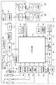
図1は、本発明のデータ処理装置が適用される撮像装置の構成を示すブロック図である。
(Circuit configuration of the imaging device)
FIG. 1 is a block diagram showing a configuration of an imaging apparatus to which a data processing apparatus of the present invention is applied.
図1において、100が撮像装置本体である。10は撮影レンズ、12は絞り機能を備えるシャッター、14は光学像を電気信号に変換する撮像素子(例えばCCD)、16は撮像素子14のアナログ信号出力をディジタル信号に変換するA/D変換器である。
In FIG. 1,
18は撮像素子14、 A/D変換器16、 D/A変換器26にクロック信号や制御信号を供給するタイミング発生回路であり、メモリ制御回路22及びシステム制御回路50により制御される。
A timing generation circuit 18 supplies a clock signal and a control signal to the
20は画像処理回路であり、 A/D変換器16からのデータ或いはメモリ制御回路22からのデータに対して所定の画素補間処理や色変換処理を行う。また、画像処理回路20においては、撮像した画像データを用いて所定の演算処理を行い、得られた演算結果に基づいてシステム制御回路50が露光制御部40、測距制御部42に対して制御を行う、TTL(スルー・ザ・レンズ)方式のAF(オートフォーカス)処理、AE(自動露出)処理、EF(フラッシュプリ発光)処理を行っている。さらに、画像処理回路20においては、撮像した画像データを用いて所定の演算処理を行い、得られた演算結果に基づいてTTL方式のAWB(オートホワイトバランス)処理も行っている。
An
22はメモリ制御回路であり、A/D変換器16、タイミング発生回路18、画像処理回路20、画像表示メモリ24、D/A変換器26、メモリ30、圧縮・伸長回路32を制御する。
A
A/D変換器16のデータが画像処理回路20、メモリ制御回路22を介して、或いはA/D変換器16のデータが直接メモリ制御回路22を介して、画像表示メモリ24或いはメモリ30に書き込まれる。
The data of the A /
24は画像表示メモリ、26はD/A変換器、28はTFT LCD等から成る画像表示部であり、画像表示メモリ24に書き込まれた表示用の画像データはD/A変換器26を介して画像表示部28により表示される。
画像表示部28を用いて撮像した画像データを逐次表示すれば、電子ファインダー機能を実現することが可能である。また、画像表示部28は、システム制御回路50の指示により任意に表示をON/OFFすることが可能であり、表示をOFFにした場合には画像処理装置100の電力消費を大幅に低減することが出来る。
If the image data captured using the
30は撮影した静止画像や動画像を格納するためのメモリであり、所定枚数の静止画像や所定時間の動画像を格納するのに十分な記憶量を備えている。これにより、複数枚の静止画像を連続して撮影する連射撮影やパノラマ撮影の場合にも、高速かつ大量の画像書き込みをメモリ30に対して行うことが可能となる。また、メモリ30はシステム制御回路50の作業領域としても使用することが可能である。
32は適応離散コサイン変換(ADCT)等により画像データを圧縮伸長する圧縮・伸長回路であり、メモリ30に格納された画像を読み込んで圧縮処理或いは伸長処理を行い、処理を終えたデータをメモリ30に書き込む。
40は絞り機能を備えるシャッター12を制御する露光制御部であり、フラッシュ48と連携することによりフラッシュ調光機能も有するものである。
42は撮影レンズ10のフォーカシングを制御する測距制御部、44は撮影レンズ10のズーミングを制御するズーム制御部、46は撮影レンズ10を保護するためのバリア102の動作を制御するバリア制御部である。48はフラッシュであり、AF補助光の投光機能、フラッシュ調光機能も有する。
露光制御部40、測距制御部42はTTL方式を用いて制御されており、撮像した画像データを画像処理回路20によって演算した演算結果に基づき、システム制御回路50が露光制御部40、測距制御部42に対して制御を行う。
The
50は撮像装置本体100の全体を制御するシステム制御回路、52はシステム制御回路50の動作用の定数、変数、プログラム等を記憶するメモリである。
54はシステム制御回路50でのプログラムの実行に応じて、文字、画像により動作状態やメッセージ等を表示するための液晶表示装置および、音声により動作状態やメッセージ等を報知するためのスピーカー等を含む表示部であり、撮像装置本体100の操作部近辺の視認し易い位置に単数或いは複数個所設置され、例えばLCDやLED、発音素子等の組み合わせにより構成されている。また、表示部54は、その一部の機能が光学ファインダー104内に設置されている。
54 includes a liquid crystal display device for displaying an operation state, a message, and the like by characters and images according to execution of a program in the
表示部54の表示内容のうち、LCD等に表示するものとしては、シングルショット/連写撮影表示、セルフタイマー表示、圧縮率表示、記録画素数表示、記録枚数表示、残撮影可能枚数表示、シャッタースピード表示、絞り値表示、露出補正表示、フラッシュ表示、赤目緩和表示、マクロ撮影表示、ブザー設定表示、時計用電池残量表示、電池残量表示、エラー表示、複数桁の数字による情報表示、記録媒体200及び210の着脱状態表示、通信I/F動作表示、日付け・時刻表示、等がある。
Among the display contents of the
また、表示部54の表示内容のうち、光学ファインダー104内に表示するものとしては、合焦表示、手振れ警告表示、フラッシュ充電表示、シャッタースピード表示、絞り値表示、露出補正表示、等がある。
Further, among the display contents of the
56は電気的に消去・記録可能な不揮発性メモリであり、例えばEEPROM等が用いられる。
60、62、64及び70は、システム制御回路50の各種の動作指示を入力するための操作手段であり、スイッチやダイアル、タッチパネル、視線検知によるポインティング、音声認識装置等の単数或いは複数の組み合わせで構成される。
ここで、これらの操作手段の具体的な説明を行う。 Here, a specific description of these operating means will be given.
60はモードダイアルスイッチで、自動撮影モード、撮影モード、パノラマ撮影モード、再生モード、マルチ画面再生・消去モード、PC接続モード等の各機能モードを切り替え設定することが出来る。
62はシャッタースイッチSW1で、図2に示されるシャッターボタン309の操作途中でONとなり、AF(オートフォーカス)処理、AE(自動露出)処理、AWB(オートホワイトバランス)処理、EF(フラッシュプリ発光)処理等の動作開始を指示する。
Reference numeral 62 denotes a shutter switch SW1, which is turned ON during the operation of the
64はシャッタースイッチSW2で、同シャッターボタン309の操作完了でONとなり、撮像素子14から読み出した信号をA/D変換器16、メモリ制御回路22を介してメモリ30に画像データを書き込む露光処理、画像処理回路20やメモリ制御回路22での演算を用いた現像処理、メモリ30から画像データを読み出し、圧縮・伸長回路32で圧縮を行い、記録媒体200或いは210に画像データを書き込む記録処理という一連の処理の動作開始を指示する。
70は各種ボタンやタッチパネル等からなる操作部で、図2に示すSETボタン302 、PLAYスイッチ303、上ボタン304、右ボタン305、下ボタン306、左ボタン307等を含む。
Reference numeral 70 denotes an operation unit including various buttons and a touch panel, and includes a
80は電源制御部で、電池検出回路、DC−DCコンバータ、通電するブロックを切り替えるスイッチ回路等により構成されており、電池の装着の有無、電池の種類、電池残量の計測を行い、検出結果及びシステム制御回路50の指示に基づいてDC−DCコンバータを制御し、必要な電圧を必要な期間、記録媒体を含む各部へ供給する。
A
82および84はコネクタ、86はアルカリ電池やリチウム電池等の一次電池やNiCd電池やNiMH電池、Li電池等の二次電池、ACアダプター等からなる電源装置である。 82 and 84 are connectors, 86 is a primary battery such as an alkaline battery or lithium battery, a secondary battery such as a NiCd battery, NiMH battery, or Li battery, an AC adapter, or the like.
90及び94はメモリカードやハードディスク等の記録媒体とのインタフェース、92及び96はメモリカードやハードディスク等の記録媒体と接続を行うコネクタ、98はコネクタ92及び或いは96に記録媒体200或いは210が装着されているか否かを検知する記録媒体着脱検知部である。
90 and 94 are interfaces with a recording medium such as a memory card or a hard disk, 92 and 96 are connectors for connecting to a recording medium such as a memory card or a hard disk, and 98 is a
なお、本実施形態では記録媒体を取り付けるインターフェース及びコネクタを2系統持つものとして説明している。もちろん、記録媒体を取り付けるインターフェース及びコネクタは、単数或いは複数、いずれの系統数を備える構成としても構わない。また、異なる規格のインターフェース及びコネクタを組み合わせて備える構成としても構わない。 In the present embodiment, it is assumed that there are two systems of interfaces and connectors for attaching a recording medium. Of course, the interface and the connector for attaching the recording medium may have a single or a plurality of systems and any number of systems. Moreover, it is good also as a structure provided with combining the interface and connector of a different standard.
インターフェース及びコネクタとしては、PCMCIAカードやCF(コンパクトフラッシュ(登録商標))カード等の規格に準拠したものを用いて構成して構わない。 The interface and connector may be configured using a PCMCIA card, a CF (Compact Flash (registered trademark)) card, or the like that conforms to a standard.
さらに、インタフェース90及び94、そしてコネクタ92及び96をPCMCIAカードやCF(コンパクトフラッシュ(登録商標))カード等の規格に準拠したものを用いて構成した場合、LANカードやモデムカード、USBカード、IEEE1394カード、P1284カード、SCSIカード、PHS等の通信カード、等の各種通信カードを接続することにより、他のコンピュータやプリンタ等の周辺機器との間で画像データや画像データに付属した管理情報を転送し合うことが出来る。
In addition, when the
102は、画像処理装置100のレンズ10を含む撮像部を覆うことにより、撮像部の汚れや破損を防止するためのバリアである。
104は光学ファインダーであり、画像表示部28による電子ファインダー機能を使用すること無しに、光学ファインダーのみを用いて撮影を行うことが可能である。また、光学ファインダー104内には、表示部54の一部の機能、例えば、合焦表示、手振れ警告表示、フラッシュ充電表示、シャッタースピード表示、絞り値表示、露出補正表示などが設置されている。
110は通信部で、RS232CやUSB、IEEE1394、SCSI、モデム、LAN、無線通信、等の各種通信機能を有する。112は通信部110により撮像装置本体100を他の機器と接続するコネクタ或いは無線通信の場合はアンテナである。
A
200はメモリカードやハードディスク等の記録媒体である。記録媒体200は、半導体メモリや磁気ディスク等から構成される記録部202、撮像装置本体100とのインタフェース204、画像処理装置100と接続を行うコネクタ206を備えている。210はメモリカードやハードディスク等の記録媒体である。記録媒体210は、半導体メモリや磁気ディスク等から構成される記録部212、撮像装置本体100とのインタフェース214、撮像装置本体100と接続を行うコネクタ216を備えている。
(撮像装置の外観構成)
図2は、本実施形態における撮像装置の背面を示す外観図である。図中301は図1に示した画像表示部28に相当する液晶パネルである。302〜307は図1の操作部70に含まれるスイッチまたはボタンである。具体的には、302は選択画像や設定を確定させる場合に使用するSETボタン、303は待機状態で押下すると撮像装置が再生モードで起動するPLAYスイッチ、304〜307はそれぞれ、再生画像の選択や画面に表示されたアイコンの選択等に使用する上下左右ボタンである。
(Appearance structure of imaging device)
FIG. 2 is an external view showing the back surface of the imaging apparatus according to the present embodiment. In the figure,
309は、撮影モード時に押下することにより画像を撮影するためのシャッターボタンで、シャッタースイッチSW1、SW2を含む構成である。
(ローバッテリー検知処理)
本実施形態における撮像装置の構成は概ね上記のとおりであるが、この撮像装置のシステムが起動すると、電源電圧が十分であるかどうかを確認するためのローバッテリー検知処理が行われる。
(Low battery detection processing)
The configuration of the imaging apparatus in the present embodiment is generally as described above, but when the system of the imaging apparatus is activated, a low battery detection process for confirming whether the power supply voltage is sufficient is performed.
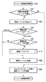
図8は、実施形態におけるローバッテリー検知処理を示すフローチャートである。撮像装置のシステムが起動すると、ローバッテリー検知処理が開始する(S40)。まず、ステップS41において、処理中断フラグを0に初期化する。次に、電源電圧計測を実施する(ステップS42)。計測した結果の電源電圧を所定の基準電圧(処理中断レベル)と比較する(ステップS43)。ここで電源電圧が処理中断レベル以上であれば、一定時間待機(Wait)し(ステップS44)、ステップS42に戻って再度電源電圧計測を繰り返す。一方、ステップS43において、電源電圧が処理中断レベルに達しない場合はステップS45に進み、処理中断フラグを立てる(処理中断フラグ=1)。ステップS45で処理中断フラグが1に設定されたとき、ローバッテリー検知処理は終了する(S46)。 FIG. 8 is a flowchart showing a low battery detection process in the embodiment. When the system of the imaging apparatus is activated, the low battery detection process starts (S40). First, in step S41, a process interruption flag is initialized to zero. Next, power supply voltage measurement is performed (step S42). The measured power supply voltage is compared with a predetermined reference voltage (processing interruption level) (step S43). Here, if the power supply voltage is equal to or higher than the processing interruption level, the system waits for a predetermined time (step S44), returns to step S42, and repeats the power supply voltage measurement. On the other hand, if the power supply voltage does not reach the process interruption level in step S43, the process proceeds to step S45, and a process interruption flag is set (processing interruption flag = 1). When the process interruption flag is set to 1 in step S45, the low battery detection process ends (S46).
このように、このローバッテリー検知処理における電源電圧計測は、システム起動時から処理中断フラグが1に設定されるまで継続的に行われる(ステップS42〜S44)。 As described above, the power supply voltage measurement in the low battery detection process is continuously performed from the start of the system until the process interruption flag is set to 1 (steps S42 to S44).
(動画編集時の操作方法)
次に、本実施形態における撮像装置で動画編集を行うために必要なユーザによる操作を説明する。
(Operation method when editing movies)
Next, an operation by a user necessary for editing a moving image with the imaging apparatus according to the present embodiment will be described.
(1) 再生モードでの起動
まず、PLAYスイッチ303を押下し、システムを再生モードで起動する。
(1) Start in playback mode First, the
(2) 編集対象動画の選択
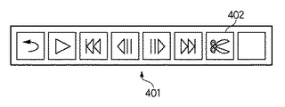
次に、左右キー307,305を操作し、編集したい動画画像を表示させ、SETボタン302を押下する。すると、液晶パネル301上に図3に示すような動画操作アイコン401が表示される。
(2) Selection of moving image to be edited Next, the left and
(3) 動画編集モードへ遷移
表示された動画操作アイコン401の編集モードアイコン402を選択し、その後、SETボタン302を押下して動画編集モードへ遷移させる。すると、液晶パネル301上に図4に示すような編集方法選択アイコンが表示される。
(3) Transition to moving image editing mode The
(4) 編集方法(例えばカット方法)の選択
指定位置の前側をカットしたい場合は、上下キー304,306を操作して、表示された編集方法選択アイコン501の前側カットアイコン503を選択し、指定位置の後ろ側をカットしたい場合は後半カットアイコン502を選択し、その後、SETボタン302を押下してより編集方法を決定する。すると、液晶パネル301上には図5に示すようなスライドバー601が表示される。
(4) Selection of editing method (for example, cutting method) When the front side of the specified position is to be cut, the up and down
(5) カット位置設定
左右キー307,305を操作し、編集動画上の編集位置を指定する。左右キー307,305の操作に応じて、スライドバー601上のインジケータ602が対応する位置に移動する。また、編集位置における動画データ先頭からの時間を時間表示部603に表示される。
(5) Cut position setting The left and
(6) 処理スタート(保存方法選択)
SETボタン302を押下し、編集処理を開始する。
(6) Start processing (save method selection)
Pressing the
(動画編集処理)
図6は、実施形態における撮像装置による動画編集処理を示すフローチャートである。
(Video editing process)
FIG. 6 is a flowchart illustrating a moving image editing process performed by the imaging apparatus according to the embodiment.
撮像装置100は、上記(3)での操作により動画編集モードに遷移すると、(2)で選択された動画ファイルを編集対象動画Aとして受け付け(ステップS11)、その編集対象動画ファイルAをオープンする(ステップS12)。次に、ファイルAの削除範囲を決定する(ステップS13)。具体的には、上記した(4)の編集方法の選択操作に応じて、指定位置の前側を削除するか後ろ側を削除するかを決定する。次に、上記した(5)のカット位置の設定操作に基づいて、編集対象動画ファイルAの編集対象位置の入力を受け付ける(ステップS21)。このとき、入力された選択フレーム番号を変数に保存しておく。次に、図7のフローチャートで示される編集サブルーチンS14を実行する(詳細は後述)。S14の編集サブルーチンの処理が終了すると、ステップS20で対象動画ファイルをクローズする。その後、エラーフラグをチェックする(ステップS15)。このエラーフラグは、後ほど詳しく説明するが、ローバッテリー検知処理により処理中断フラグが1に設定されたことに伴って1に設定される、というものである。このエラーフラグが0、すなわちエラーが発生していなければ、動画編集処理は正常に終了する(S17)。一方、エラーフラグが1、すなわち電源電圧低下によるエラーが発生していた場合は、エラー表示(ステップS19)、シャットダウン処理(ステップS16)を実施し、その後システムは停止する(S18)。
When the
以下、ステップS14の編集サブルーチンの処理について、図7のフローチャートを用いて説明する。このサブルーチンでは、動画ファイルAの一部を削除し新規ファイルBとして記録媒体200に書き込む処理を行う。
Hereinafter, the processing of the editing subroutine of step S14 will be described using the flowchart of FIG. In this subroutine, a process of deleting a part of the moving image file A and writing it to the
まず、ステップS31で、電源電圧の低下によるエラーを示すエラーフラグを0に初期化し、その後、ステップS22で編集結果ファイルBを新規にオープンする。 First, in step S31, an error flag indicating an error due to a drop in power supply voltage is initialized to 0, and then an editing result file B is newly opened in step S22.
次に、ステップS230において、上記した(4)においてユーザにより選択された編集方法を調べる。編集方法が後側削除の場合はステップS231に進む。ステップS231では、カレントフレーム番号として、編集対象ファイルAの動画データの先頭フレーム番号を設定する。また、終了フレーム番号としてステップS21で入力された選択フレーム番号を設定する。他方、ステップS230で調べた編集方法が前側削除の場合は、ステップS232へ進む。ステップS232では、カレントフレーム番号として選択フレーム番号を設定し、終了フレーム番号として編集対象ファイルAの動画データの最終フレーム番号を設定する。 Next, in step S230, the editing method selected by the user in (4) described above is checked. If the editing method is rear deletion, the process proceeds to step S231. In step S231, the first frame number of the moving image data of the editing target file A is set as the current frame number. Also, the selected frame number input in step S21 is set as the end frame number. On the other hand, if the editing method checked in step S230 is the front side deletion, the process proceeds to step S232. In step S232, the selected frame number is set as the current frame number, and the final frame number of the moving image data of the editing target file A is set as the end frame number.
次に、ステップS24で、編集対象動画ファイルAからカレントフレーム番号に対応するフレームの画像データを読み出す。そしてステップS25に進み、読み出した画像データを編集結果ファイルBに書き込む。次に、ステップS26で、カレントフレーム番号をインクリメントする。 Next, in step S24, image data of a frame corresponding to the current frame number is read from the editing target moving image file A. In step S25, the read image data is written in the editing result file B. Next, in step S26, the current frame number is incremented.
次に、ステップS27において、動画編集処理の中断フラグをチェックする。この中断フラグは、前述のローバッテリー検知処理において設定されるものである。ここで、中断フラグが立っていない場合(中断フラグ=0の場合)はステップS28へ進む。ステップS28では、カレントフレーム番号が終了フレーム番号を超えているかどうかチェックする。条件に当てはまった場合は、ステップS29へ進み、編集結果ファイルBのファイルヘッダーおよびフッター等を作成することによって動画ファイルとしてのフォーマットを整える。続くステップS30では、作成した編集結果ファイルBをクローズし、編集サブルーチンを抜ける(S32)。 Next, in step S27, the interruption flag of the moving image editing process is checked. This interruption flag is set in the low battery detection process described above. Here, when the interruption flag is not set (when interruption flag = 0), the process proceeds to step S28. In step S28, it is checked whether or not the current frame number exceeds the end frame number. If the condition is met, the process proceeds to step S29, and the file header and footer of the editing result file B are created to prepare the format as a moving image file. In the subsequent step S30, the created editing result file B is closed and the editing subroutine is exited (S32).
ステップS28において、条件が成立しなかった場合、すなわち、カレントフレーム番号が終了フレーム番号を超えていないときは、ステップS24へ戻り、処理を繰り返す。 If the condition is not satisfied in step S28, that is, if the current frame number does not exceed the end frame number, the process returns to step S24 and the process is repeated.
また、ステップS27において、処理中断フラグが立っていた場合(処理中断フラグ=1の場合)はステップS37に進み、エラーフラグを立てる(エラーフラグ=1)とともに、処理中断フラグを0にリセットする。その後、ステップS38において、編集結果ファイルBの書き込み処理を完了するために要する時間(残処理時間)Trを計算する。このTrの計算は例えば次式に従い行う。 In step S27, when the process interruption flag is set (when the process interruption flag = 1), the process proceeds to step S37, an error flag is set (error flag = 1), and the process interruption flag is reset to zero. Thereafter, in step S38, a time (remaining processing time) Tr required to complete the writing process of the editing result file B is calculated. The calculation of Tr is performed according to the following equation, for example.
Tr=ファイルBの未書き込みデータサイズ/単位データ量あたりの書き込み所要時間
ここで、単位データ量あたりの書き込み所要時間は、使用する記録媒体が変更されるごとに計測し、その値を保持しておくものとする。
Tr = File B unwritten data size / time required for writing per unit data amount Here, the time required for writing per unit data amount is measured each time the recording medium to be used is changed, and the value is stored. I shall keep it.
次に、ステップS391に進み、電源電圧をチェックし、その結果、電源電圧がローバッテリー検知処理において行われる処理中断判定時の基準よりさらに低い緊急レベルを下回った場合はステップS392へ進む。ステップS392では、編集結果ファイルBをクローズし、続くステップS393で、ファイル修復に必要な情報である元ファイルAのファイル名、ユーザが指定した編集方法、ユーザが指定した編集位置を示す選択フレーム番号(すなわち、編集対象位置)、カレントフレーム番号(すなわち、処理中止時点における元ファイルAの読み出し位置)、編集結果ファイルBのファイル名を、システム固有のファイル名をつけた情報ファイルCへ格納し、編集サブルーチンを抜ける(S32)。 Next, the process proceeds to step S391, where the power supply voltage is checked. As a result, if the power supply voltage falls below the emergency level that is lower than the criterion at the time of process interruption determination performed in the low battery detection process, the process proceeds to step S392. In step S392, the editing result file B is closed, and in the subsequent step S393, the file name of the original file A, which is information necessary for file restoration, the editing method specified by the user, and the selected frame number indicating the editing position specified by the user (Namely, the position to be edited), the current frame number (that is, the reading position of the original file A at the time when the process was stopped), and the file name of the editing result file B are stored in the information file C with a system-specific file name, The editing subroutine is exited (S32).
一方、ステップS391において、電源電圧が緊急レベル以上ある場合はステップS39へ進む。ステップS39では、編集結果ファイルBの書き込み処理を完了するために要する時間Trと、それまでに書き込んだ編集結果ファイルBを削除するのに要する時間Tdを比較する。ここで、編集結果ファイルBの書き込み処理を完了するために要する時間Trが、一部書き込み済みの編集結果ファイルBを削除するのに要する時間Tdより長い場合は、ステップS35に進み、途中まで書き込んでいた編集結果ファイルBをクローズし、続くステップS36において、クローズした編集結果ファイルBを削除して、編集サブルーチンを抜ける(S32)。 On the other hand, if the power supply voltage is higher than the emergency level in step S391, the process proceeds to step S39. In step S39, the time Tr required to complete the writing process of the editing result file B is compared with the time Td required to delete the editing result file B written so far. Here, if the time Tr required to complete the writing process of the editing result file B is longer than the time Td required to delete the partially written editing result file B, the process proceeds to step S35 and writing is performed halfway. The edited editing result file B is closed, and in the subsequent step S36, the closed editing result file B is deleted and the editing subroutine is exited (S32).
また、ステップS39において、一部書き込み済みの編集結果ファイルBを削除するのに要する時間Tdが、編集処理を完了するのに要する時間Tr以上あると判定された場合は、ステップS28へ進み、上述した処理を継続する。 If it is determined in step S39 that the time Td required to delete the partially written editing result file B is equal to or longer than the time Tr required to complete the editing process, the process proceeds to step S28. Continue the process.
ここで、ファイルBを削除するのに要する時間Tdの推定方法を説明しておく。ファイルシステムとしてFAT(ファイル・アロケーション・テーブル)ファイルシステムを使用している場合、ファイルを削除するのに要する時間はそのファイルに対応するFATとファイル属性等を管理しているディレクトリエントリを削除する時間の合計となる。したがって、ファイルBを削除するのに要する時間Tdは例えば次式により求められる。 Here, a method for estimating the time Td required to delete the file B will be described. When a FAT (File Allocation Table) file system is used as the file system, the time required to delete the file is the time required to delete the directory entry that manages the FAT and file attributes corresponding to the file. It becomes the sum of. Accordingly, the time Td required to delete the file B is obtained by the following equation, for example.
Td=(ファイルBのFATに使用しているクラスタ数+ディレクトリエントリに使用しているクラスタ数)*使用している記録媒体における1クラスタのあたりのデータ書き込み所要時間
ここで、1クラスタあたりのデータ書き込み所要時間は、使用する記録媒体が変更されるごとに計測し、その値を保持しておくものとする。
Td = (number of clusters used for FAT of file B + number of clusters used for directory entry) * time required for data writing per cluster in the recording medium used Here, data per cluster The time required for writing is measured each time the recording medium to be used is changed, and the value is held.
本実施形態における動画編集処理は上記のとおりである。なお、上記したステップS39では、編集処理を完了するのに要する時間と、途中まで書き込み済みの編集結果ファイルBを削除するのに要する時間とを比較して、その編集結果ファイルBを削除するかどうか選択する方法を採用したが、削除するかどうかを、ユーザーによって選択する方法をとることも可能である。 The moving image editing process in the present embodiment is as described above. In step S39, whether the editing result file B is deleted by comparing the time required to complete the editing process with the time required to delete the editing result file B that has been written halfway. Although the method of selecting whether or not is adopted, it is also possible to adopt a method of selecting whether or not to delete by the user.
(ファイル修復)
次に、図9のフローチャートを用いて、本実施形態におけるファイル修復処理について説明する。
(File repair)
Next, the file restoration process in the present embodiment will be described using the flowchart of FIG.
このファイル修復処理は、システムがPLAYモードで起動されたときに開始される(S60)。まず、ステップS61において、編集中断時に作成された中断情報ファイルCが、記録媒体200に存在するかどうかを調べる。中断情報ファイルCが記録媒体200に存在しない場合、記録媒体200の動画ファイルを調べ、対応するサムネール画像が存在しないものについてはこれを削除する(ステップS62)。
This file repair process is started when the system is activated in the PLAY mode (S60). First, in step S61, it is checked whether or not the interruption information file C created at the time of editing interruption exists in the
ステップS61において、編集中断情報ファイルCが存在した場合、ステップS63へ進み、この中断情報ファイルCを読み取ることにより、編集対象ファイルAのファイル名、ユーザが指定した編集方法、ユーザが指定した編集位置を示す選択フレーム番号、カレントフレーム番号、編集結果ファイルBのファイル名についての情報を読み出す。 If the editing interruption information file C exists in step S61, the process proceeds to step S63, and the interruption information file C is read to read the file name of the editing target file A, the editing method specified by the user, and the editing position specified by the user. Information about the selected frame number, the current frame number, and the file name of the editing result file B are read out.
次に、ステップS64において、編集対象ファイルAをオープンする。その結果がエラーだった場合は、編集処理中断情報ファイルCの削除を行い(ステップS66)、対応するサムネール画像が存在しないものについてはこれを削除し(ステップS62)、ファイル修復処理を完了する。 Next, in step S64, the editing target file A is opened. If the result is an error, the editing process interruption information file C is deleted (step S66). If the corresponding thumbnail image does not exist, it is deleted (step S62), and the file repair process is completed.
一方、ステップS64において、編集対象ファイルAのオープンに成功した場合はステップS65に進み、編集結果ファイルBの有無を調査し、無ければ上記と同様にステップS66で中断情報ファイルCを削除を行い、対応するサムネール画像が存在しないものについてはこれを削除し(ステップS62)、ファイル修復処理を完了する。 On the other hand, if the editing target file A is successfully opened in step S64, the process proceeds to step S65, where the presence or absence of the editing result file B is checked. If there is no corresponding thumbnail image, it is deleted (step S62), and the file repair process is completed.
ステップS65において、編集結果ファイルBが存在した場合は、図7に示したステップS14の編集サブルーチンを実行する。この編集サブルーチンを完了すると、編集処理中断情報ファイルCの削除を行い(ステップS66)、対応するサムネール画像が存在しないものについてはこれを削除し(ステップS62)、ファイル修復処理を完了する。 If the editing result file B exists in step S65, the editing subroutine of step S14 shown in FIG. 7 is executed. When this editing subroutine is completed, the editing process interruption information file C is deleted (step S66). If the corresponding thumbnail image does not exist, it is deleted (step S62), and the file restoration process is completed.
以上の処理により、従来取り扱うことのできなかった編集途中の動画ファイルを記録媒体から消去することが可能となる。 Through the above processing, it is possible to delete a moving image file being edited that could not be handled in the past from the recording medium.
(他の実施形態)
以上、本発明の実施形態を詳述したが、本発明は、複数の機器から構成されるシステムに適用してもよいし、また、一つの機器からなる装置に適用してもよい。
(Other embodiments)
As mentioned above, although embodiment of this invention was explained in full detail, this invention may be applied to the system comprised from several apparatuses, and may be applied to the apparatus which consists of one apparatus.
なお、本発明は、前述した実施形態の機能を実現するソフトウェアのプログラムを、システムあるいは装置に直接あるいは遠隔から供給し、そのシステムあるいは装置のコンピュータがその供給されたプログラムコードを読み出して実行することによっても達成される。その場合、プログラムの機能を有していれば、その形態はプログラムである必要はない。 In the present invention, a software program that realizes the functions of the above-described embodiments is directly or remotely supplied to a system or apparatus, and the computer of the system or apparatus reads and executes the supplied program code. Is also achieved. In that case, as long as it has the function of a program, the form does not need to be a program.
従って、本発明の機能処理をコンピュータで実現するために、そのコンピュータにインストールされるプログラムコード自体およびそのプログラムを格納した記憶媒体も本発明を構成することになる。つまり、本発明の特許請求の範囲には、本発明の機能処理を実現するためのコンピュータプログラム自体、およびそのプログラムを格納した記憶媒体も含まれる。 Therefore, in order to realize the functional processing of the present invention with a computer, the program code itself installed in the computer and the storage medium storing the program also constitute the present invention. In other words, the claims of the present invention include the computer program itself for realizing the functional processing of the present invention and a storage medium storing the program.
その場合、プログラムの機能を有していれば、オブジェクトコード、インタプリタにより実行されるプログラム、OSに供給するスクリプトデータ等、プログラムの形態を問わない。 In this case, the program may be in any form as long as it has a program function, such as an object code, a program executed by an interpreter, or script data supplied to the OS.
プログラムを供給するための記憶媒体としては、例えば、フレキシブルディスク、ハードディスク、光ディスク、光磁気ディスク、MO、CD−ROM、CD−R、CD−RW、磁気テープ、不揮発性のメモリカード、ROM、DVD(DVD−ROM,DVD−R)などがある。 As a storage medium for supplying the program, for example, flexible disk, hard disk, optical disk, magneto-optical disk, MO, CD-ROM, CD-R, CD-RW, magnetic tape, nonvolatile memory card, ROM, DVD (DVD-ROM, DVD-R).
その他、プログラムの供給方法としては、クライアントコンピュータのブラウザを用いてインターネットのホームページに接続し、そのホームページから本発明のコンピュータプログラムそのもの、もしくは圧縮され自動インストール機能を含むファイルをハードディスク等の記憶媒体にダウンロードすることによっても供給できる。また、本発明のプログラムを構成するプログラムコードを複数のファイルに分割し、それぞれのファイルを異なるホームページからダウンロードすることによっても実現可能である。つまり、本発明の機能処理をコンピュータで実現するためのプログラムファイルを複数のユーザに対してダウンロードさせるWWWサーバも、本発明のクレームに含まれるものである。 As another program supply method, a client computer browser is used to connect to an Internet homepage, and the computer program of the present invention itself or a compressed file including an automatic installation function is downloaded from the homepage to a storage medium such as a hard disk. Can also be supplied. It can also be realized by dividing the program code constituting the program of the present invention into a plurality of files and downloading each file from a different homepage. That is, a WWW server that allows a plurality of users to download a program file for realizing the functional processing of the present invention on a computer is also included in the claims of the present invention.
また、本発明のプログラムを暗号化してCD−ROM等の記憶媒体に格納してユーザに配布し、所定の条件をクリアしたユーザに対し、インターネットを介してホームページから暗号化を解く鍵情報をダウンロードさせ、その鍵情報を使用することにより暗号化されたプログラムを実行してコンピュータにインストールさせて実現することも可能である。 In addition, the program of the present invention is encrypted, stored in a storage medium such as a CD-ROM, distributed to users, and key information for decryption is downloaded from a homepage via the Internet to users who have cleared predetermined conditions. It is also possible to execute the encrypted program by using the key information and install the program on a computer.
また、コンピュータが、読み出したプログラムを実行することによって、前述した実施形態の機能が実現される他、そのプログラムの指示に基づき、コンピュータ上で稼動しているOSなどが、実際の処理の一部または全部を行い、その処理によっても前述した実施形態の機能が実現され得る。 In addition to the functions of the above-described embodiments being realized by the computer executing the read program, the OS running on the computer based on the instruction of the program is a part of the actual processing. Alternatively, the functions of the above-described embodiment can be realized by performing all of them and performing the processing.
さらに、記憶媒体から読み出されたプログラムが、コンピュータに挿入された機能拡張ボードやコンピュータに接続された機能拡張ユニットに備わるメモリに書き込まれた後、そのプログラムの指示に基づき、その機能拡張ボードや機能拡張ユニットに備わるCPUなどが実際の処理の一部または全部を行い、その処理によっても前述した実施形態の機能が実現される。 Furthermore, after the program read from the storage medium is written to a memory provided in a function expansion board inserted into the computer or a function expansion unit connected to the computer, the function expansion board or The CPU or the like provided in the function expansion unit performs part or all of the actual processing, and the functions of the above-described embodiments are realized by the processing.
10:撮影レンズ
12:シャッター
14:撮像素子
16:A/D変換器
18:タイミング発生回路
20:画像処理回路
22:メモリ制御回路
24:画像表示メモリ
26:D/A変換器
28:画像表示部
30:メモリ
32:画像圧縮・伸長回路
40:露光制御部
42:測距制御部
44:ズーム制御部
46:バリア制御部
48:フラッシュ
50:システム制御回路
52:メモリ
54:表示部
56:不揮発性メモリ
60:モードダイアルスイッチ
62:シャッタースイッチSW1
64:シャッタースイッチSW2
70:操作部
80:電源制御部
82:コネクタ
84:コネクタ
86:電源
90:インタフェース
92:コネクタ
94:インタフェース
96:コネクタ
98:記録媒体着脱検知部
100:撮像装置本体
102:バリア
104:光学ファインダー
110:通信部
112:コネクタ(またはアンテナ)
200:記録媒体
202:記録部
204:インタフェース
206:コネクタ
210:記録媒体
212:記録部
214:インタフェース
216:コネクタ
301: 液晶パネル
302: SETボタン
303: PLAYスイッチ
304: 上ボタン
305: 右ボタン
306: 下ボタン
307: 左ボタン
309: シャッターボタン
401: 動画操作アイコン
402: 編集モードアイコン
501: 編集方法選択アイコン
502: 後側カットアイコン
503: 前側カットアイコン
601: 編集位置指定スライドバー
602: 編集位置インジケータ
603: 編集位置時間表示部
DESCRIPTION OF SYMBOLS 10: Shooting lens 12: Shutter 14: Image pick-up element 16: A / D converter 18: Timing generation circuit 20: Image processing circuit 22: Memory control circuit 24: Image display memory 26: D / A converter 28: Image display part 30: Memory 32: Image compression / decompression circuit 40: Exposure control unit 42: Distance measurement control unit 44: Zoom control unit 46: Barrier control unit 48: Flash 50: System control circuit 52: Memory 54: Display unit 56: Non-volatile Memory 60: Mode dial switch 62: Shutter switch SW1
64: Shutter switch SW2
70: operation unit 80: power supply control unit 82: connector 84: connector 86: power supply 90: interface 92: connector 94: interface 96: connector 98: recording medium attachment / detachment detection unit 100: imaging device main body 102: barrier 104: optical viewfinder 110 : Communication unit 112: Connector (or antenna)
200: Recording medium 202: Recording unit 204: Interface 206: Connector 210: Recording medium 212: Recording unit 214: Interface 216: Connector 301: Liquid crystal panel 302: SET button 303: PLAY switch 304: Up button 305: Right button 306: Down button 307: Left button 309: Shutter button 401: Movie operation icon 402: Edit mode icon 501: Edit method selection icon 502: Rear cut icon 503: Front cut icon 601: Edit position designation slide bar 602: Edit position indicator 603 : Edit position time display
Claims (11)
前記記録媒体より読み出した第1のファイルを編集し、その編集結果を第2のファイルとして生成する編集手段と、Editing means for editing the first file read from the recording medium and generating the edited result as a second file;
前記第2のファイルの前記記録媒体への書き込み処理中における電源電圧を検知する検知手段と、Detecting means for detecting a power supply voltage during the process of writing the second file to the recording medium;
を有し、Have
前記検知手段により検知された電源電圧が第1のしきい値を下回っている場合であって、かつ前記編集手段による編集が完了するまでの時間が前記記憶媒体に既に書き込まれた第2のファイルに係るデータを削除する時間よりも長い場合、前記制御手段は、前記第2のファイルの書き込み処理を中止させるとともに、前記記録媒体に既に書き込まれた前記第2のファイルに係るデータを削除し、A second file in which the power supply voltage detected by the detecting means is below a first threshold and the time until the editing by the editing means is completed is already written to the storage medium If it is longer than the time to delete the data related to, the control means stops the writing process of the second file and deletes the data related to the second file already written to the recording medium,
前記検知手段により検知された電源電圧が第1のしきい値を下回っている場合であって、かつ前記編集手段による編集が完了するまでの時間が前記記憶媒体に既に書き込まれた第2のファイルに係るデータを削除する時間よりも短い場合、前記制御手段は、前記第2のファイルの書き込み処理を続行するA second file in which the power supply voltage detected by the detecting means is below a first threshold and the time until the editing by the editing means is completed is already written to the storage medium If it is shorter than the time to delete the data related to the, the control means continues the writing process of the second file
ことを特徴とするデータ編集装置。A data editing apparatus characterized by that.
前記修復手段は、前記第3のファイルから前記第1のファイルのファイル名を読み出して当該第1のファイルをオープンし、前記第3のファイルから前記編集方法、編集対象位置、前記制御手段による書き込み処理の中止時点における前記第1のファイルの読み出し位置、前記第2のファイルのファイル名、に基づいて、前記編集手段を動作させることを特徴とする請求項6に記載のデータ編集装置。 The third file includes a file name of the first file, an editing method, an editing target position, a reading position of the first file when the writing process is stopped by the control unit, and a file name of the second file. Including information necessary for deleting the data related to the second file,
The restoration means reads the file name of the first file from the third file, opens the first file, and writes the editing method, editing target position, and writing by the control means from the third file. The data editing apparatus according to claim 6, wherein the editing unit is operated based on a read position of the first file and a file name of the second file at the time when the process is stopped.
前記制御手段は、前記撮像手段により得られた画像データを前記記録媒体に記録することを特徴とする請求項1乃至8のいずれか1項に記載のデータ編集装置。9. The data editing apparatus according to claim 1, wherein the control unit records image data obtained by the imaging unit on the recording medium.
編集手段が、前記記録媒体より読み出した第1のファイルを編集し、その編集結果を第2のファイルとして生成する編集ステップと、An editing step of editing the first file read from the recording medium and generating the editing result as a second file;
検知手段が、前記第2のファイルの前記記録媒体への書き込み処理中における電源電圧を検知する検知ステップと、A detecting step for detecting a power supply voltage during the process of writing the second file to the recording medium;
を有し、Have
前記検知ステップで検知された電源電圧が第1のしきい値を下回っている場合であって、かつ前記編集ステップにおける編集が完了するまでの時間が前記記憶媒体に既に書き込まれた第2のファイルに係るデータを削除する時間よりも長い場合、前記制御ステップでは、前記第2のファイルの書き込み処理を中止させるとともに、前記記録媒体に既に書き込まれた前記第2のファイルに係るデータを削除し、A second file in which the power supply voltage detected in the detection step is lower than a first threshold and the time until the editing in the editing step is completed is already written in the storage medium If it is longer than the time to delete the data related to, the control step stops the writing process of the second file and deletes the data related to the second file already written to the recording medium,
前記検知ステップで検知された電源電圧が第1のしきい値を下回っている場合であって、かつ前記編集ステップにおける編集が完了するまでの時間が前記記憶媒体に既に書き込まれた第2のファイルに係るデータを削除する時間よりも短い場合、前記制御ステップでは、前記第2のファイルの書き込み処理を続行するA second file in which the power supply voltage detected in the detection step is lower than a first threshold and the time until the editing in the editing step is completed is already written in the storage medium If it is shorter than the time to delete the data relating to the second step, the control step continues the writing process of the second file
ことを特徴とするデータ編集方法。A data editing method characterized by that.
Priority Applications (1)
| Application Number | Priority Date | Filing Date | Title |
|---|---|---|---|
| JP2004020384A JP4208730B2 (en) | 2004-01-28 | 2004-01-28 | Data editing apparatus and method, and imaging apparatus |
Applications Claiming Priority (1)
| Application Number | Priority Date | Filing Date | Title |
|---|---|---|---|
| JP2004020384A JP4208730B2 (en) | 2004-01-28 | 2004-01-28 | Data editing apparatus and method, and imaging apparatus |
Publications (3)
| Publication Number | Publication Date |
|---|---|
| JP2005216359A JP2005216359A (en) | 2005-08-11 |
| JP2005216359A5 JP2005216359A5 (en) | 2007-03-15 |
| JP4208730B2 true JP4208730B2 (en) | 2009-01-14 |
Family
ID=34904320
Family Applications (1)
| Application Number | Title | Priority Date | Filing Date |
|---|---|---|---|
| JP2004020384A Expired - Fee Related JP4208730B2 (en) | 2004-01-28 | 2004-01-28 | Data editing apparatus and method, and imaging apparatus |
Country Status (1)
| Country | Link |
|---|---|
| JP (1) | JP4208730B2 (en) |
Families Citing this family (2)
| Publication number | Priority date | Publication date | Assignee | Title |
|---|---|---|---|---|
| JP2012175281A (en) * | 2011-02-18 | 2012-09-10 | Sharp Corp | Video recording apparatus and television receiver |
| JP2015076693A (en) * | 2013-10-08 | 2015-04-20 | 株式会社リコー | Display device, display system, and program |
-
2004
- 2004-01-28 JP JP2004020384A patent/JP4208730B2/en not_active Expired - Fee Related
Also Published As
| Publication number | Publication date |
|---|---|
| JP2005216359A (en) | 2005-08-11 |
Similar Documents
| Publication | Publication Date | Title |
|---|---|---|
| JP4809960B2 (en) | Image processing apparatus, method, and recording medium | |
| JP4541459B2 (en) | Digital camera | |
| US8643761B2 (en) | Camera and control method of camera | |
| JP4603985B2 (en) | Imaging apparatus, imaging method, and control program | |
| US20120176512A1 (en) | Image storage apparatus, image storage method, and control program executed in image storage apparatus | |
| JP4324116B2 (en) | Image processing apparatus, control method therefor, program, and storage medium | |
| JP5064686B2 (en) | IMAGING DEVICE, CONTROL METHOD FOR THE DEVICE, CONTROL PROGRAM, AND RECORDING MEDIUM | |
| JP4700796B2 (en) | Imaging apparatus, control method therefor, and storage medium | |
| JP4208730B2 (en) | Data editing apparatus and method, and imaging apparatus | |
| JP2007221272A (en) | Imaging apparatus and method of controlling same | |
| JP2007036587A (en) | Imaging apparatus and its control method | |
| JP4124885B2 (en) | Image playback device | |
| JP4560189B2 (en) | Imaging device | |
| JP2002218382A (en) | Image processor and data processing method thereof | |
| JP4298534B2 (en) | Image display apparatus and method | |
| JP2006157884A (en) | Display control device and display control method | |
| JP4701297B2 (en) | Image processing apparatus, method, and recording medium | |
| JP4717762B2 (en) | Image reproducing apparatus, control method for image reproducing apparatus, program, and recording medium | |
| JP4766706B2 (en) | Image processing apparatus, control method therefor, program, and storage medium | |
| JP4776967B2 (en) | RECORDING / REPRODUCING DEVICE, ITS CONTROL METHOD, PROGRAM, AND STORAGE MEDIUM | |
| JP2011066806A (en) | Image processor | |
| JP4865202B2 (en) | File transfer apparatus, program, and computer-readable recording medium | |
| JP2008072443A (en) | Image processing apparatus and image processing method | |
| JP2006202051A (en) | Data processor and data processing method | |
| JP2008040351A (en) | Information processor, screen layout method, and program |
Legal Events
| Date | Code | Title | Description |
|---|---|---|---|
| A521 | Request for written amendment filed |
Free format text: JAPANESE INTERMEDIATE CODE: A523 Effective date: 20070129 |
|
| A621 | Written request for application examination |
Free format text: JAPANESE INTERMEDIATE CODE: A621 Effective date: 20070129 |
|
| A131 | Notification of reasons for refusal |
Free format text: JAPANESE INTERMEDIATE CODE: A131 Effective date: 20080630 |
|
| A521 | Request for written amendment filed |
Free format text: JAPANESE INTERMEDIATE CODE: A523 Effective date: 20080826 |
|
| TRDD | Decision of grant or rejection written | ||
| A01 | Written decision to grant a patent or to grant a registration (utility model) |
Free format text: JAPANESE INTERMEDIATE CODE: A01 Effective date: 20080926 |
|
| A01 | Written decision to grant a patent or to grant a registration (utility model) |
Free format text: JAPANESE INTERMEDIATE CODE: A01 |
|
| A61 | First payment of annual fees (during grant procedure) |
Free format text: JAPANESE INTERMEDIATE CODE: A61 Effective date: 20081021 |
|
| R150 | Certificate of patent or registration of utility model |
Free format text: JAPANESE INTERMEDIATE CODE: R150 |
|
| FPAY | Renewal fee payment (event date is renewal date of database) |
Free format text: PAYMENT UNTIL: 20111031 Year of fee payment: 3 |
|
| FPAY | Renewal fee payment (event date is renewal date of database) |
Free format text: PAYMENT UNTIL: 20111031 Year of fee payment: 3 |
|
| FPAY | Renewal fee payment (event date is renewal date of database) |
Free format text: PAYMENT UNTIL: 20121031 Year of fee payment: 4 |
|
| FPAY | Renewal fee payment (event date is renewal date of database) |
Free format text: PAYMENT UNTIL: 20131031 Year of fee payment: 5 |
|
| LAPS | Cancellation because of no payment of annual fees |