JP4207643B2 - Seat slide device - Google Patents
Seat slide device Download PDFInfo
- Publication number
- JP4207643B2 JP4207643B2 JP2003115992A JP2003115992A JP4207643B2 JP 4207643 B2 JP4207643 B2 JP 4207643B2 JP 2003115992 A JP2003115992 A JP 2003115992A JP 2003115992 A JP2003115992 A JP 2003115992A JP 4207643 B2 JP4207643 B2 JP 4207643B2
- Authority
- JP
- Japan
- Prior art keywords
- lower rail
- slide device
- rail
- bolt
- seat
- Prior art date
- Legal status (The legal status is an assumption and is not a legal conclusion. Google has not performed a legal analysis and makes no representation as to the accuracy of the status listed.)
- Expired - Fee Related
Links
Images


Description
【0001】
【発明が属する技術分野】
本発明は、車両用シートをフロアに対して、摺動可能にして位置を調整できるように支持するシートスライド装置に関する。特に、シートスライド装置を車両に容易にしかも強固に取付け可能としたシートスライド装置に関する。
【0002】
【従来の技術】
リクレーショナルビークル等で、リヤシートを車両の前後に位置を大きく移動させて、乗員の着座スペースとか荷物スペースを大きくするために、長いロアレールを備えるシートスライド装置が利用される。このようなシートスライド装置では、所定の取付け強度を確保できるように長いロアレールをフロアに装着する必要がある。このために、従来、ロアレールを両端部のみならず、長手方向の中間部分の複数箇所にもロアレールの側面にブラケットを溶接等で取付け、ブラケットをボルトでフロアに締付ける方法が行われている。(例えば、特許文献1参照。)。
【0003】
【特許文献1】
特開平10-016612号公報
【0004】
【発明が解決しようとする課題】
上記した従来の技術によるシートスライド装置の構成では、ブラケットをロアレールに溶接で取付ける際、ロアレールに熱による歪が発生しやすく、シートスライド装置の円滑な位置調整機能を得るのが難しくなる。また、この構成では複数のブラケットを用意する必要があって部品の点数も増え、製造コストのアップを招いていた。更に車両へのシートスライド装置の固定の際は、組付けラインに多くのボルトを用意して置く必要があって煩雑になっていた。
【0005】
このことから、本発明の課題は、ブラケット等のように溶接して取付ける別部品を用意することなくロアレールの中間部分もフロアに強固に固定可能とする構成を有するとともに、シートスライド装置を車両に組付ける際のボルトによって煩雑になるのを防ぎ、安価にできるようにすることである。
【0006】
【課題を解決するための手段】
上記した課題を解決するために、本発明で講じた第一の技術的な手段は、車両のフロア側にボルトを用い固定して装着されるロアレールと、該ロアレールと摺動自在に係合してシートを支えるアッパレールと、前記アッパレールを前記ロアレールに係止可能とするロック機構を有するシートスライド装置において、前記ロアレールに形成された複数の穴に挿通されるボルトと、前記ロアレールが前記フロアに装着される前に予め該ボルトを前記ロアレールに係止させる係止部材を備え、前記ロアレールは、車両のフロアに当接するとともに前記複数の穴が透設された平面部と、前記アッパレールに対して円滑に摺動可能とすべく該アッパレールとの間に配設された転動部材を囲うように、前記平面部の両側端から上方に延び且つその上端から内方に屈曲しつつ前記アッパレールを挿入可能な所定間隔を空けて下方に折り返された係合部とを有し、前記係止部材は、前記平面部と前記係合部との間に配置され、その幅が前記係合部の前記所定間隔よりも広く設定されるとともに、該平面部の上方側から前記穴に挿通される前記ボルトと螺合するネジ部が形成されたワッシャを有することである。
【0007】
この構成によって、車両へのシートスライド装置の組付けが、多くのボルトによって煩雑になることが無く、しかも長いロアレールが車両フロア側に複数箇所で固定が容易になりシートスライド装置を強固にことができるようになる。
【0009】
また、シートスライド装置を車両に装着する前でも、確実にボルトをロアレールに係止させて置くことが可能となる。
【0011】
加えて、ロアレールの断面形状はボルトが挿通可能な大きさで構成が可能となって、小型にできる。
更に、本発明で講じた第2の技術的な手段は、第1手段に加えて、前記ワッシャの両側端に、上方に向かって幅広となるように斜め上方に延びるフランジを形成したことである。
更に、本発明で講じた第3の技術的な手段は、第1手段または第2手段に加えて、前記係止部材は、前記平面部の下方側に配置され、前記ワッシャの前記ネジ部に螺合し且つ前記穴に挿通された前記ボルトに螺合することにより、前記ワッシャとの間で該平面部を上下に挟む止め輪を備えることである。
【0012】
【発明の実施の形態】
以下、本発明に関するシートスライド装置20について図面を参照にして詳述する。
【0013】
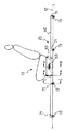
図1は、本発明に係るシートスライド装置20を備えるシート10を示す。シート10はシートスライド装置20によって、車両のフロア12上に位置調整が可能に装着される。シートスライド装置20は、フロア12に固定されるロアレール40と、シート10に取付けられアッパレール30を備え、アッパレール30はロアレール40に対して摺動可能に構成されている。
【0014】
例えば、位置を移動して乗員の着座スペースとか荷物スペースを大きく変更するようにして利用されるリクエーショナルビークルのリヤシートでは、シート10の位置を大きく移動できるように、移動方向に長く延びるロアレール40が採用される。このような長いロアレール40をフロア12に所定の取付け強度を確保して装着するためには、図1に示されるように、ロアレール40は、その両端部のみならず、長手方向の中間部分でも複数のボルト71を用いてフロア12に締付ける方法が採られる。
【0015】
図2に示されるように、アッパレール30は上端部に形成された平面部31でシート10を支持している。更に、平面部31の両端から下方に側面部32が延びて形成され、側面部32の夫々の下端はU字形状に曲げられ係合部33が形成されている。係合部33には対の軸63が溶接等で外側方向に水平に延びるように取付けられ、軸63にはベアリング62が取付けられている。
【0016】
図2に更に示されるように、ロアレール40は、下端にフロア12に当接する平面部41を有し、平面部41の両端から上方に延びる部分は、ベアリング62を囲む概略矩形形状となる対の係合部42を形成している。所定の間隔を開けて配置された対の係合部42の間から、アッパレール30がロアレール40断面内に挿入され、ベアリング62が係合部42の矩形形状の下面42a上を転動する構成となっている。また係合部42の矩形形状の上面はアッパレール30がロアレール40から外れないように係合する構成となっている。そして、アッパレール30はロアレール40に案内されて円滑に摺動できる構成となっている。
【0017】
図1及び図3に示すように、シートスライド装置20は、アッパレール30のロアレール40に対する位置を調整可能にするために、互いの位置をロック又はロック解除するロック機構50を備える。ロック機構50は、アッパレール30の側面部32に固定して取付けられたブラケット56と、ブラケット56にピン55で回転自在に取付けられたロックレバー52を備える。ロックレバー52はその回転中心となるピン55との結合部分から下方に伸び、その下端部には、係止爪部53が形成されている。係止爪部53は、アッパレール30のU字型係合部33の内側に形成された係止穴34、ロアレール40の係合部42に形成されたロック穴44、更にはU字型係合部33の外側に形成された係止穴35を貫通する。図3に示されるように、係止爪部53が各穴34、43、35を貫通して係止しているとき、アッパレール30とロアレール40は互にロックされ、シート10はフロア12に対して移動できない。
【0018】
ロックレバー52は、図示されないバネ部品の作用で、アッパレール30とロアレール40を互にロックする図3に示す状態に保持される。また、バネ力に抗してロックレバー53を図3において時計方向に回転させて、係止爪部53を各穴34、43、35から外すことによって、ロックが解除される。ロックレバー53の解除作動は、上端部52aを直接手動で操作するか、または上端部52aに別途ケーブル等を取付け、遠隔操作で下方に引き下ろす方法が採られる。ロアレール40のロック穴44はロアレール40の長手方向に所定の間隔をもって、複数配置されている。そして、ロック穴44の位置でアッパレール30をロックして調整位置に固定できる構成となっている。
【0019】
前述のように、ロアレール40は複数のボルト71で、フロア12に固定されている。図4、図5及び図6に示すようにボルト71は最も大きい径を持つ頭部73と、頭部73の下方に小径部74、更に小径部74の下方にネジ部72、そして最下端に小径部75を備えるように成形されている。ネジ部72を挟む両側の小径部74、75は、ネジ部72のネジ谷底径より小さい径に設定されている。
【0020】
図4は、ロアレール40をフロア12に取付ける前の状態を示し、図5は取付け後の状態を示している。図4の取付ける前の状態では、ボルト71はロアレール40の平面部41に設けられた穴43に挿通され、平面部41を上下に挟むように設置されたワッシャ84(係止部材)及び止め輪81(係止部材)で保持されている。
【0021】
ワッシャ84はロアレール40の平面部41に当接する平面部を有し、その中央に穴87が形成されている。穴87の内径には雌ネジ88が形成されて、ボルト71のネジ部72と螺合している。一方、止め輪81も平面形状でその中央部分に穴部83を備える。穴部83の内径には突起するように複数の爪82a、82b、82cが形成されている。各爪82a、82b、82cは夫々が平面部分に対して上下方向に対して折り曲げられネジ部72のネジピッチに適合し、ボルト71のネジ部72に螺合する雌ネジの機能を持つようになっている。図4の状態のとき、ボルト71の下端部にワッシャ84と止め輪81が螺合し、且つワッシャ84と止め輪81で平面部41を上下に挟むようにしている。車両にシートスライド装置20が組み付けられる前に、予めロアレール40に取付けられたボルト71は、輸送する途中でもロアレール40から外れてしまうことがなく保持される構成となっている。
【0022】
このように構成されたシートスライド装置20を組付けラインで車両に、ボルト71を締付けロアレール40をフロア12に固定するとき、先ずシートスライド装置20をフロア12上に置き、ボルト71の下端部の小径部75を、フロア12の穴15と穴15と同心にフロア12の下面に溶接されたナット14のネジ穴14aに嵌めて位置決する。ロアレール40に複数に取付けられたボルト71の小径部75が夫々対応するフロア12の穴15に確実に嵌ったことを確認された後に、所定の工具でボルト71をナット14に締付け、図5に示される状態にする。特にこの作業で、図4の締付け前はボルト71の頭部73は、ロアレール40の上面とほぼ同じ高さ位置になるように設定されているため、締付け工具をボルト71の頭部73に容易に合わせることができる。図5の締付け後の状態では、ワッシャ84は、ボルト71のネジの無い小径部74の位置で嵌って、ボルト71に対して回転自在となる。そして、ボルト71は強固にナット14に締付けられる。
【0023】
上記に構成で、例えば図4でよく分かるように、ロアレール40の断面形状で、対の係合部42の間隔は、ボルト71の頭部73が挿入される幅であれば良く、ロアレール40を小型に形成できる利点がある。
【0024】
以上のように構成された、シートスライド装置20は、シート10の位置を大きく移動するように作用できる。更に、例えば図1に示されるようにロアレール40のほぼ中間位置にアッパレール30がロックされて使用されているときに、シート10に大きな衝撃力が作用するような緊急な場合にも、ロアレール40はフロア12に複数のボルト71で、強固に固定されているために所定の強度が確保される。
【0025】
【発明の効果】
以上の本発明に関わるシートスライド装置20の構成でによって、車両のフロア12へのシートスライド装置20の組付けが、多くのボルト71によって煩雑になることが無く、しかも長いロアレールが車両フロア側に複数箇所で固定が容易になりシートスライド装置を強固にことができるようになる。
【図面の簡単な説明】
【図1】本発明に係るシートスライド装置を備えるシート本体の側面図である。
【図2】図1におけるA−A断面図である。
【図3】図1におけるB−B断面図である。
【図4】図1におけるC−C断面図で、ボルトの締付け前の状態を示す。
【図5】図1におけるC−C断面図で、ボルトの締付け後の状態を示す。。
【図6】本発明に係るシートスライド装置のボルトとロアレールの一部分を示す分解斜視図である。
【符号の説明】
12 フロア
30 アッパレール
40 ロアレール
41 平面部
43 穴
50 ロック機構
71 ボルト
81 係止部材(止め輪)
85 係止部材(ワッシャ)
82a、82b、82c ネジ部(爪)
88 ネジ部(雌ネジ)[0001]
[Technical field to which the invention belongs]
The present invention relates to a seat slide device that supports a vehicle seat so that the position of the vehicle seat can be adjusted with respect to a floor. In particular, the present invention relates to a seat slide device that can be easily and firmly attached to a vehicle.
[0002]
[Prior art]
A seat slide device having a long lower rail is used to greatly increase the seating space or luggage space of the occupant by moving the position of the rear seat back and forth in the front and rear of the vehicle with a recreational vehicle or the like. In such a seat slide device, it is necessary to attach a long lower rail to the floor so as to ensure a predetermined mounting strength. For this reason, conventionally, a method has been used in which the lower rail is attached to the side surfaces of the lower rail not only at both ends but also at a plurality of longitudinal intermediate portions by welding or the like, and the bracket is fastened to the floor with bolts. (For example, see Patent Document 1).
[0003]
[Patent Document 1]
Japanese Patent Laid-Open No. 10-016612
[Problems to be solved by the invention]
In the structure of the seat slide device according to the conventional technique described above, when the bracket is attached to the lower rail by welding, distortion due to heat is likely to occur in the lower rail, and it is difficult to obtain a smooth position adjusting function of the seat slide device. Further, in this configuration, it is necessary to prepare a plurality of brackets, and the number of parts increases, leading to an increase in manufacturing cost. Furthermore, when the seat slide device is fixed to the vehicle, it is necessary to prepare many bolts on the assembly line, which is complicated.
[0005]
Therefore, the object of the present invention is to have a configuration in which the intermediate portion of the lower rail can be firmly fixed to the floor without preparing a separate part to be welded and attached, such as a bracket, and the seat slide device is mounted on the vehicle. It is to be able to prevent it from becoming complicated by the bolts when assembling and to make it inexpensive.
[0006]
[Means for Solving the Problems]
In order to solve the above-described problems, the first technical means taken in the present invention includes a lower rail that is fixedly mounted on the floor side of a vehicle using a bolt, a slidably engaged with the lower rail. A seat slide device having an upper rail that supports the seat and a lock mechanism that allows the upper rail to be locked to the lower rail, and a bolt that is inserted into a plurality of holes formed in the lower rail, and the lower rail is attached to the floor A locking member for previously locking the bolt to the lower rail before being pushed, and the lower rail is in contact with the floor of the vehicle and is smooth with respect to the flat portion through which the plurality of holes are formed and the upper rail. So as to surround the rolling member disposed between the upper rail and the upper rail. An engaging portion that is bent downward and spaced downward with a predetermined interval into which the upper rail can be inserted, and the locking member is disposed between the planar portion and the engaging portion, The width of the engaging portion is set wider than the predetermined interval, and a washer having a screw portion screwed with the bolt inserted into the hole from above the flat portion is provided. .
[0007]
With this configuration, the assembly of the seat slide device to the vehicle is not complicated by many bolts, and the long lower rail can be easily fixed to the vehicle floor at a plurality of locations, and the seat slide device can be strengthened. become able to.
[0009]
Further, even before the seat slide device is mounted on the vehicle, the bolt can be securely locked and placed on the lower rail.
[0011]
In addition, the cross-sectional shape of the lower rail can be configured with a size that allows bolts to be inserted, and can be made compact.
Furthermore, the second technical means taken in the present invention is that, in addition to the first means, flanges extending obliquely upward are formed at both side ends of the washer so as to become wider upward. .
Further, according to a third technical means taken in the present invention, in addition to the first means or the second means, the locking member is disposed on the lower side of the flat portion, and is attached to the screw portion of the washer. It is provided with a retaining ring for vertically sandwiching the flat portion with the washer by screwing and screwing into the bolt inserted into the hole.
[0012]
DETAILED DESCRIPTION OF THE INVENTION
Hereinafter, the
[0013]
FIG. 1 shows a
[0014]
For example, in a rear seat of a recreational vehicle that is used by moving its position to greatly change the seating space or luggage space of the occupant, a
[0015]
As shown in FIG. 2, the
[0016]
As further shown in FIG. 2, the
[0017]
As shown in FIGS. 1 and 3, the
[0018]
The
[0019]
As described above, the
[0020]
4 shows a state before the
[0021]
The washer 84 has a flat portion that contacts the
[0022]
When the
[0023]
In the above configuration, for example, as can be seen in FIG. 4, the cross-sectional shape of the
[0024]
The
[0025]
【The invention's effect】
With the above-described configuration of the
[Brief description of the drawings]
FIG. 1 is a side view of a seat body including a seat slide device according to the present invention.
FIG. 2 is a cross-sectional view taken along the line AA in FIG.
3 is a cross-sectional view taken along line BB in FIG.
4 is a cross-sectional view taken along the line CC in FIG. 1, showing a state before the bolt is tightened.
FIG. 5 is a cross-sectional view taken along the line CC in FIG. 1 and shows a state after the bolt is tightened. .
FIG. 6 is an exploded perspective view showing a part of the bolt and lower rail of the seat slide device according to the present invention.
[Explanation of symbols]
12
85 Locking member (washer)
82a, 82b, 82c Screw part (nail)
88 Screw part (Female thread)
Claims (3)
前記ロアレールに形成された複数の穴に挿通されるボルトと、前記ロアレールが前記フロアに装着される前に予め該ボルトを前記ロアレールに係止させる係止部材を備え、
前記ロアレールは、車両のフロアに当接するとともに前記複数の穴が透設された平面部と、前記アッパレールに対して円滑に摺動可能とすべく該アッパレールとの間に配設された転動部材を囲うように、前記平面部の両側端から上方に延び且つその上端から内方に屈曲しつつ前記アッパレールを挿入可能な所定間隔を空けて下方に折り返された係合部とを有し、
前記係止部材は、前記平面部と前記係合部との間に配置され、その幅が前記係合部の前記所定間隔よりも広く設定されるとともに、該平面部の上方側から前記穴に挿通される前記ボルトと螺合するネジ部が形成されたワッシャを有することを特徴とするシートスライド装置。A lower rail that is fixedly mounted on a vehicle floor using bolts, an upper rail that slidably engages with the lower rail to support the seat, and a seat that has a lock mechanism that can lock the upper rail to the lower rail. In the slide device,
A bolt inserted into a plurality of holes formed in the lower rail, and a locking member for previously locking the bolt to the lower rail before the lower rail is mounted on the floor ,
The lower rail is a rolling member that is disposed between a flat portion that is in contact with the floor of the vehicle and through which the plurality of holes are formed, and the upper rail so that the lower rail can slide smoothly with respect to the upper rail. An engagement portion that extends upward from both side ends of the flat surface portion and is bent downward from the upper end thereof while being bent inwardly and folded downward with a predetermined interval into which the upper rail can be inserted.
The locking member is disposed between the planar portion and the engaging portion, and the width thereof is set wider than the predetermined interval of the engaging portion, and the hole is formed from above the planar portion into the hole. A seat slide device comprising a washer having a threaded portion that is screwed into the bolt to be inserted .
Priority Applications (1)
| Application Number | Priority Date | Filing Date | Title |
|---|---|---|---|
| JP2003115992A JP4207643B2 (en) | 2003-04-21 | 2003-04-21 | Seat slide device |
Applications Claiming Priority (1)
| Application Number | Priority Date | Filing Date | Title |
|---|---|---|---|
| JP2003115992A JP4207643B2 (en) | 2003-04-21 | 2003-04-21 | Seat slide device |
Publications (2)
| Publication Number | Publication Date |
|---|---|
| JP2004322678A JP2004322678A (en) | 2004-11-18 |
| JP4207643B2 true JP4207643B2 (en) | 2009-01-14 |
Family
ID=33496381
Family Applications (1)
| Application Number | Title | Priority Date | Filing Date |
|---|---|---|---|
| JP2003115992A Expired - Fee Related JP4207643B2 (en) | 2003-04-21 | 2003-04-21 | Seat slide device |
Country Status (1)
| Country | Link |
|---|---|
| JP (1) | JP4207643B2 (en) |
Families Citing this family (2)
| Publication number | Priority date | Publication date | Assignee | Title |
|---|---|---|---|---|
| WO2016031018A1 (en) * | 2014-08-28 | 2016-03-03 | ジョンソン コントロールズ テクノロジー カンパニ- | Seat slide device for vehicle |
| JP7376042B2 (en) | 2019-12-18 | 2023-11-08 | トヨタ紡織精工株式会社 | seat sliding device |
-
2003
- 2003-04-21 JP JP2003115992A patent/JP4207643B2/en not_active Expired - Fee Related
Also Published As
| Publication number | Publication date |
|---|---|
| JP2004322678A (en) | 2004-11-18 |
Similar Documents
| Publication | Publication Date | Title |
|---|---|---|
| US8245994B2 (en) | Seat apparatus for vehicle | |
| US7048244B2 (en) | Seat track assembly and method of manufacture | |
| US20190047477A1 (en) | Extruded support members for facilitating access to a vehicle and related methods | |
| EP2241477A1 (en) | Passenger's weight measurement device for vehicle seat | |
| KR101834994B1 (en) | Locking unit for a vehicle seat, and vehicle seat | |
| JP5788216B2 (en) | Cushion seat frame structure for vehicle seat and vehicle seat having the structure | |
| JPH07195964A (en) | Device for adjusting car seat fore and aft | |
| JP2009502629A (en) | Bracket system specially designed for fixing the seat position | |
| JP4207643B2 (en) | Seat slide device | |
| JP2008054715A (en) | Vehicle seat | |
| JP2003341469A (en) | Shoulder adjuster device | |
| US5083735A (en) | Vehicle seat | |
| JP2838103B2 (en) | Car seat adjuster | |
| JP5365225B2 (en) | Slide structure for vehicle seat | |
| US20140013876A1 (en) | Actuating device for a locking device of an adjusting device of a motor vehicle seat | |
| JP4924139B2 (en) | Seat belt buckle mounting structure | |
| JP5487750B2 (en) | Vehicle seat locking device | |
| JP4482496B2 (en) | Seat fastening structure | |
| JP3836769B2 (en) | Vehicle seat device | |
| JP3844127B2 (en) | Vehicle seat slide device | |
| WO2012096083A1 (en) | Lock unit for vehicle | |
| JP2508158Y2 (en) | Sheet slide device | |
| JP2023126430A (en) | Vehicular seat device | |
| JP2556794Y2 (en) | Lock mechanism for seat slide device | |
| JP3137453U (en) | Bicycle saddle anti-theft device |
Legal Events
| Date | Code | Title | Description |
|---|---|---|---|
| A621 | Written request for application examination |
Free format text: JAPANESE INTERMEDIATE CODE: A621 Effective date: 20060320 |
|
| A977 | Report on retrieval |
Free format text: JAPANESE INTERMEDIATE CODE: A971007 Effective date: 20080626 |
|
| A131 | Notification of reasons for refusal |
Free format text: JAPANESE INTERMEDIATE CODE: A131 Effective date: 20080701 |
|
| A521 | Written amendment |
Free format text: JAPANESE INTERMEDIATE CODE: A523 Effective date: 20080825 |
|
| TRDD | Decision of grant or rejection written | ||
| A01 | Written decision to grant a patent or to grant a registration (utility model) |
Free format text: JAPANESE INTERMEDIATE CODE: A01 Effective date: 20080930 |
|
| A01 | Written decision to grant a patent or to grant a registration (utility model) |
Free format text: JAPANESE INTERMEDIATE CODE: A01 |
|
| A61 | First payment of annual fees (during grant procedure) |
Free format text: JAPANESE INTERMEDIATE CODE: A61 Effective date: 20081013 |
|
| R151 | Written notification of patent or utility model registration |
Ref document number: 4207643 Country of ref document: JP Free format text: JAPANESE INTERMEDIATE CODE: R151 |
|
| FPAY | Renewal fee payment (event date is renewal date of database) |
Free format text: PAYMENT UNTIL: 20111031 Year of fee payment: 3 |
|
| FPAY | Renewal fee payment (event date is renewal date of database) |
Free format text: PAYMENT UNTIL: 20121031 Year of fee payment: 4 |
|
| FPAY | Renewal fee payment (event date is renewal date of database) |
Free format text: PAYMENT UNTIL: 20121031 Year of fee payment: 4 |
|
| FPAY | Renewal fee payment (event date is renewal date of database) |
Free format text: PAYMENT UNTIL: 20131031 Year of fee payment: 5 |
|
| LAPS | Cancellation because of no payment of annual fees |