JP4206756B2 - Identification of printing recording material container - Google Patents
Identification of printing recording material container Download PDFInfo
- Publication number
- JP4206756B2 JP4206756B2 JP2002542621A JP2002542621A JP4206756B2 JP 4206756 B2 JP4206756 B2 JP 4206756B2 JP 2002542621 A JP2002542621 A JP 2002542621A JP 2002542621 A JP2002542621 A JP 2002542621A JP 4206756 B2 JP4206756 B2 JP 4206756B2
- Authority
- JP
- Japan
- Prior art keywords
- recording material
- material container
- printing recording
- ink cartridge
- printing
- Prior art date
- Legal status (The legal status is an assumption and is not a legal conclusion. Google has not performed a legal analysis and makes no representation as to the accuracy of the status listed.)
- Expired - Fee Related
Links
Images


Classifications
-
- B—PERFORMING OPERATIONS; TRANSPORTING
- B41—PRINTING; LINING MACHINES; TYPEWRITERS; STAMPS
- B41J—TYPEWRITERS; SELECTIVE PRINTING MECHANISMS, i.e. MECHANISMS PRINTING OTHERWISE THAN FROM A FORME; CORRECTION OF TYPOGRAPHICAL ERRORS
- B41J2/00—Typewriters or selective printing mechanisms characterised by the printing or marking process for which they are designed
- B41J2/005—Typewriters or selective printing mechanisms characterised by the printing or marking process for which they are designed characterised by bringing liquid or particles selectively into contact with a printing material
- B41J2/01—Ink jet
- B41J2/17—Ink jet characterised by ink handling
- B41J2/175—Ink supply systems ; Circuit parts therefor
- B41J2/17503—Ink cartridges
- B41J2/17543—Cartridge presence detection or type identification
- B41J2/17546—Cartridge presence detection or type identification electronically
-
- B—PERFORMING OPERATIONS; TRANSPORTING
- B41—PRINTING; LINING MACHINES; TYPEWRITERS; STAMPS
- B41J—TYPEWRITERS; SELECTIVE PRINTING MECHANISMS, i.e. MECHANISMS PRINTING OTHERWISE THAN FROM A FORME; CORRECTION OF TYPOGRAPHICAL ERRORS
- B41J2/00—Typewriters or selective printing mechanisms characterised by the printing or marking process for which they are designed
- B41J2/005—Typewriters or selective printing mechanisms characterised by the printing or marking process for which they are designed characterised by bringing liquid or particles selectively into contact with a printing material
- B41J2/01—Ink jet
- B41J2/17—Ink jet characterised by ink handling
- B41J2/175—Ink supply systems ; Circuit parts therefor
- B41J2/17566—Ink level or ink residue control
Abstract
Description
技術分野
本発明は、印刷装置における印刷記録材容器の識別技術に関し、さらに詳細には印刷記録材容器交換に際して正しい印刷記録材容器が装着されたか否かを識別する技術に関する。
発明の背景
複数色のインクカートリッジ(印刷記録材容器)を備えるカラープリンタにおいて、インクカートリッジの交換時におけるインクカートリッジの誤装着、すなわち、交換されるべきインク色とは異なるインクカートリッジの装着、を防止するための技術が提案されている。例えば、インク色毎にインクカートリッジの外形形状を変更し、誤ったインクカートリッジが物理的に装着できないようにする技術が知られている。
また、同一の外形形状を有するインクカートリッジを用いる場合には、一個のインクカートリッジのみが脱着可能な開口部を有するカバーをプリンタ上に設け、交換されるべきインクカートリッジを開口部まで移動させて、交換されるべきインクカートリッジのみの脱着を許容する技術が知られている。
しかしながら、インク色毎に異なる外形形状を有するインクカートリッジを用いる場合には、インクカートリッジを再利用する際にインク色毎にしかインクカートリッジを再利用することができず、リサイクル効率が悪いという問題があった。また、インクカートリッジの誤装着は防止できても交換を要しないインクカートリッジを誤まって取り外してしまうという問題は防止することができなかった。さらに、インク色毎にインクカートリッジ用の異なる金型を作成しなければならず、コスト高になるという問題があった。
インクカートリッジを所定の交換位置まで移動させる技術では、交換されるべきでないインクカートリッジの誤った取り外しは防止できても、装着されたインクカートリッジが正しいインクカートリッジであるか否かまでは検出することはできず、誤装着は防止できないという問題があった。
発明の開示
本発明は、上記問題を解決するためになされたものであり、外形的な識別形状を用いることなく印刷記録材容器交換時における印刷記録材容器の誤装着を防止することを目的とする。また、交換されるべきでない印刷記録材容器の誤った取り外しを防止することを目的とする。
上記課題を解決するために本発明の第1の態様は、識別情報を格納する記憶装置を有すると共に印刷装置に装着される印刷記録材容器の識別装置を提供する。本発明の第1の態様に係る印刷記録材容器の識別装置は、前記記憶装置に格納されている識別情報を利用して、前記装着された印刷記録材容器が装着されるべき正しい印刷記録材容器であるか否かを判定する判定手段とを備えることを特徴とする。
本発明の第1の態様に係る印刷記録材容器の識別装置によれば、記憶装置に格納されている識別情報を利用して、装着された印刷記録材容器が装着されるべき正しい印刷記録材容器であるか否かを判定するので、外形的な識別形状を用いることなく印刷記録材容器交換時における印刷記録材容器の誤装着を検出することができる。なお、外形的な識別形状が同時に用いられ得ることはいうまでもない。
本発明の第1の態様に係る印刷記録材容器の識別装置はさらに、前記判定手段によって、前記装着された印刷記録材容器が装着されるべき正しい印刷記録材容器でないと判定された場合には、誤った印刷記録材容器が装着された旨を報知する報知手段を備えても良い。かかる構成を備える場合には、誤った印刷記録材容器の装着をユーザに対して報知することが可能となり、早期に正しい印刷記録材容器の装着を促すことができる。
本発明の第1の態様に係る印刷記録材容器の識別装置はさらに、前記判定手段によって、前記装着された印刷記録材容器が装着されるべき正しい印刷記録材容器であるか否か判定されるまで前記印刷記録材容器中の印刷記録材の吸引を禁止する吸引禁止手段を備えても良い。かかる構成を備える場合には、誤った印刷記録材容器が装着された際に、誤った印刷記録材を吸引することに起因する印刷品質の低下を未然に防止することができる。
本発明の第1の態様に係る印刷記録材容器の識別装置において、前記印刷装置には複数の印刷記録材容器が既定の装着位置にそれぞれ装着されており、前記判定手段は、前記各装着位置に装着されるべき印刷記録材容器と前記装着位置とを関連付ける装着位置情報を有し、前記装着された印刷記録材容器に装着されている記憶装置の識別情報と前記装着位置情報とに基づいて、前記装着された印刷記録材容器が装着されるべき正しい印刷記録材容器であるか否かを判定しても良い。かかる構成を備える場合には、装着位置情報と、印刷記録材容器が装着された際の識別情報とに基づいて、正しい印刷記録材容器が装着されたか否かを判定することができる。
本発明の第1の態様に係る印刷記録材容器の識別装置において、前記判定手段は、前記記憶装置に格納されている識別情報を利用して、前記印刷記録材容器の取り外しが検出された場合には前記取り外された印刷記録材容器を特定すると共に、前記印刷記録材容器の装着が検出された場合には、前記装着された印刷記録材容器の識別情報を用いて前記装着された印刷記録材容器が前記取り外された印刷記録材容器と同一または交換が許容される印刷記録材を内包する印刷記録材容器であるか否かを判定しても良い。かかる場合には、取り外された印刷記録材容器と同一の印刷記録材容器のみならず、取り外された印刷記録材容器と交換が許容される印刷記録材容器を利用する場合にも正しい印刷記録材容器が装着されたか否かを判定することができる。
本発明の第1の態様に係る印刷記録材容器の識別装置において、前記判定手段は、前記印刷装置には複数の印刷記録材容器が装着されており、前記記憶装置に格納されている識別情報を利用して、前記印刷記録材容器の取り外しが検出された場合には前記取り外された印刷記録材容器を特定すると共に、前記印刷記録材容器の装着が検出された場合には前記装着された印刷記録材容器を特定し、その特定結果に基づいて、前記装着された印刷記録材容器が前記取り外された印刷記録材容器と同一の印刷記録材を内包する印刷記録材容器であるか否かを判定しても良い。かかる構成を備える場合には、装着位置情報を有し得ない場合であっても、取り外された印刷記録材容器の識別情報と、装着された印刷記録材容器の識別情報とに基づいて、正しい印刷記録材容器が装着されたか否かを判定することができる。
本発明の第1の態様に係る印刷記録材容器の識別装置において、前記複数の印刷記録材容器に備えられている各記憶装置は、格納している識別情報に対応する識別信号を受信した場合にのみ応答し、前記判定手段は、前記印刷記録材容器の取り外しが検出された後に、前記各記憶装置に対して全ての識別情報に対応する識別信号を送信し、応答の得られなかった記憶装置を備える印刷記録材容器を前記取り外された印刷記録材容器として特定し、前記印刷記録材容器の装着が検出された後に、前記応答の得られなかった記憶装置が格納する識別情報に対応する識別信号を前記各記憶装置に対して送信し、応答が得られた場合には、正しい印刷記録材容器が装着されたことを判定しても良い。かかる構成を備える場合には、印刷記録材容器に備えられている記憶装置からの応答の有無によって正しい印刷記録材容器が装着されたか否かを判定することができる。また、識別情報を用いて交換されるべきでない印刷記録材容器の誤った取り外しを検出することがかのうとなり、結果として印刷記録材容器の誤った取り外しを防止するこができる。
本発明の第1の態様に係る印刷記録材容器の識別装置において、前記判定手段は、前記応答の得られなかった記憶装置が格納する識別情報に対応する識別信号を前記各記憶装置に対して送信し、応答が得られなかった場合には、誤った印刷記録材容器が装着されたことを判定しても良い。
本発明の第1の態様に係る印刷記録材容器の識別装置はさらに、前記各記憶装置をカスケードに接続すると共に一端が接地され且つ他端が記憶装置検出電圧に接続されている記憶装置検出信号線と、前記記憶装置検出信号線の値に基づいて印刷記録材容器の脱着を検出する脱着検出手段とを備えても良い。かかる場合には、検出電圧の値に基づいて印刷記録材容器の脱着を検出することができる。
本発明の第2の態様は、印刷記録材の種類に対応する識別情報を格納する記憶装置を備えると共に印刷装置に装着される印刷記録材容器の識別方法を提供する。本発明の第2の態様に係る印刷記録材容器の識別方法は、前記印刷記録材容器の取り外しを検出し、前記記憶装置に格納されている識別情報を利用して、前記取り外された印刷記録材容器の印刷記録材の種類を識別し、前記印刷記録材容器の装着を検出し、前記記憶装置に格納されている識別情報を利用して、前記装着された印刷記録材容器の印刷記録材の種類を識別し、前記装着された印刷記録材容器の印刷記録材の種類の識別結果と、前記取り外された印刷記録材容器の印刷記録材の種類の識別結果とに基づいて、正しい印刷記録材容器が装着されたか否かを判定することを特徴とする。
本発明の第2の態様に係る印刷記録材容器の識別方法によれば、記憶装置に格納されている識別情報を利用して、装着された印刷記録材容器が装着されるべき正しい印刷記録材容器であるか否かを判定するので、外形的な識別形状を用いることなく印刷記録材容器交換時における印刷記録材容器の誤装着を検出することができる。
本発明の第2の態様に係る印刷記録材容器の識別方法において、前記装着された印刷記録材容器の印刷記録材の種類と前記取り外された印刷記録材容器の印刷記録材の種類とが同一または交換が許容される種類の場合には、正しい印刷記録材容器が装着されたものと判定しても良い。また、前記装着された印刷記録材容器の印刷記録材の種類と前記取り外された印刷記録材容器の印刷記録材の種類とが異なる場合には、誤った印刷記録材容器が装着されたものと判定し、誤った印刷記録材容器の装着を報知しても良い。
本発明の第2の態様に係る印刷記録材容器の識別方法において、前記装着された印刷記録材容器が装着されるべき正しい印刷記録材容器であるか否か判定されるまで前記印刷記録材容器中の印刷記録材の吸引を禁止しても良い。かかる構成を備える場合には、誤った印刷記録材容器が装着された際に、誤った印刷記録材を吸引することに起因する印刷品質の低下を未然に防止することができる。
本発明の第3の態様は、印刷記録材の種類に対応する識別情報を格納する記憶装置を備えると共に前記印刷記録材の種類に応じて印刷装置上に既定の位置に装着される印刷記録材容器の識別方法を提供する。本発明の第3の態様に係る印刷記録材容器の識別方法は、前記印刷記録材容器の取り外しを検出し、前記取り外された印刷記録材容器が装着されていた装着位置を記憶し、前記印刷記録材容器の装着を検出し、前記記憶装置に格納されている識別情報を利用して、前記装着された印刷記録材容器の印刷記録材の種類を識別し、前記装着された印刷記録材容器の装着位置と、前記装着された印刷記録材容器の印刷記録材の種類とに基づいて、正しい印刷記録材容器が装着されたか否かを判定しても良い。
本発明の第3の態様に係る印刷記録材容器の識別方法によれば、取り外された印刷記録材容器の装着位置と、記憶装置に格納されている識別情報を利用して、装着された印刷記録材容器が装着されるべき正しい印刷記録材容器であるか否かを判定するので、外形的な識別形状を用いることなく印刷記録材容器交換時における印刷記録材容器の誤装着を検出することができる。
本発明の第3の態様に係る印刷記録材容器の識別方法において、誤った印刷記録材容器が装着されたものと判定した場合には、誤った印刷記録材容器の装着を報知しても良い。
本発明の第4の態様は、印刷記録材の種類に対応する識別情報を格納する記憶装置を備えると共に印刷記録材の種類に応じて印刷装置上に既定の位置に装着される印刷記録材容器の交換を監視するプログラムを記録したコンピュータ読み取り可能媒体を提供する。本発明の第4の態様に係るコンピュータ読み取り可能な記録媒体は、前記印刷記録材容器の取り外しを検出する機能と、前記取り外された印刷記録材容器が装着されていた装着位置を記憶する機能と、前記印刷記録材容器の装着を検出する機能と、前記記憶装置に格納されている識別情報を利用して、前記装着された印刷記録材容器の印刷記録材の種類を識別する機能と、前記装着された印刷記録材容器の装着位置と、前記装着された印刷記録材容器の印刷記録材の種類とに基づいて、正しい印刷記録材容器が装着されたか否かを判定する機能とをコンピュータに実行させるプログラムを備えることを特徴とする。
本発明の第4の態様に係るコンピュータ読み取り可能媒体によれば、本発明の第2の態様に係る印刷記録材容器の識別方法と同様の効果を得ることができる。
本発明の第5の態様は、収容されている印刷記録材の種類に対応した識別情報を格納する記憶装置を有する複数の印刷記録材容器が装着される印刷装置における印刷記録材容器の交換制御装置を提供する。本発明の第5の態様に係る印刷記録材容器の交換制御装置は、印刷記録材の交換要求を検出する交換要求検出手段と、前記交換の要求された印刷記録材を内包する印刷記録材容器を交換位置まで移動させる印刷記録材容器移動手段と、前記交換位置に移動された前記印刷記録材容器の取り外しを検出すると共に、取り外しに続く印刷記録材容器の装着を検出する脱着検出手段と、前記識別情報を利用して、前記装着された印刷記録材容器が交換の要求された印刷記録材を内包する正しい印刷記録材容器であるか否かを判定する判定手段とを備えることを特徴とする。
本発明の第5の態様に係る印刷記録材容器の交換制御装置によれば、記憶装置に格納されている識別情報を利用して、装着された印刷記録材容器が装着されるべき正しい印刷記録材容器であるか否かを判定するので、外形的な識別形状を用いることなく印刷記録材容器交換時における印刷記録材容器の誤装着を検出することができる。
本発明の第5の態様に係る印刷記録材容器の交換制御装置において、前記印刷装置は、前記印刷記録材を用いて印刷を実行する印刷手段と、前記印刷手段が保持する前記印刷記録材を除去する除去手段とを有し、前記正しい印刷記録材容器には、前記交換の要求された印刷記録材と同一または交換が許容される印刷記録材を内包する印刷記録材容器が含まれ、前記印刷記録材容器の交換制御装置はさらに、前記判定手段により、前記装着された印刷記録材との交換が許容される印刷記録材を内包する印刷記録材容器が装着が判定された場合には、前記除去手段によって前記印刷手段が保持する印刷記録材の除去を実行させる交換時除去実行手段を備えても良い。かかる場合には、交換が許容される印刷記録材容器を用いる場合にも、交換の要求された印刷記録材容器の印刷記録材と交換が許容される印刷記録材容器の印刷記録材とが混合することを防止することができる。したがって、正しい印刷結果を得ることができる。
本発明の第5の態様に係る印刷記録材容器の交換制御装置において、前記印刷記録材容器移動手段は、前記記憶装置に格納されている識別情報および前記印刷記録材容器の装着位置情報の少なくともいずれか一方を利用して前記交換の要求された印刷記録材を内包する印刷記録材容器を特定しても良い。
本発明の第5の態様に係る印刷記録材容器の交換制御装置において、前記複数の印刷記録材容器に備えられている各記憶装置は、格納している識別情報に符合する識別信号を受信した場合にのみ応答し、前記判定手段は、前記印刷記録材容器の取り外しが検出された後に、前記各記憶装置に対して全ての識別情報に対応する識別信号を送信し、応答の得られなかった記憶装置を備える印刷記録材容器を前記取り外された印刷記録材容器として特定し、前記印刷記録材容器の装着が検出された後に、前記応答の得られなかった記憶装置が格納する識別情報に対応する識別信号を前記各記憶装置に対して送信し、応答が得られた場合には、正しい印刷記録材容器が装着されたことを判定しても良い。かかる構成を備える場合には、印刷記録材容器に備えられている記憶装置からの応答の有無によって正しい印刷記録材容器が装着されたか否かを判定することができる。また、識別情報を用いて交換されるべきでない印刷記録材容器の誤った取り外しを検出することがかのうとなり、結果として印刷記録材容器の誤った取り外しを防止するこができる。
本発明の第5の態様に係る印刷記録材容器の交換制御装置において、前記印刷装置は、前記交換位置において、前記交換の要求された印刷記録材を内包する印刷記録材容器の脱着のみを許容する脱着制限機構を備えても良い。また、前記脱着制限機構は、交換用開口部を有するカバーであっても良い。かかる構成を備える場合には、物理的な機構によって印刷記録材容器の誤った取り外しを防止するこができる。
本発明の第5の態様に係る印刷記録材容器の交換制御装置はさらに、前記装着された印刷記録材容器が正しい印刷記録材容器でないと判定した場合には、誤った印刷記録材容器が装着された旨を報知する報知手段を備えても良い。
本発明の第5の態様に係る印刷記録材容器の交換制御装置はさらに、前記各記憶装置をカスケードに接続すると共に一端が接地され且つ他端が記憶装置検出電圧に接続されている記憶装置検出信号線を備え、前記脱着検出手段は、前記記憶装置検出信号線の値に基づいて印刷記録材容器の脱着を検出しても良い。
本発明の第5の態様に係る印刷記録材容器の交換制御装置において、前記装着された印刷記録材容器が装着されるべき正しい印刷記録材容器であるか否か判定されるまで前記印刷記録材容器中の印刷記録材の吸引を禁止する吸引禁止手段を備えても良い。かかる構成を備える場合には、誤った印刷記録材容器が装着された際に、誤った印刷記録材を吸引することに起因する印刷品質の低下を未然に防止することができる。
本発明の第6の態様は、収容されている印刷記録材の種類に対応した識別情報を格納する記憶装置を有する複数の印刷記録材容器が装着される印刷装置における印刷記録材容器の交換制御装置を提供する。本発明の第6の態様に係る印刷記録材容器の交換制御装置は、印刷記録材の交換要求を検出する交換要求検出手段と、前記交換の要求された印刷記録材を内包する印刷記録材容器を示す表示手段と、前記表示手段により示されている前記印刷記録材容器の取り外しを検出すると共に、取り外しに続く印刷記録材容器の装着を検出する脱着検出手段と、前記識別情報を利用して、前記装着された印刷記録材容器が交換の要求された印刷記録材を内包する正しい印刷記録材容器であるか否かを判定する判定手段とを備えることを特徴とする。
本発明の第6の態様に係る印刷記録材容器の交換制御装置によれば、交換の要求された印刷記録材を内包する印刷記録材容器を示す表示手段を備えるので、交換すべき印刷記録材容器を明確にすることができる。
本発明の第6の態様に係る印刷記録材容器の交換制御装置において、前記印刷装置は、前記印刷記録材容器を交換するための交換位置を有し、前記表示手段は、前記印刷装置における前記交換位置に配置されていても良い。かかる場合には、印刷記録材容器の交換位置に表示手段が配置されているので、交換すべき印刷記録材容器を容易に把握することができる。また、前記印刷装置は、前記印刷記録材容器を搭載するためのキャリッジを有し、前記表示手段は、前記キャリッジにおける前記各印刷記録材容器の搭載位置に対応する位置に配置されていても良い。かかる場合には、キャリッジにおける各印刷記録材容器の搭載位置に対応する位置に表示手段が配置されているので、キャリッジの位置に関係なく、交換されるべき印刷記録材容器を適宜、指し示すことができる。
本発明の第7の態様は、複数の印刷記録材容器が装着される印刷装置における印刷記録材容器の交換制御方法を提供する。本発明の第7の態様に係る印刷記録材容器の交換制御方法は、印刷記録材の交換要求を検出し、前記交換の要求された印刷記録材を内包する印刷記録材容器を交換位置まで移動させ、前記交換位置に移動された前記印刷記録材容器の取り外しを検出すると共に、取り外しに続く印刷記録材容器の装着を検出し、前記印刷記録材容器に内包されている印刷記録材の種類に対応した識別情報を利用して、前記装着された印刷記録材容器が交換の要求された印刷記録材を内包する正しい印刷記録材容器であるか否かを判定することを特徴とする。
本発明の第7の態様に係る印刷記録材容器の交換制御方法によれば、本発明の第5の態様に係る印刷記録材容器の交換制御装置と同様の効果を得ることができる。
本発明の第7の態様に係る印刷記録材容器の交換制御方法において、前記正しい印刷記録材容器には、前記交換の要求された印刷記録材と同一または交換が許容される印刷記録材を内包する印刷記録材容器が含まれ、前記装着された印刷記録材との交換が許容される印刷記録材を内包する印刷記録材容器の装着を判定した場合には、さらに、前記印刷記録材を用いて印刷を実行する印刷手段が保持する印刷記録材を除去しても良い。かかる場合には、交換の要求された印刷記録材容器の印刷記録材と交換が許容される印刷記録材容器の印刷記録材とが混合することを防止することができる。したがって、正しい印刷結果を得ることができる。
本発明の第7の態様に係る印刷記録材容器の交換制御方法において、前記記憶装置に格納されている識別情報および前記印刷記録材容器の装着位置情報の少なくともいずれか一方を利用して前記交換の要求された印刷記録材を内包する印刷記録材容器を特定しても良い。
本発明の第8の態様は、複数の印刷記録材容器が装着される印刷装置における印刷記録材容器の交換制御のためのプログラムを記録するコンピュータ読み取り可能な記録媒体を提供する。本発明の第8の態様に係るコンピュータ読み取り可能な記録媒体は、印刷記録材の交換要求を検出する機能と、前記交換の要求された印刷記録材を内包する印刷記録材容器を交換位置まで移動させる機能と、前記交換位置に移動された前記印刷記録材容器の取り外しを検出すると共に、取り外しに続く印刷記録材容器の装着を検出する機能と、前記印刷記録材容器に内包されている印刷記録材の種類に対応した識別情報を利用して、前記装着された印刷記録材容器が交換の要求された印刷記録材を内包する正しい印刷記録材容器であるか否かを判定する機能とをコンピュータに実行させるプログラムを備えることを特徴とする。
本発明の第8の態様に係るコンピュータ読み取り可能媒体によれば、本発明の第5の態様に係る印刷記録材容器の交換制御装置と同様の効果を得ることができる。
本発明の第8の態様に係るコンピュータ読み取り可能媒体において、前記正しい印刷記録材容器には、前記交換の要求された印刷記録材と同一または交換が許容される印刷記録材を内包する印刷記録材容器が含まれ、前記装着された印刷記録材との交換が許容される印刷記録材を内包する印刷記録材容器の装着を判定した場合には、さらに、前記印刷記録材を用いて印刷を実行する印刷手段が保持する印刷記録材を除去する機能をコンピュータに実行させても良い。かかる場合には、交換が許容される印刷記録材容器を用いる場合にも、交換の要求された印刷記録材容器の印刷記録材と交換が許容される印刷記録材容器の印刷記録材とが混合することを防止することができる。したがって、正しい印刷結果を得ることができる。
発明を実施するための最良の形態
本発明に係る印刷記録材容器の識別装置について以下の順序にて図面を参照しつつ、いくつかの実施例に基づいて説明する。
A.第1実施例に係るインクカートリッジ(印刷記録材容器)の識別装置の構成
B.第1実施例に係る記憶装置の構成
C.第1実施例に係るインクカートリッジの識別装置の動作
D.第2実施例に係るインクカートリッジの識別処理
E.第3実施例に係るインクカートリッジの識別処理
F.第4実施例に係るインクカートリッジの識別装置
G.第5実施例に係るインクカートリッジの識別交換処理
A.第1実施例に係る印刷記録材容器の識別装置の構成:
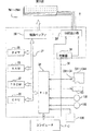
図1〜図3を参照して第1実施例に係る印刷記録材容器の識別装置の概略構成について説明する。図1は第1実施例に係る印刷記録材容器の識別装置が適用され得るカラープリンタの概略構成を示す説明図である。図2は第1実施例に係るカラープリンタの概略構成を示すブロック図である。図3はカラープリンタ10の制御回路30の内部構成を示す説明図である。
本実施例に係る印刷記録材容器(インクカートリッジ)の識別装置は、インクジェット式カラープリンタ(印刷装置)10上で実現されている。カラープリンタ10は、カラー画像の出力が可能なプリンタであり、例えば、シアン(C)、マゼンタ(M)、イエロー(Y)、ブラック(K)の4色の色インクを印刷媒体上に噴射してドットパターンを形成することによって画像を形成するインクジェット方式のプリンタである。色インクには、上記4色に加えて、ライトシアン(薄いシアン、LC)、ライトマゼンタ(薄いマゼンタ、LM)、ダークイエロ(暗いイエロ、DY)を用いても良い。なお、本実施例では、インクジェット式のカラープリンタを用いて説明するが、カラートナーを印刷媒体上に転写・定着させて画像を形成する電子写真方式のプリンタを用いても良い。
カラープリンタ10は、図1に示すように印刷機能部を内包する本体11、インクカートリッジCAを交換する際に開閉される破線にて示すカバー12を備えている。本体11の上面には、電源スイッチSW1、インクカートリッジ交換スイッチSW2、表示ランプLM等を備える操作パネル13、インクカートリッジ交換時にインクカートリッジCAを脱着するための交換用開口部14、メンテナンス用の開口部15が備えられている。また、本体11の前面には、図示しない給紙口から供給された後、印刷された用紙が排出される排紙口16が備えられている。なお、インク交換スイッチSW2は、各インクカートリッジCA毎に複数個設けられていても良いし、1つだけ設けられていても良い。
カラープリンタ10は、図2に示すように、キャリッジ101に搭載された印字ヘッド102を駆動してインクの吐出およびドット形成を行う機構と、このキャリッジ101をキャリッジモータ103によってプラテン104の軸方向に往復動させる機構と、紙送りモータ105によって印刷用紙Pを搬送する機構と、制御回路30とから構成されている。キャリッジ101をプラテン104の軸方向に往復動させる機構は、プラテン104の軸と並行に架設されたキャリッジ101を摺動可能に保持する摺動軸106と、キャリッジモータ103との間に無端の駆動ベルト107を張設するプーリ108と、キャリッジ101の原点位置を検出する位置検出センサ109等から構成されている。印刷用紙Pを搬送する機構は、プラテン104、プラテン104を回転させる紙送りモータ105、図示しない給紙補助ローラ、紙送りモータ105の回転をプラテン104および給紙補助ローラに伝えるギヤトレイン(図示省略)から構成されている。
制御回路30は、プリンタの操作パネル13と信号をやり取りしつつ、紙送りモータ105やキャリッジモータ103、印字ヘッド102の動きを適切に制御している。カラープリンタ10に供給された印刷用紙Pは、プラテン104と給紙補助ローラの間に挟み込まれるようにセットされ、プラテン104の回転角度に応じて所定量だけ送られる。制御回路30には、パーソナルコンピュータPCが接続されている。パーソナルコンピュータPCは、内部または外部に備えられた記憶装置(記録媒体)HDに格納されているプログラムに基づいて後述するインクカートリッジの識別処理を実行し、制御回路30に対して制御信号を送信する。本実施例では、制御回路30は、パーソナルコンピュータPCから受信した制御信号に従ってプリンタ10の各部の動作を制御する。
キャリッジ101にはインクカートリッジCA1〜CA5が装着される。インクカートリッジCA1には黒(K)インクが収容され、インクカートリッジCA2にはシアン(C)インク、インクカートリッジCA3にはマゼンタ(M)インク、インクカートリッジCA4にはイエロ(Y)インクが収容されている。なお、既述の通り、この他に、ライトシアン(LC)インク,ライトマゼンタ(LM)インク,ダークイエロ(DY)インクのインクカートリッジCAが装着されても良い。
制御回路30の内部構成について、図3を参照して説明する。制御回路30には、CPU31,PROM32,RAM33,インクカートリッジCA1〜CA4に備えられた記憶装置、紙送りモータ105やキャリッジモータ103等とデータのやり取りを行う周辺機器入出力部(PIO)34,タイマ35,駆動バッファ36等が設けられている。駆動バッファ36は、インク吐出用ヘッドPN1〜PN4にドットのオン・オフ信号を供給するバッファとして使用される。これらは互いにバス37で接続され、相互にデータにやり取りが可能となっている。また、制御回路30には、所定周波数で駆動波形を出力する発振器38、および発振器38からの出力をインク吐出用ヘッドPN1〜PN4に所定のタイミングで分配する分配出力器39も設けられている。
制御回路30は、インクカートリッジCAの交換時には、取り外されたインクカートリッジと新たに装着されたインクカートリッジCAとが同一のインク種を内包するインクカートリッジであるか否かを識別する。制御回路30は、紙送りモータ105やキャリッジモータ103の動きと同期を採りながら、所定のタイミングでドットデータを駆動バッファ37に出力する。制御回路30によって実行される詳細なインクカートリッジの識別処理の流れについては、以下に説明する。
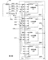
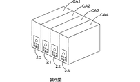
次に、図4および図5を参照してインクカートリッジに備えられている記憶装置とパーソナルコンピュータPCとの接続状態について説明する。図4はインクカートリッジに備えられている各記憶装置とパーソナルコンピュータPCとの接続状態を示すブロック図である。図5は記憶装置がインクカートリッジに適用される一例を示す説明図である。なお、図4では説明を容易にするために、記憶装置20,21,22,23とインクカートリッジCA1、CA2、CA3、CA4とが模式的に示されているに過ぎず、本実施例に係るインクカートリッジの識別装置は図4に示す構成に限定されるものではない。
各記憶装置20,21,22,23は、図5に示すようにインクジェットプリンタ用の4色のインクカートリッジCA1、CA2、CA3、CA4それぞれ備えられているものとする。4色のインクカートリッジCA1、CA2、CA3、CA4には、ブラック(K)インク、シアン(C)インク、マゼンタ(M)インク、イエロー(Y)インクがそれぞれ収容されている。また、本実施例では、記憶装置として不揮発的に記憶内容を保持すると共に記憶内容を書き換え可能なEEPROMを用いた。
各記憶装置20,21,22,23のデータ信号端子DT、クロック信号端子CT、リセット信号端子RTは、データバスDB、クロックバスCB、リセットバスRBを介してそれぞれ接続されている(図4および図7参照)。パーソナルコンピュータPCとデータバスDB、クロックバスCB、リセットバスRBとは、データ信号線DL、クロック信号線CL、リセット信号線RLを介して接続されている。なお、これら信号線は、例えば、フレキシブル・フィード・ケーブル(FFC)として実現され得る。パーソナルコンピュータPCの電源正極端子VDDHと各記憶装置20,21,22,23の電源正極端子VDDMとは電源供給線VDLを介して接続されている。また、各記憶装置20,21,22,23の電源負極端子VSSは、キャリッジ101上の接地線GDLに接続されている。キャリッジ101上には、インクカートリッジCA1〜CA4に備えられているカートリッジアウト検出用端子CAOTをカスケードに接続するカートリッジアウト検出線CDLが配置されている。カートリッジアウト検出線CDLの一端は接地されており、他端はカートリッジアウト信号線COLを介してパーソナルコンピュータPCのカートリッジアウト検出端子COTと接続されている。
本実施例では、各記憶装置20〜23の電源負極端子VSSに対して専用の接地線GDLが接続されるので、パーソナルコンピュータPCは、インクカートリッジCA1〜CA4が全て装着されていない場合にも、任意の記憶装置20〜23に対してアクセスすることができる。この構成は、特に、インクカートリッジCAの初期装着時、あるいは、複数のインクカートリッジCAを同時に交換する場合に有用である。
制御回路30は、CPU31を介して、クロック信号生成機能、リセット信号生成機能、電源監視機能、電源回路、電源補償回路、データ記憶回路および各回路を制御する制御機能を実現する制御装置であり、記憶装置20,21,22,23に対するアクセスを制御する。制御回路30は、カラープリンタ10の本体側に配置されており、電源がオンされると、記憶装置20,21,22,23からインク消費量、インクカートリッジの装着時間といったデータを取得しデータ記憶回路に記憶する。また、電源がオフされる際には、インク消費量、インクカートリッジの装着時間といったデータを記憶装置20,21,22,23に対して書き込む。
制御回路30は、インクジェットプリンタの電源投入時、インクカートリッジの交換時、印刷ジョブの終了時、インクジェットプリンタの電源遮断時等に、記憶装置20,21,22,23に対するアクセスを実行する。制御回路30は、記憶装置20,21,22,23へアクセスする場合には、リセット信号生成回路に対してリセット信号RSTの生成を要求する。したがって、停電時、電源プラグが抜かれた場合にもリセット信号RSTが生成される。CPU31は、電源補償回路を制御して、電源の供給が遮断された場合にも所定の期間(例えば、0.3s)電源を供給する。この結果、停電、電源プラグが抜かれることによってデータ書き込み中の電源が遮断されても、上記所定期間の間に書き込みを優先すべきデータの書き込みを完了することができる。電源補償回路としては、例えば、コンデンサが用いられる。
制御回路30は、電源回路を制御して正電源の出力を制御する。本実施例に係る制御回路30は、記憶装置20,21,22,23に対して、常時電源を供給しておらず、記憶装置20,21,22,23に対するアクセス要求が発生した場合にのみ、記憶装置20,21,22,23に対して正電源を供給する。
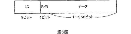
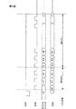
パーソナルコンピュータPCから送出されるデータ列について図6を参照して説明する。図6はパーソナルコンピュータPCから記憶装置20、21、22、23に対して送出されるデータ列の一例を示す説明図である。
パーソナルコンピュータPCから送出されるデータ列は、図7に示すように3ビットの識別データ部、1ビットの読み出し/書き込みコマンド部、1ビット〜252ビットの書き込み/読み出しデータ部を備える。パーソナルコンピュータPCは、記憶装置20,21,22,23からデータを読み出す場合には、制御回路30のクロック信号生成回路を制御して、例えば、4μS間隔のクロック信号SCKを生成し、データ書き込み時には3ms間隔のクロック信号SCKを生成させる。
B.第1実施例に係る記憶装置の構成
次に、図7を参照して記憶装置20,21,22,23の内部構成について説明する。図7は記憶装置20の内部回路構成を示すブロック図である。なお、個々の記憶装置20,21,22,23の内部構成は、格納されている識別情報(識別データ)、固有のデータを除いて同一であるから、以下の説明では代表的に記憶装置20の内部構成について説明する。
記憶装置20は、メモリアレイ201、アドレスカウンタ202、IDコンパレータ203、オペレーションコードデコーダ204、I/Oコントローラ205および工場設定ユニット206を備えている。
メモリアレイ201は、所定容量、例えば、256ビットの記憶領域を有し、先頭から3ビットの記憶領域には識別データが格納され、先頭から4ビット目の記憶領域は無効領域とされている。上述のように、CPU31から送出されるデータ列の先頭3ビットには識別データが格納され、先頭から4ビット目には書き込み/読み出しコマンドが格納されている。したがって、先頭から5ビット目以降の記憶領域でなければデータの書き込みは行われず、メモリアレイ201の記憶領域がこのような構成を備えることによって先頭4ビットは読み出し専用の記憶領域となる。メモリアレイ201は、書き込みが優先されるべき情報、たとえば、インク消費量またインク残量、を書き込む領域を先頭5ビット目から有している。
アドレスカウンタ202は、工場設定ユニット206を介して供給されるクロック信号SCKに同期してそのカウンタ値をインクリメントする回路であり、メモリアレイ201と接続されている。カウンタ値とメモリアレイ201の記憶領域位置(アドレス)とは関連付けられており、アドレスカウンタ202のカウンタ値によってメモリアレイ201における書き込み位置または読み出し位置を指定することができる。アドレスカウンタ202はまた、リセット信号端子RTと接続されており、リセット信号RSTが入力されると、カウンタ値を初期値にリセットする。ここで、初期値はメモリアレイ201の先頭位置と関連付けられていればどのような値でも良く、一般的には0が初期値として用いられる。
IDコンパレータ203は、クロック信号端子CT、データ信号端子DT、リセット信号端子RTと接続されており、データ信号端子DTを介して入力されたデータ列に含まれる識別データとメモリアレイ201に格納されている識別データとが一致するか否かを判定する。詳述すると、IDコンパレータ203は、リセット信号RSTが入力された後に入力される3ビット分のデータ、すなわち識別データを取得する。IDコンパレータ203は、データ列に含まれる識別データを格納する3ビットレジスタ(図示しない)、I/Oコントローラ205を介してメモリアレイ201から取得した識別データを格納する3ビットレジスタ(図示しない)を有しており、両レジスタの値が一致するか否かによって識別データが一致するか否かを判定する。IDコンパレータ203は、両識別データが一致する場合には、アクセス許可信号ENをオペレーションコードデコーダ204に送出する。IDコンパレータ203は、リセット信号RSTが入力されるとレジスタの値をクリアする。
オペレーションコードデコーダ204は、I/Oコントローラ205、クロック信号端子CT、データ信号端子DTと接続されており、リセット信号RSTが入力された後に入力される4ビット目のデータ、すなわち書き込み/読み出しコマンドを取得する。オペレーションコードデコーダ204は、アクセス許可信号ENが入力されると、取得した書き込み/読み出しコマンドを解析してI/Oコントローラ205に対して書き込み処理要求または読み出し処理要求を送出する。オペレーションコードデコーダ204はまた、工場設定ユニット206とも接続されており、テストモード時には書き込み/読み出しコマンドの解析が終了すると、解析終了通知を工場設定ユニット206に対して送出する。
I/Oコントローラ205は、データ信号端子DT、メモリアレイ201と接続されており、オペレーションコードデコーダ204からの要求に従ってメモリアレイ201に対するデータ転送方向ならびにデータ信号端子DTに対する(データ信号端子DTと接続されている信号線の)データ転送方向を切り換え制御する。I/Oコントローラ205は、リセット信号端子RTとも接続されており、リセット信号RSTを受信する。I/Oコントローラ205にはメモリアレイ201から読み出したデータおよびメモリアレイ201に対する書き込みデータを一時的に格納する第1のバッファメモリ(図示しない)と、データバスDBからのデータおよびデータバスDBへのデータを一時的に格納する第2のバッファメモリ(図示しない)を備えている。
I/Oコントローラ205は、リセット信号RSTの入力により初期化され、初期化時には、メモリアレイ201に対するデータ転送方向を読み出し方向に設定し、データ信号端子DTと接続されている信号線をハイインピーダンスとすることでデータ信号端子DTに対するデータ転送を禁止する。この初期化時の状態は、オペレーションコードデコーダ204から書き込み処理要求または読み出し処理要求が入力されるまで維持される。したがって、リセット信号入力後にデータ信号端子DTを介して入力されるデータ列の先頭4ビットのデータはメモリアレイ201に書き込まれることはなく、一方で、メモリアレイ201の先頭4ビット(内4ビット目は無効データ)に格納されているデータは、IDコンパレータ203に送出される。この結果、メモリアレイ201の先頭4ビットは読み出し専用状態となる。
工場設定ユニット206は、テスト信号端子TT、クロック信号端子CT、データ信号端子DTと接続されており、テスト信号が入力されるとテストモード処理を実行する。工場設定ユニット206は、テスト信号の入力がないときには受信したクロック信号SCKをそのままアドレスカウンタ202に転送し、テスト信号の入力があるときにはオペレーションコードデコーダ204から解析終了通知を受け取るまでアドレスカウンタ202に対するクロック信号SCKの転送を行わない。工場設定ユニット206は、オペレーションコードデコーダ204に対してテストモードコマンドを送出する。なお、テスト信号端子TTにはプルダウン抵抗が接続されており、通常時は非アクティブな端子とされている。
C.第1実施例に係るインクカートリッジの識別装置の動作
図8〜図14を参照して第1の実施例に係るインクカートリッジの識別装置の動作について説明する。図8は、パーソナルコンピュータPCが制御回路30を介して、インクカートリッジCA1〜CA4の記憶装置20,21,22,23に対してアクセスする際に実行する一般的な処理ルーチンを示すフローチャートである。図9は、データ読み出し時におけるリセット信号RST、クロック信号SCK、データ信号CDAおよびアドレスカウンタ値の時間的関係を示すタイミングチャートである。図10は、データ書き込み時におけるリセット信号RST、クロック信号SCK、データ信号CDAおよびアドレスカウンタ値の時間的関係を示すタイミングチャートである。図11は、インクカートリッジの初期装着時に実行されるインクカートリッジ識別処理の処理ルーチンを示すフローチャートである。図12〜図14は、インクカートリッジ交換時におけるインクカートリッジCA1〜CA4の移動の様子を示す説明図である。
パーソナルコンピュータPCは、カートリッジアウト信号線COLの入力値COが0となるまで待機する(ステップS100:No)。すなわち、全てのインクカートリッジが正しくインクカートリッジホルダに収容されている場合には、各カートリッジアウト検出用端子COTを介してカートリッジアウト検出線CDLがカスケードに接続されて接地されるのでカートリッジアウト信号線COLの入力値COは接地電圧(例えば、約0ボルト)を示すからである。これに対して、たとえ、1個のインクカートリッジでもインクカートリッジホルダに正しく収容されていない場合には、カートリッジアウト検出線CDLはカスケードに接続されないので、接地されず、制御回路の回路電圧に対応する値がカートリッジアウト信号線COL上に現れる。但し、本実施例ではノイズ等の影響を排除するため、所定のしきい値を基準にして2値化している。したがって、カートリッジアウト信号線COLの入力値COは0か1を取る。
パーソナルコンピュータPCは、カートリッジアウト信号線COLの入力値COが0を取ると(ステップS100:Yes)、図9および図10に示すように電源供給線VDLを介して電源電圧を記憶装置20,21,22,23の電源正極端子VDDMに供給し(VDD=1)、リセット信号生成回路にリセット・ロー信号を生成させて(RST=0にセット)リセット信号線RLを介してリセットバスRBに送出する(ステップS110)。すなわち、インクカートリッジがインクカートリッジホルダに正しく収容されない限り、記憶装置20,21,22,23に対しては電源電圧が供給されない。なお、リセット信号RSTはアクティブ・ローであるものとし、本明細書中にて用いられるリセット信号RSTが生成される、入力されるといった用語は、特に断らない限りリセット・ロー信号を意味するものとする。
パーソナルコンピュータPCは、続いて図9および図10に示すようにリセット信号生成回路にRST=1とさせてリセット信号RSTをハイに設定する(ステップS120)。パーソナルコンピュータPCは、アクセスを所望するインクカートリッジ(記憶装置20,21,22,23)の識別データ(IDデータ)を発行する(ステップS130)。発行されたIDデータは、図9および図10に示すようにクロック信号SCKの立ち上がりエッジに同期されてデータ信号線DLを介してデータバスDBに転送される。
パーソナルコンピュータPCは、読み出しコマンド(Read)または、書き込みコマンド(Write)のいずれかを発行する(ステップS140)。発行されたコマンドは、データ信号線DLを介してデータバスDBに転送される。CPU31は、発行したコマンドが書き込みコマンドの場合にはクロック信号速度を遅らせ、発行したコマンドが読み出しコマンドの場合にはクロック信号速度を維持する。
パーソナルコンピュータPCは、書き込みまたは読み出しを所望するメモリアレイ201のアドレス(位置)に対応する数のクロック信号パルスを発行する(ステップS150)。すなわち、本実施例における記憶装置20はシーケンシャルアクセスタイプの記憶装置であるから、書き込みまたは読み出しを所望するアドレスに対応する数のクロック信号パルスを発行し、アドレスカウンタ202のカウンタ値を所定のアドレスに対応するカウント値までインクリメントしなければならない。パーソナルコンピュータPCは、最後に、リセット信号生成回路にリセット・ロー信号を生成させて(RST=0にセット)リセット信号線RLを介してリセットバスRBに送出して記憶装置20,21,22,23に対するアクセスを完了する。このように、リセット信号RST(リセット・ロー信号)の送出によりアクセスを完了し、また、電源遮断時にもリセット信号RSTを送出するので、データ書き込み中に電源が遮断された場合でも少なくとも書き込みを終えたデータの書き込み処理を正常に完了することができる。
次に、図11〜図14を参照してインクカートリッジの初期装着時に実行されるインクカートリッジ識別処理について説明する。電源がオンされると、パーソナルコンピュータPCはインク交換要求を受ける(ステップS200)。インク交換要求は、インクカートリッジCA1〜CA4が装着されていない状態で電源がオンされた場合に自動的に、あるいは、パーソナルコンピュータPCに接続されている表示ディスプレイ上に表示されるドライバアプリケーションのユーザーインターフェースを介してインクカートリッジCAの初期装填が指示された場合に発生する。また、操作パネル13上のインクカートリッジ交換スイッチSW2が操作された場合にも発生する。
パーソナルコンピュータPCは、制御回路30を介して第n番目のインクカートリッジを交換位置まで移動させる(ステップS210)。なお、パーソナルコンピュータPCはnの初期値として「1」を用いるものとし、以下の説明ではn=1として説明する。したがって、図12に示すように、先ず、第1番目のインクカートリッジCA1が、交換用開口部14に対応する位置まで移動させられる。ここで、交換用開口部14が形成されている位置と各インクカートリッジCAとの移動距離は、ホームポジションからのキャリッジ101の移動距離としてそれぞれ設定されている。したがって、インクカートリッジCAを所定の位置まで移動させる際には、各インクカートリッジCAに応じて設定されている距離だけキャリッジ101を移動させればよい。なお、キャリッジ101の移動距離はリニアエンコーダ等を利用して正確に計測(検出)することができる。また、インクカートリッジCA2、CA3、CA4についても図13および図14に示すように、順次、交換用開口部14に対応する位置まで移動させられる。なお、説明を簡略にするため、インクカートリッジCA2、CA3の場合についてのみ図示した。
パーソナルコンピュータPCは、既述のようにカートリッジアウト信号COOに基づいてインクカートリッジCA1が装着されるまで待機し(ステップS220:No)、インクカートリッジCA1が装着されると(ステップS220:Yes)、インクカートリッジCA1の記憶装置20が保有する識別データに対応する識別データをデータバスDB上に送信する(ステップS230)。
パーソナルコンピュータPCは送信した識別データに対して応答があるか否かを判定する(ステップS240)。すなわち、装着されるべきインクカートリッジCA1が装着されている場合には、送信された識別データに対応する識別データを保有する記憶装置20が応答し、誤ったインクカートリッジCAが装着されている場合には、いずれの記憶装置も記憶装置20に対応する識別データに対して応答することができない。パーソナルコンピュータPCは、応答がない場合には(ステップS240:No)、誤ったインクカートリッジCAが装着されている旨を報知し(ステップS250)、ステップS220に戻り、再度、正しいインクカートリッジCAの装着を検出する。誤ったインクカートリッジCAの装着の報知は、例えば、操作パネル13上配置されているランプLMを点滅させても良い。あるいは、制御回路30を介して接続されているパーソナルコンピュータのディスプレイ上に表示されるドライバアプリケーションユーザインタフェース画面を介して警告を表示するようにしてもよい。
パーソナルコンピュータPCは、応答がある場合には(ステップS240:Yes)、全てのインクカートリッジCA1〜CA4の装着が終了したか否か、すなわち、n=mであるか否かを判定する(ステップS260)。既述の説明から理解されるように、本実施例ではm=4である。パーソナルコンピュータPCは、n=mでないと判定した場合には(ステップS260:No)、nをインクリメント(n=n+1)する(ステップS270)。すなわち、次のインクカートリッジCA2〜CA4の装着が正しく行われるか否かを識別(監視)する。なお、インクカートリッジCA2〜CA4は、図13および図14に示すように順次、交換用開口部14に対応する位置まで移動させられる。
パーソナルコンピュータPCは、n=mであると判定した場合には(ステップS260:Yes)、全てのインクカートリッジCA1〜CA4の装着が正しく終えられたものと判定し、本処理ルーチンを終了する。
以上説明したように、第1実施例に係るインクカートリッジの識別装置によれば、インクカートリッジCAの初期装着時において、各インクカートリッジCA1〜CA4が備える記憶装置20〜23に格納されている識別データを利用して、正しいインクカートリッジCAが装着されたか否かを検出することができる。また、検出した結果を利用して、誤ったインクカートリッジCAが装着された旨を報知することが可能となり、正しいインクカートリッジCAの装着を促すことができる。さらに、誤ったインクカートリッジCAが装着された場合には、正しいインクカートリッジCAが装着されるまでインクカートリッジCAの識別処理は継続されるので、インク吐出用ヘッドPN1〜PN4とインクカートリッジCA1〜CA4の対応関係を適切に維持することができる。
本実施例では、インクカートリッジの外形に特徴を持たせることなくインクカートリッジCAの誤装着を検出することができるので、同一形状のインクカートリッジCAを用いることが可能となり、収容されるインク種毎に異なる外形を変更する場合に必要なコストを削減することができる。また、本実施例に係るインクカートリッジの識別装置は、交換用開口部14を備えてインクカートリッジCAの装着位置を制限することができるので、正しいインクカートリッジCAを正しい位置に装着させることができる。
D.第2実施例に係るインクカートリッジの識別処理
次に、図15を参照して第2実施例に係るインクカートリッジの識別処理について説明する。図15は第2実施例に係るインクカートリッジの識別処理に際して実行される処理ルーチンを示すフローチャートである。なお、第2実施例に係るインクカートリッジの識別処理は、第1実施例に係るインクカートリッジの識別装置上で実行され得る。
本処理ルーチンは、インクカートリッジCA1〜CA4の初期装着終了後、インクカートリッジCAが空になったとき等に実行される。したがって、パーソナルコンピュータPCは、インク交換要求が発生するまで待機する(ステップS300:No)。インク交換要求は、例えば、カラープリンタ10の制御回路30が各インクカートリッジCA1〜CA4のインク残量を監視し、各インクカートリッジCA1〜CA4のインク残量が所定値以下となった場合に発行する(発生させられる)。あるいは、パーソナルコンピュータPCに接続されている表示ディスプレイ上に表示されるドライバアプリケーションのユーザーインターフェースを介して、ユーザが恣意的に所望のインクカートリッジの交換を指示した場合に発生する。また、ユーザがインクカートリッジ交換スイッチSW2を操作することによっても発生する。
パーソナルコンピュータPCは、インク交換要求が発生したと判定した場合には(ステップS300:Yes)、交換を要求されたインクカートリッジCAを特定する(ステップS310)。インク交換要求が制御回路30により発生された場合には、パーソナルコンピュータPCにとって交換の対象となるインクカートリッジCAは既知(特定済み)である。インク交換要求がドライバアプリケーションのユーザーインターフェースを介してユーザによって恣意的に発生された場合には、ユーザーインターフェースを介して入力された指定情報を取得することによって特定する。なお、以下の説明では、説明の便宜上、インクカートリッジCA1の交換要求が発生したものとする。
パーソナルコンピュータPCは、交換の要求されたインクカートリッジCA1を交換用開口部14まで移動させて(ステップS320)、新たなインクカートリッジCA1の装着を待機する(ステップS330:No)。すなわち、CO=1を検出した後にCO=0を検出するまで待機する。パーソナルコンピュータPCは、CO=0を検出すると(ステップS330:Yes)、先に特定したインクカートリッジCA1に対応する識別データをデータバスDB上に送信する(ステップS340)。
パーソナルコンピュータPCは、インクカートリッジCA1に備えられている記憶装置20からの応答を検出した場合には(ステップS350:Yes)、新たなインクカートリッジCA1が正しく装着されたものと判断し、本処理ルーチンを終了する。一方、パーソナルコンピュータPCは、インクカートリッジCA1に備えられている記憶装置20からの応答を検出しなかった場合には(ステップS350:No)、新たなインクカートリッジCA1が正しく装着されなかったものと判断し、誤ったインクカートリッジCAが装着された旨を報知し(ステップS360)、正しいインクカートリッジCA1の装着を再度、試みる(ステップS340〜ステップS360)。なお、誤ったインクカートリッジCAの報知は、第1実施例において説明した形態に準じて実行される。
以上説明したように、第2実施例に係るインクカートリッジの識別装置によれば、インクカートリッジCAの交換時において、各インクカートリッジCA1〜CA4が備える記憶装置20〜23に格納されている識別データを利用して、正しいインクカートリッジCAが装着されたか否かを検出することができる。また、検出した結果を利用して、誤ったインクカートリッジCAが装着された旨を報知することが可能となり、正しいインクカートリッジCAの装着を促すことができる。さらに、誤ったインクカートリッジCAが装着された場合には、正しいインクカートリッジCAが装着されるまでインクカートリッジCAの識別処理は継続され、インクカートリッジCA内のインクの吸引処理は実行されないので、誤ったインクを吸引することに起因するインク吐出用ヘッドPN1〜PN4の汚染を防止することができる。
本実施例では、インクカートリッジの外形に特徴を持たせることなくインクカートリッジCAの誤装着を検出することができるので、同一形状のインクカートリッジCAを用いることが可能となり、収容されるインク種毎に外形を変更する必要がなくなり、外形の変更に伴うコストを削減することができる。また、本実施例に係るインクカートリッジの識別装置は、交換用開口部14を備えて取り外されるインクカートリッジCAを制限すると共に、インクカートリッジCAの装着位置を制限することができるので、交換されるべきインクカートリッジCAを正しく脱着させることができる。
E.第3実施例に係るインクカートリッジの識別処理
次に、図16および図17を参照して第3実施例に係るインクカートリッジの識別処理について説明する。図16は第3実施例に係るインクカートリッジの識別処理に際して実行される処理ルーチンを示すフローチャートである。図17は図16中のインクカートリッジ特定処理において実行される処理ルーチンを示すフローチャートである。ここで、第3実施例に係るインクカートリッジの識別処理は、交換用開口部14を備えず、ユーザが任意のインクカートリッジCAを脱着可能なプリンタに適している。なお、第3実施例に係るインクカートリッジの識別処理は、交換用開口部14および交換対象となるインクカートリッジCAの移動を必要としないものの、第1実施例に係るインクカートリッジの識別装置に対して適用可能であるから、以下の説明では第1実施例に係るインクカートリッジの識別装置において用いた符号と同一の符合を用いるものとする。ただし、交換対象となるインクカートリッジCAの移動は実行されず、インクカートリッジCAは任意に脱着可能であることを前提とする。
第3実施例に係るインクカートリッジの識別処理は、インクカートリッジCA1〜CA4の初期装着終了後、インクカートリッジCAが空になったとき等に実行される。したがって、パーソナルコンピュータPCは、インク交換要求が発生するまで待機する(ステップS400:No)。インク交換要求は、例えば、各インクカートリッジCA1〜CA4のインク残量を監視する制御回路30によって、各インクカートリッジCA1〜CA4のインク残量が所定値以下となった場合、あるいは、パーソナルコンピュータPCに接続されている表示ディスプレイ上に表示されるドライバアプリケーションのユーザーインターフェースを介して、ユーザが恣意的に所望のインクカートリッジCAの交換を指示した場合に発生する。あるいは、カラープリンタ10に備えられているインクカートリッジ交換スイッチSW2を操作することにより発生する。
パーソナルコンピュータPCは、インク交換要求が発生したと判定した場合には(ステップS400:Yes)、インクカートリッジ特定処理を実行する(ステップS410)。本実施例では、ユーザによって任意のインクカートリッジCAが脱着され得るので、取り外されたインクカートリッジCAが、交換を要求されたインクカートリッジCAと同一であるか否かを特定するためのインクカートリッジ特定処理が必要となる。このインクカートリッジ特定処理について図17を参照して詳細に説明する。
パーソナルコンピュータPCは、先ず、交換を要求されたインクカートリッジCAを特定する(ステップS4100)。インク交換要求が制御回路30により発生された場合、パーソナルコンピュータPCは交換の対象となるインクカートリッジCAを特定済みである。また、インク交換要求がユーザによって恣意的に発生された場合には、パーソナルコンピュータPCは、ユーザインターフェース上においてユーザにより指定されるインクカートリッジCAの指定情報を取得することによって交換されるべきインクカートリッジCAを特定する。なお、以下の説明では、説明の便宜上、インクカートリッジCA1の交換要求が発生したものとする。
パーソナルコンピュータPCは、カートリッジアウト信号COOの入力値COが1となるまで、すなわち、インクカートリッジCAが取り外されるまで待機する(ステップS4110:No)。かかる場合、パーソナルコンピュータPCは、どのインクカートリッジCAが取り外されたかまでは特定することはできず、いずれかのインクカートリッジCAの取り外しを待機することとなる。パーソナルコンピュータPCは、カートリッジアウト信号COOの入力値CO=1を検出すると(ステップS4110:Yes)、先に特定したインクカートリッジCA1に対応する識別データをデータバスDB上に送出する(ステップS4120)。
パーソナルコンピュータPCは、データバスDB上に送出した識別データに対して応答があるか否かを判定する(ステップS4130)。既述のように各インクカートリッジCA1〜CA4の記憶装置20〜23は、自己の保有する識別データと一致する識別データを受信しない限り応答しないので、識別データをデータバスDB上に送出することによって交換を要求されたインクカートリッジCA1が正しく取り外されたか否かを検出することができる。パーソナルコンピュータPCは、インクカートリッジCA1に備えられている記憶装置20からの応答を検出しない場合には(ステップS4130:No)、交換を要求されたインクカートリッジCA1が正しく取り外されたものと判定し、図16の処理ルーチンにリターンする。すなわち、以上の処理により、交換要求されたインクカートリッジCA1と取り外されたインクカートリッジCAとが同種のインクカートリッジCAであることが識別される。そして、次に、図15に示す処理ルーチンにて、装着されたインクカートリッジCAがインクカートリッジCA1と同種のインクカートリッジCAであるか否かを判定する。
一方、パーソナルコンピュータPCは、インクカートリッジCA1に備えられている記憶装置20からの応答を検出した場合には(ステップS4130:Yes)、全ての記憶装置20〜23が保有する識別データに対応する識別データを順次、データバスDB上に送出する(ステップS4140)。かかる場合には、交換を要求されたインクカートリッジCA1以外のインクカートリッジCAが取り外されており、いずれのインクカートリッジCAが取り外されたかを特定する必要があるからである。
パーソナルコンピュータPCは、データバスDB上に順次、送出した識別データのうち、応答のなかった識別データに対応する記憶装置を備えるインクカートリッジCAを特定すると共に、実際に取り外されたインクカートリッジCAの情報として図示しないRAM上に一時的に格納する(ステップS4150)。パーソナルコンピュータPCは、誤ったインクカートリッジCAが取り外された旨を報知し(ステップS4160)、図16に示す処理ルーチンにリターンする。以上の処理によって、交換要求のあったインクカートリッジCA1に代わって実際に取り外されたインクカートリッジCAを特定(識別)することができる。このインクカートリッジ特定処理を実行することによって、取り外されたインクカートリッジCAと装着されたインクカートリッジCAとが同一種のインクカートリッジCAであるか否かを判定することができる。交換要求のあったインクカートリッジCA以外のインクカートリッジCAが取り外される可能性がある場合には、上述のインクカートリッジ特定処理を実行しなければ、交換要求のあったインクカートリッジCAと取り外されたインクカートリッジCAとが同一種であるか否かを確定することができないからである。
図16に戻り説明を続けると、パーソナルコンピュータPCは、新たなインクカートリッジCAの装着を検出するまで、すなわち、CO=0を検出するまで待機する(ステップS420:No)。パーソナルコンピュータPCは、CO=0を検出すると(ステップS420:Yes)、インクカートリッジ特定処理において特定したインクカートリッジCAに対応する識別データをデータバスDB上に送信する(ステップS430)。
パーソナルコンピュータPCは、特定したインクカートリッジCA(あるいは、インクカートリッジCA1)に備えられている記憶装置(あるいは、記憶装置20)からの応答を検出した場合には(ステップS440:Yes)、新たなインクカートリッジCAが正しく装着されたものと判断し、本処理ルーチンを終了する。一方、パーソナルコンピュータPCは、特定したインクカートリッジCAに備えられている記憶装置からの応答を検出しなかった場合には(ステップS440:No)、先に取り外されたインクカートリッジCAと同種のインクカートリッジCAが装着されなかったものと判断し、誤ったインクカートリッジCAが装着された旨を報知し(ステップS450)、正しいインクカートリッジCAの装着を再度、試みる(ステップS410〜ステップS440)。なお、誤ったインクカートリッジCAの報知は、第1実施例において説明した形態に準じて実行される。
以上説明したように、第3実施例に係るインクカートリッジの識別装置によれば、インクカートリッジCAの交換時において、各インクカートリッジCA1〜CA4が備える記憶装置20〜23に格納されている識別データを利用して、正しいインクカートリッジCAが装着されたか否かを検出することができる。また、本実施例では、取り外されたインクカートリッジCAが取り外されるべきインクカートリッジCAであるか否かを識別することができるので、プリンタが、例えば、交換用開口部14を設け、交換対象のインクカートリッジCAを交換用開口部14まで移動させるといった、物理的な制限構造を備えない場合にも、取り外されたインクカートリッジCAと装着されたインクカートリッジCAとが一致するか否かを正確に識別することができる。なお、交換用開口部14等の物理的な制限構造を備えるプリンタに対して、第3実施例に係るインクカートリッジの識別処理を適用できることはもちろんである。かかる場合には、通常の手順を経ることなくインクカートリッジCAが取り外された場合であっても、より確実に、取り外されたインクカートリッジCAと装着されたインクカートリッジCAとが同一のインク種のものであるか否かを識別することができる。
また、検出した結果を利用して、誤ったインクカートリッジCAが装着された旨を報知することが可能となり、正しいインクカートリッジCAの装着をパーソナルコンピュータPCの表示画面上のユーザーインターフェースあるいは、カラープリンタ10上の表示ランプLMを介して促すことができる。さらに、誤ったインクカートリッジCAが装着された場合には、正しいインクカートリッジCAが装着されるまでインクカートリッジCAの識別処理は継続され、インクカートリッジCA内のインクの吸引処理は実行されないので、誤ったインクを吸引することに起因するインク吐出用ヘッドPN1〜PN4の汚染を防止することができる。
本実施例では、インクカートリッジの外形に特徴を持たせることなくインクカートリッジCAの誤装着を検出することができるので、同一形状のインクカートリッジCAを用いることが可能となり、収容されるインク種毎に異なる外形を変更する場合に必要なコストを削減することができる。
F.第4実施例に係るインクカートリッジの識別装置
図18を参照して第4実施例に係るインクカートリッジの識別装置について説明する。図18は第4実施例に係るインクカートリッジの識別装置に用いられる記憶装置と制御回路との接続状態を示すブロック図である。なお、第4実施例に係るインクカートリッジの識別装置は、記憶装置と制御回路との接続状態が一部異なる点を除いて、基本的に第1実施例に係るインクカートリッジの識別装置と同一の構成を備えるので、同一の構成要素については同一の符合を付してその説明を省略する。
本実施例における各記憶装置40,41,42,43のデータ信号端子DT、クロック信号端子CT、リセット信号端子RTは、データバスDB、クロックバスCB、リセットバスRBを介してそれぞれ接続されている。パーソナルコンピュータPCとデータバスDB、クロックバスCB、リセットバスRBとは、データ信号線DL、クロック信号線CL、リセット信号線RLを介して接続されている。なお、これら信号線は、例えば、フレキシブル・フィード・ケーブル(FFC)として実現され得る。CPU31の電源正極端子VDDHと各記憶装置40,41,42,43の電源正極端子VDDMとは電源供給線VDLを介して接続されている。また、各記憶装置40,41,42,43の電源負極端子VSSは、キャリッジ101上に備えられている電源負極信号線VSLを介してカスケードに接続される。電源負極信号線VSLの一端は接地されており、他端はカートリッジアウト信号線COLを介してパーソナルコンピュータPCのカートリッジアウト検出端子COTと接続されている。
第4実施例に係るインクカートリッジの識別装置では、電源負極信号線VSLをカートリッジアウト検出線として共用されているので、各記憶装置40〜43に対する信号線の配置を容易にすることができる。また、インクカートリッジの初期装着時を除けば、他に特別な手段を講じることなく、正しいインクカートリッジCAが装着されたか否かを正確に識別することができる。
G.第5実施例に係るインクカートリッジの識別交換処理
次に、図19を参照して第5実施例に係るインクカートリッジの識別交換処理について説明する。図19は第5実施例に係るインクカートリッジの識別交換処理に際して実行される処理ルーチンを示すフローチャートである。なお、第5実施例に係るインクカートリッジの識別交換処理は、第1実施例に係るインクカートリッジの識別装置上で実行され得る。
本処理ルーチンは、インクカートリッジCA1〜CA4の初期装着終了後、インクカートリッジCAに含まれるインクが空になったとき等に実行される。したがって、パーソナルコンピュータPCは、インク交換要求が発生するまで待機する(ステップS500:No)。インク交換要求は、例えば、カラープリンタ10の制御回路30が各インクカートリッジCA1〜CA4のインク残量を監視し、各インクカートリッジCA1〜CA4のインク残量が所定値以下となった場合に発行する(発生させられる)。あるいは、パーソナルコンピュータPCに接続されている表示ディスプレイ上に表示されるドライバアプリケーションのユーザーインターフェースを介して、ユーザが恣意的に所望のインクカートリッジの交換を指示した場合に発生する。また、ユーザがインクカートリッジ交換スイッチSW2を操作することによっても発生する。
パーソナルコンピュータPCは、インク交換要求が発生したと判定した場合には(ステップS500:Yes)、交換を要求されたインクカートリッジCAを特定する(ステップS510)。インク交換要求が制御回路30により発生された場合には、パーソナルコンピュータPCにとって交換の対象となるインクカートリッジCAは既知(特定済み)である。インク交換要求がドライバアプリケーションのユーザーインターフェースを介してユーザによって恣意的に発生された場合には、ユーザーインターフェースを介して入力された指定情報を取得することによって特定する。なお、以下の説明では、説明の便宜上、インクカートリッジCA1の交換要求が発生したものとする。
パーソナルコンピュータPCは、交換の要求されたインクカートリッジCA1を交換用開口部14まで移動させて(ステップS520)、新たなインクカートリッジCA1の装着を待機する(ステップS530:No)。すなわち、CO=1を検出した後にCO=0を検出するまで待機する。パーソナルコンピュータPCは、CO=0を検出すると(ステップS530:Yes)、先に特定したインクカートリッジCA1に対応する識別データ(識別符号)をデータバスDB上に送信する(ステップS540)。
パーソナルコンピュータPCは、インクカートリッジCA1に備えられている記憶装置20からの応答を検出した場合には(ステップS550:Yes)、新たなインクカートリッジCA1が正しく装着されたものと判断し、本処理ルーチンを終了する。一方、パーソナルコンピュータPCは、インクカートリッジCA1に備えられている記憶装置20からの応答を検出しなかった場合には(ステップS550:No)、インクカートリッジCA1との交換が許容されるインクカートリッジCA*が存在するか否か、すなわち、インクカートリッジCA1に対応する識別データに代えて使用が許容される識別符号が存在するか否かを判断する(ステップS560)。
この判断は、例えば、ブラックインクを収容するインクカートリッジCA1に代えてダークイエローを収容するインクカートリッジCA*を装着する場合、マゼンタ、シアンに代えて、ライトマゼンタ、ライトシアンをそれぞれ装着するインク種の変更を許容するために必要な判断である。許容される識別符号は、パーソナルコンピュータPC内のROM(図示しない)またはプリンタ10内のPROM32に格納されている。
パーソナルコンピュータPCは、許容される識別符号が存在すると判定した場合には(ステップS560:Yes)、許容される識別符号をデータバスDB上に送信する(ステップS565)。パーソナルコンピュータPCは、インクカートリッジCA1に代えて装着されたインクカートリッジCA*に備えられている記憶装置からの応答を検出した場合には(ステップS570:Yes)、新たなインクカートリッジCA*が正しく装着されたものと判断する。
パーソナルコンピュータPCは、プリンタ10の制御回路30を介してインク吐出用ヘッドPN1のクリーニング処理を実行して(ステップS580)、本処理ルーチンを終了する。インクカートリッジCA1とインクカートリッジCA*とでは、内包するインク種(インク色)が異なるので、インク吐出用ヘッドPN1に残存しているインクカートリッジCA1のインク滴を除去(クリーニング)して、インクカートリッジCA1のインクとインクカートリッジCA*のインクとの混合を防止するのである。クリーニングは、例えば、新たなインクカートリッジCA*からのインクの吸引に先立って一般的に実行されているインク滴の強制吐出を実行し、その後、新たなインクカートリッジCA*のインクを吸引して再度、強制吐出を実行することによってインク吐出用ヘッドPN1内のインク滴を新たなインクカートリッジCA*のインクに置き換えることにより実行される。
一方、パーソナルコンピュータPCは、インクカートリッジCA*に備えられている記憶装置からの応答を検出しなかった場合には(ステップS570:No)、再度、インクカートリッジCA1との交換が許容される他のインクカートリッジCA*が存在するか否かを判断する(ステップS560)。すなわち、インクカートリッジCA1との交換が許容されるインクカートリッジCA*が複数存在する場合に対応して、候補となるインクカートリッジCA*の識別符号が順次用いられる。
パーソナルコンピュータPCは、許容される識別符号が存在すると判定した場合には(ステップS560:Yes)、既述のステップS565〜ステップS580の処理を実行する。一方、パーソナルコンピュータPCは、許容される識別符号が存在しないと判定した場合には(ステップS560:No)、新たなインクカートリッジCA1またはインクカートリッジCA*が正しく装着されなかったものと判断し、誤ったインクカートリッジCAが装着された旨を報知し(ステップS590)、正しいインクカートリッジCA1、CA*の装着が完了するまで待機する(ステップS340〜ステップS360)。なお、誤ったインクカートリッジCAの報知は、第1実施例において説明した形態に準じて実行される。
以上説明したように、第5実施例に係るインクカートリッジの識別装置によれば、あるインクカートリッジCAに対して交換が許容されるインクカートリッジCA*が存在する場合にも、正しいインクカートリッジCAが装着されたか否かを検出することができる。また、インクカートリッジCAが交換前のインク種(インク色)を含むインクカートリッジCAと交換された場合には、インク吐出ヘッドPNのクリーニング処理を実行するので、交換前のインクと交換後のインクとの混合を防止することができる。したがって、インク色が交換された場合であっても、正しいインクが吐出され、正しい画像出力を得ることができる。
さらに、インクカートリッジCAの交換が許容されるので、例えば、文書を印刷する際にはブラックインクのインクカートリッジCA1を複数用い、画像を印刷する場合には画像印刷用のライトインクを用いることによって、印刷目的に適切なインクカートリッジ構成にて印刷を実行することができる。
第5の実施例によれば、この他にも、第2の本実施例により得られる種々の効果を同様にして得ることができる。
H.その他の実施例
上記実施例では、カラープリンタ10に一個のインクカートリッジCAのみの脱着を許容するインクカートリッジ交換用の交換用開口部14を設け、交換されるべきインクカートリッジCAを示し、交換されるべきインクカートリッジCAが正しく取り外される構成を備えている。これに対して、交換用開口部14を設けることなく、複数のインクカートリッジCAの脱着を許容する一般的な開口部を用い、図20および図21に示すようにして、交換されるべきインクカートリッジCAを示しても良い。図20は交換対象となるインクカートリッジCAを示す矢印Yが付されたカラープリンタ10のメンテナンス用開口部15を示す説明図である。図21は交換対象となるインクカートリッジCAを示すLEDを備えるキャリッジ101’を示す説明図である。
図20に示す実施例では、制御回路30は、キャリッジモータ103を駆動して、交換対象となるインクカートリッジCAをメンテナンス用開口部15に設けられた矢印Yの位置まで移動させることによって交換対象となるインクカートリッジCAをユーザに示す。したがって、プリンタ10に交換用開口部14を特別に設けることなくして、ユーザに対して交換されるべきインクカートリッジCAを矢印Yによって指し示し、正しいインクカートリッジCAの交換を実現することができる。なお、複数個のインクカートリッジCAが交換対象となっている場合には、複数回にわたって交換対象となるインクカートリッジを矢印Yの位置まで移動させる処理が繰り返し実行される。また、インク交換位置19に矢印Yを設け、インク交換位置にて交換対象となるインクカートリッジを指し示しても良い。かかる場合には、交換すべきインクカートリッジをより認識しやすいという利点がある。
図21に示す実施例では、搭載されているインクカートリッジCAに対応する数だけキャリッジ101上にLED18が備えられている。インクカートリッジCAの交換時には、制御回路30は、キャリッジ101をインク交換位置19まで移動させた後、交換の対象となるインクカートリッジCAに対応するLED18を点灯または点滅させて、交換対象となるインクカートリッジCAをユーザに指し示す。交換対象となるインクカートリッジCAが複数個存在する場合には、複数のLED18が同時に点灯される。なお、インク交換位置19は、複数のインクカートリッジCAの脱着を許容する一般的な開口部である。したがって、インクカートリッジCAの交換にあたって、キャリッジ101を複数回移動させることなく交換対象となるインクカートリッジCAを特定(指し示す)ことができると共に、ユーザは交換対象となるインクカートリッジCAを記憶する必要なく、正しいインクカートリッジCAを更に容易に交換することができる。なお、LED18は、キャリッジ101上ではなく、インク交換位置19の開口部に備えられていても良い。また、LEDに限らず白熱灯を始めとする種々のライトが用いられることはいうまでもない。
以上、いくつかの実施例に基づき本発明に係る印刷記録材容器(インクカートリッジ)の識別装置を説明してきたが、上記した発明の実施の形態は、本発明の理解を容易にするためのものであり、本発明を限定するものではない。本発明は、その趣旨並びに特許請求の範囲を逸脱することなく、変更、改良され得ると共に、本発明にはその等価物が含まれることはもちろんである。
上記実施例では、チップセレクト信号を用いることなく、各インクカートリッジCAが備える記憶装置20〜23、40〜43が格納する識別データのみを用いて所望のインクカートリッジCAを識別するインクカートリッジの識別装置を用いて説明したが、本発明は、チップセレクト信号を用いてインクカートリッジCAを選択する場合にも適用される。かかる場合には、各記憶装置を識別するために、制御回路と各記憶装置との間には更にチップセレクト信号線が配線される。制御回路はチップセレクト信号によってアクセスを所望する記憶装置を特定することが可能であり、アクセスに先立って所望の記憶装置に対してチップセレクト信号を送信する。チップセレクト信号線と各インクカートリッジCAの装着位置とは関連付けられているので、制御回路はインクカートリッジ(記憶装置)の位置情報を予め保有していることとなり、この位置情報を利用することによって一度に複数のインクカートリッジが脱着された場合にも個々のインクカートリッジの装着位置に正しいインクカートリッジが装着されたか否かを特定することができる。ただし、この場合であっても、インクカートリッジがいずれのインク種を内包するか否かは各記憶装置に格納されている識別データが用いられることはいうまでもない。
上記実施例では、パーソナルコンピュータPCによってインクカートリッジCAの識別処理が実行されているが、これら一連の処理をカラープリンタ20の制御回路30によって実行してもよい。かかる場合には、インクカートリッジCAの識別処理をカラープリンタ20単独で実行することができる。カラープリンタ20のみによってインクカートリッジCAの識別処理が実行される場合には、誤ったインクカートリッジCAの装着時等になされる報知は、カラープリンタ20に備えられているランプLMあるいは表示ディスプレイを介して実行される。
上記実施例では、記憶装置20〜23、40〜43としてEEPROMを用いて説明したが、格納データを不揮発的に維持することができると共に、格納データを書き換え可能な記憶装置であればEEPROMに限られない。例えば、強誘電性メモリ、電池バックアップ式のメモリ等であっても良い。
上記実施例では、メモリアレイ201の先頭3ビットに識別データを格納しているが、識別データの容量は識別すべき記憶装置の数によって適宜変更され得る。また、メモリアレイ201の容量は256ビットに限定されるものでなく、格納すべきデータ量に応じて適宜変更され得る。
上記実施例では、4つの記憶装置20,21,22,23を4色(4個)の独立したインクカートリッジに備えた場合について説明したが、本実施例に係る記憶装置20は、2色〜3色、あるいは5色以上のインクカートリッジに対しても適用することができる。
上記実施例では、インクジェットプリンタ用のインクカートリッジCA1〜CA4を用いて本発明に係る印刷記録材容器の識別装置を説明したが、印刷記録材容器としては、インクカートリッジCA1〜CA4の他に、トナーカートリッジ等が用いられ得ることは言うまでもない。
上記実施例では、誤ったインクカートリッジCAの装着の報知に際して、ドライバアプリケーションのユーザーインターフェース、表示ランプLMを例示したが、この他にも、パーソナルコンピュータPCを介して音声で報知したり、カラープリンタ10に備える表示ディスプレイを介して報知しても良い。さらに、カラープリンタ10本体に音声合成回路、スピーカを備え、カラープリンタ10単独で、誤ったインクカートリッジCAの装着を音声にて報知しても良い。
上記実施例では、同一形状のインクカートリッジCAを用いて説明をしたが、異なる形状のインクカートリッジCAに対しても有効である。例えば、ブラックインクを収納するインクカートリッジと、複数のカラーインクを収容する一体のインクカートリッジが用いられる際には、一般的にカラーインク用カートリッジの装着部はブラック用カートリッジの装着部よりも大きく、また、ブラック用カートリッジの装着を許容してしまう構造を有することがある。しかしながら、カラーインク用カートリッジの装着部にブラック用カートリッジが装着されれば正しい印刷処理が実行できなくなる。したがって、たとえ、インクカートリッジが互いに異なるサイズ、形状を有する場合であっても、本発明を適用することによって、インクカートリッジの誤装着をより適切に防止することができる。
【図面の簡単な説明】
図1は、第1実施例に係る印刷記録材容器の識別装置が適用され得るカラープリンタの概略構成を示す説明図である。
図2は、第1実施例に係るカラープリンタの概略構成を示すブロック図である。
図3は、カラープリンタ10の制御回路30の内部構成を示す説明図である。
図4は、インクカートリッジに備えられている各記憶装置とパーソナルコンピュータPCとの接続状態を示すブロック図である。
図5は、記憶装置がインクカートリッジに適用される一例を示す説明図である。
図6は、パーソナルコンピュータPCから記憶装置20、21、22、23に対して送出されるデータ列の一例を示す説明図である。
図7は、記憶装置20,21,22,23の内部回路構成を示すブロック図である。
図8は、パーソナルコンピュータPCがインクカートリッジCA1〜CA4の記憶装置20,21,22,23に対してアクセスする際に実行する一般的な処理ルーチンを示すフローチャートである。
図9は、データ読み出し時におけるリセット信号RST、クロック信号SCK、データ信号CDAおよびアドレスカウンタ値の時間的関係を示すタイミングチャートである。
図10は、データ書き込み時におけるリセット信号RST、クロック信号SCK、データ信号CDAおよびアドレスカウンタ値の時間的関係を示すタイミングチャートである。
図11は、インクカートリッジの初期装着時に実行されるインクカートリッジ識別処理の処理ルーチンを示すフローチャートである。
図12は、インクカートリッジ交換時におけるインクカートリッジCA1〜CA4の移動の様子を示す説明図である。
図13は、インクカートリッジ交換時におけるインクカートリッジCA1〜CA4の移動の様子を示す説明図である。
図14は、インクカートリッジ交換時におけるインクカートリッジCA1〜CA4の移動の様子を示す説明図である。
図15は、第2実施例に係るインクカートリッジの識別処理に際して実行される処理ルーチンを示すフローチャートである。
図16は、第3実施例に係るインクカートリッジの識別処理に際して実行される処理ルーチンを示すフローチャートである。
図17は、図16中のインクカートリッジ特定処理において実行される処理ルーチンを示すフローチャートである。
図18は、第4実施例に係るインクカートリッジの識別装置に用いられる記憶装置と制御回路との接続状態を示す説明図である。
図19は、第5実施例に係るインクカートリッジの識別交換処理に際して実行される処理ルーチンを示すフローチャートである。
図20は、交換対象となるインクカートリッジCAを示す矢印Yが付されたカラープリンタ10の上部カバー17を示す説明図である。
図21は、交換対象となるインクカートリッジCAを示すLEDを備えるキャリッジ101’を示す説明図である。 Technical field
The present invention relates to a technology for identifying a printing recording material container in a printing apparatus, and more particularly to a technology for identifying whether or not a correct printing recording material container has been mounted when replacing the printing recording material container.
Background of the Invention
In a color printer having a plurality of color ink cartridges (printing recording material containers), it is possible to prevent erroneous mounting of the ink cartridge when replacing the ink cartridge, that is, mounting of an ink cartridge different from the ink color to be replaced. Technology has been proposed. For example, a technique is known in which the outer shape of an ink cartridge is changed for each ink color so that an incorrect ink cartridge cannot be physically mounted.
In addition, when using ink cartridges having the same outer shape, a cover having an opening that can be attached and detached from only one ink cartridge is provided on the printer, and the ink cartridge to be replaced is moved to the opening. There is known a technique that allows only the ink cartridge to be replaced to be detached.
However, when ink cartridges having different outer shapes for each ink color are used, the ink cartridge can be reused only for each ink color when the ink cartridge is reused, resulting in poor recycling efficiency. there were. Further, even if the ink cartridge can be prevented from being erroneously mounted, the problem that the ink cartridge that does not require replacement is erroneously removed cannot be prevented. In addition, there is a problem in that a different mold for the ink cartridge must be prepared for each ink color, which increases the cost.
Although the technique of moving the ink cartridge to a predetermined replacement position can prevent the erroneous removal of the ink cartridge that should not be replaced, it can detect whether the installed ink cartridge is the correct ink cartridge. There was a problem that it could not be prevented and incorrect mounting could not be prevented.
Disclosure of the invention
The present invention has been made to solve the above problem, and an object thereof is to prevent erroneous mounting of a printing recording material container when replacing the printing recording material container without using an external identification shape. It is another object of the present invention to prevent erroneous removal of a printing recording material container that should not be replaced.
In order to solve the above problems, a first aspect of the present invention provides an identification device for a printing recording material container that has a storage device for storing identification information and is attached to the printing device. The printing recording material container identifying device according to the first aspect of the present invention uses the identification information stored in the storage device to correctly mount the mounted printing recording material container. And determining means for determining whether or not the container is a container.
According to the printing recording material container identification device according to the first aspect of the present invention, using the identification information stored in the storage device, the mounted printing recording material container should be loaded correctly. Since it is determined whether or not the container is a container, it is possible to detect erroneous mounting of the printing recording material container at the time of replacement of the printing recording material container without using an external identification shape. It goes without saying that an external identification shape can be used simultaneously.
The printing recording material container identification device according to the first aspect of the present invention further includes a case where the determination unit determines that the mounted printing recording material container is not a correct printing recording material container to be mounted. An informing means for informing that an erroneous printing recording material container is mounted may be provided. In the case of providing such a configuration, it is possible to notify the user of erroneous mounting of the printing recording material container, and promptly mounting the correct printing recording material container.
In the printing recording material container identification device according to the first aspect of the present invention, the determination unit further determines whether or not the mounted printing recording material container is a correct printing recording material container to be mounted. A suction prohibiting means for prohibiting suction of the printing recording material in the printing recording material container may be provided. In the case of providing such a configuration, it is possible to prevent a decrease in print quality due to suction of an incorrect print recording material when an incorrect print recording material container is mounted.
In the printing recording material container identification device according to the first aspect of the present invention, a plurality of printing recording material containers are respectively mounted at predetermined mounting positions in the printing device, and the determination means includes the mounting positions. Based on identification information of the storage device mounted on the mounted printing recording material container and the mounting position information, the mounting position information associating the printing recording material container to be mounted on the mounting position with the mounting position. Further, it may be determined whether or not the mounted printing recording material container is a correct printing recording material container to be mounted. When such a configuration is provided, it can be determined whether or not the correct print recording material container is mounted based on the mounting position information and the identification information when the print recording material container is mounted.
In the identification apparatus for a printing recording material container according to the first aspect of the present invention, when the determination unit detects removal of the printing recording material container using identification information stored in the storage device Identifies the removed printing recording material container, and when the mounting of the printing recording material container is detected, the mounted printing recording material container is used to identify the mounted printing recording material container. It may be determined whether or not the material container is the same as the removed printing recording material container or a printing recording material container containing a printing recording material that can be exchanged. In such a case, not only the same printing recording material container as the removed printing recording material container but also a printing recording material container that can be exchanged for the removed printing recording material container is used. It can be determined whether or not the container is mounted.
In the printing recording material container identification device according to the first aspect of the present invention, the determination means includes a plurality of printing recording material containers mounted in the printing device, and identification information stored in the storage device. When the removal of the printing recording material container is detected, the removed printing recording material container is specified, and when the mounting of the printing recording material container is detected, the attached printing recording material container Whether or not the mounted printing recording material container is a printing recording material container containing the same printing recording material as the removed printing recording material container, based on the identification result. May be determined. In the case of having such a configuration, even if it is not possible to have the mounting position information, it is correct based on the identification information of the removed printing recording material container and the identification information of the mounted printing recording material container. It can be determined whether or not the printing recording material container is mounted.
In the printing recording material container identification device according to the first aspect of the present invention, each storage device provided in the plurality of printing recording material containers receives an identification signal corresponding to the stored identification information. The determination means transmits an identification signal corresponding to all identification information to each of the storage devices after the removal of the printing recording material container is detected, and the response is not obtained. A printing recording material container provided with a device is identified as the removed printing recording material container, and corresponds to the identification information stored in the storage device in which the response is not obtained after the mounting of the printing recording material container is detected. When an identification signal is transmitted to each storage device and a response is obtained, it may be determined that a correct printing recording material container is mounted. When such a configuration is provided, it can be determined whether or not the correct print recording material container is mounted based on the presence or absence of a response from the storage device provided in the print recording material container. Further, it is possible to detect erroneous removal of the printing recording material container that should not be replaced using the identification information, and as a result, it is possible to prevent erroneous removal of the printing recording material container.
In the identification apparatus for a printing recording material container according to the first aspect of the present invention, the determination means sends an identification signal corresponding to identification information stored in the storage device for which the response has not been obtained to each of the storage devices. If a response is not obtained, it may be determined that an incorrect printing recording material container is mounted.
The printing recording material container identification device according to the first aspect of the present invention further includes a storage device detection signal in which the storage devices are connected in cascade, one end is grounded and the other end is connected to a storage device detection voltage. And a desorption detecting means for detecting desorption of the printing recording material container based on the value of the storage device detection signal line. In such a case, the detachment of the printing recording material container can be detected based on the value of the detection voltage.
According to a second aspect of the present invention, there is provided a method for identifying a printing recording material container that is provided with a storage device that stores identification information corresponding to the type of printing recording material and is attached to the printing apparatus. According to a second aspect of the present invention, there is provided a printing recording material container identification method that detects the removal of the printing recording material container and uses the identification information stored in the storage device to remove the removed printing record. The type of the printing recording material in the material container is identified, the mounting of the printing recording material container is detected, and the identification information stored in the storage device is used to print the printing recording material in the mounted printing recording material container And the correct printing record based on the identification result of the type of the printing recording material of the attached printing recording material container and the identification result of the type of the printing recording material of the removed printing recording material container It is characterized by determining whether the material container was mounted | worn.
According to the method for identifying a printing recording material container according to the second aspect of the present invention, using the identification information stored in the storage device, the correct printing recording material to be loaded should be loaded. Since it is determined whether or not the container is a container, it is possible to detect erroneous mounting of the printing recording material container at the time of replacement of the printing recording material container without using an external identification shape.
In the method for identifying a printing recording material container according to the second aspect of the present invention, the type of the printing recording material of the mounted printing recording material container and the type of the printing recording material of the detached printing recording material container are the same. Alternatively, in the case of a type that allows replacement, it may be determined that a correct printing recording material container is mounted. In addition, when the type of the printing recording material of the attached printing recording material container and the type of the printing recording material of the removed printing recording material container are different, the one with the wrong printing recording material container mounted A determination may be made to report an erroneous mounting of the printing recording material container.
In the method for identifying a printing recording material container according to the second aspect of the present invention, the printing recording material container until it is determined whether or not the loaded printing recording material container is a correct printing recording material container to be loaded. The suction of the printing recording material inside may be prohibited. In the case of providing such a configuration, it is possible to prevent a decrease in print quality due to suction of an incorrect print recording material when an incorrect print recording material container is mounted.
According to a third aspect of the present invention, there is provided a storage device for storing identification information corresponding to the type of print recording material, and a print recording material mounted at a predetermined position on the printing device according to the type of the print recording material. A container identification method is provided. The method for identifying a printing recording material container according to a third aspect of the present invention detects the removal of the printing recording material container, stores the mounting position where the removed printing recording material container was mounted, and the printing The mounting of the recording material container is detected, the type of the printing recording material of the mounted printing recording material container is identified using the identification information stored in the storage device, and the mounted printing recording material container Whether or not the correct print recording material container is mounted may be determined based on the mounting position and the type of the print recording material of the mounted print recording material container.
According to the method for identifying a printing recording material container according to the third aspect of the present invention, the mounted printing recording material container is mounted using the mounting position of the removed printing recording material container and the identification information stored in the storage device. Since it is determined whether or not the recording material container is a correct printing recording material container to be mounted, it is possible to detect erroneous mounting of the printing recording material container when replacing the printing recording material container without using an external identification shape. Can do.
In the method for identifying a printing recording material container according to the third aspect of the present invention, if it is determined that an incorrect printing recording material container is mounted, the mounting of the wrong printing recording material container may be notified. .
According to a fourth aspect of the present invention, there is provided a printing recording material container that is provided with a storage device that stores identification information corresponding to the type of printing recording material and is mounted at a predetermined position on the printing device according to the type of printing recording material. Provided is a computer-readable medium having recorded thereon a program for monitoring the exchange of the computer. A computer-readable recording medium according to a fourth aspect of the present invention has a function of detecting removal of the printing recording material container, and a function of storing a mounting position where the removed printing recording material container is mounted. A function of detecting the mounting of the printing recording material container, a function of identifying the type of printing recording material of the mounted printing recording material container using the identification information stored in the storage device, The computer has a function of determining whether or not a correct print recording material container is attached based on the attachment position of the attached print recording material container and the type of the print recording material of the attached print recording material container. A program to be executed is provided.
According to the computer readable medium which concerns on the 4th aspect of this invention, the effect similar to the identification method of the printing recording material container which concerns on the 2nd aspect of this invention can be acquired.
According to a fifth aspect of the present invention, there is provided a printing recording material container replacement control in a printing apparatus in which a plurality of printing recording material containers having a storage device that stores identification information corresponding to the type of accommodated printing recording material is mounted. Providing equipment. According to a fifth aspect of the present invention, there is provided an exchange control device for a printing recording material container, an exchange request detecting unit for detecting a printing recording material exchange request, and a printing recording material container containing the printing recording material requested to be exchanged. A printing recording material container moving means for moving the printing recording material container to the replacement position, and a detachment detecting means for detecting the removal of the printing recording material container moved to the replacement position and detecting the mounting of the printing recording material container following the removal, A determination unit that determines whether or not the mounted printing recording material container is a correct printing recording material container containing the printing recording material requested to be replaced, using the identification information. To do.
According to the printing recording material container replacement control device of the fifth aspect of the present invention, the correct printing record in which the mounted printing recording material container is to be mounted using the identification information stored in the storage device. Since it is determined whether or not it is a material container, it is possible to detect erroneous mounting of the printing recording material container at the time of replacement of the printing recording material container without using an external identification shape.
In the printing recording material container replacement control apparatus according to the fifth aspect of the present invention, the printing apparatus includes a printing unit that performs printing using the printing recording material, and the printing recording material held by the printing unit. The correct printing recording material container includes a printing recording material container that contains a printing recording material that is the same as or requested to be replaced with the printing recording material requested to be replaced, The printing recording material container replacement control device further includes a printing recording material container containing a printing recording material that is allowed to be exchanged with the mounted printing recording material by the determination unit. A replacement removal execution unit may be provided for causing the removal unit to remove the print recording material held by the printing unit. In such a case, even when a printing recording material container that allows replacement is used, the printing recording material in the printing recording material container that is required to be replaced and the printing recording material in a printing recording material container that allows replacement are mixed. Can be prevented. Therefore, a correct printing result can be obtained.
In the printing recording material container replacement control device according to the fifth aspect of the present invention, the printing recording material container moving means includes at least identification information stored in the storage device and mounting position information of the printing recording material container. Either one of them may be used to specify a print recording material container that contains the print recording material requested to be replaced.
In the printing recording material container replacement control apparatus according to the fifth aspect of the present invention, each storage device provided in the plurality of printing recording material containers has received an identification signal corresponding to the stored identification information. In response to the case, the determination means transmits an identification signal corresponding to all identification information to each storage device after the removal of the printing recording material container is detected, and no response is obtained. Corresponding to the identification information stored in the storage device for which the response was not obtained after the printing recording material container provided with the storage device is specified as the removed printing recording material container and the mounting of the printing recording material container is detected When an identification signal to be transmitted is transmitted to each of the storage devices and a response is obtained, it may be determined that the correct printing recording material container is mounted. When such a configuration is provided, it can be determined whether or not the correct print recording material container is mounted based on the presence or absence of a response from the storage device provided in the print recording material container. Further, it is possible to detect erroneous removal of the printing recording material container that should not be replaced using the identification information, and as a result, it is possible to prevent erroneous removal of the printing recording material container.
In the printing / recording material container replacement control apparatus according to the fifth aspect of the present invention, the printing apparatus only allows detachment / attachment of the printing / recording material container containing the printing / recording material requested to be replaced at the replacement position. A desorption restriction mechanism may be provided. The attachment / detachment limiting mechanism may be a cover having a replacement opening. In the case of having such a configuration, it is possible to prevent erroneous removal of the printing recording material container by a physical mechanism.
The printing / recording material container replacement control device according to the fifth aspect of the present invention further includes an incorrect printing / recording material container mounted when it is determined that the mounted printing / recording material container is not a correct printing / recording material container You may provide the alerting | reporting means which alert | reports that it was done.
The printing recording material container replacement control device according to the fifth aspect of the present invention further includes a storage device detection in which the storage devices are connected in cascade, one end is grounded and the other end is connected to a storage device detection voltage. A signal line may be provided, and the attachment / detachment detection means may detect attachment / detachment of the printing recording material container based on a value of the storage device detection signal line.
In the printing recording material container replacement control apparatus according to the fifth aspect of the present invention, the printing recording material container is determined until it is determined whether or not the mounted printing recording material container is a correct printing recording material container to be mounted. You may provide the suction prohibition means which prohibits the suction of the printing recording material in a container. In the case of providing such a configuration, it is possible to prevent a decrease in print quality due to suction of an incorrect print recording material when an incorrect print recording material container is mounted.
According to a sixth aspect of the present invention, there is provided a printing recording material container replacement control in a printing apparatus in which a plurality of printing recording material containers having a storage device that stores identification information corresponding to the type of accommodated printing recording material is mounted Providing the device. According to a sixth aspect of the present invention, there is provided a printing recording material container replacement control apparatus comprising: a replacement request detecting means for detecting a printing recording material replacement request; and a printing recording material container containing the printing recording material requested to be replaced. Using the identification information, the display means for indicating, the removal of the printing recording material container indicated by the display means, and the attachment / detachment detection means for detecting the mounting of the printing recording material container following the removal And determining means for determining whether or not the mounted printing recording material container is a correct printing recording material container containing the printing recording material requested to be replaced.
According to the printing recording material container replacement control apparatus of the sixth aspect of the present invention, the printing recording material container to be replaced is provided with the display means for indicating the printing recording material container containing the printing recording material requested to be replaced. The container can be clarified.
In the printing / recording material container replacement control device according to the sixth aspect of the present invention, the printing device has a replacement position for replacing the printing / recording material container, and the display means includes the printing device in the printing device. You may arrange | position in the exchange position. In such a case, since the display means is disposed at the replacement position of the printing recording material container, it is possible to easily grasp the printing recording material container to be replaced. The printing apparatus may include a carriage for mounting the printing recording material container, and the display unit may be disposed at a position corresponding to a mounting position of the printing recording material container on the carriage. . In such a case, since the display means is disposed at a position corresponding to the mounting position of each printing recording material container in the carriage, the printing recording material container to be replaced can be appropriately pointed out regardless of the position of the carriage. it can.
According to a seventh aspect of the present invention, there is provided a printing recording material container replacement control method in a printing apparatus in which a plurality of printing recording material containers are mounted. According to a seventh aspect of the present invention, a printing recording material container replacement control method detects a printing recording material replacement request, and moves the printing recording material container containing the printing recording material requested to be replaced to the replacement position. And detecting the removal of the printing recording material container that has been moved to the replacement position, and detecting the mounting of the printing recording material container following the removal to determine the type of printing recording material contained in the printing recording material container. Using the corresponding identification information, it is determined whether or not the mounted printing recording material container is a correct printing recording material container containing the printing recording material requested to be replaced.
According to the printing recording material container replacement control method according to the seventh aspect of the present invention, the same effect as the printing recording material container replacement control apparatus according to the fifth aspect of the present invention can be obtained.
In the printing recording material container replacement control method according to the seventh aspect of the present invention, the correct printing recording material container includes a printing recording material that is the same as the printing recording material requested to be replaced or that can be replaced. The printing recording material container is included, and when the mounting of the printing recording material container containing the printing recording material allowed to be exchanged with the mounted printing recording material is determined, the printing recording material is further used. The print recording material held by the printing unit that executes printing may be removed. In such a case, it is possible to prevent the printing recording material of the printing recording material container requested to be replaced from being mixed with the printing recording material of the printing recording material container permitted to be replaced. Therefore, a correct printing result can be obtained.
In the printing recording material container replacement control method according to the seventh aspect of the present invention, the replacement is performed using at least one of the identification information stored in the storage device and the mounting position information of the printing recording material container. A print recording material container containing the requested print recording material may be specified.
According to an eighth aspect of the present invention, there is provided a computer-readable recording medium for recording a program for controlling the replacement of a printing recording material container in a printing apparatus in which a plurality of printing recording material containers are mounted. A computer-readable recording medium according to an eighth aspect of the present invention has a function of detecting a request for replacement of a print recording material, and a print recording material container containing the print recording material requested to be replaced is moved to the replacement position. A function of detecting the removal of the printing recording material container moved to the replacement position, a function of detecting the mounting of the printing recording material container following the removal, and a printing record contained in the printing recording material container A function for determining whether or not the mounted print recording material container is a correct print recording material container containing the print recording material requested to be replaced, using identification information corresponding to the type of material. A program to be executed is provided.
According to the computer readable medium which concerns on the 8th aspect of this invention, the effect similar to the exchange control apparatus of the printing recording material container which concerns on the 5th aspect of this invention can be acquired.
In the computer-readable medium according to the eighth aspect of the present invention, the correct print recording material container includes a print recording material containing the same print recording material that is requested to be replaced or that can be replaced. If it is determined that a print recording material container that includes a container and includes a print recording material that can be exchanged with the attached print recording material is determined, printing is further performed using the print recording material. The function of removing the printing recording material held by the printing means may be executed by a computer. In such a case, even when a printing recording material container that allows replacement is used, the printing recording material in the printing recording material container that is required to be replaced and the printing recording material in a printing recording material container that allows replacement are mixed. Can be prevented. Therefore, a correct printing result can be obtained.
BEST MODE FOR CARRYING OUT THE INVENTION
The printing recording material container identifying apparatus according to the present invention will be described based on several embodiments with reference to the drawings in the following order.
A. Configuration of identification device for ink cartridge (printing recording material container) according to first embodiment
B. Configuration of storage device according to first embodiment
C. Operation of the identification device for the ink cartridge according to the first embodiment
D. Ink cartridge identification processing according to the second embodiment
E. Ink cartridge identification processing according to the third embodiment
F. Ink cartridge identification device according to the fourth embodiment
G. Ink cartridge identification exchange processing according to the fifth embodiment
A. Configuration of the printing / recording material container identifying apparatus according to the first embodiment:
With reference to FIGS. 1-3, the schematic structure of the identification apparatus of the printing recording material container which concerns on 1st Example is demonstrated. FIG. 1 is an explanatory diagram showing a schematic configuration of a color printer to which a printing recording material container identifying apparatus according to a first embodiment can be applied. FIG. 2 is a block diagram showing a schematic configuration of the color printer according to the first embodiment. FIG. 3 is an explanatory diagram showing the internal configuration of the
An identification apparatus for a printing recording material container (ink cartridge) according to the present embodiment is realized on an ink jet color printer (printing apparatus) 10. The
As shown in FIG. 1, the
As shown in FIG. 2, the
The
Ink cartridges CA <b> 1 to CA <b> 5 are mounted on the
The internal configuration of the
When replacing the ink cartridge CA, the
Next, referring to FIGS. 4 and 5, a connection state between the storage device provided in the ink cartridge and the personal computer PC will be described. FIG. 4 is a block diagram showing a connection state between each storage device provided in the ink cartridge and the personal computer PC. FIG. 5 is an explanatory diagram showing an example in which the storage device is applied to an ink cartridge. In FIG. 4, the
Each of the
The data signal terminal DT, the clock signal terminal CT, and the reset signal terminal RT of each of the
In this embodiment, since the dedicated ground line GDL is connected to the power source negative terminal VSS of each of the
The
The
The
A data string transmitted from the personal computer PC will be described with reference to FIG. FIG. 6 is an explanatory diagram showing an example of a data string sent from the personal computer PC to the
As shown in FIG. 7, the data string transmitted from the personal computer PC includes a 3-bit identification data portion, a 1-bit read / write command portion, and a 1- to 252-bit write / read data portion. When reading data from the
B. Configuration of storage device according to first embodiment
Next, the internal configuration of the
The
The
The
The
The
The I /
The I /
The factory setting unit 206 is connected to the test signal terminal TT, the clock signal terminal CT, and the data signal terminal DT, and executes a test mode process when a test signal is input. The factory setting unit 206 transfers the received clock signal SCK as it is to the
C. Operation of the identification device for the ink cartridge according to the first embodiment
The operation of the ink cartridge identification device according to the first embodiment will be described with reference to FIGS. FIG. 8 is a flowchart showing a general processing routine executed when the personal computer PC accesses the
The personal computer PC waits until the input value CO of the cartridge-out signal line COL becomes 0 (step S100: No). That is, when all the ink cartridges are correctly stored in the ink cartridge holder, the cartridge-out detection line CDL is connected to the cascade via each cartridge-out detection terminal COT and is grounded. This is because the input value CO indicates a ground voltage (for example, about 0 volts). On the other hand, even if one ink cartridge is not correctly stored in the ink cartridge holder, the cartridge-out detection line CDL is not connected to the cascade and is not grounded, and corresponds to the circuit voltage of the control circuit. The value appears on the cartridge out signal line COL. However, in this embodiment, binarization is performed with reference to a predetermined threshold value in order to eliminate the influence of noise and the like. Therefore, the input value CO of the cartridge out signal line COL takes 0 or 1.
When the input value CO of the cartridge-out signal line COL takes 0 (step S100: Yes), the personal computer PC stores the power supply voltage via the power supply line VDL as shown in FIGS. , 22 and 23 to the power supply positive terminal VDDM (VDD = 1), causing the reset signal generation circuit to generate a reset / low signal (set to RST = 0) and send it to the reset bus RB via the reset signal line RL. (Step S110). That is, unless the ink cartridge is properly stored in the ink cartridge holder, the power supply voltage is not supplied to the
Next, as shown in FIGS. 9 and 10, the personal computer PC sets the reset signal RST to high by setting the reset signal generation circuit to RST = 1 (step S120). The personal computer PC issues identification data (ID data) of the ink cartridge (
The personal computer PC issues either a read command (Read) or a write command (Write) (step S140). The issued command is transferred to the data bus DB via the data signal line DL. The
The personal computer PC issues the number of clock signal pulses corresponding to the address (position) of the
Next, an ink cartridge identification process executed when the ink cartridge is initially mounted will be described with reference to FIGS. When the power is turned on, the personal computer PC receives an ink replacement request (step S200). The ink replacement request is a user interface of a driver application that is displayed automatically when the power is turned on in a state where the ink cartridges CA1 to CA4 are not installed or on a display display connected to the personal computer PC. Occurs when the initial loading of the ink cartridge CA is instructed via This also occurs when the ink cartridge replacement switch SW2 on the
The personal computer PC moves the nth ink cartridge to the replacement position via the control circuit 30 (step S210). Note that the personal computer PC uses “1” as the initial value of n, and in the following description, it is assumed that n = 1. Therefore, as shown in FIG. 12, first, the first ink cartridge CA <b> 1 is moved to a position corresponding to the
As described above, the personal computer PC waits until the ink cartridge CA1 is mounted based on the cartridge out signal COO (step S220: No). When the ink cartridge CA1 is mounted (step S220: Yes), the ink is discharged. Identification data corresponding to identification data held by the
The personal computer PC determines whether or not there is a response to the transmitted identification data (step S240). That is, when the ink cartridge CA1 to be mounted is mounted, the
If there is a response (step S240: Yes), the personal computer PC determines whether or not all the ink cartridges CA1 to CA4 have been installed, that is, whether n = m (step S260). ). As understood from the above description, m = 4 in this embodiment. If it is determined that n = m is not satisfied (step S260: No), the personal computer PC increments n (n = n + 1) (step S270). That is, it is identified (monitored) whether or not the next ink cartridges CA2 to CA4 are correctly mounted. The ink cartridges CA2 to CA4 are sequentially moved to a position corresponding to the replacement opening 14 as shown in FIGS.
If it is determined that n = m (step S260: Yes), the personal computer PC determines that all the ink cartridges CA1 to CA4 have been correctly mounted, and ends this processing routine.
As described above, according to the ink cartridge identification device according to the first embodiment, the identification data stored in the
In this embodiment, since it is possible to detect erroneous mounting of the ink cartridge CA without giving a characteristic to the outer shape of the ink cartridge, the ink cartridge CA having the same shape can be used. The cost required for changing different outlines can be reduced. In addition, since the ink cartridge identification device according to the present embodiment includes the
D. Ink cartridge identification processing according to the second embodiment
Next, an ink cartridge identification process according to the second embodiment will be described with reference to FIG. FIG. 15 is a flowchart showing a processing routine executed in the ink cartridge identification processing according to the second embodiment. The ink cartridge identification process according to the second embodiment may be executed on the ink cartridge identification apparatus according to the first embodiment.
This processing routine is executed when the ink cartridge CA becomes empty after completion of the initial mounting of the ink cartridges CA1 to CA4. Therefore, the personal computer PC stands by until an ink replacement request is generated (step S300: No). The ink replacement request is issued when, for example, the
If the personal computer PC determines that an ink replacement request has occurred (step S300: Yes), the personal computer PC identifies the ink cartridge CA requested to be replaced (step S310). When an ink replacement request is generated by the
The personal computer PC moves the ink cartridge CA1 requested for replacement to the replacement opening 14 (step S320), and waits for the installation of a new ink cartridge CA1 (step S330: No). That is, it waits until it detects CO = 0 after detecting CO = 1. When the personal computer PC detects CO = 0 (step S330: Yes), it transmits identification data corresponding to the previously specified ink cartridge CA1 onto the data bus DB (step S340).
If the personal computer PC detects a response from the
As described above, according to the ink cartridge identification device according to the second embodiment, when the ink cartridge CA is replaced, the identification data stored in the
In this embodiment, since it is possible to detect erroneous mounting of the ink cartridge CA without giving a characteristic to the outer shape of the ink cartridge, the ink cartridge CA having the same shape can be used. There is no need to change the outer shape, and the cost associated with the change of the outer shape can be reduced. In addition, the ink cartridge identification device according to the present embodiment includes the
E. Ink cartridge identification processing according to the third embodiment
Next, an ink cartridge identification process according to the third embodiment will be described with reference to FIGS. FIG. 16 is a flowchart showing a processing routine executed in the ink cartridge identification processing according to the third embodiment. FIG. 17 is a flowchart showing a processing routine executed in the ink cartridge specifying process in FIG. Here, the ink cartridge identification process according to the third embodiment is suitable for a printer that does not include the
The ink cartridge identification process according to the third embodiment is executed when the ink cartridge CA becomes empty after the initial mounting of the ink cartridges CA1 to CA4. Therefore, the personal computer PC stands by until an ink replacement request is generated (step S400: No). The ink replacement request is made when, for example, the
If the personal computer PC determines that an ink replacement request has occurred (step S400: Yes), the personal computer PC executes an ink cartridge specifying process (step S410). In this embodiment, since an arbitrary ink cartridge CA can be attached and detached by the user, an ink cartridge specifying process for specifying whether or not the removed ink cartridge CA is the same as the ink cartridge CA requested to be replaced. Is required. The ink cartridge specifying process will be described in detail with reference to FIG.
First, the personal computer PC specifies the ink cartridge CA requested to be replaced (step S4100). When an ink replacement request is generated by the
The personal computer PC waits until the input value CO of the cartridge out signal COO becomes 1, that is, until the ink cartridge CA is removed (No in step S4110). In such a case, the personal computer PC cannot specify which ink cartridge CA has been removed, and waits for removal of one of the ink cartridges CA. When the personal computer PC detects the input value CO = 1 of the cartridge out signal COO (step S4110: Yes), it sends identification data corresponding to the previously specified ink cartridge CA1 onto the data bus DB (step S4120).
The personal computer PC determines whether or not there is a response to the identification data sent on the data bus DB (step S4130). As described above, the
On the other hand, when the personal computer PC detects a response from the
The personal computer PC specifies the ink cartridge CA having a storage device corresponding to the identification data which has not been responded among the identification data sent sequentially on the data bus DB, and information on the ink cartridge CA actually removed. Is temporarily stored in a RAM (not shown) (step S4150). The personal computer PC notifies that the wrong ink cartridge CA has been removed (step S4160), and returns to the processing routine shown in FIG. Through the above processing, it is possible to identify (identify) the ink cartridge CA actually removed in place of the ink cartridge CA1 requested to be replaced. By executing the ink cartridge specifying process, it is possible to determine whether or not the removed ink cartridge CA and the mounted ink cartridge CA are the same type of ink cartridge CA. If there is a possibility that an ink cartridge CA other than the ink cartridge CA requested to be replaced may be removed, the ink cartridge CA requested to be replaced and the removed ink cartridge are not executed unless the above-described ink cartridge specifying process is executed. This is because it cannot be determined whether or not CA is the same species.
Returning to FIG. 16 and continuing the description, the personal computer PC waits until it detects the installation of a new ink cartridge CA, that is, until it detects CO = 0 (step S420: No). When the personal computer PC detects CO = 0 (step S420: Yes), the personal computer PC transmits identification data corresponding to the ink cartridge CA specified in the ink cartridge specifying process onto the data bus DB (step S430).
When the personal computer PC detects a response from the storage device (or storage device 20) provided in the specified ink cartridge CA (or ink cartridge CA1) (step S440: Yes), new ink is stored. It is determined that the cartridge CA is correctly mounted, and this processing routine ends. On the other hand, if the personal computer PC does not detect a response from the storage device provided in the specified ink cartridge CA (step S440: No), the same type of ink cartridge as the previously removed ink cartridge CA is used. It is determined that the CA has not been installed, and a notification is made that the wrong ink cartridge CA has been installed (step S450), and the installation of the correct ink cartridge CA is attempted again (steps S410 to S440). Note that the notification of an incorrect ink cartridge CA is executed according to the form described in the first embodiment.
As described above, according to the ink cartridge identification device of the third embodiment, when the ink cartridge CA is replaced, the identification data stored in the
Further, it is possible to notify that the wrong ink cartridge CA has been installed by using the detected result, and the user interface on the display screen of the personal computer PC or the
In this embodiment, since it is possible to detect erroneous mounting of the ink cartridge CA without giving a characteristic to the outer shape of the ink cartridge, the ink cartridge CA having the same shape can be used. The cost required for changing different outlines can be reduced.
F. Ink cartridge identification device according to the fourth embodiment
An ink cartridge identification apparatus according to the fourth embodiment will be described with reference to FIG. FIG. 18 is a block diagram illustrating a connection state between a storage device and a control circuit used in the ink cartridge identification device according to the fourth embodiment. The ink cartridge identification device according to the fourth embodiment is basically the same as the ink cartridge identification device according to the first embodiment except that the connection state between the storage device and the control circuit is partially different. Since the configuration is provided, the same components are denoted by the same reference numerals, and the description thereof is omitted.
The data signal terminal DT, the clock signal terminal CT, and the reset signal terminal RT of each of the
In the ink cartridge identification device according to the fourth embodiment, since the power supply negative signal line VSL is shared as the cartridge out detection line, the arrangement of the signal lines for the
G. Ink cartridge identification exchange processing according to the fifth embodiment
Next, an ink cartridge identification and exchange process according to the fifth embodiment will be described with reference to FIG. FIG. 19 is a flowchart showing a processing routine executed in the ink cartridge identification and exchange processing according to the fifth embodiment. The ink cartridge identification and replacement process according to the fifth embodiment can be executed on the ink cartridge identification apparatus according to the first embodiment.
This processing routine is executed when the ink contained in the ink cartridge CA becomes empty after the initial mounting of the ink cartridges CA1 to CA4 is completed. Therefore, the personal computer PC waits until an ink replacement request is generated (step S500: No). The ink replacement request is issued when, for example, the
If the personal computer PC determines that an ink replacement request has occurred (step S500: Yes), the personal computer PC identifies the ink cartridge CA requested to be replaced (step S510). When an ink replacement request is generated by the
The personal computer PC moves the ink cartridge CA1 requested to be replaced to the replacement opening 14 (step S520), and waits for the installation of a new ink cartridge CA1 (step S530: No). That is, it waits until it detects CO = 0 after detecting CO = 1. When the personal computer PC detects CO = 0 (step S530: Yes), the personal computer PC transmits identification data (identification code) corresponding to the ink cartridge CA1 specified above onto the data bus DB (step S540).
If the personal computer PC detects a response from the
This determination is made, for example, when an ink cartridge CA * that stores dark yellow is mounted instead of the ink cartridge CA1 that stores black ink, and the ink type for mounting light magenta and light cyan instead of magenta and cyan is changed. Judgment necessary to allow Permissible identification codes are stored in a ROM (not shown) in the personal computer PC or a
If the personal computer PC determines that an allowable identification code exists (step S560: Yes), the personal computer PC transmits the allowable identification code on the data bus DB (step S565). If the personal computer PC detects a response from the storage device provided in the ink cartridge CA * mounted instead of the ink cartridge CA1 (step S570: Yes), the new ink cartridge CA * is correctly installed. Judge that it was done.
The personal computer PC executes the cleaning process of the ink ejection head PN1 via the
On the other hand, when the personal computer PC does not detect a response from the storage device provided in the ink cartridge CA * (step S570: No), the personal computer PC again accepts another replacement with the ink cartridge CA1. It is determined whether or not the ink cartridge CA * is present (step S560). That is, corresponding to the case where there are a plurality of ink cartridges CA * that are allowed to be replaced with the ink cartridge CA1, the identification codes of the candidate ink cartridges CA * are sequentially used.
If the personal computer PC determines that there is an allowable identification code (step S560: Yes), the personal computer PC executes the processes of steps S565 to S580 described above. On the other hand, if the personal computer PC determines that there is no permissible identification code (step S560: No), it determines that a new ink cartridge CA1 or ink cartridge CA * has not been correctly installed, and erroneously It is notified that the ink cartridge CA has been installed (step S590), and waits until the installation of the correct ink cartridges CA1 and CA * is completed (step S340 to step S360). Note that the notification of an incorrect ink cartridge CA is executed according to the form described in the first embodiment.
As described above, according to the ink cartridge identification device of the fifth embodiment, even when there is an ink cartridge CA * that can be exchanged for a certain ink cartridge CA, the correct ink cartridge CA is mounted. It can be detected whether or not it has been done. In addition, when the ink cartridge CA is replaced with an ink cartridge CA that includes an ink type (ink color) before replacement, the ink discharge head PN is cleaned, so that the ink before replacement and the ink after replacement are changed. Can be prevented. Therefore, even if the ink color is changed, correct ink is ejected and correct image output can be obtained.
Furthermore, since the replacement of the ink cartridge CA is allowed, for example, by using a plurality of black ink cartridges CA1 when printing a document, and by using light ink for image printing when printing an image, Printing can be executed with an ink cartridge configuration suitable for printing purposes.
According to the fifth embodiment, in addition to this, various effects obtained by the second embodiment can be obtained in the same manner.
H. Other examples
In the above embodiment, the
In the embodiment shown in FIG. 20, the
In the embodiment shown in FIG. 21, a number of
The printing recording material container (ink cartridge) identification device according to the present invention has been described based on several embodiments. The above-described embodiments of the present invention are intended to facilitate understanding of the present invention. However, the present invention is not limited thereto. The present invention can be changed and improved without departing from the spirit and scope of the claims, and it is needless to say that the present invention includes equivalents thereof.
In the above embodiment, an ink cartridge identification device for identifying a desired ink cartridge CA using only identification data stored in the
In the above embodiment, the identification process of the ink cartridge CA is executed by the personal computer PC. However, the series of processes may be executed by the
In the above embodiment, the EEPROM is used as the
In the above embodiment, the identification data is stored in the first 3 bits of the
In the above-described embodiment, the case where the four
In the above embodiment, the printing recording material container identification device according to the present invention has been described using the ink cartridges CA1 to CA4 for the ink jet printer. However, as the printing recording material container, in addition to the ink cartridges CA1 to CA4, a toner is used. Needless to say, a cartridge or the like can be used.
In the above-described embodiment, the user interface of the driver application and the display lamp LM are exemplified when reporting the erroneous ink cartridge CA installation. However, in addition to this, a voice notification is given via the personal computer PC, or the
In the above embodiment, the ink cartridge CA having the same shape has been described. However, the present invention is also effective for ink cartridges CA having different shapes. For example, when an ink cartridge that stores black ink and an integrated ink cartridge that stores a plurality of color inks are used, the mounting portion of the color ink cartridge is generally larger than the mounting portion of the black cartridge, In addition, there may be a structure that allows the black cartridge to be mounted. However, if a black cartridge is mounted in the color ink cartridge mounting portion, correct printing processing cannot be executed. Therefore, even if the ink cartridges have different sizes and shapes, by applying the present invention, it is possible to more appropriately prevent the ink cartridge from being erroneously mounted.
[Brief description of the drawings]
FIG. 1 is an explanatory diagram showing a schematic configuration of a color printer to which a printing recording material container identifying apparatus according to a first embodiment can be applied.
FIG. 2 is a block diagram illustrating a schematic configuration of the color printer according to the first embodiment.
FIG. 3 is an explanatory diagram showing the internal configuration of the
FIG. 4 is a block diagram illustrating a connection state between each storage device provided in the ink cartridge and the personal computer PC.
FIG. 5 is an explanatory diagram illustrating an example in which the storage device is applied to an ink cartridge.
FIG. 6 is an explanatory diagram showing an example of a data string sent from the personal computer PC to the
FIG. 7 is a block diagram showing an internal circuit configuration of the
FIG. 8 is a flowchart showing a general processing routine executed when the personal computer PC accesses the
FIG. 9 is a timing chart showing a temporal relationship among the reset signal RST, the clock signal SCK, the data signal CDA, and the address counter value at the time of data reading.
FIG. 10 is a timing chart showing a temporal relationship among the reset signal RST, the clock signal SCK, the data signal CDA, and the address counter value at the time of data writing.
FIG. 11 is a flowchart showing a processing routine of ink cartridge identification processing executed when the ink cartridge is initially mounted.
FIG. 12 is an explanatory diagram showing how the ink cartridges CA1 to CA4 move when the ink cartridge is replaced.
FIG. 13 is an explanatory diagram showing how the ink cartridges CA1 to CA4 move when the ink cartridge is replaced.
FIG. 14 is an explanatory diagram showing how the ink cartridges CA1 to CA4 move when the ink cartridge is replaced.
FIG. 15 is a flowchart illustrating a processing routine executed in the ink cartridge identification processing according to the second embodiment.
FIG. 16 is a flowchart illustrating a processing routine executed in the ink cartridge identification process according to the third embodiment.
FIG. 17 is a flowchart showing a processing routine executed in the ink cartridge specifying process in FIG.
FIG. 18 is an explanatory diagram illustrating a connection state between a storage device and a control circuit used in the ink cartridge identification device according to the fourth embodiment.
FIG. 19 is a flowchart showing a processing routine executed in the ink cartridge identification exchange processing according to the fifth embodiment.
FIG. 20 is an explanatory diagram showing the upper cover 17 of the
FIG. 21 is an explanatory diagram illustrating a
Claims (6)
前記印刷装置には印刷記録材容器が装着されており、
前記複数の印刷記録材容器に備えられている各記憶装置は、格納している識別情報に対応する識別信号を受信した場合にのみ応答し、
前記各記憶装置に対応した検出端子をカスケードに接続するための記憶装置検出信号線と、
前記記憶装置検出信号線の値に基づいて印刷記録材容器の脱着を検出する脱着検出手段と、
前記印刷記録材容器の取り外しが検出された後に、前記各記憶装置に対して全ての識別情報に対応する識別信号を送信し、応答の得られなかった記憶装置を備える印刷記録材容器を前記取り外された印刷記録材容器として特定し、前記印刷記録材容器の装着が検出された後に、前記応答の得られなかった記憶装置が格納する識別情報に対応する識別信号を前記各記憶装置に対して送信し、応答が得られた場合には、正しい印刷記録材容器が装着されたことを判定する判定手段を備える印刷記録材容器の識別装置。An identification device that has a storage device for storing identification information and identifies a printing recording material container mounted on the printing device,
The printing apparatus is equipped with a printing recording material container,
Each storage device provided in the plurality of printing recording material containers responds only when receiving an identification signal corresponding to the stored identification information,
A storage device detection signal line for connecting the detection terminals corresponding to the storage devices in cascade;
Desorption detection means for detecting the desorption of the printing recording material container based on the value of the storage device detection signal line;
After the removal of the printing recording material container is detected, an identification signal corresponding to all identification information is transmitted to each storage device, and the removal of the printing recording material container including the storage device for which no response has been obtained. Identification information corresponding to the identification information stored in the storage device for which the response could not be obtained after the mounting of the printing recording material container is detected. An apparatus for identifying a printing recording material container, comprising: a determination unit that determines that a correct printing recording material container is mounted when a response is obtained.
前記判定手段によって、前記装着された印刷記録材容器が装着されるべき正しい印刷記録材容器でないと判定された場合には、誤った印刷記録材容器が装着された旨を報知する報知手段を備える印刷記録材容器の識別装置。The identification device for a printing recording material container according to claim 1 further includes:
In the case where it is determined by the determination means that the mounted printing recording material container is not a correct printing recording material container to be mounted, notification means for notifying that an incorrect printing recording material container has been mounted is provided. Identification device for printed recording material containers.
前記判定手段によって、前記装着された印刷記録材容器が装着されるべき正しい印刷記録材容器であるか否か判定されるまで前記印刷記録材容器中の印刷記録材の吸引を禁止する吸引禁止手段を備える印刷記録材容器の識別装置。The printing recording material container identifying device according to claim 1 or 2, further comprising:
Suction prohibiting means for prohibiting suction of the printing recording material in the printing recording material container until it is determined by the determination means whether or not the mounted printing recording material container is a correct printing recording material container to be mounted. A printing recording material container identification device comprising:
前記複数の印刷記録材容器に格納されている印刷記録材を用いて印刷を実行する印刷手段と、
請求項1から請求項3のいずれかに記載の印刷記録材容器の識別装置とを備える印刷装置。A printing apparatus in which a plurality of printing recording material containers having a storage device that responds only when receiving identification signals corresponding to stored identification information and storing identification information is mounted,
Printing means for executing printing using a printing recording material stored in the plurality of printing recording material containers;
A printing apparatus comprising: the printing recording material container identification device according to any one of claims 1 to 3 .
前記印刷記録材容器の取り外しを検出し、
前記各記憶装置に対して全ての識別情報に対応する識別信号を送信し、
送信した前記識別信号に対して応答の得られなかった記憶装置を備える印刷記録材容器を前記取り外された印刷記録材容器として特定し、
前記印刷記録材容器の装着を検出し、
前記送信した識別信号に対して応答の得られなかった記憶装置が格納する識別情報に対応する識別信号を前記各記憶装置に対して送信し、
送信した応答の得られなかった記憶装置が格納する識別情報に対応する前記識別信号に対して応答が得られた場合には、正しい印刷記録材容器が装着されたことを判定する印刷記録材容器の識別方法。A method for identifying a plurality of printing recording material containers mounted on a printing apparatus, comprising a storage device that stores identification information and responds only when receiving an identification signal corresponding to the stored identification information,
Detecting the removal of the printing recording material container,
Transmitting identification signals corresponding to all identification information to each storage device;
A printing recording material container provided with a storage device that did not obtain a response to the transmitted identification signal is specified as the removed printing recording material container,
Detecting the mounting of the printing recording material container,
An identification signal corresponding to the identification information stored in the storage device that has not obtained a response to the transmitted identification signal is transmitted to each of the storage devices;
A printing recording material container for determining that a correct printing recording material container is mounted when a response is obtained to the identification signal corresponding to the identification information stored in the storage device for which the transmitted response cannot be obtained. Identification method.
前記印刷記録材容器の取り外しを検出する機能と、
前記各記憶装置に対して全ての識別情報に対応する識別信号を送信する機能と、
送信した前記識別信号に対して応答の得られなかった記憶装置を備える印刷記録材容器を前記取り外された印刷記録材容器として特定する機能と、
前記印刷記録材容器の装着を検出する機能と、
前記送信した識別信号に対して応答の得られなかった記憶装置が格納する識別情報に対応する識別信号を前記各記憶装置に対して送信する機能と、
送信した応答の得られなかった記憶装置が格納する識別情報に対応する前記識別信号に対して応答が得られた場合には、正しい印刷記録材容器が装着されたことを判定する機能とを
コンピュータに実行させる、コンピュータ読み取り可能な記録媒体。A computer having a storage device that stores identification information and responds only when an identification signal corresponding to the stored identification information is received, and that records a program for identifying a plurality of printing recording material containers mounted on the printing device A readable medium, wherein the program is
A function of detecting the removal of the printing recording material container;
A function of transmitting identification signals corresponding to all identification information to each storage device;
A function of specifying a printing recording material container provided with a storage device that has not obtained a response to the transmitted identification signal as the removed printing recording material container;
A function of detecting the mounting of the printing recording material container;
A function of transmitting, to each of the storage devices, an identification signal corresponding to the identification information stored in the storage device that has not obtained a response to the transmitted identification signal ;
A function of determining that a correct printing recording material container is mounted when a response is obtained to the identification signal corresponding to the identification information stored in the storage device to which the transmitted response cannot be obtained. A computer-readable recording medium to be executed by the computer.
Applications Claiming Priority (3)
| Application Number | Priority Date | Filing Date | Title |
|---|---|---|---|
| JP2000353244 | 2000-11-20 | ||
| JP2000353244 | 2000-11-20 | ||
| PCT/JP2001/010107 WO2002040275A1 (en) | 2000-11-20 | 2001-11-19 | Identification of container for printing recording material |
Related Child Applications (1)
| Application Number | Title | Priority Date | Filing Date |
|---|---|---|---|
| JP2008182785A Division JP2008290462A (en) | 2000-11-20 | 2008-07-14 | Identification of printing recording material receptacle |
Publications (2)
| Publication Number | Publication Date |
|---|---|
| JPWO2002040275A1 JPWO2002040275A1 (en) | 2004-03-25 |
| JP4206756B2 true JP4206756B2 (en) | 2009-01-14 |
Family
ID=18826033
Family Applications (3)
| Application Number | Title | Priority Date | Filing Date |
|---|---|---|---|
| JP2002542621A Expired - Fee Related JP4206756B2 (en) | 2000-11-20 | 2001-11-19 | Identification of printing recording material container |
| JP2008182785A Pending JP2008290462A (en) | 2000-11-20 | 2008-07-14 | Identification of printing recording material receptacle |
| JP2010028716A Expired - Fee Related JP4985797B2 (en) | 2000-11-20 | 2010-02-12 | Identification of printing recording material container |
Family Applications After (2)
| Application Number | Title | Priority Date | Filing Date |
|---|---|---|---|
| JP2008182785A Pending JP2008290462A (en) | 2000-11-20 | 2008-07-14 | Identification of printing recording material receptacle |
| JP2010028716A Expired - Fee Related JP4985797B2 (en) | 2000-11-20 | 2010-02-12 | Identification of printing recording material container |
Country Status (9)
| Country | Link |
|---|---|
| US (1) | US20030002080A1 (en) |
| EP (2) | EP1775132B9 (en) |
| JP (3) | JP4206756B2 (en) |
| KR (1) | KR100578500B1 (en) |
| CN (1) | CN1200814C (en) |
| AT (1) | ATE358021T1 (en) |
| DE (2) | DE60127544T2 (en) |
| HK (1) | HK1049644B (en) |
| WO (1) | WO2002040275A1 (en) |
Cited By (1)
| Publication number | Priority date | Publication date | Assignee | Title |
|---|---|---|---|---|
| JP2017136853A (en) * | 2012-11-22 | 2017-08-10 | エステー産業株式会社 | ink cartridge |
Families Citing this family (32)
| Publication number | Priority date | Publication date | Assignee | Title |
|---|---|---|---|---|
| JP2003234860A (en) * | 2002-02-12 | 2003-08-22 | Canon Inc | Image forming apparatus, image processor and method for controlling the sames |
| JP2004066133A (en) * | 2002-08-07 | 2004-03-04 | Seiko Epson Corp | Manufacturing system and control device, control method, control system and control program therefor |
| US20040246517A1 (en) * | 2003-06-04 | 2004-12-09 | Parry Travis J. | Methods and systems for providing email addresses to a printing device |
| JP4298629B2 (en) † | 2003-12-26 | 2009-07-22 | キヤノン株式会社 | Inkjet recording device |
| MXPA04012681A (en) | 2003-12-26 | 2005-07-01 | Canon Kk | Liquid container and liquid supplying system. |
| JP2006110946A (en) * | 2004-10-18 | 2006-04-27 | Ricoh Co Ltd | Image forming device |
| BRPI0609896A2 (en) | 2005-05-30 | 2010-05-11 | Seiko Epson Corp | semiconductor memory device |
| JP5160749B2 (en) | 2005-06-01 | 2013-03-13 | キヤノンファインテック株式会社 | Information processing apparatus, printing system, printing method, and program |
| JP2008100471A (en) * | 2006-10-20 | 2008-05-01 | Seiko Epson Corp | Liquid discharging device |
| WO2010003458A1 (en) * | 2008-07-09 | 2010-01-14 | Pelikan Hardcopy Production Ag | Container comprising a pressure medium for a pressure device, pressure device comprising such a container, and method for establishing communication |
| JP5644052B2 (en) * | 2009-02-17 | 2014-12-24 | 株式会社リコー | Image forming apparatus, ink cartridge mounting confirmation method and program |
| JP4962519B2 (en) * | 2009-03-31 | 2012-06-27 | ブラザー工業株式会社 | Recording device |
| JP5716798B2 (en) * | 2009-04-01 | 2015-05-13 | セイコーエプソン株式会社 | Storage device, liquid container, and system |
| US8657396B2 (en) * | 2010-03-02 | 2014-02-25 | Canon Kabushiki Kaisha | Ink jet printing apparatus |
| US8764172B2 (en) | 2010-09-03 | 2014-07-01 | Seiko Epson Corporation | Printing apparatus, printing material cartridge, adaptor for printing material container, and circuit board |
| CN102205725A (en) * | 2011-03-07 | 2011-10-05 | 珠海天威技术开发有限公司 | Method and system for managing consumable information |
| JP2011126292A (en) * | 2011-03-30 | 2011-06-30 | Ricoh Co Ltd | Image forming apparatus |
| JP5887748B2 (en) * | 2011-07-28 | 2016-03-16 | ブラザー工業株式会社 | Printing device |
| JP5866865B2 (en) * | 2011-08-24 | 2016-02-24 | セイコーエプソン株式会社 | Printing apparatus and control method thereof |
| JP5915094B2 (en) | 2011-11-04 | 2016-05-11 | セイコーエプソン株式会社 | Printing device |
| JP2014046544A (en) * | 2012-08-31 | 2014-03-17 | Seiko Epson Corp | Printing device and ink pack unit |
| JP2014066865A (en) * | 2012-09-26 | 2014-04-17 | Konica Minolta Inc | Image forming apparatus |
| DE102012021931B4 (en) * | 2012-11-09 | 2018-01-04 | Artech Gmbh Design + Production In Plastic | Control module for mounting on a consumable cartridge and ink cartridge for a printer |
| CN105730015A (en) * | 2015-03-09 | 2016-07-06 | 北京硕方信息技术有限公司 | Storage device, tape box and printer |
| CN106626794B (en) * | 2016-12-30 | 2020-07-28 | 珠海艾派克微电子有限公司 | Ink box indicator lamp control method and device, ink box chip and ink box |
| JP6840592B2 (en) * | 2017-03-24 | 2021-03-10 | 東芝テック株式会社 | Inkjet head control device and inkjet printer |
| JP6949616B2 (en) * | 2017-08-10 | 2021-10-13 | キヤノン株式会社 | Recording device |
| WO2019072108A1 (en) | 2017-10-11 | 2019-04-18 | 珠海奔图电子有限公司 | Chip and installation detection method therefor, replaceable unit and image formation device |
| CN110143056B (en) * | 2018-09-20 | 2020-03-24 | 杭州旗捷科技有限公司 | Method, system, readable storage medium, device for regenerating ink cartridge and regenerated ink cartridge |
| JP7249357B2 (en) * | 2018-09-28 | 2023-03-30 | ホヤ レンズ タイランド リミテッド | Design system for progressive-power lens, method for designing progressive-power lens, method for manufacturing progressive-power lens, and group of progressive-power lenses |
| EP3921661B1 (en) | 2019-02-06 | 2024-04-03 | Hewlett-Packard Development Company, L.P. | Contact connectivity |
| CN109993246A (en) * | 2019-03-25 | 2019-07-09 | 上海汉图科技有限公司 | Printer module installation method, device, storage medium and printer |
Family Cites Families (26)
| Publication number | Priority date | Publication date | Assignee | Title |
|---|---|---|---|---|
| JPS60107955U (en) * | 1983-12-26 | 1985-07-23 | シャープ株式会社 | Copy machine |
| JPH01191141A (en) * | 1988-01-26 | 1989-08-01 | Fuji Photo Film Co Ltd | Silver halide color photographic sensitive material |
| EP0610965B1 (en) * | 1989-08-05 | 1999-12-01 | Canon Kabushiki Kaisha | Ink jet recording apparatus and ink cartridge for the apparatus |
| JPH06262771A (en) * | 1993-03-16 | 1994-09-20 | Canon Inc | Ink jet recording apparatus |
| JPH07171972A (en) * | 1993-12-20 | 1995-07-11 | Canon Inc | Image recording device |
| JPH07323645A (en) * | 1994-05-31 | 1995-12-12 | Canon Inc | Recording apparatus |
| KR0131959B1 (en) * | 1994-11-10 | 1998-10-01 | 김광호 | Alarm method and device of process cartridge changing time |
| US6338539B1 (en) * | 1996-11-22 | 2002-01-15 | Seiko Epson Corporation | Ink jet recording device |
| JP3512060B2 (en) * | 1996-11-22 | 2004-03-29 | セイコーエプソン株式会社 | Ink jet recording device |
| JPH10226087A (en) * | 1997-02-14 | 1998-08-25 | Canon Inc | Recording apparatus and information processing apparatus |
| US6633581B2 (en) * | 1997-08-28 | 2003-10-14 | Canon Kabushiki Kaisha | Serial communication apparatus |
| JPH11167548A (en) * | 1997-08-28 | 1999-06-22 | Canon Inc | Data transmission system |
| JPH1191141A (en) * | 1997-09-19 | 1999-04-06 | Seiko Epson Corp | Ink jet recorder |
| US6299274B1 (en) * | 1997-12-15 | 2001-10-09 | Lexmark International, Inc. | Thermal ink jet printer cartridge identification |
| JPH11286129A (en) * | 1998-04-01 | 1999-10-19 | Seiko Epson Corp | Tape printer |
| JPH11321027A (en) * | 1998-05-19 | 1999-11-24 | Canon Inc | Communication controller, communication control method, and memory medium |
| KR100687945B1 (en) * | 1998-05-25 | 2007-02-27 | 세이코 엡슨 가부시키가이샤 | Ink cartridge, ink-jet printing apparatus, and refilling device, and method for operating refilling device |
| JP3664218B2 (en) * | 1998-05-25 | 2005-06-22 | セイコーエプソン株式会社 | Ink jet recording apparatus and ink cartridge |
| JPH11342623A (en) * | 1998-05-29 | 1999-12-14 | Canon Inc | Liquid tank and image forming apparatus |
| US6039430A (en) * | 1998-06-05 | 2000-03-21 | Hewlett-Packard Company | Method and apparatus for storing and retrieving information on a replaceable printing component |
| US6158850A (en) * | 1998-06-19 | 2000-12-12 | Lexmark International, Inc. | On carrier secondary ink tank with memory and flow control means |
| US6151041A (en) * | 1998-10-19 | 2000-11-21 | Lexmark International, Inc. | Less restrictive print head cartridge installation in an ink jet printer |
| JP2000198220A (en) * | 1998-11-05 | 2000-07-18 | Seiko Epson Corp | Ink-jet recording apparatus, and ink cartridge |
| KR20020015304A (en) * | 1999-01-25 | 2002-02-27 | 추후제출 | Method and apparatus for communicating between printer or laminator and supplies |
| US6696136B2 (en) * | 2001-07-25 | 2004-02-24 | Sara Baldwin Design, Inc. | Mosaic decoration having a planar surface |
| JP3363896B2 (en) * | 2001-09-10 | 2003-01-08 | キヤノン株式会社 | Ink jet recording apparatus, cartridge mounting detection method, cartridge |
-
2001
- 2001-11-19 EP EP07000512A patent/EP1775132B9/en not_active Revoked
- 2001-11-19 WO PCT/JP2001/010107 patent/WO2002040275A1/en active IP Right Grant
- 2001-11-19 AT AT01982856T patent/ATE358021T1/en not_active IP Right Cessation
- 2001-11-19 KR KR1020027009254A patent/KR100578500B1/en not_active IP Right Cessation
- 2001-11-19 DE DE60127544T patent/DE60127544T2/en not_active Expired - Lifetime
- 2001-11-19 DE DE60140497T patent/DE60140497D1/en not_active Expired - Lifetime
- 2001-11-19 CN CNB018039413A patent/CN1200814C/en not_active Expired - Fee Related
- 2001-11-19 US US10/181,584 patent/US20030002080A1/en not_active Abandoned
- 2001-11-19 JP JP2002542621A patent/JP4206756B2/en not_active Expired - Fee Related
- 2001-11-19 EP EP01982856A patent/EP1270236B1/en not_active Expired - Lifetime
-
2003
- 2003-02-07 HK HK03100931.9A patent/HK1049644B/en not_active IP Right Cessation
-
2008
- 2008-07-14 JP JP2008182785A patent/JP2008290462A/en active Pending
-
2010
- 2010-02-12 JP JP2010028716A patent/JP4985797B2/en not_active Expired - Fee Related
Cited By (1)
| Publication number | Priority date | Publication date | Assignee | Title |
|---|---|---|---|---|
| JP2017136853A (en) * | 2012-11-22 | 2017-08-10 | エステー産業株式会社 | ink cartridge |
Also Published As
| Publication number | Publication date |
|---|---|
| KR20020097162A (en) | 2002-12-31 |
| DE60127544T2 (en) | 2008-01-31 |
| CN1200814C (en) | 2005-05-11 |
| EP1270236B1 (en) | 2007-03-28 |
| DE60140497D1 (en) | 2009-12-24 |
| EP1270236A1 (en) | 2003-01-02 |
| HK1049644B (en) | 2007-08-31 |
| JP2010132003A (en) | 2010-06-17 |
| KR100578500B1 (en) | 2006-05-10 |
| HK1049644A1 (en) | 2003-05-23 |
| EP1775132B9 (en) | 2010-03-17 |
| EP1775132A1 (en) | 2007-04-18 |
| WO2002040275A1 (en) | 2002-05-23 |
| CN1395526A (en) | 2003-02-05 |
| ATE358021T1 (en) | 2007-04-15 |
| DE60127544D1 (en) | 2007-05-10 |
| JP4985797B2 (en) | 2012-07-25 |
| EP1775132B1 (en) | 2009-11-11 |
| JPWO2002040275A1 (en) | 2004-03-25 |
| EP1270236A4 (en) | 2004-04-14 |
| JP2008290462A (en) | 2008-12-04 |
| US20030002080A1 (en) | 2003-01-02 |
Similar Documents
| Publication | Publication Date | Title |
|---|---|---|
| JP4206756B2 (en) | Identification of printing recording material container | |
| US7699427B2 (en) | Detection of a print recording material reservoir | |
| KR100475847B1 (en) | Access to printing material container | |
| JP5609436B2 (en) | Data storage processing apparatus, printing apparatus and data storage processing method in printing apparatus | |
| CN1190324C (en) | Identification system and identification method for printing record material container | |
| US8075115B2 (en) | Mountable apparatus and board having an installation status notifier | |
| CN203004519U (en) | Control unit of light emitting control of ink box, circuit board, ink box and imaging device | |
| KR100212992B1 (en) | Ink cartridge status detecting method of inkjet printer | |
| US8186816B2 (en) | Liquid container, board, and method of rewriting liquid information | |
| JP2012056132A (en) | Data storage processing device for printer, printer and data storage processing method | |
| JP2004223849A (en) | Printing device, and access method to element in printing device | |
| JP7284626B2 (en) | Electronics, mounting units and communication methods | |
| JP2007118339A (en) | Inkjet printer, method for restoring function of inkjet printer, and program | |
| JP4717223B2 (en) | Inkjet printer device | |
| JP2006116707A (en) | Head recovery processing method of inkjet printer, inkjet printer and printing system | |
| JP2005196327A (en) | Information processor, print program and recording device | |
| RU2236947C2 (en) | Contactless coupling between device and cartridge containing expendable material | |
| US9880795B2 (en) | Recording system, recording apparatus, information processing apparatus, and recording control method that shift range of recording elements | |
| JP2003251824A (en) | Printer and controlling method for printer | |
| CA2548709A1 (en) | Non-contact communication between device and cartridge containing consumable component | |
| JP2012045715A (en) | Data storage processing apparatus in printing apparatus, printing apparatus, and data storage processing method | |
| JP2006205743A (en) | Printing device, ink unit, information memory element and computer system |
Legal Events
| Date | Code | Title | Description |
|---|---|---|---|
| A621 | Written request for application examination |
Free format text: JAPANESE INTERMEDIATE CODE: A621 Effective date: 20041102 |
|
| A131 | Notification of reasons for refusal |
Free format text: JAPANESE INTERMEDIATE CODE: A131 Effective date: 20071120 |
|
| A521 | Request for written amendment filed |
Free format text: JAPANESE INTERMEDIATE CODE: A523 Effective date: 20080121 |
|
| A131 | Notification of reasons for refusal |
Free format text: JAPANESE INTERMEDIATE CODE: A131 Effective date: 20080513 |
|
| A521 | Request for written amendment filed |
Free format text: JAPANESE INTERMEDIATE CODE: A523 Effective date: 20080714 |
|
| TRDD | Decision of grant or rejection written | ||
| A01 | Written decision to grant a patent or to grant a registration (utility model) |
Free format text: JAPANESE INTERMEDIATE CODE: A01 Effective date: 20080924 |
|
| A01 | Written decision to grant a patent or to grant a registration (utility model) |
Free format text: JAPANESE INTERMEDIATE CODE: A01 |
|
| A61 | First payment of annual fees (during grant procedure) |
Free format text: JAPANESE INTERMEDIATE CODE: A61 Effective date: 20081007 |
|
| R150 | Certificate of patent or registration of utility model |
Free format text: JAPANESE INTERMEDIATE CODE: R150 |
|
| FPAY | Renewal fee payment (event date is renewal date of database) |
Free format text: PAYMENT UNTIL: 20111031 Year of fee payment: 3 |
|
| FPAY | Renewal fee payment (event date is renewal date of database) |
Free format text: PAYMENT UNTIL: 20121031 Year of fee payment: 4 |
|
| FPAY | Renewal fee payment (event date is renewal date of database) |
Free format text: PAYMENT UNTIL: 20121031 Year of fee payment: 4 |
|
| FPAY | Renewal fee payment (event date is renewal date of database) |
Free format text: PAYMENT UNTIL: 20131031 Year of fee payment: 5 |
|
| S531 | Written request for registration of change of domicile |
Free format text: JAPANESE INTERMEDIATE CODE: R313531 |
|
| R350 | Written notification of registration of transfer |
Free format text: JAPANESE INTERMEDIATE CODE: R350 |
|
| LAPS | Cancellation because of no payment of annual fees |