JP4204972B2 - External cavity laser with continuous tuning of grid generator - Google Patents
External cavity laser with continuous tuning of grid generator Download PDFInfo
- Publication number
- JP4204972B2 JP4204972B2 JP2003511356A JP2003511356A JP4204972B2 JP 4204972 B2 JP4204972 B2 JP 4204972B2 JP 2003511356 A JP2003511356 A JP 2003511356A JP 2003511356 A JP2003511356 A JP 2003511356A JP 4204972 B2 JP4204972 B2 JP 4204972B2
- Authority
- JP
- Japan
- Prior art keywords
- grid
- etalon
- tuner
- optical path
- wedge
- Prior art date
- Legal status (The legal status is an assumption and is not a legal conclusion. Google has not performed a legal analysis and makes no representation as to the accuracy of the status listed.)
- Expired - Lifetime
Links
Images


Classifications
-
- H—ELECTRICITY
- H01—ELECTRIC ELEMENTS
- H01S—DEVICES USING THE PROCESS OF LIGHT AMPLIFICATION BY STIMULATED EMISSION OF RADIATION [LASER] TO AMPLIFY OR GENERATE LIGHT; DEVICES USING STIMULATED EMISSION OF ELECTROMAGNETIC RADIATION IN WAVE RANGES OTHER THAN OPTICAL
- H01S5/00—Semiconductor lasers
- H01S5/30—Structure or shape of the active region; Materials used for the active region
-
- H—ELECTRICITY
- H01—ELECTRIC ELEMENTS
- H01S—DEVICES USING THE PROCESS OF LIGHT AMPLIFICATION BY STIMULATED EMISSION OF RADIATION [LASER] TO AMPLIFY OR GENERATE LIGHT; DEVICES USING STIMULATED EMISSION OF ELECTROMAGNETIC RADIATION IN WAVE RANGES OTHER THAN OPTICAL
- H01S5/00—Semiconductor lasers
- H01S5/10—Construction or shape of the optical resonator, e.g. extended or external cavity, coupled cavities, bent-guide, varying width, thickness or composition of the active region
- H01S5/14—External cavity lasers
- H01S5/141—External cavity lasers using a wavelength selective device, e.g. a grating or etalon
Abstract
Description
本発明は、選択されたグリッド伝達チャネル間隔を提供するレーザ運転中のグリッド・ジェネレータの能動的同調のためのレーザ装置、および、システムおよび方法に関する。 The present invention relates to a laser apparatus and system and method for active tuning of a grid generator during laser operation that provides a selected grid transmission channel spacing.
テレコミュニケーション・トランスミッタ・レーザーは、高密度波長分割多重方式(DWDM)光通信システムの中で使用され、複数の異なるデータ・ストリームが単一の光ファイバ内に同時に存在し、各データ・ストリームの変調が異なるチャネル上に出現する。各データ・ストリームは、特定のチャネル波長で作動するトランスミッタ・レーザーに対応する出力ビームに変調され、半導体レーザからの変調出力が、それぞれのチャネルの送信のために単一の光ファイバに纏められる。国際電気通信連合(ITU)による良く知られた設定は、現在約0.4ナノメートル、即ち約50GHzのチャネルセパレーションを定めている。このチャネルセパレーションに依れば、現在利用可能なファイバおよびファイバ・アンプの帯域幅の範囲内において、単一の光ファイバによって少なくとも128のチャネルを伝搬する事が可能である。
なお、本出願に対応する外国の特許出願においては下記の文献が発見または提出されている。
The following documents have been found or submitted in foreign patent applications corresponding to this application.
このようなテレコミュニケーション・トランスミッタ・レーザーは、通常はITUグリッド波長あるいは他の選択されたグリッドに対応する複数の選択可能な透過波長を画定するグリッド・ジェネレータを使用する。使用されるグリッド・ジェネレータは、通常は、均等に間隔が置かれた周波数において送信最大を有するファブリーペロー干渉フィルタである。グリッド・エタロンの慎重な製造、通過する光学のビームの運動量軸に関するグリッド・エタロンのアラインメントを通して、グリッド・エタロンによって決定された透過ピークの間隔は、ITUの基準によって定義されたグリッドのような選択された波長グリッドと合致させる事が可能である。熱の揺らぎによってグリッド透過ピークの変動が生じないようにするために、熱電コントローラがグリッド・エタロンに接続され得、レーザ運転中のグリッド・エタロンの慎重な熱制御によってグリッド・エタロンの温度が固定される。 Such telecommunications transmitter lasers typically use a grid generator that defines a plurality of selectable transmission wavelengths corresponding to ITU grid wavelengths or other selected grids. The grid generator used is usually a Fabry-Perot interference filter with transmission maxima at evenly spaced frequencies. Through careful manufacture of the grid etalon, the alignment of the grid etalon with respect to the momentum axis of the optical beam passing through, the transmission peak spacing determined by the grid etalon is selected as a grid defined by ITU criteria. It is possible to match the wavelength grid. To prevent fluctuations in the grid transmission peak due to thermal fluctuations, a thermoelectric controller can be connected to the grid etalon and the temperature of the grid etalon is fixed by careful thermal control of the grid etalon during laser operation. The
光通信ネットワークが再配列可能なアーキテクチャへと発展するにつれて、より精巧なテレコミュニケーション・トランスミッタ・レーザーが必要になって来ている。特に、異なる通信グリッドの選択が出来る様にするために、グリッド透過ピークのレーザ運転中における能動的な同調または調節を提供するテレコミュニケーション・トランスミッタ・レーザーの必要性が生じている。 As optical communication networks have evolved into reorderable architectures, more sophisticated telecommunications transmitter lasers have become necessary. In particular, a need has arisen for a telecommunications transmitter laser that provides active tuning or adjustment during laser operation of grid transmission peaks to allow for the selection of different communication grids.
本発明は、選択されたグリッド伝達チャネル間隔を提供するレーザ運転中のグリッド・ジェネレータの能動的同調のためのレーザ装置、および、システムおよび方法を提供する。本発明の装置は、最も広義には、異なる通信グリッドの選択を可能にするためにレーザの運転中にグリッド透過ピークが変更または変動し得るように構成されるグリッド・ジェネレータを備えるレーザである。グリッド・ジェネレータは、少なくとも公称グリッド設定の周りの狭い範囲に関して同調可能である。より詳細には、グリッド・ジェネレータは初期あるいは公称グリッド設定範囲以上の範囲に渡って同調可能であり、グリッド・ジェネレータの適切な同調または調節によって任意の所望の波長が選択し得る。レーザは様々な構成を取ってよく、外部共振器中にチャネル・セレクタを備える同調可能な外部共振器レーザであっても良い。レーザは、グリッド・ジェネレータに操作可能なように接続され、選択可能な通信グリッドにグリッド・ジェネレータを適合させるために構成される同調器または同調アセンブリを更に備えて良い。 The present invention provides a laser apparatus, system and method for active tuning of a grid generator during laser operation that provides a selected grid transmission channel spacing. The apparatus of the present invention is most broadly a laser with a grid generator that is configured such that the grid transmission peak can be changed or varied during operation of the laser to allow selection of different communication grids. The grid generator is tunable for at least a narrow range around the nominal grid setting. More particularly, the grid generator can be tuned over an initial or nominal grid set range or greater, and any desired wavelength can be selected by appropriate tuning or adjustment of the grid generator. The laser may take a variety of configurations, and may be a tunable external cavity laser with a channel selector in the external cavity. The laser may further comprise a tuner or tuning assembly operably connected to the grid generator and configured to adapt the grid generator to a selectable communication grid.
レーザは、第1および第2出力面を有するゲイン媒体を更に備えてよく、ゲイン媒体は、コヒーレントなビームを第1出力面から光路に沿って、光路中のエンドミラーまで放射する。エンドミラーおよび第2出力面が外部共振器を画定する。チャネル・セレクタが外部共振器に関して位置し、チャネル・セレクタ同調器に操作可能なように接続されて良い。チャネル・セレクタ同調器は、光路中のチャネル・セレクタを選択可能な通信グリッド中の透過帯域に対応する選択可能な透過波長に同調するために構成される。レーザは、外部共振器に操作可能なように接続され、外部共振器の光路長を調節するように構成される外部共振器光路長同調器を更に備えても良い。 The laser may further comprise a gain medium having first and second output surfaces, the gain medium emitting a coherent beam from the first output surface along the optical path to an end mirror in the optical path. The end mirror and the second output surface define an external resonator. A channel selector may be positioned relative to the external resonator and operably connected to the channel selector tuner. The channel selector tuner is configured to tune a channel selector in the optical path to a selectable transmission wavelength corresponding to a transmission band in the selectable communication grid. The laser may further comprise an external resonator optical path length tuner operably connected to the external resonator and configured to adjust the optical path length of the external resonator.
グリッド・ジェネレータは、グリッド・エタロンの自由スペクトル領域(FSR)に応じて離間した複数の波長通過帯域あるいは透過帯域を画定するグリッド・エタロンの形をしていても良い。通過帯域の間隔は、例えばITUグリッド間隔に対応しても良い。レーザの一実施形態において、グリッド・ジェネレータ同調器は、光路中のグリッド・エタロンを回転によって調節するように構成される。グリッド・エタロンの光学厚さまたは経路長を変更するべくグリッド・エタロンを回転させるか傾けることによってグリッドを同調するために、グリッド・ジェネレータ同調アセンブリがグリッド・エタロンに操作可能なように接続され、これによって、選択された通信グリッド間隔を変更する。グリッド・ジェネレータ同調アセンブリは、異なる選択可能なグリッド用の調節データを格納したコントローラを更に備え、グリッド・エタロンは、選択された波長グリッドを提供するために調節される。 The grid generator may be in the form of a grid etalon that defines a plurality of wavelength passbands or transmission bands spaced according to the free spectral region (FSR) of the grid etalon. The passband interval may correspond to, for example, an ITU grid interval. In one embodiment of the laser, the grid generator tuner is configured to adjust the grid etalon in the optical path by rotation. A grid generator tuning assembly is operably connected to the grid etalon to tune the grid by rotating or tilting the grid etalon to change the optical thickness or path length of the grid etalon. To change the selected communication grid interval. The grid generator tuning assembly further comprises a controller that stores adjustment data for different selectable grids, and the grid etalon is adjusted to provide a selected wavelength grid.
あるいは、または更に、他の実施形態において、グリッド・エタロンに操作可能なように接続され、選択されたグリッド間隔を提供するために選択的に加熱または冷却する事によってグリッド・エタロンの光学厚さを調節するように構成される熱電コントローラ(TEC)による熱制御によって、グリッド・ジェネレータ同調アセンブリがグリッド・エタロンを同調しても良い。加熱または冷却は、エタロンのギャップを制御するスペーサのサイズに影響する。他の実施形態において、エタロンは、ある物質によって充填される非真空ギャップを備えて良く、この材料の加熱または冷却が、エタロンのギャップを横断する光路長の変化に影響する。更に他の実施形態において、エタロンは電気光学材料を備え、電気光学材料の両端に電圧を印加する事によって調節可能な有効光路長を得て良い。 Alternatively or additionally, in other embodiments, the optical thickness of the grid etalon is operatively connected to the grid etalon and selectively heated or cooled to provide a selected grid spacing. A grid generator tuning assembly may tune the grid etalon through thermal control by a thermoelectric controller (TEC) configured to regulate. Heating or cooling affects the size of the spacer that controls the etalon gap. In other embodiments, the etalon may comprise a non-vacuum gap filled with a substance, and heating or cooling of this material affects the change in optical path length across the etalon gap. In yet another embodiment, the etalon may comprise an electro-optic material and obtain an adjustable effective optical path length by applying a voltage across the electro-optic material.
様々な他の同調メカニズムが、本発明におけるグリッド・エタロンまたはグリッド・ジェネレータの調節に際して使用可能である。例えば、このような同調が、気体によって充填されたエタロンの圧力同調、エタロン・ギャップの圧電的な同調、非線形光学効果による光学的な同調、電気光学エタロン材料の電圧同調、MEMSアクチュエータを用いた微小位置決め、あるいは他の形式による同調を含んで良い。 Various other tuning mechanisms can be used in adjusting the grid etalon or grid generator in the present invention. For example, such tuning includes pressure tuning of gas filled etalon, piezoelectric tuning of etalon gap, optical tuning by nonlinear optical effect, voltage tuning of electro-optic etalon material, micro-tuning using MEMS actuators. Positioning or other forms of tuning may be included.
ルックアップテーブルに格納されたグリッド・エタロン調節パラメータに従ってグリッド・ジェネレータ・コントローラがグリッド・ジェネレータを制御しても良い。グリッド・エタロン調節パラメータは、波長の選択のための温度のリストと、リスチングされていない波長の温度用の補間のためのルールを含んで良い。周囲温度およびシステムの状態の情報に基づいて温度を調節するために、付加的なルールが提供されて良い。グリッド・エタロンの温度制御については、TECによって熱がポンピングされる領域に例えばサーミスタのような温度センサを設置することによって温度が制御されて良い。温度センサは、制御されるべきグリッドの場所の近傍にあることが望ましいが、必ずしもその必要があるというわけではない。その後、サーミスタで所望の温度を達成するために、制御メカニズムがTECへの電流を調節することが出来る。制御アルゴリズムはPIDループを含んで良い。もしくは、制御アルゴリズムは、状態推定器と、出力状態の制御のための制御法則を備えても良い。エタロンを横断する光路長が出力状態であり、入力状態は、熱がポンピングされる領域の温度センサ、周囲温度センサ、および他のセンサを含んで良い。 The grid generator controller may control the grid generator according to the grid etalon adjustment parameters stored in the lookup table. The grid etalon adjustment parameters may include a list of temperatures for wavelength selection and a rule for interpolation for temperatures of unlisted wavelengths. Additional rules may be provided to adjust the temperature based on ambient temperature and system status information. Regarding the temperature control of the grid etalon, the temperature may be controlled by installing a temperature sensor such as a thermistor in a region where heat is pumped by the TEC. While it is desirable for the temperature sensor to be in the vicinity of the location of the grid to be controlled, this is not necessary. The control mechanism can then adjust the current to the TEC to achieve the desired temperature with the thermistor. The control algorithm may include a PID loop. Alternatively, the control algorithm may include a state estimator and a control law for controlling the output state. The optical path length across the etalon is the output state, and the input state may include temperature sensors in the area where heat is pumped, ambient temperature sensors, and other sensors.
レーザは、レーザ出力を監視し、グリッド・エタロンの1つ以上の透過ピークの波長の位置を示す検出器出力を提供するように配置・構成された検出器を更に備えて良い。誤差信号をゼロ化すなわちヌル化するために、誤差信号が、検出器出力から導出されて、レーザ波長をグリッド透過ピークに関して調節するコントローラによって用いられて良い。グリッド・ジェネレータを透過するレーザを波長変調する事によって、または、レーザ波長を透過ピークから離して設定し、ビームの反射および透過する部分のバランスを取る事によって透過ピークの検出を可能にするべくグリッド・ジェネレータ透過スペクトルに波長変調を提供する事によって、誤差信号が得られ得る。 The laser may further comprise a detector arranged and configured to monitor the laser output and provide a detector output indicative of the location of the wavelength of one or more transmission peaks of the grid etalon. To null or null the error signal, the error signal can be derived from the detector output and used by a controller that adjusts the laser wavelength with respect to the grid transmission peak. Grid to enable transmission peak detection by wavelength modulation of the laser passing through the grid generator, or by setting the laser wavelength away from the transmission peak and balancing the reflected and transmitted parts of the beam An error signal can be obtained by providing wavelength modulation to the generator transmission spectrum.
いくつかの実施形態において、グリッド・ジェネレータはレーザ共振器の内部にあって良い一方、他の実施形態においては、グリッド・ジェネレータがレーザ共振器の外部にあっても良い。レーザの出力エンドあるいはバックエンドのいずれかから放射される光の一部または全部がグリッド・ジェネレータへ導入されて良い。ある実施形態において、検出器は、ゲイン媒体12の両端の電圧変調を監視するように構成される検電器を備えて良い。他の実施形態において、検出器は、レーザからの光出力を監視するように構成された光検出器を備えて良い。
In some embodiments, the grid generator may be internal to the laser resonator, while in other embodiments the grid generator may be external to the laser resonator. Some or all of the light emitted from either the laser output end or back end may be introduced into the grid generator. In certain embodiments, the detector may comprise a voltage detector configured to monitor voltage modulation across the
本発明の方法は、最も広義には、グリッド・ジェネレータを有するレーザを提供するステップと、選択されたグリッド間隔にグリッド・ジェネレータを調節するステップを備える。グリッド・ジェネレータは、少なくとも公称グリッド設定の周りの狭い範囲に関して同調可能であるか調節可能であるべきである。グリッド・ジェネレータを調節するステップは、初期あるいは公称グリッド設定以上の範囲に渡ってグリッド・ジェネレータを同調するステップを備えて良い。この調節範囲によって、任意の所望の波長グリッドが、グリッド・ジェネレータの適切な同調あるいは調節によって選択され得る。この調節は任意のメカニズムによって、つまり、熱による調節、回転による調節、電気光学的、または、他のあるいは様々な調節メカニズムの組み合わせによって実行されて良い。異なる選択可能なグリッド用に格納された調節データに応じて、グリッド・ジェネレータを調節または同調するステップがコントローラによって実行されて良い。もしくは、または更に、レーザ出力を検知するために配置・構成された検出器から導出された誤差信号に応じてグリッド・ジェネレータが同調されて良い。 The method of the invention most broadly comprises providing a laser having a grid generator and adjusting the grid generator to a selected grid spacing. The grid generator should be tunable or adjustable at least for a narrow range around the nominal grid setting. Adjusting the grid generator may comprise tuning the grid generator over an initial or nominal grid setting. With this adjustment range, any desired wavelength grid can be selected by appropriate tuning or adjustment of the grid generator. This adjustment may be performed by any mechanism, i.e. by heat, rotation, electro-optic, or a combination of other or various adjustment mechanisms. Depending on the adjustment data stored for the different selectable grids, the step of adjusting or tuning the grid generator may be performed by the controller. Alternatively or additionally, the grid generator may be tuned in response to an error signal derived from a detector arranged and configured to sense the laser output.
一実施形態において、本発明の方法は、第1および第2出力面を有し、コヒーレントなビームを第1出力面から光路に沿ってエンドミラーまで放射するゲイン媒体を有する外部共振器レーザを提供するステップと、グリッド・ジェネレータの位置を光路に関して決定するステップと、選択されたグリッド間隔にグリッド・ジェネレータを同調するステップとを備える同調可能でコヒーレントな出力光を生成するための方法である。同調可能なグリッド・ジェネレータはグリッド・エタロンを備えて良く、調節するステップが、グリッド・エタロンを位置的または熱的に調節するステップを備えて良い。本方法は、外部共振器の光路中に位置するチャネル・セレクタを同調するステップを更に備えて良い。本方法は、エンドミラーおよび第2の出力面によって画定される外部共振器の光路長を調節するステップを更に備えて良い。 In one embodiment, the method of the present invention provides an external cavity laser having a gain medium that has first and second output surfaces and emits a coherent beam from the first output surface along an optical path to an end mirror. A method for generating tunable and coherent output light comprising: determining a position of the grid generator with respect to the optical path; and tuning the grid generator to a selected grid spacing. The tunable grid generator may comprise a grid etalon and the adjusting step may comprise adjusting the grid etalon positionally or thermally. The method may further comprise tuning a channel selector located in the optical path of the external resonator. The method may further comprise adjusting the optical path length of the external resonator defined by the end mirror and the second output surface.
通信グリッドの透過ピークの能動的同調あるいは調節が、レーザ運転中に有用であるような多数の実例が存在する。例えば、能動的なグリッド同調によって、チャネル間のクロストークによって制限される所定のビット誤り率(BER)において最大容量を達成するために、伝達チャネルの間隔が連続的に最適化されることが可能になる。 There are numerous examples where active tuning or adjustment of the transmission grid transmission peak is useful during laser operation. For example, with active grid tuning, the spacing of transmission channels can be continuously optimized to achieve maximum capacity at a given bit error rate (BER) limited by crosstalk between channels. become.
本発明は、(波長フィルタを交換するのとは反対に)波長フィルタに一致するように通信グリッドを調節することにより、狭帯域波長フィルタのような所定の伝達チャネル内における他の光学コンポーネントにおける変化を修正するための便利で経済的な方法を更に提供する。グリッド・ジェネレータの能動的調節によって、グリッド・ジェネレータ自体の製造中に生じ得る誤差の補正を考慮に入れる事が出来る。さもなければ、意図されたグリッド間隔と対応させる事が妨げられる。このような誤差は、例えば、エタロンの厚さ、ビームに対しての配向角度または配置、ならびに波長に対しての光学厚さのばらつきを含み得る。 The present invention allows changes in other optical components within a given transmission channel, such as a narrowband wavelength filter, by adjusting the communication grid to match the wavelength filter (as opposed to replacing the wavelength filter). It also provides a convenient and economical way to modify Active adjustment of the grid generator allows for the correction of errors that may occur during the manufacture of the grid generator itself. Otherwise, it is prevented from corresponding to the intended grid spacing. Such errors can include, for example, etalon thickness, orientation angle or placement with respect to the beam, and optical thickness variation with respect to wavelength.
本発明によって、グリッド透過ピークに周波数変調またはディザを導入することが可能であり、クロストーク、フィルタ透過、または他のシステム・パラメータのイン・シトゥーな最適化を提供するのに使用可能である。この方式の周波数変調を使用することによって、グリッド・エタロンの調節または同調に使用できる誤差信号を生成する事が出来る。 With the present invention, frequency modulation or dither can be introduced into the grid transmission peaks and can be used to provide in situ optimization of crosstalk, filter transmission, or other system parameters. By using this type of frequency modulation, an error signal can be generated that can be used to adjust or tune the grid etalon.
グリッド・ジェネレータの調節性の範囲が十分に広い場合、本発明によって、任意の通信グリッドを実質的に「模倣する」、即ち再生成する単一のグリッド・ジェネレータが実現される。従って、例えば、50GHz間隔で初期設定されたグリッド・ジェネレータを、25GHz、33GHzあるいは他のグリッド間隔で同調する事も可能である。 If the range of adjustability of the grid generator is sufficiently wide, the present invention provides a single grid generator that substantially “mimics” or regenerates any communications grid. Thus, for example, a grid generator initialized at 50 GHz intervals can be tuned at 25 GHz, 33 GHz or other grid intervals.
図面をより詳細に参照して、説明の目的のために、本発明は図1〜図7に示される装置および方法によって実施される。本願明細書に開示されている基礎概念から逸脱する事無く、本装置が構成に関して、および部分の詳細について変化し得、本方法が、その詳細および動作の順序について変化し得ると言う事は言うまでもない。本発明は、外部共振器レーザと共に使用される例によって主に開示される。しかしながら、本発明が多くの種類のレーザ装置および光学系と共に使用されてもよい。本発明の範囲は添付の特許請求の範囲によってのみ限定されるので、本願明細書に使用される用語は、特定の実施形態について記載するためだけに使用されており、制限する事を意図していないと言う事が更に理解されるべきである。 With reference to the drawings in more detail, for purposes of explanation, the present invention is implemented by the apparatus and method shown in FIGS. It goes without saying that without departing from the basic concepts disclosed herein, the apparatus may vary in configuration and in part details, and the method may vary in detail and order of operation. Yes. The present invention is mainly disclosed by an example used with an external cavity laser. However, the present invention may be used with many types of laser devices and optics. Since the scope of the present invention is limited only by the appended claims, the terminology used herein is used only to describe certain embodiments and is not intended to be limiting. It should be further understood that no.
図1をここで参照して、本発明における外部共振器レーザ装置10が示される。レーザ装置10は、ゲイン媒体12と、エンド、即ち外部反射器、即ちエンドミラー14を備える。ゲイン媒体12は、従来のファブリーペロー型ダイオード・エミッタ・チップを備え、反射防止(AR)コーティングが施された表側出力面16および一部反射する裏側出力面18を有して良い。外部レーザ共振器は、裏面18およびエンドミラー14によって画定され、境界が定められる。ゲイン媒体12は、コヒーレントなビームを正面16から放射し、放射されたビームはレンズ20によってコリメートされ、外部共振器の光軸と同一直線上に整列される光路22に沿って整列される。同様に、ゲイン媒体12の正面16と裏面18は、外部共振器の光軸と心合する。外部共振器レーザ装置10の出力を光ファイバ(図示されず)へ接続するために、従来の出力カプラ光学系(図示されず)が裏面18に対応付けられる。
Referring now to FIG. 1, an external
外部共振器レーザ装置10はグリッド・ジェネレータ部材を備え、これらは、光路22中のゲイン媒体12とエンドミラー14の間の位置するグリッド・エタロン24として図1において示される。グリッド・エタロン24は平行な反射面26、28を備え、干渉フィルタとして作用し、グリッド・エタロン24の屈折率、および、面26、28の間隔によって決められるグリッド・エタロン24の光学厚さによって、例えばITU(国際電気通信連合)グリッドの様な選択された波長グリッドの中央部分の波長と一致する(もしくは、屈折率のばらつきと製作公差を考慮すれば、ほぼ一致する)波長において、通信帯域内における複数の最大値および最小値が生じる。グリッド・エタロン24は、選択された通信グリッド線間の間隔に対応する自由スペクトル領域(FSR)を有する。従って、グリッド・エタロン24は波長グリッドのグリッドラインのそれぞれを中心とする複数の通過帯域または通信バンドを供給するように作動する。グリッド・エタロン24は、波長グリッドの各チャネル間の外部共振器レーザの隣接するモードを抑制するようなフィネス(自由スペクトル領域÷半値全幅(FWHM))を有する。
The external
複数の選択可能な通信グリッドがグリッド・エタロンによって画定され得るように、グリッド・エタロン24が、グリッド・エタロン24を同調するために構成される同調器130に操作可能なように接続される。グリッド・エタロン24は固体の平行平板エタロン、液体または気体によって離間されたエタロンであって良く、温度制御による熱膨張と収縮により面26、28間の光学厚さの正確な寸法を決定することによって、および(または)面26、28の間の光学厚さを変化させるためにグリッド・エタロン24を傾斜させる事によって同調されて良い。インジウム酸化錫(ITO)あるいは他の透明な導電材料の透明電極(図示されない)を使用して面26、28の両端に同調器130によって電圧を選択的に印加することによってグリッド・エタロン24の有効光学厚さ(およびその結果として生じるグリッド間隔)を同調可能するために、グリッド・エタロン24は、電圧に依存する屈折率を有するニオブ酸リチウムのような電気光学材料で作られていて良い。
The
グリッド・エタロン同調器130は、コントローラ132に操作可能なように接続される。コントローラ132はデータ処理装置およびメモリ(示されない)を備え、複数の選択可能な通信グリッドに対応するグリッド・エタロン24用の同調調節パラメータが格納される。従って、外部共振器レーザ装置10の運転中に、コントローラ132は同調器130に信号を送り、格納された調節パラメータに従ってグリッド・エタロン24をある選択可能な通信グリッドから別のグリッドまで変更するように調節または同調させても良い。例えば、グリッド・エタロン24が傾斜あるいは枢動によって同調される場合、ルックアップテーブルは異なる選択可能なグリッド間隔に対応するグリッド・エタロン24用の複数の回転位置パラメータを含んでいて良い。後に詳述されるように、コントローラ132によるグリッド・エタロン24の調節も、検出器(図示されない)から導出される誤差信号によって実行されて良い。
図1に示される外部共振器レーザ装置10の様々なコンポーネント間の相対的な縮尺および距離は必ずしも等縮尺であるとは限らず、幾つかの例においては明瞭性を保つために誇張して示されている。外部共振器レーザ装置10は、焦点を合わせる要素およびコリメーション要素、外部共振器レーザ装置10の様々な要素に関係する偽フィードバックを除去するように構成される偏光光学系と言った追加の構成要素(図示されず)を備えても良い。レーザ装置10は、後述されるようなチャネル・セレクタを更に備えて良い。
The relative scale and distance between the various components of the external
図1と同様に図2および図3も参照して、選択された通信グリッドを提供するためのグリッド・エタロン24の同調が、グリッド・エタロン24の枢動的な調節の点から例証される。図2は、光路22中に位置するグリッド・エタロン24の3つの回転位置を示し、位置Aが実線で示され、位置Bが破線で示され、位置Cが点線で示される。3つの位置A〜Cは、グリッド・エタロン24の回転的な位置調節によって達成される。位置B(破線)は光路に最大光学的厚さを提供し、その一方で位置C(点線)は最短の光路を提供し、位置A(実線)は、位置BおよびCの中間のグリッド・エタロンの光学厚さに帰着する。
2 and 3 as well as FIG. 1, the tuning of the
図2に示されるようなグリッド・エタロン24を位置Aに位置決めすることによって、図3の実線で示される通信グリッドAが得られる。図3において、縦軸は相対ゲインを示し、横軸は波長を示す。通信グリッドAは、位置Aにおけるエタロン24の光学厚さによって決定される自由スペクトル領域(FSR)に対応する周期的に離間した一連の最大値および最小値を有する。グリッド・エタロン24を図2に示される位置Bに同調することによって、図3の破線で示される通信グリッドBが得られる。通信グリッドBは、光学厚さの変化に対応する分だけ、通信グリッドAから変化する。グリッド・エタロン24を図2に示される位置Cに同調する事によって、図3の点線で示される通信グリッドCが得られる。通信グリッドC(点線)は、グリッドAとほぼ対応する通信グリッドに戻り、グリッドAの実線とグリッドCの点線は一致するように図示される。しかしながら、通信グリッドCは、オーバーラップしたピークと0の逆波長との間に1つの追加のピークが正確に存在するという点において、通信グリッドAとは異なっている。
By positioning the
外部共振器レーザ装置10の運転中において異なる通信グリッドA、B、Cを選択する事は、様々な理由のために望まれ得る。例えば、別々の企業のローカルエリアネットワークが、別々の伝達チャネルを備えた別々でかつ専用の波長グリッドを使用するテレコミュニケーションのために構成されて良い。本発明によって、レーザ装置10が、あるグリッドによる送信から別のグリッドまで切り替えられることが可能になる。他の例において、信号伝送の範囲の距離が増加または減少する場合、意図された距離のためにグリッド間隔を最適化するべく通信グリッドを再構成するが望まれ得る。
Selecting different communication grids A, B, C during operation of the external
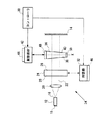
ここで図4を参照して、他の実施形態における外部共振器レーザ34が示される。同様の参照番号は同様の部品を示すために用いられる。レーザ34はチャネル・セレクタを備え、これはウェッジ・エタロン36として図4に示される。ウェッジ・エタロン36は干渉フィルタとして動作し、平行では無い反射面38、40によってテーパ状の形状を有する。図4に示されるウェッジ・エタロン36は、外部共振器レーザに関する本発明において使用され得るチャネル・セレクタの一例に過ぎず、ウェッジ・エタロン36はテーパ状の透明な基板、隣接する透明な基板の反射面の間のテーパ状エアギャップ、傾斜した薄膜干渉フィルタ、格子、電気光学同調器、バーニヤ付きの同調デバイスあるいは他のチャネルセレクター・デバイスを含んで良い。チャネル選択の際にエアギャップ・ウェッジ・エタロンを使用する例が米国特許第6108355号明細書に記載されており、該明細書中において、「ウェッジ」とは隣接した基板によって画定されるテーパ状のエアギャップである。格子の角度調節によって同調される枢動的に調節可能な格子装置をチャネル・セレクタとして使用する事、また、電圧を選択的に印加する事によって同調される電気光学的な同調チャネル・セレクタを外部共振器レーザに使用する事が、2001年3月21日に出願された発明者アンドリュー・ダイバーによる米国特許出願番号第09/814646号に記載されている。並進的に同調された傾斜した薄膜干渉フィルタをチャネル・セレクタとして使用する事が、米国特許出願番号第09/814646号、およびホプキンス等によって本願と共に出願された「傾斜した薄膜ウェッジ干渉フィルタ、およびレーザ同調に対して使用する際の方法」という名称の米国特許出願番号第09/990412号に記載される。前述の開示は、参照によって本願に援用される。
Referring now to FIG. 4, an
ウェッジ・エタロン36によって画定される通過帯域は、グリッド・エタロン24によって画定される通過帯域よりも実質的に広く、ウェッジ・エタロン36のより広い通過帯域が、グリッド・エタロン24によって画定される最短波長のチャネルと最長波長のチャネルの間の波長との差と実質的に対応する周期を有する。換言すれば、ウェッジ・エタロン36の自由スペクトル領域は、グリッド・エタロン24によって画定される波長グリッドの全ての波長領域と対応する。ウェッジ・エタロン36は、特定の選択されたチャネルに隣接するチャネルを抑制するようなフィネスを有する。
The passband defined by the
ウェッジ・エタロン36は、ウェッジ・エタロン36の面38、40間の光学厚さを変える事により、複数の通信チャネルの中から1つを選択するために使用される。これは、x軸に沿ってウェッジ・エタロン36を変位させることにより達成される。x軸は、ウェッジ・エタロン36のテーパの方向と略平行であり、光路22および外部共振器レーザ34の光軸に対して略垂直である。ウェッジ・エタロン36によって画定される通過帯域のそれぞれによってチャネルが選択可能となり、また、ウェッジ・エタロン36が光路22中に押し込まれる方向に変位するにつれて、光路22に沿って移動するビームはウェッジ・エタロン36のより厚い部分を貫通することになり、これによって、より長い波長チャネルにおける、相対する面38、40間の建設的干渉が得られる。ウェッジ・エタロン36が光路22から引き出される方向に変位するにつれて、ビームはウェッジ・エタロン36より薄い部分を貫通し、より短い波長チャネルに対応する通過帯域を光路22に露出する。上述したように、ウェッジ・エタロン36の自由スペクトル領域は、グリッド・エタロン24の完全な波長の範囲に対応している。その結果、全ての波長グリッドの領域において、通信帯域内の単一の損失最小に同調される事が可能である。グリッド・エタロン24およびウェッジ・エタロン36からゲイン媒体12への統合化されたフィードバックによって、選択されたチャネルの中心波長においてレーザ光線を発することを可能にする。全同調レンジに渡って、ウェッジ・エタロン36の自由スペクトル領域はグリッド・エタロン24の自由スペクトル領域より広い。
The
ウェッジ・エタロン36は、選択されたチャンネルに応じてウェッジ・エタロン36を調節可能に位置調節するように構成・構築された駆動部材または同調器42を含む同調装置により位置を変えられることによって同調され、続いて、選択されたチャネルは、上述されたように、グリッド・エタロン24の位置調節に由来する通信グリッドによって決定される。同調器42は、例えばウェッジ・エタロン36の精密並進運動に好適なハードウェアと共にステッパーモータを備えても良い。もしくは、同調器42は、直流サーボモーター、ソレノイド、ボイスコイル・アクチュエーター、圧電アクチュエータ、超音波ドライバ、形状記憶デバイス、または同様の往復アクチュエータのように、様々な種類のアクチュエータを含んでも良い。アクチュエータの種類は上記されてものに限定されない。ウェッジ・エタロン36以外の異なる種類のチャネル・セレクタが本発明に使用される場合、波長同調器42はチャネル・セレクタを同調するためにそれに応じて構成されるであろう。
The
ウェッジ・エタロン同調器42はコントローラ30に動作可能なように接続され、コントローラ30は、同調器42によるウェッジ・エタロン36の位置決めを制御する信号を供給する。コントローラ30はデータ処理装置およびメモリ(図示されない)を備えて良く、選択可能なチャネル波長に対応するウェッジ・エタロン36用の位置情報のルックアップテーブルが内部に保存される。上記述されるように、グリッド・エタロン24の制御に使用される同一のコントローラ30によってウェッジ・エタロン36が制御されるように図示されている。しかしながら、別のコントローラがウェッジ・エタロン36用に使用されても良い。
The
外部共振器レーザ34がグリッド・エタロン24によって決定された異なる通信チャネルに同調される時、コントローラ30はルックアップテーブル中の位置データに従って同調器42に信号を送り、同調器42はウェッジ・エタロン36を正確な位置まで平行移動させるか、さもなければ調節し、光路22中に位置するウェッジ・エタロン36の位置における光学厚さによって、選択されたチャネルのための建設的干渉が得られるようになされる。同調器42によってウェッジ・エタロン36を正確・確実に位置調節するために、直線エンコーダ44がウェッジ・エタロン36および同調器42に関して使用されてもよい。同調器32によるグリッド・エタロン24の正確な位置調節を保証するために、エンコーダ46がグリッド・エタロン同調器32に関してさらに含まれていても良い。
When the
ウェッジ・エタロン36は、光学上検知可能で、ウェッジ・エタロン36が最長または最短のチャネル波長に位置決めされた際にウェッジ・エタロン36の位置を確認するために用いられる不透明領域48、50を、ウェッジ・エタロン36の両端に備えていても良い。不透明領域48、50によって、ウェッジ・エタロン36の位置決めにおいて使用可能なエンコーダ・メカニズムが付加的に提供される。不透明領域48、50のいずれかが光路22に進入するようにウェッジ・エタロン36が位置決めされる時、不透明領域48、50は、光路に沿ってビームを遮断するか減衰させる。以下詳細される通り、この光の減衰は、光学的に検知可能であるか、ゲイン媒体12の両端の電圧変調を監視することによって検知可能である。ウェッジ・エタロン36上の不透明領域48、50の位置は正確に決定され得るので、コントローラ30は不透明領域48、50が光路22に何時進入するかを予想する事が出来る。予想されたポイント以外に光路22中の不透明領域48、50が出現すると言う事は、エンコーダのエラーを表しており、また、コントローラ30は、光路22中の不透明領域48、50の検知された位置に基づいて、適切な補正を行う事が出来る。別の不透明領域(図示されない)が、ウェッジ・エタロン36の任意の他の位置に更に含まれていても良い。
The
外部共振器レーザ34の様々な光学コンポーネントの間の相対的なサイズ、形、および距離は、幾つかの例においては明瞭性を保つために誇張して示されている場合があり、必ずしも等縮尺であるとは限らない。外部共振器レーザ34は、焦点を合わせる要素およびコリメーション要素、外部共振器レーザ34の様々な要素に関連した偽フィードバックを除去するように構成される偏光光学系と言った追加の構成要素(図示されず)を備えても良い。
The relative size, shape, and distance between the various optical components of the
外部共振器レーザ34のグリッド・エタロン24、ウェッジ・エタロン36、および裏面18およびエンドミラー14によって画定される外部共振器の通過帯域の関係の一例を示すグラフが図5に示され、図5は、外部共振器通過帯域PB1、グリッド・エタロン通過帯域PB2およびウェッジ・エタロン通過帯域PB3を示す。相対ゲインが縦軸に、波長が横軸に示される。グリッド・エタロン通過帯域PB2は、例えば、図3に示される通信グリッドのうちの1つによって画定される通過帯域に相当して良い。図5は、典型的な0.5ナノメートル(nm)のグリッド間隔を示す。
A graph illustrating an example of the external resonator passband relationship defined by the
図5から明らかなように、ウェッジ・エタロン36の自由スペクトル領域(FSRChannel Sel)は、グリッド・エタロン24の自由スペクトル領域(FSRGrid Gen)より大きく、グリッド・エタロン24の自由スペクトル領域(FSRGrid Gen)は、外部共振器の自由スペクトル領域(FSRCavity)より大きい。外部共振器通過帯域PB1のピークは、グリッド・エタロン24の波長グリッドによって画定された通過帯域PB2の中心波長と周期的に一致する。全ての波長グリッドの通過帯域PB2に渡って広がるウェッジ・エタロン36の通過帯域PB3のピークは1つである。図5に示される特定の例において、グリッド・エタロン24によって画定される波長グリッドは、0.5nm(62GHz)間隔で離間し、最短波長チャネルが1532nm、最長波長チャネルが1563.5nmであって、64個のチャネルに渡って延長している。この面間隔は、上記述されるようなグリッド・エタロン24を同調することにより、本発明によって同調され得る。
As is apparent from FIG. 5, the free spectral range (FSR Channel Sel) of
グリッド・エタロン24およびウェッジ・エタロン36のフィネスは、隣接しているモードまたはチャネルの減衰を決定する。上述されたように、フィネスは、自由スペクトル領域を半値全幅で割った値と等しい。即ち、フィネス=FSR/FWHMである。グリッド・エタロン通過帯域PB2の半値全幅が図5bに示され、ウェッジ・エタロン通過帯域PB3の半値全幅が図5cに示される。外部共振器内においてグリッド・エタロン24およびウェッジ・エタロン36の位置を調節する事によって、サイドモード抑圧比が向上する。
The finesse of
1549.5nmおよびそれに隣接する1550nmに中心が合わせられたチャネル間におけるウェッジ・エタロン36の通過帯域PB3の同調の例が、図6のグラフによって示される。また、グリッド・エタロン24によって為されたチャネルの選択と、隣接するチャネルまたはモードの減衰も示されている。図5に示される外部共振器の通過帯域PB1は、明瞭性を保つために図6においては省略される。グリッド・エタロン24は、グリッド・チャネル間隔に対応する外部共振器の周期的な縦モードを選択する一方で、隣接するモードは遮断する。ウェッジ・エタロン36は、該波長グリッド中の特定のチャネルを選択し、他の全てのチャネルを遮断する。選択されたチャネルあるいはレーザ光線のモードは、チャネル間隔のプラスマイナス約半分の範囲のフィルタ・オフセットにより、1つの特定のチャネルに固定される。チャネルのオフセットがより大きい場合、レーザ光線のモードは隣接するチャネルへとジャンプする。
An example of tuning the passband PB3 of the
図6aにおいて、ウェッジ・エタロン通過帯域PB3は、1549.5nmのグリッド・チャネルに合わせられている。1549.5nmにおける通過帯域PB2に関する相対ゲインは高いが、その一方で隣接している1549.0nmおよび1550.0nmにおける通過帯域PB2に関する相対ゲインレベルは、選択された1549.5nmのチャネルに比べて抑圧されている。1550.5nmおよび1548.5nmにおける通過帯域PB2に関するゲインは一層抑圧されている。1点鎖線は、ウェッジ・エタロン36によって抑圧されていない状態の通過帯域PB2の相対ゲインを示す。
In FIG. 6a, the wedge etalon passband PB3 is tuned to a grid channel of 1549.5 nm. The relative gain for passband PB2 at 1549.5 nm is high, while the relative gain level for adjacent passband PB2 at 1549.0 nm and 1550.0 nm is suppressed compared to the selected 1549.5 nm channel. Has been. The gain for the passband PB2 at 1550.5 nm and 1548.5 nm is further suppressed. The alternate long and short dash line indicates the relative gain of the pass band PB2 that is not suppressed by the
図6bはウェッジ・エタロン通過帯域PB3が、チャネル切り替えの最中に1549.5nmおよび1550.0nmのチャネルの間に位置する状態を示す。1549.5nmおよび1550.0nmにおける通過帯域PB2に関する相対ゲインは両方とも高く、どちらも抑制されていない。1549.0nmおよび1550.5nmにおける通過帯域PB2に関する相対ゲインのレベルは、1549.5nmおよび1550.0nmのチャネルに比べれば抑圧されている。1点鎖線は、ウェッジ・エタロン36によって抑圧されていない状態の通過帯域PB2の相対ゲインを示す。
FIG. 6b shows a situation where the wedge-etalon passband PB3 is located between the 1549.5 nm and 1550.0 nm channels during channel switching. The relative gains for passband PB2 at 1549.5 nm and 1550.0 nm are both high and neither is suppressed. The relative gain level for passband PB2 at 1549.0 nm and 1550.5 nm is suppressed compared to the 1549.5 nm and 1550.0 nm channels. The alternate long and short dash line indicates the relative gain of the pass band PB2 that is not suppressed by the
図6cは、ピークが1550.0nmのグリッド・チャネルに合わせられているウェッジ・エタロン通過帯域PB3を示し、1550.0nmにおける通過帯域PB2に関する相対ゲインは高いが、その一方で隣接している1549.5nmおよび1550.5nmにおける通過帯域PB2に関する相対ゲインレベルは、選択された1520.0nmのチャネルに比べて抑圧されており、1551.0nmおよび1549.0nmにおける通過帯域PB2に関するゲインは更に抑圧されている。再び、1点鎖線は、ウェッジ・エタロン36によって抑圧されていない状態の通過帯域PB2の相対ゲインを示す。
FIG. 6c shows a wedge etalon passband PB3 that is tuned to a grid channel with a peak of 1550.0 nm, while the relative gain for the passband PB2 at 1550.0 nm is high, while adjacent 1549. The relative gain level for the passband PB2 at 5 nm and 1550.5 nm is suppressed compared to the selected 1520.0 nm channel, and the gain for the passband PB2 at 1551.0 nm and 1549.0 nm is further suppressed. . Again, the alternate long and short dash line indicates the relative gain of the passband PB2 that is not suppressed by the
図5および図6に示される0.5nmのグリッド間隔は、外部共振器レーザ34で使用可能な通信グリッドの1つを示しているのに過ぎない。前述されたように、グリッド・エタロン24は、通信グリッドを同調する為に、位置、熱、音響、光学、圧力、電圧調節のメカニズムあるいは他の制御メカニズムにより同調されて良い。0.25nm間隔で離間している2つのポジションの間で通信グリッドを同調する事により、図示された公称0.5nmのグリッドから0.25nmのグリッド間隔が達成され得る。偶数番目のチャネルから奇数番目のチャネルへの転移がある場合は常にグリッドの再同調が必要となる。他に選択されたグリッド間隔におけるウェッジ・エタロン36による外部共振器レーザ34の同調は、通常は上述されるのと同じ様態で行なわれる。
The 0.5 nm grid spacing shown in FIGS. 5 and 6 represents only one of the communication grids that can be used with the
ここで図7を参照して、本発明における外部共振器レーザ装置52の他の実施形態が示される。同様の参照番号は同様の部品を示すために用いられる。レーザ装置52では、ゲイン媒体12は電極54、56と共に示され、電極54、56は、駆動電流源58からの電流をゲイン媒体12の両端に供給するように位置している。ゲイン媒体12の両端の電流レベルを選択的に制御可能にするために、駆動電流源58がコントローラ30に操作可能なように接続されて良い。電圧センサが電極54、56のうちの1つに操作可能なように接続され、レーザ運転中にゲイン媒体12の両端の電圧変調を監視するように構成される。同様に、電圧センサ60は、コントローラ30に操作可能なように接続される。
Referring now to FIG. 7, another embodiment of an external
外部共振器同調器62は、コントローラ30およびエンドミラー14に操作可能なように接続される。同調器62は、例えば、ゲイン媒体12の出力面18とエンドミラー14との間の光共振器または経路長を制御するエンドミラー14の位置を決定するように構成されたステッパーモータあるいは他の往復型アクチュエーターデバイスを備えても良い。エンドミラー14の正確な位置決めを保証するために、エンコーダ64が外部共振器同調器62に関して含まれていても良い。あるいは、別のコントローラ(図示されない)が、外部共振器同調器62を制御するために使用されても良い。
ある実施形態において、外部共振器同調器62は、熱的に同調可能な補償器部材(図示されない)を備えても良く、熱的に同調可能な補償器部材は、コントローラ30から熱的に同調可能な補償器部材に接続される熱電コントローラ(図示されない)までの光共振器調節信号に従って熱的な補償器部材を加熱または冷却する事により、エンドミラー14の位置を決めるために構成される。外部共振器レーザ中のエンドミラーおよび他の光学コンポーネントを位置的に調節するための熱制御同調部材の使用もまた、2001年3月21日に出願された発明者アンドリュー・ダイバーによる米国特許出願番号第09/814646号、および、これと平行して出願された、発明者マーク・ライス等による「外部共振器の能動的温度同調を伴うレーザ装置」という名称の米国特許出願番号第09/900443号に記載され、参照により本願に援用される。
In certain embodiments, the
レーザ装置52の外部共振器光路長もまた、ゲイン媒体12の位置調節、つまり、出力面18がエンドミラー14に対して移動する事によって同調されて良い。外部共振器の調節もまた、外部共振器内に存在して外部共振器に光学的に結合している電気光学部材(図示されない)の電圧調節によって達成されて良く、外部共振器の有効光学厚さ、および従って外部共振器の光路長を、電気光学部材の両端に選択的に電圧を印加する事によって制御させる事が出来る。外部共振器の同調のために電気光学部材を使用する事もまた、発明者ダイバー等による「ゲイン媒体の両端の電圧によるレーザ損失の評価および調節」という名称の米国特許出願番号第09/990426号によって開示され、参照によって本願に援用される。
The external resonator optical path length of the
外部共振器レーザ装置52の運転において、ゲイン媒体12の両端の電圧は電圧センサ60によって監視され、コントローラ30に伝達される。グリッド・エタロン24、ウェッジ・エタロン36およびエンドミラーからの光学のフィードバックが出力面16を経由してゲイン媒体へ導入されるので、グリッド・エタロン24、ウェッジ・エタロン36およびエンドミラーに関する光損失は、センサ60によって監視されるのと同様に、ゲイン媒体12の両端の電圧によって検知可能である。損失が生じる場合、誤差信号はコントローラ30によって検知された電圧から導出され、誤差信号をヌル化するためのグリッド・エタロン24、ウェッジ・エタロン36またはエンドミラー14の調節の必要に応じて、グリッド・ジェネレータ同調器32、ウェッジ・エタロン同調器42、および(または)外部共振器同調器62に相応の補償信号を送信する。
In operation of the external
ある実施形態において、周波数ディザの形を取る信号の変調が、エンドミラー14に接続されるか、さもなければレーザ装置52の外部共振器に関連するディザ部材(図示されず)によって、外部共振器レーザ装置52へ導入される。信号の変調は、例えば、約20kHzの周波数変調を含んで良く、エンドミラー14に適切に接続された圧電、電気光学、または音響光学デバイスによって生成されて良い。この方式によるレーザ外部共振器の光路長の変調によって、外部共振器からのゲイン媒体12へ光学のフィードバックにより電圧センサ60によって検知し得る外部共振器レーザ装置52の出力パワーにおける強度変化が生成される。これらの強度変化は、ウェッジ・エタロン36およびグリッド・エタロン24によって画定された通過帯域の中心波長における外部共振器モードのアラインメントに応じて、その振幅およびフェーズエラーが異なるであろう。換言すれば、変調信号における強度変化および移相によって、外部共振器の損失を評価し、かつ外部共振器光路長の調節用の対応する誤差信号を生成するための有効な方法が提供される。従って、コントローラ30は、周波数ディザによって導入された変調から誤差信号を導出し、コントローラ30に補償信号を伝え、これに対応して、外部共振器同調器62に命令を出し、エンドミラー14の位置を決めることによって外部共振器が調節されるようにする。誤差信号の決定および外部共振器の調節に関して変調信号の強度変化およびフェーズエラーを使用することもまた、発明者ダイバー等による「ゲイン媒体の両端の電圧によるレーザ損失の評価および調節」という名称の米国特許出願番号第09/990426号によって開示され、参照によって本願に援用される。
In some embodiments, the modulation of the signal in the form of a frequency dither is connected to the
本発明は特定の実施例に関して記載された一方、本発明の真の精神と範囲から逸脱することなく、さまざまな修正がなされ得、均等物によって置換され得る事が当業者によって理解されるべきである。加えて、特定の状況、材料、組成物、プロセス、工程段階を、本発明の目的、精神および範囲に適応させるために、多くの変更が成され得る。この種の変更の全てが、添付の特許請求の範囲の範囲内であることが意図されている。 While the invention has been described with reference to specific embodiments, it should be understood by those skilled in the art that various modifications can be made and replaced by equivalents without departing from the true spirit and scope of the invention. is there. In addition, many modifications may be made to adapt a particular situation, material, composition of matter, process, process step, to the objective, spirit and scope of the present invention. All such modifications are intended to be within the scope of the appended claims.
Claims (16)
第1出力面および第2出力面を有し、前記第1出力面からビームを光路に沿って放射する活性領域を有するゲイン媒体と、
前記光路中に位置し、前記第2出力面と共に外部共振器を画定する反射器と、
前記光路中に位置するグリッド・エタロンと、
前記グリッド・エタロンに動作可能に接続され、前記外部共振器レーザの運転中に、前記グリッド・エタロンの自由スペクトル領域に対応する離間した複数の伝送帯を画定する、第1の通信グリッドから第2の通信グリッドへ、前記グリッド・エタロンを調節するグリッド・エタロン同調器と、
選択可能な複数の通信グリッドに対応する前記グリッド・エタロン用の調節パラメータを保存しており、前記外部共振器レーザの運転中に、前記グリッド・エタロン同調器に信号を送り、前記調節パラメータに従って前記グリッド・エタロンを、前記第1の通信グリッドから前記第2の通信グリッドへ調節させるコントローラと、
前記光路中に位置するウェッジ・エタロンと、
前記ウェッジ・エタロンに動作可能に接続され、前記複数の伝送帯のうちの1つの伝送帯に前記ウェッジ・エタロンを同調させるチャネル・セレクタ同調器と、
を備え、
前記ウェッジ・エタロンは、前記ウェッジ・エタロンの位置を確認するために用いられる不透明領域を、前記ウェッジ・エタロンの両端に有し、
前記不透明領域を利用して前記ウェッジ・エタロンの基準位置を決定する装置。An external cavity laser device,
A gain medium having a first output surface and a second output surface, and having an active region that emits a beam from the first output surface along an optical path;
A reflector located in the optical path and defining an external resonator with the second output surface;
A grid etalon located in the optical path;
A first communication grid to a second operably connected to the grid etalon and defining a plurality of spaced transmission bands corresponding to a free spectral region of the grid etalon during operation of the external cavity laser; A grid etalon tuner for adjusting the grid etalon,
Storing adjustment parameters for the grid etalon corresponding to a plurality of selectable communication grids, and sending a signal to the grid etalon tuner during operation of the external cavity laser; A controller for adjusting a grid etalon from the first communication grid to the second communication grid;
A wedge etalon located in the optical path;
A channel selector tuner operably connected to the wedge etalon for tuning the wedge etalon to one of the plurality of transmission bands;
With
The wedge etalon, the opaque area used to check the position of the wedge etalon, possess at both ends of the wedge etalon,
An apparatus for determining a reference position of the wedge etalon using the opaque region .
第1出力面および第2出力面および活性領域を有する外部共振器レーザを提供し、
光路に沿って、前記第1出力面の活性領域からコヒーレントなビームを放射し、
エンドミラーが前記光路中に位置し、
前記エンドミラーおよび前記第2出力面が外部共振器を画定し、
グリッド・エタロンの前記光路に関する位置決めをし、
前記外部共振器レーザの運転中に、選択可能な複数の通信グリッドに対応する前記グリッド・エタロン用の調節パラメータを保存しているコントローラから、グリッド・エタロン同調器に信号を送り、
前記外部共振器レーザの運転中に、前記調節パラメータに従って、前記グリッド・エタロンの自由スペクトル領域に対応する離間した複数の波長通過帯域を画定する、第1の選択可能な通信グリッドから第2の選択可能な通信グリッドへ、前記グリッド・エタロンを変化させ、
前記光路に関して位置するウェッジ・エタロンであって、前記ウェッジ・エタロンの位置を確認するために用いられる不透明領域を両端に有する前記ウェッジ・エタロンの基準位置を、前記不透明領域を利用して決定し、前記ウェッジ・エタロンを同調させ、
前記ウェッジ・エタロンが同調可能な透過ピークを生成し、
前記同調可能な透過ピークと前記複数の波長通過帯域のうちの1つの波長通過帯域とのアライメントを取ることによって、前記透過ピークを経由してチャネル選択を行う、方法。A method for producing a tunable and coherent light output comprising:
Providing an external cavity laser having a first output surface and a second output surface and an active region;
A coherent beam is emitted from the active region of the first output surface along an optical path;
An end mirror is located in the optical path,
The end mirror and the second output surface define an external resonator;
Positioning for the optical path of the grid etalon,
During operation of the external cavity laser, a signal is sent to the grid etalon tuner from a controller storing adjustment parameters for the grid etalon corresponding to a plurality of selectable communication grids,
During operation of the external cavity laser, a second selection from a first selectable communication grid that defines a plurality of spaced wavelength passbands corresponding to the free spectral region of the grid etalon according to the tuning parameter Change the grid etalon to a possible communication grid,
A wedge etalon positioned with respect to the optical path, wherein the reference position of the wedge etalon having an opaque region at both ends used to confirm the position of the wedge etalon is determined using the opaque region, Tune the wedge etalon,
The wedge etalon produces a tunable transmission peak;
A method for performing channel selection via the transmission peak by aligning the tunable transmission peak with one of the plurality of wavelength pass bands.
前記グリッド・エタロン同調器が、前記グリッド・エタロンの前記屈折率を変更することにより、前記グリッド・エタロンの同調を行うべく、前記グリッド・エタロンに選択可能な電圧を供給するために制御可能である、請求項1乃至請求項3のいずれかに記載の装置。The grid etalon is fabricated from an electro-optic material having a voltage dependent refractive index;
The grid etalon tuner is controllable to provide a selectable voltage to the grid etalon to tune the grid etalon by changing the refractive index of the grid etalon. An apparatus according to any one of claims 1 to 3.
活性領域を有し、第1および第2出力面を有し、前記第1出力面の前記活性領域から光路に沿ってコヒーレントなビームを放射するゲイン媒体と、
前記ゲイン媒体の前記第1出力面と相対して配置され、第2出力面とともに外部レーザ共振器を画定するエンドミラーと、
前記光路中に位置するグリッド・ジェネレータと、
前記装置の運転中に、それぞれの選択可能な通信グリッドによって画定されるチャネル間隔に応じて一定の波長間隔を有する複数の波長通過帯域を画定する、第1の通信グリッドから第2の通信グリッドへ、前記グリッド・ジェネレータを調節するために前記グリッド・ジェネレータに動作可能に接続されたグリッド・ジェネレータ同調器と、
選択可能な複数の通信グリッドに対応する前記グリッド・ジェネレータ用の調節パラメータを保存しており、前記調節パラメータに従って前記第1の通信グリッドから前記第2の通信グリッドへ前記グリッド・ジェネレータを調節するべく、外部共振器レーザの運転中に、前記グリッド・ジェネレータ同調器に信号を供給するために、前記グリッド・ジェネレータ同調器に接続されるコントローラと、
前記コントローラに動作可能なように接続され、複数の波長通過帯域のうちの1つの波長通過帯域と、生成する透過ピークとのアライメントを取るウェッジ・エタロンと、
を備え、
前記ウェッジ・エタロンは、前記ウェッジ・エタロンの位置を確認するために用いられる不透明領域を、前記ウェッジ・エタロンの両端に有し、
前記不透明領域を利用して前記ウェッジ・エタロンの基準位置を決定する装置。A device,
A gain medium having an active region, having first and second output surfaces, and emitting a coherent beam from the active region of the first output surface along an optical path;
An end mirror positioned relative to the first output surface of the gain medium and defining an external laser resonator with the second output surface;
A grid generator located in the optical path;
During operation of the apparatus, from a first communication grid to a second communication grid that defines a plurality of wavelength passbands having a constant wavelength spacing depending on the channel spacing defined by each selectable communications grid. A grid generator tuner operatively connected to the grid generator for adjusting the grid generator;
An adjustment parameter for the grid generator corresponding to a plurality of selectable communication grids is stored, and the grid generator is adjusted from the first communication grid to the second communication grid according to the adjustment parameter. A controller connected to the grid generator tuner for providing signals to the grid generator tuner during operation of the external cavity laser;
A wedge etalon that is operatively connected to the controller and that aligns one of the plurality of wavelength passbands with a generated transmission peak;
With
The wedge etalon, the opaque area used to check the position of the wedge etalon, possess at both ends of the wedge etalon,
An apparatus for determining a reference position of the wedge etalon using the opaque region .
前記グリッド・ジェネレータ同調器が、前記グリッド・ジェネレータを回転させることにより前記グリッド・ジェネレータを同調する、請求項8に記載の装置。The grid generator comprises a grid etalon;
The apparatus of claim 8, wherein the grid generator tuner tunes the grid generator by rotating the grid generator.
前記駆動電流源が、前記ゲイン媒体に供給される電流レベルを選択的に制御する、請求項8又は請求項9に記載の装置。A drive current source connected to the gain medium and the controller;
10. An apparatus according to claim 8 or claim 9, wherein the drive current source selectively controls the current level supplied to the gain medium.
前記電圧センサが、前記ゲイン媒体の両端の電位差に対応して、前記コントローラに電圧フィードバック信号を供給する、請求項8乃至請求項10のいずれかに記載の装置。A voltage sensor connected to the gain medium and the controller;
The apparatus according to claim 8, wherein the voltage sensor supplies a voltage feedback signal to the controller in response to a potential difference between both ends of the gain medium.
前記外部共振器同調器が、前記エンドミラーと前記ゲイン媒体との間の光路長を調節するために前記エンドミラーの位置を決める、請求項8乃至請求項12のいずれかに記載の装置。An external resonator tuner connected to the end mirror and the controller;
13. An apparatus according to any of claims 8 to 12, wherein the external resonator tuner determines the position of the end mirror to adjust the optical path length between the end mirror and the gain medium.
Applications Claiming Priority (2)
| Application Number | Priority Date | Filing Date | Title |
|---|---|---|---|
| US09/900,474 US6822979B2 (en) | 2001-07-06 | 2001-07-06 | External cavity laser with continuous tuning of grid generator |
| PCT/US2002/021415 WO2003005503A2 (en) | 2001-07-06 | 2002-07-05 | External cavity laser with continuous tuning of grid generator |
Publications (3)
| Publication Number | Publication Date |
|---|---|
| JP2004535069A JP2004535069A (en) | 2004-11-18 |
| JP2004535069A5 JP2004535069A5 (en) | 2006-04-13 |
| JP4204972B2 true JP4204972B2 (en) | 2009-01-07 |
Family
ID=25412590
Family Applications (1)
| Application Number | Title | Priority Date | Filing Date |
|---|---|---|---|
| JP2003511356A Expired - Lifetime JP4204972B2 (en) | 2001-07-06 | 2002-07-05 | External cavity laser with continuous tuning of grid generator |
Country Status (9)
| Country | Link |
|---|---|
| US (1) | US6822979B2 (en) |
| EP (1) | EP1405381B1 (en) |
| JP (1) | JP4204972B2 (en) |
| KR (1) | KR100681543B1 (en) |
| CN (1) | CN1251367C (en) |
| AT (1) | ATE468638T1 (en) |
| AU (1) | AU2002318215A1 (en) |
| DE (1) | DE60236435D1 (en) |
| WO (1) | WO2003005503A2 (en) |
Families Citing this family (38)
| Publication number | Priority date | Publication date | Assignee | Title |
|---|---|---|---|---|
| US6512385B1 (en) * | 1999-07-26 | 2003-01-28 | Paul Pfaff | Method for testing a device under test including the interference of two beams |
| US7027472B2 (en) * | 2001-07-19 | 2006-04-11 | Axsun Technologies, Inc. | Fixed wavelength single longitudinal mode coolerless external cavity semiconductor laser system |
| US8462350B2 (en) | 2001-12-06 | 2013-06-11 | Attofemto, Inc. | Optically enhanced holographic interferometric testing methods for the development and evaluation of semiconductor devices, materials, wafers, and for monitoring all phases of development and manufacture |
| US7733499B2 (en) | 2001-12-06 | 2010-06-08 | Attofemto, Inc. | Method for optically testing semiconductor devices |
| US9952161B2 (en) | 2001-12-06 | 2018-04-24 | Attofemto, Inc. | Methods for obtaining and analyzing digital interferometric data for computer testing and developing semiconductor and anisotropic devices and materials |
| SE524828C2 (en) * | 2002-06-06 | 2004-10-12 | Alfa Exx Ab | Resonator |
| US6636536B1 (en) * | 2002-09-30 | 2003-10-21 | J. Gilbert Tisue | Passive thermal compensation for wavelength agile laser tuners |
| WO2004070893A2 (en) * | 2003-02-05 | 2004-08-19 | Gws-Photonics Ltd. | External cavity tunable laser and control |
| GB2418028B (en) * | 2003-05-07 | 2007-08-01 | Qinetiq Ltd | Dynamic optical reflector and interrogation system |
| EP1586854A3 (en) * | 2004-04-15 | 2006-02-08 | Davidson Instruments | Interferometric signal conditioner for measurement of the absolute length of gaps in a fiber optic Fabry-Pérot interferometer |
| US7492463B2 (en) | 2004-04-15 | 2009-02-17 | Davidson Instruments Inc. | Method and apparatus for continuous readout of Fabry-Perot fiber optic sensor |
| WO2006008873A1 (en) * | 2004-07-15 | 2006-01-26 | Nec Corporation | External resonator variable wavelength laser |
| EP1674833A3 (en) | 2004-12-21 | 2007-05-30 | Davidson Instruments, Inc. | Fiber optic sensor system |
| EP1681540A1 (en) | 2004-12-21 | 2006-07-19 | Davidson Instruments, Inc. | Multi-channel array processor |
| US7570844B2 (en) * | 2005-01-18 | 2009-08-04 | Doron Handelman | Photonic integrated circuit device and elements thereof |
| US20060274323A1 (en) | 2005-03-16 | 2006-12-07 | Gibler William N | High intensity fabry-perot sensor |
| US20070133647A1 (en) * | 2005-09-30 | 2007-06-14 | Andrew Daiber | Wavelength modulated laser |
| US7684051B2 (en) | 2006-04-18 | 2010-03-23 | Halliburton Energy Services, Inc. | Fiber optic seismic sensor based on MEMS cantilever |
| EP2021747B1 (en) | 2006-04-26 | 2018-08-01 | Halliburton Energy Services, Inc. | Fiber optic mems seismic sensor with mass supported by hinged beams |
| US8115937B2 (en) | 2006-08-16 | 2012-02-14 | Davidson Instruments | Methods and apparatus for measuring multiple Fabry-Perot gaps |
| CA2676246C (en) | 2007-01-24 | 2013-03-19 | Halliburton Energy Services, Inc. | Transducer for measuring environmental parameters |
| US8564783B2 (en) * | 2008-05-15 | 2013-10-22 | Axsun Technologies, Inc. | Optical coherence tomography laser with integrated clock |
| FI20105476A (en) | 2010-04-30 | 2011-10-31 | Vaisala Oyj | Method and equipment for measurement of atmospheric humidity, temperature profile or cloud height |
| CN102780158B (en) * | 2011-05-09 | 2014-08-06 | 中国科学院深圳先进技术研究院 | Tunable external-cavity semiconductor laser |
| WO2014000311A1 (en) * | 2012-06-30 | 2014-01-03 | 华为技术有限公司 | External cavity laser |
| US8873963B2 (en) | 2012-07-25 | 2014-10-28 | Doron Handelman | Apparatus and methods for generating and receiving optical signals at substantially 100Gb/s and beyond |
| US9054955B2 (en) | 2012-12-30 | 2015-06-09 | Doron Handelman | Apparatus and methods for enabling recovery from failures in optical networks |
| US20140255622A1 (en) * | 2013-03-05 | 2014-09-11 | Ruth Smith | Customized building opening cover |
| CN103515840A (en) * | 2013-08-07 | 2014-01-15 | 苏州旭创科技有限公司 | External-cavity laser device with tunable wave length |
| US9344187B2 (en) | 2013-09-17 | 2016-05-17 | Doron Handelman | Apparatus and methods for enabling recovery in optical networks |
| CN103633547B (en) * | 2013-12-20 | 2017-01-25 | 武汉光迅科技股份有限公司 | Wavelength-tunable external cavity laser |
| CN103633558B (en) | 2013-12-20 | 2016-04-20 | 武汉光迅科技股份有限公司 | Adopt the wideband adjustable outside cavity gas laser of small-sized MEMS mirror |
| GB201410003D0 (en) * | 2014-06-05 | 2014-07-16 | Renishaw Plc | Laser device |
| US9972964B2 (en) | 2016-04-19 | 2018-05-15 | Lumentum Operations Llc | Polarization-based dual channel wavelength locker |
| US10050405B2 (en) | 2016-04-19 | 2018-08-14 | Lumentum Operations Llc | Wavelength locker using multiple feedback curves to wavelength lock a beam |
| CN107645119A (en) * | 2017-10-18 | 2018-01-30 | 哈尔滨工业大学 | A kind of method of computer control laser output wavelength |
| US10670803B2 (en) | 2017-11-08 | 2020-06-02 | Lumentum Operations Llc | Integrated wavelength monitor |
| EP3787134A4 (en) * | 2018-04-26 | 2022-01-19 | Sumitomo Electric Device Innovations, Inc. | Optical semiconductor device and method of controlling same |
Family Cites Families (122)
| Publication number | Priority date | Publication date | Assignee | Title |
|---|---|---|---|---|
| US3967211A (en) | 1974-01-17 | 1976-06-29 | Jersey Nuclear-Avco Isotopes, Inc. | Laser wavelength stabilization |
| EP0001714B1 (en) | 1977-10-26 | 1984-03-21 | The Post Office | Control apparatus for a semi-conductor laser device |
| US4410992A (en) | 1980-03-26 | 1983-10-18 | Laser Science, Inc. | Generation of pulsed laser radiation at a finely controlled frequency by transient regerative amplification |
| JPS57133531A (en) | 1981-02-12 | 1982-08-18 | Agency Of Ind Science & Technol | Optical information processor |
| GB2115217B (en) | 1982-02-09 | 1986-04-03 | Standard Telephones Cables Ltd | Semiconductor lasers |
| US4504950A (en) | 1982-03-02 | 1985-03-12 | California Institute Of Technology | Tunable graded rod laser assembly |
| FI74371C (en) | 1982-06-04 | 1988-01-11 | British Telecomm | Optical transmission. |
| US5124993A (en) | 1984-09-20 | 1992-06-23 | International Sensor Technology, Inc. | Laser power control |
| GB8522821D0 (en) | 1985-09-16 | 1985-10-23 | British Telecomm | Frequency referencing system |
| FR2597971B1 (en) | 1986-04-24 | 1990-10-19 | Photonetics | FIBER OPTIC SENSOR |
| FR2610465A1 (en) | 1987-02-02 | 1988-08-05 | Photonetics | FIBER OPTIC SENSING DEVICE INVOLVING PROPER OPERATION |
| FR2615284B1 (en) | 1987-05-11 | 1992-02-28 | Photonetics | DEVICE FOR THE DETECTION OF VIBRATIONS COMPRISING A MULTIMODE OPTICAL FIBER AS A SENSITIVE ELEMENT |
| WO1989000779A1 (en) | 1987-07-17 | 1989-01-26 | Kabushiki Kaisha Komatsu Seisakusho | Apparatus for controlling laser wavelength |
| FR2618891B1 (en) | 1987-07-31 | 1989-12-15 | Photonetics | METHOD AND DEVICE FOR MEASURING BY ANALYSIS OF A CANNED LUMINOUS SPECTRUM, PARTICULARLY FOR MEASURING A LOW AMPLITUDE DISPLACEMENT OF A MOBILE SURFACE, POSSIBLY REPRESENTATIVE OF THE VARIATION OF A PHYSICAL LARGE CONVERTIBLE IN SUCH A MOVEMENT |
| GB8807385D0 (en) | 1988-03-29 | 1988-05-05 | British Telecomm | Semiconductor device assembly |
| FR2631438B1 (en) | 1988-05-11 | 1991-06-21 | Photonetics | METHOD FOR POSITIONING AN OBJECT RELATIVE TO A PLANE, METHOD FOR MEASURING LENGTH AND DEVICES FOR CARRYING OUT SAID METHODS |
| GB2224389B (en) | 1988-10-20 | 1993-04-21 | Mitsubishi Electric Corp | Laser device with wavelength stabilization control and method of operating the same |
| US5450202A (en) | 1988-11-17 | 1995-09-12 | Tisue; James G. | Adaptive resonant positioner having random access capability |
| US4847853A (en) | 1988-11-17 | 1989-07-11 | United Technologies Corporation | CO2 tea laser having isolated preionization compartments |
| FR2641861B1 (en) | 1989-01-18 | 1993-04-30 | Photonetics | OPTO-ELECTRONIC MEASURING DEVICE |
| FR2645645B1 (en) | 1989-04-06 | 1991-07-12 | Photonetics | IMPROVEMENTS IN METHODS AND DEVICES FOR DETERMINING THE ANGLE OF CONTACT OF A DROP OF LIQUID PLACED ON A SUBSTRATE |
| DE3911473A1 (en) | 1989-04-08 | 1990-10-11 | Kerner Anna | WAVELENGTH STABILIZATION |
| US5050179A (en) | 1989-04-20 | 1991-09-17 | Massachusetts Institute Of Technology | External cavity semiconductor laser |
| FR2650076B1 (en) | 1989-07-20 | 1991-10-04 | Commissariat Energie Atomique | OPTICAL FIBER ACTIVE CHEMICAL SENSOR AND MANUFACTURING METHOD THEREOF |
| FR2654827B1 (en) | 1989-11-17 | 1992-03-20 | Photonetics | FIBER OPTIC MEASUREMENT DEVICE, GYROMETER, NAVIGATION AND STABILIZATION UNIT. |
| US5103457A (en) | 1990-02-07 | 1992-04-07 | Lightwave Electronics Corporation | Elliptical mode cavities for solid-state lasers pumped by laser diodes |
| US5163063A (en) | 1990-02-07 | 1992-11-10 | Copal Co., Ltd. | Semiconductor laser driving circuit |
| FR2660996B1 (en) | 1990-04-17 | 1992-08-07 | Photonetics | FIBER OPTIC MEASURING DEVICE, GYROMETER, NAVIGATION AND STABILIZATION UNIT, CURRENT SENSOR. |
| US5225930A (en) | 1990-05-10 | 1993-07-06 | The United States Of America As Represented By The Secretary Of The Air Force | Comb optical interference filter |
| FR2662245B1 (en) | 1990-05-18 | 1994-05-20 | Photonetics | FIBER OPTIC MEASURING DEVICE, GYROMETER, STABILIZATION UNIT AND CURRENT OR MAGNETIC FIELD SENSOR. |
| US5263037A (en) | 1990-08-01 | 1993-11-16 | Hewlett-Packard Company | Optical oscillator sweeper |
| DE4039371C2 (en) | 1990-12-10 | 2000-05-31 | Zeiss Carl Fa | Device for stabilizing the wavelength of a laser diode |
| IL100655A (en) | 1991-02-08 | 1994-11-28 | Hughes Aircraft Co | Interferometric laser profilometer |
| US5181214A (en) | 1991-11-18 | 1993-01-19 | Harmonic Lightwaves, Inc. | Temperature stable solid-state laser package |
| EP0552394B1 (en) | 1992-01-24 | 1994-10-26 | Hewlett-Packard GmbH | Method and apparatus for adjusting the wavelength in an optical device and laser using the method |
| AT396841B (en) | 1992-04-02 | 1993-12-27 | Rsf Elektronik Gmbh | ARRANGEMENT FOR STABILIZING THE WAVELENGTH OF THE LIGHT BEAM AND LASER INTERFEROMETER DELIVERED BY A LASER DIODE |
| FR2690012B1 (en) | 1992-04-13 | 1994-07-08 | France Telecom | METHOD FOR ADJUSTING A CONTINUOUSLY TUNABLE LIGHT SOURCE. |
| US5218610A (en) | 1992-05-08 | 1993-06-08 | Amoco Corporation | Tunable solid state laser |
| US5412474A (en) | 1992-05-08 | 1995-05-02 | Smithsonian Institution | System for measuring distance between two points using a variable frequency coherent source |
| JPH05312646A (en) | 1992-05-15 | 1993-11-22 | Mitsubishi Electric Corp | Wavelength measuring apparatus and laser unit mounted thereon |
| US5319668A (en) | 1992-09-30 | 1994-06-07 | New Focus, Inc. | Tuning system for external cavity diode laser |
| US5438579A (en) | 1992-12-18 | 1995-08-01 | Olympus Optical Co., Ltd. | Wavelength stabilizing apparatus |
| US5537432A (en) | 1993-01-07 | 1996-07-16 | Sdl, Inc. | Wavelength-stabilized, high power semiconductor laser |
| US5321717A (en) | 1993-04-05 | 1994-06-14 | Yoshifumi Adachi | Diode laser having minimal beam diameter and optics |
| DE4314486C2 (en) | 1993-05-03 | 1998-08-27 | Heidenhain Gmbh Dr Johannes | Absolute interferometric measurement method and suitable laser interferometer arrangement |
| US5583638A (en) | 1993-07-21 | 1996-12-10 | Hewlett-Packard Company | Angular michelson interferometer and optical wavemeter based on a rotating periscope |
| JPH0766482A (en) | 1993-08-26 | 1995-03-10 | Anritsu Corp | Variable wavelength light source |
| US6337660B1 (en) * | 1993-09-17 | 2002-01-08 | The United States Of America As Represented By The Secretary Of The Navy | Fiber optic true time-delay array antenna feed system |
| US5420687A (en) | 1993-10-04 | 1995-05-30 | Science Solutions Inc. | Interferometer with processor for linearizing fringers for determining the wavelength of laser light |
| US5543916A (en) | 1993-10-04 | 1996-08-06 | Science Solutions, Inc. | Interferometer with alignment assembly and with processor for linearizing fringes for determining the wavelength of laser light |
| US5418800A (en) | 1993-10-27 | 1995-05-23 | Yeda Research And Development Co. Ltd. | Reduced linewidth from an electrically coupled two section semiconductor laser |
| US5414280A (en) | 1993-12-27 | 1995-05-09 | Xerox Corporation | Current driven voltage sensed laser drive (CDVS LDD) |
| US5428700A (en) | 1994-07-29 | 1995-06-27 | Litton Systems, Inc. | Laser stabilization |
| DE4428194C2 (en) | 1994-08-09 | 1998-02-12 | Rofin Sinar Laser Gmbh | Laser system with a compensated mirror optic |
| FR2724496B1 (en) | 1994-09-13 | 1996-12-20 | Photonetics | SINGLE-MODE LASER SOURCE TUNABLE IN WAVELENGTH WITH SELF-ALIGNED EXTERNAL CAVITY |
| US5473625A (en) | 1994-09-26 | 1995-12-05 | At&T Corp. | Tunable distributed Bragg reflector laser for wavelength dithering |
| JP3378103B2 (en) | 1994-12-28 | 2003-02-17 | 富士写真フイルム株式会社 | Laser diode pumped solid state laser |
| FR2733320B1 (en) | 1995-04-18 | 1997-07-04 | Photonetics | MULTI-AXIS MEASUREMENT METHOD OF ROTATION SPEEDS AND MULTI-AXIS MULTIPLEX GYROFIBER ALLOWING SUCH MEASUREMENT |
| US5917188A (en) | 1995-09-01 | 1999-06-29 | Innovative Lasers Corporation | Diode laser-pumped laser system for intracavity laser spectroscopy (ILS) |
| FR2738634B1 (en) | 1995-09-13 | 1997-11-21 | Photonetics | POLARIZATION DISPERSION MEASURING DEVICE AND CORRESPONDING MEASURING METHOD |
| US5737109A (en) | 1996-01-16 | 1998-04-07 | Northern Telecom Limited | Thermal down-mixing in diode laser transmitters to suppress stimulated brillouin scattering |
| JPH09211272A (en) | 1996-01-31 | 1997-08-15 | Furukawa Electric Co Ltd:The | Optical module |
| KR19990082509A (en) | 1996-02-13 | 1999-11-25 | 잭 에이치. 클레랜드 | External cavity semiconductor laser with monolithic prism assembly |
| US5673129A (en) * | 1996-02-23 | 1997-09-30 | Ciena Corporation | WDM optical communication systems with wavelength stabilized optical selectors |
| US6111681A (en) * | 1996-02-23 | 2000-08-29 | Ciena Corporation | WDM optical communication systems with wavelength-stabilized optical selectors |
| JPH09260753A (en) | 1996-03-25 | 1997-10-03 | Ando Electric Co Ltd | External resonator-type variable wavelength light source |
| CA2172873C (en) | 1996-03-28 | 2002-03-12 | Kim Byron Roberts | Method of determining optical amplifier failures |
| US5606439A (en) | 1996-04-10 | 1997-02-25 | Macro-Vision Technology , Inc. | Tunable add/drop optical filter |
| US5825792A (en) | 1996-07-11 | 1998-10-20 | Northern Telecom Limited | Wavelength monitoring and control assembly for WDM optical transmission systems |
| US5760391A (en) | 1996-07-17 | 1998-06-02 | Mechanical Technology, Inc. | Passive optical wavelength analyzer with a passive nonuniform optical grating |
| FR2754054B1 (en) | 1996-10-02 | 1998-12-18 | Photonetics | OPTICAL SPECTRUM ANALYZER AND CORRESPONDING SPECTRUM ANALYSIS METHOD |
| US6044095A (en) | 1996-10-30 | 2000-03-28 | Matsushita Electric Industrial Co., Ltd. | Light emitting device drive circuit |
| US5777773A (en) | 1996-10-31 | 1998-07-07 | Northern Telecom Limited | Optical frequency control system and method |
| WO1998032196A1 (en) | 1997-01-17 | 1998-07-23 | Tellium, Inc. | Integrated multi-wavelength transmitter |
| US5872881A (en) | 1997-02-12 | 1999-02-16 | Sdl, Inc. | High-thermal-conductivity sealed package for fiber optic coupling to an optoelectronic device |
| US6084695A (en) | 1997-02-14 | 2000-07-04 | Photonetics | Optical fiber wavelength multiplexer and demutiplexer |
| US6249364B1 (en) | 1997-02-14 | 2001-06-19 | Photonetics | Optical wave-guide wavelength multiplexer and demultiplexer |
| US5943352A (en) | 1997-03-25 | 1999-08-24 | Mci Communication Corporation | External cavity laser with optically switched tuning mechanism |
| EP0875743B1 (en) | 1997-05-02 | 2001-09-19 | Agilent Technologies Inc. a Delaware Corporation | A wavemeter and an arrangement for the adjustment of the wavelength of an optical source |
| JPH10341057A (en) | 1997-06-06 | 1998-12-22 | Ando Electric Co Ltd | External resonator type wavelength-variable semiconductor laser optical source and wavelength variable method therefor |
| US6205159B1 (en) * | 1997-06-23 | 2001-03-20 | Newport Corporation | Discrete wavelength liquid crystal tuned external cavity diode laser |
| US6034799A (en) * | 1997-06-30 | 2000-03-07 | Lucent Technologies Inc. | Tuning source for lightwave systems |
| US5991061A (en) | 1997-10-20 | 1999-11-23 | Lucent Technologies Inc. | Laser transmitter for reduced SBS |
| US6115121A (en) | 1997-10-31 | 2000-09-05 | The Regents Of The University Of California | Single and double superimposing interferometer systems |
| US6229835B1 (en) | 1997-12-05 | 2001-05-08 | Hitachi, Ltd. | Compact solid-state laser and transmitter using the same |
| US6055538A (en) | 1997-12-22 | 2000-04-25 | Hewlett Packard Company | Methods and system for using web browser to search large collections of documents |
| US6040950A (en) | 1998-01-05 | 2000-03-21 | Intel Corporation | Athermalized mounts for lenses |
| JP3438770B2 (en) * | 1998-03-06 | 2003-08-18 | Kddi株式会社 | Optical digital playback device |
| US6301274B1 (en) | 1998-03-30 | 2001-10-09 | Coretek, Inc. | Tunable external cavity laser |
| JP3197869B2 (en) | 1998-03-31 | 2001-08-13 | アンリツ株式会社 | Tunable laser light source device |
| CN1299472A (en) | 1998-04-08 | 2001-06-13 | 科英应用技术公司 | High speed electro-optic modulator |
| JPH11307864A (en) * | 1998-04-23 | 1999-11-05 | Ando Electric Co Ltd | External resonator variable wavelength light source |
| US6314115B1 (en) | 1998-05-15 | 2001-11-06 | University Of Central Florida | Hybrid WDM-TDM optical communication and data link |
| KR100295810B1 (en) * | 1998-06-02 | 2001-10-26 | 서평원 | Wavelength Division Multiplexing Optical Network Channel Monitoring System |
| US6463085B1 (en) | 1998-09-09 | 2002-10-08 | Coretek, Inc. | Compact external cavity tunable lasers using hybrid integration with micromachined and electrooptic tunable elements |
| WO2000016453A1 (en) | 1998-09-11 | 2000-03-23 | New Focus, Inc. | Tunable laser |
| US6192058B1 (en) | 1998-09-18 | 2001-02-20 | Sarnoff Corporation | Multiwavelength actively mode-locked external cavity semiconductor laser |
| US6259712B1 (en) | 1998-10-01 | 2001-07-10 | International Business Machines Corporation | Interferometer method for providing stability of a laser |
| WO2000023764A1 (en) | 1998-10-16 | 2000-04-27 | New Focus, Inc. | Interferometer for optical wavelength monitoring |
| US6282215B1 (en) * | 1998-10-16 | 2001-08-28 | New Focus, Inc. | Continuously-tunable external cavity laser |
| US6526071B1 (en) * | 1998-10-16 | 2003-02-25 | New Focus, Inc. | Tunable laser transmitter with internal wavelength grid generators |
| US6108355A (en) * | 1998-10-16 | 2000-08-22 | New Focus, Inc. | Continuously-tunable external cavity laser |
| US6301280B1 (en) | 1999-01-11 | 2001-10-09 | Agere Systems Optoelectronics Guardian Corp. | Apparatus and method for forming a laser control signal, and a laser including the apparatus |
| FR2789812B1 (en) | 1999-02-15 | 2001-04-27 | Photonetics | OPTICAL REFLECTOR AND LASER SOURCE WITH EXTERNAL CAVITY INCORPORATING SUCH A REFLECTOR |
| WO2000049689A1 (en) | 1999-02-19 | 2000-08-24 | New Focus, Inc. | Tunable laser transmitter with internal wavelength grid generators |
| US6215802B1 (en) | 1999-05-27 | 2001-04-10 | Blue Sky Research | Thermally stable air-gap etalon for dense wavelength-division multiplexing applications |
| US6061369A (en) | 1999-06-01 | 2000-05-09 | Corning Incorporated | Wavelength selectable fiber laser system |
| US6181717B1 (en) | 1999-06-04 | 2001-01-30 | Bandwidth 9 | Tunable semiconductor laser system |
| AU5842100A (en) | 1999-07-07 | 2001-01-30 | Cyoptics Ltd. | Laser wavelength stabilization |
| US6879619B1 (en) * | 1999-07-27 | 2005-04-12 | Intel Corporation | Method and apparatus for filtering an optical beam |
| EP1214762A4 (en) | 1999-07-27 | 2007-11-28 | New Focus Inc | Method and apparatus for filtering an optical beam |
| US6246480B1 (en) | 1999-09-01 | 2001-06-12 | Lucent Technologies Inc. | Stepped etalon |
| US6366689B1 (en) * | 1999-10-14 | 2002-04-02 | Asti, Inc. | 3D profile analysis for surface contour inspection |
| US6324204B1 (en) | 1999-10-19 | 2001-11-27 | Sparkolor Corporation | Channel-switched tunable laser for DWDM communications |
| US6243517B1 (en) | 1999-11-04 | 2001-06-05 | Sparkolor Corporation | Channel-switched cross-connect |
| JP2002131585A (en) | 2000-10-20 | 2002-05-09 | Furukawa Electric Co Ltd:The | Semiconductor laser module and raman amplifier using the module |
| US6366592B1 (en) * | 2000-10-25 | 2002-04-02 | Axsun Technologies, Inc. | Stepped etalon semiconductor laser wavelength locker |
| WO2002078137A1 (en) | 2001-03-21 | 2002-10-03 | Intel Corporation | Laser apparatus with active thermal tuning of external cavity |
| US6816516B2 (en) | 2001-03-21 | 2004-11-09 | Intel Corporation | Error signal generation system |
| US6788724B2 (en) | 2001-07-06 | 2004-09-07 | Intel Corporation | Hermetically sealed external cavity laser system and method |
| US6901088B2 (en) | 2001-07-06 | 2005-05-31 | Intel Corporation | External cavity laser apparatus with orthogonal tuning of laser wavelength and cavity optical pathlength |
| US6631146B2 (en) | 2001-07-06 | 2003-10-07 | Intel Corporation | Tunable laser control system |
-
2001
- 2001-07-06 US US09/900,474 patent/US6822979B2/en not_active Expired - Lifetime
-
2002
- 2002-07-05 EP EP02748091A patent/EP1405381B1/en not_active Expired - Lifetime
- 2002-07-05 AU AU2002318215A patent/AU2002318215A1/en not_active Abandoned
- 2002-07-05 DE DE60236435T patent/DE60236435D1/en not_active Expired - Lifetime
- 2002-07-05 WO PCT/US2002/021415 patent/WO2003005503A2/en active Application Filing
- 2002-07-05 JP JP2003511356A patent/JP4204972B2/en not_active Expired - Lifetime
- 2002-07-05 CN CNB02813608XA patent/CN1251367C/en not_active Expired - Lifetime
- 2002-07-05 KR KR1020047000152A patent/KR100681543B1/en active IP Right Grant
- 2002-07-05 AT AT02748091T patent/ATE468638T1/en not_active IP Right Cessation
Also Published As
| Publication number | Publication date |
|---|---|
| KR20040013115A (en) | 2004-02-11 |
| DE60236435D1 (en) | 2010-07-01 |
| ATE468638T1 (en) | 2010-06-15 |
| WO2003005503A2 (en) | 2003-01-16 |
| JP2004535069A (en) | 2004-11-18 |
| AU2002318215A1 (en) | 2003-01-21 |
| KR100681543B1 (en) | 2007-02-09 |
| WO2003005503A3 (en) | 2004-01-15 |
| CN1251367C (en) | 2006-04-12 |
| CN1541435A (en) | 2004-10-27 |
| US20030021303A1 (en) | 2003-01-30 |
| US6822979B2 (en) | 2004-11-23 |
| EP1405381B1 (en) | 2010-05-19 |
| EP1405381A2 (en) | 2004-04-07 |
Similar Documents
| Publication | Publication Date | Title |
|---|---|---|
| JP4204972B2 (en) | External cavity laser with continuous tuning of grid generator | |
| JP4014565B2 (en) | External cavity laser device with quadrature tuning of laser wavelength and cavity path length | |
| KR100626632B1 (en) | Evaluation and adjustment of laser losses according to voltage across gain medium | |
| US6816516B2 (en) | Error signal generation system | |
| KR100651301B1 (en) | External cavity laser with selective thermal control | |
| US7042917B2 (en) | Laser apparatus with active thermal tuning of external cavity | |
| JP2007505496A (en) | Search and tracking control to lock to transmission peak for tunable lasers | |
| US7061946B2 (en) | Intra-cavity etalon with asymmetric power transfer function | |
| WO2002078137A1 (en) | Laser apparatus with active thermal tuning of external cavity | |
| JP5333238B2 (en) | Tunable laser device and wavelength switching method thereof | |
| JP6555698B2 (en) | Control method of wavelength tunable laser |
Legal Events
| Date | Code | Title | Description |
|---|---|---|---|
| A521 | Request for written amendment filed |
Free format text: JAPANESE INTERMEDIATE CODE: A523 Effective date: 20060221 |
|
| A131 | Notification of reasons for refusal |
Free format text: JAPANESE INTERMEDIATE CODE: A131 Effective date: 20060822 |
|
| A521 | Request for written amendment filed |
Free format text: JAPANESE INTERMEDIATE CODE: A523 Effective date: 20061122 |
|
| A131 | Notification of reasons for refusal |
Free format text: JAPANESE INTERMEDIATE CODE: A131 Effective date: 20070306 |
|
| A521 | Request for written amendment filed |
Free format text: JAPANESE INTERMEDIATE CODE: A523 Effective date: 20070605 |
|
| A02 | Decision of refusal |
Free format text: JAPANESE INTERMEDIATE CODE: A02 Effective date: 20071030 |
|
| A521 | Request for written amendment filed |
Free format text: JAPANESE INTERMEDIATE CODE: A523 Effective date: 20080125 |
|
| A521 | Request for written amendment filed |
Free format text: JAPANESE INTERMEDIATE CODE: A523 Effective date: 20080312 |
|
| A911 | Transfer to examiner for re-examination before appeal (zenchi) |
Free format text: JAPANESE INTERMEDIATE CODE: A911 Effective date: 20080417 |
|
| A131 | Notification of reasons for refusal |
Free format text: JAPANESE INTERMEDIATE CODE: A131 Effective date: 20080722 |
|
| A521 | Request for written amendment filed |
Free format text: JAPANESE INTERMEDIATE CODE: A523 Effective date: 20080822 |
|
| TRDD | Decision of grant or rejection written | ||
| A01 | Written decision to grant a patent or to grant a registration (utility model) |
Free format text: JAPANESE INTERMEDIATE CODE: A01 Effective date: 20080924 |
|
| A01 | Written decision to grant a patent or to grant a registration (utility model) |
Free format text: JAPANESE INTERMEDIATE CODE: A01 |
|
| A61 | First payment of annual fees (during grant procedure) |
Free format text: JAPANESE INTERMEDIATE CODE: A61 Effective date: 20081015 |
|
| FPAY | Renewal fee payment (event date is renewal date of database) |
Free format text: PAYMENT UNTIL: 20111024 Year of fee payment: 3 |
|
| R150 | Certificate of patent or registration of utility model |
Ref document number: 4204972 Country of ref document: JP Free format text: JAPANESE INTERMEDIATE CODE: R150 Free format text: JAPANESE INTERMEDIATE CODE: R150 |
|
| FPAY | Renewal fee payment (event date is renewal date of database) |
Free format text: PAYMENT UNTIL: 20121024 Year of fee payment: 4 |
|
| R250 | Receipt of annual fees |
Free format text: JAPANESE INTERMEDIATE CODE: R250 |
|
| FPAY | Renewal fee payment (event date is renewal date of database) |
Free format text: PAYMENT UNTIL: 20131024 Year of fee payment: 5 |
|
| R250 | Receipt of annual fees |
Free format text: JAPANESE INTERMEDIATE CODE: R250 |
|
| R250 | Receipt of annual fees |
Free format text: JAPANESE INTERMEDIATE CODE: R250 |
|
| R250 | Receipt of annual fees |
Free format text: JAPANESE INTERMEDIATE CODE: R250 |
|
| R250 | Receipt of annual fees |
Free format text: JAPANESE INTERMEDIATE CODE: R250 |
|
| R250 | Receipt of annual fees |
Free format text: JAPANESE INTERMEDIATE CODE: R250 |
|
| R250 | Receipt of annual fees |
Free format text: JAPANESE INTERMEDIATE CODE: R250 |
|
| R250 | Receipt of annual fees |
Free format text: JAPANESE INTERMEDIATE CODE: R250 |
|
| R250 | Receipt of annual fees |
Free format text: JAPANESE INTERMEDIATE CODE: R250 |
|
| R250 | Receipt of annual fees |
Free format text: JAPANESE INTERMEDIATE CODE: R250 |
|
| R250 | Receipt of annual fees |
Free format text: JAPANESE INTERMEDIATE CODE: R250 |
|
| EXPY | Cancellation because of completion of term |