JP4204143B2 - Roll connector - Google Patents
Roll connector Download PDFInfo
- Publication number
- JP4204143B2 JP4204143B2 JP19884399A JP19884399A JP4204143B2 JP 4204143 B2 JP4204143 B2 JP 4204143B2 JP 19884399 A JP19884399 A JP 19884399A JP 19884399 A JP19884399 A JP 19884399A JP 4204143 B2 JP4204143 B2 JP 4204143B2
- Authority
- JP
- Japan
- Prior art keywords
- steering wheel
- rotor
- coupling pin
- recess
- locking
- Prior art date
- Legal status (The legal status is an assumption and is not a legal conclusion. Google has not performed a legal analysis and makes no representation as to the accuracy of the status listed.)
- Expired - Fee Related
Links
Images


Description
【0001】
【発明の属する技術分野】
本発明は、ステアリングコラムとステアリングホイールとの電気的接続を行うためのロールコネクタに関し、特に、ロールコネクタとステアリングホイールとの間の結合構造に関する。
【0002】
【従来の技術】
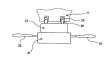
従来から、ステアリングコラムとステアリングホイール11との間には、所定の範囲内でのステアリングホイール11の回転を許容しつつ、これらを電気的に接続するためのロールコネクタ21が設けられている。図1はロールコネクタの取り付け構造を示すハンドル回りの概略図であり、図2は図1の要部拡大断面図である。図1及び図2に示すように、ロールコネクタ21は、ステアリングコラムに固定されたコンビネーションスイッチ31のボディに取り付けられるステータ23と、ステアリングホイール11とともに回転するロータ22とを備えている。
【0003】
ロールコネクタ21のロータ22は、ステアリングホール11側に向けて突出した突出ピン26を有する一方、ステアリングホイール11には、突出ピン26と嵌合する位置に凹部12が形成されている。突出ピン26は、ステアリングホイール11を不図示のステアリングシャフトへ装着すると、この凹部12と嵌合するように寸法構成されている。
【0004】
突出ピン26と凹部12との間に位置ずれが存在する場合、突出ピン26自体はほとんど変形しないので、両者はうまく嵌合することができない。そのために、従来は、嵌合しやすくするために、突出ピン26の外径を小さくか、あるいは凹部12の穴径を突出ピン26の外径より大きくするとともに、この突出ピン26にゴム製キャップ24を被せた結合ピン25の状態で使用されている。ステアリングホイール11がステアリングシャフトに対して固定されると、ロールコネクタ21はステアリングホイール11に対して直接には固定されていないが、ステアリングホイール11が回転するとき、ロータ22はゴム製キャップ24で被われた結合ピン25を介して回転する。このような構成の結合ピン25においては、ゴム製キャップ24がわずかに変形して位置ずれを吸収する弾性吸収体として働き、突出ピン26がほとんど変形しない高剛性体、すなわち心棒として働いている。その結果、結合ピン25は、全体として、ほとんど変形しない高剛性体となっている。
【0005】
【発明が解決しようとする課題】
結合ピン25がゴム製キャップ装着タイプであるロールコネクタ21では、以下のような問題がある。すなわち、ゴム製キャップ24を装着した結合ピン25は、わずかな位置ずれに対してはゴム製キャップ24の変形により位置ずれを吸収することができるが、大きな位置ずれに対しては突出ピン26が心棒として働くために、全体として位置ずれを吸収することができない。したがって、ステアリングホイール11の偏心によってステアリングホイール11上に形成された凹部12の位置が結合ピン25に対して大きくずれていると、ステアリングホイール11の装着あるいは回転操作時に、ロータ22がまともに荷重を受けて突出ピン26をこじて破損させたり、結合ピン25と凹部12との間でがたつき音を発生させたりする。
【0006】
したがって、本発明の解決すべき技術的課題は、ロールコネクタの結合ピンとステアリングホイールの凹部との間における大きな位置ずれを吸収することができる結合構造を提供することである。
【0007】
【課題を解決するための手段および作用・効果】
上記技術的課題を解決するために、本発明によれば以下のロールコネクタが提供される。
【0008】
すなわち、本発明のロールコネクタは、コンビネーションスイッチに固定されるステータと、ステアリングホイールとともに回転するロータとを備え、ロータのステアリングホイール側上面に突設した結合ピンが、ステアリングホイールのロータ側下面に形成された凹部に嵌着されるように構成されたロールコネクタにおいて、結合ピンは、ロータの上面に固着され、位置ずれした凹部に対してゴム状に変形して位置ずれを吸収するとともにステアリングホイールの回転時に結合ピン自身の形状を保持できる弾性を有する材料からなることを特徴とする。
【0009】
上記構成において、ハンドル側の偏心によって凹部の位置ずれがある場合においても、ロールコネクタの結合ピンをステアリングホイールに嵌着した際に、ゴム状に大きく変形して位置ずれを吸収することができる弾性を備える結合ピンが位置ずれを吸収して、こじりや異音等の不具合の発生を防止することができる。そして、ステアリングホイールが回転すると、ロータは、それ自身の形状を保持した結合ピンを介して回転することができる。
【0010】
好ましくは、上記結合ピンは、嵌着、接着、及びネジ止めによって、ロータの上面に固着されている。
【0011】
上記構成によれば、結合ピンをロータの上面に対して簡単に固着できるとともに、ロールコネクタをステアリングコラムに対して回転させる際に、結合ピンを引き抜くような力が働いたとしても、結合ピンが簡単に抜けてしまうことはない。
【0012】
好ましくは、ロータ上面には貫通した嵌合穴を形成するとともに、結合ピンは、凹部に嵌着される突出形状の係止頭部と、係止頭部から延在して嵌合穴と嵌着する係止脚部とからなり、係止脚部は、嵌合穴よりも大径の第1及び第2係止鍔部と、第1係止鍔部と第2係止鍔部との間にあって上記嵌合穴に挿入される径を有する係止凹部とを備え、係止凹部を嵌合穴に嵌合させるとともに、第1係止鍔部と第2係止鍔部とによって嵌合穴を挟着することができる。
【0013】
上記構成によれば、第1係止鍔部と第2係止鍔部との間で嵌合穴を挟着するという簡単な構成で、結合ピンをロールコネクタに対して嵌着することができる。
【0014】
【発明の実施の形態】
以下に、本発明の実施の形態について、図1、図3、及び図4を参照して詳細に説明する。
【0015】
図1は、従来のロールコネクタの取り付け構造を示すハンドル回りの概略図であるが、本発明のロールコネクタ21は、図1のものと大略同じ構成であり、ロールコネクタとステアリングホイールとの結合構造のみが従来例のものと異なっている。図3は、本発明の一実施形態に係る、ロールコネクタのステアリングホイールに対する結合状態を示す断面図であり、図4は、図3において、結合ピンが湾曲しながらステアリングホイールに装着される状態を示す断面図である。
【0016】
図1に示すように、ロールコネクタ21は、ステアリングコラムに固定されたコンビネーションスイッチ31のボディに取り付けられるステータ23と、ステアリングホイール11とともに回転するロータ22とを備えている。ロールコネクタ21は、ステータ23とロータ22とを組み合わせることによって形成されるドーナツ状の空間を有する。その空間内には、渦巻き状に巻かれた不図示のフラットケーブルが、一端をステータ23に、他端をロータ22に固定した状態で収納されている。ステータ21は、ワイパー操作レバー32や方向指示器操作レバー33等が組み込まれたコンビネーションスイッチ31のボディと一体化されている。
【0017】
不図示のステアリングシャフトに固定されるステアリングホイール11の下面には、所定の間隔をおいて配置された凹部12が複数個形成されている。ロータ22は、円形で中央部に不図示の開口が形成された上面22aと、円筒状の周壁22bとを備え、ステータ23に回転可能に保持されている。ロータ22は、その上面22aにおいて、貫通した嵌合穴29を有している。この嵌合穴29は、ステアリングホイール11を不図示のステアリングシャフトに取り付けたときにステアリングホイール11の凹部12に対応するように位置決めされている。
【0018】
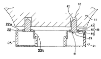
図3に示すように、結合ピン41は、ステアリングホイール11の凹部12に係合する係合頭部42と、係合頭部42から延在する係合脚部46とからなる。係合頭部42は、凹部12より小径であり且つストレートに突出した棒状体である。係合脚部46はロータ22の上面22aに形成された嵌合穴12と係合する係合構造を有している。結合ピン41は、ゴム状に変形して位置ずれを吸収するとともに、ステアリングホイール11が回転する時に結合ピン41自身の形状を保持できる弾性を有する材料からなる。好ましくは、結合ピン41として、ゴム、あるいは熱可塑性エラストマー材料を用いることができる。さらに、好ましくは、結合ピン41として、ポリウレタン系、エチレン・プロピレン系、オレフィン系、ポリエステル系、あるいはシリコン系のエラストマー材料を用いることができる。
【0019】
係合脚部46は、嵌合穴29よりも大径である鍔状の第1及び第2係止鍔部43,44と、第1係止鍔部43と第2係止鍔部44との間にあって嵌合穴29に挿入可能な径を有する係止凹部45とから構成されている。そして、第1及び第2係止鍔部43,44がゴム状に変形することができるので、第2係止鍔部44を把持して変形させながら、第2係止鍔部44の方から嵌合穴29に挿入して、結合ピン41の係止凹部45を嵌合穴29に嵌合させる。第2係止鍔部44を把持することを止めると第2係止鍔部44が元の鍔状に戻って、係合脚部46の係止凹部45がロータ22の嵌合穴29に嵌合するとともに、第1係止鍔部43と第2係止鍔部44とによって嵌合穴29が挟着される。したがって、結合ピン41を引き抜くような力が作用したとしても、結合ピン41が簡単に抜けてしまうことはない。結合ピン41は、このような方法のほかに、例えば、ネジ止めまたは接着等の種々の固定方法によってロータ22の上面22aに対して固定することができる。
【0020】
ロールコネクタ21は、結合ピン41を介する以下に示す方法によって、ステアリングホイール11に対して係合することができる。
【0021】
まず、図3に示すように、ステアリングホイール11の凹部12が、ロータ22の嵌合穴29に嵌着された結合ピン41に対して位置ずれがほとんどない場合について考える。この場合、ステアリングホイール11をステアリングシャフトに対して装着しようとすると、結合ピン41は凹部12に対してスムーズに挿入される。このとき、ロールコネクタ21は結合ピン41と凹部12との嵌合を介してステアリングホイール11に対して間接的に固定される。そして、ステアリングホイール11が回転すると、ロータ22は、略ストレートな形状を保った結合ピン46を介して回転することができる。
【0022】
次に、図4に示すように、ステアリングホイール11の凹部12が、結合ピン41に対して大きく位置ずれしている場合について考える。この場合、ステアリングホイール11をステアリングシャフトに対して装着しようとすると、結合ピン41が図4のように湾曲しながら、凹部12に沿って挿入される。すなわち、結合ピン41は、図4のように湾曲することにより位置ずれを吸収する。そして、ロールコネクタ21は、結合ピン41と凹部12との間の嵌合を介してステアリングホイール11に対して間接的に固定される。ステアリングホイール11が回転すると、こじりや異音等の不具合が発生することなく、ロータ22は、湾曲形状を保った結合ピン46を介して回転することができる。
【図面の簡単な説明】
【図1】 従来のロールコネクタの取り付け構造を示すハンドル回りの概略図である。
【図2】 図1の要部拡大断面図である。
【図3】 本発明の一実施形態に係る、ロールコネクタのステアリングホイールに対する結合状態を示す断面図である。
【図4】 図3において、結合ピンが湾曲しながらステアリングホイールに装着される状態を示す断面図である。
【符号の説明】
11 ステアリングホイール
12 凹部
21 ロールコネクタ
22 ロータ
22a 上面
22b 周壁
23 ステータ
24 ゴムキャップ
29 嵌合穴
31 コンビネーションスイッチ
41 結合ピン
42 係合頭部
43 第1係止鍔部
44 第2係止鍔部
45 係止凹部
46 係合脚部[0001]
BACKGROUND OF THE INVENTION
The present invention relates to a roll connector for electrical connection between a steering column and a steering wheel, and more particularly to a coupling structure between the roll connector and the steering wheel.
[0002]
[Prior art]
Conventionally, a
[0003]
The
[0004]
If there is a misalignment between the projecting
[0005]
[Problems to be solved by the invention]
The
[0006]
Therefore, the technical problem to be solved by the present invention is to provide a coupling structure capable of absorbing a large misalignment between the coupling pin of the roll connector and the recess of the steering wheel.
[0007]
[Means for solving the problems and actions / effects]
In order to solve the above technical problem, the present invention provides the following roll connector.
[0008]
That is, the roll connector according to the present invention includes a stator fixed to the combination switch and a rotor that rotates together with the steering wheel, and a coupling pin that protrudes from the upper surface on the steering wheel side of the rotor is formed on the lower surface on the rotor side of the steering wheel. In the roll connector configured to be fitted into the recessed portion, the coupling pin is fixed to the upper surface of the rotor and is deformed into a rubber shape with respect to the displaced recessed portion to absorb the displacement, and the steering wheel It is characterized by being made of a material having elasticity that can maintain the shape of the coupling pin itself during rotation.
[0009]
In the above configuration, even when the position of the concave portion is displaced due to the eccentricity on the handle side, when the coupling pin of the roll connector is fitted to the steering wheel, it can be deformed greatly into a rubber shape to absorb the displacement. The coupling pin having the structure can absorb misalignment and prevent occurrence of problems such as twisting and abnormal noise. When the steering wheel rotates, the rotor can rotate via a coupling pin that retains its own shape.
[0010]
Preferably, the coupling pin is fixed to the upper surface of the rotor by fitting, bonding, and screwing.
[0011]
According to the above configuration, the coupling pin can be easily fixed to the upper surface of the rotor, and when the roll connector is rotated with respect to the steering column, even if a force for pulling the coupling pin is applied, It won't come out easily.
[0012]
Preferably, a through hole is formed in the upper surface of the rotor, and the coupling pin has a protruding locking head that is fitted in the recess, and extends from the locking head to fit into the fitting hole. The locking leg is composed of first and second locking collars having a diameter larger than that of the fitting hole, and a first locking collar and a second locking collar. A locking recess having a diameter to be inserted into the fitting hole, and the locking recess is fitted into the fitting hole, and is fitted by the first locking collar and the second locking collar. A hole can be pinched.
[0013]
According to the above configuration, the coupling pin can be fitted to the roll connector with a simple configuration in which the fitting hole is sandwiched between the first locking collar and the second locking collar. .
[0014]
DETAILED DESCRIPTION OF THE INVENTION
Hereinafter, embodiments of the present invention will be described in detail with reference to FIGS. 1, 3, and 4.
[0015]
FIG. 1 is a schematic view around a handle showing a conventional roll connector mounting structure. The
[0016]
As shown in FIG. 1, the
[0017]
On the lower surface of the
[0018]
As shown in FIG. 3, the
[0019]
The
[0020]
The
[0021]
First, as shown in FIG. 3, consider a case where the
[0022]
Next, consider a case where the
[Brief description of the drawings]
FIG. 1 is a schematic view around a handle showing a conventional roll connector mounting structure.
FIG. 2 is an enlarged cross-sectional view of a main part of FIG.
FIG. 3 is a cross-sectional view showing a coupling state of a roll connector to a steering wheel according to an embodiment of the present invention.
4 is a cross-sectional view showing a state in which the connecting pin is mounted on the steering wheel while being bent in FIG. 3;
[Explanation of symbols]
Claims (3)
該結合ピン(41)は、ロータ(22)の上面(22a)に固着され、位置ずれした凹部(12)に対してゴム状に変形して位置ずれを吸収するとともにステアリングホイール(11)の回転時に結合ピン(41)自身の形状を保持できる弾性を有する材料からなるとともに中実構造をしていることを特徴とするロールコネクタ。A coupling pin (including a stator (23) fixed to the combination switch (31)) and a rotor (22) that rotates together with the steering wheel (11) projecting from the steering wheel (11) side upper surface of the rotor (22) 41) is a roll connector (21) configured to be fitted into a recess (12) formed on the rotor (22) side lower surface of the steering wheel (11).
The coupling pin (41) is fixed to the upper surface (22a) of the rotor (22), and deforms into a rubber shape with respect to the misaligned recess (12) to absorb the misalignment and rotate the steering wheel (11). A roll connector characterized in that it is made of an elastic material that sometimes holds the shape of the coupling pin (41) itself and has a solid structure .
上記結合ピン(41)は、上記凹部(12)に嵌着される突出形状の係止頭部(42)と、係止頭部(42)から延在して嵌合穴(29)と嵌着する係止脚部(46)とからなり、
該係止脚部(46)は、嵌合穴(29)よりも大径の第1及び第2係止鍔部(43,44)と、第1係止鍔部(43)と第2係止鍔部(44)との間にあって嵌合穴(29)に挿入される径を有する係止凹部(45)とを備え、係止凹部(45)を嵌合穴(29)に嵌合させるとともに、第1係止鍔部(43)と第2係止鍔部(44)とによって嵌合穴(29)を挟着することを特徴とする請求項1記載のロールコネクタ。On the upper surface of the rotor (22), a through hole (29) is formed, and
The coupling pin (41) includes a protruding locking head (42) fitted in the recess (12) and a fitting hole (29) extending from the locking head (42). It consists of a locking leg (46) to wear,
The locking leg (46) includes first and second locking collars (43, 44) having a diameter larger than that of the fitting hole (29), and the first locking collar (43) and the second engagement. A locking recess (45) having a diameter between the locking portion (44) and inserted into the fitting hole (29), and fitting the locking recess (45) into the fitting hole (29). together with the roll connector according to claim 1, characterized in that the sandwiched first holding flange (43) second holding flange and through the fitting hole (29) (44).
Priority Applications (1)
| Application Number | Priority Date | Filing Date | Title |
|---|---|---|---|
| JP19884399A JP4204143B2 (en) | 1999-07-13 | 1999-07-13 | Roll connector |
Applications Claiming Priority (1)
| Application Number | Priority Date | Filing Date | Title |
|---|---|---|---|
| JP19884399A JP4204143B2 (en) | 1999-07-13 | 1999-07-13 | Roll connector |
Publications (2)
| Publication Number | Publication Date |
|---|---|
| JP2001026273A JP2001026273A (en) | 2001-01-30 |
| JP4204143B2 true JP4204143B2 (en) | 2009-01-07 |
Family
ID=16397849
Family Applications (1)
| Application Number | Title | Priority Date | Filing Date |
|---|---|---|---|
| JP19884399A Expired - Fee Related JP4204143B2 (en) | 1999-07-13 | 1999-07-13 | Roll connector |
Country Status (1)
| Country | Link |
|---|---|
| JP (1) | JP4204143B2 (en) |
Families Citing this family (2)
| Publication number | Priority date | Publication date | Assignee | Title |
|---|---|---|---|---|
| JP2006335318A (en) * | 2005-06-06 | 2006-12-14 | Alps Electric Co Ltd | Connection structure of rotary connector to steering angle sensor |
| JP7028638B2 (en) * | 2017-12-28 | 2022-03-02 | 古河電気工業株式会社 | Assembly structure of rotary connector device and rotary connector device |
-
1999
- 1999-07-13 JP JP19884399A patent/JP4204143B2/en not_active Expired - Fee Related
Also Published As
| Publication number | Publication date |
|---|---|
| JP2001026273A (en) | 2001-01-30 |
Similar Documents
| Publication | Publication Date | Title |
|---|---|---|
| EP2597734B1 (en) | Rotary connector device | |
| EP1182726B1 (en) | On-vehicle rod antenna device | |
| US20190203518A1 (en) | Drive device for a window regulator | |
| JP4204143B2 (en) | Roll connector | |
| JP2011134519A (en) | Battery terminal | |
| KR20130043622A (en) | Load torque lock and module having a load torque lock | |
| JPH0332076Y2 (en) | ||
| JPH08180950A (en) | Electrical connection device between steering wheel and steering column | |
| JPH08301126A (en) | Connecting structure for steering wheel and rotary connector | |
| CN116602593A (en) | Cleaning brush and intelligent cleaning equipment | |
| JP2006256492A (en) | Roll connector | |
| EP0482936B2 (en) | Structure for mounting an end support to a rotary connector | |
| JP2003139221A (en) | Gear mounting structure | |
| JP2521697Y2 (en) | Starter | |
| CN104242541B (en) | transmission-driving device | |
| CN214092927U (en) | Connecting structure of rotating shaft belt wheel | |
| US20010007397A1 (en) | Bracket attached to vehicle body | |
| CN218385077U (en) | Gear connection structure and circuit breaker | |
| JPH055674Y2 (en) | ||
| EP4052970A1 (en) | Lock pin assembly | |
| JP4714632B2 (en) | Shift lever device | |
| JP2001098800A (en) | Mounting structure of cylinder lock in key cylinder device | |
| JP3846100B2 (en) | Rotating connector | |
| JP3786228B2 (en) | Joint device between arms in door closer | |
| JPH0831534A (en) | Roll connector device |
Legal Events
| Date | Code | Title | Description |
|---|---|---|---|
| A621 | Written request for application examination |
Free format text: JAPANESE INTERMEDIATE CODE: A621 Effective date: 20060217 |
|
| A977 | Report on retrieval |
Free format text: JAPANESE INTERMEDIATE CODE: A971007 Effective date: 20080215 |
|
| A131 | Notification of reasons for refusal |
Free format text: JAPANESE INTERMEDIATE CODE: A131 Effective date: 20080304 |
|
| A521 | Written amendment |
Free format text: JAPANESE INTERMEDIATE CODE: A523 Effective date: 20080416 |
|
| TRDD | Decision of grant or rejection written | ||
| A01 | Written decision to grant a patent or to grant a registration (utility model) |
Free format text: JAPANESE INTERMEDIATE CODE: A01 Effective date: 20081007 |
|
| A01 | Written decision to grant a patent or to grant a registration (utility model) |
Free format text: JAPANESE INTERMEDIATE CODE: A01 |
|
| A61 | First payment of annual fees (during grant procedure) |
Free format text: JAPANESE INTERMEDIATE CODE: A61 Effective date: 20081014 |
|
| FPAY | Renewal fee payment (event date is renewal date of database) |
Free format text: PAYMENT UNTIL: 20111024 Year of fee payment: 3 |
|
| R150 | Certificate of patent or registration of utility model |
Free format text: JAPANESE INTERMEDIATE CODE: R150 |
|
| FPAY | Renewal fee payment (event date is renewal date of database) |
Free format text: PAYMENT UNTIL: 20121024 Year of fee payment: 4 |
|
| LAPS | Cancellation because of no payment of annual fees |