JP4203962B2 - Joinery - Google Patents
Joinery Download PDFInfo
- Publication number
- JP4203962B2 JP4203962B2 JP2004305512A JP2004305512A JP4203962B2 JP 4203962 B2 JP4203962 B2 JP 4203962B2 JP 2004305512 A JP2004305512 A JP 2004305512A JP 2004305512 A JP2004305512 A JP 2004305512A JP 4203962 B2 JP4203962 B2 JP 4203962B2
- Authority
- JP
- Japan
- Prior art keywords
- door
- shoji
- plane direction
- indoor side
- inward
- Prior art date
- Legal status (The legal status is an assumption and is not a legal conclusion. Google has not performed a legal analysis and makes no representation as to the accuracy of the status listed.)
- Expired - Fee Related
Links
Images


Description
本発明は、引き違いサッシや上げ下げ窓等の枠体に障子を閉じ位置と開き位置に亘って面内方向に開閉自在に装着した建具に関する。 The present invention relates to a fitting in which a shoji is attached to a frame body such as a sliding sash or a raising / lowering window so as to be openable and closable in an in-plane direction over a closed position and an open position.
特許文献1に、枠体に内障子、外障子を、その戸当り框が縦枠材に当接した閉じ位置と縦枠材から離隔した開き位置に亘って面内方向に開閉自在に装着した引き違いサッシが開示されている。
特許文献2に、枠体に可動障子を下枠材に当接した閉じ位置と下枠材から離隔した開き位置に亘って面内方向に開閉自在に装着した上げ下げ窓が開示されている。
In Patent Document 1, the inner frame and the outer frame are attached to the frame body so as to be freely openable and closable in the in-plane direction over the closed position where the door-contact heel contacts the vertical frame material and the open position separated from the vertical frame material. A sliding sash is disclosed.
前述した従来の引き違いサッシにおいては、内障子が閉じ状態の時に戸当り框の室内側部分が一方の縦枠材の内向部の室外側面と重なり合い、外障子が閉じ状態の時に戸当り框の室内側部分が他方の縦枠材の内向部の室外側面と重なり合うようにしてある。
前述した従来の上げ下げ窓においては、可動障子が閉じ状態の時に下框、つまり戸当り框の室内側部分が下枠材の立上り部の室外側面と重なり合うようにしてある。
このように引き違いサッシ、上げ下げ窓等の建具においては、内障子、外障子、可動障子(つまり、障子)の戸当り框の室内側部分を、一方の縦枠、他方の縦枠、下枠(つまり、戸当り枠材)の内向部、立上り部(つまり、内向き突出部)の室外側面に重なり合うことで、障子の戸当り框と枠体の戸当り枠材との間に面内方向の隙間が生じないようにして見栄えを良くしている。
In the above-described conventional sliding sash, the indoor side portion of the door heel overlaps with the outdoor side surface of the inward portion of one vertical frame when the inner shoji is closed, and the door heel is The indoor side portion overlaps the outdoor side surface of the inward portion of the other vertical frame member.
In the conventional raising / lowering window described above, when the movable shoji is in the closed state, the lower side, that is, the indoor side portion of the door-to-door side overlaps the outdoor side surface of the rising portion of the lower frame member.
Thus, in fittings such as sliding sashes, raising and lowering windows, the interior side portion of the door-to-door of the inner sliding door, outer sliding door, and movable sliding door (that is, the sliding door) is connected to one vertical frame, the other vertical frame, the lower frame. In-plane direction between the sliding door of the shoji and the door-to-frame of the frame by overlapping the inward portion of the door-to-door frame material (that is, the door-to-door frame material) The appearance is improved so that there is no gap.
このために、室内から障子を閉じ状態とする際に、その障子の戸当り框の室内側部分と戸当り枠材の内向き突出部との間に指がはさまることがある。
特に、戸当り框に手を掛けて障子を閉じ移動して閉じ状態とする際に、その戸当り框から指がはみ出していると、そのはみ出している指が、前述のように戸当り框の室内側部分と戸当り枠材の内向き突出部との間にはさまれることがある。
For this reason, when the shoji is closed from inside the room, a finger may be caught between the indoor side portion of the door-to-door fence of the shoji and the inward protruding portion of the door-to-door frame material.
In particular, if you put your hand on the door heel and close and move the shoji to the closed state, if the finger protrudes from the door heel, the protruding finger It may be sandwiched between the indoor side portion and the inward protruding portion of the door-to-door frame material.
また、障子は室内と室外の温度差等によって障子全体が反ることがある。
この場合には戸当り框の室内側部分が戸当り枠材の内向き突出部に干渉して障子を確実に閉じることができないことがある。
In addition, the entire shoji may be warped due to a temperature difference between the room and the outside.
In this case, the indoor side portion of the door-to-door fence may interfere with the inward protruding portion of the door-to-door frame member, and the shoji cannot be reliably closed.
本発明の目的は、障子閉じ状態において障子の戸当り框と枠体の戸当り枠材との間に面内方向の隙間が生じることがなく、見栄えが良いと共に、障子の戸当り框の室内側部分と戸当り枠材の内向き突出部との間に指がはさまることがなく、しかも障子全体が反った場合でも障子を確実に閉じることができるようにした建具とすることである。 The object of the present invention is that there is no gap in the in-plane direction between the sliding door of the shoji and the door frame of the frame when the shoji is closed. It is a joinery in which a finger is not pinched between the inner portion and the inward projection of the door-to-door frame member, and the shoji can be reliably closed even when the entire shoji is warped.
本発明は、枠体に障子を面内方向に開閉自在に装着し、その障子の戸当り框を枠体の戸当り枠材に当接して閉じ状態とする建具であって、
前記戸当り枠材は、前記戸当り框よりも面外方向室内側寄りの内向き突出部と、この内向き突部よりも面外方向室外側寄りの内向き片を有し、
前記戸当り框は、室外側部分の面内方向一端部が室内側部分の面内方向一端部よりも前記戸当り枠材寄りで、その室外側部分に引寄せブロックを備え、
障子閉じ状態において前記引寄せブロックが前記内向き片に当接して、前記戸当り枠材の内向き突出部と前記戸当り框の室内側部分との間に面内方向の隙間を形成し、
前記戸当り框の室内側部分に、弾性変形する隙間塞ぎ部材を、前記戸当り框の室内側面と面一に連続して設け、この隙間塞ぎ部材を戸当り枠材の内向き突出部の室外側面と接する或いは重なり合わせることで前記隙間を塞ぐようにしたことを特徴とする建具である。
The present invention is a fitting that attaches a shoji to the frame so that it can be opened and closed in the in-plane direction, and closes the door-to-door fence of the shoji to the door-to-frame material of the frame,
The door-holding frame member has an inward protruding portion closer to the indoor side in the out-of-plane direction than the door-to-door cage, and an inward piece closer to the outer side in the out-of-plane direction than the inward protruding portion,
The one end in the in-plane direction of the outdoor portion is closer to the frame material than the one end in the in-plane direction of the indoor portion, and includes a drawing block in the outdoor portion.
In the closed state of the shoji, the attraction block abuts against the inward piece to form an in-plane gap between the inwardly protruding portion of the door stop frame member and the indoor side portion of the door stop rod,
A gap closing member that is elastically deformed is provided on the indoor side portion of the door- to-door fence continuously with the indoor side surface of the door-to-door fence, and the gap closing member is provided outside the inwardly protruding portion of the door-to-door frame member. The fitting is characterized in that the gap is closed by contacting or overlapping the side surface.
本発明によれば、障子閉じ状態において戸当り枠材の内向き突出部と戸当り框の室内側部分との間の隙間が隙間塞ぎ部材で塞がれるので、障子閉じ状態において障子の戸当り框と枠体の戸当り枠材との間に面内方向の隙間が生じることがなく、見栄えが良い。
また、障子閉じ状態で、その障子の戸当り框の室内側部分と戸当り枠材の内向き突出部との間に隙間があるから、その両者の間に指がはさまれることがない。
また、隙間塞ぎ部材は弾性変形するから、この隙間塞ぎ部材が指に接触すると弾性変形し、指を傷つけることがない。
また、障子全体が反った場合に戸当り框の室内側部分と戸当り枠材の内向き突出部が干渉することがなく、障子を確実に閉じることができる。
また、隙間塞ぎ部材が戸当り框の室内側面と面一に連続することで、内観の見栄えが良い。 According to the present invention, since the gap between the inward protruding portion of the door stopper frame member and the indoor side portion of the door stopper rod is closed by the gap closing member in the closed state of the shoji, the door of the shoji is closed in the closed state of the shoji. There is no gap in the in-plane direction between the bag and the door-to-door frame material of the frame, and the appearance is good.
Further, in the closed state of the shoji, there is a gap between the indoor side portion of the shoji door ridge of the shoji and the inward projecting portion of the door-to-door frame material, so that a finger is not caught between the two.
Further, since the gap closing member is elastically deformed , when the gap closing member comes into contact with the finger, the gap closing member is elastically deformed and the finger is not damaged.
Further, when the shoji as a whole is warped, the indoor side portion of the door-to-door fence and the inward protruding portion of the door-to-door frame member do not interfere with each other, and the shoji can be reliably closed.
Moreover, the gap closing member is continuous with the indoor side surface of the door-to-door fence, so that the appearance is good.
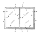
図1は、建具の一種である引き違いサッシの内観図で、枠体10内に内障子20と外障子30が面内方向に開閉自在に装着してある。
前記枠体10は、上枠材11と下枠材12と一方の縦枠材13と他方の縦枠材14を方形状に連結してある。
前記内障子20と外障子30は、上框21,31と下框22,32と召合せ框23,33と戸当り框24,34を方形状に連結し、その内部にガラス25,35が装着してある。
前記内障子20が閉じ状態の時に、その戸当り框24が一方の縦枠材13に当接し、その一方の縦枠材13が内障子20に対する戸当り枠材である。
前記外障子30が閉じ状態の時に、その戸当り框34が他方の縦枠材14に当接し、その他方の縦枠材14が外障子30に対する戸当り枠材である。
FIG. 1 is an interior view of a sliding sash, which is a kind of joinery, in which a
The
The
When the
When the
図2に示すように、各縦枠材13,14は内向き突出部13a,14aを有する。
詳しくは、前記一方の縦枠材13の面外方向室内側部に内向き突出部13aを有し、この内向き突出部13aは内障子20の戸当り框24よりも面外方向室内側寄りである。
前記他方の縦枠材14の面外方向中間部に内向き突出部14aを有し、この内向き突出部14aは外障子30の戸当り框34よりも面外方向室内側寄りである。
As shown in FIG. 2, each of the
Specifically, the one
The other
前記内障子20が閉じ状態の時に、その戸当り框24の室内側部分24aと一方の縦枠材13の内向き突部13aとの間の面内方向の隙間S1は、一般的な人の指の太さよりも大きく、この両者の間に指をはさむことがないようにしてある。
前記戸当り框24の室内側部分24a(好ましくは、面内方向一端面)には、軽い力で弾性変形する隙間塞ぎ部材、例えば軟質材によって薄い板状となった軟質ヒレ26が面内方向で、かつ一方の縦枠材13に向けて設けてあり、内障子20を閉じた時に軟質ヒレ26が内向き突出部13aの室外側面と接する或いは重なり合うようにしてある。
In the state the
On the indoor side portion 24a (preferably, one end surface in the in-plane direction) of the door-to-
このようであるから、軟質ヒレ26で前述の隙間S1を塞ぎ、内障子20の戸当り框24と一方の縦枠材13との間に面内方向の隙間が生じないようにできる。
また、内障子20を閉じた時に軟質ヒレ26と内向き突出部13aとの間に指がはさまれた場合には、その軟質ヒレ26が弾性変形するので、指を傷つけることがない。
また、内障子20全体が反った場合でも、前述の隙間S1があるから戸当り框24の室内側部分24aと一方の縦枠材13の内向き突出部13aが干渉することがなく、しかも軟質ヒレ26が内向き突出部13aと干渉しても弾性変形するので、内障子20を確実に閉じることができる。
Since this be the case, a
In addition, when the finger is sandwiched between the
Further, even when the entire
前記外障子30が閉じ状態の時に、その戸当り框34の室内側部分34aと他方の縦枠材14の内向き突部14aとの間の面内方向の隙間S2は、一般的な人の指の太さよりも大きく、この両者の間に指をはさむことがないようにしてある。
前記戸当り框34の室内側部分34a(好ましくは、面内方向一端面)には、軽い力で弾性変形する隙間塞ぎ部材、例えば軟質材によって薄い板状となった軟質ヒレ36が面内方向で、かつ他方の縦枠材14に向けて設けてあり、外障子30を閉じた時に軟質ヒレ36が内向き突出部14aの室外側面と接する或いは重なり合うようにしてある。
In the state the
On the indoor side portion 34a (preferably, one end surface in the in-plane direction) of the
このようであるから、軟質ヒレ36で前述の隙間S2を塞ぎ、外障子30の戸当り框34と他方の縦枠材14との間に面内方向の隙間が生じないようにできる。
また、外障子30を閉じた時に軟質ヒレ36と内向き突出部14aとの間に指がはさまれた場合には、その軟質ヒレ36が弾性変形するので、指を傷つけることがない。
また、前述と同様に外障子30が反った場合でも、外障子30を確実に閉じることができる。
Since this be the case, a soft fins 36 close the aforementioned gap S 2, can be made so that no in-plane direction of the gap between the
In addition, when a finger is sandwiched between the soft fin 36 and the inward protruding portion 14a when the
In addition, even when the
前述の各戸当り框24,34の好ましい形状について説明する。
前記内・外障子20,30の各戸当り框24,34は、その室外側部分24b,34bの面内方向一端部が室内側部分24a、34aの面内方向一端部よりも面内方向一方に突出して各縦枠材13,14寄りで、内外障子20,30を閉じた時に、その室外側部分24b,34bに設けた引寄せブロック27,37が各縦枠材13,14の内向き片13b,14bに当接し、各室内側部分24a,34aと各内向き突出部13a,14aとの間に大きな面内方向の隙間S1,S2が生じるようにしてある。
前記他方の縦枠材14の内向き突出部14aには気密材14cが室外側に向けて取付けてあり、この気密材14cに軟質ヒレ36が接するようにしてある。
なお、図示はしていないが、前記各軟質ヒレ26,36を各縦枠材13,14に接するようにしても良い。この場合には各軟質ヒレ26,36の先端部を後述するようにほぼU字形状とすることが好ましい。
このようにすれば、各戸当り框24,34と各縦枠材13,14との間の気密性、水密性が向上する。
The preferable shape of the above-mentioned
In each of the
An
Although not shown, the
If it does in this way, the airtightness between each door ledge 24,34 and each
前記各軟質ヒレ26,36は、各戸当り框24,34の室内側面と面一に連続することが好ましい。
このようにすれば、軟質ヒレ26,36が戸当り框24,34の室内側面であるように見えるから、内観の見栄えが良い。
It is preferable that the
In this way, since the
次に、枠体10、内・外障子20,30の具体形状について説明する。
前記一方の縦枠材13は、アルミ押出形材などの金属製の本体1と、この本体1の室内側に取付けた樹脂押出形材などの樹脂製の室内側部材2を備え、この室内側部材2は室外側片2aと内向片2bと室内側片2cでクランク形状で、その室外側片2aが本体1の室内側部に取付けられ、内向片2bが本体1よりも面内方向の内方に突出して内向き突出部13aとしてある。
前記他方の縦枠材14は、アルミ押出形材などの金属製室内側部材3と金属製室外側部材4を断熱材5で連結した断熱形材の本体6と、その金属製室外側部材4の室内寄りと金属製室内側部材3に亘って取付けられた樹脂押出形材などの樹脂製の室内側部材7を備え、この室内側部材7が本体6よりも室内側に突出している。
前記室内側部材7の室外側部分が鉤形に折曲して前述の内向き突出部14aを形成している。
Next, the specific shapes of the
The one
The other
The outdoor side portion of the indoor side member 7 is bent in a bowl shape to form the inward protruding portion 14a.
前記各戸当り框24,34は、アルミ押出形材などの金属製室外側部材28,38と樹脂押出形材などの樹脂製室内側部材29,39で形成されている。
この樹脂製室内側部材29,39の室内側部が前述の室内側部分24a,34aで、その面内方向の一端面に軟質ヒレ26,36が一体的に設けてある。
例えば、樹脂製室内部材29,30を硬質樹脂、軟質ヒレ26,36を軟質樹脂として同時に押出し成形する。
The
The indoor side portions of the resin
For example, the resin
前記上枠材11、下枠材12は、図示を省略するが前述の他方の縦枠材14と同様に、断熱形材の本体と、樹脂製室内側部材を備えている。
前記各上框21,31、下框22,32は、図示を省略するが前述の戸当り框24,34と同様に金属製室外側部材と樹脂製室内側部材を備えている。
The upper frame member 11 and the
Although not shown in the drawings, each of the
前記隙間塞ぎ部材は軟質ヒレ26,36に限ることはなく、例えば図3に示すように軟質樹脂により薄肉板状の鉤形片8,9とし、この鉤形片8,9を樹脂製室内側部材29,39(好ましくは面内方向一端面)に一体的に設けて軽い力で弾性変形するようにしてある。
The gap closing member is not limited to the
次に、一方の縦枠材13と内障子20の戸当り框24の第2の実施の形態を説明する。
図4に示すように、一方の縦枠材13を、アルミ押出形材などの金属製室外側部材40と金属製室内側部材41を断熱材42で連結した断熱形材の本体43と、その金属製室内側部材41に取付けた木製部材44を備えたものとし、その木製部材44が前述の内向き突出部13aを形成する。
戸当り框24は、アルミ押出型材等の金属製室外側部材45と木製室内側部材46を備え、その金属製室外側部材45が前述の室外側部24bで、木製室内側部材46が前述の室内側部分24aである。
この木製室外側部材46の面内方向の端面46aに前述の軟質ヒレ26が取付けられる。例えば、軟質ヒレ26を基片26aと先片26bでL字形状とし、その基片26aを接着、ビス等で前述の端面46aに取付け、先片26bを前述の木製部材44の室外側面44aと接する或いは重なり合わせる。
Next, a second embodiment of the one
As shown in FIG. 4, one
The door-to-
The aforementioned
次に、一方の縦枠材13と内障子20の戸当り框24の第3の実施の形態を説明する。
図5に示すように、一方の縦枠材13を、アルミ押出形材などの金属製室外側部材50と金属製室内側部材51を断熱材52で連結した断熱形材とし、その金属製室内側部材51の室内側部分を鉤形状として前述の内向き突出部13aを形成する。
戸当り框24は、アルミ押出形材等の金属製室外側部材53と金属製室内側部材54を断熱材55で連結した断熱形材とする。
この金属製室内側部材54の面内方向の端面54aに前述の軟質ヒレ26を取付ける取付部、例えばアリ溝56を形成し、このアリ溝56に軟質ヒレ26の基部26cを嵌合して取付け、その軟質ヒレ26の先部26dを内向き突出部13aの室外側面と接する或いは重なり合わせる。
Next, a third embodiment of the one
As shown in FIG. 5, one
The
An attachment portion for attaching the above-described
次に、一方の縦枠材13と内障子20の戸当り框24の第4の実施の形態を説明する。
図6に示すように、一方の縦枠材13を、アルミ押出形材などの金属製の一体形状で、その室内側部が鉤形状となって前述の内向き突出部13aと有するものとする。
戸当り框24をアルミ押出形材などの金属製の一体形状で、その室内側部分24aの面内方向一端部よりも室外側部分24bの面内方向一端部が面内方向一方に突出した形状とする。
この室内側部分24aの面内方向の端面に軟質ヒレ26を、前述の第3の実施の形態と同様に取付ける。
Next, a fourth embodiment of the one
As shown in FIG. 6, it is assumed that one
The door-to-
A
前述の第2・第3・第4の実施の形態は一方の縦枠材13と内障子20の戸当り框24について説明したが、他方の縦枠材14と外障子30の戸当り框34も同様とすることは勿論である。
また、縦枠材13,14の形状、戸当り框24,34の形状は前述した第1・第2・第3・第4の組み合わせに限ることはなく、任意の組み合わせとすることができる。
In the above-described second, third, and fourth embodiments, the one
Moreover, the shape of the
前述の実施の形態は引き違いサッシであるが、片引きサッシの場合には前述の内障子20、外障子30の一方を固定すれば良い。
In the above-described embodiment, the sliding sash is used. However, in the case of the single-sided sash, one of the above-described
10…枠体、13…一方の縦枠材(戸当り枠材)、13a…内向き突出部、13b…内向き片、14…他方の縦枠材、14a…内向き突出部、20…内障子、24…戸当り框、24a…室内側部分、26…軟質ヒレ(隙間塞ぎ部材)、27…引寄せブロック、30…外障子、34…戸当り框、34a…室内側部分、34b…内向き片、36…軟質ヒレ(隙間塞ぎ部材)、37…引寄せブロック。
DESCRIPTION OF
Claims (1)
前記戸当り枠材は、前記戸当り框よりも面外方向室内側寄りの内向き突出部と、この内向き突部よりも面外方向室外側寄りの内向き片を有し、
前記戸当り框は、室外側部分の面内方向一端部が室内側部分の面内方向一端部よりも前記戸当り枠材寄りで、その室外側部分に引寄せブロックを備え、
障子閉じ状態において前記引寄せブロックが前記内向き片に当接して、前記戸当り枠材の内向き突出部と前記戸当り框の室内側部分との間に面内方向の隙間を形成し、
前記戸当り框の室内側部分に、弾性変形する隙間塞ぎ部材を、前記戸当り框の室内側面と面一に連続して設け、この隙間塞ぎ部材を戸当り枠材の内向き突出部の室外側面と接する或いは重なり合わせることで前記隙間を塞ぐようにしたことを特徴とする建具。 It is a fitting that attaches a shoji to the frame so that it can be opened and closed in the in-plane direction, and closes the door-to-door fence of the shoji against the door-to-frame material of the frame,
The door-holding frame member has an inward protruding portion closer to the indoor side in the out-of-plane direction than the door-to-door cage, and an inward piece closer to the outer side in the out-of-plane direction than the inward protruding portion,
The one end in the in-plane direction of the outdoor portion is closer to the frame material than the one end in the in-plane direction of the indoor portion, and includes a drawing block in the outdoor portion.
In the closed state of the shoji, the attraction block abuts against the inward piece to form an in-plane gap between the inwardly protruding portion of the door stop frame member and the indoor side portion of the door stop rod,
A gap closing member that is elastically deformed is provided on the indoor side portion of the door- to-door fence continuously with the indoor side surface of the door-to-door fence, and the gap closing member is provided outside the inwardly protruding portion of the door-to-door frame member. A joinery characterized by closing the gap by contacting or overlapping with a side surface.
Priority Applications (1)
| Application Number | Priority Date | Filing Date | Title |
|---|---|---|---|
| JP2004305512A JP4203962B2 (en) | 2004-10-20 | 2004-10-20 | Joinery |
Applications Claiming Priority (1)
| Application Number | Priority Date | Filing Date | Title |
|---|---|---|---|
| JP2004305512A JP4203962B2 (en) | 2004-10-20 | 2004-10-20 | Joinery |
Publications (2)
| Publication Number | Publication Date |
|---|---|
| JP2006118171A JP2006118171A (en) | 2006-05-11 |
| JP4203962B2 true JP4203962B2 (en) | 2009-01-07 |
Family
ID=36536301
Family Applications (1)
| Application Number | Title | Priority Date | Filing Date |
|---|---|---|---|
| JP2004305512A Expired - Fee Related JP4203962B2 (en) | 2004-10-20 | 2004-10-20 | Joinery |
Country Status (1)
| Country | Link |
|---|---|
| JP (1) | JP4203962B2 (en) |
Families Citing this family (1)
| Publication number | Priority date | Publication date | Assignee | Title |
|---|---|---|---|---|
| JP7337234B2 (en) | 2020-09-01 | 2023-09-01 | 株式会社Lixil | sash window |
-
2004
- 2004-10-20 JP JP2004305512A patent/JP4203962B2/en not_active Expired - Fee Related
Also Published As
| Publication number | Publication date |
|---|---|
| JP2006118171A (en) | 2006-05-11 |
Similar Documents
| Publication | Publication Date | Title |
|---|---|---|
| JP4203962B2 (en) | Joinery | |
| JP2022125214A5 (en) | sash window | |
| KR101234273B1 (en) | Window and door frame | |
| JP2008202269A (en) | Synthetic resin sash | |
| KR102027831B1 (en) | Door and window with wind and water, dust, noise proof function | |
| JP6069108B2 (en) | Joinery | |
| JP5654423B2 (en) | Joinery | |
| JP7130804B2 (en) | sash | |
| JP6836578B2 (en) | sash | |
| JP6895419B2 (en) | sash | |
| JP6995675B2 (en) | Joinery | |
| JP6751800B2 (en) | sash | |
| JP6858212B2 (en) | Insulated sash | |
| JP7361141B2 (en) | sash | |
| JP6919003B2 (en) | sash | |
| JP7041019B2 (en) | Joinery | |
| JP6895420B2 (en) | sash | |
| JP6999476B2 (en) | Joinery | |
| KR102275274B1 (en) | Door and window with wind and water, dust, noise proof function | |
| JP2002242562A (en) | Wire screen device (equipped with suspended piece outside) for outdoor railless sash having flat sill | |
| JP6652435B2 (en) | Joinery | |
| JPS6244053Y2 (en) | ||
| US20070084124A1 (en) | Snap-in insert component for sash windows | |
| JP2021001511A (en) | Fitting | |
| JP4157411B2 (en) | Opening device |
Legal Events
| Date | Code | Title | Description |
|---|---|---|---|
| A621 | Written request for application examination |
Free format text: JAPANESE INTERMEDIATE CODE: A621 Effective date: 20060825 |
|
| A977 | Report on retrieval |
Free format text: JAPANESE INTERMEDIATE CODE: A971007 Effective date: 20080620 |
|
| A131 | Notification of reasons for refusal |
Free format text: JAPANESE INTERMEDIATE CODE: A131 Effective date: 20080709 |
|
| A521 | Written amendment |
Free format text: JAPANESE INTERMEDIATE CODE: A523 Effective date: 20080908 |
|
| TRDD | Decision of grant or rejection written | ||
| A01 | Written decision to grant a patent or to grant a registration (utility model) |
Free format text: JAPANESE INTERMEDIATE CODE: A01 Effective date: 20081008 |
|
| A01 | Written decision to grant a patent or to grant a registration (utility model) |
Free format text: JAPANESE INTERMEDIATE CODE: A01 |
|
| A61 | First payment of annual fees (during grant procedure) |
Free format text: JAPANESE INTERMEDIATE CODE: A61 Effective date: 20081008 |
|
| FPAY | Renewal fee payment (event date is renewal date of database) |
Free format text: PAYMENT UNTIL: 20111024 Year of fee payment: 3 |
|
| R150 | Certificate of patent or registration of utility model |
Free format text: JAPANESE INTERMEDIATE CODE: R150 |
|
| LAPS | Cancellation because of no payment of annual fees |