JP4203279B2 - Attention determination device - Google Patents
Attention determination device Download PDFInfo
- Publication number
- JP4203279B2 JP4203279B2 JP2002218086A JP2002218086A JP4203279B2 JP 4203279 B2 JP4203279 B2 JP 4203279B2 JP 2002218086 A JP2002218086 A JP 2002218086A JP 2002218086 A JP2002218086 A JP 2002218086A JP 4203279 B2 JP4203279 B2 JP 4203279B2
- Authority
- JP
- Japan
- Prior art keywords
- circularity
- line
- sight
- presentation information
- pupil
- Prior art date
- Legal status (The legal status is an assumption and is not a legal conclusion. Google has not performed a legal analysis and makes no representation as to the accuracy of the status listed.)
- Expired - Fee Related
Links
Images


Description
【0001】
【発明の属する技術分野】
本発明は、注目判定装置に関するものである。
【0002】
【従来の技術】
人物の視線や動作など、人間をセンシングして得られる情報と、物体センシングにより構築された周辺環境とから、その人の要望を察知し、その人の意図に適したサービスを提供することが提案されている。これらを実現するためには、人間とその周辺環境をセンシングし、その人が何を見て、どのような動作を行っているかを知ることが重要なこととなる。このとき、視線情報はその人が注目している物、又はその人の意図や状況を推定するのに欠かせない情報の1つである。
【0003】
【発明が解決しようとする課題】
しかしながら、単に視線を検出しても、その人が視線方向にある提示された情報(提示情報)を単に眺めているだけなのか、あるいはその提示情報に注目しているのかの相異を得ることができる方法及びその装置は未だ提案されていない。
【0004】
仮に、提示情報に注目していることが分かる方法及びその装置があるとすると、この方法及び装置によって得られた提示情報に対する人の注目度を分析することが可能となり、その提示情報に対する興味度や、市場性をも分析することが可能となる。
【0005】
本発明の目的は、上記問題点を解決するためになされたものであり、その目的は、提示情報に対する注目度を測ることができる注目判定装置を提供することにある。
【0006】
【課題を解決するための手段】
上記問題点を解決するために、請求項1の発明は、提示情報を所定方向に移動する移動手段と、前記提示情報の移動の期間中の人の視線を検出して視線の移動方向を推測する視線移動方向推測手段と、前記提示情報の所定方向の移動と、推測した前記人の視線の移動方向とが一致しているか否かを判定する判定手段とを備え、前記視線移動方向推測手段は、検出対象者を撮像する撮像手段と、前記撮像手段が撮像した画像データに含まれる顔の目領域から瞳領域を検出する瞳領域検出手段と、前記瞳領域検出手段が検出した瞳領域の形状に対して円形度を算出する円形度算出手段と、前記円形度算出手段が算出した円形度に基づいて視線を検出する視線検出手段と、前記視線検出手段によって検出された視線の移動方向を特定する特定手段とを備えている注目判定装置であることを特徴とする。
【0008】
請求項2の発明では、請求項1において、前記移動手段は、前記提示情報を画像表示する画像表示装置とし、前記画像表示装置における画面内で前記提示情報を移動するようにした。
【0010】
請求項3の発明では、請求項1又は請求項2において、互いに異なる位置に前記撮像手段を複数設け、前記視線検出手段は、各撮像手段から得た画像データに含まれる瞳領域の各円形度を比較することで視線を検出するものとした。
【0011】
請求4の発明では、請求項1乃至請求項3のいずれか1項において、前記円形度算出手段は、前記瞳領域を含む画像データをハフ変換し、ハフ変換の投票空間において、投票数が最大となる投票数最大点を含む第1領域、及び前記投票数最大点を含み前記第1領域よりも大きい第2領域における各投票数から円形度を算出するものとした。
【0012】
請求項5の発明では、請求項1乃至請求項3のいずれか1項において、前記円形度算出手段は、瞳領域の面積及び瞳領域の輪郭線の長さに基づいて円形度を算出するものとした。
【0015】
(作用)
請求項1の発明によれば、撮像手段が撮像した画像データに含まれる顔の目領域から瞳領域が瞳領域検出手段によって検出され、その検出された瞳領域の形状に対して円形度が円形度算出手段により算出される。そして、視線検出手段により、円形度算出手段が算出した円形度に基づいて視線が検出される。特定手段は、視線検出手段によって検出された視線の移動方向を特定する。判定手段は、特定手段によって特定された視線の移動方向が提示情報の移動方向に一致しているか否かを判定する。目領域の中から白目領域と容易に区別して検出可能な瞳領域を用いて視線検出を行うため、従来と異なり、瞳孔を検出可能なまで目領域を拡大して撮像する必要がない。このため、視線検出に瞳孔を用いる場合と比較して検出対象者の頭部位置の影響を受けにくく、人が提示情報に対して注目しているか否かを判定するために好適に視線を検出することができる。
また、請求項2の発明によれば、提示情報は、画像表示装置の画面内で移動される。提示情報を画面に表示する構成では、種々の提示情報を必要に応じて取り替えて表示することができる。
【0016】
請求項3の発明によれば、画像データは、互いに異なる位置に設けられた複数の撮像手段でそれぞれ取得され、各画像データに含まれる瞳領域の各円形度が前記視線検出手段により比較される。そして、この比較結果に基づいて視線が検出される。従って、算出された複数の円形度を比較することで視線を検出しているため、例えば、記憶装置に予め記憶されていた参照データと比較して視線を検出する従来と異なり、検出した瞳領域に対して前記参照データと比較可能な状態にするために較正(キャリブレーション)を行う必要がなく、簡便に視線検出が行われる。
【0017】
請求項4の発明によれば、前記瞳領域を含む画像データはハフ変換され、ハフ変換の投票空間において、投票数が最大となる投票数最大点を含む第1領域、及び前記投票数最大点を含み前記第1領域よりも大きい第2領域における各投票数から円形度算出手段により円形度が算出される。従って、ハフ変換の投票空間への投票数を利用して好適に円形度の算出が実現される。
【0018】
請求項5の発明によれば、円形度は、検出された瞳領域の面積及び瞳領域の輪郭線の長さに基づいて円形度算出手段により算出される。従って、面積及び輪郭線の長さを利用して好適に円形度の算出が実現される。
【0019】
【発明の実施の形態】
以下、本発明の視線検出装置を具体化した第1の実施形態を図1〜図10を参照して説明する。
【0020】
図1(a)に示すように、注目判定装置10は、撮像手段としての複数台(本実施形態では2台)のビデオカメラ11A,11Bと、カメラ用パソコン12A,12Bと、メインパソコン13と、画像表示装置14とを備えている。ビデオカメラ11A,11Bは、CCDカメラである。本実施形態におけるビデオカメラ11A,11B及び画像表示装置14は、全て所定の高さ(例えば、1.15m)に配置されており、画像表示装置14は、ビデオカメラ11A,11Bの設置個所の中間の位置に配設されている。
【0021】
ビデオカメラ11A,11Bにはカメラ用パソコン12A,12Bが接続されている。カメラ用パソコン12A,12Bには、ビデオカメラ11A,11Bで撮影された個々のフレーム(画像データ)が、ビデオレートのカラー画像(640×480)として入力されるようになっている。
【0022】
カメラ用パソコン12A,12Bは、メインパソコン13に接続されており、メインパソコン13は、各カメラ用パソコン12A,12Bとの通信をイーサネット(登録商標)を介したソケット通信で行うようにしている。また、ネットワーク・タイムサーバシステムが用いられており、メインパソコン13がタイムサーバとして設定され、各カメラ用パソコン12A,12Bの時刻がメインパソコン13に合わされるようになっている。又、メインパソコン13は、画像表示装置14に有線接続されている。メインパソコン13は、注目判定装置10の視線検出結果に応じて画像表示装置14における提示情報の表示及び提示情報の移動を制御する。なお、メインパソコン13と画像表示装置14とを有線接続せずに、画像表示装置14における画像表示を無線で制御する態様をとってもよい。
【0023】
(注目判定方法)
以下、第1の実施形態の注目判定方法について説明する。まず、注目判定装置10が行う注目判定の概要を説明する。
【0024】
各ビデオカメラ11A,11Bは、検出対象者Hを撮像し、撮像情報を各カメラ用パソコン12A,12Bに入力する。各カメラ用パソコン12A,12Bは、ビデオカメラ11A,11Bからの画像のキャプチャを行い、画像データから目領域16を検出する。そして、検出された目領域16から、瞳領域17を検出すると共に、瞳領域17の大きさを正規化し、この瞳領域17の形状に対して円形度を算出する。カメラ用パソコン12A,12Bは、その円形度の算出結果をメインパソコン13に送信し、メインパソコン13は、各円形度を比較することで視線を検出する。なお、「円形度」とは、真円に対する近似度合いを示すものであり、真円に近いほど円形度が高いと表現し、円が変形するほど円形度が低いと表現する。例えば、長軸の長さと短軸の長さとの差が大きい楕円になっていくほど、円形度が低くなる。そして、第1の実施形態においては、円形度は、後述する式(6)により算出される評価値Eに比例する。評価値Eが大きければ円形度は高く、評価値が小さければ円形度は低くなる。従って、第1の実施形態において、円形度を算出するというのは、後記する評価値Eを算出することを示す。
【0025】
視線が画像表示装置14の画面に向けられたとき、メインパソコン13は、画像表示装置14の画面に表示されている提示情報Qを移動させる。提示情報Qの移動に伴い、メインパソコン13は、検出される視線の移動方向を推測する。検出される視線の移動方向と提示情報Qの移動方向とが一致する場合、メインパソコン13は、視線が提示情報Qの移動に追従したとの判定を行う。
【0026】
図2及び図3は、注目判定装置10によって遂行される注目判定プログラムを表すフローチャートである。以下、このフローチャートを参照して注目判定装置10による注目判定を説明する。
【0027】
メインパソコン13からカメラ用パソコン12A,12Bへ開始要求信号が送信されると、このフローチャートは開始される。そして、メインパソコン13からカメラ用パソコン12A,12Bへ終了要求信号が送信されるまで、ステップS1の処理が繰り返し行われる。
【0028】
ステップS1において、まず、カメラ用パソコン12A,12Bは、ビデオカメラ11A,11Bからの画像のキャプチャを行うか否かの判定を行う。即ち、本実施形態では、ビデオカメラ11A,11Bからの画像のキャプチャは、所定間隔(例えば0.1秒)毎に行われるようになっており、各カメラ用パソコン12A,12Bは、その時刻か否かを判定する。そして、画像をキャプチャする時刻であると判断した場合(ステップS1がYES)、各カメラ用パソコン12A,12Bは、ビデオカメラ11A,11Bからの画像のキャプチャを行う(ステップS2)。一方、カメラ用パソコン12A,12Bが画像をキャプチャする時刻ではないと判断した場合(ステップS1がNO)、この判定を繰り返す。なお、各カメラ用パソコン12A,12Bの時刻は、メインパソコン13に合わされているため、各カメラ用パソコン12A,12Bは、同時刻に画像のキャプチャを行うようになっている。
【0029】
(顔領域検出)
各カメラ用パソコン12A,12Bは、ビデオカメラ11A,11Bからのフレーム〔画像データ、例えば図4(a)参照〕をキャプチャした後、顔領域検出を行う。顔領域検出は、色情報を用いた公知の肌色基準値による手法を用いている。本実施形態では、均等知覚色空間の1つであるCIE L*u*v 表色系を用いている。
【0030】
まず、入力された画像データから、画像の全領域に亘り、U,V座標値による2次元色ヒストグラムを求め、予め定めた肌色有効範囲内のピーク値(度数が最大の値)を肌色基準値とする。その基準値からの色差に対して公知の判別分析法を適用して閾値を決定し、その閾値に基づいて肌色領域とその他の領域に2値化する〔図4(b)参照〕。本実施形態では、検出対象者Hが一人の場合を想定しているため、複数の肌色領域が検出された場合には、各カメラ用パソコン12A,12Bは最大領域を顔領域15と判定する(ステップS3)。すなわち、抽出された複数の肌色領域にて、画素数(面積)を求め、最大面積Smax の領域を顔領域15とする。なお、以下の説明において、前記U,V座標値は、説明の便宜上UV値又はU値,V値というときもある。
【0031】
ステップS4では、メインパソコン13は、画像表示装置14に対して提示情報の表示を指示し、画像表示装置14は、画面上に提示情報Q〔図1(b)に図示〕を表示する。
【0032】
(視線検出)
次のステップS5〜S9の概要を説明すると、カメラ用パソコン12A,12Bは、顔領域15の中から目領域16を検出する。そして、さらにその目領域16の中から瞳領域17を検出すると共に、その瞳領域17の大きさを正規化する。そして、瞳領域17の形状に対して円形度を算出し、その算出結果をメインパソコン13に送信する。メインパソコン13は、各カメラ用パソコン12A,12Bから受信した各円形度の算出結果を比較して視線を検出する。
【0033】
(目領域検出)
ステップS5において、まず、カメラ用パソコン12A,12Bは、画像データについて肌色基準値を再算出し、肌色領域を抽出する。抽出された肌色領域のうち、最大領域を顔領域15と判定する。
【0034】
カメラ用パソコン12A,12Bは、その顔領域15に基づき、4方向面特徴と色差面特徴を用いたテンプレートマッチング手法により、それぞれ目領域16、並びに口領域を検出する。
【0035】
今回の画像データの1つ前に本フローチャートを用いて処理された画像データにおいて、ステップS5で目領域16及び口領域が検出されていたとする。その場合には、前回の検出結果に基づいて、今回得られた顔領域15を所定領域削除し、顔領域15が前記所定領域分狭められた探索範囲として設定されるようになっている。そして、今回の画像データに関しては、前記探索範囲が用いられ、テンプレートマッチング手法により目領域16及び口領域の検出が行われる。なお、テンプレートマッチングを行った結果、前記探索範囲に対して目領域16及び口領域が検出されなかった場合は、再度、顔領域15に対して目領域16及び口領域の検出が行われるようになっている。
【0036】
ここで、前記テンプレートマッチング手法について説明する。
この手法は、得られた画像データから、前述した4方向面特徴抽出にて4方向面特徴(方向面)、及びU,V座標値による色差面特徴を抽出し、肌色領域抽出で得られた肌色領域(顔領域15)又は探索範囲に対して、右目、左目、口の各テンプレートを用いて類似度を計算する。
【0037】
なお、前記色差面特徴は、肌色基準値からのU値の差、及びV値の差を示すものである。また、前記テンプレートとは、予め、右目、左目、口の画像を複数枚用意し、4方向面特徴及び色差面特徴を抽出した画像データを、所定比率で縮小し、横幅を所定ピクセル(例えば32ピクセル)に揃え、大きさの正規化を行ったものである。そして、4方向面特徴に関しては、エッジ方向情報を4方向に分解し、さらに、4方向面特徴及び色差面特徴に対してガウシャンフィルタで平滑化し、各画像データを8×8の解像度に変換したものである。このテンプレートは、記憶装置(図示しない)に記憶されている。
【0038】
そして、テンプレートTと画像データ(入力画像)Iとの4方向面特徴の類似度aを以下の式(1)で算出し、色差面特徴の類似度bを以下の式(2)で算出する。
【0039】
【数1】

【数2】
【0041】
次いで、これらの式(1),(2)で算出した、各類似度a,bに基づいて、以下の式(3)により、最終的な類似度kを算出する。
k=Wa ×a+Wb ×b ・・・(3)
式(3)中、Wa ,Wb は、重み付けとして、各類似度a,bに掛け合わせられる所定の定数であり、Wa +Wb =1を満たしている。本実施形態では、Wa =Wb =0.5としている。
【0042】
類似度kの算出結果を基に、類似度kが予め設定された閾値以上の箇所を目の候補領域とする。そして、入力画像(画像データ)には、左上座標が予め付与されており、その座標に基づき、目、口の位置関係が把握できる。従って、その座標に基づいて、例えば、目は口より上にある、右目と左目の配置等、目、口の大まかな位置関係(座標位置)を満たし、最も類似度kの高い組み合わせを目領域16並びに口領域として決定する。この結果、顔領域15の中で目領域16が検出される。
【0043】
(瞳領域検出)
次にステップS6において、検出された目領域16からカメラ用パソコン12A,12Bは、瞳領域17の検出を行う。本実施形態では、ステップS5にて検出された目領域16のうち何れか一方(例えば右目)の目領域16について、以下に説明する瞳領域検出を行う。
【0044】
まず、目領域画像の彩度値ヒストグラムを作成して、公知の判別分析法を適用し、顔領域15を目領域16と肌領域(顔領域の目領域16以外の領域)とに分離する。一般的に、肌領域の彩度は高く、目領域16の彩度は低い。このため、この分離処理はその特性を利用している。次いで、前記目領域画像の輝度ヒストグラムを作成して、公知の判別分析法を適用し、分離された目領域16を、瞳領域17と白目領域18とに分割する。このとき、白目領域18と瞳領域17の彩度の違いは明らかであるため、例えば瞳領域17を瞳孔と虹彩とに分割する場合と比較して、拡大された画像データでなくても簡便に分割処理ができる。
【0045】
その後、瞳領域17の検出結果を基に、瞳領域17を縮小又は拡大し、所定の大きさに正規化する。そして、瞳領域17に対して円形状の補完を行う。この際、前述したように、彩度値ヒストグラム及び輝度ヒストグラムにそれぞれ判別分析法を適用して分割することで得られた瞳領域17内には、図5(a)に示すように、瞼による陰影171の存在が考えられる。このとき、通常、画像の濃淡値を8ビットで表した場合、濃淡値0が黒、濃淡値256が白となる。そこで、領域分割結果における濃淡値0(黒色)の領域に対して、図5(b)に示すような水平射影ヒストグラムを作成する。そして、同ヒストグラムにおいて縦軸方向〔図5(b)において上下方向〕の上部に示されるように、極端なピークをもつ部分を予め設定された閾値に基づいて削除する。つまり、瞼による陰影171の部分は、該ヒストグラム上でピークとして現れ、それを削除することで、図5(c)に示すような、瞳領域17のみが抽出される。
【0046】
(円形度算出)
次に、ステップS7において、カメラ用パソコン12A,12Bは、検出された瞳領域17に対して円のハフ変換を行い、このハフ変換で用いられるパラメータ空間における投票数によって円形度の算出を行う。
【0047】
まず、目領域16に対して、白目領域18と検出された瞳領域17との濃淡の違いを利用して、Prewitt オペレータを用い、図5(d)に示すような瞳領域17のエッジ画像を生成することで、エッジ(輪郭)172を抽出する。その後、そのエッジ172を構成する点(以下「エッジ点」という)群に対して公知の円のハフ変換を行う。
【0048】
ここで、円のハフ変換について図6(a)及び図6(b)を用いて簡単に説明する。
図6(a)に示すようなあるx−y平面において、円は次の方程式(4)で表される。
【0049】
(x−a)2+(y−b)2=r2・・・(4)
x−y平面上の1つの円は、円の中心(a,b)及び半径rに関する(a,b,r)パラメータ空間(以下、単に「パラメータ空間」という)では1点で表現される。円のハフ変換は、x−y平面を円の特徴を示す3次元のパラメータ空間に変換する。そして、この円のハフ変換は、式(4)を変換した次式(5)で実現する。
【0050】
b=±√{r2−(x−a)2}+y ・・・(5)
この式(5)を利用して、x−y平面における円上の任意の点(x0,y0)をハフ変換すると、パラメータ空間では、b=±√{r2−(x0−a)2}+y0上に乗った画素〔点(a,b,r)〕に投票がなされる。すると、パラメータ空間において、投票結果である点群は、(x0,y0)を通る全ての円の集まりで表現される。例えば、図6(a)に示したx−y平面上の3点e(x1,y1)、f(x2,y2)、g(x3,y3)を式(5)でパラメータ空間に投射すると、それぞれの半径の値rに対するa−b平面について、各点e,f,gが図6(b)に示すような1つずつの円に変換される。なお、図6(b)は、r=r0におけるa−b平面を示している。このハフ変換によって得られた円をハフ曲線という。
【0051】
前記ハフ曲線は、パラメータ空間において互いに交じり合うため、交点が複数生じる。そして、交わるハフ曲線の数(即ち、投票数)が最大の交点を見つけることにより、x−y平面の円の中心座標と半径が検出可能になっている。なお、図6(b)においては、交点(a0,b0,r0)において、3つのハフ曲線が交わり、交点に対する投票数は3となっている。それに対して、それ以外の点では投票数が2以下であるため、x−y平面の円の中心座標は(a0,b0)となり、半径はr0と決定される。
【0052】
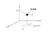
さて、瞳領域17のエッジ画像におけるエッジ点群には左上座標(x,y)が付与される。そして、前記円のハフ変換を行い、図5(d)に示すようなエッジ点群が付されたx−y平面を、図7に示すような瞳領域17の中心座標(a1,b1)と半径r1を示すための3次元パラメータ空間へ変換する。そして、x−y平面における各エッジ点が、パラメータ空間において、式(5)を満たす所定の画素〔点(a,b,r)〕に投票する。そして、図形空間におけるエッジ172をくまなく走査して、パラメータ空間において、最大投票数を得た点が瞳中心点Cとなる。前記瞳中心点Cが投票数最大点に相当し、パラメータ空間が投票空間に相当する。なお、図7のa軸及びb軸の値は中心座標を示し、r軸の値は半径を示す。また、瞳領域17の半径rの範囲(rmin 〜rmax )は予めカメラ用パソコン12A,12Bの記憶装置(図示しない)に記憶されており、ハフ変換の際には、その範囲(rmin 〜rmax )内の所定の画素〔点(a,b,r)〕に投票がなされる。
【0053】
ところで、図8に示すように、例えば検出対象者Hがビデオカメラ11Aを真正面から直視しているとき、ビデオカメラ11Aにて撮像された画像における瞳(瞳領域17)の形状は、図9(a)に示すように真円になる。また、このとき、ビデオカメラ11Aの近傍に位置するビデオカメラ11Bの方向から検出対象者Hを見ると、同検出対象者Hは他の方向を見ていることになる。そのため、ビデオカメラ11Bにて撮像された画像における瞳(瞳領域17)の形状は、図9(b)に示すように、楕円のような変形した円になる。
【0054】
つまり、検出対象者Hの視線が向けられていれば、撮像した瞳(瞳領域17)の形状は、真円若しくは真円に近い形を示すのである。その一方で、視線が外れていれば、外れるほど撮像した瞳(瞳領域17)の形状は、短軸の長さと長軸の長さとの差が広がった楕円を示すのである。本実施形態においては、ビデオカメラ11A,11Bは全て同じ高さに配置されているため、図9(b)に示す視線が外れた状態の瞳(瞳領域17)の形状は縦長の楕円となる。従って、複数のビデオカメラ11A,11Bで撮像した瞳(瞳領域17)の形状を比較して、ある瞳(瞳領域17)の形状がより真円に近いということは、検出対象者Hがそのビデオカメラ11Aへ視線を向けていることを示す。
【0055】
一方、ハフ変換を行った際のパラメータ空間での投票数において、x−y平面たるエッジ画像の瞳領域17(エッジ172)の形状が真円に近いほど、図10(a)に示すように瞳中心点Cとされる点(a1,b1,r1)に投票数が集中し、その周辺の投票数との差が大きくなるという特性がある。また、エッジ画像の瞳領域17(エッジ172)の形状が楕円形になった場合、その長軸の長さと短軸の長さとが異なるほど投票数がばらつき、図10(b)に示すように、瞳中心点Cとされる点(a1,b1,r1)の投票数とその周辺の投票数との差が開きにくくなるという特性がある。なお、図10(a),(b)に示す3次元空間は、中心座標(a1,b1)を示すためのa−b平面に、投票数を示すv軸が直交した三次元空間を示し、図7に示すパラメータ空間とは異なる。また、図10(a),(b)は、共に半径r=r1のa−b平面における投票数を示している。
【0056】
以上の結果により、パラメータ空間において決定された瞳中心点Cの投票数Vcと、この瞳中心点Cを中心とした比較領域P〔図9(a),(b)に図示〕内の投票数Vrとから、次式(6)により円形度を示す評価値Eを算出する。なお、以下においては、瞳中心点Cの投票数Vcを「中心投票数」といい、瞳中心点Cを中心とした比較領域P〔図9(a),(b)に図示〕内の投票数Vrを「領域投票数」ということにする。
【0057】
E=k×Vc/Vr ・・・(6)
式(6)中、kは、重み付けとして掛け合わせられる所定の定数である。また、本実施形態において、比較領域Pとは、瞳中心点Cにおける中心座標(a1,b1)を中心として5×5画素の範囲を示す。領域投票数Vrは、図10(a),(b)に示すようなr=r1における投票数だけではなく、比較領域Pに含まれたそれぞれのrにおける投票数も含む。瞳中心点Cが第1領域に相当し、比較領域Pが第2領域に相当する。
【0058】
そして、前述したように、瞳領域17が真円に近くなるほど、瞳中心点Cに投票数が集中するため、式(6)においては、分子の中心投票数Vcが大きくなり、評価値Eも大きくなる。また、瞳領域17が真円から離れるほど投票数がばらつくため、式(6)においては、分子の中心投票数Vcが小さくなる一方で、分母の領域投票数Vrが大きくなり、評価値Eが小さくなる。この結果、評価値Eが大きくなれば円形度が高くなり、評価値Eが小さくなれば円形度は低くなる。
【0059】
カメラ用パソコン12A,12Bは、前記のようにして算出された円形度(評価値E)の結果をメインパソコン13に送信する。なお、各カメラ用パソコン12A,12Bの時刻は、メインパソコン13に合わされているため、各カメラ用パソコン12A,12Bから送信される円形度(評価値E)の算出結果は、それぞれ同時刻にキャプチャした画像データから算出されたものになっている。
【0060】
(視線検出)
ステップS8において、メインパソコン13は、カメラ用パソコン12Aから受信した評価値Eaと、カメラ用パソコン12Bから受信した評価値Ebとの差を演算する。評価値Eaと評価値Ebとの差|Ea−Eb|が予め設定された閾値Δよりも小さい場合、メインパソコン13は、視線が画像表示装置14の画面上の提示情報Qに向けられているとの判定を行う(ステップS9がYES)。評価値Eaと評価値Ebとの差|Ea−Eb|が閾値Δよりも大きい場合、メインパソコン13は、視線が画像表示装置14の画面上の提示情報Qに向けられていないとの判定を行う(ステップS9がNO)。
【0061】
視線が画像表示装置14の画面上の提示情報Qに向けられていないとの判定が行われた場合、メインパソコン13は、この結果を記憶する(ステップS20)。
【0062】
視線が画像表示装置14の画面上の提示情報Qに向けられているとの判定が行われた場合、メインパソコン13は、提示情報Qを右側へ(ビデオカメラ11A側からビデオカメラ11B側へ)、又は左側へ(ビデオカメラ11B側からビデオカメラ11A側へ)の移動を画像表示装置14に指示する。画像表示装置14は、この指示に基づいて提示情報Qを右側へ、又は左側へ向けて移動させる(ステップS10)。
【0063】
提示情報Qが移動開始した後、ステップS2,S3と同じ画像収集(ステップS12)及び顔領域検出(ステップS13)が遂行される。次に、ステップS5〜S7と同じ目領域検出(ステップS14)、瞳領域検出(ステップS15)及び円形度算出(ステップS16)が遂行される。ステップS16の遂行後、メインパソコン13は、カメラ用パソコン12Aから受信した評価値Eaと、カメラ用パソコン12Bから受信した評価値Ebとの大小関係を比較すると共に、この比較結果を記憶する(ステップS17)。提示情報Qの移動期間t0は、例えば3秒というように予め設定されている。メインパソコン13は、提示情報Qの移動開始時からの経過時間が移動期間t0に達したか否かを判断している(ステップS18)。ビデオカメラ11A,11Bからの画像のキャプチャは、所定間隔(0.1秒)毎に行われており、ステップS17における比較は、提示情報Qの移動開始時からの経過時間が移動期間t0に達するまでの間、所定間隔(0.1秒)毎に行われている。従って、評価値Eaと評価値Ebとの大小関係の比較結果〔差(Ea−Eb)〕の記憶は、0.1秒毎に3秒/0.1秒=30回分だけ行われる。
【0064】
提示情報Qの移動開始時からの経過時間が移動期間t0に達すると、メインパソコン13は、記憶した比較結果に基づいて、視線が提示情報Qの移動に追従したか否かの判定を行う(ステップS19)。
【0065】
メインパソコン13が提示情報Qの左側への移動を指示したとする。つまり、提示情報Qがビデオカメラ11B側からビデオカメラ11A側へ移動したとする。この場合、視線が提示情報Qの移動に追従したか否かの判定基準は、例えば以下のようである。
【0066】
〈1〉評価値Eaと評価値Ebとの差(Ea−Eb)が前回の差(Ea’−Eb’)よりも大きい場合が少なくともz回(zは、例えば10といった複数)ある。
【0067】
なお、前回の差(Ea’−Eb’)とは、差(Ea−Eb)を得たときよりも0.1秒前に得られた差(Ea’−Eb’)のことである。
メインパソコン13が提示情報Qの右側への移動を指示したとする。つまり、提示情報Qがビデオカメラ11A側からビデオカメラ11B側へ移動したとする。この場合、視線が提示情報Qの移動に追従したか否かの判定基準は、例えば以下のようである。
【0068】
〈2〉評価値Eaと評価値Ebとの差(Ea−Eb)が前回の差(Ea’−Eb’)よりも小さい場合が少なくともz回(zは、例えば10といった複数)ある。
【0069】
判定基準〈1〉が満たされるか、あるいは判定基準〈2〉が満たされた場合、メインパソコン13は、視線の移動方向を特定すると共に、視線が提示情報Qの移動に追従したとの判定を行う。判定基準〈1〉及び判定基準〈2〉がいずれも満たされない場合、メインパソコン13は、視線が提示情報Qの移動に追従しなかったとの判定を行う。
【0070】
メインパソコン13は、判定結果を記憶する(ステップS20)。
第1の実施形態では、カメラ用パソコン12A,12Bは、撮像手段が撮像した画像データに含まれる顔の目領域から瞳領域を検出する瞳領域検出手段に相当する。又、カメラ用パソコン12A,12Bは、瞳領域検出手段が検出した瞳領域の形状に対して円形度を算出する円形度算出手段に相当する。メインパソコン13は、円形度算出手段が算出した円形度に基づいて視線を検出する視線検出手段に相当する。又、メインパソコン13は、視線検出手段によって検出された視線の移動方向を特定する特定手段、及び提示情報の所定方向の移動と推測した人の視線の移動方向とが一致しているか否かを判定する判定手段に相当する。
【0071】
第1の実施形態によれば、以下のような効果を得ることができる。
(1)提示情報Qが所定方向(右側又は左側)に移動するときに人の視線が検出される。この視線検出に基づいて視線の移動方向が推測される。この推測された視線の移動方向と、提示情報Qの移動方向とが一致しているか否かの判定が行われる。本実施形態では、判定基準〈1〉又は判定基準〈2〉が満たされていれば、視線の移動方向と提示情報Qの移動方向とが一致しているとの判定が行われる。人の視線が静止している提示情報に向けられている場合には、人が視線方向にある提示情報を単に眺めているだけなのか、あるいはその提示情報に注目しているのかが判然としない。しかし、視線の移動方向と提示情報Qの移動方向とが一致しているとの判定が行われた場合には、人が提示情報Qに注目しているものと特定することができる。
【0072】
視線が提示情報Qの移動に追従したとの判定や、視線が提示情報Qの移動に追従しなかったとの判定は、提示情報Qに対する人の注目度を分析することを可能にし、その提示情報に対する興味度や、市場性をも分析することが可能となる。
【0073】
(2)1台のビデオカメラのみによって得られた評価値Eから追従判定を行う場合、提示情報Qの移動中に1台のビデオカメラのみによって得られた今回の評価値と前回の評価値との差を評価して追従判定を行うことになる。本実施形態では、提示情報Qの移動中に2台のビデオカメラ11A,11Bによって得られた評価値Ea,Ebの差を評価して追従判定を行っている。つまり、評価値Ea,Ebの差と前回の評価値Ea,Ebの差との大小関係を把握することによって追従判定を行っている。提示情報Qが左側に移動するとすると、評価値Eaは、視線が提示情報Qの移動に追従するにつれて大きくなってゆくが、評価値Ebは、視線が提示情報Qの移動に追従するにつれて小さくなってゆく。
【0074】
図9(a)の鎖線で示す瞳領域17aは、画像表示装置14の画面上の移動前の提示情報Qを見ているときにビデオカメラ11Aで撮像されたものである。図9(a)の鎖線で示す瞳領域17bは、画像表示装置14の画面上の移動前の提示情報Qを見ているときにビデオカメラ11Bで撮像されたものである。そこで、図9(a),(b)の鎖線で示す瞳領域17a,17bは、ビデオカメラ11A,11Bによって前回得られたものとする。図9(a),(b)の実線で示す瞳領域17,17は、ビデオカメラ11A,11Bによって今回得られたものとする。そして、1台のビデオカメラ11Aのみによって得られた前回の評価値E〔図9(a)の鎖線で示す瞳領域17の大きさに対応〕と今回の評価値E〔図9(a)の実線で示す瞳領域17の大きさに対応〕との差をΔ1(>0)とする。又、1台のビデオカメラ11Bのみによって得られた前回の評価値E〔図9(b)の鎖線で示す瞳領域17の大きさに対応〕と今回の評価値E〔図9(b)の実線で示す瞳領域17の大きさに対応〕との差をΔ2(>0)とする。
【0075】
そうすると、2台のビデオカメラ11A,11Bによって得られた前回の評価値Ea,Ebの差は、零であるが、2台のビデオカメラ11A,11Bによって得られた今回の評価値Ea,Ebの差は、(Δ1+Δ2)である。従って、前回の評価値Ea,Ebの差と、今回の評価値Ea,Ebの差との差は、(Δ1+Δ2)である。つまり、2台のビデオカメラによって得られた今回の評価値Ea,Ebの差と前回の評価値Ea,Ebの差との違いは、1台のビデオカメラのみによって得られた評価値と前回の評価値との差よりも大きい。従って、2台のビデオカメラ11A,11Bを用いた注目判定の精度は、1台のビデオカメラを用いた注目判定の精度よりも高くなる。つまり、2台のビデオカメラ11A,11Bを用いた注目判定方法は、1台のビデオカメラを用いた注目判定方法よりも正確な注目判定を行うことができる。
【0076】
(3)提示情報Qは、画像表示装置14の画面内で移動される。提示情報Qを画面に表示する構成では、種々の提示情報を必要に応じて簡単に取り替えて表示することができ、多数の提示情報に対する人の注目度を分析することが容易である。
【0077】
(4)本実施形態では、カメラ用パソコン12A,12Bは、ビデオカメラ11A,11Bにより撮像した画像データに含まれる目領域16から瞳領域17を検出し、この瞳領域17の形状に対して円形度を算出する。そして、カメラ用パソコン12A,12Bは、その算出結果をメインパソコン13に送信し、メインパソコン13は、その円形度に基づいて視線を検出する。従来と異なり、視線検出に瞳孔を利用せず、瞳孔よりも大きく、目領域16の中から白目領域18と容易に区別できる瞳領域17の円形度に基づいて視線検出を行ったため、瞳孔を検出可能な位まで目領域16を拡大して撮像する必要がない。そのため、ビデオカメラ11A,11Bにて検出対象者Hを捕捉可能な範囲が広がる。従って、検出対象者Hの位置に影響されることなく、人が提示情報Qに対して注目しているか否かを判定するために好適に視線を検出することができる。
【0078】
(5)本実施形態では、視線検出空間内に複数のビデオカメラ11A,11Bを互いに異なる位置に配置し、各ビデオカメラ11A,11Bでそれぞれ同時に検出した各瞳領域17の円形度をメインパソコン13により比較して視線検出を向行っている。従って、従来と異なり、カメラ用パソコン12A,12Bで算出された円形度(評価値E)を予め記憶した参照データと比較しないため、検出した瞳領域17に対して較正(キャリブレーション)を行う必要がなく、簡便に視線検出を行うことができる。
【0079】
(6)本実施形態では、2つのビデオカメラ11A,11Bしか用いていないが、設置するビデオカメラは、カメラ用パソコンを介してメインパソコン13に接続するだけで容易に追加できる。このため、視線検出の精度向上及び検出領域の拡張を容易に図ることができる。
【0080】
(7)円形度の適正な把握は、提示情報Qに対する人の注目度を判定する上で重要である。本実施形態では、瞳領域17のエッジ画像をハフ変換し、変換先のパラメータ空間において、投票数が最大となる瞳中心点Cと、瞳中心点Cを含む比較領域Pにおける各投票数から円形度を示す評価値Eを算出した。従って、パラメータ空間における投票数を利用して好適に円形度の算出が実現できる。
【0081】
(8)本実施形態では、メインパソコン13において、2つのカメラ用パソコン12A,12Bから受信した評価値Eが所定の許容範囲内(閾値Δ以下)で等しいと判断した場合は、両ビデオカメラ11A,11Bのほぼ中央を見ているものと判断する。このときには人の視線が提示情報Qに向けられており、この状態から提示情報Qを右あるいは左のどちらに移動しても、追従判定を行うことができる。
【0082】
本発明では、図11(a),(b)に示すように、ビデオカメラ11を1台だけ用いた第2の実施形態も可能である。第1の実施形態と同じ構成部には同じ符号が用いてある。
【0083】
画像表示装置14は、上から見てビデオカメラ11の光軸よりも左側に設置されている。カメラ用パソコン12は、第1の実施形態のカメラ用パソコン12A,12Bと同じ役割を果たす。カメラ用パソコン12A,12Bは、算出された円形度(評価値E)の結果をメインパソコン13Cに送信する。メインパソコン13Cは、カメラ用パソコン12から受信した評価値Eに基づいて、視線が画像表示装置14の画面上の提示情報に向けられているか否かの判定を行う。評価値Eが最大の場合、メインパソコン13Cは、視線が提示情報に向けられているとの判定を行う。この判定後、提示情報を右へ移動し、これに伴って視線が右へ移動した場合には、視線が提示情報の移動に追従したとの判定を行う。メインパソコン13Cは、提示情報の移動中に1台のビデオカメラ11のみによって得られた今回の評価値が前回の評価値よりも大きい場合には、視線が右へ移動したとの特定を行う。メインパソコン13Cは、提示情報の移動中に1台のビデオカメラ11のみによって得られた今回の評価値が前回の評価値よりも小さい場合には、視線が左へ移動したとの特定を行う。
【0084】
第2の実施形態においても、人が提示情報に注目しているのか否かを特定することができる。
本発明では以下のような実施形態も可能である。
【0085】
・ビデオカメラ、視線検出用光源、受光センサ、記憶装置、及び判定制御装置等を備えた視線検出装置を本発明の注目判定装置の視線移動方向推測手段の一部として用いること。記憶装置には、視線検出判定を行うための参照データが予め記憶されている。
【0086】
注目判定に用いる前記視線検出装置では、ビデオカメラによって検出対象者を拡大して撮像し、拡大した目領域の画像データから瞳孔を検出する。このとき、前記参照データとの比較処理に利用可能な状態にするために、検出した瞳孔に対して較正(キャリブレーション)を行う。また、前記視線検出用光源から検出対象者に赤外光を照射して、同赤外光を検出対象者の眼部に照射し、前記受光センサにより眼部(瞳孔と角膜)にて反射する反射光を受光する。瞳孔と反射光との位置関係と、前記参照データとが判定制御装置において比較され、視線が検出される。
【0087】
この場合にも、人が提示情報に注目しているのか否かを把握することができる。
・第1の実施形態において、提示情報を左側(又は右側)へ移動して止めた後、右側(左側)へ移動し、この提示情報の移動の間における視線の移動方向を検出すること。この場合、提示情報の左側への移動に視線の移動が追従し、かつ提示情報の右側への移動に視線の移動が追従した場合には、視線が提示情報Qの移動に追従したとの判定を行うようにすればよい。このようにすれば、人が提示情報に注目しているのか否かを一層確実に把握することができる。
【0088】
・第1の実施形態において、顔領域の検出を省略し、目領域を拡大して撮像して視線検出を行うようにすること。
・第1の実施形態では、カメラ用パソコン12A,12Bにおける円形度(即ち、評価値E)の算出に、瞳領域17のエッジ画像をハフ変換する際におけるパラメータ空間の投票数を利用したが、以下の方法で円形度を算出してもよい。すなわち、ステップS6,S15において検出され、円形状の補完が行われた瞳領域17全体の画素数から面積Sを求め、瞳領域17のエッジ画像からエッジ172の画素数を数えることでエッジ172(即ち、輪郭線)の長さLを求める。そして、各カメラ用パソコン12A,12Bでは、次式(7)から円形度を示す評価値Rateを算出する。
【0089】
Rate=4πS/L2 ・・・(7)
これによれば、円形度は式(7)により算出される評価値Rateに基づいて決定され、評価値Rateが1に近づくほど円形度は高く、1から離れるほど円形度は低くなる。従って、この別例においては、円形度を算出するというのは評価値Rateを算出することを示す。このようにしても、瞳領域17の面積S及びエッジ172の長さLを利用して好適に円形度の算出が実現できる。
【0090】
・第1の実施形態では、式(6)における分子の中心投票数Vcは、投票数が最大である瞳中心点Cのみの投票数であった。これに代えて、例えば、瞳中心点Cとその隣の点を合せた領域の投票数の合計を中心投票数Vcとする等、少なくとも比較領域Pよりも狭い領域の投票数であれば、中心投票数Vcとしてもよい。この場合、瞳中心点Cとその隣の点を合せた領域が第1領域に相当し、比較領域Pが第2領域に相当する。
【0091】
・第1の実施形態では、ステップS8,S15における瞳領域検出を、ステップS5,S14において検出された目領域16のうち何れか一方の目領域16について行ったが、右・左の両方の目領域16に対して行ってもよい。この場合、各瞳領域17から算出された円形度(評価値E)の平均値が算出され、その値が、各画像データの円形度とされ、比較される。このようにすれば、片目について円形度を算出する場合と比較して、高精度に視線検出を行うことができ、注目判定の精度が一層向上する。
【0092】
・第1の実施形態では、複数台のビデオカメラ11A,11Bを視線検出空間内に設け、各ビデオカメラ11A,11Bのカメラ用パソコン12A,12Bにて算出された円形度(評価値E)をメインパソコン13が比較することで、視線を検出した。これに代えて、撮像された画像データに基づく各円形度同士の比較ではなく、予めメインパソコン13に記憶した閾値との比較で視線を検出してもよい。すなわち、各カメラ用パソコン12A,12Bから送信された評価値Eと前記閾値との比較を行って視線検出を行う。なお、この場合、複数の円形度を比較することはないため、設置するビデオカメラ11A,11Bを1台としてもよい。
【0093】
・第1の実施形態では、メインパソコン13と各カメラ用パソコン12A,12Bとの通信をイーサネットを介したソケット通信にて行っていたが、無線電波にて行ってもよい。
【0094】
・第1の実施の形態では、ビデオカメラ11A,11B及び画像表示装置14が全て同じ高さに配置されていたが、それぞれ異なる高さに配置してもよい。
・提示情報を描いた看板を機械的な移動手段によって移動させるようにすること。
【0095】
【発明の効果】
以上詳述したように本発明では、提示情報に対する注目度を測ることができるという優れた効果を奏する。
【図面の簡単な説明】
【図1】第1の実施形態を示し,(a)は、注目判定装置の構成を示すブロック図。(b)は画像表示装置の画面に表示された提示情報を示す画面図。
【図2】注目判定方法を示すフローチャート。
【図3】注目判定方法を示すフローチャート。
【図4】(a)はビデオカメラが撮像した画像データの説明図、(b)は肌色基準で抽出した画像データの説明図。
【図5】(a),(c)は瞳領域検出を示す説明図。(b)は水平射影ヒストグラムを示す説明図。(d)は瞳領域のエッジ画像を示す説明図。
【図6】(a),(b)は円のハフ変換の説明図。
【図7】パラメータ空間を示す説明図。
【図8】ビデオカメラ11Aを直視した検出対象者を示す概念図。
【図9】(a)は円形度が高い瞳領域を示す説明図。(b)は円形度が低い瞳領域を示す説明図。
【図10】(a),(b)は投票数と中心座標の関係を示す説明図。
【図11】(a)は第2の実施形態の注目判定装置の構成を示すブロック図。(b)は提示情報を示す画面図。
【符号の説明】
H…検出対象者。Q…提示情報。P…第2領域としての比較領域。C…第1領域としての瞳中心点。11A,11B…ビデオカメラ(撮像手段)。12…カメラ用パソコン(視線移動方向推測手段を構成する瞳領域検出手段及び円形度算出手段)。13…メインパソコン(判定手段、視線移動方向推測手段を構成する視線検出手段及び特定手段)。14…画像表示装置(移動手段)。15…顔領域。16…目領域。17,17a,17b…瞳領域。[0001]
BACKGROUND OF THE INVENTION
The present invention,noteThe present invention relates to an eye determination device.
[0002]
[Prior art]
Proposing to detect the person's needs from the information obtained by sensing a person, such as the person's line of sight and movement, and the surrounding environment constructed by object sensing, and to provide services suitable for the person's intention Has been. In order to realize these, it is important to sense a person and the surrounding environment and know what the person sees and what kind of operation is performed. At this time, the line-of-sight information is one of the information that is indispensable for estimating the object that the person is paying attention to or the intention and situation of the person.
[0003]
[Problems to be solved by the invention]
However, even if a gaze is simply detected, a difference can be obtained as to whether the person is merely looking at the presented information (presentation information) in the gaze direction or paying attention to the presented information. A method and apparatus capable of achieving this have not yet been proposed.
[0004]
Assuming that there is a method and apparatus that knows that attention is paid to the presentation information, it becomes possible to analyze a person's attention to the presentation information obtained by this method and apparatus, and the degree of interest in the presentation information. It is also possible to analyze marketability.
[0005]
The object of the present invention has been made to solve the above problems, and the object of the present invention is to measure the degree of attention to the presentation information.Attention determination deviceIs to provide.
[0006]
[Means for Solving the Problems]
In order to solve the above problems, the invention of claim 1Moving means for moving the presentation information in a predetermined direction; gaze movement direction estimating means for detecting a gaze of a person during a period of movement of the presentation information and estimating a movement direction of the gaze; and movement of the presentation information in a predetermined direction And a determination unit that determines whether or not the estimated movement direction of the person's line of sight matches, the line-of-sight movement direction estimation unit includes: an imaging unit that images the detection target person; and the imaging unit Pupil area detection means for detecting a pupil area from a face eye area included in the captured image data, circularity calculation means for calculating a circularity with respect to the shape of the pupil area detected by the pupil area detection means, and An attention determining apparatus comprising: a line-of-sight detecting unit that detects a line of sight based on a circularity calculated by a circularity calculating unit; and a specifying unit that specifies a moving direction of the line of sight detected by the line-of-sight detecting unit.It is characterized by that.
[0008]
Claim2In the invention of claim1The moving means is an image display device that displays the presentation information as an image, and the presentation information is moved within a screen of the image display device.
[0010]
Claim3In the invention of claim1 or claim 2In FIG. 5, a plurality of the imaging means are provided at different positions, and the visual line detection means detects the visual line by comparing the circularity of the pupil regions included in the image data obtained from the imaging means.
[0011]
Claim4In the invention of claim1 toClaim3In any one of the above, the circularity calculating means performs a Hough transform on the image data including the pupil region, and a first region including a maximum number of votes that maximizes the number of votes in a Hough transform voting space, and The circularity is calculated from the number of votes in a second area that includes the maximum number of votes and is larger than the first area.
[0012]
Claim5In the invention of claim1 toClaim3In any one of the above, the circularity calculation means calculates the circularity based on the area of the pupil region and the length of the outline of the pupil region.
[0015]
(Function)
Claim1According to the invention, the pupil region is detected by the pupil region detection unit from the face eye region included in the image data captured by the imaging unit, and the circularity is calculated with respect to the shape of the detected pupil region. Is calculated by Then, the line of sight detection means detects the line of sight based on the circularity calculated by the circularity calculation means. The specifying means specifies the moving direction of the line of sight detected by the line-of-sight detection means. The determining means determines whether or not the movement direction of the line of sight specified by the specifying means matches the movement direction of the presentation information. Since eye-gaze detection is performed using a pupil region that can be easily distinguished from a white-eye region from among the eye regions, unlike the prior art, it is not necessary to enlarge and image the eye region until the pupil can be detected. For this reason, it is less affected by the position of the head of the person to be detected than when a pupil is used for gaze detection, and the gaze is suitably detected to determine whether the person is paying attention to the presentation information. can do.
According to the invention of
[0016]
Claim3According to this invention, the image data is acquired by a plurality of imaging means provided at different positions, and the circularity of the pupil region included in each image data is compared by the visual line detection means. Then, the line of sight is detected based on the comparison result. Accordingly, since the line of sight is detected by comparing the plurality of calculated degrees of circularity, for example, unlike the conventional case where the line of sight is detected by comparison with reference data stored in advance in a storage device, the detected pupil region is detected. On the other hand, it is not necessary to perform calibration (calibration) in order to obtain a state comparable to the reference data, and the line-of-sight detection is easily performed.
[0017]
Claim4According to the invention, the image data including the pupil region is subjected to Hough transform, and in the Hough transform voting space, the first region including the maximum number of votes that maximizes the number of votes, and the maximum number of votes The circularity is calculated from the number of votes in the second area larger than the first area by the circularity calculating means. Accordingly, the circularity is preferably calculated using the number of votes for the Hough transform voting space.
[0018]
Claim5According to this invention, the circularity is calculated by the circularity calculating means based on the detected area of the pupil region and the length of the outline of the pupil region. Therefore, the circularity is preferably calculated using the area and the length of the contour line.
[0019]
DETAILED DESCRIPTION OF THE INVENTION
A first embodiment that embodies the line-of-sight detection device of the present invention will be described below with reference to FIGS.
[0020]
As shown in FIG. 1A, the attention determination device 10 includes a plurality of (two in the present embodiment)
[0021]
Camera
[0022]
The camera
[0023]
(Attention judgment method)
Hereinafter, the attention determination method of the first embodiment will be described. First, an outline of attention determination performed by the attention determination device 10 will be described.
[0024]
Each
[0025]
When the line of sight is directed to the screen of the
[0026]
2 and 3 are flowcharts showing an attention determination program executed by the attention determination device 10. Hereinafter, attention determination by the attention determination device 10 will be described with reference to this flowchart.
[0027]
When a start request signal is transmitted from the main
[0028]
In step S1, the camera
[0029]
(Face area detection)
Each of the camera
[0030]
First, a two-dimensional color histogram based on U and V coordinate values is obtained from the input image data over the entire area of the image, and a peak value (maximum value) within a predetermined skin color effective range is obtained as a skin color reference value. And A threshold value is determined by applying a known discriminant analysis method to the color difference from the reference value, and binarized into a skin color area and other areas based on the threshold value (see FIG. 4B). In this embodiment, since it is assumed that the detection target person H is a single person, when a plurality of skin color areas are detected, each of the camera
[0031]
In step S4, the main
[0032]
(Gaze detection)
The outline of the next steps S <b> 5 to S <b> 9 will be described. The camera
[0033]
(Eye area detection)
In step S5, first, the camera
[0034]
Based on the
[0035]
Assume that the
[0036]
Here, the template matching method will be described.
This method is obtained by extracting the skin color region by extracting the four-direction surface feature (direction surface) and the color-difference surface feature by the U and V coordinate values by the above-described four-direction surface feature extraction from the obtained image data. The degree of similarity is calculated for each skin color region (face region 15) or search range using the right eye, left eye, and mouth templates.
[0037]
The color difference surface feature indicates a difference in U value and a difference in V value from the skin color reference value. The template is prepared by preparing a plurality of images of the right eye, the left eye, and the mouth in advance, reducing the image data obtained by extracting the four-direction surface features and the color difference surface features by a predetermined ratio, and setting the horizontal width to predetermined pixels (for example, 32 Pixel) and the size is normalized. For the 4-way plane feature, the edge direction information is decomposed into 4 directions, and the 4-way plane feature and the color-difference plane feature are smoothed by a Gaussian filter, and each image data is converted to 8 × 8 resolution. It is a thing. This template is stored in a storage device (not shown).
[0038]
Then, the similarity a of the four-direction surface feature between the template T and the image data (input image) I is calculated by the following equation (1), and the similarity b of the color difference surface feature is calculated by the following equation (2). .
[0039]
[Expression 1]
[Expression 2]
[0041]
Next, based on the similarities a and b calculated by these formulas (1) and (2), the final similarity k is calculated by the following formula (3).
k = Wa * a + Wb * b (3)
In Expression (3), Wa and Wb are predetermined constants multiplied by the respective similarities a and b as weights, and satisfy Wa + Wb = 1. In this embodiment, Wa = Wb = 0.5.
[0042]
Based on the calculation result of the similarity k, locations where the similarity k is equal to or greater than a preset threshold are determined as eye candidate regions. The input image (image data) is provided with upper left coordinates in advance, and the positional relationship between eyes and mouth can be grasped based on the coordinates. Therefore, based on the coordinates, for example, the eye is located above the mouth, the right eye and the left eye are arranged, and the like. 16 and determined as the mouth area. As a result, the
[0043]
(Pupil area detection)
Next, in step S <b> 6, the camera
[0044]
First, a saturation value histogram of an eye area image is created, and a known discriminant analysis method is applied to separate the
[0045]
Thereafter, based on the detection result of the
[0046]
(Circularity calculation)
Next, in step S7, the camera
[0047]
First, an edge image of the
[0048]
Here, the Hough transform of a circle will be briefly described with reference to FIGS. 6 (a) and 6 (b).
In a certain xy plane as shown in FIG. 6A, the circle is expressed by the following equation (4).
[0049]
(Xa)2+ (Y−b)2= R2... (4)
One circle on the xy plane is represented by one point in the (a, b, r) parameter space (hereinafter simply referred to as “parameter space”) regarding the center (a, b) and radius r of the circle. The Hough transform of a circle transforms the xy plane into a three-dimensional parameter space indicating the characteristics of the circle. The Hough transform of the circle is realized by the following equation (5) obtained by converting equation (4).
[0050]
b = ± √ {r2-(X-a)2} + Y (5)
Using this equation (5), when an arbitrary point (x0, y0) on the circle in the xy plane is Hough transformed, in the parameter space, b = ± √ {r2-(X0-a)2} The pixel [point (a, b, r)] on + y0 is voted. Then, in the parameter space, the point cloud that is the voting result is expressed by a collection of all circles passing through (x0, y0). For example, when three points e (x1, y1), f (x2, y2), and g (x3, y3) on the xy plane shown in FIG. For the ab plane for each radius value r, each point e, f, g is converted into one circle as shown in FIG. FIG. 6B shows an ab plane at r = r0. A circle obtained by this Hough transform is called a Hough curve.
[0051]
Since the Hough curves intersect with each other in the parameter space, a plurality of intersections occur. Then, by finding the intersection where the number of intersecting Hough curves (that is, the number of votes) is maximum, the center coordinates and the radius of the circle on the xy plane can be detected. In FIG. 6B, three Hough curves intersect at the intersection (a0, b0, r0), and the number of votes for the intersection is 3. On the other hand, since the number of votes is 2 or less at other points, the center coordinates of the circle on the xy plane are (a0, b0), and the radius is determined as r0.
[0052]
Now, the upper left coordinates (x, y) are given to the edge point group in the edge image of the
[0053]
By the way, as shown in FIG. 8, for example, when the detection target person H is directly viewing the
[0054]
That is, if the line of sight of the detection target person H is directed, the shape of the captured pupil (pupil region 17) shows a perfect circle or a shape close to a perfect circle. On the other hand, if the line of sight is deviated, the shape of the imaged pupil (pupil region 17) is an ellipse in which the difference between the short axis length and the long axis length increases. In the present embodiment, since the
[0055]
On the other hand, in the number of votes in the parameter space when the Hough transform is performed, as the shape of the pupil region 17 (edge 172) of the edge image that is the xy plane is closer to a perfect circle, as shown in FIG. There is a characteristic that the number of votes is concentrated at the point (a1, b1, r1) that is the pupil center point C, and the difference from the number of votes in the vicinity is large. Further, when the shape of the pupil region 17 (edge 172) of the edge image becomes an ellipse, the number of votes varies as the major axis length and the minor axis length differ, as shown in FIG. There is a characteristic that the difference between the number of votes of the points (a1, b1, r1) to be the pupil center point C and the number of votes in the vicinity thereof is difficult to open. The three-dimensional space shown in FIGS. 10A and 10B is a three-dimensional space in which the v-axis indicating the number of votes is orthogonal to the ab plane for indicating the central coordinates (a1, b1). This is different from the parameter space shown in FIG. FIGS. 10A and 10B both show the number of votes in the ab plane having a radius r = r1.
[0056]
Based on the above results, the number of votes Vc of the pupil center point C determined in the parameter space and the number of votes in the comparison area P (shown in FIGS. 9A and 9B) centered on the pupil center point C are obtained. From Vr, an evaluation value E indicating circularity is calculated by the following equation (6). In the following, the number of votes Vc at the pupil center point C is referred to as the “center vote number”, and the votes in the comparison region P (shown in FIGS. 9A and 9B) centered on the pupil center point C. The number Vr is referred to as “the number of area votes”.
[0057]
E = k × Vc / Vr (6)
In equation (6), k is a predetermined constant multiplied as a weight. In the present embodiment, the comparison region P indicates a range of 5 × 5 pixels with the center coordinates (a1, b1) at the pupil center point C as the center. The area vote count Vr includes not only the vote count at r = r1 as shown in FIGS. 10A and 10B but also the vote count at each r included in the comparison area P. The pupil center point C corresponds to the first region, and the comparison region P corresponds to the second region.
[0058]
As described above, the closer the
[0059]
The camera
[0060]
(Gaze detection)
In step S8, the main
[0061]
When it is determined that the line of sight is not directed to the presentation information Q on the screen of the
[0062]
When it is determined that the line of sight is directed to the presentation information Q on the screen of the
[0063]
After the presentation information Q starts to move, the same image collection (step S12) and face area detection (step S13) as in steps S2 and S3 are performed. Next, the same eye region detection (step S14), pupil region detection (step S15), and circularity calculation (step S16) as in steps S5 to S7 are performed. After executing step S16, the main
[0064]
The elapsed time from the start of movement of the presentation information Q is the movement period t0When it reaches, the main
[0065]
It is assumed that the main
[0066]
<1> The difference (Ea−Eb) between the evaluation value Ea and the evaluation value Eb is greater than the previous difference (Ea′−Eb ′) at least z times (z is a plurality of, for example, 10).
[0067]
The previous difference (Ea′−Eb ′) is a difference (Ea′−Eb ′) obtained 0.1 seconds before the difference (Ea−Eb) is obtained.
It is assumed that the main
[0068]
<2> The difference (Ea−Eb) between the evaluation value Ea and the evaluation value Eb is smaller than the previous difference (Ea′−Eb ′) at least z times (z is a plurality of, for example, 10).
[0069]
When the determination criterion <1> is satisfied or the determination criterion <2> is satisfied, the main
[0070]
The main
In the first embodiment, the camera
[0071]
According to the first embodiment, the following effects can be obtained.
(1) A person's line of sight is detected when the presentation information Q moves in a predetermined direction (right side or left side). Based on this visual line detection, the movement direction of the visual line is estimated. It is determined whether or not the estimated movement direction of the line of sight matches the movement direction of the presentation information Q. In this embodiment, if the determination criterion <1> or the determination criterion <2> is satisfied, it is determined that the movement direction of the line of sight matches the movement direction of the presentation information Q. When a person's line of sight is directed to stationary presentation information, it is unclear whether the person is simply looking at the presentation information in the line of sight or is paying attention to the presentation information . However, when it is determined that the movement direction of the line of sight matches the movement direction of the presentation information Q, it can be specified that a person is paying attention to the presentation information Q.
[0072]
The determination that the line of sight follows the movement of the presentation information Q and the determination that the line of sight does not follow the movement of the presentation information Q make it possible to analyze the degree of attention of the person with respect to the presentation information Q. It is possible to analyze the degree of interest and marketability.
[0073]
(2) When the follow-up determination is performed from the evaluation value E obtained by only one video camera, the current evaluation value obtained by only one video camera during the movement of the presentation information Q and the previous evaluation value The follow-up determination is performed by evaluating the difference. In the present embodiment, the follow-up determination is performed by evaluating the difference between the evaluation values Ea and Eb obtained by the two
[0074]
A
[0075]
Then, the difference between the previous evaluation values Ea and Eb obtained by the two
[0076]
(3) The presentation information Q is moved within the screen of the
[0077]
(4) In this embodiment, the camera
[0078]
(5) In this embodiment, a plurality of
[0079]
(6) Although only two
[0080]
(7) Appropriate understanding of the circularity is important in determining the degree of human attention to the presentation information Q. In the present embodiment, the edge image of the
[0081]
(8) In the present embodiment, when the main
[0082]
In the present invention, as shown in FIGS. 11A and 11B, a second embodiment using only one
[0083]
The
[0084]
Also in the second embodiment, it is possible to specify whether or not a person is paying attention to the presentation information.
In the present invention, the following embodiments are also possible.
[0085]
A line-of-sight detection apparatus including a video camera, a line-of-sight detection light source, a light receiving sensor, a storage device, and a determination control apparatus is used as part of the line-of-sight movement direction estimation means of the attention determination apparatus of the present invention. The storage device stores reference data for performing eye gaze detection determination in advance.
[0086]
In the line-of-sight detection device used for attention determination, a detection target person is enlarged and imaged by a video camera, and a pupil is detected from image data of the enlarged eye region. At this time, the detected pupil is calibrated in order to make it available for comparison processing with the reference data. Further, the detection target person is irradiated with infrared light from the line-of-sight detection light source, the infrared light is applied to the eye part of the detection target person, and is reflected on the eye part (pupil and cornea) by the light receiving sensor. Receives reflected light. The determination control device compares the positional relationship between the pupil and the reflected light and the reference data, and detects the line of sight.
[0087]
Also in this case, it is possible to grasp whether or not a person is paying attention to the presentation information.
In the first embodiment, after the presentation information is moved to the left side (or right side) and stopped, the presentation information is moved to the right side (left side), and the movement direction of the line of sight during the movement of the presentation information is detected. In this case, when the movement of the line of sight follows the movement of the presentation information to the left side and the movement of the line of sight follows the movement of the presentation information to the right side, it is determined that the line of sight follows the movement of the presentation information Q. Should be done. In this way, it is possible to more reliably grasp whether or not a person is paying attention to the presentation information.
[0088]
In the first embodiment, the detection of the face area is omitted, and the eye area is enlarged and imaged to detect the line of sight.
In the first embodiment, the number of votes in the parameter space at the time of Hough transform of the edge image of the
[0089]
Rate = 4πS / L2 ... (7)
According to this, the circularity is determined based on the evaluation value Rate calculated by Expression (7), and the circularity is higher as the evaluation value Rate is closer to 1, and the circularity is lower as the evaluation value Rate is farther from 1. Therefore, in this alternative example, calculating the circularity indicates calculating the evaluation value Rate. Even in this case, it is possible to preferably calculate the circularity using the area S of the
[0090]
In the first embodiment, the central vote number Vc of the numerator in Expression (6) is the number of votes only for the pupil center point C having the largest vote number. Instead of this, for example, if the total number of votes of the area obtained by combining the pupil center point C and the adjacent point is set as the central vote number Vc, if the number of votes is at least in a region narrower than the comparison region P, the center The number of votes Vc may be used. In this case, the area obtained by combining the pupil center point C and the adjacent point corresponds to the first area, and the comparison area P corresponds to the second area.
[0091]
In the first embodiment, the pupil region detection in steps S8 and S15 is performed for either one of the
[0092]
In the first embodiment, a plurality of
[0093]
In the first embodiment, communication between the main
[0094]
In the first embodiment, the
・ Move the signboard on which the presentation information is drawn by mechanical movement means.
[0095]
【The invention's effect】
As described above in detail, the present invention has an excellent effect that the degree of attention to the presentation information can be measured.
[Brief description of the drawings]
FIG. 1 is a block diagram illustrating a configuration of an attention determining device according to a first embodiment. FIG. 6B is a screen diagram illustrating presentation information displayed on the screen of the image display device.
FIG. 2 is a flowchart showing an attention determination method.
FIG. 3 is a flowchart showing an attention determination method.
4A is an explanatory diagram of image data captured by a video camera, and FIG. 4B is an explanatory diagram of image data extracted on the basis of skin color.
FIGS. 5A and 5C are explanatory diagrams showing pupil area detection. FIG. (B) is explanatory drawing which shows a horizontal projection histogram. (D) is explanatory drawing which shows the edge image of a pupil area | region.
6A and 6B are explanatory diagrams of circle Hough transform.
FIG. 7 is an explanatory diagram showing a parameter space.
FIG. 8 is a conceptual diagram showing a person to be detected who directly views the
FIG. 9A is an explanatory diagram showing a pupil region having a high degree of circularity. (B) is explanatory drawing which shows the pupil area | region with low circularity.
10A and 10B are explanatory diagrams showing the relationship between the number of votes and the center coordinates.
FIG. 11A is a block diagram illustrating a configuration of an attention determination device according to a second embodiment. (B) is a screen figure which shows presentation information.
[Explanation of symbols]
H: Person to be detected. Q: Presentation information. P: Comparison area as the second area. C: Pupil center point as the first region. 11A, 11B... Video camera (imaging means). 12 PC for camera (pupil area detecting means and circularity calculating means constituting the eye movement direction estimating means). 13: Main PC (line of sight detection means and identification means constituting sight line movement direction estimation means). 14 Image display device (moving means). 15 ... Face area. 16: Eye area. 17, 17a, 17b ... pupil regions.
Claims (5)
前記提示情報の移動の期間中の人の視線を検出して視線の移動方向を推測する視線移動方向推測手段と、Gaze movement direction estimation means for detecting the gaze of a person during the period of movement of the presentation information and estimating the movement direction of the gaze;
前記提示情報の所定方向の移動と、推測した前記人の視線の移動方向とが一致しているか否かを判定する判定手段とを備え、 Determination means for determining whether or not the movement in the predetermined direction of the presentation information matches the estimated movement direction of the line of sight of the person,
前記視線移動方向推測手段は、検出対象者を撮像する撮像手段と、前記撮像手段が撮像した画像データに含まれる顔の目領域から瞳領域を検出する瞳領域検出手段と、前記瞳領域検出手段が検出した瞳領域の形状に対して円形度を算出する円形度算出手段と、前記円形度算出手段が算出した円形度に基づいて視線を検出する視線検出手段と、前記視線検出手段によって検出された視線の移動方向を特定する特定手段とを備えていることを特徴とする注目判定装置。 The line-of-sight movement direction estimation unit includes an imaging unit that images a detection target person, a pupil region detection unit that detects a pupil region from an eye region of a face included in image data captured by the imaging unit, and the pupil region detection unit Is detected by the circularity calculating means for calculating the circularity for the shape of the pupil region detected by the eye, the visual line detecting means for detecting the visual line based on the circularity calculated by the circularity calculating means, and the visual line detecting means. An attention determining apparatus comprising: a specifying unit that specifies a moving direction of the line of sight.
Priority Applications (1)
| Application Number | Priority Date | Filing Date | Title |
|---|---|---|---|
| JP2002218086A JP4203279B2 (en) | 2002-07-26 | 2002-07-26 | Attention determination device |
Applications Claiming Priority (1)
| Application Number | Priority Date | Filing Date | Title |
|---|---|---|---|
| JP2002218086A JP4203279B2 (en) | 2002-07-26 | 2002-07-26 | Attention determination device |
Publications (2)
| Publication Number | Publication Date |
|---|---|
| JP2004062393A JP2004062393A (en) | 2004-02-26 |
| JP4203279B2 true JP4203279B2 (en) | 2008-12-24 |
Family
ID=31939379
Family Applications (1)
| Application Number | Title | Priority Date | Filing Date |
|---|---|---|---|
| JP2002218086A Expired - Fee Related JP4203279B2 (en) | 2002-07-26 | 2002-07-26 | Attention determination device |
Country Status (1)
| Country | Link |
|---|---|
| JP (1) | JP4203279B2 (en) |
Cited By (2)
| Publication number | Priority date | Publication date | Assignee | Title |
|---|---|---|---|---|
| WO2010143377A1 (en) | 2009-06-08 | 2010-12-16 | パナソニック株式会社 | Fixation-object determination device and method |
| CN105917268A (en) * | 2014-02-20 | 2016-08-31 | Lg电子株式会社 | Head mounted display and method for controlling the same |
Families Citing this family (12)
| Publication number | Priority date | Publication date | Assignee | Title |
|---|---|---|---|---|
| JP4510562B2 (en) * | 2003-09-09 | 2010-07-28 | 富士フイルム株式会社 | Circle center position detection method, apparatus, and program |
| JP4586963B2 (en) * | 2004-05-06 | 2010-11-24 | ノーリツ鋼機株式会社 | Automatic pupil correction method |
| JP2006185271A (en) * | 2004-12-28 | 2006-07-13 | Matsushita Electric Ind Co Ltd | Image processing apparatus, image processing method, program and recording medium |
| CN101326546B (en) | 2005-12-27 | 2011-10-12 | 松下电器产业株式会社 | Image processing apparatus |
| JP5771127B2 (en) * | 2011-11-15 | 2015-08-26 | 日本放送協会 | Attention level estimation device and program thereof |
| US20130205311A1 (en) * | 2012-02-07 | 2013-08-08 | Arun Ramaswamy | Methods and apparatus to control a state of data collection devices |
| US9619021B2 (en) | 2013-01-09 | 2017-04-11 | Lg Electronics Inc. | Head mounted display providing eye gaze calibration and control method thereof |
| KR20140090552A (en) | 2013-01-09 | 2014-07-17 | 엘지전자 주식회사 | Head Mounted Display and controlling method for eye-gaze calibration |
| JP2016028669A (en) * | 2014-07-23 | 2016-03-03 | 株式会社Jvcケンウッド | Pupil detection device and pupil detection method |
| JP2016224142A (en) * | 2015-05-28 | 2016-12-28 | 富士通株式会社 | Evaluation method, program and evaluation system |
| WO2017203769A1 (en) * | 2016-05-23 | 2017-11-30 | アルプス電気株式会社 | Sight line detection method |
| EP3305176A1 (en) * | 2016-10-04 | 2018-04-11 | Essilor International | Method for determining a geometrical parameter of an eye of a subject |
-
2002
- 2002-07-26 JP JP2002218086A patent/JP4203279B2/en not_active Expired - Fee Related
Cited By (4)
| Publication number | Priority date | Publication date | Assignee | Title |
|---|---|---|---|---|
| WO2010143377A1 (en) | 2009-06-08 | 2010-12-16 | パナソニック株式会社 | Fixation-object determination device and method |
| US8678589B2 (en) | 2009-06-08 | 2014-03-25 | Panasonic Corporation | Gaze target determination device and gaze target determination method |
| CN105917268A (en) * | 2014-02-20 | 2016-08-31 | Lg电子株式会社 | Head mounted display and method for controlling the same |
| CN105917268B (en) * | 2014-02-20 | 2019-03-12 | Lg 电子株式会社 | Head-mounted display and its control method |
Also Published As
| Publication number | Publication date |
|---|---|
| JP2004062393A (en) | 2004-02-26 |
Similar Documents
| Publication | Publication Date | Title |
|---|---|---|
| JP6942488B2 (en) | Image processing equipment, image processing system, image processing method, and program | |
| JP6700752B2 (en) | Position detecting device, position detecting method and program | |
| JP4085959B2 (en) | Object detection device, object detection method, and recording medium | |
| JP4203279B2 (en) | Attention determination device | |
| JP3761059B2 (en) | Method and apparatus for detecting human face and observer tracking display | |
| US6677969B1 (en) | Instruction recognition system having gesture recognition function | |
| JP4597391B2 (en) | Facial region detection apparatus and method, and computer-readable recording medium | |
| JPH0944685A (en) | Face image processor | |
| JP4729188B2 (en) | Gaze detection device | |
| JP2003070742A (en) | Device and method to detect visual line | |
| JP2014071501A (en) | Image processor, image processing method and program | |
| CN114894337B (en) | Temperature measurement method and device for outdoor face recognition | |
| RU2370817C2 (en) | System and method for object tracking | |
| US20230394832A1 (en) | Method, system and computer readable media for object detection coverage estimation | |
| JP4235018B2 (en) | Moving object detection apparatus, moving object detection method, and moving object detection program | |
| JP4348028B2 (en) | Image processing method, image processing apparatus, imaging apparatus, and computer program | |
| JP6331761B2 (en) | Determination device, determination method, and determination program | |
| JP3862402B2 (en) | 3D model generation apparatus and computer-readable recording medium on which 3D model generation program is recorded | |
| CN112633217A (en) | Human face recognition living body detection method for calculating sight direction based on three-dimensional eyeball model | |
| JP3919722B2 (en) | Skin shape measuring method and skin shape measuring apparatus | |
| JP5876121B2 (en) | Image processing apparatus, method, and program | |
| JP3963789B2 (en) | Eye detection device, eye detection program, recording medium for recording the program, and eye detection method | |
| JP2016194847A (en) | Image detection device, image detection method, and program | |
| JP4664805B2 (en) | Face edge detection device, face edge detection method, and program | |
| JP2021009493A (en) | Image processing device, control method of image processing device, and program |
Legal Events
| Date | Code | Title | Description |
|---|---|---|---|
| A711 | Notification of change in applicant |
Free format text: JAPANESE INTERMEDIATE CODE: A712 Effective date: 20031031 |
|
| RD03 | Notification of appointment of power of attorney |
Free format text: JAPANESE INTERMEDIATE CODE: A7423 Effective date: 20040129 |
|
| A711 | Notification of change in applicant |
Free format text: JAPANESE INTERMEDIATE CODE: A711 Effective date: 20050315 |
|
| A521 | Written amendment |
Free format text: JAPANESE INTERMEDIATE CODE: A821 Effective date: 20050315 |
|
| A621 | Written request for application examination |
Free format text: JAPANESE INTERMEDIATE CODE: A621 Effective date: 20050712 |
|
| RD03 | Notification of appointment of power of attorney |
Free format text: JAPANESE INTERMEDIATE CODE: A7423 Effective date: 20050907 |
|
| A131 | Notification of reasons for refusal |
Free format text: JAPANESE INTERMEDIATE CODE: A131 Effective date: 20080610 |
|
| A521 | Written amendment |
Free format text: JAPANESE INTERMEDIATE CODE: A523 Effective date: 20080804 |
|
| TRDD | Decision of grant or rejection written | ||
| A01 | Written decision to grant a patent or to grant a registration (utility model) |
Free format text: JAPANESE INTERMEDIATE CODE: A01 Effective date: 20080916 |
|
| A01 | Written decision to grant a patent or to grant a registration (utility model) |
Free format text: JAPANESE INTERMEDIATE CODE: A01 |
|
| A61 | First payment of annual fees (during grant procedure) |
Free format text: JAPANESE INTERMEDIATE CODE: A61 Effective date: 20081010 |
|
| R150 | Certificate of patent or registration of utility model |
Free format text: JAPANESE INTERMEDIATE CODE: R150 |
|
| FPAY | Renewal fee payment (event date is renewal date of database) |
Free format text: PAYMENT UNTIL: 20111017 Year of fee payment: 3 |
|
| FPAY | Renewal fee payment (event date is renewal date of database) |
Free format text: PAYMENT UNTIL: 20141017 Year of fee payment: 6 |
|
| LAPS | Cancellation because of no payment of annual fees |