JP4201490B2 - Memory circuit having automatic precharge function and integrated circuit device having automatic internal command function - Google Patents
Memory circuit having automatic precharge function and integrated circuit device having automatic internal command function Download PDFInfo
- Publication number
- JP4201490B2 JP4201490B2 JP2001113443A JP2001113443A JP4201490B2 JP 4201490 B2 JP4201490 B2 JP 4201490B2 JP 2001113443 A JP2001113443 A JP 2001113443A JP 2001113443 A JP2001113443 A JP 2001113443A JP 4201490 B2 JP4201490 B2 JP 4201490B2
- Authority
- JP
- Japan
- Prior art keywords
- command
- internal
- external
- clock
- refresh
- Prior art date
- Legal status (The legal status is an assumption and is not a legal conclusion. Google has not performed a legal analysis and makes no representation as to the accuracy of the status listed.)
- Expired - Fee Related
Links
Images


Classifications
-
- G—PHYSICS
- G11—INFORMATION STORAGE
- G11C—STATIC STORES
- G11C11/00—Digital stores characterised by the use of particular electric or magnetic storage elements; Storage elements therefor
- G11C11/21—Digital stores characterised by the use of particular electric or magnetic storage elements; Storage elements therefor using electric elements
- G11C11/34—Digital stores characterised by the use of particular electric or magnetic storage elements; Storage elements therefor using electric elements using semiconductor devices
- G11C11/40—Digital stores characterised by the use of particular electric or magnetic storage elements; Storage elements therefor using electric elements using semiconductor devices using transistors
- G11C11/401—Digital stores characterised by the use of particular electric or magnetic storage elements; Storage elements therefor using electric elements using semiconductor devices using transistors forming cells needing refreshing or charge regeneration, i.e. dynamic cells
- G11C11/406—Management or control of the refreshing or charge-regeneration cycles
- G11C11/40603—Arbitration, priority and concurrent access to memory cells for read/write or refresh operations
-
- G—PHYSICS
- G11—INFORMATION STORAGE
- G11C—STATIC STORES
- G11C11/00—Digital stores characterised by the use of particular electric or magnetic storage elements; Storage elements therefor
- G11C11/21—Digital stores characterised by the use of particular electric or magnetic storage elements; Storage elements therefor using electric elements
- G11C11/34—Digital stores characterised by the use of particular electric or magnetic storage elements; Storage elements therefor using electric elements using semiconductor devices
- G11C11/40—Digital stores characterised by the use of particular electric or magnetic storage elements; Storage elements therefor using electric elements using semiconductor devices using transistors
- G11C11/401—Digital stores characterised by the use of particular electric or magnetic storage elements; Storage elements therefor using electric elements using semiconductor devices using transistors forming cells needing refreshing or charge regeneration, i.e. dynamic cells
- G11C11/406—Management or control of the refreshing or charge-regeneration cycles
- G11C11/40615—Internal triggering or timing of refresh, e.g. hidden refresh, self refresh, pseudo-SRAMs
-
- G—PHYSICS
- G11—INFORMATION STORAGE
- G11C—STATIC STORES
- G11C11/00—Digital stores characterised by the use of particular electric or magnetic storage elements; Storage elements therefor
- G11C11/21—Digital stores characterised by the use of particular electric or magnetic storage elements; Storage elements therefor using electric elements
- G11C11/34—Digital stores characterised by the use of particular electric or magnetic storage elements; Storage elements therefor using electric elements using semiconductor devices
- G11C11/40—Digital stores characterised by the use of particular electric or magnetic storage elements; Storage elements therefor using electric elements using semiconductor devices using transistors
- G11C11/401—Digital stores characterised by the use of particular electric or magnetic storage elements; Storage elements therefor using electric elements using semiconductor devices using transistors forming cells needing refreshing or charge regeneration, i.e. dynamic cells
- G11C11/406—Management or control of the refreshing or charge-regeneration cycles
- G11C11/40618—Refresh operations over multiple banks or interleaving
-
- G—PHYSICS
- G11—INFORMATION STORAGE
- G11C—STATIC STORES
- G11C11/00—Digital stores characterised by the use of particular electric or magnetic storage elements; Storage elements therefor
- G11C11/21—Digital stores characterised by the use of particular electric or magnetic storage elements; Storage elements therefor using electric elements
- G11C11/34—Digital stores characterised by the use of particular electric or magnetic storage elements; Storage elements therefor using electric elements using semiconductor devices
- G11C11/40—Digital stores characterised by the use of particular electric or magnetic storage elements; Storage elements therefor using electric elements using semiconductor devices using transistors
- G11C11/401—Digital stores characterised by the use of particular electric or magnetic storage elements; Storage elements therefor using electric elements using semiconductor devices using transistors forming cells needing refreshing or charge regeneration, i.e. dynamic cells
- G11C11/4063—Auxiliary circuits, e.g. for addressing, decoding, driving, writing, sensing or timing
- G11C11/407—Auxiliary circuits, e.g. for addressing, decoding, driving, writing, sensing or timing for memory cells of the field-effect type
- G11C11/4072—Circuits for initialization, powering up or down, clearing memory or presetting
-
- G—PHYSICS
- G11—INFORMATION STORAGE
- G11C—STATIC STORES
- G11C11/00—Digital stores characterised by the use of particular electric or magnetic storage elements; Storage elements therefor
- G11C11/21—Digital stores characterised by the use of particular electric or magnetic storage elements; Storage elements therefor using electric elements
- G11C11/34—Digital stores characterised by the use of particular electric or magnetic storage elements; Storage elements therefor using electric elements using semiconductor devices
- G11C11/40—Digital stores characterised by the use of particular electric or magnetic storage elements; Storage elements therefor using electric elements using semiconductor devices using transistors
- G11C11/401—Digital stores characterised by the use of particular electric or magnetic storage elements; Storage elements therefor using electric elements using semiconductor devices using transistors forming cells needing refreshing or charge regeneration, i.e. dynamic cells
- G11C11/4063—Auxiliary circuits, e.g. for addressing, decoding, driving, writing, sensing or timing
- G11C11/407—Auxiliary circuits, e.g. for addressing, decoding, driving, writing, sensing or timing for memory cells of the field-effect type
- G11C11/409—Read-write [R-W] circuits
- G11C11/4094—Bit-line management or control circuits
-
- G—PHYSICS
- G11—INFORMATION STORAGE
- G11C—STATIC STORES
- G11C2211/00—Indexing scheme relating to digital stores characterized by the use of particular electric or magnetic storage elements; Storage elements therefor
- G11C2211/401—Indexing scheme relating to cells needing refreshing or charge regeneration, i.e. dynamic cells
- G11C2211/406—Refreshing of dynamic cells
- G11C2211/4061—Calibration or ate or cycle tuning
-
- G—PHYSICS
- G11—INFORMATION STORAGE
- G11C—STATIC STORES
- G11C2211/00—Indexing scheme relating to digital stores characterized by the use of particular electric or magnetic storage elements; Storage elements therefor
- G11C2211/401—Indexing scheme relating to cells needing refreshing or charge regeneration, i.e. dynamic cells
- G11C2211/406—Refreshing of dynamic cells
- G11C2211/4065—Low level details of refresh operations
Landscapes
- Engineering & Computer Science (AREA)
- Microelectronics & Electronic Packaging (AREA)
- Computer Hardware Design (AREA)
- Dram (AREA)
Description
【0001】
【発明の属する技術分野】
本発明は、ダイナミック・ランダム・アクセス・メモリなどの定期的にリフレッシュ動作が必要なメモリ回路に関し、外部からのリフレッシュコマンドを必要とせず自動的にリフレッシュ動作を実行し、更に外部からの動作コマンドに対応して内部動作を高速に行うことができるメモリ回路に関する。更に、本発明は、外部コマンドに加えて自動的に内部でコマンドを発生して実行することができる集積回路装置に関する。
【0002】
【従来の技術】
ダイナミック・ランダム・アクセス・メモリ(DRAM)は、大容量メモリとして広く利用されている。DRAMは、揮発性メモリであるので、リフレッシュ動作が必要である。
【0003】
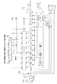
図1は、従来のメモリ回路の構成図である。従来のメモリ回路は、外部クロックCLKを入力しそれに同期した内部クロックCLK1を生成するクロックバッファ10と、内部クロックCLK1に同期してコマンドを入力するコマンドデコーダ11、アドレスを入力するアドレスバッファ12、データの入出力を行うデータ入出力バッファ13を有する。更に、制御回路14は、コマンドデコーダ11が入力したコマンドCMDに応答して、メモリコア15の動作を制御する。メモリコアの動作制御も、内部クロックCLK1に同期して行われる。
【0004】
上記のようにクロック同期型のDRAM(SDRAM)は、リフレッシュ動作として、オートリフレッシュとセルフリフレッシュとを有する。オートリフレッシュは、通常の読み出し・書き込み動作の間に定期的に実施されるリフレッシュ動作であり、外部から供給されるオートリフレッシュコマンドにより実行される。即ち、外部からオートリフレッシュコマンドが入力されると、コマンドデコーダ11がオートリフレッシュコマンドAR1を生成し、それに応答してリフレッシュ制御回路16が内部リフレッシュコマンドREFを生成する。この内部リフレッシュコマンドREFにより、制御回路14がリフレッシュ動作を制御する。セレクタ18は、リフレッシュアドレスカウンタ17からのアドレスを選択し、アドレスラッチ回路19に出力する。
【0005】
一方、セルフリフレッシュは、パワーダウンモード状態の間に、内部のオシレータOSCが自動的に生成するリフレッシュタイミングに応答して、メモリデバイス側が自分で実施するリフレッシュ動作である。パワーダウンモード状態では、外部からコマンド(読み出しと書き込み)が供給されないので、任意のタイミングで生成されるリフレッシュタイミングに応答して、リフレッシュ制御回路16が内部リフレッシュコマンドREFを生成する。これにより、制御回路14がリフレッシュ動作を制御する。
【0006】
以上の様に、通常動作状態の間は、外部からコマンドが供給されるので、リフレッシュコマンドも外部から供給してもらい、それに応答してリフレッシュ動作を実行する。また、パワーダウン状態の間は、外部からコマンドを供給されないので、内部で自動的にリフレッシュタイミングを生成し、リフレッシュ動作を実行する。
【0007】
【発明が解決しようとする課題】
上記の通り、従来のメモリ回路では、メモリ回路を制御するメモリコントローラは、通常動作状態の間ではリフレッシュタイミングの制御を行う必要がある。即ち、メモリコントローラは、タイマーを搭載し、リフレッシュタイミングになるたびにオートリフレッシュコマンドをメモリ回路に発行する必要がある。従って、メモリコントローラは、メモリ回路の制御が複雑になるという課題を有する。
【0008】
従来のメモリ回路では、クロックに同期して供給される読み出し、書き込みコマンドに応答して、制御回路14が対応する制御を実行する。その場合、制御回路14が前の内部動作を実行中であると、新たに供給されたコマンドに応答して以前の内部動作にかかわらず次の内部動作を実行することになる。或いは、以前の内部動作を実行中に、外部から新たなコマンドが供給されると、そのコマンドを拒否するメモリ回路も提案されている。
【0009】
上記後者の場合、即ち、メモリコントローラからのコマンドを拒否することは、好ましくないので、一般のメモリ回路は、前者のように、供給されたコマンドに応答して内部動作をそのまま実行する。従って、通常動作状態において、メモリ回路内で自発的にリフレッシュコマンドを発行してリフレッシュ動作を実行すると、その動作中に供給されるコマンドによって、そのリフレッシュ動作がディスターブされてしまう。また、後者のように供給されるコマンドを拒否すると、メモリコントローラの制御はますます複雑化する。
【0010】
そこで、本発明の目的は、メモリコントローラからのリフレッシュコマンドを受信することなく、自動的にリフレッシュ動作を実行することができるメモリ回路を提供することにある。
【0011】
本発明の別の目的は、通常動作時において、外部からのリフレッシュコマンドを必要とせずに、自動的にリフレッシュ動作を実行することができ、更に、外部からの通常コマンドに応答して高速に内部動作を実行することができるメモリ回路を提供することにある。
【0012】
更に、本発明の別の目的は、外部コマンドの供給を受ける以外に内部コマンドを自動的に発行して、外部コマンドに対応する動作をディスターブすることなく内部コマンドを実行することができる集積回路装置を提供することにある。
【0013】
【課題を解決するための手段】
上記の目的を達成するために、本発明の第1の側面は、集積回路装置において、クロックに同期してコマンドを受信し内部に第1の内部コマンドを生成する第1の回路と、所定のサイクルで内部に第2の内部コマンドを生成する第2の回路とを有することを特徴とする。そして、内部回路が、第1の内部コマンドに従って対応する内部動作をクロック同期動作で実行し、第2の内部コマンドが発行されると、第2の内部コマンドに対応する内部動作と、第1の内部コマンドに対応する内部動作とをクロック非同期動作で順次実行する。
【0014】
より好ましい実施例では、前記集積回路装置は、リフレッシュ動作が必要なメモリ回路であり、前記第1の内部コマンドは、読み出し又は書き込みコマンドであり、前記第2の内部コマンドは、リフレッシュコマンドであり、内部回路はメモリ制御回路である。即ち、この実施例によれば、通常状態では、メモリ制御回路が、クロック同期で受信したコマンドに従って、第1の内部コマンドに対応する制御動作をクロック同期動作で実行する。そして、内部で第2の内部コマンドとしてリフレッシュコマンドが発生すると、メモリ制御回路は、クロック非同期動作で、そのリフレッシュコマンドと第1の内部コマンドに対応する制御動作を順次実行する。やがて、内部動作サイクルが外部動作サイクルに追いつくと、メモリ制御回路は、再度クロック同期動作で第1の内部コマンドに対応する制御動作を実行する。
【0015】
別の好ましい実施例では、集積回路装置が、外部クロックに同期した第1の内部クロックと、前記外部クロックより高速の第2の内部クロックとを発生する内部クロック発生回路を更に有し、前記内部回路は、通常時は、第1の内部コマンドに対応する内部動作を第1の内部クロックに同期して実行し、第2の内部コマンドが発生されると、当該第2の内部コマンドに対応する内部動作と、第1の内部コマンドに対応する内部動作とを第2の内部クロックに同期して実行する。
【0016】
本発明の第1の側面は、非同期のメモリ回路にも適用できる。この場合、外部コマンドの供給が許される最短外部コマンドサイクルがスペックで定められ、メモリ制御回路がその最短外部コマンドサイクルより短い内部動作サイクルを有する。そして、メモリ制御回路は、通常動作時は、外部コマンドに応答して内部動作を実行し、内部リフレッシュコマンドが発生した時は、内部動作サイクルで連続して内部動作を実行する。
【0017】
本発明の第2の側面は、クロック同期型の集積回路装置において、M(M≧2)回の外部動作サイクルに対して、Mより多いN(M<N<2M)回の内部動作サイクルを有することを特徴とする。そして、M回の外部動作サイクルに対して、最大でM回の外部コマンドに対応するM回の内部動作サイクルと、外部コマンドに対応しない内部コマンドに対応する少なくとも1回の内部動作サイクルとが割り当てられる。即ち、内部動作サイクルを外部動作サイクルよりも僅かに短くすることで、M回の外部動作サイクルからなる拡大動作サイクル内で発生するかもしれない内部コマンドの実行を可能にする。
【0018】
上記第2の側面におけるより好ましい実施例では、リフレッシュ動作が必要なメモリ回路に適用される。その場合、M回の動作サイクルからなる拡大動作サイクルの間に、内部でリフレッシュコマンドが発生すると、(N−M)回の内部動作サイクルを利用して、そのリフレッシュ動作を実行する。この(N−M)回は、拡大動作サイクル内の内部動作サイクル回数Nと外部動作サイクル回数Mの差である。しかも、外部コマンドの入力からリードデータ出力までのレイテンシを複数クロックにすることで、外部のメモリコントローラに対しては、連続する外部コマンドに対応して連続してリードデータを出力することが可能になる。
【0019】
上記好ましい実施例のメモリ回路では、M個の外部クロックからなる拡大動作サイクルの間に、N個の内部クロックを発生する内部クロック発生回路が設けられる。そして、外部コマンドは、外部クロックに同期して(又は所定の位相差を持って)入力され、内部コマンドは内部クロックに同期して生成される。また、リードデータは、遅延内部クロックに同期してメモリコアから出力され、データ出力端子からは外部クロックに同期して出力される。同様に、ライトデータは、外部クロックに同期してデータ入力端子から入力され、内部クロックに同期してメモリコアに入力される。従って、外部クロックと内部クロックとの位相差が、コマンドやデータの入出力回路部で吸収される。
【0020】
上記第2の側面における別の好ましい実施例では、同様に、リフレッシュ動作が必要なメモリ回路に適用される。その場合、M回の動作サイクルからなる拡大動作サイクルの間に、内部でリフレッシュコマンドが発生すると、(N−M)回の内部動作サイクルを利用して、そのリフレッシュ動作を実行する。更に、リフレッシュ動作は、複数回の内部動作サイクルに分轄されて実行されることもできる。そうすることにより、外部コマンドの入力からリードデータの出力までのレイテンシ(アクセスタイム)を短くすることができ、高速動作を保証することができる。
【0021】
上記の別の好ましい実施例では、リフレッシュ動作を、ワード線駆動動作と、メモリセルへの再書き込み動作とに分ける場合は、リフレッシュ動作時のリフレッシュアドレス(ローアドレス)とその後のリードまたはライト動作のアドレス(ローアドレス)とが一致する場合は、前半のリフレッシュ動作時に読み出して保持しておいたデータが、その後のリードまたはライト動作用の読み出しデータとして利用される。これにより、前半のリフレッシュ動作時にメモリセルのデータが破壊されていても、何らその後の動作に支障を与えない。
【0022】
本発明の第3の側面は、上記第2の側面において、外部コマンドの入力を制御する外部クロックが、外部動作サイクルよりも短いサイクルの場合に、外部クロックに同期して入力される外部コマンドに応じて、第2の内部動作サイクルが生成されることを特徴とする。従って、第3の側面が、メモリ回路に適用される場合は、リフレッシュコマンド発生回路は、外部コマンドの入力状況に応じて、リフレッシュコマンドを発生する。
【0023】
第3の側面によれば、高速クロックのシステム内に搭載される集積回路装置やメモリ回路であっても、自主的に第2の内部動作サイクルを生成して実行することができる。
【0024】
【発明の実施の形態】
以下、図面を参照して本発明の実施の形態例を説明する。しかしながら、かかる実施の形態例が、本発明の技術的範囲を限定するものではない。また、以下の実施の形態例は、メモリ回路を例にして説明するが、本発明はメモリ回路に限定されず一般的な集積回路装置にも適用できる。
【0025】
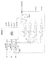
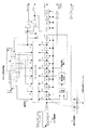
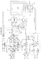
[第1の実施の形態例]
図2は、第1の実施の形態例におけるメモリ回路の全体構成図である。図1と同じ要素には同じ引用番号を与えている。外部から供給される外部クロックCLKがクロックバッファ10に入力され、それに同期し位相が僅かにずれた内部クロックCLK1が生成される。この内部クロックCLK1は、図示しないが、コマンドデコーダ・レジスタ11,アドレスバッファ・レジスタ12,データ入出力バッファ・レジスタ13,メモリ制御回路14,リフレッシュコマンド発生回路20などの各回路に供給され、クロックに同期した動作に寄与する。クロックイネーブル信号CKEは、通常状態とパワーダウン状態とを示す信号である。
【0026】
第1の実施の形態例におけるメモリ回路は、コマンドデコーダ・レジスタ11が、クロックCLK1に同期してコマンドCMDを受信し、リードコマンドRDまたはライトコマンドWRを生成し、メモリ制御回路14に供給する。また、リフレッシュコマンド発生回路20は、内蔵するリフレッシュタイマ21が一定のリフレッシュサイクルで発生するリフレッシュタイマ信号REFTMに応答して、リフレッシュコマンドREFを生成する。リフレッシュコマンド発生回路20は、従来例と異なり、通常状態でもパワーダウンモードでも、リフレッシュタイマ信号REFTMに応答して、リフレッシュコマンドREFを生成する。
【0027】
メモリ制御回路14は、通常は、内部コマンドRD,WRに従って、リード制御動作またはライト制御動作をクロック同期動作で実行する。また、リフレッシュコマンドREFが生成されると、メモリ制御回路14は、クロック非同期動作で、リフレッシュ制御動作または後続する内部コマンド制御動作を実行する。制御回路14は、例えば、ワード線駆動信号、センスアンプ活性化信号、コラム選択信号、プリチャージ信号などをメモリコア15に供給することにより、コマンドに対応する制御動作を実行する。
【0028】
その為に、メモリ制御回路14は、1つの動作サイクルが終了すると次のコマンドを受け付けるコマンド受付信号CMDENを生成する。また、コマンド受付信号CMDEN発生後に内部コマンドRD,WR,REFを受け付けると、コマンドデコーダ・レジスタ11にリセット信号RST1を、リフレッシュコマンド発生回路20にリセット信号RST2を供給し、それぞれの内部コマンドをリセットする。
【0029】
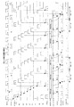
図3は、クロック同期動作とクロック非同期動作を示す図である。図3(A)はクロック同期動作を説明する図である。コマンドRD,WRは、クロックCLK1に同期して入力、生成され、コマンドレジスタ11により保持される。また、メモリ制御回路14は、コマンドレジスタ11が保持する内部コマンドRD,WRを、コマンド受付信号CMDENがHレベルの間に取り込む。そして、内部コマンドに対応する制御動作を実行する。
【0030】
メモリコア15は、メモリセルアレイを有するが、このメモリセルアレイでの最小動作サイクルは、ワード線立ち上げta、ビット線増幅tb、ワード線立ち下げtc、ビット線プリチャージtdからなる。これらが、メモリセルアレイ動作期間tmcaを構成する。
【0031】
通常の同期型DRAMでは、製造プロセスによるバラツキなどを考慮して、クロックCLK1に同期してメモリセルアレイ動作期間tmcaが繰り返されても、そのメモリセルアレイ動作期間tmcaの間に、コマンド待ち時間t1を有する。従って、図3(A)に示される通り、メモリセルアレイ動作期間tmcaが終了してコマンド受付信号CMDENが生成されても、コマンド待ち時間t1後でなければ、新しいコマンドが入力されない。そして、新しいコマンドが入力されてから、メモリ制御回路14にその内部コマンドが取り込まれ、対応する制御動作が開始する。その結果、メモリセルアレイ動作期間tmcaは、クロックCLK1に同期して繰り返される。
【0032】
次に、図3(B)は、クロック非同期動作を示す。コマンドRD,WRは、クロックCLK1に同期して保持されるか、図示しないリフレッシュコマンドREFが非同期で生成される。そして、メモリセルアレイ動作期間tmcaが終了した時点で、すでに内部コマンドRD,WR,REFが発生しているので、メモリ制御回路14は、コマンド受付信号CMDENに応答して、その内部コマンドを受け付け、対応するメモリセルアレイ動作期間が開始される。従って、この場合は、メモリセルアレイ動作期間tmcaの間には、コマンド待ち時間t1が存在せず、最小動作サイクルでメモリセルアレイ動作が繰り返される。
【0033】
クロック非同期動作を行う場合は、コマンド待ち時間t1が存在しないので、クロックCLK1の位相から遅れてメモリセルアレイ動作が開始されても、複数のコマンドを最小動作サイクルで実行することで、メモリセルアレイ動作はやがてクロックCLK1の位相に追いつくことができる。
【0034】
以上の様に、クロック同期動作は通常動作であり、クロック非同期動作は高速動作に対応する。この通常動作と高速動作の切り替えは、コマンドレジスタ11が保持する内部コマンドと動作期間が終了した時に発生するコマンド受付信号CMDENとの論理積をとることにより、簡単に行うことができる。即ち、コマンド受付信号CMDENが先に発生すれば、後からクロックに同期して生成される内部コマンドに従ってメモリセルアレイ動作期間が開始される。従って、この場合は、図3(A)のクロック同期動作(通常動作)である。逆に、内部コマンドが先に存在すれば、後から生成されるコマンド受付信号CMDENに応答して、待ち時間t1なしでメモリセルアレイ動作期間が開始される。この場合は、図3(B)のクロック非同期動作(高速動作)である。
【0035】
そして、メモリセルアレイがコマンドに応じた動作を開始したら、コマンド受付信号CMDENをリセットすると共に、コマンドレジスタ11の内部コマンドをリセットする。また、リフレッシュコマンド発生回路20のリフレッシュコマンドをリセットする。
【0036】
図4は、メモリ制御回路14の構成例を示す図である。メモリ制御回路14は、内部コマンドに対応して、メモリコア15に各種制御信号φを供給する制御信号発生回路24と、内部コマンド入力バッファ25,26,27とを有する。制御信号には、ワード線を駆動するワード線駆動信号φWLと、ビット線対とセンスアンプとの間のビット線トランスファーゲートを駆動するビット線トランスファーゲート信号φBTRと、センスアンプを活性化する活性化信号φLEと、コラムゲート駆動信号φCLと、プリチャージ信号φPREなどが含まれる。
【0037】
更に、メモリ制御回路14は、入力パルスの立ち下がり時にパルスを発生するパルス生成回路28,30,32,33と、コマンド受付信号CMDENを生成するフリップフロップFFを有する。内部コマンドRD,WR,REFは、例えばLレベルで非活性状態、Hレベルで活性状態とする。
【0038】
図5は、リフレッシュコマンドが発生した時のクロック同期動作からクロック非同期動作に移行する場合を示すタイミングチャート図である。クロックCLK1の立ち上がりエッジC1まで、メモリセルアレイはクロックに同期した通常動作を繰り返しているとする。従って、クロックの立ち上がりエッジC1の前に、コマンド受付信号CMDENが発生している。また、クロックの立ち上がりエッジC1より前に、リフレッシュタイマ信号REFTMが発生しているとする。
【0039】
動作サイクル1より前にリフレッシュタイマ信号REFTMが発生すると、リフレッシュコマンド発生回路20は、その後のクロック立ち上がりエッジC1から所定時間遅延後に、リフレッシュコマンドREFを発生する。これにより、外部からのコマンドに対応する内部コマンドRD(A0)を優先して受け付けて、内部の動作サイクルを実行することができる。
【0040】
立ち上がりエッジC1で発生した内部コマンドRD(A0)(読み出しコマンド)は、コマンド受付信号CMDENが受け付け状態であるので、クロックCLK1に同期してメモリ制御回路14のコマンド入力バッファ25に入力される。従って、制御信号発生回路24により各種制御信号が発生され、サイクル1は、リーディングエッジC1から開始する。サイクル1では、読み出し動作のためにワード線駆動信号φWL、センスアンプ活性化信号φLE、コラム選択信号φCLなどが生成し、最後にプリチャージ信号φPREが生成される。そして、プリチャージ期間が終了すると、フリップフロップFFはコマンド受付信号CMDENを発生する。尚、内部コマンドRD(A0)の動作が開始されると、リセット信号RST1によりコマンドはリセットされる。
【0041】
この時点で、リフレッシュコマンドREFが生成されているので、コマンド受付信号CMDENに応答して、コマンド入力バッファ27がこのコマンドREFを入力し、制御信号発生回路24が、リフレッシュ動作に対応して各種制御信号φを発生する。実際には、リフレッシュ動作は読み出し動作と同じである。そして、コマンドREFを入力すると、リセット信号RESETが生成され、コマンド受付信号CMDENがLレベルになる。同時に、リセット信号RST2が生成され、リフレッシュコマンドREFがリセットされる。従って、リフレッシュコマンドに対応するサイクル2の動作は、待ち時間t1を介在することなく、クロック立ち上がりエッジC2より前に開始される。つまり、クロック非同期動作である。
【0042】
リフレッシュ動作が終了すると、再度コマンド受付信号CMDENが生成される。この時、既にクロックエッジC2に同期して内部コマンドRD(A1)がコマンドレジスタ11に保持されている。従って、この内部コマンドRD(A1)がコマンド受付信号CMDENに応答して、コマンド入力バッファ25に入力され、次のサイクル3の動作が開始する。この動作もクロック非同期動作である。
【0043】
以下、同様にして、クロックエッジに同期して生成された内部コマンドが、順次クロック非同期動作で実行される。クロック非同期動作では、待ち時間なしの高速動作であるので、やがて内部動作サイクルがクロックCLK1のサイクルに追いつき、コマンド受付信号CMDENがクロックCLK1の立ち上がりエッジの位相より早まることになる。その結果、内部動作サイクルは、待ち時間t1を間に挟んでクロックCLK1に同期したクロック同期動作になる。
【0044】
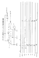
図6は、第1の実施の形態例におけるクロック同期動作とクロック非同期動作(高速動作)とを示すタイミングチャート図である。図6は、図5の動作をより多くの動作サイクルで示している。外部からのコマンドCMDは、クロックCLK1に同期して供給され、コマンドレジスタ11により内部コマンドが保持される。図6の例は、リードコマンドRDが連続して供給されている。
【0045】
最初は、クロックCLK1に同期して内部動作サイクルRD0-2が実行される。内部動作サイクルRD1の時にリフレッシュタイマがリフレッシュタイマ信号REFTMを生成すると、一定の遅延後に内部リフレッシュコマンドREFが出力される。そして、内部動作サイクルRD2が終了すると、即リフレッシュコマンドREFに従う内部動作サイクルが開始する。その後は、クロック非同期動作に移行し、内部動作サイクルRD3-7までが高速動作になる。やがて、内部動作サイクルがクロックCLK1のサイクルに追いつくと、再度内部動作サイクルRD8以降がクロック同期動作になる。
【0046】
即ち、連続されて入力されるリードコマンドに対して、全てを入力して保持し、必要に応じてリフレッシュ動作サイクルを割り込ませ、クロック非同期の高速動作で保持されたリードコマンドを実行する。従って、データ出力端子DQには、読み出しデータが連続して出力され、メモリコントローラは、内部のリフレッシュ動作は見えず、通常の連続読み出しが行われているように見える。
【0047】
図7は、より低速の外部クロックの場合におけるクロック同期動作とクロック非同期動作(高速動作)とを示すタイミングチャート図である。この場合は、内部の高速動作(クロック非同期動作)サイクルが、クロックCLK1に比較してかなり短い。従って、リフレッシュコマンドREF発生後のリフレッシュ動作サイクルREFからクロック非同期動作になるが、その高速動作は次のリード動作サイクルRD3までで、その後はクロック同期動作になる。つまり、リフレッシュ動作実行後に内部動作サイクルがクロックCLK1のサイクルに追いつくまでの期間が短くなる。
【0048】
図8は、更に低速の外部クロックの場合におけるクロック同期動作とクロック非同期動作(高速動作)とを示すタイミングチャート図である。この場合は、3番目のリード動作サイクルRDの後でリフレッシュ動作がクロック非同期で行われるが、そのリフレッシュ動作が次のクロックCLK1の立ち上がりエッジより前に終了し、次のリード動作サイクルからクロック同期動作に戻る。
【0049】
図6,7,8のいずれの場合も、外部コマンドの入力から2クロック後にデータ出力端子DQに読み出しデータが出力されるように内部回路を制御することで、通常動作中連続するコマンドを処理中にリフレッシュ動作を割り込ませても、問題なく読み出しデータを連続して出力することができる。
【0050】
図9は、外部クロックCLK1のサイクルに比較して内部動作サイクルが2倍長い場合のクロック同期動作とクロック非同期動作(高速動作)とを示すタイミングチャート図である。メモリデバイスが搭載されるシステム内のクロックCLK1が高速で、それに対してデバイス内部の動作が低速の場合の例である。この場合は、スペック上、外部からのコマンドは、外部クロックCLK1に同期して連続して供給することは許されない。従って、最速で、外部からのコマンドは、奇数番目または偶数番目のクロックの立ち上がりエッジに同期して供給される。この場合でも、図9に示される通り、図6の場合と同様にして内部動作サイクルの間の待ち時間t1を利用して、リフレッシュ動作サイクルを挿入することが可能になる。但し、図9の場合は、外部コマンドの入力から4クロック後に読み出しデータがデータ出力端子DQに出力される。
【0051】
また、奇数番目のクロックに同期してコマンドが入力された後、偶数番目のクロックに同期してコマンドが供給される場合もある。しかし、その場合でも、連続するクロックに同期してコマンドは供給されない。従って、その場合は、コマンドの間に2クロックサイクルが存在することになり、内部のリフレッシュ動作サイクルの挿入に何ら支障は生じない。
【0052】
上記第1の実施の形態例において、リフレッシュタイマ信号REFTMは、クロックCLKに対して、例えば2桁程低い周波数である。従って、数100クロックCLKに対して、リフレッシュタイマ信号REFTMは1回発生する程度である。その結果、数100サイクルの外部動作サイクルに対して、数100サイクルに1サイクル加えた内部動作サイクルになる。全ての外部動作サイクルに対して、内部動作サイクルとリフレッシュ用の動作サイクルの2つの内部動作サイクルが割り当てられる必要はなく、通常動作では高速動作が保証されるのである。
【0053】
[第2の実施の形態例]
第2の実施の形態例は、外部動作サイクルより短い内部動作サイクルでコマンドを実行するメモリ回路である。リフレッシュ動作を必要とするメモリ回路において、メモリ制御回路は、M(M≧2)回の外部動作サイクルに対して、Mより多いN(M<N<2M)回の内部動作サイクルを有する。外部コマンドは、外部動作サイクルに同期して入力される。また、リードデータの出力及びライトデータの入力も、外部動作サイクルに同期して行われる。それに対して、N回の内部動作サイクルは、外部動作サイクルに対応する外部コマンドを実行する第1の内部動作サイクルと、リフレッシュコマンドを実行する第2の内部動作サイクルとを有する。そして、内部でリフレッシュコマンドが発行された場合は、上記第2の内部動作サイクルを利用してリフレッシュ動作が行われる。
【0054】
以上の様に、第2の実施の形態例におけるメモリ回路は、M回の外部動作サイクルからなる拡大動作サイクル内に、M回より多いN回の内部動作サイクルを生成し、(N−M)回の内部動作サイクルを利用して、内部で自動発生するリフレッシュコマンドに対応するリフレッシュ動作を実行する。但し、外部動作サイクルに同期してコマンドやライトデータが入力され、リードデータが出力されるので、メモリコントローラからは、メモリ回路が外部動作サイクルに同期して動作しているように見える。また、M回より1サイクルまたは数サイクル多いN回の内部動作サイクルにすれば、連続するリードコマンドに対して、所定のリードレイテンシの遅れで、外部動作サイクルに同期してリードデータを連続して出力することができる。
【0055】
以下の実施の形態例では、M=7、N=8の場合が説明される。
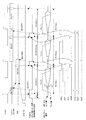
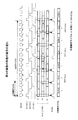
【0056】
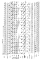
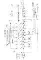
図10は、第2の実施の形態例におけるメモリ回路の構成図である。図2と同じ部分には同じ引用番号が与えられる。また、図11は、その動作タイミングチャート図である。図10のメモリ回路は、図2と比較すると、外部クロックECLKから、外部クロックに同期したクロックECLK1と、内部動作サイクルを制御する内部クロックICLK1〜ICLK3、REF-CLKとを生成するクロック発生回路が設けられる点で異なる。図11に示される通り、内部クロックは、7回の外部動作サイクルに対して発生する8回の内部動作サイクルを画定する。従って、内部クロックの周期は、外部クロックの周期よりもわずかに短い。
【0057】
上記のクロック発生回路35が生成するクロックにおいて、外部クロックECLK1は、外部クロックECLKに同期しており、コマンド、アドレス、データの入出力タイミングを制御する。内部クロックICL1は、外部コマンドを実行する内部動作サイクルの開始を制御する。内部クロックICLK2は、上記クロックICLK1を遅延させたクロックであり、メモリコアから読み出したデータをデータバスBD2に出力するクロックである。出力ラッチクロックICLK3は、データバスDB2に出力されたデータをデータ入出力回路13内の出力レジスタ134に取り込むクロックである。そして、リフレッシュクロックREF-CLKは、リフレッシュ内部動作サイクルを制御するクロックである。
【0058】
従って、図10のメモリ回路では、クロックECLK1に同期して、外部コマンドCMDがコマンドデコーダ11Aに、外部アドレスがアドレスバッファ12Aにそれぞれ入力される。また、データ入出力バッファ13において、クロックECLK1に同期して、リードデータが出力バッファ133から出力され、ライトデータが入力バッファ131に入力される。
【0059】
それに対して、コマンドレジスタ11Bとアドレスレジスタ12Bが、内部クロックICLK1に同期して、コマンドRD,WR及び外部アドレスEAddをメモリ制御回路14やメモリコア15に供給する。同様に、リードデータは、内部クロックICLK2に同期してメモリコアからセンスバッファに出力され、出力ラッチクロックICLK3に同期してデータバスのリードデータがレジスタ134にラッチされる。また、ライトデータは、内部クロックICLK1に同期してレジスタ132にラッチされる。従って、レジスタ11B,12B,134,132は、外部クロックと内部クロックとの位相のずれを吸収して、対応する信号を内部動作サイクルにあわせてラッチし伝達する。
【0060】
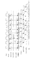
図11のタイミングチャート図は、外部コマンドとしてリードコマンドRead-0〜Read12が、外部クロックECLKに同期して供給される場合を示す。7つの外部クロックECLKからなるサイクルを拡大動作サイクルと称する。この拡大動作サイクルに対して、7個の内部クロックICLK1と1個のリフレッシュクロックREF-CLKが発生する。
【0061】
まず、外部クロックECLK1に同期して、外部コマンドはコマンドデコーダ11Aに入力され、外部アドレスもアドレスバッファ12Aに入力される。最初のリードコマンドRead-0は、内部クロックICLK1に同期してレジスタ11Bにラッチされ、メモリ制御回路14に供給される。そして、内部クロックICLK1に同期して、リード動作サイクルが実行される。メモリコア15から読み出されたリードデータは、内部クロックICLK2に同期してセンスバッファSBによりデータバスDB2に出力され、出力ラッチクロックICLK3に同期して出力レジスタ134にラッチされる。そして、最後に、外部クロックECLK1に同期して、出力バッファ133から出力端子DQにリードデータが出力される。図11の例では、最初のリードコマンドRead-0の入力からリードデータQ0が出力されるまでのレイテンシは、2外部クロックサイクルである。
【0062】
図11の例では、拡大動作サイクル内の2番目の内部動作サイクルが、リフレッシュ動作サイクルに割り当てられる。従って、2番目の内部クロックとしてリフレッシュクロックREF-CLKが発生する。リフレッシュタイマ21によりリフレッシュサイクル毎に発生するリフレッシュタイマ信号REFTMに応答して、リフレッシュコマンド発生回路20は、リフレッシュクロックREF-CLKに同期してリフレッシュコマンドREFを発生する。従って、リフレッシュタイマ信号が生成された時に、拡大動作サイクル内の2番目の内部動作サイクルで、リフレッシュ動作が実行される。リフレッシュ動作では、セレクタ18がリフレッシュアドレスカウンタ17のリフレッシュアドレスRAddを選択して、ローデコーダRDECに供給する。リフレッシュ動作が実行されると、リフレッシュアドレスカウンタ17はカウントアップする。リフレッシュタイマ信号が生成されない場合は、2番目の内部動作サイクルでは、何らの動作も行われない。そして、3番目から8番目までの内部動作サイクルは、残りの6つのリードコマンドRead-1〜Read-6に対応するリード動作が実行される。
【0063】
従って、リフレッシュ動作が割り込まれた後の内部動作サイクルは、外部動作サイクル(外部クロックECLKのサイクル)に比較して、かなり遅延しているが、内部動作サイクルが外部クロックサイクルよりも1/8ずつ短いので、内部動作サイクルは少しずつ外部クロックサイクルに近づき、やがて拡大動作サイクルの最後で追いつく。
【0064】
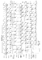
図12は、リードコマンドとライトコマンドとが混在する場合の動作タイミングチャート図である。この場合も、図11の場合と同様に7つの外部クロックに対して、8つの内部動作サイクルが存在する。そして、ライトデータD2は、外部クロックに同期して入力され、内部動作サイクルに同期してライト動作が実行される。また、リードレイテンシが2であるので、リードコマンドRead-1から4クロック後に次のライトコマンドWrite-2が供給される。これにより、入出力端子DBでリードデータQ1とライトデータD2とがコンフリクトすることがさけられる。
【0065】
図13は、クロック発生回路の回路図である。また、図14は、その動作タイミングチャート図である。クロック発生回路35は、外部クロックECLKを入力バッファ39に入力し、パルス幅調整回路40により立ち上がりエッジから3ゲート分のパルス幅を有するクロックECLK1を生成する。従って、このクロックECLK1は、外部クロックECLKと同期し、位相が少し遅れたクロックである。
【0066】
パルス幅調整回路40の出力N1は、位相比較器41の一方の入力に供給されると共に、可変遅延素子D1〜D8を経由して他方の入力にも供給される。そして、位相比較器41により検出される位相差に対して、位相差がなくなるように、遅延制御回路42が遅延制御電圧Vcを出力する。この遅延制御電圧Vcに従って、各可変遅延素子D1〜D8の遅延時間が調整される。
【0067】
従って、各可変遅延素子の出力として、外部クロックECLKの1サイクルを8等分した位相のずれを有する8個の内部クロックN1〜N8が生成される。この内部クロックN1〜N8が、シフトレジスタ37が出力する選択信号S1〜S8に従って、マルチプレクサ38により選択され、内部クロックN10として出力される。シフトレジスタ37は、内部クロックN10のダウンエッジでシフトする。そして、順番に発生する選択信号S1〜S8は、S1,S8,S7….S2の順番で内部クロックN1〜N8を選択する。この結果、内部クロックN10は、外部クロックECLKの7/8サイクルを有する短サイクルのクロックとなり、外部クロックECLKより1/8サイクルづつ位相が進んだクロックになる。
【0068】
この内部クロックN10から、NORゲート44によって、2番目のクロックが除去されて、7個の内部クロックICLK1が生成される。また、NANDゲート43によって、2番目のクロックが選択されて、1個のリフレッシュクロックREF-CLKが生成される。また、内部クロックICLK1に対して、可変遅延素子D9〜D12の遅延時間だけ位相が遅れた内部クロックICLK2が生成される。また、クロックN4からインバータ2段分位相が遅れた出力ラッチクロックICLK3が生成される。クロックN4を選択することにより、内部クロックICLK2のC1とC2及び出力ラッチクロックICLK3のC3,C4,C5とが、C3-C1-C4-C2-C5の順番で生成される。こうすることで、2番目の動作内部サイクルにリフレッシュ動作が挿入されても、連続するリードコマンドに対して、そのリードデータを同じ順番で連続して出力レジスタ134にラッチすることができる。
【0069】
図15は、リフレッシュコマンド発生回路とその動作タイミングチャートとを示す図である。リフレッシュコマンド発生回路20は、遅延フリップフロップ46,47と、NANDゲート48,遅延回路49を有する。動作タイミングチャート図に示される通り、リフレッシュタイマ信号REFTMが発生した後の、リフレッシュクロックREF-CLKに同期して、信号N22がHレベルになり、リフレッシュコマンドREFが生成される。そして、遅延回路49の遅延後に、カウントアップ信号UPが生成され、リフレッシュアドレスカウンタ17のアドレスをカウントアップする。それにより、フリップフロップ46,47はリセットされる。
【0070】
このように、拡大動作サイクル内の8内部動作サイクルのうち、2番目の内部動作サイクルが、リフレッシュ動作用に確保される。そして、リフレッシュタイマ信号REFTMが発生した時は、その直後の2番目の内部動作サイクルで、リフレッシュコマンドREFが生成され、メモリコア15でリフレッシュ動作が実行される。このリフレッシュ動作では、リフレッシュアドレスカウンタからのリフレッシュアドレスRAddに対応するワード線が駆動され、ビット線対に読み出されたデータがセンスアンプSAで増幅され、メモリセルに再書き込みされる。その後、ワード線が立ち下げられ、プリチャージ動作が行われる。
【0071】
[第3の実施の形態例]
第2の実施の形態例では、2番目の内部動作サイクルをリフレッシュ動作サイクルに割り当てている。従って、1番目の内部動作サイクルに対応するリードコマンドのリードアクセス時間(リードレイテンシ)は、図11に示される通り比較的長くなる。これは、2番目の内部動作サイクルの前後のサイクルでのリードデータの出力タイミングを、外部クロックに同期して連続させるためである。
【0072】
これに対して、第3の実施の形態例では、8つの外部動作サイクルの中に、外部コマンドを実行する8つの第1の内部動作サイクルと、リフレッシュ動作を行う2つの第2の内部動作サイクルとを有する。リフレッシュ動作用の第2の内部動作サイクルは、第1の内部動作サイクルの半分程度の長さであり、1回のリフレッシュ動作が2回に分けて行われる。その結果、最悪のリードアクセス時間を、第2の実施の形態例より短くすることができる。
【0073】
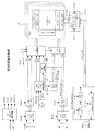
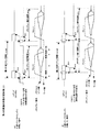
図16は、第3の実施の形態例におけるメモリ回路の構成図である。図10と異なるところは、2つのリフレッシュコマンドREF1,REF2が生成されることと、リフレッシュアドレスRAddと外部アドレスEAddとを比較して比較結果信号を生成する比較器50が設けられていることである。更に、メモリコア15内に、メモリセルのリードデータを一時的に保持するデータレジスタDRGと、セルアレイMCA内の図示しないビット線対とデータレジスタDRGとの間に設けられる転送ゲートTRGとが設けられていることも、図10と異なる構成である。データレジスタDRGは、センスアンプSAと実質的に同じ回路であり、前半のリフレッシュ動作サイクルで、ビット線対の電圧を増幅して保持する。それ以外は、同じ引用番号を与えているので、説明を省略する。
【0074】
図17,18は、第3の実施の形態例のリフレッシュ動作を説明する図である。図17(A)は、通常のリフレッシュ動作とリードまたはライト動作を示す。いずれの場合も、ローアドレスにより選択されたワード線WLを駆動して、メモリセル内のデータをビット線対BL,/BLに読み出し、それをセンスアンプSAで増幅し、再書き込みの後に、プリチャージを行う。
【0075】
図17(B)は、本実施の形態例でのリフレッシュ動作を示す。本実施の形態例でのリフレッシュ動作は、2つのリフレッシュ動作サイクルREF1,REF2に分けて実行される。最初のリフレッシュステップ1では、ワード線を駆動して被リフレッシュメモリセルを選択し、そのデータをビット線対と転送ゲートTRGを介して、データレジスタDRGに転送する。データレジスタDRGは、実質的にセンスアンプと同じ回路であり、ビット線対を増幅することができ、そのデータを保持する。次にリフレッシュステップ2では、被リフレッシュメモリセルを再度選択して、データレジスタが保持するデータを転送ゲート経由でメモリセルに再書き込みする。いずれのリフレッシュステップでも、最後にプリチャージを行う。更に、2つのリフレッシュステップの間に、外部コマンドに対応する通常のリードまたはライト動作サイクルが挿入される。
【0076】
図18(C)は、本実施の形態例での別のリフレッシュ動作を示す。リフレッシュ動作を2つの動作サイクルに分割したことにより、最初のリフレッシュステップ1では、被リフレッシュメモリセルのデータが破壊される。数内部動作サイクル後のリフレッシュステップ2でデータレジスタから再書き込みが行われるが、その間の通常内部動作サイクルで、被リフレッシュメモリセルと同じローアドレスがアクセスされると、リードまたはライト動作を正常に行うことができない。
【0077】
そこで、図18に示される通り、被リフレッシュメモリセルのローアドレスAaと、その後の通常内部動作のローアドレスAaとが一致する場合は、その内部動作サイクルにおいて、転送ゲートTRGを開いて、データレジスタDRGが保持するデータをリードし、またはライトアンプWAからライトデータに応じたデータをデータレジスタDRGに書き込む。従って、この時の内部動作サイクルでは、必ずしもワード線を駆動する必要はない。
【0078】
その後のリフレッシュステップ2では、ワード線が駆動され、再度転送ゲートTRGが開かれて、データレジスタDRGに保持されたデータが、ビット線対を経由してメモリセルに書き込まれる。これにより、リード動作の再書き込みと、ライト動作の再書き込みとが行われる。
【0079】
そのために、図16に示した通り、アドレス比較器50が設けられ、比較結果信号に応じて、メモリ制御回路14が転送ゲートTRGの開閉を制御する。このアドレス比較器50は、最初のリフレッシュコマンドREF1と次のリフレッシュコマンドREF2との間の期間だけ、比較器50にイネーブル信号ENを出力し、その期間内でリフレッシュアドレスRAddと外部アドレスEAddとを比較させる。
【0080】
図19は、第3の実施の形態例におけるタイミングチャート図である。8回の外部動作サイクルに対して、10回の内部動作サイクルが発生する。そして、2番目と7番目に2つに分割されたリフレッシュ動作サイクルRef1-aとRef2-aとが実行される。従って、リフレッシュ動作サイクルは、外部コマンドを実行する4回の通常内部動作サイクル毎に実行される。しかも、リフレッシュ動作が2回に分割されているので、個々のリフレッシュ動作サイクルは、通常の内部動作サイクルの約半分の時間で終了する。その結果、リードコマンドRead-0に対するアクセス時間が図11に比較して短くなる。これは、内部動作サイクルRead-0の後のリフレッシュ動作サイクルRef1-aの時間が短いので、内部動作サイクルRead-0の出力データQ0と後続する内部動作サイクルRead-1の出力データQ1とを連続させても、出力データQ0をそれほど遅くする必要がないからである。
【0081】
図19に示される通り、8個の外部クロックECLKに対して、外部コマンドの実行を制御する8個の内部クロックICLK1と、2個のリフレッシュクロックREF-CLKとが生成される。これにより、10の内部動作サイクルが生成される。
【0082】
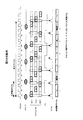
図20は、第3の実施の形態例に適用するクロック発生回路35を示す図である。図13と同じ引用番号が与えられる。また、図21は、その動作タイミングチャート図である。図13のクロック発生回路と異なり、図20のクロック発生回路は、シフトレジスタ37が、5段構成になっている。そして、シフトレジスタ37が生成する選択信号S1,S5,S4,S3,S2がマルチプレクサ38に与えられ、内部クロックN10として、N1,N8,N4,N3,N2の順番に選択される。従って、4個の外部クロックECLKに対して、5個の内部クロックN10が生成される。
【0083】
そして、NANDゲート43により、クロックN8のタイミングの内部クロックN10が選択されて、リフレッシュクロックREF-CLKが生成される。また、NORゲート44により、クロックN8のタイミングの内部クロックN10が除去されて、内部動作サイクルを開始する内部クロックICLK1が生成される。内部クロックICLK1は、遅延素子D9-D12により遅延され、別の内部クロックICLK2となる。図20には、出力ラッチクロックICLK3の生成回路は、省略されている。
【0084】
図22は、第3の実施の形態例に適用するリフレッシュコマンド発生回路とその動作タイミングチャート図である。図15に示した第2の実施の形態例に適用されるリフレッシュコマンド発生回路と比較すると、図22のリフレッシュコマンド発生回路は、フリップフロップ60,61,62及びNANDゲート63が追加されている。従って、フリップフロップ46,47とNANDゲート48とで、リフレッシュタイマ信号REFTMが生成してから、次のリフレッシュクロックREF-CLKに同期して、第1のリフレッシュコマンドREF1が生成される。そして、フリップフロップ60,61,62及びNANDゲート63により、リフレッシュタイマ信号REFTMが生成してから、2番目のリフレッシュクロックREF-CLKに同期して、第2のリフレッシュコマンドREF2が生成される。そして、フリップフロップ64により、第1のリフレッシュコマンドREF1が生成されてから、第2のリフレッシュコマンドREF2が生成されるまでの期間、比較器イネーブル信号ENが生成される。また、第2のリフレッシュコマンドREF2が生成されてから後に、遅延回路49を介してカウントアップ信号UPが生成される。
【0085】
図10に示した第2の実施の形態例と、図16に示した第3の実施の形態例において、クロックイネーブル信号CKEが外部から供給されている。このクロックイネーブル信号CKEは、通常動作状態とパワーダウン状態とを指示する信号である。即ち、クロックイネーブル信号CKEがHレベルの時が通常動作状態(活性状態)であり、Lレベルの時がパワーダウン状態である。パワーダウン状態では、クロック発生回路35が各種クロックの発生を停止する。その結果、外部クロックCLK1が供給されるコマンド、アドレス、データの入出力回路は、外部信号の入力や出力を停止する。また、メモリ制御回路14も外部コマンドに対応する動作を停止する。
【0086】
図23は、パワーダウン状態でのリフレッシュコマンド発生回路とその動作タイミングチャートを示す図である。図15のリフレッシュコマンド発生回路と比較すると、NANDゲート66,67が追加され、クロックイネーブル信号CKEが供給されている。
【0087】
タイミングチャート図に示される通り、クロックイネーブル信号CKEがHレベルの通常動作状態の時は、図15と同様に、リフレッシュタイマ信号REFTMが生成した後に、リフレッシュクロックREF-CLKに同期してリフレッシュコマンドREFが生成される。一方、クロックイネーブル信号CKEがLレベルのパワーダウン状態では、リフレッシュタイマ信号REFTMが生成すると即リフレッシュコマンドREFが生成される。パワーダウン状態では、リフレッシュクロックREF-CLKが生成されないからである。
【0088】
[第4の実施の形態例]
第2及び第3の実施の形態例では、外部動作サイクルと外部クロックサイクルとが同じである。しかし、高速クロックに同期したシステムに搭載される集積回路装置やメモリ回路は、内部動作サイクルよりも2倍以上短いサイクルの高速外部クロックに対して内部動作を行う必要がある。その場合は、外部動作サイクルは、集積回路装置やメモリ回路の内部動作サイクルと整合した長さになる。
【0089】
第4の実施の形態例は、例えば外部動作サイクルが20nsに対して外部クロックサイクルが10nsのような場合に適用されるメモリ回路である。即ち、このメモリ回路は、外部動作サイクルが50MHzで動作可能であり、更に、クロックサイクルが100MHzのシステムに搭載することができる。かかる場合、高速クロックで動作するシステムは、メモリ回路の動作サイクルにあわせて、コマンド入力の間隔が2クロック以上に制約される。従って、最も高速なコマンド入力でも、一つおきの外部クロックに同期して外部コマンドが入力される。また、外部コマンドは、奇数外部クロックエッジと偶数外部クロックエッジのいずれかに同期して入力することが許される。その結果、奇数クロックエッジで外部コマンドが供給された後に、偶数クロックエッジで次の外部コマンドを供給する場合は、間に2外部クロックを挟まなければならない。
【0090】
図24は、第4の実施の形態例におけるメモリ回路を示す図である。図25〜28は、第4の実施の形態例の動作タイミングチャート図である。図25はその基本的動作を、図26は外部クロックECLKの位相a側で外部コマンドが入力される動作を、図27は外部クロックECLKの位相b側で外部コマンドが入力される動作を、図28は外部クロックECLKの位相a側とb側の両方でアトランダムに外部コマンドが入力される動作をそれぞれ示す。
【0091】
このように、第4の実施の形態例では、外部動作サイクルと内部動作サイクルとの位相関係が2種類存在する。即ち、図26と図27の2種類である。従って、図26に示される通り、位相a側で外部コマンドが入力される場合は、7個の外部動作サイクルからなる拡大サイクル内に生成される8個の内部動作サイクルのうち、2番目の内部動作サイクルがリフレッシュ動作用に割り当てられる。一方、図27に示される通り、位相b側で外部コマンドが入力される場合は、8個の内部動作サイクルのうち、6番目の内部動作サイクルがリフレッシュ動作用に割り当てられる。更に、図28に示される通り、外部コマンドがランダムに入力される場合は、リフレッシュ動作用の内部動作サイクルをあらかじめ定めることができない。従って、第4の実施の形態例では、外部コマンドの入力状況に応じてリフレッシュ動作用サイクルが決定される。具体的には、リフレッシュコマンド発生回路20が、2つの連続外部クロックに同期した外部コマンドの入力状況に応じて、リフレッシュコマンドの発生を許可する状態になる。
【0092】
更に、メモリ回路側は、いずれの位相で外部コマンドが供給されるか予測できないので、外部コマンドを入力するコマンドデコーダ11Aは、外部クロックに同期して、位相a,b側の両方で外部コマンドを入力して内部コマンドを保持しなければならない。従って、図24に示される通り、コマンドレジスタ11Bは、外部クロックの位相aで入力される外部コマンドに対する内部コマンドを保持するレジスタ1aと、位相bの内部コマンドを保持するレジスタ1bとを有する。これらレジスタ1a,1bは、外部クロックECLKを2分周したクロックECLK1-aとECLK1-bとの同期して、コマンドを保持する。
【0093】
これらの初段のレジスタ1a,1bの内部コマンドは、スイッチSW1a,SW1bを介して、後段のレジスタ2に、内部クロックICLK1に同期して保持される。内部クロックICLK1は、前述の実施の形態例と同様に外部動作サイクルの8/7倍の周波数(7/8倍のサイクル)を有する。後段レジスタ2は、例えばOR論理入力を有し、前段レジスタ1a,1bのいずれか一方に保持された内部コマンドを保持する。前段レジスタ1a,1bに内部コマンドが保持されていない場合は、後段レジスタ2は、内部コマンドを保持しない。
【0094】
コマンドレジスタ11Bをこのような構成にして、図25のコマンドレジスタ1a,1bに記入される通り、各内部動作サイクルでは、スイッチSW1,SW2を同時に導通させて、両初段レジスタ1a,1bの内部コマンドを同時に後段レジスタ2に転送する。いずれか一方の位相a,bで外部コマンドが入力されるので、その一方の内部コマンドRD,WRが、後段レジスタ2に転送され、制御回路14により実行される。
【0095】
更に、拡大サイクル内の8個の内部動作サイクルのうち、2番目の内部動作サイクルでは、初段レジスタ1bのみを後段レジスタ2に転送する。同様に、6番目の内部動作サイクルでは、初段レジスタ1aのみを後段に転送する。そして、リフレッシュコマンド発生回路20は、後段レジスタ2が何らかの内部コマンドRD,WRを保持している場合は、リフレッシュコマンドの発生を禁止され、いずれの内部コマンドRD,WRも保持していない場合は、リフレッシュコマンドの発生を許可される。
【0096】
上記の動作が意味するところは、次の通りである。2番目の内部動作サイクルでは、初段レジスタ1bのみを監視するので、外部クロック1bで外部コマンドが入力しなかった場合は、リフレッシュ動作サイクルRefに割り当てられることになる。この動作は、図26に示される。次に、6番目の内部動作サイクルでは、初段レジスタ1aのみを監視するので、外部クロック5aで外部コマンドが入力しなかった場合は、リフレッシュ動作サイクルRefに割り当てられる。この動作は、図27に示される。
【0097】
そして、通常の内部動作サイクルであっても、外部クロックECLKの両位相a,bで連続して外部コマンドが入力されない場合も、後段レジスタ2が内部コマンドを保持しないので、リフレッシュ動作サイクルとして割り当てられる。この動作は、図28に示される。図28の様に、外部クロックの両位相a,bでランダムに外部コマンドが入力される場合は、外部コマンドの間に2外部クロックのインターバルが必要になるので、リフレッシュ動作サイクルとなる内部動作サイクルは多くなる。
【0098】
以上の様に、外部コマンドの入力状況に応じて、内部動作サイクルがリフレッシュ動作サイクルに割り当てられる。そして、リフレッシュコマンド発生回路20は、リフレッシュタイマ信号REFTMが発生した時に、リフレッシュ動作サイクルでリフレッシュコマンドを発生する。
【0099】
図26,27,28に示される通り、内部クロックICLK1は、7個の外部動作サイクル(2外部クロックECLKサイクルに該当)に対して、8個生成される。そして、データバスDB2へのリードデータの出力を制御する第2の内部クロックICLK2は、第1の内部クロックICLK1から遅延すると共に、リフレッシュ動作サイクルの時のクロックを除いて生成される。更に、出力ラッチクロックECLK-Lは、外部コマンドの入力が位相aかbかに応じて、外部クロックECLKの一方のクロックを、所定時間遅延させて生成される。出力ラッチクロックECLK-Lは、従って、外部クロックに同期したクロックである。図26では、出力ラッチクロックECLK-Lは、位相aの外部クロックECLKを遅延したクロックであり、図27では、位相bの外部クロックECLKを遅延したクロックである。図28の場合は、両位相の外部クロックの遅延クロックが混在する。
【0100】
図24に戻り、初段レジスタ1a,1bの何れかに内部コマンドが保持されると、アドレスレジスタ12Cから外部アドレスが入力される。また、初段レジスタ1a、1bの何れかにライトコマンドWRが保持されると、データレジスタ135からライトデータが入力される。いずれも、有効外部クロックに同期して、外部アドレスとライトデータとが入力されることを意味する。
【0101】
図29は、第4の実施の形態例に適用されるクロック発生回路を示す図である。また、図30は、その動作タイミングチャート図である。図13のクロック発生回路と同様に、8段のシフトレジスタ37と、マルチプレクサ38と、位相比較回路41、遅延制御回路42、及び可変遅延素子D1〜D8からなるDLL回路が設けられる。図13の例と異なるところは、分周器70により外部クロックECLKから初段レジスタ制御のクロックECLK1-a,1-bが生成されることと、リードコマンドRDが発生した時にNANDゲート71により第2の内部クロックICLK2が生成されることと、出力ラッチクロックECLK-Lが、初段コマンドレジスタの出力のリードコマンドRD1(a)、RD1(b)が発生した時に、分周外部クロックのタイミングを遅延させて生成されることである。更に、スイッチ信号Dis-a,bがシフトレジスタ2,6のタイミングで生成される。
【0102】
図30の動作タイミングチャート図は、外部コマンドが、外部クロックECLK1の1a、2a、3a、4b、6aで入力された場合を示す。この場合は、内部動作サイクル2と6でリフレッシュ動作サイクルになる。そして、リードコマンドRDに応じて、第2の内部クロックICLK2が生成され、出力ラッチクロックECLK-Lが生成される。リードコマンドRDが発生しない時は、リードデータのメモリコアからの出力を制御する第2の内部クロックICLK2は生成されない。また、出力ラッチクロックECLK-Lは、分周された外部クロックECLK1-a,1-bから遅延し、コマンドレジスタ1のリードコマンドRD1の有無に応じて、生成される。
【0103】
図31は、別のクロック発生回路を示す図である。このクロック発生回路は、図29に示したクロック発生回路に対して、スイッチSW11,SW12を追加して、シフトレジスタ37の選択信号SR3,4に応じてスイッチSW11がクロックN2,3,4のうちのいずれかを選択し、選択信号SR7,8に応じてスイッチSW12がクロックN6,7,8のいずれかを選択する。
【0104】
図32は、図31のクロック発生回路の動作タイミングチャート図である。図31及び図32に示される通り、スイッチSW11は、シフトレジスタ37の選択信号SR3=Hの時はクロックN2を選択し、選択信号SR4=Hの時はクロックN4を選択し、それ以外ではクロックN3を選択する。その結果、図32に示される通り、出力ラッチクロックECLK-L(1a)は、僅かに位相が進み、内部クロックICLK2(1)、ECLK-L(1a)、ICLK2(2)とが重なることなく生成されることになる。同様に、出力ラッチクロックECLK-L(2a)は、僅かに位相が遅れ、内部クロックICLK2(3)が発生後に発生するようになる。これにより、リードデータがメモリコアからデータバスDB2に出力され、出力レジスタ134にラッチされる動作マージンを大きくすることができる。スイッチSW12も同様の構成と動作である。つまり、選択信号SR7=Hの時はクロックN6を選択し、選択信号SR8=Hの時はクロックN8を選択し、それ以外ではクロックN7を選択する。
【0105】
図33は、第4の実施の形態例に適用されるリフレッシュコマンド発生回路とその動作を示す図である。図23に示したリフレッシュコマンド発生回路とは、リフレッシュクロックREF-CLKが、内部リードコマンドRDとライトコマンドWRに応じて生成される構成が異なる。即ち、内部動作サイクルの開始を制御する内部クロックICLK1が、小さい遅延回路82を経由して、NANDゲート81に供給される。そして、内部動作コマンドRD,WRが後段のコマンドレジスタ2から出力されていれば、NORゲート80によって、リフレッシュクロックREF-CLKの生成は禁止される。一方、内部動作コマンドRD,WRが後段のコマンドレジスタ2から出力されていなければ、NORゲート80によって、リフレッシュクロックREF-CLKの生成が許可される。
【0106】
従って、通常動作状態(CKE=H)の時は、リフレッシュタイマ信号REFTMが発生後、リフレッシュクロックREF-CLKが生成すれば、リフレッシュコマンドREFが生成され、カウントアップUPが生成される。一方、パワーダウンモード(CKE=L)の時は、リフレッシュタイマ信号REFTMが発生すれば即リフレッシュコマンドREFが生成される。
【0107】
前述の通り、図24のコマンドレジスタ11Bと図33のリフレッシュコマンド発生回路との組み合わせにより、外部コマンドの入力状況に応じて、内部のリフレッシュコマンドREFの発生が許可されることになる。
【0108】
図34は、第4の実施の形態例に適用される別のコマンドレジスタ回路を示す図である。図24に示したコマンドレジスタ11Bは、外部クロックECLKの位相a,bに対応して並列に2列の初段コマンドレジスタを設けた。それに対して、図34の回路例では、外部クロックECLKの両位相に同期して内部コマンドを保持するコマンドレジスタを直列(FF1,FF2とFF4,FF5)に設けて、スイッチSW1a,1bの変わりに、ゲートG1,G3を設けた。それぞれのフリップフロップFF3,FF6は、後段のコマンドレジスタ2に対応する。
【0109】
図34のコマンドレジスタ回路では、外部クロックに同期して生成されるクロックECLK1(分周していない)に同期して、コマンドデコーダ11Aがデコードして生成した最新のライトコマンドとリードコマンドとを、フリップフロップFF1,FF4にそれぞれラッチする。更に、フリップフロップFF2,FF5には、1つ前の外部クロックECLK1に同期してラッチされたコマンドが、分周内部クロックICLK1に同期してラッチされる。そして、クロック発生回路35から生成される選択信号Disに応じて、ゲートG1,G2,G3からなるOR回路により、フリップフロップFF1,FF2のライトコマンドの論理和か(Dis=L)、前段のフリップフロップFF1のライトコマンドか(Dis=H)が、後段フリップフロップFF3に保持される。リードコマンド側も同様である。アドレス取り込み信号Aenが内部リードコマンドRD1と内部ライトコマンドWR1の論理和がNORゲート85とインバータによって生成され、データ取り込み信号Denが内部ライトコマンドWR1によって生成される。
【0110】
図35,36は、図34のコマンドレジスタ回路を使用した場合のメモリ回路の動作タイミングチャート図である。図35は、基本動作を示し、図36は、図28と同じように外部コマンドが外部クロックの位相aとbにランダムに供給された場合の動作を示す。
【0111】
図34のコマンドレジスタ回路は、初段のレジスタを並列構成ではなく、直列構成にした。従って、図35に示される通り、フリップフロップFF4,5には、連続する外部クロックECLK1に同期してラッチされたリードコマンドが並ぶことになる。その結果、リードコマンドRD1,RD2は、位相a,bの順番になる場合と、位相b,aの順番になる場合とが、交互に発生する。従って、図34では、スイッチSW1a.1bの代わりに、常に初段フリップフロップFF1,4のコマンドRD1,WR1のみを後段フリップフロップFF3,FF6にラッチする。具体的には、スイッチ信号Disが2番目と6番目の内部動作サイクルでHレベルになり、ゲートG1,G2が後段フリップフロップFF2,FF5の出力の伝播を禁止する。このようにすることで、図35に示される通り、2番目の内部動作サイクルでは、位相1b側のコマンドが後段フリップフロップFF6に保持され、6番目の内部動作サイクルでは、位相5a側のコマンドが後段に保持される。つまり、図25の動作と実質的に同じになる。
【0112】
図36のランダムに外部コマンドが入力された場合は、太枠に有効な内部コマンドが保持され、内部動作サイクル1,4,7がリフレッシュ動作サイクルに割り当てられる。尚、外部コマンドが外部クロックの位相aで連続して入力される場合は、図26と同様に内部動作サイクル2がリフレッシュ動作サイクルに割り当てられ、外部コマンドが外部クロックの位相bで連続して入力される場合は、図27と同様に内部動作サイクル6がリフレッシュ動作サイクルに割り当てられる。割り当てられたリフレッシュ動作サイクルで、リフレッシュタイマ信号REFTMが発生しておれば、リフレッシュコマンドREFが発生し、その動作が行われる。
【0113】
図37は、図34のコマンドレジスタを利用した場合のクロック発生回路の図である。また、図38はその動作タイミングチャート図である。図37のクロック発生回路は、図29の例と比較すると、スイッチ信号Disがシフトレジスタ37の2段目と6段目のタイミングの論理和として、NORゲート85と後段インバータにより生成されることと、出力ラッチクロックECLK-Lが、リードコマンドRD1が生成される時に、出力クロックECLK1を遅延させて生成されることが異なる。図34のコマンドレジスタを直列回路構成にしたことにより、出力ラッチクロックECLK-Lの生成回路が簡素化することができる。但し、図29の出力ラッチクロック生成回路でも適用可能である。前述したとおり、2,6番目の内部動作サイクルでスイッチ信号DisがHレベルになり、図34の前段フリップフロップFF1,FF4のみが後段フリップフロップFF3,FF6に転送される。
【0114】
図38の動作タイミングチャート図は、図30と比較すると、分周クロックECLK1-a,1-bが存在せず、初段コマンドレジスタのリードコマンドRD1の保持期間が半分になっていることである。図38での外部コマンドの組み合わせは、図30と同じであり、従って、全体の動作は同じである。即ち、リフレッシュ動作サイクルREFでは、内部クロックICLK2が生成されず、リードコマンドRD1に合わせて、一定の遅延後に出力ラッチクロックECLK-Lが生成される。
【0115】
[第5の実施の形態例]
第5の実施の形態例は、外部動作サイクルに対して外部クロックサイクルが1/3の場合、つまり外部クロックの周波数が内部クロックに比較して3倍の場合のメモリ回路である。例えば、外部動作サイクル30nsのメモリデバイスをクロックサイクル10nsのシステムに搭載できるようにする例である。
【0116】
図39は、第5の実施の形態例におけるメモリ回路の構成図である。第4の実施の形態例を示す図24と比較すると、図39では、コマンドレジスタ11Bの構成が異なる。図39では、外部クロックECLKが3倍の周波数を有するので、コマンドレジスタ11Bは、3つの並列の初段レジスタ1a,1b,1cとスイッチSW1a,1b,1cとで構成される。その為に、外部クロックECLKを1/3に分周したクロックECLK1-a,b,cが、初段レジスタのコマンド取り込みタイミングを制御する。それ以外の構成は、図24 と同じである。
【0117】
図40は、図39のメモリ回路の信号の流れを示し、図41は、外部コマンドが位相a,b,cにランダムに入力される場合の動作を示す。これらは、5個の外部動作サイクルで拡大サイクルが構成され、拡大サイクル内に、6個の内部動作サイクルが生成される。外部クロックECLKを1/3分周した3相クロックECLK1-a,b,cに従って、コマンドレジスタ11b内の初段レジスタ1a,1b,1cが、順次内部コマンドを保持する。そして、スイッチSW1a,1b,1cにより、位相a,b,cのコマンド全ての論理和を後段レジスタ2に転送するサイクルと、順次位相組み合わせをb,c−a,b−c,aと変化させてコマンドの論理和を転送するサイクルとを、交互に発生する。従って、図40に示されるとおり、内部サイクル1,3,5では位相あ、b、cのコマンドの論理和、内部サイクル2,4,6では位相bc,ab,caのコマンドの論理和となっている。全ての論理和を転送するサイクルを複数サイクル連続させることも可能であるが、図40では紙面の関係上、最短の1サイクルにしている。
【0118】
図40に示される通り、内部動作サイクル2では、位相1b,1cのコマンドの論理和が後段のレジスタに転送される。従って、位相aに同期して最短のサイクルで外部コマンドが入力する場合は、2番目の内部動作サイクルで、リフレッシュ動作サイクルになる。同様に、位相bに同期して連続して外部コマンドが入力する場合は、6番目の内部動作サイクルがリフレッシュサイクルになる。また、位相cに同期して連続して外部コマンドが入力する場合は、4番目の内部動作サイクルがリフレッシュサイクルになる。
【0119】
図41は、外部コマンドが位相1a,2a,3b,4b,5cで入力される場合の動作を示す。コマンドレジスタの太枠に有効な内部コマンドが発生している。従って、後段のコマンドレジスタに有効なコマンドが発生していない内部動作サイクル2,6で、リフレッシュ動作可能サイクルREFになっている。このタイミングでリフレッシュタイマ信号REFTMが発生すれば、リフレッシュコマンド発生回路20がリフレッシュコマンドREFを発生する。
【0120】
図42は、第5の実施の形態例に適用される別のコマンドレジスタ回路を示す図である。このコマンドレジスタ回路11Bは、初段レジスタが3段直列接続した例であり、2段直列接続した図34に対応する。図42では、リードコマンドが、外部クロックECLKと同期したクロックECLK1に同期して、フリップフロップFF10にラッチされ、順次後段のフリップフロップFF11,FF12に転送される。そして、それらの3つのフリップフロップの出力RD1,RD2,RD3の論理和がゲートG3,G5を経由して、後段レジスタFF13に転送される。また、スイッチ信号DisがHレベルになると、ゲートG3により3段目のフリップフロップFF13の出力RD3が削除されて、残りの出力RD1,RD2の論理和が後段レジスタFF13に転送される。ライトコマンド側も同じ構成、動作である。
【0121】
図43は、図42の信号の流れを示す図である。図40と比較すると、各コマンドレジスタのコマンドRD1,2,3を保持する時間が短くなり、外部クロックECLK1に同期して順にシフトしているところが異なる。それ以外は、同じである。図43の場合は、コマンドRD1,2,3が順にシフトしていくので、選択信号Disの位相を選択することにより、コマンドRD1,RD2が位相c,b−b,a−a,cの外部コマンドに対応することになり、図42に示した3つのコマンドRD1,2,3のうち2つのコマンドRD1,2の論理和を取るコマンドレジスタ回路に対応することができる。この場合も、内部動作サイクル2が、連続して位相aで外部コマンドが入力された場合のリフレッシュ動作サイクルになる。
【0122】
図44は、外部コマンドが、外部クロック1a,2a,3b,4b,5cに同期して入力した場合の動作を示す図である。図41に対応する図である。図41と異なるところは、コマンドレジスタ内の有効コマンドを示す太枠の長さが短い点である。それ以外は同じであり、内部動作サイクル2,6で有効なコマンドが保持されていないので、そのサイクルがリフレッシュ動作サイクルに割り当てられている。この場合も、リフレッシュタイマ信号が発生していれば、リフレッシュコマンドが生成される。
【0123】
第5の実施の形態例を拡張すると、外部動作サイクルのL(Lは4以上)倍の外部クロックに対応するメモリ回路を構成することが可能になる。その場合は、連続するL個の外部クロックに同期して入力される外部コマンドの状況によって、リフレッシュコマンドの発生が許可される。そのときに、リフレッシュタイマ信号が発生してリフレッシュすべき時期であることが示されていれば、実際に内部動作がリフレッシュ動作となる。
【0124】
[別のクロック発生回路]
図45,46,47は、別のクロック発生回路を示す図である。前述の様なこのクロック発生回路は、図45に示される通り、外部クロックECLKのサイクルが外部動作サイクルEcyc及び内部動作サイクルIcycに対して十分短く、外部動作サイクルEcyc及び内部動作サイクルIcycが、外部クロックECLKのサイクルの整数倍になる場合に適用される。図45の例では、外部動作サイクルEcycが外部クロックECLKのサイクルの5倍、内部動作サイクルIcycが同4倍の例である。従って、拡大サイクルLcycは、4つの外部動作サイクルEcyc、5つの内部動作サイクルIcycを有する。この場合、外部コマンドRDは、外部クロックECLKのいずれの立ち上がりエッジにも同期して供給されるが、隣接する外部コマンド間は最低で4外部クロックECLKを挿入する必要がある。
【0125】
上記のような場合は、図46に示される通り、クロック発生回路は、可変遅延素子と、位相比較回路と、遅延制御回路とからなるDLL回路を必要としない。つまり、外部クロックECLKをベースにして、内部クロックを生成することができる。
【0126】
図46のクロック発生回路は、図13に示したクロック発生回路と比較すると、シフトレジスタ37とマルチプレクサ38が設けられていることでは共通するが、DLL回路は使用していない。その代わりに、外部クロックECLKから生成したクロックECLK1と、シフトレジスタ90の出力とのAND論理信号N1〜N5を生成している。図47の動作タイミングチャートに示される通り、第1のシフトレジスタ90は、外部クロックECLK1に同期してシフトする。従って、それらのシフト信号と外部クロックECLK1との論理積をとったクロックN1〜N5は、図13のDLL回路の出力N1〜N9と類似する。そこで、これらのクロックN1〜N5を、第2のシフトレジスタ37の出力で選択することにより、外部クロックECLK1の4倍のサイクル長を有する内部クロックICLK1を生成することができる。また、メモリコアからデータバスDB2にリードデータを出力するタイミングを制御する第2の内部クロックICLK2は、フリップフロップ91,92,93及びNANDゲート94を介して、2外部クロック分遅延したタイミングで生成される。
【0127】
図46のクロック発生回路を利用する場合は、5つの内部動作サイクル内の適切な動作サイクルをリフレッシュ動作に利用できるようにすれば良い。更に、外部クロックに同期して入力される外部コマンドの状況に応じて、内部動作サイクルを適宜リフレッシュ動作に利用すれば良い。
【0128】
[第1の実施の形態の変形例1]
図48は、第1の実施の形態における変形例のメモリ回路を示す図である。図2−10に示した第1の実施の形態例では、通常動作状態の時は外部クロックに同期して内部コマンドに対応した動作を実行し、リフレッシュコマンドが発行された後は、リフレッシュコマンドに対応した動作と内部コマンドに対応した動作とを外部クロックに非同期で実行する。非同期での動作では、外部コマンドより短いサイクルの内部動作サイクルでメモリアレイ動作が行われ、通常動作時よりも高速動作になっている。
【0129】
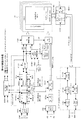
これに対して、図48の変形例では、外部クロックECLK1より高速のクロックICLK3を発生するクロック発生回路102とスイッチ回路SWとを設けて、通常動作状態では、外部クロックECLKに同期した内部クロックICLK2を生成しそれに同期して内部動作を制御し、内部でリフレッシュコマンドが発生した後は、外部クロックECLKより高速のクロックICLK3に同期した内部クロックICLK2を生成し、それに同期して内部動作を制御する。内部動作サイクルが外部クロックサイクルに追いついた後は、通常動作状態にもどり、外部クロックECLKに同期した内部クロックICLK2を生成する。
【0130】
このような内部動作タイミング用の内部クロックICLK2の切換のために、図48のメモリ回路では、リードコマンドRDとライトコマンドWRとリフレッシュコマンドREFの論理和をとるORゲート104と、その出力S1がHレベルになるタイミングとコマンド受付信号CMDENがHレベルになるタイミングとを比較する比較器103とを設けている。そして、コマンド受付信号CMDENのタイミングが早い間は、通常動作状態と判断され、動作切換信号OSWがLレベルになり、外部クロックECLKに同期したクロックECLK1が内部クロックICLK2として出力される。また、いずれかのコマンドの発生(ORゲート104の出力S1)のタイミングが早い間は、高速動作状態と判断され、動作切換信号OSWがHレベルになり、クロック発生回路102が生成する高速クロックICLK3が内部クロックICLK2として出力される。
【0131】
図49は、図48の変形例の動作タイミングチャート図である。この例では、リードコマンドRDが外部クロックECLK1に同期して入力する。それに応答して、コマンドレジスタ11がリードコマンドを保持すると共に出力する。また、リフレッシュタイマ21が所定の周期で発生するリフレッシュタイマ信号REFTMに応答して、リフレッシュコマンド発生回路20がリフレッシュコマンドREFを発生する。一方、制御回路14は、コマンドに対応する内部動作が終了するたびにコマンド受付信号CMDENを発生し、次のコマンドの受付を行う。
【0132】
そこで、比較器103は、コマンド受付信号CMDENの立ち上がりエッジと、リードコマンドRD、ライトコマンドWR及びリフレッシュコマンドREFの立ち上がりエッジ(又はHレベル開始時)とのタイミングを比較し、コマンド受付信号CMDENが早ければ動作切換信号OSWをLレベルにし通常動作モードとし、コマンドのタイミングが早ければ動作切換信号OSWをHレベルにして高速動作モードにする。つまり、この切換信号OSWに応じて、切換回路SWが外部クロックECLK1か高速クロックICLK3かを選択し、内部クロックICLK2として出力する。制御回路14は、この内部クロックICLK2に同期してメモリコア15を制御する。但し、リードデータの出力タイミングやライトデータの入力タイミングは、外部クロックECLK1に同期して行われる。
【0133】
図49の例では、リードコマンドRD-0A〜RD-A2までは通常動作状態であり、外部クロックECLK1に同期した内部クロックICLK2が生成されるが、リフレッシュコマンドREFが発生した後は、高速動作状態になり、高速クロックICLK3に同期した内部クロックICLK2が生成されている。やがて、リードコマンドRD-A7で内部動作サイクルが外部クロックサイクルに追いついて、リードコマンドRD-A8以降は、通常動作状態に戻っている。
【0134】
[第1の実施の形態の変形例2]
図50は、更に第1の実施の形態における別の変形例のメモリ回路を示す図である。この変形例のメモリ回路は、外部クロックが供給されないで、非同期で動作するダイナミックランダムアクセスメモリである。かかる非同期型のDRAMに、第1の実施の形態の動作が適用される。
【0135】
非同期型のDRAMは、外部コマンドを供給できる最小外部コマンド間隔がスペックに定められている。従って、メモリコントローラは、このスペックで定められた最小外部コマンド間隔より狭い時間間隔で外部コマンドを供給することはできない。そして、メモリ回路は、外部コマンドを受信してから内部のメモリ動作を行い、リードデータを出力する。リードコマンドを入力してからリードデータが出力されるまでのアクセスタイムが、スペックで定められている。従って、メモリコントローラは、外部コマンドを与えてから、上記アクセスタイムより遅れたタイミングでリードデータを取得する。リードデータを取得した時点で、メモリコントローラは、リードデータ取得を示す通知信号をメモリ回路に返信する。
【0136】
第1の実施の形態例は、通常動作時には、外部コマンドに応答して動作し、内部リフレッシュコマンドが発生した時は、外部コマンドサイクルより短く外部クロックに非同期の内部動作サイクルで動作する。従って、通常動作時は低速動作モードで動作し、内部リフレッシュコマンドが発生した時は高速動作モードで動作する。この動作を、非同期型DRAMに適用することは容易である。
【0137】
図50に示した変形例のメモリ回路は、図2のメモリ回路と比較すると、クロックバッファ10が設けられていない。そして、出力タイミング信号SOUTを生成する遅延回路100が新たに設けられている。この出力タイミング信号SOUTに応答してデータI/Oバッファ・レジスタ13が、リードデータを出力する。この遅延回路の遅延時間が、前述のアクセスタイムに対応する。それ以外の構成は、図2と同じである。
【0138】
制御回路14は、図4に示したものと同じであり、コマンドに対応した制御信号を発生してメモリアレイでの動作が終了すると、コマンド受付信号CMDENを生成し、次のコマンドを取得して対応する制御信号を発生する。そして、本変形例では、内部動作サイクルに対応するメモリアレイでの動作期間が、最小外部コマンド間隔より短く設計されている。その結果、通常動作では、外部コマンドの入力タイミングに同期して内部動作サイクルを繰り返すことができる。一方、内部でリフレッシュコマンドが発生した時は、外部コマンドの入力タイミングに同期せずに内部動作サイクルを連続して実行する。つまり、通常動作では、外部コマンドタイミングに同期して低速動作モードとなり、内部リフレッシュコマンドが発生すると、内部動作サイクルに従って高速動作モードとなる。そして、内部動作サイクルが外部コマンドタイミングに追いついたら、低速動作モードに戻る。
【0139】
図51は、変形例の動作を示すタイミングチャートである。図51(A)が通常動作時であり、外部コマンドのタイミングに同期した低速動作モードである。図示されるとおり、メモリアレイでの動作期間tmcaは、最小外部コマンド間隔tecmdよりも短くなるように設計されている。従って、内部動作サイクルであるメモリアレイ動作が、外部コマンドに同期して開始すると、次の外部コマンドが供給されるより前にその動作が終了する。メモリアレイ動作の終了に応答して、コマンド受付信号CMDENがHレベルに立ち上がるが、その時点では、次の外部コマンド(RD,WR)は供給されていない。所定の時間経過後に、次の外部コマンドが供給されると、それに応答して次のメモリアレイ動作が開始する。非同期型DRAMであっても、内部動作サイクルtmcaが最小外部コマンド間隔tecmdより短いので、通常動作では、内部動作サイクルが外部コマンドのタイミングに同期して繰り返すことができる。
【0140】
図51(B)は、内部リフレッシュコマンドREFが発生した時の外部コマンドタイミングに同期しない高速動作モードである。内部リフレッシュ動作が割り込まれたため、メモリアレイ動作が次の外部コマンドのタイミングまでに終了することができない。従って、次のメモリアレイ動作は、コマンド受付信号CMDENの立ち上がりに応答して連続して実行される。つまり、次の外部コマンドのタイミングを待つことなく、内部動作サイクルが連続して実行される。
【0141】
図52は、変形例における通常動作から内部リフレッシュコマンドが発生して高速動作モードに移行する場合の動作タイミングチャート図である。図5の動作タイミングチャート図からクロックCLK1を除いたものと同じである。最初のリードコマンドRD(A0)が発生した時は、既に前のメモリアレイ動作が終了してコマンド受付信号CMDENはHレベルになっている。従って、内部のメモリアレイ動作は、リードコマンドRD(A0)のタイミングに応答して開始する。これがサイクル1である。メモリアレイ動作は、前述のとおり、ワード線駆動(制御信号φWL)、センスアンプ活性化(制御信号φLE)、コラムゲート選択(制御信号φCL)、そしてプリチャージ(φPRE)で構成される。プリチャージ制御信号φPREが発生すると、コマンド受付信号CMDENがHレベルになる。
【0142】
図52の例では、最初のリード動作実行中にリフレッシュタイマREFTMがHレベルになり、内部リフレッシュのタイミングになったことを通知している。それに応答して、内部リフレッシュコマンドREF(Aa)が発生している。そして、最初のリードコマンドに対応するメモリアレイ動作が終了してコマンド受付信号CMDENがHレベルになった時点では、すでにリフレッシュコマンドREF(Aa)が発生しており、即座にリフレッシュコマンドに対応するリフレッシュ動作が開始する。これがサイクル2である。リフレッシュ動作は、コラムゲート選択が伴わないリード動作と同じである。
【0143】
更に、内部でリフレッシュ動作中に、次のリードコマンドRD(A1)が供給されているので、リフレッシュ動作が終了すると、続けて内部のリード動作が開始する。これがサイクル3である。
【0144】
図53は、変形例における低速動作モードと高速動作モードの動作タイミングチャート図である。この図は、図6からクロックCLK1を除いたものと同じである。即ち、クロック非同期のDRAMであり、外部コマンドCMDは、最小外部コマンド間隔以上の間隔で供給され、外部コマンドの供給から一定の遅延時間DELAY後にリードデータがDQ端子から出力される。図53の例では、最初の3つのリードコマンドRD-A0〜A2までは、外部コマンドに同期して内部動作が実行される低速動作モードである。そして、リフレッシュコマンドREFが発生した後のリードコマンドRD-A4〜A7までが、内部動作サイクルで動作が繰り返される高速動作モードである。内部動作サイクルが外部コマンドのタイミングに追いつくと、リードコマンドRD-A8以降は、外部コマンドに同期した低速動作モードに戻っている。
【0145】
以上のとおり、第1の実施の形態においては、外部コマンドが外部クロックに同期して供給されている場合でも、外部クロックに非同期に供給されている場合でも、内部動作サイクルを外部動作サイクルまたは最短外部コマンドサイクルより短くしておくことにより、内部で発生するリフレッシュコマンドを通常コマンド(リードやライト)の間に割り込ませて実行することができる。
【0146】
以上の実施の形態例をまとめると次の付記の通りである。
【0147】
(付記1)リフレッシュ動作を必要とするメモリ回路において、
メモリセルを有するメモリコアと
クロックに同期して供給されたコマンドを受信し内部に第1の内部コマンドを生成する第1の回路と、
前記クロックサイクルより大きい所定のリフレッシュサイクルで、内部にリフレッシュコマンドを生成する第2の回路と、
前記第1の内部コマンドに従って、対応する制御をクロック同期動作で実行し、前記リフレッシュコマンドが発行されると、当該リフレッシュコマンドに対応する制御と、前記第1の内部コマンドに対応する制御とをクロック非同期動作で順次実行するメモリ制御回路とを有することを特徴とするメモリ回路。
【0148】
(付記2)付記1において、
前記第1の回路は、前記供給コマンドに対応する前記第1の内部コマンドを保持し、
前記メモリ制御回路は、動作サイクル終了時に内部コマンド受付信号を生成し、当該内部コマンド受付信号に応答して、前記第1の内部コマンドまたはリフレッシュコマンドを受け付け、対応する制御を実行することを特徴とするメモリ回路。
【0149】
(付記3)付記2において、
前記メモリ制御回路は、前記第1の内部コマンドの受け付けに応答して、前記第1の回路のコマンドをリセットし、前記リフレッシュコマンドの受付に応答して、前記第2の回路のコマンドをリセットすることを特徴とするメモリ回路。
【0150】
(付記4)付記2において、
前記メモリ制御回路は、前記内部コマンド受付信号が発生した時に前記第1の内部コマンドまたはリフレッシュコマンドが発生していれば、当該コマンドに対応する制御をクロック非同期動作で実行し、
前記内部コマンド受付信号が発生した時に前記第1の内部コマンドまたはリフレッシュコマンドが発生していなければ、当該コマンドが発生するのを待ち、その後発生したコマンドに対応する制御を実行することを特徴とするメモリ回路。
【0151】
(付記5)付記1乃至4のいずれかにおいて、
更に、タイマー回路を有し、
前記第2の回路は、該タイマー回路が生成するリフレッシュタイミング信号に基づいて、前記リフレッシュコマンドを生成することを特徴とするメモリ回路。
【0152】
(付記6)集積回路装置において、
クロックに同期して供給されたコマンドを受信し内部に第1の内部コマンドを生成する第1の回路と、
前記クロックサイクルより大きい所定のサイクルで、内部に第2のコマンドを生成する第2の回路と、
前記第1の内部コマンドに従って、対応する制御をクロック同期動作で実行し、前記第2のコマンドが発行されると、当該第2のコマンドに対応する制御と、前記第1の内部コマンドに対応する制御とをクロック非同期動作で順次実行する内部回路とを有することを特徴とする集積回路装置。
【0153】
(付記7)リフレッシュ動作を必要とするメモリ回路において、
メモリセルを有するメモリコアと
M(M≧2)回の外部動作サイクルに対して、Mより多いN(M<N<2M)回の内部動作サイクルを有するメモリ制御回路と、
リフレッシュコマンドを発生するリフレッシュコマンド発生回路とを有し、
前記N回の内部動作サイクルは、前記外部動作サイクルに対応する外部コマンドを実行する第1の内部動作サイクルと、前記リフレッシュコマンドを実行する第2の内部動作サイクルとを有することを特徴とするメモリ回路。
【0154】
(付記8)付記7において、
更に、前記外部動作サイクルを画定する外部クロックに従って、前記内部動作サイクルを画定する内部クロックを生成する内部クロック発生回路を有し、
前記外部コマンドは、前記外部クロックに同期して入力され、前記内部動作サイクルは、前記内部クロックに同期していることを特徴とするメモリ回路。
【0155】
(付記9)付記8において、
リードデータの出力及びライトデータの入力は、前記外部クロックに同期して行われ、当該リードデータの前記メモリコアからの出力及びライトデータの前記メモリコアへの入力は、前記内部クロックに同期して行われることを特徴とするメモリ回路。
【0156】
(付記10)付記8において、
前記内部クロック発生回路は、前記M個の外部クロックに対して、前記N個の内部クロックを発生し、当該N個の内部クロックは、前記第1の内部動作サイクルを制御する第1の内部クロックと、前記第2の内部動作サイクルを制御する第2の内部クロックとを有し、
前記メモリ制御回路は、前記内部で発生するリフレッシュコマンドに応答して、前記第2の内部クロックに同期してリフレッシュ動作を実行することを特徴とするメモリ回路。
【0157】
(付記11)付記8において、
前記内部クロック発生回路は、前記M個の外部クロックに対して、前記N個の内部クロックを発生し、当該N個の内部クロックは、前記第1の内部動作サイクルを制御する第1の内部クロックと、前記第2の内部動作サイクルを制御する第2の内部クロックとを有し、
更に、所定のリフレッシュサイクルで生成されるリフレッシュタイマ信号と前記第2の内部クロックに応答して、前記リフレッシュコマンドを生成するリフレッシュコマンド発生回路を有し、
前記メモリ制御回路は、前記リフレッシュコマンドに応じてリフレッシュ動作を実行することを特徴とするメモリ回路。
【0158】
(付記12)付記10において、
更に、前記外部クロックが入力されないパワーダウンモードを有し、
当該パワーダウンモード時には、前記メモリ制御回路は、所定のリフレッシュサイクルで生成されるリフレッシュタイマ信号に応答して、前記内部クロックにかかわらず、前記リフレッシュ動作を実行することを特徴とするメモリ回路。
【0159】
(付記13)付記11において、
更に、前記外部クロックが入力されないパワーダウンモードを有し、
前記リフレッシュコマンド発生回路は、前記リフレッシュタイマ信号に応答して、前記第2の内部クロックにかかわらず、前記リフレッシュコマンドを生成することを特徴とするメモリ回路。
【0160】
(付記14)付記7,8,9のいずれかにおいて、
前記メモリ制御回路は、前記リフレッシュコマンドに対応する制御を、複数の第2の内部動作サイクルに分割して行うことを特徴とするメモリ回路。
【0161】
(付記15)付記14において、
前記複数の第2の内部動作サイクルは、所定数の連続する第1の内部動作サイクルを間に挟んでいることを特徴とするメモリ回路。
【0162】
(付記16)付記14において、
前記複数の第2の内部動作サイクルは、所定数の連続する第1の内部動作サイクルを間に挟んでいて、前記第2の内部動作サイクルは、前記第1の内部動作サイクルより短いことを特徴とするメモリ回路。
【0163】
(付記17)付記14において、
前記メモリコアは、被リフレッシュメモリセルのデータを一時的に保持するデータレジスタを有し、
前記メモリ制御回路は、最初の第2の内部動作サイクルで前記被リフレッシュメモリセルのデータを読み出して前記データレジスタに保持し、次の第2の動作サイクルで前記データレジスタ内に保持されたデータを前記被リフレッシュメモリセルに再書き込みすることを特徴とするメモリ回路。
【0164】
(付記18)付記17において、
前記最初の第2の内部動作サイクルにおけるアドレスと、後続する第1の内部動作サイクルにおけるアドレスが一致する場合は、当該後続する第1の内部動作サイクルにおいて、前記データレジスタが保持するデータに従って、読み出しまたは再書き込みが行われることを特徴とするメモリ回路。
【0165】
(付記19)クロックに同期して動作する集積回路装置において、
M(M≧2)回の外部動作サイクルに対して、Mより多いN(M<N<2M)回の内部動作サイクルを有する内部回路を有し、
前記N回の内部動作サイクルは、前記外部動作サイクルに対応する外部コマンドを実行する第1の内部動作サイクルと、内部コマンドを実行する第2の内部動作サイクルとを有することを特徴とする集積回路装置。
【0166】
(付記20)付記19において、
更に、前記外部動作サイクルを画定する外部クロックに従って、前記内部動作サイクルを画定する内部クロックを生成する内部クロック発生回路を有し、
前記外部コマンドは、前記外部クロックに同期して入力され、前記内部動作サイクルは、前記内部クロックに同期していることを特徴とする集積回路装置。
【0167】
(付記21)リフレッシュ動作を必要とするメモリ回路において、
メモリセルを有するメモリコアと
M(M≧2)回の外部動作サイクルに対して、Mより多いN(M<N<2M)回の内部動作サイクルを有するメモリ制御回路と、
リフレッシュコマンドを発生するリフレッシュコマンド発生回路とを有し、
前記N回の内部動作サイクルは、前記外部動作サイクルに対応する外部コマンドを実行する第1の内部動作サイクルと、前記リフレッシュコマンドを実行する第2の内部動作サイクルとを有し、
前記リフレッシュコマンド発生回路は、前記外部コマンドに応じて前記リフレッシュコマンドを発生することを特徴とするメモリ回路。
【0168】
(付記22)付記21において、
前記外部クロックの周波数が、前記外部動作サイクルよりも高く、当該外部クロックに従って前記内部動作サイクルを画定する内部クロックを生成する内部クロック発生回路を有し、
前記外部コマンドは、前記外部動作サイクル以上のサイクルで供給され、更に、前記外部クロックに同期して入力されることを特徴とするメモリ回路。
【0169】
(付記23)付記22において、
前記リフレッシュコマンド発生回路は、所定数の前記外部クロックに同期して入力される外部コマンドの組み合わせに応じて、前記リフレッシュコマンドの発生を許可することを特徴とするメモリ回路。
【0170】
(付記24)付記22において、
前記リフレッシュコマンド発生回路は、所定数の連続する前記外部クロックのうち何れかの外部クロックに同期して前記外部コマンドが入力されない時に、前記リフレッシュコマンドの発生を許可することを特徴とするメモリ回路。
【0171】
(付記25)付記22において、
前記外部コマンドの周波数が、前記外部動作サイクルのL倍の場合に、
前記リフレッシュコマンド発生回路は、前記L個の連続する外部クロックのうち何れか(L−1)個の外部クロックに同期して前記外部コマンドが入力されない時に、前記リフレッシュコマンドの発生を許可し、更に、前記M個の外部動作サイクル内において、前記(L−1)個の外部クロックの組み合わせが循環することを特徴とするメモリ回路。
【0172】
(付記26)付記22において、
前記外部コマンドの周波数が、前記外部動作サイクルのL倍の場合に、
更に、最新の前記L個の外部クロックにおける前記外部コマンドを保持し、該保持した外部コマンドに従って、対応する内部コマンドを発生する内部コマンドレジスタを有し、
前記内部コマンドレジスタは、前記N回の内部動作サイクルの間での所定のサイクルにおいて、前記L個の保持した外部コマンドのうち、一部のサイクルの保持外部コマンドを無視して、前記内部コマンドを発生することを特徴とするメモリ回路。
【0173】
(付記27)付記26において、
前記リフレッシュコマンド発生回路は、前記内部コマンドレジスタが発生する内部コマンドに応じて、前記リフレッシュコマンドの発生を許可することを特徴とするメモリ回路。
【0174】
(付記28)付記26において、
前記リフレッシュコマンド発生回路は、前記内部コマンドレジスタが発生する内部コマンドが存在しない時に、前記リフレッシュコマンドの発生を許可することを特徴とするメモリ回路。
【0175】
(付記29)付記23乃至28のいずれかにおいて、
前記リフレッシュコマンド発生回路は、所定のタイミングで発生するリフレッシュタイマ信号の発生に応答して、前記リフレッシュコマンド発生許可状態の時に、前記リフレッシュコマンドを発生することを特徴とするメモリ回路。
【0176】
(付記30)リフレッシュ動作を必要とするメモリ回路において、
メモリセルを有するメモリコアと
外部クロックに同期して供給されたコマンドを受信し内部に第1の内部コマンドを生成する第1の回路と、
前記外部クロックサイクルより大きい所定のリフレッシュサイクルで、内部にリフレッシュコマンドを生成する第2の回路と、
前記外部クロックに同期した第1の内部動作サイクルと、当該第1の内部動作サイクルより短い第2の内部動作サイクルとを有し、前記第1の内部コマンドに対応する制御を前記第1の内部動作サイクルで実行し、前記リフレッシュコマンドが発行された時、当該リフレッシュコマンドに対応する制御と、前記第1の内部コマンドに対応する制御とを、前記第2の内部動作サイクルで順次実行するメモリ制御回路とを有することを特徴とするメモリ回路。
【0177】
(付記31)付記30において、
更に、前記第1の内部コマンドまたはリフレッシュコマンドの発生タイミングより内部動作の終了タイミングが早い間は、前記メモリ制御回路は、前記第1の内部動作サイクルで対応する制御を実行し、前記内部動作の終了タイミングより前記第1の内部コマンドまたはリフレッシュコマンドの発生タイミングが早い間は、前記メモリ制御回路は、前記第2の内部動作サイクルで対応する制御を実行することを特徴とするメモリ回路。
【0178】
(付記32)クロックに同期して動作する集積回路装置において、
外部から受信したコマンドに従い内部に第1の内部コマンドを生成する第1の回路と、
外部動作サイクルより長いサイクルで内部に第2の内部コマンドを生成する第2の回路と、
前記外部動作サイクルに同期して内部動作を実行する第1の内部動作サイクルと、当該第1の内部動作サイクルより短いサイクルで内部動作を実行する第2の内部動作サイクルとを有する内部回路とを有し、
前記内部回路は、通常は第1の内部動作サイクルで前記第1の内部コマンドに対応する動作を実行し、該第2の内部コマンドが発生したら所定の期間該第2の動作サイクルで前記第1及び第2の内部コマンドに対応する動作を実行することを特徴とする集積回路装置。
【0179】
(付記33)最小外部コマンドサイクル以上の間隔で供給される外部コマンドを受信するメモリ装置において、
メモリセルを有し、前記最小外部コマンドサイクルより短い内部動作サイクルを有するメモリコアと、
前記セルをリフレッシュするリフレッシュコマンドを内部で生成するリフレッシュコマンド生成回路と、
前記外部コマンドとリフレッシュコマンドとを受信し、前記メモリコアを制御する制御回路とを有し、
前記制御回路は、前記制御回路が前記外部コマンド及びリフレッシュコマンドをコマンド受付期間の開始時に受信しない場合は、前記メモリコアが前記外部コマンドまたはリフレッシュコマンドを受信したときに内部動作サイクルを実行開始し、前記制御回路が前記外部コマンドまたはリフレッシュコマンドをコマンド受付期間の開始時に受信している場合は、前記メモリコアが前記コマンド受付期間に入った直後に前記内部動作サイクルを実行開始するよう制御することを特徴とするメモリ装置。
【0180】
(付記34)付記33において、
前記制御回路が前記外部コマンド及びリフレッシュコマンドをコマンド受付期間の開始時に受信しない場合、前記外部コマンドまたはリフレッシュコマンドの受信タイミングと前記コマンド受付期間の開始タイミングとの間に所定の期間を有することを特徴とするメモリ装置。
(付記35)付記33において、
前記制御回路が前記外部コマンドまたはリフレッシュコマンドをコマンド受付期間の開始時に受信している間は、前記複数の内部動作サイクルが連続して実行されることを特徴とするメモリ装置。
(付記36)付記33において、
外部クロックが供給されない非同期型メモリであることを特徴とするメモリ装置。
(付記37)付記33において、
前記外部コマンドは読み出しコマンドまたは書き込みコマンドであることを特徴とするメモリ装置。
(付記38)付記33において、
前記リフレッシュコマンド生成回路は、通常動作モードとパワーダウンモードの両方において前記リフレッシュコマンドを生成することを特徴とするメモリ装置。
(付記39)付記33において、
前記内部動作サイクルは、ワード線の活性化と、ビット線電圧の増幅と、前記ワード線の非活性化とを有することを特徴とするメモリ装置。
(付記40)付記33において、
前記制御回路は、ビット線のプリチャージのためのプリチャージ信号に応答して生成されるコマンド受付信号を受信することを特徴するメモリ装置。
(付記41)付記40において、
前記コマンド受付信号の変化が前記コマンド受付期間の開始に対応することを特徴とするメモリ装置。
(付記42)付記33において、
更に、前記外部コマンドを記憶し、前記外部コマンドを制御回路に供給するコマンドレジスタを有することを特徴とするメモリ装置。
(付記43)付記42において、
前記コマンドレジスタは、前記内部動作サイクルの開始時にリセットされることを特徴とするメモリ装置。
【0181】
以上、本発明の保護範囲は、上記の実施の形態例に限定されるものではなく、特許請求の範囲に記載された発明とその均等物にまで及ぶものである。
【0182】
【発明の効果】
以上、本発明によれば、クロック同期型の集積回路において、外部からの命令に対応しない所定の内部動作サイクルを自発的に生成して実行することができるので、外部コントローラの制御を容易にすることができる。
【0183】
また、本発明によれば、リフレッシュを必要とするメモリ回路において、通常動作状態でも、外部コントローラからリフレッシュコマンドを与えることなく、内部で自動的にリフレッシュ動作サイクルを生成することができる。
【図面の簡単な説明】
【図1】従来のメモリ回路の構成図である。
【図2】第1の実施の形態例におけるメモリ回路の全体構成図である。
【図3】クロック同期動作とクロック非同期動作を示す図である。
【図4】メモリ制御回路14の構成例を示す図である。
【図5】リフレッシュコマンドが発生した時のクロック同期動作からクロック非同期動作に移行する場合を示すタイミングチャート図である。
【図6】第1の実施の形態例におけるクロック同期動作とクロック非同期動作とを示すタイミングチャート図である。
【図7】より低速の外部クロックの場合のクロック同期動作とクロック非同期動作とを示すタイミングチャート図である。
【図8】更に低速の外部クロックの場合のクロック同期動作とクロック非同期動作とを示すタイミングチャート図である。
【図9】外部クロックCLK1のサイクルに比較して内部動作サイクルが2倍長い場合のクロック同期動作とクロック非同期動作とを示すタイミングチャート図である。
【図10】第2の実施の形態例におけるメモリ回路の構成図である。
【図11】第2の実施の形態例のメモリ回路の動作タイミングチャート図である。
【図12】リードコマンドとライトコマンドとが混在する場合の動作タイミングチャート図である。
【図13】クロック発生回路の回路図である。
【図14】クロック発生回路の動作タイミングチャート図である。
【図15】リフレッシュコマンド発生回路とその動作タイミングチャートとを示す図である。
【図16】第3の実施の形態例におけるメモリ回路の構成図である。
【図17】第3の実施の形態例のリフレッシュ動作を説明する図である。
【図18】第3の実施の形態例のリフレッシュ動作を説明する図である。
【図19】第3の実施の形態例の動作タイミングチャート図である。
【図20】第3の実施の形態例に適用するクロック発生回路を示す図である。
【図21】クロック発生回路の動作タイミングチャート図である。
【図22】第3の実施の形態例に適用するリフレッシュコマンド発生回路とその動作タイミングチャートを示す図である。
【図23】パワーダウン状態でのリフレッシュコマンド発生回路とその動作タイミングチャートを示す図である。
【図24】第4の実施の形態例におけるメモリ回路を示す図である。
【図25】第4の実施の形態例の動作タイミングチャート図である。
【図26】第4の実施の形態例の動作タイミングチャート図である。
【図27】第4の実施の形態例の動作タイミングチャート図である。
【図28】第4の実施の形態例の動作タイミングチャート図である。
【図29】第4の実施の形態例に適用されるクロック発生回路を示す図である。
【図30】図29のクロック発生回路の動作タイミングチャート図である。
【図31】第4の実施の形態例に適用される別のクロック発生回路を示す図である。
【図32】図29のクロック発生回路の動作タイミングチャート図である。
【図33】第4の実施の形態例に適用されるリフレッシュコマンド発生回路とその動作を示す図である。
【図34】第4の実施の形態例における別のコマンドレジスタ回路を示す図である。
【図35】図34のコマンドレジスタ回路を使用した場合のメモリ回路の動作タイミングチャート図である。
【図36】図34のコマンドレジスタ回路を使用した場合のメモリ回路の動作タイミングチャート図である。
【図37】図34のコマンドレジスタを利用した場合のクロック発生回路の図である。
【図38】図37のクロック発生回路の動作タイミングチャート図である。
【図39】第5の実施の形態例におけるメモリ回路の構成図である。
【図40】図39の信号の流れを示す図である。
【図41】図39の動作タイミングチャート図である。
【図42】第5の実施の形態例における別のコマンドレジスタ回路の図である。
【図43】図42の信号の流れを示す図である。
【図44】図42の動作タイミングチャート図である。
【図45】別のクロック発生回路が適用される外部動作サイクルと内部動作サイクルとの関係を示す図である。
【図46】別のクロック発生回路を示す図である。
【図47】図46のクロック発生回路の動作タイミングチャート図である。
【図48】第1の実施の形態における変形例のメモリ回路を示す図である。
【図49】図48の変形例の動作タイミングチャート図である。
【図50】第1の実施の形態における別の変形例のメモリ回路を示す図である。
【図51】変形例の動作を示すタイミングチャートである。
【図52】変形例における通常動作から内部リフレッシュコマンドが発生して高速動作モードに移行する場合の動作タイミングチャート図である。
【図53】変形例における低速動作モードと高速動作モードの動作タイミングチャート図である。
【符号の説明】
11 コマンドデコーダ、コマンドレジスタ(11B)
12 アドレスバッファ、アドレスレジスタ
13 データ入出力バッファ、データ入出力レジスタ
14 制御回路、メモリ制御回路
15 メモリコア
20 リフレッシュコマンド発生回路
21 リフレッシュタイマ
35 クロック発生回路
50 アドレス比較器
ECLK 外部クロック
ECLK1 外部クロック同期のクロック
ICLK1,2,3 内部クロック
ICLK-L 出力ラッチクロック
CMD 外部コマンド
RD,WR 内部コマンド、リードコマンド、ライトコマンド
REF-CLK リフレッシュクロック
REFTM リフレッシュタイマ信号
REF リフレッシュコマンド[0001]
BACKGROUND OF THE INVENTION
The present invention relates to a memory circuit such as a dynamic random access memory that requires a refresh operation periodically, and performs a refresh operation automatically without requiring an external refresh command. Correspondingly, the present invention relates to a memory circuit capable of performing internal operation at high speed. Furthermore, the present invention relates to an integrated circuit device capable of automatically generating and executing a command internally in addition to an external command.
[0002]
[Prior art]
Dynamic random access memory (DRAM) is widely used as a large capacity memory. Since DRAM is a volatile memory, a refresh operation is necessary.
[0003]
FIG. 1 is a configuration diagram of a conventional memory circuit. A conventional memory circuit includes a
[0004]
As described above, a clock synchronous DRAM (SDRAM) has auto-refresh and self-refresh as refresh operations. Auto-refresh is a refresh operation that is periodically performed during normal read / write operations, and is executed by an auto-refresh command supplied from the outside. That is, when an auto-refresh command is input from the outside, the
[0005]
On the other hand, the self-refresh is a refresh operation performed by the memory device by itself in response to the refresh timing automatically generated by the internal oscillator OSC during the power down mode state. In the power down mode state, since commands (reading and writing) are not supplied from the outside, the
[0006]
As described above, since the command is supplied from the outside during the normal operation state, the refresh command is also supplied from the outside, and the refresh operation is executed in response thereto. Further, since no command is supplied from the outside during the power-down state, a refresh timing is automatically generated inside and a refresh operation is executed.
[0007]
[Problems to be solved by the invention]
As described above, in the conventional memory circuit, the memory controller that controls the memory circuit needs to control the refresh timing during the normal operation state. That is, the memory controller is equipped with a timer, and it is necessary to issue an auto-refresh command to the memory circuit every time the refresh timing comes. Therefore, the memory controller has a problem that the control of the memory circuit becomes complicated.
[0008]
In the conventional memory circuit, the
[0009]
In the latter case, that is, it is not preferable to reject the command from the memory controller, the general memory circuit executes the internal operation as it is in response to the supplied command as in the former case. Therefore, when a refresh command is issued spontaneously in the memory circuit in the normal operation state and the refresh operation is executed, the refresh operation is disturbed by the command supplied during the operation. Further, if the command supplied as in the latter case is rejected, the control of the memory controller becomes more complicated.
[0010]
SUMMARY OF THE INVENTION An object of the present invention is to provide a memory circuit that can automatically perform a refresh operation without receiving a refresh command from a memory controller.
[0011]
Another object of the present invention is to automatically perform a refresh operation without requiring an external refresh command during normal operation, and further, in response to an external normal command, the internal operation can be performed at high speed. It is an object of the present invention to provide a memory circuit that can execute an operation.
[0012]
Another object of the present invention is to provide an integrated circuit device capable of automatically issuing an internal command in addition to receiving an external command and executing the internal command without disturbing the operation corresponding to the external command. Is to provide.
[0013]
[Means for Solving the Problems]
In order to achieve the above object, according to a first aspect of the present invention, in an integrated circuit device, a first circuit that receives a command in synchronization with a clock and generates a first internal command therein, And a second circuit for generating a second internal command in a cycle. Then, the internal circuit executes the corresponding internal operation in accordance with the first internal command in the clock synchronous operation, and when the second internal command is issued, the internal operation corresponding to the second internal command, The internal operation corresponding to the internal command is sequentially executed by clock asynchronous operation.
[0014]
In a more preferred embodiment, the integrated circuit device is a memory circuit that requires a refresh operation, the first internal command is a read or write command, and the second internal command is a refresh command, The internal circuit is a memory control circuit. That is, according to this embodiment, in the normal state, the memory control circuit executes the control operation corresponding to the first internal command in the clock synchronous operation according to the command received in the clock synchronous manner. When a refresh command is generated as a second internal command internally, the memory control circuit sequentially executes the refresh command and a control operation corresponding to the first internal command in a clock asynchronous operation. Eventually, when the internal operation cycle catches up with the external operation cycle, the memory control circuit executes the control operation corresponding to the first internal command again in the clock synchronous operation.
[0015]
In another preferred embodiment, the integrated circuit device further comprises an internal clock generation circuit for generating a first internal clock synchronized with an external clock and a second internal clock faster than the external clock, Normally, the circuit executes an internal operation corresponding to the first internal command in synchronization with the first internal clock, and when the second internal command is generated, the circuit corresponds to the second internal command. The internal operation and the internal operation corresponding to the first internal command are executed in synchronization with the second internal clock.
[0016]
The first aspect of the present invention can also be applied to an asynchronous memory circuit. In this case, the shortest external command cycle in which supply of an external command is permitted is defined by the specification, and the memory control circuit has an internal operation cycle shorter than the shortest external command cycle. The memory control circuit executes an internal operation in response to an external command during a normal operation, and continuously executes an internal operation in an internal operation cycle when an internal refresh command is generated.
[0017]
According to a second aspect of the present invention, in a clock synchronous integrated circuit device, N (M <N <2M) internal operation cycles greater than M are provided for M (M ≧ 2) external operation cycles. It is characterized by having. Then, M internal operation cycles corresponding to a maximum of M external commands and at least one internal operation cycle corresponding to an internal command not corresponding to the external command are assigned to M external operation cycles. It is done. That is, by making the internal operation cycle slightly shorter than the external operation cycle, it is possible to execute an internal command that may occur within an expanded operation cycle consisting of M external operation cycles.
[0018]
The more preferred embodiment of the second aspect is applied to a memory circuit that requires a refresh operation. In that case, when a refresh command is generated internally during an expansion operation cycle consisting of M operation cycles, the refresh operation is executed using (NM) internal operation cycles. This (N−M) times is the difference between the number N of internal operation cycles and the number M of external operation cycles in the expansion operation cycle. Moreover, by setting the latency from external command input to read data output to multiple clocks, it is possible to output read data continuously to external memory controllers in response to continuous external commands. Become.
[0019]
In the memory circuit of the preferred embodiment, an internal clock generation circuit for generating N internal clocks is provided during an expansion operation cycle composed of M external clocks. The external command is input in synchronization with the external clock (or with a predetermined phase difference), and the internal command is generated in synchronization with the internal clock. The read data is output from the memory core in synchronization with the delayed internal clock, and output from the data output terminal in synchronization with the external clock. Similarly, the write data is input from the data input terminal in synchronization with the external clock, and input to the memory core in synchronization with the internal clock. Accordingly, the phase difference between the external clock and the internal clock is absorbed by the command / data input / output circuit section.
[0020]
Another preferred embodiment of the second aspect is similarly applied to a memory circuit that requires a refresh operation. In that case, when a refresh command is generated internally during an expansion operation cycle consisting of M operation cycles, the refresh operation is executed using (NM) internal operation cycles. Further, the refresh operation can be executed by being divided into a plurality of internal operation cycles. By doing so, the latency (access time) from the input of an external command to the output of read data can be shortened, and high-speed operation can be ensured.
[0021]
In another preferred embodiment described above, when the refresh operation is divided into the word line drive operation and the rewrite operation to the memory cell, the refresh address (row address) during the refresh operation and the subsequent read or write operation If the address (row address) matches, the data read and held during the first refresh operation is used as read data for subsequent read or write operations. Thereby, even if the data in the memory cell is destroyed during the first refresh operation, the subsequent operation is not hindered.
[0022]
According to a third aspect of the present invention, in the second aspect, when the external clock for controlling the input of the external command is shorter than the external operation cycle, the external command is input in synchronization with the external clock. In response, a second internal operation cycle is generated. Therefore, when the third aspect is applied to the memory circuit, the refresh command generation circuit generates a refresh command according to the input status of the external command.
[0023]
According to the third aspect, even the integrated circuit device or the memory circuit mounted in the high-speed clock system can independently generate and execute the second internal operation cycle.
[0024]
DETAILED DESCRIPTION OF THE INVENTION
Embodiments of the present invention will be described below with reference to the drawings. However, such an embodiment does not limit the technical scope of the present invention. Although the following embodiments will be described by taking a memory circuit as an example, the present invention is not limited to the memory circuit and can be applied to a general integrated circuit device.
[0025]
[First Embodiment]
FIG. 2 is an overall configuration diagram of the memory circuit in the first embodiment. The same reference numbers are given to the same elements as in FIG. An external clock CLK supplied from the outside is input to the
[0026]
In the memory circuit in the first embodiment, the command decoder /
[0027]
The
[0028]
For this purpose, the
[0029]
FIG. 3 is a diagram illustrating a clock synchronous operation and a clock asynchronous operation. FIG. 3A illustrates the clock synchronization operation. The commands RD and WR are input and generated in synchronization with the clock CLK1, and are held by the
[0030]
The
[0031]
In a normal synchronous DRAM, taking into account variations due to manufacturing processes and the like, even if the memory cell array operation period tmca is repeated in synchronization with the clock CLK1, a command waiting time t1 is provided during the memory cell array operation period tmca. . Therefore, as shown in FIG. 3A, even when the memory cell array operation period tmca ends and the command acceptance signal CMDEN is generated, a new command is not input until after the command waiting time t1. Then, after a new command is input, the internal command is taken into the
[0032]
Next, FIG. 3B shows a clock asynchronous operation. The commands RD and WR are held in synchronization with the clock CLK1, or a refresh command REF (not shown) is generated asynchronously. Since the internal commands RD, WR, and REF have already been generated at the end of the memory cell array operation period tmca, the
[0033]
When the clock asynchronous operation is performed, the command waiting time t1 does not exist. Therefore, even if the memory cell array operation is started after the phase of the clock CLK1, the memory cell array operation is performed by executing a plurality of commands in the minimum operation cycle. Eventually, it can catch up with the phase of clock CLK1.
[0034]
As described above, the clock synchronous operation is a normal operation, and the clock asynchronous operation corresponds to a high-speed operation. Switching between the normal operation and the high-speed operation can be easily performed by taking the logical product of the internal command held in the
[0035]
When the memory cell array starts an operation corresponding to the command, the command reception signal CMDEN is reset and the internal command of the
[0036]
FIG. 4 is a diagram illustrating a configuration example of the
[0037]
Further, the
[0038]
FIG. 5 is a timing chart showing a case where the clock synchronous operation is shifted to the clock asynchronous operation when the refresh command is generated. It is assumed that the memory cell array repeats the normal operation synchronized with the clock until the rising edge C1 of the clock CLK1. Therefore, the command reception signal CMDEN is generated before the rising edge C1 of the clock. Further, it is assumed that the refresh timer signal REFTM is generated before the rising edge C1 of the clock.
[0039]
When the refresh timer signal REFTM is generated before the
[0040]
The internal command RD (A0) (read command) generated at the rising edge C1 is input to the
[0041]
At this time, since the refresh command REF is generated, the
[0042]
When the refresh operation ends, the command acceptance signal CMDEN is generated again. At this time, the internal command RD (A1) is already held in the
[0043]
Similarly, internal commands generated in synchronization with the clock edge are sequentially executed in a clock asynchronous operation. Since the clock asynchronous operation is a high-speed operation without a waiting time, the internal operation cycle eventually catches up with the cycle of the clock CLK1, and the command reception signal CMDEN is earlier than the phase of the rising edge of the clock CLK1. As a result, the internal operation cycle becomes a clock synchronous operation synchronized with the clock CLK1 with the waiting time t1 in between.
[0044]
FIG. 6 is a timing chart showing a clock synchronous operation and a clock asynchronous operation (high-speed operation) in the first embodiment. FIG. 6 illustrates the operation of FIG. 5 with more operating cycles. The command CMD from the outside is supplied in synchronization with the clock CLK1, and the internal command is held by the
[0045]
Initially, the internal operation cycle RD0-2 is executed in synchronization with the clock CLK1. If the refresh timer generates the refresh timer signal REFTM during the internal operation cycle RD1, the internal refresh command REF is output after a certain delay. When the internal operation cycle RD2 ends, an internal operation cycle according to the refresh command REF starts immediately. After that, the operation shifts to the clock asynchronous operation, and the internal operation cycle RD3-7 becomes high-speed operation. Eventually, when the internal operation cycle catches up with the cycle of the clock CLK1, the internal operation cycle RD8 and later becomes the clock synchronous operation again.
[0046]
That is, all the read commands that are continuously input are input and held, a refresh operation cycle is interrupted as necessary, and the read command held in the clock asynchronous high speed operation is executed. Therefore, the read data is continuously output to the data output terminal DQ, and the memory controller does not see the internal refresh operation, and seems to perform normal continuous reading.
[0047]
FIG. 7 is a timing chart showing a clock synchronous operation and a clock asynchronous operation (high-speed operation) in the case of a slower external clock. In this case, the internal high-speed operation (clock asynchronous operation) cycle is considerably shorter than the clock CLK1. Therefore, the clock asynchronous operation starts from the refresh operation cycle REF after the generation of the refresh command REF, but the high-speed operation is up to the next read operation cycle RD3 and thereafter the clock synchronous operation. That is, the period until the internal operation cycle catches up with the cycle of the clock CLK1 after execution of the refresh operation is shortened.
[0048]
FIG. 8 is a timing chart showing a clock synchronous operation and a clock asynchronous operation (high-speed operation) in the case of a lower-speed external clock. In this case, the refresh operation is performed asynchronously after the third read operation cycle RD, but the refresh operation ends before the rising edge of the next clock CLK1, and the clock synchronous operation is performed from the next read operation cycle. Return to.
[0049]
In any of the cases of FIGS. 6, 7, and 8, a continuous command is being processed during normal operation by controlling the internal circuit so that read data is output to the data output terminal DQ after two clocks from the input of the external command. Even if the refresh operation is interrupted, read data can be continuously output without any problem.
[0050]
FIG. 9 is a timing chart showing a clock synchronous operation and a clock asynchronous operation (high-speed operation) when the internal operation cycle is twice as long as the cycle of the external clock CLK1. This is an example in which the clock CLK1 in the system in which the memory device is mounted is high speed, while the internal operation of the device is low speed. In this case, the command from the outside is not allowed to be supplied continuously in synchronization with the external clock CLK1 due to specifications. Therefore, at the fastest speed, an external command is supplied in synchronization with the rising edge of the odd-numbered or even-numbered clock. Even in this case, as shown in FIG. 9, it is possible to insert a refresh operation cycle by using the waiting time t1 between the internal operation cycles in the same manner as in FIG. However, in the case of FIG. 9, read data is output to the data output terminal DQ after 4 clocks from the input of the external command.
[0051]
In some cases, after a command is input in synchronization with an odd-numbered clock, the command is supplied in synchronization with an even-numbered clock. However, even in that case, the command is not supplied in synchronization with the continuous clock. Therefore, in this case, there are two clock cycles between commands, and there is no trouble in inserting an internal refresh operation cycle.
[0052]
In the first embodiment, the refresh timer signal REFTM has a frequency that is, for example, two digits lower than the clock CLK. Therefore, the refresh timer signal REFTM is generated once for several hundred clocks CLK. As a result, an internal operation cycle is obtained by adding one cycle to several hundred cycles with respect to several hundred external cycles. It is not necessary to assign two internal operation cycles, that is, an internal operation cycle and a refresh operation cycle, to all external operation cycles, and high-speed operation is guaranteed in normal operation.
[0053]
[Second Embodiment]
The second embodiment is a memory circuit that executes a command in an internal operation cycle shorter than an external operation cycle. In a memory circuit that requires a refresh operation, the memory control circuit has N (M <N <2M) internal operation cycles greater than M for M (M ≧ 2) external operation cycles. The external command is input in synchronization with the external operation cycle. Also, read data output and write data input are performed in synchronization with the external operation cycle. On the other hand, the N internal operation cycles have a first internal operation cycle for executing an external command corresponding to the external operation cycle and a second internal operation cycle for executing a refresh command. When a refresh command is issued internally, a refresh operation is performed using the second internal operation cycle.
[0054]
As described above, the memory circuit according to the second embodiment generates N internal operation cycles more than M times within the expanded operation cycle including M external operation cycles, and (N−M) A refresh operation corresponding to a refresh command automatically generated internally is executed using the internal operation cycle. However, since commands and write data are input and read data are output in synchronization with the external operation cycle, it appears to the memory controller that the memory circuit is operating in synchronization with the external operation cycle. In addition, if N internal operation cycles are performed one cycle or several cycles more than M times, read data is continuously transmitted in synchronization with an external operation cycle with a predetermined read latency delay with respect to continuous read commands. Can be output.
[0055]
In the following embodiment, a case where M = 7 and N = 8 will be described.
[0056]
FIG. 10 is a configuration diagram of a memory circuit in the second embodiment. The same reference numbers are given to the same parts as in FIG. FIG. 11 is an operation timing chart thereof. Compared with FIG. 2, the memory circuit of FIG. 10 has a clock generation circuit that generates a clock ECLK1 synchronized with the external clock and internal clocks ICLK1 to ICLK3 and REF-CLK for controlling the internal operation cycle from the external clock ECLK. It differs in that it is provided. As shown in FIG. 11, the internal clock defines eight internal operation cycles that occur for seven external operation cycles. Therefore, the period of the internal clock is slightly shorter than the period of the external clock.
[0057]
In the clock generated by the
[0058]
Therefore, in the memory circuit of FIG. 10, the external command CMD is input to the
[0059]
On the other hand, the
[0060]
The timing chart of FIG. 11 shows a case where read commands Read-0 to Read12 are supplied as external commands in synchronization with the external clock ECLK. A cycle composed of seven external clocks ECLK is referred to as an expansion operation cycle. For this expansion operation cycle, seven internal clocks ICLK1 and one refresh clock REF-CLK are generated.
[0061]
First, in synchronization with the external clock ECLK1, an external command is input to the
[0062]
In the example of FIG. 11, the second internal operation cycle in the expansion operation cycle is assigned to the refresh operation cycle. Therefore, the refresh clock REF-CLK is generated as the second internal clock. In response to the refresh timer signal REFTM generated every refresh cycle by the
[0063]
Therefore, the internal operation cycle after the refresh operation is interrupted is considerably delayed compared to the external operation cycle (external clock ECLK cycle), but the internal operation cycle is 1/8 of the external clock cycle. Because it is short, the internal operation cycle approaches the external clock cycle little by little and catches up at the end of the extended operation cycle.
[0064]
FIG. 12 is an operation timing chart when a read command and a write command are mixed. In this case, as in the case of FIG. 11, there are eight internal operation cycles for seven external clocks. The write data D2 is input in synchronization with the external clock, and the write operation is executed in synchronization with the internal operation cycle. Since the read latency is 2, the next write command Write-2 is supplied 4 clocks after the read command Read-1. This prevents the read data Q1 and the write data D2 from conflicting at the input / output terminal DB.
[0065]
FIG. 13 is a circuit diagram of the clock generation circuit. FIG. 14 is an operation timing chart thereof. The
[0066]
The output N1 of the pulse
[0067]
Accordingly, eight internal clocks N1 to N8 having a phase shift obtained by dividing one cycle of the external clock ECLK into eight equal parts are generated as outputs of the variable delay elements. The internal clocks N1 to N8 are selected by the multiplexer 38 in accordance with the selection signals S1 to S8 output from the
[0068]
The second clock is removed from the internal clock N10 by the NOR
[0069]
FIG. 15 is a diagram showing a refresh command generation circuit and its operation timing chart. The refresh
[0070]
In this way, the second internal operation cycle among the eight internal operation cycles in the expansion operation cycle is reserved for the refresh operation. When the refresh timer signal REFTM is generated, the refresh command REF is generated in the second internal operation cycle immediately thereafter, and the
[0071]
[Third embodiment]
In the second embodiment, the second internal operation cycle is assigned to the refresh operation cycle. Therefore, the read access time (read latency) of the read command corresponding to the first internal operation cycle is relatively long as shown in FIG. This is because the output timing of the read data in the cycles before and after the second internal operation cycle is continued in synchronization with the external clock.
[0072]
On the other hand, in the third embodiment, eight first internal operation cycles for executing an external command and two second internal operation cycles for performing a refresh operation in eight external operation cycles. And have. The second internal operation cycle for the refresh operation is about half the length of the first internal operation cycle, and one refresh operation is performed in two steps. As a result, the worst read access time can be made shorter than that in the second embodiment.
[0073]
FIG. 16 is a configuration diagram of a memory circuit in the third embodiment. The difference from FIG. 10 is that two refresh commands REF1 and REF2 are generated, and a
[0074]
17 and 18 are diagrams for explaining the refresh operation of the third embodiment. FIG. 17A shows a normal refresh operation and a read or write operation. In either case, the word line WL selected by the row address is driven, the data in the memory cell is read to the bit line pair BL, / BL, amplified by the sense amplifier SA, and pre-written after rewriting. Charge.
[0075]
FIG. 17B shows a refresh operation in this embodiment. The refresh operation in the present embodiment is executed by being divided into two refresh operation cycles REF1 and REF2. In the
[0076]
FIG. 18C shows another refresh operation in this embodiment. By dividing the refresh operation into two operation cycles, in the
[0077]
Therefore, as shown in FIG. 18, when the row address Aa of the memory cell to be refreshed matches the row address Aa of the normal internal operation thereafter, the transfer gate TRG is opened in the internal operation cycle, and the data register Reads data held by the DRG or writes data corresponding to the write data from the write amplifier WA to the data register DRG. Therefore, it is not always necessary to drive the word line in the internal operation cycle at this time.
[0078]
In the
[0079]
For this purpose, as shown in FIG. 16, an
[0080]
FIG. 19 is a timing chart in the third embodiment. For eight external operation cycles, ten internal operation cycles are generated. Then, the refresh operation cycles Ref1-a and Ref2-a divided into the second and seventh are executed. Therefore, the refresh operation cycle is executed every four normal internal operation cycles for executing the external command. Moreover, since the refresh operation is divided into two times, each refresh operation cycle is completed in about half the time of a normal internal operation cycle. As a result, the access time for the read command Read-0 is shorter than that in FIG. Since the time of the refresh operation cycle Ref1-a after the internal operation cycle Read-0 is short, the output data Q0 of the internal operation cycle Read-0 and the output data Q1 of the subsequent internal operation cycle Read-1 are continuous. This is because it is not necessary to slow down the output data Q0.
[0081]
As shown in FIG. 19, for the eight external clocks ECLK, eight internal clocks ICLK1 for controlling the execution of external commands and two refresh clocks REF-CLK are generated. This generates 10 internal operating cycles.
[0082]
FIG. 20 is a diagram showing a
[0083]
Then, the
[0084]
FIG. 22 is a refresh command generation circuit applied to the third embodiment and its operation timing chart. Compared with the refresh command generating circuit applied to the second embodiment shown in FIG. 15, the refresh command generating circuit of FIG. 22 has flip-
[0085]
In the second embodiment shown in FIG. 10 and the third embodiment shown in FIG. 16, the clock enable signal CKE is supplied from the outside. The clock enable signal CKE is a signal for instructing a normal operation state and a power down state. That is, when the clock enable signal CKE is at the H level, it is in a normal operation state (active state), and when it is at the L level, it is in a power down state. In the power down state, the
[0086]
FIG. 23 is a diagram showing a refresh command generation circuit and its operation timing chart in the power down state. Compared with the refresh command generation circuit of FIG. 15,
[0087]
As shown in the timing chart, when the clock enable signal CKE is in an H level normal operation state, the refresh command REF is synchronized with the refresh clock REF-CLK after the refresh timer signal REFTM is generated, as in FIG. Is generated. On the other hand, in the power down state where the clock enable signal CKE is L level, the refresh command REF is generated immediately when the refresh timer signal REFTM is generated. This is because the refresh clock REF-CLK is not generated in the power down state.
[0088]
[Fourth Embodiment]
In the second and third embodiments, the external operation cycle and the external clock cycle are the same. However, an integrated circuit device or a memory circuit mounted in a system synchronized with a high-speed clock needs to perform an internal operation with respect to a high-speed external clock having a cycle that is twice or more shorter than the internal operation cycle. In that case, the external operation cycle has a length consistent with the internal operation cycle of the integrated circuit device or the memory circuit.
[0089]
The fourth embodiment is a memory circuit applied when, for example, the external operation cycle is 20 ns and the external clock cycle is 10 ns. That is, this memory circuit can be operated at an external operation cycle of 50 MHz, and can be mounted in a system with a clock cycle of 100 MHz. In such a case, in a system operating with a high-speed clock, the command input interval is limited to 2 clocks or more in accordance with the operation cycle of the memory circuit. Therefore, even with the fastest command input, an external command is input in synchronization with every other external clock. The external command is allowed to be input in synchronization with either the odd external clock edge or the even external clock edge. As a result, when an external command is supplied at an odd clock edge and then the next external command is supplied at an even clock edge, two external clocks must be sandwiched therebetween.
[0090]
FIG. 24 is a diagram illustrating a memory circuit according to the fourth embodiment. 25 to 28 are operation timing charts of the fourth embodiment. FIG. 25 shows the basic operation, FIG. 26 shows the operation in which an external command is input on the phase a side of the external clock ECLK, and FIG. 27 shows the operation in which an external command is input on the phase b side of the external clock ECLK. Reference numeral 28 denotes an operation in which an external command is input at random on both the phase a side and the b side of the external clock ECLK.
[0091]
Thus, in the fourth embodiment, there are two types of phase relationships between the external operation cycle and the internal operation cycle. That is, there are two types, FIG. 26 and FIG. Therefore, as shown in FIG. 26, when an external command is input on the phase a side, the second internal operation cycle is generated among the 8 internal operation cycles generated in the expansion cycle composed of 7 external operation cycles. An operation cycle is assigned for a refresh operation. On the other hand, as shown in FIG. 27, when an external command is input on the phase b side, the sixth internal operation cycle among the eight internal operation cycles is assigned for the refresh operation. Furthermore, as shown in FIG. 28, when an external command is randomly input, an internal operation cycle for a refresh operation cannot be determined in advance. Therefore, in the fourth embodiment, the refresh operation cycle is determined according to the input status of the external command. Specifically, the refresh
[0092]
Further, since the memory circuit side cannot predict in which phase the external command is supplied, the
[0093]
The internal commands of the first stage registers 1a and 1b are held in the
[0094]
With the
[0095]
Furthermore, in the second internal operation cycle among the eight internal operation cycles in the expansion cycle, only the
[0096]
The meaning of the above operation is as follows. In the second internal operation cycle, only the first-
[0097]
Even in a normal internal operation cycle, even when no external command is continuously input at both phases a and b of the external clock ECLK, the
[0098]
As described above, the internal operation cycle is assigned to the refresh operation cycle in accordance with the input state of the external command. The refresh
[0099]
As shown in FIGS. 26, 27, and 28, eight internal clocks ICLK1 are generated for seven external operation cycles (corresponding to two external clock ECLK cycles). The second internal clock ICLK2 that controls the output of read data to the data bus DB2 is generated after being delayed from the first internal clock ICLK1 and excluding the clock during the refresh operation cycle. Further, the output latch clock ECLK-L is generated by delaying one clock of the external clock ECLK for a predetermined time depending on whether the input of the external command is phase a or b. Therefore, the output latch clock ECLK-L is a clock synchronized with the external clock. In FIG. 26, the output latch clock ECLK-L is a clock obtained by delaying the external clock ECLK of phase a, and in FIG. 27, it is a clock obtained by delaying the external clock ECLK of phase b. In the case of FIG. 28, delay clocks of external clocks of both phases are mixed.
[0100]
Returning to FIG. 24, when an internal command is held in either of the first stage registers 1a and 1b, an external address is input from the
[0101]
FIG. 29 is a diagram showing a clock generation circuit applied to the fourth embodiment. FIG. 30 is an operation timing chart thereof. Similar to the clock generation circuit of FIG. 13, an 8-
[0102]
The operation timing chart of FIG. 30 shows a case where an external command is input at 1a, 2a, 3a, 4b and 6a of the external clock ECLK1. In this case, the
[0103]
FIG. 31 is a diagram showing another clock generation circuit. This clock generation circuit is different from the clock generation circuit shown in FIG. 29 in that switches SW11 and SW12 are added, and the switch SW11 is selected from the clocks N2, 3, and 4 according to the selection signal SR3,4 of the
[0104]
FIG. 32 is an operation timing chart of the clock generation circuit of FIG. As shown in FIGS. 31 and 32, the switch SW11 selects the clock N2 when the selection signal SR3 = H of the
[0105]
FIG. 33 shows a refresh command generation circuit applied to the fourth embodiment and its operation. The configuration differs from the refresh command generation circuit shown in FIG. 23 in that the refresh clock REF-CLK is generated according to the internal read command RD and the write command WR. That is, the internal clock ICLK1 that controls the start of the internal operation cycle is supplied to the
[0106]
Therefore, in the normal operation state (CKE = H), if the refresh clock signal REF-CLK is generated after the refresh timer signal REFTM is generated, the refresh command REF is generated and the count up UP is generated. On the other hand, in the power down mode (CKE = L), if the refresh timer signal REFTM is generated, the refresh command REF is immediately generated.
[0107]
As described above, the combination of the
[0108]
FIG. 34 is a diagram showing another command register circuit applied to the fourth embodiment. The
[0109]
In the command register circuit of FIG. 34, the latest write command and read command generated by decoding by the
[0110]
35 and 36 are operation timing charts of the memory circuit when the command register circuit of FIG. 34 is used. FIG. 35 shows the basic operation, and FIG. 36 shows the operation when an external command is randomly supplied to the phases a and b of the external clock as in FIG.
[0111]
In the command register circuit of FIG. 34, the first-stage registers are configured in series rather than in parallel. Therefore, as shown in FIG. 35, read commands latched in synchronization with the continuous external clock ECLK1 are arranged in the flip-flops FF4 and FF5. As a result, the read commands RD1 and RD2 alternately occur in the order of phases a and b and in the order of phases b and a. Therefore, in FIG. 34, instead of the switch SW1a.1b, only the commands RD1, WR1 of the first stage flip-flops FF1, 4 are always latched in the subsequent stage flip-flops FF3, FF6. Specifically, the switch signal Dis becomes H level in the second and sixth internal operation cycles, and the gates G1 and G2 inhibit the propagation of the outputs of the subsequent flip-flops FF2 and FF5. By doing so, as shown in FIG. 35, in the second internal operation cycle, the command on the
[0112]
When an external command is randomly input in FIG. 36, a valid internal command is held in a thick frame, and the internal operation cycles 1, 4, and 7 are assigned to the refresh operation cycle. When the external command is continuously input at the phase a of the external clock, the
[0113]
FIG. 37 is a diagram of a clock generation circuit when the command register of FIG. 34 is used. FIG. 38 is an operation timing chart thereof. In the clock generation circuit of FIG. 37, the switch signal Dis is generated by the NOR
[0114]
Compared with FIG. 30, the operation timing chart of FIG. 38 shows that the divided clocks ECLK1-a and 1-b do not exist and the holding period of the read command RD1 of the first-stage command register is halved. The combination of external commands in FIG. 38 is the same as that in FIG. 30, and therefore the overall operation is the same. That is, in the refresh operation cycle REF, the internal clock ICLK2 is not generated, and the output latch clock ECLK-L is generated after a certain delay in accordance with the read command RD1.
[0115]
[Fifth Embodiment]
The fifth embodiment is a memory circuit when the external clock cycle is 1/3 of the external operation cycle, that is, when the frequency of the external clock is three times that of the internal clock. For example, a memory device having an external operation cycle of 30 ns can be mounted on a system having a clock cycle of 10 ns.
[0116]
FIG. 39 is a configuration diagram of a memory circuit in the fifth embodiment. Compared with FIG. 24 showing the fourth embodiment, the configuration of the
[0117]
FIG. 40 shows the signal flow of the memory circuit of FIG. 39, and FIG. 41 shows the operation when an external command is randomly input to phases a, b, and c. These are composed of five external operation cycles to form an expansion cycle, and six internal operation cycles are generated within the expansion cycle. The
[0118]
As shown in FIG. 40, in the
[0119]
FIG. 41 shows the operation when an external command is input in
[0120]
FIG. 42 is a diagram showing another command register circuit applied to the fifth embodiment. This
[0121]
FIG. 43 is a diagram showing the signal flow of FIG. Compared with FIG. 40, the time for holding the commands RD1, 2, and 3 of each command register is shortened, and the shift is sequentially performed in synchronization with the external clock ECLK1. Other than that, it is the same. In the case of FIG. 43, since the commands RD1, 2, and 3 are sequentially shifted, by selecting the phase of the selection signal Dis, the commands RD1 and RD2 are outside the phases c, b-b, a-a, and c. This corresponds to a command, and can correspond to a command register circuit that takes the logical sum of two commands RD1, 2 out of the three commands RD1, 2, 3 shown in FIG. Also in this case, the
[0122]
FIG. 44 is a diagram illustrating an operation when an external command is input in synchronization with the
[0123]
When the fifth embodiment is expanded, it becomes possible to configure a memory circuit corresponding to an external clock L (L is 4 or more) times the external operation cycle. In this case, the generation of the refresh command is permitted depending on the status of the external command input in synchronization with L consecutive external clocks. At that time, if the refresh timer signal is generated to indicate that it is time to refresh, the internal operation actually becomes the refresh operation.
[0124]
[Another clock generator]
45, 46 and 47 are diagrams showing other clock generation circuits. As shown in FIG. 45, the clock generation circuit as described above has a cycle of the external clock ECLK that is sufficiently shorter than the external operation cycle Ecyc and the internal operation cycle Icyc, and the external operation cycle Ecyc and the internal operation cycle Icyc are This is applied when it is an integral multiple of the clock ECLK cycle. In the example of FIG. 45, the external operation cycle Ecyc is five times the cycle of the external clock ECLK, and the internal operation cycle Icyc is four times the same. Therefore, the expansion cycle Lcyc has four external operation cycles Ecyc and five internal operation cycles Icyc. In this case, the external command RD is supplied in synchronization with any rising edge of the external clock ECLK, but it is necessary to insert at least four external clocks ECLK between adjacent external commands.
[0125]
In the above case, as shown in FIG. 46, the clock generation circuit does not require a DLL circuit including a variable delay element, a phase comparison circuit, and a delay control circuit. That is, the internal clock can be generated based on the external clock ECLK.
[0126]
Compared with the clock generation circuit shown in FIG. 13, the clock generation circuit of FIG. 46 is common in that a
[0127]
When the clock generation circuit of FIG. 46 is used, an appropriate operation cycle within the five internal operation cycles may be used for the refresh operation. Furthermore, the internal operation cycle may be appropriately used for the refresh operation in accordance with the status of the external command input in synchronization with the external clock.
[0128]
[
FIG. 48 is a diagram illustrating a memory circuit according to a modification example of the first embodiment. In the first embodiment shown in FIG. 2-10, in the normal operation state, an operation corresponding to the internal command is executed in synchronization with the external clock, and after the refresh command is issued, the refresh command is changed. The corresponding operation and the operation corresponding to the internal command are executed asynchronously with the external clock. In the asynchronous operation, the memory array operation is performed in an internal operation cycle shorter than the external command, and the operation is faster than the normal operation.
[0129]
On the other hand, in the modification of FIG. 48, a
[0130]
In order to switch the internal clock ICLK2 for such internal operation timing, in the memory circuit of FIG. 48, the
[0131]
FIG. 49 is an operation timing chart of the modified example of FIG. In this example, the read command RD is input in synchronization with the external clock ECLK1. In response to this, the
[0132]
Therefore, the
[0133]
In the example of FIG. 49, the read commands RD-0A to RD-A2 are in the normal operation state, and the internal clock ICLK2 synchronized with the external clock ECLK1 is generated, but after the refresh command REF is generated, the high-speed operation state is generated. Thus, the internal clock ICLK2 synchronized with the high-speed clock ICLK3 is generated. Eventually, the internal operation cycle catches up with the external clock cycle by the read command RD-A7, and after the read command RD-A8, the normal operation state is restored.
[0134]
[
FIG. 50 is a diagram showing a memory circuit of another modification example of the first embodiment. The memory circuit of this modification is a dynamic random access memory that operates asynchronously without being supplied with an external clock. The operation of the first embodiment is applied to such an asynchronous DRAM.
[0135]
In the asynchronous DRAM, the minimum external command interval that can supply an external command is specified in the specification. Therefore, the memory controller cannot supply an external command at a time interval narrower than the minimum external command interval defined in this specification. Then, after receiving the external command, the memory circuit performs an internal memory operation and outputs read data. The access time from the input of the read command to the output of the read data is defined in the specification. Therefore, the memory controller obtains the read data at a timing delayed from the access time after giving the external command. When the read data is acquired, the memory controller returns a notification signal indicating the read data acquisition to the memory circuit.
[0136]
The first embodiment operates in response to an external command during normal operation, and operates in an internal operation cycle that is shorter than the external command cycle and asynchronous to the external clock when an internal refresh command is generated. Accordingly, the normal operation is performed in the low-speed operation mode, and when the internal refresh command is generated, the operation is performed in the high-speed operation mode. It is easy to apply this operation to asynchronous DRAM.
[0137]
The memory circuit of the modification shown in FIG. 50 is not provided with the
[0138]
The
[0139]
FIG. 51 is a timing chart showing the operation of the modification. FIG. 51A shows the normal operation, which is a low-speed operation mode synchronized with the timing of the external command. As shown in the figure, the operation period tmca in the memory array is designed to be shorter than the minimum external command interval tecmd. Therefore, when the memory array operation, which is an internal operation cycle, starts in synchronization with an external command, the operation ends before the next external command is supplied. In response to the end of the memory array operation, the command acceptance signal CMDEN rises to the H level, but at that time, the next external command (RD, WR) is not supplied. When the next external command is supplied after a predetermined time has elapsed, the next memory array operation starts in response thereto. Even in an asynchronous DRAM, since the internal operation cycle tmca is shorter than the minimum external command interval tecmd, in normal operation, the internal operation cycle can be repeated in synchronization with the timing of the external command.
[0140]
FIG. 51B shows a high-speed operation mode that is not synchronized with the external command timing when the internal refresh command REF is generated. Since the internal refresh operation is interrupted, the memory array operation cannot be completed by the timing of the next external command. Therefore, the next memory array operation is continuously executed in response to the rise of the command reception signal CMDEN. That is, the internal operation cycle is continuously executed without waiting for the timing of the next external command.
[0141]
FIG. 52 is an operation timing chart when the internal refresh command is generated from the normal operation in the modified example and the mode is shifted to the high-speed operation mode. This is the same as the operation timing chart of FIG. 5 except for the clock CLK1. When the first read command RD (A0) is generated, the previous memory array operation is already completed and the command acceptance signal CMDEN is at the H level. Therefore, the internal memory array operation starts in response to the timing of the read command RD (A0). This is
[0142]
In the example of FIG. 52, the refresh timer REFTM becomes H level during execution of the first read operation to notify that the internal refresh timing has come. In response to this, the internal refresh command REF (Aa) is generated. At the time when the memory array operation corresponding to the first read command is completed and the command reception signal CMDEN becomes H level, the refresh command REF (Aa) has already been generated, and the refresh corresponding to the refresh command is immediately performed. Operation starts. This is
[0143]
Further, since the next read command RD (A1) is supplied during the internal refresh operation, the internal read operation is started after the refresh operation is completed. This is
[0144]
FIG. 53 is an operation timing chart of the low-speed operation mode and the high-speed operation mode in the modified example. This figure is the same as that of FIG. 6 excluding the clock CLK1. That is, it is a clock asynchronous DRAM, and the external command CMD is supplied at an interval equal to or greater than the minimum external command interval, and read data is output from the DQ terminal after a fixed delay time DELAY from the supply of the external command. In the example of FIG. 53, the first three read commands RD-A0 to A2 are a low-speed operation mode in which an internal operation is executed in synchronization with an external command. The read commands RD-A4 to A7 after the generation of the refresh command REF are high-speed operation modes in which the operation is repeated in the internal operation cycle. When the internal operation cycle catches up with the timing of the external command, the read command RD-A8 and later return to the low-speed operation mode synchronized with the external command.
[0145]
As described above, in the first embodiment, whether the external command is supplied in synchronization with the external clock or asynchronously supplied to the external clock, the internal operation cycle is set to the external operation cycle or the shortest. By keeping it shorter than the external command cycle, it is possible to execute an internally generated refresh command by interrupting it between normal commands (read or write).
[0146]
The above embodiment is summarized as follows.
[0147]
(Supplementary Note 1) In a memory circuit that requires a refresh operation,
A memory core having memory cells;
A first circuit for receiving a command supplied in synchronization with a clock and generating a first internal command therein;
A second circuit that internally generates a refresh command in a predetermined refresh cycle greater than the clock cycle;
In accordance with the first internal command, the corresponding control is executed in a clock synchronous operation, and when the refresh command is issued, the control corresponding to the refresh command and the control corresponding to the first internal command are clocked. And a memory control circuit that sequentially executes in an asynchronous operation.
[0148]
(Appendix 2) In
The first circuit holds the first internal command corresponding to the supply command;
The memory control circuit generates an internal command reception signal at the end of the operation cycle, and receives the first internal command or the refresh command in response to the internal command reception signal, and executes corresponding control. Memory circuit.
[0149]
(Appendix 3) In
The memory control circuit resets the command of the first circuit in response to reception of the first internal command, and resets the command of the second circuit in response to reception of the refresh command. A memory circuit characterized by that.
[0150]
(Appendix 4) In
If the first internal command or the refresh command is generated when the internal command acceptance signal is generated, the memory control circuit executes control corresponding to the command in a clock asynchronous operation,
If the first internal command or the refresh command is not generated when the internal command acceptance signal is generated, the control waits for the generation of the command and then executes control corresponding to the generated command. Memory circuit.
[0151]
(Appendix 5) In any one of
In addition, it has a timer circuit,
The memory circuit, wherein the second circuit generates the refresh command based on a refresh timing signal generated by the timer circuit.
[0152]
(Appendix 6) In an integrated circuit device,
A first circuit for receiving a command supplied in synchronization with a clock and generating a first internal command therein;
A second circuit that internally generates a second command in a predetermined cycle greater than the clock cycle;
In accordance with the first internal command, corresponding control is executed in a clock synchronous operation, and when the second command is issued, control corresponding to the second command and corresponding to the first internal command are performed. An integrated circuit device comprising: an internal circuit that sequentially executes control in a clock asynchronous operation.
[0153]
(Supplementary Note 7) In a memory circuit that requires a refresh operation,
A memory core having memory cells;
A memory control circuit having N (M <N <2M) internal operation cycles greater than M for M (M ≧ 2) external operation cycles;
A refresh command generation circuit for generating a refresh command,
The N internal operation cycles include a first internal operation cycle for executing an external command corresponding to the external operation cycle and a second internal operation cycle for executing the refresh command. circuit.
[0154]
(Appendix 8) In
And an internal clock generation circuit for generating an internal clock defining the internal operation cycle in accordance with an external clock defining the external operation cycle,
The memory circuit, wherein the external command is input in synchronization with the external clock, and the internal operation cycle is in synchronization with the internal clock.
[0155]
(Appendix 9) In
Read data output and write data input are performed in synchronization with the external clock, and read data output from the memory core and write data input to the memory core are synchronized with the internal clock. A memory circuit characterized by being performed.
[0156]
(Appendix 10) In
The internal clock generation circuit generates the N internal clocks for the M external clocks, and the N internal clocks control a first internal operation cycle. And a second internal clock for controlling the second internal operation cycle,
The memory control circuit performs a refresh operation in synchronization with the second internal clock in response to an internally generated refresh command.
[0157]
(Appendix 11) In
The internal clock generation circuit generates the N internal clocks for the M external clocks, and the N internal clocks control a first internal operation cycle. And a second internal clock for controlling the second internal operation cycle,
And a refresh command generation circuit for generating the refresh command in response to a refresh timer signal generated in a predetermined refresh cycle and the second internal clock.
The memory control circuit performs a refresh operation in response to the refresh command.
[0158]
(Appendix 12) In
Furthermore, it has a power down mode in which the external clock is not input,
In the power-down mode, the memory control circuit executes the refresh operation regardless of the internal clock in response to a refresh timer signal generated in a predetermined refresh cycle.
[0159]
(Appendix 13) In
Furthermore, it has a power down mode in which the external clock is not input,
The memory circuit, wherein the refresh command generation circuit generates the refresh command in response to the refresh timer signal regardless of the second internal clock.
[0160]
(Supplementary note 14) In any one of
The memory control circuit performs control corresponding to the refresh command by dividing it into a plurality of second internal operation cycles.
[0161]
(Appendix 15) In
The memory circuit characterized in that the plurality of second internal operation cycles sandwich a predetermined number of first internal operation cycles.
[0162]
(Appendix 16) In
The plurality of second internal operation cycles sandwich a predetermined number of consecutive first internal operation cycles, and the second internal operation cycle is shorter than the first internal operation cycle. Memory circuit.
[0163]
(Appendix 17) In
The memory core has a data register that temporarily holds data of a memory cell to be refreshed,
The memory control circuit reads the data of the refreshed memory cell in the first second internal operation cycle, holds the data in the data register, and stores the data held in the data register in the next second operation cycle. A memory circuit, wherein data is rewritten to the refreshed memory cell.
[0164]
(Appendix 18) In
When the address in the first second internal operation cycle and the address in the subsequent first internal operation cycle match, in the subsequent first internal operation cycle, reading is performed according to the data held in the data register Alternatively, a memory circuit is characterized in that rewriting is performed.
[0165]
(Supplementary Note 19) In an integrated circuit device that operates in synchronization with a clock,
An internal circuit having N (M <N <2M) internal operation cycles greater than M for M (M ≧ 2) external operation cycles;
The integrated circuit characterized in that the N internal operation cycles include a first internal operation cycle for executing an external command corresponding to the external operation cycle and a second internal operation cycle for executing an internal command. apparatus.
[0166]
(Appendix 20) In
And an internal clock generation circuit for generating an internal clock that defines the internal operation cycle according to an external clock that defines the external operation cycle;
The integrated circuit device, wherein the external command is input in synchronization with the external clock, and the internal operation cycle is in synchronization with the internal clock.
[0167]
(Supplementary Note 21) In a memory circuit that requires a refresh operation,
A memory core having memory cells;
A memory control circuit having N (M <N <2M) internal operation cycles greater than M for M (M ≧ 2) external operation cycles;
A refresh command generation circuit for generating a refresh command,
The N internal operation cycles include a first internal operation cycle for executing an external command corresponding to the external operation cycle, and a second internal operation cycle for executing the refresh command,
The memory circuit, wherein the refresh command generation circuit generates the refresh command in response to the external command.
[0168]
(Appendix 22) In
An internal clock generating circuit that generates an internal clock that has a frequency of the external clock higher than the external operation cycle and defines the internal operation cycle according to the external clock;
The memory circuit, wherein the external command is supplied in a cycle equal to or greater than the external operation cycle, and is input in synchronization with the external clock.
[0169]
(Appendix 23) In
The refresh command generation circuit permits generation of the refresh command in accordance with a combination of external commands input in synchronization with a predetermined number of the external clocks.
[0170]
(Appendix 24) In
The memory circuit, wherein the refresh command generation circuit permits generation of the refresh command when the external command is not input in synchronization with any one of the predetermined number of external clocks.
[0171]
(Appendix 25) In
When the frequency of the external command is L times the external operation cycle,
The refresh command generation circuit permits generation of the refresh command when the external command is not input in synchronization with any (L-1) external clocks of the L consecutive external clocks, and In the memory circuit, the combination of the (L-1) external clocks circulates in the M external operation cycles.
[0172]
(Appendix 26) In
When the frequency of the external command is L times the external operation cycle,
And an internal command register for holding the external command in the latest L external clocks and generating a corresponding internal command according to the held external command,
The internal command register ignores the external commands held in some cycles among the L external commands held in a predetermined cycle among the N internal operation cycles, and stores the internal commands. A memory circuit generated.
[0173]
(Appendix 27) In
The memory circuit, wherein the refresh command generation circuit permits generation of the refresh command in accordance with an internal command generated by the internal command register.
[0174]
(Appendix 28) In
The memory circuit, wherein the refresh command generation circuit permits generation of the refresh command when there is no internal command generated by the internal command register.
[0175]
(Supplementary note 29) In any one of supplementary notes 23 to 28,
The memory circuit, wherein the refresh command generation circuit generates the refresh command in a state where the refresh command generation is permitted in response to generation of a refresh timer signal generated at a predetermined timing.
[0176]
(Supplementary Note 30) In a memory circuit that requires a refresh operation,
A memory core having memory cells;
A first circuit for receiving a command supplied in synchronization with an external clock and generating a first internal command therein;
A second circuit that internally generates a refresh command in a predetermined refresh cycle greater than the external clock cycle;
A first internal operation cycle synchronized with the external clock, and a second internal operation cycle shorter than the first internal operation cycle, and control corresponding to the first internal command is performed in the first internal operation cycle. Memory control executed in an operation cycle, and when the refresh command is issued, a control corresponding to the refresh command and a control corresponding to the first internal command are sequentially executed in the second internal operation cycle And a memory circuit.
[0177]
(Appendix 31) In
Further, while the end timing of the internal operation is earlier than the generation timing of the first internal command or the refresh command, the memory control circuit executes the corresponding control in the first internal operation cycle, and The memory control circuit executes the corresponding control in the second internal operation cycle while the generation timing of the first internal command or the refresh command is earlier than the end timing.
[0178]
(Supplementary Note 32) In an integrated circuit device that operates in synchronization with a clock,
A first circuit for generating a first internal command internally according to a command received from outside;
A second circuit that internally generates a second internal command in a cycle longer than the external operation cycle;
An internal circuit having a first internal operation cycle for executing an internal operation in synchronization with the external operation cycle, and a second internal operation cycle for executing an internal operation in a cycle shorter than the first internal operation cycle. Have
The internal circuit normally executes an operation corresponding to the first internal command in a first internal operation cycle, and when the second internal command is generated, the first circuit in the second operation cycle for a predetermined period. And an operation corresponding to the second internal command.
[0179]
(Supplementary Note 33) In a memory device that receives an external command supplied at an interval of a minimum external command cycle or more,
A memory core having memory cells and having an internal operation cycle shorter than the minimum external command cycle;
A refresh command generating circuit for internally generating a refresh command for refreshing the cell;
A control circuit that receives the external command and the refresh command and controls the memory core;
When the control circuit does not receive the external command and the refresh command at the start of a command reception period, the control circuit starts executing an internal operation cycle when the memory core receives the external command or the refresh command. When the control circuit receives the external command or the refresh command at the start of a command reception period, the memory core is controlled to start executing the internal operation cycle immediately after entering the command reception period. A memory device.
[0180]
(Appendix 34) In
When the control circuit does not receive the external command and the refresh command at the start of the command reception period, a predetermined period is provided between the reception timing of the external command or the refresh command and the start timing of the command reception period. A memory device.
(Appendix 35) In
The memory device, wherein the plurality of internal operation cycles are continuously executed while the control circuit receives the external command or the refresh command at the start of a command reception period.
(Appendix 36) In
A memory device, which is an asynchronous memory to which an external clock is not supplied.
(Appendix 37) In
The memory device according to
(Appendix 38) In
The memory device, wherein the refresh command generation circuit generates the refresh command in both a normal operation mode and a power down mode.
(Appendix 39) In
The internal operation cycle includes activation of a word line, amplification of a bit line voltage, and deactivation of the word line.
(Appendix 40) In
The memory device, wherein the control circuit receives a command acceptance signal generated in response to a precharge signal for precharging a bit line.
(Appendix 41) In
The memory device, wherein the change in the command reception signal corresponds to the start of the command reception period.
(Appendix 42) In
The memory device further comprises a command register for storing the external command and supplying the external command to a control circuit.
(Appendix 43) In
The memory device, wherein the command register is reset at the start of the internal operation cycle.
[0181]
As described above, the protection scope of the present invention is not limited to the above-described embodiment, but extends to the invention described in the claims and equivalents thereof.
[0182]
【The invention's effect】
As described above, according to the present invention, it is possible to spontaneously generate and execute a predetermined internal operation cycle that does not correspond to an instruction from the outside in a clock synchronous integrated circuit, thereby facilitating control of an external controller. be able to.
[0183]
In addition, according to the present invention, a refresh operation cycle can be automatically generated inside a memory circuit that requires refreshing without giving a refresh command from an external controller even in a normal operation state.
[Brief description of the drawings]
FIG. 1 is a configuration diagram of a conventional memory circuit.
FIG. 2 is an overall configuration diagram of a memory circuit in the first embodiment.
FIG. 3 is a diagram illustrating a clock synchronous operation and a clock asynchronous operation.
4 is a diagram illustrating a configuration example of a
FIG. 5 is a timing chart showing a transition from a clock synchronous operation to a clock asynchronous operation when a refresh command is generated.
FIG. 6 is a timing chart showing a clock synchronous operation and a clock asynchronous operation in the first embodiment.
FIG. 7 is a timing chart showing a clock synchronous operation and a clock asynchronous operation in the case of a slower external clock.
FIG. 8 is a timing chart showing a clock synchronous operation and a clock asynchronous operation in the case of a lower-speed external clock.
FIG. 9 is a timing chart showing a clock synchronous operation and a clock asynchronous operation when the internal operation cycle is twice as long as the cycle of the external clock CLK1.
FIG. 10 is a configuration diagram of a memory circuit in a second embodiment.
FIG. 11 is an operation timing chart of the memory circuit according to the second embodiment.
FIG. 12 is an operation timing chart when a read command and a write command are mixed.
FIG. 13 is a circuit diagram of a clock generation circuit.
FIG. 14 is an operation timing chart of the clock generation circuit.
FIG. 15 is a diagram showing a refresh command generation circuit and its operation timing chart.
FIG. 16 is a configuration diagram of a memory circuit in a third embodiment;
FIG. 17 is a diagram for explaining a refresh operation according to the third embodiment;
FIG. 18 is a diagram for explaining a refresh operation according to the third embodiment;
FIG. 19 is an operation timing chart of the third embodiment.
FIG. 20 is a diagram showing a clock generation circuit applied to the third embodiment.
FIG. 21 is an operation timing chart of the clock generation circuit.
FIG. 22 is a diagram showing a refresh command generation circuit applied to the third embodiment and an operation timing chart thereof;
FIG. 23 is a diagram showing a refresh command generation circuit and its operation timing chart in the power-down state.
FIG. 24 is a diagram showing a memory circuit in a fourth embodiment.
FIG. 25 is an operation timing chart of the fourth embodiment.
FIG. 26 is an operation timing chart of the fourth embodiment.
FIG. 27 is an operation timing chart of the fourth embodiment.
FIG. 28 is an operation timing chart of the fourth embodiment.
FIG. 29 is a diagram showing a clock generation circuit applied to the fourth embodiment.
30 is an operation timing chart of the clock generation circuit of FIG. 29. FIG.
FIG. 31 is a diagram showing another clock generation circuit applied to the fourth embodiment.
32 is an operation timing chart of the clock generation circuit of FIG. 29. FIG.
FIG. 33 is a diagram showing a refresh command generation circuit and its operation applied to the fourth embodiment.
FIG. 34 is a diagram showing another command register circuit in the fourth embodiment.
35 is an operation timing chart of the memory circuit when the command register circuit of FIG. 34 is used.
36 is an operation timing chart of the memory circuit when the command register circuit of FIG. 34 is used.
FIG. 37 is a diagram of a clock generation circuit when the command register of FIG. 34 is used.
38 is an operation timing chart of the clock generation circuit of FIG. 37. FIG.
FIG. 39 is a configuration diagram of a memory circuit in a fifth embodiment;
40 is a diagram showing a signal flow of FIG. 39. FIG.
41 is an operation timing chart of FIG. 39. FIG.
FIG. 42 is a diagram of another command register circuit in the fifth embodiment.
43 is a diagram showing a signal flow of FIG. 42. FIG.
44 is an operation timing chart of FIG. 42. FIG.
FIG. 45 is a diagram showing a relationship between an external operation cycle to which another clock generation circuit is applied and an internal operation cycle.
FIG. 46 is a diagram showing another clock generation circuit.
47 is an operation timing chart of the clock generation circuit of FIG. 46. FIG.
FIG. 48 is a diagram showing a memory circuit according to a modification of the first embodiment.
49 is an operation timing chart of the modified example of FIG. 48. FIG.
FIG. 50 is a diagram showing a memory circuit of another modification example of the first embodiment;
FIG. 51 is a timing chart showing an operation of a modified example.
FIG. 52 is an operation timing chart when an internal refresh command is generated from a normal operation and a transition is made to a high-speed operation mode in a modified example.
FIG. 53 is an operation timing chart of a low-speed operation mode and a high-speed operation mode in a modified example.
[Explanation of symbols]
11 Command decoder, command register (11B)
12 Address buffer, address register
13 Data input / output buffer, data input / output register
14 Control circuit, memory control circuit
15 Memory core
20 Refresh command generation circuit
21 Refresh timer
35 Clock generation circuit
50 address comparator
ECLK External clock
ECLK1 External clock synchronous clock
ICLK1,2,3 Internal clock
ICLK-L output latch clock
CMD external command
RD, WR Internal command, Read command, Write command
REF-CLK refresh clock
REFTM refresh timer signal
REF refresh command
Claims (7)
メモリセルを有するメモリコアと
2回以上のM回の外部動作サイクルに対して、Mより多く2Mより小さいN回の内部動作サイクルを有するメモリ制御回路と、
前記外部動作サイクルを画定する外部クロックに従って、前記内部動作サイクルを画定する内部クロックであって、M個の外部クロックのサイクルを前記Nで分割したN個の内部クロックを繰り返し生成する内部クロック発生回路と、
リフレッシュコマンドを発生するリフレッシュコマンド発生回路とを有し、
前記N回の内部動作サイクルは、前記外部動作サイクルに対応する外部コマンドを実行する第1の内部動作サイクルと、前記リフレッシュコマンドを実行する第2の内部動作サイクルとを有し、前記N回の内部動作サイクル中のあらかじめ決められた内部動作サイクルに、前記第1の内部動作サイクルと第2の内部動作サイクルとが割り当てられることを特徴とするメモリ回路。In a memory circuit that requires a refresh operation,
A memory control circuit having a memory core having a memory cell and N internal operation cycles of more than M and less than 2M for M or more external operation cycles;
An internal clock generation circuit for repeatedly generating N internal clocks, which are internal clocks defining the internal operation cycles and are obtained by dividing the M external clock cycles by N, according to the external clocks defining the external operation cycles When,
A refresh command generation circuit for generating a refresh command,
The N internal operation cycles include a first internal operation cycle for executing an external command corresponding to the external operation cycle, and a second internal operation cycle for executing the refresh command. The memory circuit, wherein the first internal operation cycle and the second internal operation cycle are assigned to a predetermined internal operation cycle in the internal operation cycle.
前記外部コマンドは、前記外部クロックに同期して入力され、前記内部動作サイクルは、前記内部クロックに同期していることを特徴とするメモリ回路。In claim 1,
The memory circuit, wherein the external command is input in synchronization with the external clock, and the internal operation cycle is in synchronization with the internal clock.
前記メモリ制御回路は、前記リフレッシュコマンドに対応する単一のリフレッシュ動作の制御を、複数の第2の内部動作サイクルに分割して行うことを特徴とするメモリ回路。In any one of Claims 1 and 2,
The memory control circuit performs control of a single refresh operation corresponding to the refresh command by dividing it into a plurality of second internal operation cycles.
2回以上のM回の外部動作サイクルに対して、Mより多く2Mより小さいN回の内部動作サイクルを有する内部回路を有し、
前記外部動作サイクルを画定する外部クロックに従って、前記内部動作サイクルを画定する内部クロックであって、前記M個の外部クロックのサイクルを前記Nで分割したN個の内部クロックを繰り返し生成する内部クロック発生回路と、
前記N回の内部動作サイクルは、前記外部動作サイクルに対応する外部コマンドを実行する第1の内部動作サイクルと、内部コマンドを実行する第2の内部動作サイクルとを有し、
前記N回の内部動作サイクル中のあらかじめ決められた内部動作サイクルに、前記第1の内部動作サイクルと第2の内部動作サイクルとが割り当てられることを特徴とする集積回路装置。In an integrated circuit device that operates in synchronization with a clock,
An internal circuit having N internal operation cycles of more than M and less than 2M for two or more M external operation cycles;
Internal clock generation that repetitively generates N internal clocks that define the internal operation cycles, and that divide the M external clock cycles by N according to the external clock that defines the external operation cycle Circuit,
The N internal operation cycles include a first internal operation cycle for executing an external command corresponding to the external operation cycle, and a second internal operation cycle for executing an internal command,
The integrated circuit device, wherein the first internal operation cycle and the second internal operation cycle are assigned to a predetermined internal operation cycle among the N internal operation cycles.
メモリセルを有するメモリコアと
2回以上のM回の外部動作サイクルに対して、Mより多く2Mより小さいN回の内部動作サイクルを有するメモリ制御回路と、
前記外部動作サイクルを画定する外部クロックに従って、前記内部動作サイクルを画定する内部クロックであって、前記外部クロックによるM個の外部動作サイクルを前記Nで分割したN個の内部クロックを繰り返し生成する内部クロック発生回路と、
リフレッシュコマンドを発生するリフレッシュコマンド発生回路とを有し、
前記N回の内部動作サイクルは、前記外部動作サイクルに対応する外部コマンドを実行する第1の内部動作サイクルと、前記リフレッシュコマンドを実行する第2の内部動作サイクルとを有し、
前記外部クロックの周波数が前記外部動作サイクルの周波数よりも高く、前記外部コマンドは前記外部クロックに同期して入力され、
前記リフレッシュコマンド発生回路は、2つの連続する前記外部クロックに同期して入力される前記外部コマンドに応じたタイミングで前記リフレッシュコマンドの発生を許可することを特徴とするメモリ回路。In a memory circuit that requires a refresh operation,
A memory control circuit having a memory core having a memory cell and N internal operation cycles of more than M and less than 2M for M or more external operation cycles;
An internal clock that defines the internal operation cycle according to the external clock that defines the external operation cycle, and repeatedly generates N internal clocks obtained by dividing M external operation cycles by the external clock by N. A clock generation circuit;
A refresh command generation circuit for generating a refresh command,
The N internal operation cycles include a first internal operation cycle for executing an external command corresponding to the external operation cycle, and a second internal operation cycle for executing the refresh command,
The frequency of the external clock is higher than the frequency of the external operation cycle, and the external command is input in synchronization with the external clock,
2. The memory circuit according to claim 1, wherein the refresh command generation circuit permits generation of the refresh command at a timing according to the external command input in synchronization with two consecutive external clocks.
前記N回の内部動作サイクル中のあらかじめ決められた内部動作サイクルに、前記第1の内部動作サイクルと第2の内部動作サイクルとが割り当てられることを特徴とするメモリ回路。In claim 5,
The memory circuit, wherein the first internal operation cycle and the second internal operation cycle are assigned to a predetermined internal operation cycle among the N internal operation cycles.
メモリセルを有するメモリコアと
外部クロックに同期して供給されたコマンドを受信し内部に第1の内部コマンドを生成する第1の回路と、
前記外部クロックサイクルより大きい所定のリフレッシュ周期で、内部にリフレッシュコマンドを生成する第2の回路と、
前記外部クロックに同期した第1の内部動作サイクルと、当該第1の内部動作サイクルより短い第2の内部動作サイクルとを有し、前記第1の内部コマンドに対応する制御を前記第1の内部動作サイクルで実行し、前記リフレッシュコマンドが発行された時、当該リフレッシュコマンドに対応する制御と、前記第1の内部コマンドに対応する制御とを、前記第2の内部動作サイクルで順次実行するメモリ制御回路とを有することを特徴とするメモリ回路。In a memory circuit that requires a refresh operation,
A memory core having a memory cell, a first circuit for receiving a command supplied in synchronization with an external clock and generating a first internal command therein;
A second circuit that internally generates a refresh command at a predetermined refresh period greater than the external clock cycle;
A first internal operation cycle synchronized with the external clock, and a second internal operation cycle shorter than the first internal operation cycle, and control corresponding to the first internal command is performed in the first internal operation cycle. Memory control executed in an operation cycle, and when the refresh command is issued, a control corresponding to the refresh command and a control corresponding to the first internal command are sequentially executed in the second internal operation cycle And a memory circuit.
Priority Applications (15)
| Application Number | Priority Date | Filing Date | Title |
|---|---|---|---|
| JP2001113443A JP4201490B2 (en) | 2000-04-28 | 2001-04-12 | Memory circuit having automatic precharge function and integrated circuit device having automatic internal command function |
| TW090109561A TW588351B (en) | 2000-04-28 | 2001-04-20 | Memory circuit with automatic precharge function, and integrated circuit device with automatic internal command function |
| US09/841,611 US6636449B2 (en) | 2000-04-28 | 2001-04-25 | Memory circuit with automatic precharge function, and integrated circuit device with automatic internal command function |
| KR1020010022850A KR100656217B1 (en) | 2000-04-28 | 2001-04-27 | Memory circuit with automatic precharge function, and integrated circuit device with automatic internal command function |
| DE60136396T DE60136396D1 (en) | 2000-04-28 | 2001-04-30 | Circuit unit with automatic internal command function |
| EP05018384A EP1610342B8 (en) | 2000-04-28 | 2001-04-30 | Integrated circuit device with automatic internal command function |
| EP03027305A EP1406268B1 (en) | 2000-04-28 | 2001-04-30 | Integrated circuit device with automatic internal command function |
| DE60114503T DE60114503T2 (en) | 2000-04-28 | 2001-04-30 | Memory with automatic refresh function and circuit unit with automatic internal command function |
| EP01303938A EP1150301B1 (en) | 2000-04-28 | 2001-04-30 | Memory circuit with automatic refresh function, and integrated circuit device with automatic internal command function |
| US10/438,927 US6747906B2 (en) | 2000-04-28 | 2003-05-16 | Memory circuit with automatic precharge function, and integrated circuit device with automatic internal command function |
| US10/830,149 US7064997B2 (en) | 2000-04-28 | 2004-04-23 | Memory circuit with automatic precharge function, and integrated circuit device with automatic internal command function |
| US11/413,204 US7345942B2 (en) | 2000-04-28 | 2006-04-28 | Memory circuit with automatic refresh function |
| US11/790,834 US20070206431A1 (en) | 2000-04-28 | 2007-04-27 | Memory circuit with automatic precharge function, and integrated circuit device with automatic internal command function |
| US11/790,831 US7349280B2 (en) | 2000-04-28 | 2007-04-27 | Memory circuit with automatic precharge function, and integrated circuit device with automatic internal command function |
| US11/790,832 US7304907B2 (en) | 2000-04-28 | 2007-04-27 | Memory circuit with automatic precharge function, and integrated circuit device with automatic internal command function |
Applications Claiming Priority (3)
| Application Number | Priority Date | Filing Date | Title |
|---|---|---|---|
| JP2000-131260 | 2000-04-28 | ||
| JP2000131260 | 2000-04-28 | ||
| JP2001113443A JP4201490B2 (en) | 2000-04-28 | 2001-04-12 | Memory circuit having automatic precharge function and integrated circuit device having automatic internal command function |
Publications (3)
| Publication Number | Publication Date |
|---|---|
| JP2002015575A JP2002015575A (en) | 2002-01-18 |
| JP2002015575A5 JP2002015575A5 (en) | 2004-10-07 |
| JP4201490B2 true JP4201490B2 (en) | 2008-12-24 |
Family
ID=26591275
Family Applications (1)
| Application Number | Title | Priority Date | Filing Date |
|---|---|---|---|
| JP2001113443A Expired - Fee Related JP4201490B2 (en) | 2000-04-28 | 2001-04-12 | Memory circuit having automatic precharge function and integrated circuit device having automatic internal command function |
Country Status (6)
| Country | Link |
|---|---|
| US (7) | US6636449B2 (en) |
| EP (3) | EP1150301B1 (en) |
| JP (1) | JP4201490B2 (en) |
| KR (1) | KR100656217B1 (en) |
| DE (2) | DE60114503T2 (en) |
| TW (1) | TW588351B (en) |
Families Citing this family (48)
| Publication number | Priority date | Publication date | Assignee | Title |
|---|---|---|---|---|
| US7120761B2 (en) | 2000-12-20 | 2006-10-10 | Fujitsu Limited | Multi-port memory based on DRAM core |
| JP5028710B2 (en) * | 2001-02-14 | 2012-09-19 | 富士通セミコンダクター株式会社 | Semiconductor memory device |
| US6690606B2 (en) * | 2002-03-19 | 2004-02-10 | Micron Technology, Inc. | Asynchronous interface circuit and method for a pseudo-static memory device |
| JP2003297080A (en) * | 2002-03-29 | 2003-10-17 | Mitsubishi Electric Corp | Semiconductor memory device |
| US7788277B2 (en) * | 2002-07-24 | 2010-08-31 | General Instrument Corporation | Methods and apparatus for rapid capture of program identifier data in a broadband transcoder multiplexer |
| US7124260B2 (en) * | 2002-08-26 | 2006-10-17 | Micron Technology, Inc. | Modified persistent auto precharge command protocol system and method for memory devices |
| JP2004103081A (en) * | 2002-09-06 | 2004-04-02 | Renesas Technology Corp | Semiconductor storage device |
| CN100550197C (en) | 2002-09-20 | 2009-10-14 | 富士通微电子株式会社 | Semiconductor memory |
| JP4236903B2 (en) * | 2002-10-29 | 2009-03-11 | Necエレクトロニクス株式会社 | Semiconductor memory device and control method thereof |
| JP2004171678A (en) * | 2002-11-20 | 2004-06-17 | Sony Corp | Apparatus, method, and program for storing information |
| KR100557590B1 (en) * | 2002-12-26 | 2006-03-03 | 주식회사 하이닉스반도체 | Auto refresh control circuit of a semiconductor memory device |
| US6920524B2 (en) * | 2003-02-03 | 2005-07-19 | Micron Technology, Inc. | Detection circuit for mixed asynchronous and synchronous memory operation |
| JP4282408B2 (en) * | 2003-08-22 | 2009-06-24 | Necエレクトロニクス株式会社 | Semiconductor memory device |
| EP1515271A1 (en) * | 2003-09-09 | 2005-03-16 | STMicroelectronics S.r.l. | Method and device for extracting a subset of data from a set of data |
| JP4326294B2 (en) | 2003-09-16 | 2009-09-02 | 株式会社ルネサステクノロジ | Semiconductor memory device |
| US7042786B2 (en) * | 2004-04-26 | 2006-05-09 | Infineon Technologies Ag | Memory with adjustable access time |
| JP4806520B2 (en) * | 2004-05-21 | 2011-11-02 | 富士通セミコンダクター株式会社 | Semiconductor memory device and memory system |
| TWI260019B (en) | 2004-05-21 | 2006-08-11 | Fujitsu Ltd | Semiconductor memory device and memory system |
| JP4723205B2 (en) * | 2004-05-21 | 2011-07-13 | 富士通セミコンダクター株式会社 | Semiconductor memory device |
| JP2006073062A (en) | 2004-08-31 | 2006-03-16 | Toshiba Corp | Semiconductor memory device |
| JP4291239B2 (en) * | 2004-09-10 | 2009-07-08 | エルピーダメモリ株式会社 | Semiconductor memory device and test method |
| JP4362573B2 (en) * | 2005-07-28 | 2009-11-11 | パトレネラ キャピタル リミテッド, エルエルシー | memory |
| US7702942B2 (en) * | 2005-09-12 | 2010-04-20 | Northern Lights Semiconductor Corp. | Method for generating adjustable MRAM timing signals |
| KR100660892B1 (en) * | 2005-11-21 | 2006-12-26 | 삼성전자주식회사 | Circuit and method for sampling valid command using extending valid address window of double pumped address scheme memory device |
| US7385858B2 (en) * | 2005-11-30 | 2008-06-10 | Mosaid Technologies Incorporated | Semiconductor integrated circuit having low power consumption with self-refresh |
| JP2007200504A (en) * | 2006-01-30 | 2007-08-09 | Fujitsu Ltd | Semiconductor memory, memory controller, and control method of semiconductor memory |
| DE102006020098A1 (en) * | 2006-04-29 | 2007-10-31 | Infineon Technologies Ag | Dynamic RAM memory circuit, has recreation circuit recreating memory cells based on selection information, and word line decoder selecting one of word lines depending based on address information |
| US7768866B2 (en) * | 2006-05-03 | 2010-08-03 | Macronix International Co., Ltd. | Method and system for preventing noise disturbance in high speed, low power memory |
| US7733731B2 (en) | 2007-03-05 | 2010-06-08 | Micron Technology, Inc. | Control of inputs to a memory device |
| US7729191B2 (en) * | 2007-09-06 | 2010-06-01 | Micron Technology, Inc. | Memory device command decoding system and memory device and processor-based system using same |
| JP2009181666A (en) * | 2008-01-31 | 2009-08-13 | Sony Corp | Semiconductor memory device and operation method thereof |
| US8130576B2 (en) * | 2008-06-30 | 2012-03-06 | Intel Corporation | Memory throughput increase via fine granularity of precharge management |
| KR101666590B1 (en) * | 2009-02-23 | 2016-10-14 | 삼성전자 주식회사 | Shift register having glitch free function in power saving operation |
| KR20110040538A (en) * | 2009-10-14 | 2011-04-20 | 삼성전자주식회사 | Latency circuit and semiconductor device including the same |
| US8436670B2 (en) | 2011-01-13 | 2013-05-07 | Micron Technology, Inc. | Power supply induced signal jitter compensation |
| JP2013030245A (en) * | 2011-07-28 | 2013-02-07 | Elpida Memory Inc | Information processing system |
| JP2013030246A (en) | 2011-07-28 | 2013-02-07 | Elpida Memory Inc | Information processing system |
| JP6072449B2 (en) * | 2012-07-09 | 2017-02-01 | ルネサスエレクトロニクス株式会社 | Semiconductor memory circuit and operation method thereof |
| WO2014129438A1 (en) * | 2013-02-25 | 2014-08-28 | ピーエスフォー ルクスコ エスエイアールエル | Semiconductor device |
| WO2016089355A1 (en) | 2014-12-01 | 2016-06-09 | Hewlett Packard Enterprise Development Lp | Auto-negotiation over extended backplane |
| KR102248931B1 (en) * | 2014-12-23 | 2021-05-06 | 에스케이하이닉스 주식회사 | Semiconductor system |
| US10616142B2 (en) | 2015-10-12 | 2020-04-07 | Hewlett Packard Enterprise Development Lp | Switch network architecture |
| US20180293189A1 (en) * | 2015-10-13 | 2018-10-11 | Hewlett Packard Enterprise Development Lp | Memory manager for autonomous memory device |
| KR20190075202A (en) | 2017-12-21 | 2019-07-01 | 에스케이하이닉스 주식회사 | Test control circuit, semiconductor memory apparatus and semiconductor system using the same |
| US10642512B2 (en) * | 2018-09-04 | 2020-05-05 | Micron Technology, Inc. | Low-speed memory operation |
| US11056174B2 (en) * | 2018-12-06 | 2021-07-06 | Etron Technology, Inc. | Dynamic random access memory with shaped word-line waveform |
| JP6734962B1 (en) * | 2019-04-17 | 2020-08-05 | ウィンボンド エレクトロニクス コーポレーション | Semiconductor device |
| US12027198B2 (en) * | 2021-11-22 | 2024-07-02 | Nvidia Corporation | Mitigating duty cycle distortion degradation due to device aging on high-bandwidth memory interface |
Family Cites Families (19)
| Publication number | Priority date | Publication date | Assignee | Title |
|---|---|---|---|---|
| JPS5848293A (en) * | 1981-09-16 | 1983-03-22 | Canon Inc | Memory refreshing device |
| JPS6129489A (en) | 1984-07-20 | 1986-02-10 | Olympus Optical Co Ltd | Controll system of dynamic memory |
| JPS6171494A (en) | 1984-09-14 | 1986-04-12 | Hitachi Ltd | Semiconductor memory device |
| JP2587229B2 (en) * | 1987-03-11 | 1997-03-05 | 日本テキサス・インスツルメンツ株式会社 | Arbiter circuit |
| JPS63247997A (en) * | 1987-04-01 | 1988-10-14 | Mitsubishi Electric Corp | Semiconductor storage device |
| JP3155545B2 (en) * | 1990-09-07 | 2001-04-09 | シャープ株式会社 | Memory refresh control circuit |
| JP2988804B2 (en) | 1993-03-19 | 1999-12-13 | 株式会社東芝 | Semiconductor memory device |
| JP2605576B2 (en) * | 1993-04-02 | 1997-04-30 | 日本電気株式会社 | Synchronous semiconductor memory |
| KR0171930B1 (en) * | 1993-12-15 | 1999-03-30 | 모리시다 요이치 | Semiconductor memory, moving-picture storing memory, moving-picture storing apparatus, moving-picture displaying apparatus |
| US6128700A (en) * | 1995-05-17 | 2000-10-03 | Monolithic System Technology, Inc. | System utilizing a DRAM array as a next level cache memory and method for operating same |
| US5627791A (en) | 1996-02-16 | 1997-05-06 | Micron Technology, Inc. | Multiple bank memory with auto refresh to specified bank |
| JP4000206B2 (en) | 1996-08-29 | 2007-10-31 | 富士通株式会社 | Semiconductor memory device |
| JPH11268772A (en) | 1998-03-19 | 1999-10-05 | Fujitsu General Ltd | Cushioning device |
| JP3606043B2 (en) | 1998-04-07 | 2005-01-05 | 双葉電子工業株式会社 | Control radio receiver |
| JP2000113699A (en) | 1998-10-07 | 2000-04-21 | Hitachi Ltd | Semiconductor integrated circuit device |
| US6587918B1 (en) * | 1998-11-19 | 2003-07-01 | Micron Technology, Inc. | Method for controlling refresh of a multibank memory device |
| JP2000163956A (en) * | 1998-11-24 | 2000-06-16 | Sharp Corp | Semiconductor storage device |
| KR100381966B1 (en) * | 1998-12-28 | 2004-03-22 | 주식회사 하이닉스반도체 | Semiconductor memory device and driving method |
| US6275437B1 (en) * | 2000-06-30 | 2001-08-14 | Samsung Electronics Co., Ltd. | Refresh-type memory with zero write recovery time and no maximum cycle time |
-
2001
- 2001-04-12 JP JP2001113443A patent/JP4201490B2/en not_active Expired - Fee Related
- 2001-04-20 TW TW090109561A patent/TW588351B/en not_active IP Right Cessation
- 2001-04-25 US US09/841,611 patent/US6636449B2/en not_active Expired - Lifetime
- 2001-04-27 KR KR1020010022850A patent/KR100656217B1/en not_active IP Right Cessation
- 2001-04-30 EP EP01303938A patent/EP1150301B1/en not_active Expired - Lifetime
- 2001-04-30 EP EP05018384A patent/EP1610342B8/en not_active Expired - Lifetime
- 2001-04-30 DE DE60114503T patent/DE60114503T2/en not_active Expired - Lifetime
- 2001-04-30 DE DE60136396T patent/DE60136396D1/en not_active Expired - Lifetime
- 2001-04-30 EP EP03027305A patent/EP1406268B1/en not_active Expired - Lifetime
-
2003
- 2003-05-16 US US10/438,927 patent/US6747906B2/en not_active Expired - Lifetime
-
2004
- 2004-04-23 US US10/830,149 patent/US7064997B2/en not_active Expired - Fee Related
-
2006
- 2006-04-28 US US11/413,204 patent/US7345942B2/en not_active Expired - Fee Related
-
2007
- 2007-04-27 US US11/790,832 patent/US7304907B2/en not_active Expired - Fee Related
- 2007-04-27 US US11/790,834 patent/US20070206431A1/en not_active Abandoned
- 2007-04-27 US US11/790,831 patent/US7349280B2/en not_active Expired - Fee Related
Also Published As
| Publication number | Publication date |
|---|---|
| US20040196728A1 (en) | 2004-10-07 |
| DE60114503T2 (en) | 2006-06-22 |
| US7349280B2 (en) | 2008-03-25 |
| EP1610342A1 (en) | 2005-12-28 |
| US6636449B2 (en) | 2003-10-21 |
| US20010038565A1 (en) | 2001-11-08 |
| EP1406268B1 (en) | 2012-05-30 |
| US7064997B2 (en) | 2006-06-20 |
| US20060187732A1 (en) | 2006-08-24 |
| TW588351B (en) | 2004-05-21 |
| DE60136396D1 (en) | 2008-12-11 |
| KR20010100919A (en) | 2001-11-14 |
| DE60114503D1 (en) | 2005-12-08 |
| KR100656217B1 (en) | 2006-12-12 |
| JP2002015575A (en) | 2002-01-18 |
| US7345942B2 (en) | 2008-03-18 |
| EP1406268A2 (en) | 2004-04-07 |
| EP1610342B8 (en) | 2009-03-04 |
| EP1150301B1 (en) | 2005-11-02 |
| US20070201292A1 (en) | 2007-08-30 |
| EP1610342B1 (en) | 2008-10-29 |
| US6747906B2 (en) | 2004-06-08 |
| US20030202414A1 (en) | 2003-10-30 |
| US7304907B2 (en) | 2007-12-04 |
| US20070195628A1 (en) | 2007-08-23 |
| EP1150301A1 (en) | 2001-10-31 |
| US20070206431A1 (en) | 2007-09-06 |
| EP1406268A3 (en) | 2008-05-14 |
Similar Documents
| Publication | Publication Date | Title |
|---|---|---|
| JP4201490B2 (en) | Memory circuit having automatic precharge function and integrated circuit device having automatic internal command function | |
| US6438055B1 (en) | Dynamic memory circuit with automatic refresh function | |
| US7120761B2 (en) | Multi-port memory based on DRAM core | |
| US7320049B2 (en) | Detection circuit for mixed asynchronous and synchronous memory operation | |
| JP4041358B2 (en) | Semiconductor memory | |
| JP3689229B2 (en) | Column selection line enable circuit for semiconductor memory device | |
| JP2006012357A (en) | Memory device |
Legal Events
| Date | Code | Title | Description |
|---|---|---|---|
| A977 | Report on retrieval |
Free format text: JAPANESE INTERMEDIATE CODE: A971007 Effective date: 20060810 |
|
| A131 | Notification of reasons for refusal |
Free format text: JAPANESE INTERMEDIATE CODE: A131 Effective date: 20060905 |
|
| A521 | Written amendment |
Free format text: JAPANESE INTERMEDIATE CODE: A523 Effective date: 20061102 |
|
| A131 | Notification of reasons for refusal |
Free format text: JAPANESE INTERMEDIATE CODE: A131 Effective date: 20071002 |
|
| A521 | Written amendment |
Free format text: JAPANESE INTERMEDIATE CODE: A523 Effective date: 20071203 |
|
| A02 | Decision of refusal |
Free format text: JAPANESE INTERMEDIATE CODE: A02 Effective date: 20080708 |
|
| A711 | Notification of change in applicant |
Free format text: JAPANESE INTERMEDIATE CODE: A712 Effective date: 20080731 |
|
| A521 | Written amendment |
Free format text: JAPANESE INTERMEDIATE CODE: A523 Effective date: 20080807 |
|
| A911 | Transfer of reconsideration by examiner before appeal (zenchi) |
Free format text: JAPANESE INTERMEDIATE CODE: A911 Effective date: 20080916 |
|
| TRDD | Decision of grant or rejection written | ||
| A01 | Written decision to grant a patent or to grant a registration (utility model) |
Free format text: JAPANESE INTERMEDIATE CODE: A01 Effective date: 20081007 |
|
| A01 | Written decision to grant a patent or to grant a registration (utility model) |
Free format text: JAPANESE INTERMEDIATE CODE: A01 |
|
| A61 | First payment of annual fees (during grant procedure) |
Free format text: JAPANESE INTERMEDIATE CODE: A61 Effective date: 20081007 |
|
| R150 | Certificate of patent or registration of utility model |
Free format text: JAPANESE INTERMEDIATE CODE: R150 |
|
| FPAY | Renewal fee payment (event date is renewal date of database) |
Free format text: PAYMENT UNTIL: 20111017 Year of fee payment: 3 |
|
| FPAY | Renewal fee payment (event date is renewal date of database) |
Free format text: PAYMENT UNTIL: 20111017 Year of fee payment: 3 |
|
| S531 | Written request for registration of change of domicile |
Free format text: JAPANESE INTERMEDIATE CODE: R313531 |
|
| S533 | Written request for registration of change of name |
Free format text: JAPANESE INTERMEDIATE CODE: R313533 |
|
| FPAY | Renewal fee payment (event date is renewal date of database) |
Free format text: PAYMENT UNTIL: 20111017 Year of fee payment: 3 |
|
| R350 | Written notification of registration of transfer |
Free format text: JAPANESE INTERMEDIATE CODE: R350 |
|
| FPAY | Renewal fee payment (event date is renewal date of database) |
Free format text: PAYMENT UNTIL: 20111017 Year of fee payment: 3 |
|
| FPAY | Renewal fee payment (event date is renewal date of database) |
Free format text: PAYMENT UNTIL: 20121017 Year of fee payment: 4 |
|
| FPAY | Renewal fee payment (event date is renewal date of database) |
Free format text: PAYMENT UNTIL: 20121017 Year of fee payment: 4 |
|
| FPAY | Renewal fee payment (event date is renewal date of database) |
Free format text: PAYMENT UNTIL: 20131017 Year of fee payment: 5 |
|
| S111 | Request for change of ownership or part of ownership |
Free format text: JAPANESE INTERMEDIATE CODE: R313111 |
|
| R350 | Written notification of registration of transfer |
Free format text: JAPANESE INTERMEDIATE CODE: R350 |
|
| LAPS | Cancellation because of no payment of annual fees |