JP4201196B2 - Optical head device and optical disk device - Google Patents
Optical head device and optical disk device Download PDFInfo
- Publication number
- JP4201196B2 JP4201196B2 JP2004164262A JP2004164262A JP4201196B2 JP 4201196 B2 JP4201196 B2 JP 4201196B2 JP 2004164262 A JP2004164262 A JP 2004164262A JP 2004164262 A JP2004164262 A JP 2004164262A JP 4201196 B2 JP4201196 B2 JP 4201196B2
- Authority
- JP
- Japan
- Prior art keywords
- light
- substrate
- information medium
- thickness
- information
- Prior art date
- Legal status (The legal status is an assumption and is not a legal conclusion. Google has not performed a legal analysis and makes no representation as to the accuracy of the status listed.)
- Expired - Lifetime
Links
Images
Landscapes
- Optical Recording Or Reproduction (AREA)
- Optical Head (AREA)
Description
本発明は、光ディスクあるいは光カードなど、光媒体もしくは光磁気媒体(情報媒体)上に記憶される情報の記録・再生あるいは消去を行う光ヘッド装置に関するものである。 The present invention relates to an optical head device for recording / reproducing or erasing information stored on an optical medium or a magneto-optical medium (information medium) such as an optical disk or an optical card.
高密度・大容量の記憶媒体として、ピット状パターンを有する光ディスクを用いる光メモリ技術は、ディジタルオーディオディスク、ビデオディスク、文書ファイルディスク、さらにはデータファイルと用途を拡張しつつ、実用化されてきている。微小に絞られた光ビームを介して光ディスクへの情報の記録再生が高い信頼性のもとに首尾よく遂行されるメカニズムは、ひとえにその光学系によっている。その光学系の主要部である光ヘッド装置の基本的な機能は、回折限界の微小スポットを形成する集光性、前記光学系の焦点制御とトラッキング制御、及び、ピット信号の検出に大別される。これらは、目的、用途に応じて、各種の光学系ならびに光電変換検出方式の組合せによって現わされている。 Optical memory technology using optical disks with pit-like patterns as high-density and large-capacity storage media has been put into practical use while expanding applications with digital audio disks, video disks, document file disks, and data files. . The mechanism by which information is successfully recorded and reproduced on an optical disc through a finely focused light beam with high reliability depends solely on the optical system. The basic functions of the optical head device, which is the main part of the optical system, can be broadly divided into light-collecting properties that form diffraction-limited microspots, focus control and tracking control of the optical system, and detection of pit signals. The These are manifested by combinations of various optical systems and photoelectric conversion detection methods depending on the purpose and application.
近年、光学系設計技術の進歩と光源である半導体レーザの短波長化により、従来以上の高密度の記憶容量を持つ光ディスクの開発が進んでいる。高密度化のアプローチとしては、光ディスク上へ光ビームを微小に絞る集光光学系の光ディスク側開口数(NA)を大きくすることが検討されている。その際、問題となるのが光軸の傾き(いわゆるチルト)による収差の発生量の増大である。開口数NAを大きくすると、チルトに対して発生する収差量が大きくなる。これを防ぐためには、光ディスクの基板の厚み(基材厚)を薄くすれば良い。例えばNA=0.5、基板の厚みt1=1.2mmの時と同じ量のチルト許容度を得るためには、NA=0.6の時には基板の厚みt2=0.6mmにすれば良い。上記の理由から、高密度の光ディスクでは基板の厚みを薄くすることが望ましい。このため、既に市販されているコンパクトディスク(CD)を初めとした多くの在来の光ディスクよりも、次世代の高密度光ディスクの基板の厚みは薄くなると考えられる。当然、在来の光ディスクと次世代の高密度光ディスクとの両方を記録再生できる光ディスク装置が必要になる。そのためには、異なる基板の厚みの光ディスク上に、回折限界まで光ビームを集光することのできる集光光学系を備えた光ヘッド装置が必要である。 2. Description of the Related Art In recent years, optical discs having higher storage capacity than conventional ones have been developed due to advances in optical system design technology and shorter wavelengths of semiconductor lasers as light sources. As an approach for increasing the density, it has been studied to increase the numerical aperture (NA) on the optical disc side of the condensing optical system that finely focuses the light beam onto the optical disc. At that time, the problem is an increase in the amount of aberration caused by the tilt of the optical axis (so-called tilt). Increasing the numerical aperture NA increases the amount of aberration that occurs with respect to tilt. In order to prevent this, the thickness (base material thickness) of the substrate of the optical disk may be reduced. For example, in order to obtain the same amount of tilt tolerance as when NA = 0.5 and the substrate thickness t1 = 1.2 mm, the substrate thickness t2 = 0.6 mm when NA = 0.6. For the above reasons, it is desirable to reduce the thickness of the substrate in a high-density optical disc. For this reason, it is considered that the thickness of the substrate of the next generation high-density optical disc is thinner than many conventional optical discs including a commercially available compact disc (CD). Naturally, an optical disc apparatus capable of recording and reproducing both a conventional optical disc and a next-generation high-density optical disc is required. For this purpose, an optical head device including a condensing optical system capable of condensing a light beam up to the diffraction limit on an optical disk having a different substrate thickness is required.
本発明者は、基板の厚みの異なる複数の光ディスクに対して使用できる光ヘッドを既に提案している(特開平第7−98431号公報)。光ヘッドにおいて、光源からの光ビームを平行光にし、対物レンズにより微小スポットに集光して光ディスク上を照射する。光ディスクからの反射光は、もとの光路を逆にたどるが、ビームスプリッタで反射され、光検出器により検出される。ここで、基板の厚みの異なる複数の光ディスクに対して光ヘッドを使用するために、対物レンズと、入射光の1部を回折するホログラムレンズとを組み合わせた2焦点レンズを用い、異なる厚みの光ディスク上にそれぞれ回折限界まで集光される集光スポットを形成する。ホログラムレンズは、入射光の1部を回折するため、たとえば、同心円状の格子パターンを備え、透過光(0次回折光)も十分な強度を有する。ホログラムレンズにより回折された光と回折されない光とは、光軸上の異なる焦点位置に集光される。したがって、異なる厚みの基板上に微小スポットを形成できる。ここで、ホログラムレンズはレンズ作用を有するので、2つの焦点の光軸方向の位置は異なり、一方の焦点で情報の記録再生をしているときには、他方の焦点を集光点とする光ビームは大きく広がっており光強度は小さく、記録再生には影響を与えない。
上述した2焦点レンズを用いた光ヘッド装置には、改良、発展すべき点がある。たとえば、2焦点レンズを、対物レンズとホログラムレンズとを組み合わせて構成するが、種々の構成が考えられる。特に、光ヘッド装置を小型化するために、光源としては半導体レーザーを用いることが望ましいが、半導体レーザーを用いることによる問題もある。図1に示すように、半導体レーザーは、光ビームを活性層2001の端面近傍の発光点2002から出射する。ここで、光ビームの遠視野像は、活性層2001に平行なX方向の広がり角度θXよりも、活性層2001に直交するY方向の広がり角度θYの方が広い。図2は、半導体レーザーから出射する光ビーム(光ビーム径がφ4mmの場合)のX方向(a)とY方向(b)の光強度分布2003を示す。上述のように、両方向で分布が大きく異なっている。この光ビームを、入射光の1部を回折する上述のホログラムレンズに入射させると、斜線部分にそれぞれ示すように、X方向(a)とY方向(b)において外周部の光強度のほうが内周部よりも強くなる。Y方向の広がり角が広いので、特に、Y方向の外周部の光強度が、内周部の光強度よりも強くなる。
The above-described optical head device using the bifocal lens has points to be improved and developed. For example, the bifocal lens is configured by combining an objective lens and a hologram lens, but various configurations are conceivable. In particular, in order to reduce the size of the optical head device, it is desirable to use a semiconductor laser as the light source, but there is a problem due to the use of the semiconductor laser. As shown in FIG. 1, the semiconductor laser emits a light beam from a light emitting point 2002 near the end face of the active layer 2001. Here, in the far-field image of the light beam, the spread angle θ Y in the Y direction orthogonal to the active layer 2001 is wider than the spread angle θ X in the X direction parallel to the active layer 2001. FIG. 2 shows the
ここでサイドローブについて、説明する。図3は、入射光の1部を回折するホログラムレンズを用いた場合の、基板厚の薄い情報媒体上での集光スポットのX方向(a)とY方向(b)での光強度分布の計算結果を示したものである。ここに、光強度は、メインローブ380の最大値を100として規格化した。メインローブ380が記録再生に必要な光量であり、サイドローブ381は記録ピット形状や再生信号を劣化させる原因となる不要な光量である。メインローブ380の光強度の最大値を100として規格化したときのサイドローブ381の光強度は、X方向は約1%であり十分に低いが、Y方向は約4%であり、やや高い。サイドローブの高さが4%程度あっても、情報信号の読み取りは十分に可能であるが、振動や温度変化などの外乱に対してより安定に情報信号を読み取るためには、サイドローブをより低くするなどの方法によって、その影響を緩和するほうが望ましい。
Here, the side lobe will be described. FIG. 3 shows the light intensity distribution in the X direction (a) and the Y direction (b) of the focused spot on an information medium with a thin substrate thickness when a hologram lens that diffracts a part of incident light is used. The calculation results are shown. Here, the light intensity is normalized with the maximum value of the main lobe 380 as 100. The main lobe 380 is an amount of light necessary for recording and reproduction, and the
本発明の第1の目的は、透過光も十分な強度であるホログラムレンズを利用することによって基板厚みの異なる情報媒体(光ディスク)上に回折限界まで光ビームを集光することができ、さらに、外周部の光強度が高くなることの影響を緩和して、より安定な情報信号を得ることのできる光ヘッド装置を提供することである。
本発明の第2の目的は、透過光も十分な強度であるホログラムレンズを利用することによって基板厚みの異なる情報媒体(光ディスク)上に回折限界まで光ビームを集光することができる改良された光ヘッド装置を提供することである。
The first object of the present invention is to condense a light beam to the diffraction limit on information media (optical discs) having different substrate thicknesses by using a hologram lens with sufficient intensity of transmitted light. An object of the present invention is to provide an optical head device that can alleviate the influence of the increase in the light intensity at the outer peripheral portion and obtain a more stable information signal.
The second object of the present invention is an improvement in which a light beam can be condensed to the diffraction limit on information media (optical disks) having different substrate thicknesses by using a hologram lens having sufficient intensity of transmitted light. An optical head device is provided.
本発明に係る光ヘッド装置は、第1の厚さの基板を有する第1の情報媒体と、第2の厚さの基板を有する第2の情報媒体に対して情報の記録又は再生を行う光ヘッド装置であり、
光源と、前記光源から出射される光を受けて、前記第1の情報媒体又は前記第2の情報媒体の情報記録面上に光を集光させる対物レンズと、前記第1の情報媒体又は前記第2の情報媒体で反射した光を受けて、電気信号に変換する光検出器と、を具備する。前記対物レンズは、基板を有する情報媒体の情報記録面上に、前記基板を介して光を集光させる対物レンズであって、屈折型レンズと、収差補正作用を持つホログラムレンズとを具備し、前記ホログラムレンズは、複数の領域を具備し、前記複数の領域は、第1領域と、前記第1領域に比して前記対物レンズの光軸に近い第2領域とを含む。前記ホログラムレンズは前記屈折型レンズの曲率の大きい方の面すなわち曲率半径の小さい方の面に一体形成しており、前記第1領域を通過した光と、前記第2領域を通過した光の両方を、第1の厚さの基板を有する第1の情報媒体の情報記録面上に、前記第1の厚さの基板を介して集光させ、前記第2領域を通過した光のみを、第2の厚さの基板を有する第2の情報媒体の情報記録面上に、前記第2の厚さの基板を介して集光させる。前記第1の厚さは、前記第2の厚さに比して薄く、前記第1の厚さの基板を介して光が集光するための開口数は、前記第2の厚さの基板を介して光が集光するための開口数に比して大きい。前記光源は非点隔差をもつ半導体レーザーであって、前記光源から前記対物レンズへと至る光路中に、光強度補正素子を具備し、前記光強度補正素子は液晶セルによって構成され、前記液晶セルが収差を低減する。
An optical head device according to the present invention is a light for recording or reproducing information on a first information medium having a first thickness substrate and a second information medium having a second thickness substrate. A head device,
A light source, an objective lens that receives light emitted from the light source and focuses light on an information recording surface of the first information medium or the second information medium; and the first information medium or the A photodetector that receives the light reflected by the second information medium and converts the light into an electrical signal. The objective lens is on the information recording surface of the information medium having a substrate, a objective lens for collecting the light through the substrate, comprising a refraction lens, and a hologram lens having an aberration correction action , the hologram lens comprises a plurality of regions, said plurality of regions, a first region, including a second region closer to the optical axis of the objective lens than that of the first region. The hologram lens is integrally formed on the surface having the larger curvature of the refractive lens, that is, the surface having the smaller radius of curvature, and both the light that has passed through the first region and the light that has passed through the second region. Is condensed on the information recording surface of the first information medium having the first thickness substrate via the first thickness substrate, and only the light that has passed through the second region is The light is condensed on the information recording surface of the second information medium having the substrate having the thickness of 2 through the substrate having the second thickness . The first thickness is smaller than the second thickness, and the numerical aperture for condensing light through the first thickness substrate is the second thickness substrate. have magnitude than the numerical aperture for the light is condensed through. The light source is a semiconductor laser having an astigmatic difference, and includes a light intensity correction element in an optical path from the light source to the objective lens, and the light intensity correction element includes a liquid crystal cell, and the liquid crystal cell Reduces aberrations .
前記光ヘッド装置において、好ましくは、前記ホログラムレンズは、同心円状のレリーフ形状からなる。 In the optical head device, it is preferable that the hologram lens has a concentric relief shape.
前記第2の光ヘッド装置は、好ましくは、前記回折格子部を、光軸に近づく方向に回折する1次回折光の強度が強くなる方向にブレーズ化する。 In the second optical head device, preferably, the diffraction grating portion is blazed in a direction in which the intensity of the first-order diffracted light diffracted in a direction approaching the optical axis is increased.
前記光ヘッドにおいて、好ましくは、前記光源から出射される光を、前記第1の厚さの基板を有する前記第1の情報媒体の情報記録面上に、前記第1の厚さの基板を介して集光させた場合と、前記第2の厚さの基板を有する前記第2の情報媒体の情報記録面上に、前記第2の厚さの基板を介して集光させた場合と、いずれの場合も共通の光検出器によって光を受けて電気信号に変換する。In the optical head, preferably, the light emitted from the light source is passed through the substrate having the first thickness on the information recording surface of the first information medium having the substrate having the first thickness. And when the light is condensed through the second thickness substrate on the information recording surface of the second information medium having the second thickness substrate. In this case, light is received by a common photodetector and converted into an electrical signal.
本発明に係る光ディスク装置は、前記第1の厚さの基板を有する前記第1の情報媒体と、前記第2の厚さの基板を有する前記第2の情報媒体に対して情報の記録又は再生を行う前記光ヘッド装置を用いて、前記光源から出射した光を、前記第1の情報媒体又は前記第2の情報媒体の情報記録面上に集光し、前記第1の情報媒体又は前記第2の情報媒体から反射して戻る光を前記光検出器で受光することによってトラッキングエラー信号を検出し、前記第1の情報媒体又は前記第2の情報媒体の情報再生を行う。 An optical disc apparatus according to the present invention records or reproduces information on the first information medium having the first thickness substrate and the second information medium having the second thickness substrate. using the optical head device for performing the light emitted from the light source is condensed onto the information recording surface of the first information medium or the second information medium, the first information medium or the second the light reflected back from the second information medium to detect a tracking error signal by receiving at the photodetector, reproducing information of the first information medium or the second information medium.
本発明に係る光ディスク装置は、上述のいずれかの光ヘッド装置を用いて、放射光源から出射した光を情報媒体上に集光し、前記情報媒体から反射して戻る光を光検出器で受光することによってトラッキングエラー信号を検出し、情報媒体の情報再生を行う。 An optical disc apparatus according to the present invention uses any one of the above-described optical head devices to condense light emitted from a radiation light source onto an information medium and receive light reflected from the information medium and returned by a photodetector. Thus, a tracking error signal is detected and information reproduction on the information medium is performed.
本発明では以下のような効果が得られる。
(1)入射光の一部を回折するホログラムレンズと対物レンズとを組み合わせることによって、異なる基板厚(t1とt2)の光ディスク(情報媒体)上に、それぞれ回折限界にまで集光される集光スポットを形成する事のできる2焦点レンズを実現でき、この2焦点レンズを用いて少ない部品点数で小型、軽量、低コストの光ヘッド装置でありながら、異なる基板の厚みの光ディスクの記録再生を一つの光ヘッド装置で行うことができる。
(2)補正ホログラムあるいは補正フィルタ等の光強度補正手段を具備することにより、情報媒体上で光ビーム(集光スポット)のサイドローブがより一層低くなり、優良な特性の再生信号を得ることができる。
(3)補正ホログラムあるいは補正フィルタ等の光強度補正手段の0次回折効率あるいは透過率の高い部分を厚くし、光路長を長くすることによって、光源として半導体レーザーを用いる場合に、半導体レーザーの非点隔差の悪影響を取り除くか、あるいは、軽減できる。
(4)補正ホログラムあるいは補正フィルタ等の光強度補正手段と組み合わせて、サーボ信号検出用の光検出器の周囲に大きな(望ましくはφ1mm以上)光検出器を設けて、外周の光を受光し、両光検出器の和を情報信号とすることにより、さらに、一層S/N比を向上し、また、周波数特性の向上を図ることもできる。
(5)補正ホログラムあるいは補正フィルタ等の光強度補正手段を対物レンズあるいはコリメートレンズの表面に形成し、部品点数を削減し、より低価格化を図ることもできる。
(6)ホログラムレンズを対物レンズ表面に形成する際に、格子パターンの格子の平均面と格子パターンのない面との表面を連続的につなぎ、かつ、格子パターンの格子の平均面と格子パターンのない面との表面を光ビームをほぼ回折限界に集光できるように設計することにより、良好な集光特性を得ることができる。
In the present invention, the following effects can be obtained.
(1) By combining a hologram lens that diffracts a part of incident light and an objective lens, the light is condensed to the diffraction limit on optical disks (information media) having different substrate thicknesses (t1 and t2). A bifocal lens capable of forming a spot can be realized. By using this bifocal lens, an optical head device with a small number of parts and a small size, a light weight and a low cost can be used. This can be done with two optical head devices.
(2) By providing a light intensity correction means such as a correction hologram or a correction filter, the side lobe of the light beam (condensing spot) is further reduced on the information medium, and a reproduction signal having excellent characteristics can be obtained. it can.
(3) When the semiconductor laser is used as the light source by thickening the portion of the light intensity correction means such as the correction hologram or the correction filter which has a high zero-order diffraction efficiency or high transmittance and lengthening the optical path length, The adverse effect of point difference can be removed or reduced.
(4) In combination with a light intensity correction means such as a correction hologram or a correction filter, a large (preferably φ1 mm or more) light detector is provided around the light detector for servo signal detection to receive the light from the outer periphery, By using the sum of both photodetectors as an information signal, the S / N ratio can be further improved and the frequency characteristics can be improved.
(5) Light intensity correction means such as a correction hologram or a correction filter can be formed on the surface of the objective lens or collimating lens to reduce the number of parts and further reduce the price.
(6) When the hologram lens is formed on the objective lens surface, the average surface of the lattice of the lattice pattern and the surface of the surface without the lattice pattern are continuously connected, and the average surface of the lattice of the lattice pattern and the lattice pattern Good condensing characteristics can be obtained by designing the surface with no surface so that the light beam can be condensed almost to the diffraction limit.
以下、添付の図面を用いて本発明の実施形態のうち、補正ホログラムまたは補正フィルタ、及び、異なる2つの位置に光ビームを集光する光学系について、まず説明する。
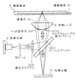
図4は、本発明の第1の実施形態の光ヘッド装置を示す。この光ヘッド装置の特徴は、対物レンズ4とホログラムレンズ107から2焦点レンズを構成することと、外周部の光量を低下させる補正ホログラム1221を設けることである。この光ヘッド装置において、半導体レーザなどの放射光源2から出射した光ビーム3は、コリメートレンズ122によって略平行光になり、補正ホログラム1221を通過して外周部の光強度が低下する。光ビームは、さらに、偏光ビームスプリッタ42を透過し、1/4波長板15によって円偏光になる。次に、光ビームは、ホログラムレンズ107と対物レンズ4とに入射し、異なった焦点位置に位置される厚い情報媒体5または薄い情報媒体51の上に集光される。情報媒体5は、基板の厚みt1=1.2mmの光ディスクであり、情報媒体51は、基板の厚みt2=0.6mmの光ディスクである。ここで、「基板の厚み」とは、情報媒体に光ビームの入射する面から情報記録面までの厚みを指す。また、ここで「集光」という言葉を用いたが、「集光」とは、「発散光または平行光を回折限界の微小スポットにまで収束すること」と定義する。
Hereinafter, a correction hologram or a correction filter and an optical system for condensing a light beam at two different positions will be described first with reference to the accompanying drawings.
FIG. 4 shows an optical head device according to the first embodiment of the present invention. This optical head device is characterized by forming a bifocal lens from the
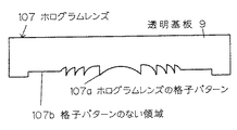
ホログラムレンズ107は、図5と図6に図式的に示すように、光ビーム3に対して透明な基板9に形成されていて、中央部の輪帯状の格子パターン107aと、その周囲の格子パターンのない領域107bとからなる。格子パターン107aは、同心円状であり、その中心すなわち光軸は対物レンズ4と組立誤差内で一致している。
As schematically shown in FIGS. 5 and 6, the
ホログラムレンズ107の+1次回折光の回折効率は100%未満であり、ホログラムレンズ107は、光ビーム3aの透過光(0次回折光)61aも、充分な強度を有するように設計する。これは、ホログラムレンズ107を例えば図4に示したように凹凸形状によって作製する場合には、(レリーフ型)凹凸の高さhをh<λ/(n−1)というようにより小さく、すなわち、格子部107aで光ビームに与える位相変化の振幅量を、2πよりも小さくすることによって、容易に実現できる。ここで、λは光ビーム3の波長、nは透明基板9の屈折率である。このようにホログラムレンズ107のどの位置においても、透過光が充分な強度を持つようにすることによって、情報媒体51上に透過光の形成する集光ビームのサイドローブ(図7参照)を低く抑えることができる効果を有する。
The diffraction efficiency of the + 1st order diffracted light of the
なお、ホログラムレンズ107が格子パターン107aと、格子パターンのない領域107bからなる。格子パターン107aの0次回折光(透過光)の位相は、格子パターン107aによって与えられる位相変調量の平均値となる。これに対し、格子パターンのない領域107bの透過光の位相を同じぐらいに合わせることによって、集光性能を向上させることが望ましい。そこで、例えばホログラムレンズ107の格子パターン107aをレリーフ型にする場合は、図6に示すように、格子パターン部の凹凸の平均ぐらいのレベルに格子パターンのない領域107bの表面の高さを合わせる。
The
情報媒体5または51で反射した光ビ−ムは、もとの光路を逆にたどる。透過光61は、実線で示したようにホログラムレンズ107を再び透過し、また、+1次回折光64は、破線のようにホログラムレンズ107で再び+1次回折光として回折し、どちらも初めに偏光ビームスプリッタ42を通った後と同じ光路を通り、偏光ビームスプリッタ42で反射される。反射された光は、収束レンズ121によって集光され、シリンドリカルレンズ131などの波面変換手段によってフォーカスエラー信号やトラッキングエラー信号などのサーボ信号を得ることができるように波面を変換された後に、光検出器71に入射する。光検出器71の出力を演算することによって、サーボ信号(フォーカスエラー信号とトラッキングエラー信号)及び情報信号を得ることができる。
The light beam reflected by the information medium 5 or 51 follows the original optical path in reverse. The transmitted light 61 is again transmitted through the
ホログラムレンズ107は、例えば図4に示したようにブレーズ化することによって、後述のように2焦点の光ビームを形成する透過光と+1次回折光との光量和を大きくすることができ、光の利用効率を高くできるという効果がある。
The
対物レンズ4は、図8の(a)に示すように、ホログラムレンズ107を回折されずに透過した光ビーム61が入射したときに、開口数NAが0.6以上で、基板37の厚みt2の薄い光ディスク51上に、回折限界の集光スポット38aを形成できるよう設計されている。また、この場合ではホログラムレンズ107の格子パターン107aは、対物レンズ4によって決まる開口よりも小さな径の中にだけ形成されている。従って、ホログラムレンズ107の格子パターンが形成されていない部分107bでは回折が全く起こらず、高NAの集光スポット38aの光量が多くなる。
As shown in FIG. 8A, the
他方、図8の(b)は、低NAで基板37の厚い(厚さt1)情報媒体5上に、回折限界に集光スポット38bを集光できることを示す。ホログラムレンズ107で回折された+1次回折光64は、対物レンズ4によって情報媒体5上に集光される。ここで+1次回折光64は、厚さt1の基板37を通して回折限界まで絞れるように収差補正を施されている。このような収差補正作用を有するホログラムレンズ107の設計方法は、例えば集光スポット38bから発散する球面波が、厚さt1の基板37を透過した後、対物レンズ4を透過し、ホログラムレンズ107を形成している透明基板9を透過した光ビームと、図8の(b)の光ビーム3の位相の正負を反転した光ビームの干渉パターン(ホログラムレンズの格子パターン107a)を計算すればよい。そして、例えばコンピューター・ジェネレイティッド・ホログラム(CGH)の手法などによって、容易にホログラムレンズ107を作製できる。このように、入射光の一部を回折するホログラムレンズ107と対物レンズ4とを組み合わせることによって、異なる基板厚(t1とt2)の光ディスク上に、それぞれ回折限界にまで集光される集光スポットを形成する事のできる2焦点レンズを実現できる。
On the other hand, FIG. 8B shows that the focused spot 38b can be focused at the diffraction limit on the information medium 5 having a low NA and a thick substrate (thickness t1). The + 1st order diffracted light 64 diffracted by the
ここで、ホログラムレンズ107はレンズ作用を有するので、2つの焦点の光軸方向の位置は異なり、一方の焦点スポットで情報の記録再生をしているときには、他方の焦点を集光点とする光ビームは大きく広がっており、光強度が小さく記録再生には影響を与えない。例えば図8の(a)のように、情報媒体51に対して集光スポット38aが合焦点位置にあるときは、+1次回折光64は情報媒体51の情報記録面上では大きく広がっており、記録再生には影響を与えない。これは図8の(b)の場合もまた同様である。
Here, since the
この2つの焦点位置の差は、一方の焦点スポットで情報の記録再生をしているときに、他方の焦点を集光点とする光ビームが大きく広がって光強度が小さく記録再生に影響を与えないようにするためには、50μm以上でなるべく大きくすることが望ましい。また、コンパクトディスク(CD)やレーザディスク(LD)などの基板厚t1が1.2mm程度で、高密度光ディスクの基板厚t2は0.4mm〜0.8mmが適当と考えられることから、対物レンズのフォーカスサーボ動作を担うアクチュエータの可動範囲を考えて、2焦点位置の差はt1とt2との差0.8mm程度を大きく越えないことが望ましい。従って、図8の(a)のように、高NAで薄い基板に対応した集光スポット38aの焦点距離を短くする場合、2焦点位置の差は50μm以上1mm以下にする。 The difference between the two focal positions affects the recording / reproduction when the information beam is recorded / reproduced at one focal spot, the light beam having the other focal point as the condensing point is greatly expanded and the light intensity is small. In order to avoid such a situation, it is desirable to make it as large as possible with 50 μm or more. Further, since the substrate thickness t1 of a compact disc (CD), laser disc (LD), etc. is about 1.2 mm and the substrate thickness t2 of the high-density optical disc is considered to be appropriate from 0.4 mm to 0.8 mm, the objective lens In consideration of the movable range of the actuator responsible for the focus servo operation, it is desirable that the difference between the two focal positions does not greatly exceed the difference of about 0.8 mm between t1 and t2. Therefore, as shown in FIG. 8A, when the focal length of the focused spot 38a corresponding to the thin substrate with high NA is shortened, the difference between the two focal positions is set to 50 μm or more and 1 mm or less.
本実施形態において、対物レンズ4は、図4に示すように、ホログラムレンズ107を回折されずに透過した光ビーム61が入射したときに、基板の厚み(t2)の薄い光ディスク上に回折限界の集光スポットを形成できるよう設計されている。また、本実施形態のホログラムレンズ107の格子パターン107aは、対物レンズ4によって決まる開口よりも小さな径の中にだけ形成されている。従って、ホログラムレンズ107の格子パターン107bの形成されていない部分では回折が全く起こらない。このように、入射光の一部を回折するホログラムレンズ107と対物レンズ4とを組み合わせることによって、異なる基板厚(t1とt2)の光ディスク上に、それぞれ回折限界にまで集光される集光スポットを形成することのできる2焦点レンズを実現できる。
In the present embodiment, as shown in FIG. 4, the
情報媒体5、51により反射されたホログラムレンズ107をふたたび通った上記の透過光61と上記の+1次回折光とは、偏光ビームスプリッタ42を初めに通ったときと同じ光路を通って偏光ビームスプリッタ42で反射され、次に、収束レンズ121によって集光される。この集光された光ビームを用いて光検出器71によりサーボ信号の検出を行う。従って、2焦点から反射してきた光ビームの光検出器側での集光点39は、放射光源2の出射点と共役関係にある点で一致する。このため、サーボ信号検出手段も光検出器71も単一のものを共通に用いることができ、少ない部品点数で小型、軽量、低コストの光ヘッド装置でありながら、異なる基板の厚みの光ディスクの記録再生を一つの光ヘッド装置で行うことができるという効果を有する。
The transmitted light 61 and the + 1st order diffracted light passing through the
フォーカスエラー信号の検出方式は、スポットサイズディテクション法(SSD法:特開平2−185722号公報)や、非点収差法や、ナイフエッジ法など任意の方法を用いることができる。また、トラッキングエラー信号は、プッシュプル法、ヘテロダイン法、3ビーム法など、やはり任意の方法を採用可能である。 As a detection method of the focus error signal, an arbitrary method such as a spot size detection method (SSD method: JP-A-2-185722), an astigmatism method, or a knife edge method can be used. As the tracking error signal, any method such as a push-pull method, a heterodyne method, and a three-beam method can be used.
本発明の特徴の1つは、補正ホログラム1221や補正フィルタ1225のような光強度を外周部で部分的に補正する素子を用いる点にある。光は強さと位相をもっているが、これらの素子は、光量と位相の変調素子であり、これを光学系に具備して光量と位相を所望どおりに変化させ、外周部での光強度を低下させる。
One of the features of the present invention is that an element such as a
図9に、放射光源2から対物レンズ4へと至る往路の光学系を示す。補正ホログラム1221は、例えば(b)に示すように、光軸3000に近いところには、光を全透過する透過部1223を設け、光軸3000から離れたところには、回折格子部1222を設ける。そして、(a)に示したように、往路において、放射光源2から出射した光ビーム3の光軸付近の光を全て透過し、光軸から離れた部分の光は一部を回折して透過率を低くする。
FIG. 9 shows an optical path in the forward path from the
ここで、回折格子部1222の0次回折光(透過光)の位相は、回折格子部1221によって与えられる位相変調量の平均値となる。これに対して、格子パターンのない領域1223の透過光の位相を同じぐらいに合わせることによって、対物レンズ4による集光性能を向上させることが望ましい。そこで、例えば図9の(b)に示すように、ホログラムの格子パターンをレリーフ型にする場合は、回折格子部1222の凹凸の平均(頂上部と底部の平均)ぐらいのレベルに透過部1223の表面の高さを合わせる。
Here, the phase of the 0th-order diffracted light (transmitted light) of the
ただし、放射光源2に半導体レーザーを用い、かつ、その半導体レーザーが非点隔差を持つ場合(図1参照)は、図10に示すように、光軸3000を含む中央部の透過部1223aの表面の高さを回析格子部1222の平均より高くする。いいかえれば、透過部1223aの厚みを回析格子部1222よりも厚くし、光路長を長くする。これによって、半導体レーザーの非点隔差の悪影響を減らし、光学系の集光特性をより良くすることもできる。半導体レーザーが非点隔差を持った場合、出射光の広がり角の狭い方向の平面内での集光点が、半導体レーザーの活性層内部へ入り込んでいる。従って、これと直角方向、つまり、出射光の広がり角の広い方向に光学系の凸レンズ作用をより大きくすることによって両方向の集光位置を一致させると、波面収差を低減できる。後述のように、図10のY方向を広がり角の広い方向に一致させることが望ましいので、このY方向に凸レンズ作用を持たせることが望ましい。これが、透過部1223aを厚くするとよい理由である。
However, when a semiconductor laser is used for the
また、補正ホログラム1221から回折する回折光1224は、不要な迷光になる。そこで、対物レンズ4の開口内に入らないようにするか、あるいは、情報媒体5または51で反射した後に、光検出器71に入射しないように設計することが望ましい。
Further, the diffracted light 1224 diffracted from the
回折光1224を対物レンズ4の開口内に入らないようにするには、回折格子部1222の格子ピッチを5μm以下、望ましくは2μm以下にするか、図9の(b)に示したように、光軸から離れる方向に回折する回折光強度が強くなる方向に回折格子部1222をブレーズ化した上で、格子ピッチを20μm以下、望ましくは12μm以下にする。
In order to prevent the diffracted light 1224 from entering the aperture of the
他の方法として、回折光1224が情報媒体5または51で反射した後に、光検出器71に入射しないように設計するためには、回折格子部の格子ピッチを30μm以下、望ましくは10μm以下にする。
As another method, in order to design so that the diffracted light 1224 does not enter the
また逆に、この回析光を情報媒体上に集光し、情報媒体からの反射光を光検出器で受光してその出力から、いわゆる3ビーム法によるトラッキングエラー信号を得ることも可能である。この場合は、上述の場合とは逆に光軸に近づく方向に回析する回析光強度が強くなる方向に回析格子部1222をブレーズ化することが望ましい。
Conversely, it is also possible to collect this diffracted light on an information medium, receive reflected light from the information medium with a photodetector, and obtain a tracking error signal by the so-called three-beam method from its output. . In this case, it is desirable to blaze the diffraction
図11は、補正ホログラム1221を図9の光軸3000の方向、すなわちZ方向から見た例を示す。光軸3000を表す丸と、光ビーム有効径1224を表す円は、説明のために仮想的に描いたもので、補正ホログラム1221には実際には形成しない。座標軸は、図1や図9と共通である。光ビームの広がり角度の広い方向、すなわち図1のY方向に光軸から離れた部分の光量を下げるため、図11においても、Y方向に光軸から離れた部分を回折格子部1222にすることが望ましい。
FIG. 11 shows an example in which the
また、遠視野像(FFP)の光強度の等高線は楕円形状であるので、回折格子部1222と透過部1223との境界線を光軸3000から外側に向かって凸にすることにより、光量を有効に利用できるという効果を得ることができる。
Further, since the contour line of the light intensity of the far field image (FFP) is elliptical, the amount of light is effectively increased by making the boundary line between the
図12は、補正ホログラム1221の0次回折効率(透過率)のY軸方向の変化の例を示す。原点は、光軸3000と補正ホログラム1221との交点である。外周ほど0次回折効率を低くする。このように、補正ホログラム1221を具備することにより、ホログラムレンズ107を通過した光ビームの遠視野像は、図13のようになる。
FIG. 12 shows an example of a change in the Y-axis direction of the zero-order diffraction efficiency (transmittance) of the
図13は、X方向(a)とY方向(b)の光強度の分布を示す。補正ホログラム1221によってY方向の光強度を低減することによって、Y方向の光強度分布(b)が、図2と異なっている。すなわち、Y方向の外周部の光強度が内周部よりも低くなっている。
FIG. 13 shows the light intensity distribution in the X direction (a) and the Y direction (b). By reducing the light intensity in the Y direction with the
なお、Y方向の外周部の光強度を内周部よりも低くするためには、補正ホログラム1221の回折格子部1222の0次回折効率を、ホログラムレンズ107の0次回折効率より低くすることが望ましい。
In order to make the light intensity at the outer peripheral portion in the Y direction lower than that at the inner peripheral portion, the 0th-order diffraction efficiency of the
図13の(b)の破線は、遠視野像を計算する際に用いた補正ホログラム1221の0次回折効率分布であり、図12の例とは少し異なっている。
The broken line in FIG. 13B is the 0th-order diffraction efficiency distribution of the
この時の情報媒体51上での集光スポットプロファイルを計算した結果を図14に示す。(a)X方向、(b)Y方向共にサイドローブ381の高さはメインローブ380の最大値の1%程度に納まっている。すなわち、情報媒体上で光ビーム(集光スポット)のサイドローブ381がより一層低くなり、優良な特性の再生信号を得ることができるという効果を得ることができる。
FIG. 14 shows the result of calculating the condensing spot profile on the information medium 51 at this time. The height of the
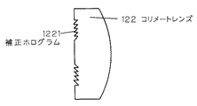
なお、図4のようにコリメートレンズ122を具備する構成では、図15に示したように、補正ホログラム1221をコリメートレンズ122の表面の周辺部に形成することによって部品点数を削減し、より安価に光ヘッド装置を構成することができる。
In the configuration including the
なお、以上の実施形態では、補正ホログラムはレリーフ型として説明してきたが、特開昭第61−189504号公報や、特開昭第63−241735号公報にも開示されているように、ニオブ酸リチウム基板の一部をプロトン交換したり、液晶セルを利用しても、同様に位相変調型の補正ホログラムを作製することができる。 In the above embodiment, the correction hologram has been described as a relief type. However, as disclosed in Japanese Patent Application Laid-Open Nos. 61-189504 and 63-241735, niobic acid is used. A phase-modulated correction hologram can be similarly produced by exchanging a part of the lithium substrate or using a liquid crystal cell.
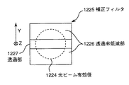
また、補正ホログラム1221において、回折格子部1222は透過率を低減するために設けているので、回折格子部の代わりに金属膜や誘電体膜を形成して透過率を低減しても良い。この場合、たとえば図16に示すように、補正ホログラムを設ける代わりに、図17に示す補正フィルタ1225が、偏光ビームスプリッタ42の表面に備えられる。この補正フィルタ1225は、金属膜または誘電体膜を両側に透過率低減部1226として設け、その間の中央に透過部1227を設けたものである。図16と図17に挿入したX軸とZ軸は共通である。光ビームの有効径1224は、透過部1227の幅より広くする。このようにビームスプリッタ42の表面に補正フィルタ1225を直接形成することにより、部品点数を低減できると共に、光学部品の面の数を低減でき、反射による光量の損失を避けることができるという効果を得ることができる。また、金属膜としては、安定なクロム等で形成することが望ましい。
Further, in the
なお、ビームスプリッタの表面に代えて、コリメートレンズ122において、表面に透過率低減部を設けても同様の効果を得ることができる。なお、反射光が半導体レーザーへの戻り光となって戻りノイズを誘発しないために、上記補正フィルタ表面の法線を光軸に対して傾けるとよい。特に図16のように補正フィルタ1225をビームスプリッタ42の表面に備える場合はビームスプリッタ42を傾ける。さらに、前述の回折格子を用いた実施形態と同様に、補正フィルタ1225の透過部1227を図18に示すように厚くし、光路長を長くすることによって、半導体レーザーの非点隔差の悪影響を取り除くことができるという効果をも得ることができる。
It should be noted that the same effect can be obtained by providing a transmittance reducing portion on the surface of the
本実施形態に用いる補正ホログラムまたは補正フィルタと一見似たものが特開昭第58−85944号公報及び特開昭第62−67737号公報に開示されている。前者には、光軸の傾きによるクロストークを減少させるため、たとえば透明な中央部と、光を吸収または反射する縁部とからなる放射減衰素子が光路中に設置され、縁部での放射強度を低減させる。また、後者では、主ビームの他に2本の副ビームを形成するため、光分割手段を光路中に設置する。ここで、サイドローブによるクロストークを減少するため、光分割手段は、主ビームの光強度分布を周辺部で小さくする。しかし、これらは、いずれも、通常の光ビームについて、周辺で光強度を低減させ、光ビームのサイドローブを小さくさせるものである。これに対し、本発明は、入射光の1部を回折するホログラムレンズ107を用いた2焦点レンズ特有の問題点を解決するものである。この場合、光量分布が図2の(b)に示したように特にy方向の外周部で大きく、情報読み取りが不安定になる可能性がある。そこで、本発明は、補正ホログラム(あるいは補正フィルタ)を用いて通常の平坦な光強度分布に戻すものである。これにより、本発明は、上述の従来技術よりもサイドローブ低減の効果が大きく、かつ、異なる基材厚に適した光ビームを1つのレンズで形成できるという顕著な効果を得ることができるものである。
Japanese Patent Application Laid-Open No. 58-85944 and Japanese Patent Application Laid-Open No. 62-67737 disclose apparently similar correction holograms or correction filters used in this embodiment. In the former, in order to reduce crosstalk due to the tilt of the optical axis, for example, a radiation attenuation element consisting of a transparent central part and an edge part that absorbs or reflects light is installed in the optical path, and the radiation intensity at the edge part Reduce. In the latter case, in order to form two sub beams in addition to the main beam, the light dividing means is installed in the optical path. Here, in order to reduce crosstalk due to side lobes, the light splitting means reduces the light intensity distribution of the main beam at the peripheral portion. However, both of these reduce the light intensity around the normal light beam and reduce the side lobe of the light beam. On the other hand, the present invention solves a problem peculiar to a bifocal lens using a
図19に示すように、本光ヘッド装置では、情報記録面上に集光されて情報を読みとった光の一部は光検出器上で大きく広がる。例えば、ホログラムレンズ107を用いた本発明の光ヘッド装置で、情報媒体51(基板の厚みがt2の時)の再生を行うとき、情報記録面上に集光されて情報を読みとった光が、ホログラムレンズ107を透過した光を用いてサーボ信号や情報信号を読み出す。ここで、情報記録面上に集光されて情報を読みとった光がホログラムレンズ107で回折された光は、図19に示した1次回折光430の様に大きく広がる。そこで、サーボ信号検出用の光検出器75の周囲に大きな(望ましくはφ1mm以上の大きさの)光検出器75cを設けて、これらの光を受光し、光検出器75の出力と、光検出器75cの出力の和を情報信号とする。これにより、さらに、S/Nを向上し、また、周波数特性の向上を図ることもできるという効果を得ることができる。
As shown in FIG. 19, in the present optical head device, a part of the light that has been collected on the information recording surface and read the information largely spreads on the photodetector. For example, in the optical head device of the present invention using the
次に、添付の図面を用いて本発明の実施の形態のうち、ホログラムレンズと屈折型レンズとを一体成形する実施形態を説明する。
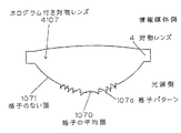
本実施形態で用いる対物レンズは、光を屈折する対物レンズ4と光の一部を回折するホログラムレンズ107との組み合わせで基本的に構成されている。そこで、ホログラムレンズ107と対物レンズ4とを、図20に示すように、対物レンズ4上にホログラムレンズの格子パターンを直接作製することにより一体化してもよい。こうすることによって、ホログラムレンズと対物レンズとの光軸ずれを小さくすることができ、ホログラムレンズの+1次回折光の軸外収差をより小さくでき、かつ、一層の軽量化と低コスト化を図ることもできるという効果がある。
Next, among the embodiments of the present invention, an embodiment in which a hologram lens and a refractive lens are integrally formed will be described with reference to the accompanying drawings.
The objective lens used in the present embodiment is basically composed of a combination of the
さらにまた、設計上ホログラムレンズが光軸に対して傾くと収差が発生するような場合は、図20に示すように、ホログラムレンズ107の格子パターンを対物レンズ4の曲率の大きな(曲率半径の小さな)面、すなわち情報媒体(光ディスク)の逆側に形成することにより、ホログラムレンズの光軸に対する収差を抑圧することができるという効果を得ることもまた可能である。
Furthermore, in the case where an aberration occurs when the hologram lens is tilted with respect to the optical axis by design, as shown in FIG. 20, the grating pattern of the
なお、図20の格子パターン107aの0次回折光(透過光)の位相は、格子パターン107aによって与えられる位相変調量の平均値となる。従って、格子パターン107aの格子の凹凸の高さの平均の面1070(点線で表示)と、格子パターンのない面1071との表面を連続的につなぎ、かつ、格子パターン107aの格子の平均面1070と格子パターンのない面1071との表面を、基板厚t2を通して光ビームをほぼ回折限界に集光できるように設計する。
Note that the phase of the 0th-order diffracted light (transmitted light) of the grating pattern 107a in FIG. 20 is an average value of the phase modulation amount given by the grating pattern 107a. Therefore, the average surface 1070 (indicated by dotted lines) of the height of the unevenness of the lattice of the lattice pattern 107a and the
さらに、次の実施形態として、ホログラムレンズ107を凸レンズ型に設計し、+1次回折光を、基板厚みt2に対して集光し、0次光を基板厚みt1に対して集光することも可能である。この時、外周部の+1次回折効率はほぼ100%とし、内周部の回折効率は100%より小さくする。そして、上述の実施形態の説明中、ホログラムレンズ107の0次回折効率を+1次回折効率と読み代え、ホログラムレンズ107の+1次回折効率を0次回折効率と読み代えることにより、補正ホログラム1221は、同様の構成で同様の効果を得ることができる。そして、この実施形態では基板厚t2に対して、色収差が低減される、あるいは、発生しなくなるという効果がある。また逆に、この回析光を情報媒体上に集光し、情報媒体からの反射光を光検出器で受光して、その出力から、いわゆる3ビーム法によるトラッキングエラー信号を得ることも可能である。この場合は、上述とは逆に、光軸に近づく方向に回析する回析光強度が強くなる方向に回析格子部1222をブレーズ化することが望ましい。
Furthermore, as a next embodiment, the
なお、図21は、光ヘッド装置の別の実施形態の概略を示す。この光ヘッド装置が図4に示す光ヘッド装置と異なる点は、有限光学系を用いている点と、ビームスプリッタ363が平板である点である。この差異により、部品点数の低減とコストダウンの効果がある。放射光源2からの光ビーム3は、補正ホログラム1221により外周部の光強度を変化された後、ビームスプリッタ363により90°反射されて、ホログラムレンズの格子パターン107を備えた対物レンズ(2焦点レンズ)4(図20参照)により、情報媒体5、51上に集光される。情報媒体5、51からの反射光は、ビームスプリッタ363を透過して、光検出器71に入射する。
FIG. 21 shows an outline of another embodiment of the optical head device. The optical head device differs from the optical head device shown in FIG. 4 in that a finite optical system is used and the
光量と位相の変調素子(補正フィルタなど)は、簡単に製造できることが望ましい。補正フィルタ1225は、透過率低減部1226と段差の2種のパターンを形成する必要があるが、以下に例示する製作法においては、パターニングのためのマスキング工程は1回だけ行えばよく、簡単かつ安価に製造可能である。以下、透過率低減部1226は、クロムなどの金属膜を例にとって説明するが、誘電体膜に代えることもできる。図22は、補正フィルタ1225の製造法を示す。
It is desirable that a light quantity and phase modulation element (such as a correction filter) can be easily manufactured. The
まず、(a)に示すように、透明基板12252を洗浄したのち、レジスト膜12251をその表面にコートする。基板12252は、図16に示した例のように、ビームスプリッタ42の表面に補正フィルタ1225を作成する場合は、ビームスプリッタそのものである。
First, as shown in (a), after the
次に、(b)に示すように、基板12254上の1部に光を遮るマスク材料(一般的にクロム)12255を形成したフォトマスク12253がレジスト膜12251の上に載せられる。このフォトマスク12253を通してレジスト膜12251をパターニングのために露光する。
Next, as shown in (b), a
次に、(c)に示すように、フォトマスク12253を除いて、レジスト膜12251を現像する。これにより、補正フィルタ1225の透過部1227に相当する部分のみにレジスト膜が残る。
Next, as shown in (c), the resist
次に、(d)に示すように、残ったレジスト膜12251をマスクにしてエッチングを行なう。これにより、基板12252の表面のうち、レジスト膜12251のない部分のみがエッチングされる。こうして、レジスト膜12251を上に載せた段差が形成される。
Next, as shown in (d), etching is performed using the remaining resist
次に、(e)に示すように、金属膜12261を蒸着またはスパッタにより形成する。金属膜12261の厚さは、段差の高さより小さい。
Next, as shown in (e), a
最後に、(f)に示すように、レジスト膜12251を有機溶剤などにより除去する。このとき、レジスト膜12251上に形成された金属膜も同時に除去できる(リフトオフ)。こうして、補正フィルタ1225が完成する。
Finally, as shown in (f), the resist
図23は、補正フィルタ1225の別の製造法を示す。まず、(a)に示すように、透明基板12252を洗浄したのち、基板12251の表面上に金属膜12261を蒸着する。
FIG. 23 shows another method for manufacturing the
次に、(b)に示すように、さらにレジスト膜12251を金属膜12261上に塗布する。
Next, as shown in (b), a resist
次に、(c)に示すように、基板12254上の1部に光を遮るマスク材料(一般的にクロム)12255を形成したフォトマスク12253がレジスト膜12251の上に載せられる。マスク材料12255は、中央部以外に形成される。このフォトマスク12253を通してレジスト膜12251をパターニングのために露光する。
Next, as shown in (c), a
次に、フォトマスク12253を取り除き、レジスト膜12251を現像する。こうして、(d)に示すように、レジスト膜12251は、露光されない部分にのみ残る。
次に、残ったレジスト膜12251をマスクにして金属膜12261をエッチする。こうして、(e)に示すように、透過部1227に相当する部分の金属膜12261が除去される。
Next, the
Next, the
次に、(f)に示すように、SiO2などの透明な膜12262を形成する。この膜12262の厚さは、金属膜12261の厚さより大きい。
Next, as shown in (f), a
次に、(g)に示すように、レジスト膜12251を溶剤で溶かすなどして除去する。このとき、レジスト膜12251の上に載っているSiO2は、同時に除去される(リフトオフ)。こうして、補正フィルタ1225が完成する。
Next, as shown in (g), the resist
本発明に係る対物レンズの設計方法、光ヘッド装置及び光ディスク装置は、光媒体もしくは光磁気媒体(情報媒体)上に記憶される情報の記録・再生あるいは消去に利用される。 The objective lens designing method, the optical head device, and the optical disk device according to the present invention are used for recording / reproducing or erasing information stored on an optical medium or a magneto-optical medium (information medium).
2 放射光源、 3 光ビーム、 4 対物レンズ、 5、51 情報媒体、 71 光検出器、 36 ビームスプリッタ、 107 ホログラムレンズ、 121 収束レンズ、 122 コリメートレンズ、 1221 補正ホログラム、 1225 補正フィルタ。 2 radiation source, 3 light beam, 4 objective lens, 5, 51 information medium, 71 photodetector, 36 beam splitter, 107 hologram lens, 121 converging lens, 122 collimating lens, 1221 correction hologram, 1225 correction filter.
Claims (4)
光源と、
前記光源から出射される光を受けて、前記第1の情報媒体又は前記第2の情報媒体の情報記録面上に光を集光させる対物レンズと、
前記第1の情報媒体又は前記第2の情報媒体で反射した光を受けて、電気信号に変換する光検出器と、を具備し、
前記対物レンズは、基板を有する情報媒体の情報記録面上に、前記基板を介して光を集光させる対物レンズであって、屈折型レンズと、収差補正作用を持つホログラムレンズとを具備し、
前記ホログラムレンズは、複数の領域を具備し、
前記複数の領域は、第1領域と、前記第1領域に比して前記対物レンズの光軸に近い第2領域とを含み、
前記ホログラムレンズは前記屈折型レンズの曲率の大きい方の面すなわち曲率半径の小さい方の面に一体形成しており、
前記第1領域を通過した光と、前記第2領域を通過した光の両方を、第1の厚さの基板を有する第1の情報媒体の情報記録面上に、前記第1の厚さの基板を介して集光させ、
前記第2領域を通過した光のみを、第2の厚さの基板を有する第2の情報媒体の情報記録面上に、前記第2の厚さの基板を介して集光させ、
前記第1の厚さは、前記第2の厚さに比して薄く、
前記第1の厚さの基板を介して光が集光するための開口数は、前記第2の厚さの基板を介して光が集光するための開口数に比して大きく、
前記光源は、非点隔差をもつ半導体レーザーであって、
前記光源から前記対物レンズへと至る光路中に、光強度補正素子を具備し、
前記光強度補正素子は液晶セルによって構成され、前記液晶セルが収差を低減することを特徴とする光ヘッド装置。 An optical head device that records or reproduces information on a first information medium having a substrate having a first thickness and a second information medium having a substrate having a second thickness,
A light source;
An objective lens for receiving light emitted from the light source and condensing the light on the information recording surface of the first information medium or the second information medium;
A photodetector that receives the light reflected by the first information medium or the second information medium and converts it into an electrical signal;
The objective lens is on the information recording surface of the information medium having a substrate, a objective lens for collecting the light through the substrate, comprising a refraction lens, and a hologram lens having an aberration correction action ,
The hologram lens comprises a plurality of regions,
The plurality of regions include a first region and a second region closer to the optical axis of the objective lens than the first region,
The hologram lens is integrally formed on a surface having a larger curvature of the refractive lens, that is, a surface having a smaller radius of curvature,
Both the light that has passed through the first area and the light that has passed through the second area have the first thickness on the information recording surface of the first information medium having the substrate having the first thickness. Condensing through the substrate,
Only the light that has passed through the second region is condensed on the information recording surface of the second information medium having the second thickness substrate through the second thickness substrate,
The first thickness is smaller than the second thickness,
The numerical aperture for the first light through the substrate thickness is collecting light, the light through the second thickness substrate rather large compared to the numerical aperture for focusing the light,
The light source is a semiconductor laser having an astigmatic difference,
In the optical path from the light source to the objective lens, a light intensity correction element is provided,
2. The optical head device according to claim 1, wherein the light intensity correction element includes a liquid crystal cell, and the liquid crystal cell reduces aberration .
前記第1の厚さの基板を有する前記第1の情報媒体の情報記録面上に、前記第1の厚さの基板を介して集光させた場合と、
前記第2の厚さの基板を有する前記第2の情報媒体の情報記録面上に、前記第2の厚さの基板を介して集光させた場合と、
いずれの場合も共通の光検出器によって光を受けて電気信号に変換することを特徴とする請求項1または2に記載の光ヘッド装置。 The light emitted from the light source,
When the light is condensed on the information recording surface of the first information medium having the substrate having the first thickness through the substrate having the first thickness;
When the light is condensed on the information recording surface of the second information medium having the second thickness substrate through the second thickness substrate;
3. The optical head device according to claim 1, wherein light is received by a common photodetector and converted into an electric signal in any case.
前記光源から出射した光を、前記第1の情報媒体又は前記第2の情報媒体の情報記録面上に集光し、
前記第1の情報媒体又は前記第2の情報媒体から反射して戻る光を前記光検出器で受光することによってトラッキングエラー信号を検出し、
前記第1の情報媒体又は前記第2の情報媒体の情報再生を行うことを特徴とする光ディスク装置。 And the first information medium having a first thickness substrate, claims 1 to 3 for recording or reproducing information for the second of the second information medium having a thick substrate Using any one of the optical head devices,
Condensing the light emitted from the light source on the information recording surface of the first information medium or the second information medium;
A tracking error signal is detected by receiving light reflected from the first information medium or the second information medium by the photodetector;
An optical disc apparatus for reproducing information from the first information medium or the second information medium.
Priority Applications (1)
| Application Number | Priority Date | Filing Date | Title |
|---|---|---|---|
| JP2004164262A JP4201196B2 (en) | 1995-05-30 | 2004-06-02 | Optical head device and optical disk device |
Applications Claiming Priority (2)
| Application Number | Priority Date | Filing Date | Title |
|---|---|---|---|
| JP13136095 | 1995-05-30 | ||
| JP2004164262A JP4201196B2 (en) | 1995-05-30 | 2004-06-02 | Optical head device and optical disk device |
Related Parent Applications (1)
| Application Number | Title | Priority Date | Filing Date |
|---|---|---|---|
| JP2003293771A Division JP2004039248A (en) | 1995-05-30 | 2003-08-15 | Objective lens, optical head unit, and optical disk device |
Publications (3)
| Publication Number | Publication Date |
|---|---|
| JP2004281050A JP2004281050A (en) | 2004-10-07 |
| JP2004281050A5 JP2004281050A5 (en) | 2007-04-19 |
| JP4201196B2 true JP4201196B2 (en) | 2008-12-24 |
Family
ID=33301327
Family Applications (1)
| Application Number | Title | Priority Date | Filing Date |
|---|---|---|---|
| JP2004164262A Expired - Lifetime JP4201196B2 (en) | 1995-05-30 | 2004-06-02 | Optical head device and optical disk device |
Country Status (1)
| Country | Link |
|---|---|
| JP (1) | JP4201196B2 (en) |
Families Citing this family (1)
| Publication number | Priority date | Publication date | Assignee | Title |
|---|---|---|---|---|
| US7935958B2 (en) * | 2004-10-22 | 2011-05-03 | Semiconductor Energy Laboratory Co., Ltd. | Semiconductor device |
-
2004
- 2004-06-02 JP JP2004164262A patent/JP4201196B2/en not_active Expired - Lifetime
Also Published As
| Publication number | Publication date |
|---|---|
| JP2004281050A (en) | 2004-10-07 |
Similar Documents
| Publication | Publication Date | Title |
|---|---|---|
| KR100283502B1 (en) | Optical head apparatus | |
| JP3677319B2 (en) | Focus control method and optical disc apparatus | |
| JPH1092002A (en) | Diffraction grating lens | |
| JPH1010308A (en) | Hologram, condensing optical system formed by using hologram as well as optical head device optical disk device having this condensing optical system | |
| US7206275B2 (en) | Optical pickup device | |
| JPH04318333A (en) | Optical head device | |
| JP3677342B2 (en) | Optical head device and optical disk device | |
| JP4201196B2 (en) | Optical head device and optical disk device | |
| JP3550914B2 (en) | Optical pickup device | |
| JP3661680B2 (en) | Optical lens, optical head device, and optical disk device | |
| JPH0950648A (en) | Optical head device | |
| JPH0460931A (en) | Optical pickup | |
| JP2004039248A (en) | Objective lens, optical head unit, and optical disk device | |
| JP3514708B2 (en) | Optical pickup device | |
| JP3823912B2 (en) | optical disk | |
| JP3982547B2 (en) | Optical lens, optical head device, information device | |
| JP3982546B2 (en) | Optical lens, optical head device, information device | |
| JP4155297B2 (en) | Optical disc and optical disc recording / reproducing method | |
| JP4148287B2 (en) | Optical lens and diffraction lens, optical head device, optical information device | |
| JP2006313647A (en) | Optical lens and optical head device, optical disk device | |
| JP4068651B2 (en) | Optical lens and optical head device and optical disk device using the same | |
| JP3462988B2 (en) | Diffraction grating and optical pickup for generating multiple beams | |
| JPH0453031A (en) | Optical head device | |
| JPH01220133A (en) | Optical head device | |
| JP2006079822A (en) | Optical head device and liquid crystal cell, and optical disk device |
Legal Events
| Date | Code | Title | Description |
|---|---|---|---|
| A521 | Written amendment |
Free format text: JAPANESE INTERMEDIATE CODE: A523 Effective date: 20070307 |
|
| A131 | Notification of reasons for refusal |
Free format text: JAPANESE INTERMEDIATE CODE: A131 Effective date: 20070612 |
|
| A521 | Written amendment |
Free format text: JAPANESE INTERMEDIATE CODE: A523 Effective date: 20070808 |
|
| A02 | Decision of refusal |
Free format text: JAPANESE INTERMEDIATE CODE: A02 Effective date: 20080318 |
|
| A521 | Written amendment |
Free format text: JAPANESE INTERMEDIATE CODE: A523 Effective date: 20080519 |
|
| A911 | Transfer of reconsideration by examiner before appeal (zenchi) |
Free format text: JAPANESE INTERMEDIATE CODE: A911 Effective date: 20080528 |
|
| TRDD | Decision of grant or rejection written | ||
| A01 | Written decision to grant a patent or to grant a registration (utility model) |
Free format text: JAPANESE INTERMEDIATE CODE: A01 Effective date: 20080902 |
|
| A01 | Written decision to grant a patent or to grant a registration (utility model) |
Free format text: JAPANESE INTERMEDIATE CODE: A01 |
|
| A61 | First payment of annual fees (during grant procedure) |
Free format text: JAPANESE INTERMEDIATE CODE: A61 Effective date: 20081002 |
|
| R150 | Certificate of patent or registration of utility model |
Free format text: JAPANESE INTERMEDIATE CODE: R150 |
|
| FPAY | Renewal fee payment (event date is renewal date of database) |
Free format text: PAYMENT UNTIL: 20111017 Year of fee payment: 3 |
|
| FPAY | Renewal fee payment (event date is renewal date of database) |
Free format text: PAYMENT UNTIL: 20121017 Year of fee payment: 4 |
|
| FPAY | Renewal fee payment (event date is renewal date of database) |
Free format text: PAYMENT UNTIL: 20131017 Year of fee payment: 5 |
|
| EXPY | Cancellation because of completion of term |


