JP4201033B2 - Inkjet recording device - Google Patents
Inkjet recording device Download PDFInfo
- Publication number
- JP4201033B2 JP4201033B2 JP2006208692A JP2006208692A JP4201033B2 JP 4201033 B2 JP4201033 B2 JP 4201033B2 JP 2006208692 A JP2006208692 A JP 2006208692A JP 2006208692 A JP2006208692 A JP 2006208692A JP 4201033 B2 JP4201033 B2 JP 4201033B2
- Authority
- JP
- Japan
- Prior art keywords
- recording
- paper
- recording medium
- belt
- stocker
- Prior art date
- Legal status (The legal status is an assumption and is not a legal conclusion. Google has not performed a legal analysis and makes no representation as to the accuracy of the status listed.)
- Expired - Fee Related
Links
Images

Classifications
-
- B—PERFORMING OPERATIONS; TRANSPORTING
- B41—PRINTING; LINING MACHINES; TYPEWRITERS; STAMPS
- B41J—TYPEWRITERS; SELECTIVE PRINTING MECHANISMS, i.e. MECHANISMS PRINTING OTHERWISE THAN FROM A FORME; CORRECTION OF TYPOGRAPHICAL ERRORS
- B41J29/00—Details of, or accessories for, typewriters or selective printing mechanisms not otherwise provided for
- B41J29/17—Cleaning arrangements
-
- B—PERFORMING OPERATIONS; TRANSPORTING
- B41—PRINTING; LINING MACHINES; TYPEWRITERS; STAMPS
- B41J—TYPEWRITERS; SELECTIVE PRINTING MECHANISMS, i.e. MECHANISMS PRINTING OTHERWISE THAN FROM A FORME; CORRECTION OF TYPOGRAPHICAL ERRORS
- B41J11/00—Devices or arrangements of selective printing mechanisms, e.g. ink-jet printers or thermal printers, for supporting or handling copy material in sheet or web form
- B41J11/0015—Devices or arrangements of selective printing mechanisms, e.g. ink-jet printers or thermal printers, for supporting or handling copy material in sheet or web form for treating before, during or after printing or for uniform coating or laminating the copy material before or after printing
-
- B—PERFORMING OPERATIONS; TRANSPORTING
- B41—PRINTING; LINING MACHINES; TYPEWRITERS; STAMPS
- B41J—TYPEWRITERS; SELECTIVE PRINTING MECHANISMS, i.e. MECHANISMS PRINTING OTHERWISE THAN FROM A FORME; CORRECTION OF TYPOGRAPHICAL ERRORS
- B41J11/00—Devices or arrangements of selective printing mechanisms, e.g. ink-jet printers or thermal printers, for supporting or handling copy material in sheet or web form
- B41J11/007—Conveyor belts or like feeding devices
Description
本発明は、被記録媒体に画像を形成するインクジェット記録装置に関する。 The present invention relates to an ink jet recording apparatus that forms an image on a recording medium.
記録用紙等の被記録媒体にノズルからインク滴を吐出して画像を形成するインクジェットプリンタ(インクジェット記録装置)としては、用紙収容部から取り出された被記録媒体を、ノズルが開口しているインクジェットヘッドのインク吐出面と対向する位置に搬送する搬送ベルトを有するものが知られている(特許文献1)。 As an ink jet printer (ink jet recording apparatus) for forming an image by ejecting ink droplets from a nozzle onto a recording medium such as recording paper, an ink jet head in which the nozzle is opened on the recording medium taken out from the paper storage unit One having a transport belt for transporting to a position facing the ink ejection surface is known (Patent Document 1).
被記録媒体の表面には紙粉などの付着物が付着していることが多い。このため、用紙収容部から取り出された被記録媒体が、インクジェットヘッドのインク吐出面と対向する位置に搬送されるまでに、被記録媒体の表面から付着物が剥離して周囲に飛散する。飛散した付着物は、搬送ベルト周辺を浮遊してインクジェットヘッドのインク吐出面に付着し、ノズルの開口を塞いだり、ノズル内に侵入したりすることがある。これらは、インク滴の吐出不良の原因となる。そこで、インクジェットヘッドの近傍において、被記録媒体の表面に付着している付着物を除去する付着物除去装置を配置することが考えられる。しかしながら、付着物除去装置で除去しきれない付着物が飛散するため、飛散した付着物がインクジェットヘッドのインク吐出面に付着するのを確実に抑制することは難しい。 There are many cases where deposits such as paper dust adhere to the surface of the recording medium. For this reason, before the recording medium taken out from the paper storage unit is transported to a position facing the ink ejection surface of the inkjet head, the deposits are peeled off from the surface of the recording medium and scattered around. The scattered deposits may float around the conveyor belt and adhere to the ink discharge surface of the inkjet head, block the nozzle opening, or enter the nozzle. These cause ink droplet ejection failure. In view of this, it is conceivable to arrange a deposit removing device for removing deposits adhering to the surface of the recording medium in the vicinity of the inkjet head. However, since the deposits that cannot be removed by the deposit removal device are scattered, it is difficult to reliably prevent the scattered deposits from adhering to the ink discharge surface of the inkjet head.
そこで、本発明は、飛散した被記録媒体の付着物がインク吐出面に付着するのを確実に抑制することができるインクジェット記録装置を提供することを目的とする。 SUMMARY An advantage of some aspects of the invention is that it provides an ink jet recording apparatus that can reliably prevent scattered deposits on a recording medium from adhering to an ink discharge surface.
本発明のインクジェット記録装置は、複数の被記録媒体を収容するストッカと、前記ストッカの上方に配置され、複数のローラに架け渡されていると共に外周面が粘着性を有する無端の搬送ベルトを有しており、前記ストッカに収容された前記被記録媒体を、上方に反転させて、前記搬送ベルトの前記外周面における下方に向いた下方面に、当該被記録媒体の記録面が下方に向くように粘着させる搬送装置と、前記下方面に対向し、前記下方面に粘着された前記被記録媒体の前記記録面に付着した付着物を、当該記録面に当接することによって除去する付着物除去ローラと、前記搬送ベルトの前記外周面における上方に向いた上方面に位置する前記被記録媒体の前記記録面にインク滴を吐出するノズルを有するインクジェットヘッドとを備えている。 Ink jet recording apparatus of the present invention is used, the number and the stocker for accommodating a plurality of recording media, is disposed above the stocker, the outer peripheral surface with which spans a plurality of rollers conveying belts endless having adhesiveness and is, the recording medium accommodated in the stocker, is inverted upward, the lower surface facing downward in the outer circumferential surface of the conveyor belt, so that the recording surface of the recording medium faces downward a conveying device for viscous wear, opposed to the lower surface, the deposits adhered to the recording surface of the adhesive has been the recording medium to the bottom surface, deposit removing for removing by abutting on the recording surface It includes a roller, and an ink jet head having nozzles for ejecting ink droplets onto the recording surface of the recording medium located upper face facing upwardly in the outer peripheral surface of the conveyor belt There.
本発明によると、記録面が下方に向くように搬送ベルトの下方面に被記録媒体が粘着された状態で、当該記録面の付着物が付着物除去ローラによって除去される。このとき、除去される際に遊離したり飛散した付着物は搬送ベルトの下方に向かって落下する。このため、このように離脱した付着物が搬送ベルトの上方面の上方に位置するインクジェットヘッドのノズル面に付着するのを確実に抑制することができる。 According to the present invention, the deposit on the recording surface is removed by the deposit removing roller while the recording medium is adhered to the lower surface of the conveying belt so that the recording surface faces downward. At this time, the deposits that have been released or scattered when removed fall down toward the bottom of the conveyor belt. For this reason, it can suppress reliably that the deposit | attachment isolate | separated in this way adheres to the nozzle surface of the inkjet head located above the upper surface of a conveyance belt.
本発明においては、前記搬送ベルトの前記上方面及び前記インクジェットヘッドを覆うカバーをさらに備えていることが好ましい。これによると、離脱した付着物がインクジェットヘッドのノズル面に付着するのをより確実に抑制することができる。 In the present invention, it is preferable to further include a cover that covers the upper surface of the conveyor belt and the inkjet head. According to this, it can suppress more reliably that the detached deposit | attachment adheres to the nozzle surface of an inkjet head.
本発明においては、前記カバーに囲まれた内部空間の圧力を正圧に維持する圧力制御装置をさらに備えていることがより好ましい。これによると、カバーの内部空間から外部に向かう空気の流れが形成されるため、飛散した付着物がカバー内に侵入しにくくなり、付着物がインクジェットヘッドのノズル面に付着するのをより一層確実に抑制することができる。また、本発明においては、前記付着物除去ローラの前記被記録媒体の搬送方向に関する下流側において、前記ストッカと前記搬送ベルトとの間に配置されているダストトレイをさらに備えていることがより一層好ましい。 In the present invention, it is more preferable to further include a pressure control device that maintains the pressure in the internal space surrounded by the cover at a positive pressure. According to this, since the air flow from the inner space of the cover to the outside is formed, the scattered deposits are less likely to enter the cover, and the deposits are more reliably attached to the nozzle surface of the inkjet head. Can be suppressed. Further, in the present invention, it is further provided that a dust tray disposed between the stocker and the transport belt is further provided on the downstream side of the deposit removal roller in the transport direction of the recording medium. preferable.
以下、本発明の好適な実施の形態について、図面を参照しつつ説明する。 Hereinafter, preferred embodiments of the present invention will be described with reference to the drawings.
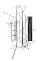
図1は、本発明に係る好適な実施形態であるインクジェットプリンタの全体的な構成を示す概略側面図である。図2は、本発明の要部の構成を示す図であって、図2(a)は、上方より見たときの平面図であり、図2(b)は、図2(a)中に示すX-X線で切断したときの断面図である。図1に示すように、インクジェットプリンタ(インクジェット記録装置)101は、4つのインクジェットヘッド1を有するカラーインクジェットプリンタである。また、インクジェットプリンタ101内には、被記録媒体である用紙Pの搬送経路(図中実線矢印参照)に沿って給紙装置(供給装置)11、付着物除去ローラ(付着物除去装置)20、搬送装置13及び排紙トレイ12が配置されている。
FIG. 1 is a schematic side view showing an overall configuration of an ink jet printer which is a preferred embodiment according to the present invention. FIG. 2 is a diagram showing a configuration of a main part of the present invention. FIG. 2 (a) is a plan view when viewed from above, and FIG. 2 (b) is shown in FIG. 2 (a). It is sectional drawing when cut | disconnecting by XX line shown. As shown in FIG. 1, an inkjet printer (inkjet recording apparatus) 101 is a color inkjet printer having four
給紙装置11は、用紙ストッカ11aと、ピックアップローラ11bと、ガイドプレート16bとを有している。用紙ストッカ11aは、その内部に積載された多数の用紙Pを収容するものである。ピックアップローラ11bは、図示しないモータで駆動されることによって、用紙ストッカ11a内に積載された用紙Pを上から一枚ずつピックアップすると共に、ピックアップした用紙Pを図中左方に送り出す。ガイドプレート16bは、ピックアップローラ11bによって送り出された用紙Pを、給紙装置11の上方に配置されている搬送装置13までガイドするものであり、図中左方に送り出された用紙Pを上方反転させつつ図中右方に向かって送り出す。送り出された用紙Pは、用紙Pの印刷面(記録面)が下方に向くように、搬送装置13の搬送ベルト8の外周面における下方面8a上に搬送される。
The
搬送装置13は、給紙装置11から送り出された用紙Pを搬送するものであり、2つのベルトローラ6、7の間に架け渡されるように巻き回されたエンドレスの搬送ベルト8と、搬送ベルト8によって囲まれた領域内において4つのインクジェットヘッド1と対向する位置に配置されたプラテン15とを有している。さらに、搬送装置13は、その搬送経路の最上流部にニップローラ16aを備えており、搬送ベルト8の下方面8a上において、搬送されてきた用紙Pをベルトローラ6との間で挟む。ニップローラ16aは、弾性部材で構成されており、用紙Pを搬送ベルト8に押圧しながら下流側に送り出す。搬送ベルト8の外周面は粘着性を有している。そのため、ニップローラ16aによって、用紙Pは、搬送ベルト8の下方面8a上に粘着される。
The
プラテン15は、インクジェットヘッド1と対向する領域において搬送ベルト8とインクジェットヘッド1との間のギャップを一定に保つように搬送ベルト8を支持するものである。これにより、搬送ベルト8の上下方向への撓みも防止される。
The
図示しない搬送モータがベルトローラ6を回転させると搬送ベルト8が駆動される。これにより、搬送ベルト8の下方面8aに載置された用紙Pが、図中右方に向かって搬送され、さらに、搬送ベルト8に沿って上方反転された後、搬送ベルト8の外周面における上方を向いている上方面8b上を図中左方に向かって搬送される。
When a conveyance motor (not shown) rotates the belt roller 6, the conveyance belt 8 is driven. As a result, the paper P placed on the
搬送ベルト8の上方面8bの下流側端部近傍には、剥離板14が設けられている。搬送ベルト8に搬送された用紙Pは、剥離板14により搬送ベルト8の外周面から剥離される。搬送ベルト8の外周面から剥離された用紙Pは、さらに下流側に配置された排紙トレイ12に排紙される。
A peeling plate 14 is provided in the vicinity of the downstream end of the
インクジェットヘッド1は、インク滴を吐出するノズル108を含むインク流路が内部に形成されており、図2(a)に示すように、搬送方向に直交した方向に長尺な細長い直方体形状を有している。図中の矢印は搬送方向を示している。そして、4つのインクジェットヘッド1は、4色のインク(マゼンタ、イエロー、シアン、ブラック)に対応して、用紙Pの搬送方向に沿って4つ並べて設けられている。いずれも、搬送方向と直交する方向に用紙Pを跨ぐように固定されている。つまり、このインクジェットプリンタ101は、ライン式プリンタである。そして、インクジェットヘッド1の底面が、多数のノズル108が開口しているインク吐出面2aとなっている。搬送ベルト8の上方面8bにおける、インクジェットヘッド1のインク吐出面2aと対向し且つ用紙Pの搬送経路を含む平面が記録領域Aとなっている。搬送ベルト8によって搬送される用紙Pが記録領域A(4つのインクジェットヘッド1のすぐ下方)を通過する際に、各インクジェットヘッド1のインク吐出面2aから用紙Pの印刷面に向けて各色のインク滴が吐出される。これにより、用紙Pの印刷領域に所望のカラー画像が印刷されるようになっている。
The
さらに、記録領域カバー3が、インクジェットヘッド1及び記録領域Aを含む搬送ベルト8の一部を覆っている。記録領域カバー3には、圧力制御装置17が取り付けられている。圧力制御装置17は記録領域カバー3の内部空間の圧力を正圧に維持するものである。このため、記録領域カバー3の内部空間から外部に向かう空気の流れが形成されており、紙粉やインクミストがカバー内に侵入するのを防止している。
Further, the recording area cover 3 covers a part of the conveyance belt 8 including the
記録領域カバー3は、下方に開口した略箱形のカバーである。圧力制御装置17は、記録領域カバー3の上流側の上面に配置されており、記録領域カバー3と搬送ベルト8の上方面8bとの間で作られる空間内を正圧化している。この空間内では、気流が、搬送方向の上流側から下流側へ、さらに、上方面8b上では、搬送ベルト8の幅方向(搬送方向と直交方向)にも流れる。記録領域カバー8は、図2(b)に示すように、この幅方向両側の側壁が、上方面8bより下方にまで延びており、幅方向に向かう気流を記録領域Aより下方に導いている。これにより、用紙Pから遊離した付着物があっても、これを記録領域Aから遠ざけて再度記録領域Aに付着しにくくされている。
The recording area cover 3 is a substantially box-shaped cover that opens downward. The
また、用紙Pの搬送に伴って、外部から異物(遊離した付着物を含む)が記録領域A内に持ち込まれると、記録領域A内において、上流側の領域ほど再付着する頻度が高い。圧力制御装置17は、この上流側から空気を供給するので、効果的に異物のインク吐出面2aへの付着を防止している。
Further, when foreign matter (including loose deposits) is brought into the recording area A from the outside as the paper P is transported, the upstream area in the recording area A is more frequently attached again. Since the
付着物除去ローラ20は、搬送中の用紙Pの印刷面に付着している紙粉などの付着物を除去するものであり、搬送ベルト8の下方面8aにおける上流側端部近傍において下方面8aと対向するように配置されている。本実施形態では、ニップローラ16aの下流側に位置しており、用紙Pとその幅方向全長に渡って当接している。下方面8aにおける付着物除去ローラ20と対向する領域が、付着物を除去する領域である除去領域Bとなっている。付着物除去ローラ20の外周面は、搬送ベルト8程ではないが、粘着性を有している。付着物除去ローラ20の外周面が、搬送ベルト8の下方面8aに載置された用紙Pの印刷面と当接することによって、用紙Pの印刷面に付着している紙粉などの付着物が用紙Pから除去される。さらに、除去領域カバー21が、付着物除去ローラ20及び除去領域Bを含む搬送ベルト8の一部のみを覆っている。これにより、一旦用紙Pの印刷面から剥離した付着物が周囲に飛散するのを防止することができる。なお、このような付着物除去ローラ20の替わりに、他の種類の付着物除去装置を用いてもよい。例えば、回転式のブラシを使用することができる。このときは、飛散した付着物の再付着を防ぐという観点から、除去領域カバー21の配設は有効である。また、用紙Pの静電気を除去する除電ブラシなどを用いてもよい。除電ブラシの場合には、用紙Pの静電気を除去する効果も兼ねる。
The adhering matter removing roller 20 removes adhering matters such as paper dust adhering to the printing surface of the paper P being conveyed, and the
付着物除去ローラ20の下流側には、搬送ベルト8の下方面8aと対向するようにダストトレイ18が配置されている。ダストトレイ18は、飛散した付着物や用紙Pの印刷面から落下した付着物を受け取るものである。装置内では、浮遊している異物は、インクミストと合体することがあり、その重量を増して自然落下する。ダストトレイ18は、このような落下物も捕獲・収容するので装置内の汚染防止に寄与している。
A
このように、用紙Pは、給紙装置11においては、ピックアップローラ11bによって用紙ストッカ11aから図中左方に送り出された後、ガイドプレート16bに沿って上方反転された後に図中右方に向かって搬送装置13に送り出される。そして、搬送装置13においては、用紙Pが、ニップローラ16aによって搬送ベルト8の下方面8aに押圧される。これによって、用紙Pは、下方面8aに粘着した状態且つ印刷面が下方に向いた状態で図中右方に向かって搬送される。このとき、除去領域Bにおいて、用紙Pの印刷面に存在する付着物が付着物除去ローラ20によって除去される。その後、用紙Pは、搬送ベルト8に沿って上方反転した後、搬送ベルト8の上方面8b上を図中左方に向かって搬送される。さらに、用紙Pが記録領域Aである4つのインクジェットヘッド1のすぐ下方側を順に通過する際に、この用紙Pの印刷面に向けてインク吐出面2aから各色のインク滴が吐出される。これにより、用紙Pの印刷領域に所望のカラー画像が印刷される。この画像形成は、記録領域カバー3やその上面に設置された圧力制御装置17によって、浮遊・飛散した異物が付着しにくい状態の中で行われる。その後、用紙Pが、剥離板14により搬送ベルト8の外周面から剥離されて、図中左方の排紙トレイ12に排紙される。
As described above, in the
以上、説明した本実施形態によると、印刷面が下方に向くように搬送ベルト8の下方面8aに用紙Pが粘着された状態で、当該印刷面の付着物が付着物除去ローラ20によって除去される。付着物は、除去される際に飛散することがあっても、搬送ベルト8の下方に向かって落下する。これにより、飛散した付着物が搬送ベルト8の上方面8bの上方に位置するインク吐出面2aに付着するのを確実に抑制することができる。
As described above, according to the present embodiment described above, the deposit on the printing surface is removed by the deposit removing roller 20 in a state where the sheet P is adhered to the
また、インクジェットヘッド1と搬送ベルト8の記録領域Aとが記録領域カバー3に覆われているため、飛散した付着物がインク吐出面2aに付着するのをより確実に抑制することができる。
In addition, since the
さらに、圧力制御装置17が、記録領域カバー3の内部空間の圧力を正圧に維持するため、記録領域カバー3の内部空間から外部に向かう空気の流れが形成される。このため、飛散した付着物が記録領域カバー3内に侵入することがなく、付着物がインク吐出面2aに付着するのをさらにより一層確実に抑制することができる。
Further, since the
さらに、付着物除去ローラ20と除去領域Bとが除去領域カバー21に覆われているため、一旦用紙Pの印刷面から剥離した付着物が周囲に飛散するのを防止することができる。
Further, since the deposit removing roller 20 and the stripping area B are covered with the stripping
以上、本発明の好適な実施形態について説明したが、本発明は上述の実施形態に限られるものではなく、特許請求の範囲に記載した限りにおいて様々な変更が可能なものである。例えば、上述した実施形態においては、記録領域カバー3が、インクジェットヘッド1及び記録領域Aを含む搬送ベルト8の一部のみを覆う構成であるが、記録領域カバーが、搬送ベルト8の上方面8b及び上方面8bより上方にある他の領域をさらに覆う構成であってもよい。または、記録領域カバー3を有さない構成であってもよい。
The preferred embodiments of the present invention have been described above. However, the present invention is not limited to the above-described embodiments, and various modifications can be made as long as they are described in the claims. For example, in the above-described embodiment, the recording area cover 3 covers only a part of the conveyance belt 8 including the
また、上述した実施形態においては、インクジェットプリンタ101が、記録領域カバー3の内部空間の圧力を正圧に維持する圧力制御装置17を有する構成であるが、このような圧力制御装置17を有さない構成であってもよい。
In the above-described embodiment, the
加えて、上述した実施形態においては、除去領域カバー21が、付着物除去ローラ20及び除去領域Bを含む搬送ベルト8の一部のみを覆う構成であるが、除去領域カバーが、搬送ベルト8の上方面8bを除く他の領域をさらに覆う構成であってもよい。または、除去領域カバー21を有さない構成であってもよい。
In addition, in the above-described embodiment, the removal area cover 21 covers only a part of the conveyance belt 8 including the deposit removal roller 20 and the removal area B. The structure which further covers other area | regions except the
また、付着物除去ローラ20は、用紙Pの幅全体と当接して付着物を除去しているが、幅方向両側の用紙端部に当接するようにしてもよい。他の除去手段を用いた場合でも同様であり、とりわけ紙粉の発生しやすい用紙端部を清浄化することができれば、インク吐出面2aへの紙粉の付着を効果的に抑制することができる。
Further, the adhering matter removing roller 20 is in contact with the entire width of the paper P to remove the adhering matter. The same applies to the case of using other removing means, and in particular, if the edge of the paper that is likely to generate paper dust can be cleaned, the adhesion of paper dust to the
上述した実施形態においては、インクジェットプリンタ101がライン式プリンタに本発明を適用した例について説明したが、シリアル式プリンタなど他の方式のインクジェットプリンタに対しても適用可能である。
In the above-described embodiment, the example in which the
なお、圧力制御装置17は、記録領域カバー3の上面に設置されているが、装置の他の部位に配置されていてもよく、このときには、正圧化された空気をチューブにて記録領域カバー3に供給するようにしてもよい。
Although the
1 インクジェットヘッド
2a インク吐出面
3 記録領域カバー
6 ベルトローラ
8 搬送ベルト
8a 下方面
8b 上方面
11 給紙装置
11a 用紙ストッカ
11b ピックアップローラ
12 排紙トレイ
13 搬送装置
16a ガイドローラ
16b ガイドプレート
17 圧力制御装置
18 ダストトレイ
20 付着物除去ローラ
21 除去領域カバー
101 インクジェットプリンタ
108 ノズル
DESCRIPTION OF
Claims (4)
前記ストッカの上方に配置され、複数のローラに架け渡されていると共に外周面が粘着性を有する無端の搬送ベルトを有しており、前記ストッカに収容された前記被記録媒体を、上方に反転させて、前記搬送ベルトの前記外周面における下方に向いた下方面に、当該被記録媒体の記録面が下方に向くように粘着させる搬送装置と、
前記下方面に対向し、前記下方面に粘着された前記被記録媒体の前記記録面に付着した付着物を、当該記録面に当接することによって除去する付着物除去ローラと、
前記搬送ベルトの前記外周面における上方に向いた上方面に位置する前記被記録媒体の前記記録面にインク滴を吐出するノズルを有するインクジェットヘッドとを備えていることを特徴とするインクジェット記録装置。 A stocker for accommodating a plurality of recording media;
The recording medium is disposed above the stocker, spans between a plurality of rollers, and has an endless transport belt having an adhesive outer peripheral surface. The recording medium accommodated in the stocker is turned upside down. by, a lower surface facing downward in the outer circumferential surface of the conveyor belt, the conveying device recording surface of the recording medium to the viscous wear facing downwards,
An adhering matter removing roller for removing the adhering matter adhering to the recording surface of the recording medium facing the lower surface and adhered to the lower surface by contacting the recording surface ;
An ink jet recording apparatus comprising: an ink jet head having a nozzle for ejecting ink droplets on the recording surface of the recording medium positioned on an upper surface of the conveying belt facing upward.
Priority Applications (3)
| Application Number | Priority Date | Filing Date | Title |
|---|---|---|---|
| JP2006208692A JP4201033B2 (en) | 2006-07-31 | 2006-07-31 | Inkjet recording device |
| US11/782,717 US8025391B2 (en) | 2006-07-31 | 2007-07-25 | Inkjet recording apparatus |
| US11/782,725 US8079698B2 (en) | 2006-07-31 | 2007-07-25 | Inkjet recording apparatus |
Applications Claiming Priority (1)
| Application Number | Priority Date | Filing Date | Title |
|---|---|---|---|
| JP2006208692A JP4201033B2 (en) | 2006-07-31 | 2006-07-31 | Inkjet recording device |
Publications (2)
| Publication Number | Publication Date |
|---|---|
| JP2008030930A JP2008030930A (en) | 2008-02-14 |
| JP4201033B2 true JP4201033B2 (en) | 2008-12-24 |
Family
ID=38985765
Family Applications (1)
| Application Number | Title | Priority Date | Filing Date |
|---|---|---|---|
| JP2006208692A Expired - Fee Related JP4201033B2 (en) | 2006-07-31 | 2006-07-31 | Inkjet recording device |
Country Status (2)
| Country | Link |
|---|---|
| US (1) | US8025391B2 (en) |
| JP (1) | JP4201033B2 (en) |
Families Citing this family (2)
| Publication number | Priority date | Publication date | Assignee | Title |
|---|---|---|---|---|
| JP5040744B2 (en) | 2008-03-12 | 2012-10-03 | ブラザー工業株式会社 | Inkjet recording device |
| US8840241B2 (en) | 2012-08-20 | 2014-09-23 | Xerox Corporation | System and method for adjusting an electrostatic field in an inkjet printer |
Family Cites Families (37)
| Publication number | Priority date | Publication date | Assignee | Title |
|---|---|---|---|---|
| JPS59100737U (en) | 1982-12-27 | 1984-07-07 | 株式会社リコー | Paper dust removal device for copying machines, etc. |
| JPH01141075A (en) * | 1987-11-27 | 1989-06-02 | Canon Inc | Image recorder |
| JPH01188382A (en) * | 1988-01-22 | 1989-07-27 | Canon Inc | Serial-type recorder |
| DE68920781T2 (en) * | 1988-06-17 | 1995-06-14 | Canon Kk | Image recorder. |
| JP2753844B2 (en) * | 1989-01-12 | 1998-05-20 | 株式会社リコー | Paper transport device |
| JPH0344134A (en) * | 1989-07-11 | 1991-02-26 | Nec Eng Ltd | Terminal controller |
| JPH0344134U (en) * | 1989-09-05 | 1991-04-24 | ||
| JPH0453752A (en) | 1990-06-22 | 1992-02-21 | Canon Inc | Ink jet recording device |
| JPH04327949A (en) * | 1991-04-27 | 1992-11-17 | Mita Ind Co Ltd | Ink jet printer |
| JP2570886Y2 (en) * | 1993-04-05 | 1998-05-13 | キヤノンアプテックス株式会社 | Tack label roll |
| JP2654611B2 (en) * | 1994-12-26 | 1997-09-17 | 日本電気株式会社 | Cash machine |
| JP3044134U (en) * | 1996-06-05 | 1997-12-16 | 昭則 田坂 | Cable, support, base. |
| US5966836A (en) * | 1997-04-11 | 1999-10-19 | Howard W. DeMoore | Infrared heating apparatus and method for a printing press |
| JP3151661B2 (en) | 1997-05-26 | 2001-04-03 | 日本タイプライター株式会社 | Printing device for plate media |
| JP3037218B2 (en) | 1997-07-23 | 2000-04-24 | 埼玉日本電気株式会社 | Waveform shaping circuit |
| US5896157A (en) * | 1998-01-27 | 1999-04-20 | Eastman Kodak Company | Cleaning disc and method for cleaning a feed roller belonging to an imaging device |
| US6082854A (en) * | 1998-03-16 | 2000-07-04 | Hewlett-Packard Company | Modular ink-jet hard copy apparatus and methodology |
| JP3715797B2 (en) * | 1998-09-22 | 2005-11-16 | キヤノン株式会社 | Sheet adsorbing and conveying apparatus and recording apparatus |
| US7018117B2 (en) * | 1999-01-25 | 2006-03-28 | Fargo Electronics, Inc. | Identification card printer ribbon cartridge |
| US6253056B1 (en) * | 1999-11-24 | 2001-06-26 | Xerox Corporation | Foam pad for removing electrostatically charged particles from a surface |
| US6259882B1 (en) * | 1999-11-24 | 2001-07-10 | Xerox Corporation | Cleaning brush for non-imaging surfaces in an electrostatographic printer or copier |
| US6292637B1 (en) * | 2000-03-22 | 2001-09-18 | Xerox Corporation | Blade for removing electrically charged particles from the back side of a belt in an electrostatographic apparatus |
| US6281912B1 (en) * | 2000-05-23 | 2001-08-28 | Silverbrook Research Pty Ltd | Air supply arrangement for a printer |
| EP1243425B1 (en) * | 2001-03-21 | 2007-05-09 | FUJIFILM Corporation | Inkjet printing method and printing apparatus |
| JP3781284B2 (en) * | 2001-11-30 | 2006-05-31 | リコープリンティングシステムズ株式会社 | Inkjet recording head and recording apparatus therefor |
| JP2003311946A (en) * | 2002-04-24 | 2003-11-06 | Seiko Instruments Inc | Inkjet recorder |
| JP2004029443A (en) * | 2002-06-26 | 2004-01-29 | Hitachi Printing Solutions Ltd | Image forming device |
| US6698877B2 (en) * | 2002-06-28 | 2004-03-02 | Kimberly-Clark Worldwide, Inc. | Offset printing apparatus for applying a substance |
| JP4563650B2 (en) * | 2003-01-28 | 2010-10-13 | 株式会社リコー | Paper conveying apparatus and image forming apparatus |
| US6890053B2 (en) * | 2003-03-28 | 2005-05-10 | Illinois Tool Works, Inc. | Positive air system for inkjet print head |
| JP2005089065A (en) * | 2003-09-17 | 2005-04-07 | Ricoh Co Ltd | Sheet carrying device, image forming device provided with the same device, image reading device and post-processing device |
| US6908240B1 (en) * | 2003-12-16 | 2005-06-21 | International Imaging Materials, Inc | Thermal printing and cleaning assembly |
| JP3885799B2 (en) * | 2003-12-26 | 2007-02-28 | ブラザー工業株式会社 | Inkjet head and inkjet printer |
| JP4442335B2 (en) | 2004-06-25 | 2010-03-31 | 富士ゼロックス株式会社 | Decoupling element, manufacturing method thereof, and printed circuit board using the same |
| JP4785172B2 (en) * | 2004-07-30 | 2011-10-05 | 理想科学工業株式会社 | Image recording device |
| JP4400422B2 (en) * | 2004-11-05 | 2010-01-20 | ブラザー工業株式会社 | Paper transport device |
| US20060114305A1 (en) * | 2004-11-30 | 2006-06-01 | Kazuhiko Ohtsu | Exposure-curing method of photo-cure type ink and inkjet recording apparatus |
-
2006
- 2006-07-31 JP JP2006208692A patent/JP4201033B2/en not_active Expired - Fee Related
-
2007
- 2007-07-25 US US11/782,717 patent/US8025391B2/en not_active Expired - Fee Related
Also Published As
| Publication number | Publication date |
|---|---|
| JP2008030930A (en) | 2008-02-14 |
| US8025391B2 (en) | 2011-09-27 |
| US20080024580A1 (en) | 2008-01-31 |
Similar Documents
| Publication | Publication Date | Title |
|---|---|---|
| US20080073838A1 (en) | Sheet Conveying Device | |
| JP4306756B2 (en) | Image recording device | |
| JP2005169990A (en) | Image forming apparatus | |
| JP2008213255A (en) | Image formation device of ink-jet type | |
| JP6428301B2 (en) | Liquid discharge head, liquid discharge unit, and apparatus for discharging liquid | |
| JP2008200849A (en) | Inkjet recording apparatus | |
| JP4456614B2 (en) | Paper transport device and ink jet recording apparatus using the same | |
| JP2013237172A (en) | Image forming device | |
| JP4201033B2 (en) | Inkjet recording device | |
| JP2010023374A (en) | Image recording device | |
| JP2009012412A (en) | Liquid jetting head, head unit, and recording device using head unit | |
| US9227432B2 (en) | Conveyor device and inkjet recording device including conveyor device | |
| JP2009066909A (en) | Image forming device | |
| JP5302786B2 (en) | Belt conveying apparatus and ink jet recording apparatus provided with the same | |
| JP2006334943A (en) | Inkjet recording apparatus | |
| JP2007021906A (en) | Droplet delivery apparatus | |
| JP4201032B2 (en) | Inkjet recording device | |
| JP2019098593A (en) | Liquid discharge head protection member, liquid discharge head, and liquid discharge unit | |
| JP6245169B2 (en) | Inkjet recording device | |
| JP5990288B2 (en) | Inkjet recording device | |
| JP4636044B2 (en) | Liquid ejection device | |
| US8079698B2 (en) | Inkjet recording apparatus | |
| JP2008132653A (en) | Liquid droplet delivering head and image forming apparatus | |
| JP2009172952A (en) | Recording device | |
| JP6311583B2 (en) | Inkjet recording device |
Legal Events
| Date | Code | Title | Description |
|---|---|---|---|
| A977 | Report on retrieval |
Free format text: JAPANESE INTERMEDIATE CODE: A971007 Effective date: 20080515 |
|
| A131 | Notification of reasons for refusal |
Free format text: JAPANESE INTERMEDIATE CODE: A131 Effective date: 20080520 |
|
| A521 | Written amendment |
Free format text: JAPANESE INTERMEDIATE CODE: A523 Effective date: 20080718 |
|
| TRDD | Decision of grant or rejection written | ||
| A01 | Written decision to grant a patent or to grant a registration (utility model) |
Free format text: JAPANESE INTERMEDIATE CODE: A01 Effective date: 20080916 |
|
| A01 | Written decision to grant a patent or to grant a registration (utility model) |
Free format text: JAPANESE INTERMEDIATE CODE: A01 |
|
| A61 | First payment of annual fees (during grant procedure) |
Free format text: JAPANESE INTERMEDIATE CODE: A61 Effective date: 20080929 |
|
| R150 | Certificate of patent or registration of utility model |
Ref document number: 4201033 Country of ref document: JP Free format text: JAPANESE INTERMEDIATE CODE: R150 Free format text: JAPANESE INTERMEDIATE CODE: R150 |
|
| FPAY | Renewal fee payment (event date is renewal date of database) |
Free format text: PAYMENT UNTIL: 20111017 Year of fee payment: 3 |
|
| FPAY | Renewal fee payment (event date is renewal date of database) |
Free format text: PAYMENT UNTIL: 20111017 Year of fee payment: 3 |
|
| FPAY | Renewal fee payment (event date is renewal date of database) |
Free format text: PAYMENT UNTIL: 20121017 Year of fee payment: 4 |
|
| FPAY | Renewal fee payment (event date is renewal date of database) |
Free format text: PAYMENT UNTIL: 20131017 Year of fee payment: 5 |
|
| LAPS | Cancellation because of no payment of annual fees |