JP4200633B2 - Diesel engine intake throttle valve failure determination device - Google Patents
Diesel engine intake throttle valve failure determination device Download PDFInfo
- Publication number
- JP4200633B2 JP4200633B2 JP2000113965A JP2000113965A JP4200633B2 JP 4200633 B2 JP4200633 B2 JP 4200633B2 JP 2000113965 A JP2000113965 A JP 2000113965A JP 2000113965 A JP2000113965 A JP 2000113965A JP 4200633 B2 JP4200633 B2 JP 4200633B2
- Authority
- JP
- Japan
- Prior art keywords
- throttle valve
- failure
- air amount
- intake throttle
- diesel engine
- Prior art date
- Legal status (The legal status is an assumption and is not a legal conclusion. Google has not performed a legal analysis and makes no representation as to the accuracy of the status listed.)
- Expired - Fee Related
Links
Images


Classifications
-
- Y—GENERAL TAGGING OF NEW TECHNOLOGICAL DEVELOPMENTS; GENERAL TAGGING OF CROSS-SECTIONAL TECHNOLOGIES SPANNING OVER SEVERAL SECTIONS OF THE IPC; TECHNICAL SUBJECTS COVERED BY FORMER USPC CROSS-REFERENCE ART COLLECTIONS [XRACs] AND DIGESTS
- Y02—TECHNOLOGIES OR APPLICATIONS FOR MITIGATION OR ADAPTATION AGAINST CLIMATE CHANGE
- Y02T—CLIMATE CHANGE MITIGATION TECHNOLOGIES RELATED TO TRANSPORTATION
- Y02T10/00—Road transport of goods or passengers
- Y02T10/10—Internal combustion engine [ICE] based vehicles
- Y02T10/40—Engine management systems
Description
【0001】
【発明の属する技術分野】
本発明は、吸気通路に吸気絞り弁を備えたディーゼルエンジンにおいて、吸気絞り弁の故障(詳しくは閉弁状態での故障)を判定するための吸気絞り弁故障判定装置に関する。
【0002】
【従来の技術】
ディーゼルエンジンに吸気絞り弁を備えたものとして、例えば運転停止後のオーバーランを防止するため、ディーゼルエンジンの吸気通路に、モータ等のアクチュエータを介して開閉可能な吸気絞り弁を設け、運転停止時には閉弁するように構成されたものが知られている。
【0003】
【発明が解決しようとする課題】
上述のような従来構成では、例えば吸気絞り弁が閉状態で故障した場合に、吸気絞り弁が閉状態で故障していることを速やかに検出して2次故障を防ぐように報知する配慮がなされていない。従って、このような閉状態故障時のもとで、ディーゼルエンジンを始動させるために、イグニッションスイッチをオンとすると共にスタータスイッチをオン状態にしても、エンジンが始動しない場合がある。このようなとき、運転者は、何度も始動を試みようと繰り返すため、車両のバッテリ電圧が低下して、場合によってはバッテリ上がりを起こしてしまう可能性がある。
【0004】
また、運転者が故障だと判断したときにも、修理工場で修理する際、始動不能に至った原因が吸気絞り弁の故障であるかどうか特定できないという問題があった。
【0005】
本発明は、このような事情を考慮してなされたものであり、その第1の目的は、吸気絞り弁の故障を始動時に速やかに検出し報知することにより、バッテリ等の保護を図るとともに、始動不能の故障に至った原因が吸気絞り弁の故障であることを特定可能とするディーゼルエンジンの吸気絞り弁故障判定装置を提供することにある。
【0006】
また、第2の目的は、吸気絞り弁が閉状態で故障していることを常に正確に判定でき、吸気絞り弁閉状態の故障であると特定できるように報知するディーゼルエンジンの吸気絞り弁故障判定装置を提供することにある。
【0007】
【課題を解決するための手段】
本発明の請求項1によると、故障判定手段は、ディーゼルエンジンの始動直後から所定時間経過するまでの期間において、吸気量検出手段にて検出される吸入空気量の変化状態を監視することにより吸気絞り弁の故障を判定するものであって、吸入空気量が所定の増加特性で増加していないときに、吸気絞り弁の故障を判定する。しかも、故障判定手段により吸気絞り弁が故障状態であると判定されると、報知手段が故障状態を報知する。これにより、始動動作中の吸入空気量の変化状態を監視することで速やかに検出ができ、吸気絞り弁の故障に起因した始動不良であることを運転者等の車両乗員に報知できるので、運転者が始動を繰り返し試みることで発生するバッテリ上がり等の2次故障を防止することができる。
【0008】
また、運転者が故障だと判断して修理工場に持ち込んだ場合でも、修理工場で修理する際、故障状態を再現させずとも、報知手段による情報により吸気絞り弁の故障であると特定することができる。
更に、上記請求項1によると、吸気絞り弁を開閉する駆動手段とを備え、故障判定手段は、イグニッションスイッチ及びスタータスイッチの状態を検出し、イグニッションスイッチがON状態となったときに、吸気絞り弁の駆動手段に開弁指令を出力し、その後のスタータスイッチがON状態となったときに、前記期間において吸気量検出手段にて検出される吸入空気量とに基づいて吸気絞り弁の故障を判定する。
【0009】
ここで、故障判定手段は、ディーゼルエンジンの始動直後から所定期間経過するまでの間の吸入空気量の変化状態から、吸気絞り弁の故障を判定するものであるが、実際に故障判定を行うには、ディーゼルエンジンの始動後から所定期間経過するまでの間の吸入空気量の変化状態を連続的に監視する必要はなく、例えば、故障判定手段を請求項2に記載のように構成してもよい。
【0010】
つまり、請求項2によると、ディーゼルエンジンの始動直後から所定時間経過したときに吸気量検出手段により検出された吸入空気量が所定値より小さいときに、吸気絞り弁の故障を判定するように構成されている。これにより、吸気絞り弁の故障判定するためには、ディーゼルエンジンの始動直後から所定時間経過したときの1回だけ、吸気量検出手段により検出された吸入空気量を取り込めばよい。このため、ディーゼルエンジンの始動後から所定期間経過するまでの間の吸入空気量を連続して監視する必要がないので、故障判定装置を構成する回路(例えば、エンジン制御用のコンピュータ)の負担を軽減できる。
【0011】
また、同様に、故障判定装置としては、請求項3あるいは請求項4に記載のように構成してもよい。請求項3によれば、ディーゼルエンジンの始動直後に吸気量検出手段により検出された吸入空気量と、その後所定時間経過したときに吸気量検出手段により検出された吸入空気量との偏差を算出し、判定手段にて、その算出された吸入空気量との偏差が所定値より小さいときに、吸気絞り弁の故障を判定するように構成されている。また、請求項4によれば、ディーゼルエンジンの始動直後からの吸入空気量の増加速度が所定値よりも遅い場合に、吸気絞り弁の故障を判定するように構成されている。つまり、このようにしてもディーゼルエンジンの始動時の吸気絞り弁の閉状態に起因する吸入空気量の増加特性を検出して、基準増加特性(所定値で代用)と比較することで吸気絞り弁の故障を判定することができ、請求項1あるいは請求項2に記載の装置と同様の効果を得ることができる。
【0012】
また、本発明のように吸気絞り弁の故障と判定した場合、その旨を運転者等の車両乗員或いは使用者に報知して、吸気絞り弁の点検、修理を促す必要があるが、ディーゼルエンジンを搭載した車両の放置状態によっては、吸気絞り弁の故障を正確に判定できなくなることも考えられる。
【0013】
そこで、請求項5に記載のように、故障判定手段には、更に、ディーゼルエンジンが極低温状態であるか否かを判断し、ディーゼルエンジンが極低温状態であれば吸気絞り弁の故障判定を禁止する判定動作禁止手段を設けるとよい。これにより、寒冷地、例えば北海道の冬期に車両を野ざらしに一晩放置した状態で、早朝始動させようとするとき、吸気絞り弁等の装置が凍結する(以下、アイシング状態と呼ぶ)ほどにエンジンが極低温となっている場合は、吸気絞り弁の故障判定動作を止めるので、アイシング状態に伴う吸気絞り弁の作動不能状態、あるいは燃料である軽油および燃料制御装置の凍結に起因する始動不能状態等を吸気絞り弁の故障と誤判定しない。通常の車両は、寒冷地用車両として例えば加熱ヒータ等を備えるので、加熱ヒータを作動させて所定期間経過すれば、温度が上昇してアイシング状態から解除できるので、再び、吸気絞り弁の故障判定が可能となる。
【0014】
また、故障判定手段が吸気絞り弁の故障を判定した場合に、そのままその旨を表す警報を発するように報知すると、故障判定手段が吸気絞り弁の閉故障を誤判定した際にも報知してしまうことになり、警報機能としての報知手段の信頼性が低下する。
【0015】
このため、吸気絞り弁の故障を報知するには、請求項6に記載のように、報知手段は、ディーゼルエンジンが始動される度に実行される故障判定手段の故障判定動作によって、吸気絞り弁の故障が複数回連続して判定された際に、吸気絞り弁の故障であることを報知するように構成するとよい。これにより、吸気絞り弁の故障が複数回連続して判定されたときに報知するので、故障判定手段が吸気絞り弁の故障を誤判定した際に、そのままその旨を表す警報を発するように報知してしまうことを防止でき、警報機能としての報知手段の信頼性を向上できる。
【0016】
【発明の実施の形態】
以下、本発明のディーゼルエンジンの吸気絞り弁故障判定装置の実施形態を図面に従って説明する。
【0017】
(第1の実施形態)
図1は、本発明が適用された第1の実施形態の自動車用ディーゼルエンジン及びその周辺装置を表す概略構成図である。
【0018】
図1に示すように、ディーゼルエンジン2は、吸気通路4を介して吸入された吸入空気と燃料噴射弁6から噴射供給された燃料とを燃焼室内で混合して圧縮点火させ、更に燃焼後の排気を排気通路8から排出する周知のものであり、吸気通路4には、吸気通路4を開閉する吸気絞り弁10と、吸気絞り弁10よりも上流側で吸気通路4を流れる吸入空気の量(以下、吸気量と呼ぶ)を検出する吸気量センサ(所謂エアフロメータ)12とが設けられている。
【0019】
なお、吸気絞り弁10は、モータ、ソレノイド等からなるアクチュエータ14により、少なくとも全閉状態から全開状態あるいはその逆方向へと切り換えることができるようにされており、アクチュエータ14は、例えばアクチュエータ14への供給電流量を制御することにより吸気絞り弁10を開閉させる駆動装置16により駆動される。
【0020】
そして、吸気量検出手段としての吸気量センサ12からの検出信号は、ディーゼルエンジン2の回転数を検出する回転数センサ18からの検出信号、運転者により操作されるイグニッションスイッチ20からのオン・オフ状態を表す信号(換言すればディーゼルエンジン2の運転・停止を表す信号)、始動時にスタータ(図示せず)を駆動するために運転者により操作されるスタータスイッチ21からのオン・オフ状態を表す信号(換言すれば、ディーゼルエンジン2の始動状態か否かを表す信号)等と共に、電子制御装置(以下、ECUと呼ぶ)30に入力される。
【0021】
ECU30は、CPU30a、ROM30b、RAM30c等を中心に周知のマイクロコンピュータとして構成されており、上記各信号を入出力回路30dを介して取り込む。また、入出力回路30dには、吸気絞り弁10を開・閉するための駆動装置16および吸気絞り弁10の故障を報知する故障ランプ22も接続されており、ECU30は、図2に示すフローチャートに沿って吸気絞り弁制御処理を実行することにより、駆動装置16を介して吸気絞り弁10を開弁或いは閉弁させ、吸気絞り弁10の故障を判定すると、故障ランプ22を点灯して、その旨を報知する。
【0022】
以下、このようにECU30にて実行される吸気絞り弁制御処理について説明する。
【0023】
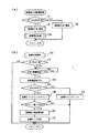
図2(a)に示す如く、吸気絞り弁制御処理は、S110(Sはステップを表す)にてイグニッションスイッチ20がオン状態であるか否かを判断し、オン状態であれば、S120にて、駆動装置16に開弁指令を出力することにより、吸気絞り弁10を全開状態まで開弁させ、オフ状態であれば、S130にて、駆動装置16に閉弁指令を出力することにより、吸気絞り弁10を全閉状態まで閉弁させる、といった手順で実行される。そして、S120にて吸気絞り弁10を開弁させた後は、S200に移行して、本発明にかかわる主要な処理である、故障判定処理を実行する。
【0024】
次に、図2(b)に示すように、S200で実行される故障判定処理では、まず、S210にて、ディーゼルエンジン2の始動状態か否かを判断する。すなわち、始動時に運転者により操作されるスタータスイッチ21からのオン・オフ状態を表す信号において、オン状態であるときに始動状態であると判断する。逆にオフ状態であるときには始動状態でないと判断すると、S230以降の判定処理を実行することなく、当該処理を終了する。
【0025】
次に、S210にて始動状態であると判断された場合に実行されるS230では、ディーゼルエンジン2の始動直後から所定期間経過したか否か、すなわち、予め設定された故障判定用の一定時間KTFLが経過したか否かを判断することにより、時間KTFLが経過するのを待ち、時間KTAFLが経過すると、S240に移行する。
【0026】
なお、本実施形態では、所定期間(故障判定用の一定時間KTFL)経過したときS230以降の判定処理を実行する構成で以下説明するが、所定期間経過するまでの間、連続的に判定処理を実行する構成としてもよい。また、後述するディーゼルエンジン2の始動時の吸気絞り弁10の閉状態に起因する吸気量の増加速度から判定する場合、所定期間を、始動直後の吸気量に応じて基準速度より算出される基準吸気量に達するまでの時間としてもよい(他の変形例の構成に相当)。
【0027】
S240では、そのとき(詳しくは、スタータスイッチ21をオンすることでディーゼルエンジン2を始動させるスタータを駆動した直後から所定時間KTAFLが経過したとき)吸気量センサ12にて検出されている吸気量AFSを取り込み、これをRAM30cの所定の記憶エリアに格納する。そして、続くS260では、RAM30cから読み出した吸気量AFSが、予め設定された故障判定値AFSFよりも小さいか否かを判断する。そして、S260にて否定判断されると(詳しくは吸気量AFSが故障判定値AFSF以上であれば)、S270に移行して、故障判定回数をカウントするための故障カウンタの値を初期値「0」にクリアした後、当該処理を終了し、逆に、S260にて肯定判定されると(詳しくは吸気量AFSが故障判定値AFSFよりも小さい場合には)、S280に移行して、故障カウンタの値をインクリメント(+1)した後、S290に移行する。なお、S210からS260の一連の処理は、本発明の故障判定手段に相当する。
【0028】
また次に、S290では、故障カウンタの値(カウント値)が、予め設定された故障判定回数KCAFL以下であれば、そのまま当該処理を終了し、逆に、故障カウンタによるカウント値が故障判定回数KCAFLより大きい場合には、S300にて、吸気絞り弁10が閉状態で故障(以下、閉故障と呼ぶ)していると判断してその旨を記憶した後、S310にて、故障ランプ22を点灯し、当該処理を終了する。なお、S280からS310の一連の処理は、本発明(詳しくは請求項6)の報知手段に相当する。
【0029】
以上説明したように、本実施形態では、イグニッションスイッチ20のオン操作と共に、駆動装置16に吸気絞り弁10を開弁するように開弁指定を出力した直後に故障判定処理(S200)を実行して、まず、スタータスイッチ21がオン状態(換言すれば、始動状態)であるか否かを判断して、オン状態であれば、図2に示すS230以降の故障判定処理を続行する。S230以降の故障判定処理において、図3に示すように、スタータスイッチ21をオン状態にすると共にディーゼルエンジン2を始動させるスタータを駆動させた直後(時刻t1)から所定時間KTAFLを経過したとき(時刻t2)の吸気量AFSを取り込み、この吸気量AFSが予め設定された故障判定値AFSFよりも小さいか否かを判断することにより、吸気絞り弁10の故障判定を行なう。この故障判定で吸気絞り弁10が故障状態であると判定され、複数回故障判定が連続すると故障ランプ22を点灯させて報知する。
【0030】
このため、吸気絞り弁10の故障に起因した始動不良であることを故障ランプ22の点灯により運転者等の車両乗員に報知できるので、運転者が始動を繰り返し試みることで発生するバッテリ上がり等の2次故障を防止することができる。さらに、運転者或いは使用者が故障だと判断して修理工場に持ち込んだ場合でも、修理工場で修理する際、故障状態を再現させずとも、故障ランプ22の点灯により吸気絞り弁10の故障であると特定することができる。
【0031】
なお、図3は、吸気絞り弁10の故障判定条件成立時(イグニッションスイッチ20のオン状態、およびスタータスイッチ21のオン状態)のエンジン回転数、吸気絞り弁10の開度、吸気量の変化を表すタイムチャートである。
【0032】
また、本実施形態によれば、吸気絞り弁10の故障判定するためには、ディーゼルエンジン2の始動直後から所定時間KTAFL経過したときに1回だけ、吸気量センサ12により検出された吸気量AFSを取り込むことによって故障判定できるので、故障判定装置を構成するECU30の負担を軽減できる。
【0033】
また更に、本実施形態によれば、吸気量AFSが故障判定値AFSFよりも小さいときに、吸気弁り弁10が故障したものとして故障ランプ22を点灯するのではなく、故障判定値AFSFを用いた吸気絞り弁10の故障判定手段により吸気絞り弁10の故障が判定された連続回数を故障カウンタを用いてカウントし、そのカウント値(換言すれば吸気絞り弁10の故障連続判定回数)が予め設定された故障判定回数KCAFLよりも大きくなった場合に、吸気絞り弁10を確実に故障しているものと判断して、その旨を記憶し、故障ランプ22を点灯させる。
【0034】
したがって、吸気量AFSから吸気絞り弁10の閉故障を誤判定したとしても、その判定結果に従い運転者等の車両乗員に対して誤って警報を発してしまうようなことはなく、故障ランプ22の点灯による警報の報知を正確に行ない、警報機能としての報知手段の信頼性を向上できる。
【0035】
(変形例)
吸気絞り弁10の故障判定をするには、ディーゼルエンジン2の始動時の吸気絞り弁10の閉状態に起因する吸気量の増加特性を検出して、基準増加特性(予め設定された所定値)と比較すればよく、例えば図4に示すように、始動直後に吸気量センサ12により検出された吸気量AFSLと、その後所定時間KTAFSL経過したときに吸気量センサ12により検出された吸気量AFSHとの偏差(AFSH−AFSL)を算出し、その算出された吸気量との偏差(変化量)が予め設定された判定値KDAFLより小さいときに、吸気絞り弁10の故障と判定してもよい。
【0036】
第1の実施形態のS230からS260の処理に代えて以下のように構成することができる。
【0037】
S210にて始動状態であると判断されるとS220が実行される。S220では、吸気量センサ12にて検出され、ディーゼルエンジン2を始動させるスタータを駆動させた直後の吸気量AFSLを取り込み、これをRAM30cの所定の記憶エリアに格納する。そして、続くS230では、吸気量AFSLを取り込んだ後、予め設定された故障判定用の一定時間KTAFLが経過したか否かを判断することにより、時間KTAFLが経過するのを待ち、時間KTAFLが経過すると、S240に以降する。
【0038】
S240では、そのとき吸気量センサ12にて検出されている吸気量AFSHを取り込み、これをRAM30cの所定の記憶エリアに格納する。そして、続くS250では、S220およびS240にてそれぞれ取り込んだ吸気量AFSLおよびAFSHをRAM30cから読み出し、これら各吸気量の偏差(AFSH−AFSL)を、吸気量の変化量として算出する。なお、S220からS250の一連の処理は、本発明(詳しくは請求項3)の吸気量差算出手段に相当する。
【0039】
そして、続くS265では、この算出された変化量が、予め設定された故障判定値KDAFLよりも小さいか否かを判断する、本発明(詳しくは請求項3)の判定手段としての処理を実行する。そして、S265にて否定判断されると、S270に移行し、逆に、S265にて肯定判定されると、S280に移行する。以降の処理は、第1の実施形態と同じである。
【0040】
また更に、他の変形例として、吸気量の増加速度から吸気絞り弁10の故障判定を行ってもよい。図2に示した故障判定処理において、S230からS260の処理に代えて、例えばスタータスイッチ21をオン状態にすることでディーゼルエンジン2を始動させるスタータを駆動させた直後に吸気センサ12にて検出されている吸気量を取り込み、その吸気量から所定値を減じた速度検出用の基準吸気量を設定する処理、および基準吸気量の設定後、吸気量センサ12にて検出される吸気量が基準吸気量に達するまでの時間を計測し、その計測時間が予め設定された故障判定時間を越えたか否かを判定する処理、からなる一連の処理を実行するようにし、この処理で、計測時間が故障判定時間を越えたと判定されると、吸気量の変化速度が故障判定速度より遅いと判断して、吸気絞り弁10の故障を判定する構成にしてもよい。
【0041】
(第2の実施形態)
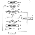
第2の実施形態として、以下図5を参照して説明する。図5は、故障判定処理を表すフローチャートである。
【0042】
本実施形態は、ディーゼルエンジン2の始動後吸気センサ12に検出される吸気量AFSTが予め設定された故障値AFSFより小さい期間が予め設定された所定時間KTAFLが経過する間継続する場合に絞り弁10の故障と判定する構成であり、第1の実施形態とは、S210の処理と、S230からS260の処理が異なる。
【0043】
S215は、前処理でイグニッションスイッチ20からのオン状態を表す信号からS200の故障判定処理に移行してから、まず、スタータスイッチ21等の状態から吸気絞り弁10の故障判定条件が成立しているか否かを判断する。この判定条件は、ディーゼルエンジン2が始動状態として準備ができているか否かを判断するためのものであり、例えば、
(1)運転者により操作されるスタータスイッチ21がオン状態であること。
【0044】
(2)運転者により操作されるスタータスイッチ21がオン状態であると共に、アクセルペダルの踏込み量が所定値以上あること。
【0045】
(3)運転者により操作されるスタータスイッチ21がオン状態であると共に、始動する直前のディーゼルエンジン2の冷却水温が所定温度より高いこと(換言すれば、燃料等が凍結して加熱ヒータ等を使用して暖めてからでないと即時始動できない温度状態(以下、極低温状態と呼ぶ)で車両が放置されていないこと)。
【0046】
といった複数の条件からなる。そして、S215では、これらの条件の全てが満足しているときに、ディーゼルエンジン2が始動状態として準備ができていると判断して、S267以降の判定処理を実行させて、逆にディーゼルエンジン2が始動状態として準備ができてないと判断すると、S267以降の判定処理を実行させることなく、当該処理を終了する。なお、S215の処理は、本発明の判定動作禁止手段に相当する(詳しくは、(3)が請求項5に対応)。
【0047】
次に、S215にて吸気絞り弁10の故障判定条件が成立していると判断された場合に実行されるS267は、吸気量センサ12にて検出されている吸気量AFSが予め設定された判定値AFSFより小さい状態となる期間が予め設定された所定時間KTAFLの間継続しているか否かを判断する。これにより、所定時間KTAFLが経過する期間に検出される吸気量AFSFをRAM30cに取り込み、全て記憶し保存する必要はない。例えば、吸気量センサ12にて検出されている吸気量AFSを取り込んでS267で処理するに要する期間をおくことで吸気量センサ12にて検出される吸気量AFSを順次5つ取り込めば、取り込んだ5つの吸気量AFS(1)、AFS(2)、AFS(3)、AFS(4)、AFS(5)は、判定される吸気量AFSより前に取り込んだ吸気量の値を記憶し保存し続けなくともS267の処理ができる。
【0048】
さらに、1回のディーゼルエンジン2の始動の度に取り込んだ複数の吸気量AFSTの観測結果から吸気絞り弁10の故障判定をするので、故障判定手段の信頼性を向上させると共に、吸気絞り弁10が故障状態であると判定して、運転者等の車両乗員に警報を発するように報知する報知手段を備えた吸気絞り弁判定装置の信頼性を向上できる。
【0049】
そして、S267にて否定判断されると、S270に移行し、逆に、S267にて肯定判定されると、S280に移行する。以降の処理は、第1の実施形態と同じである。
【0050】
なお、本実施形態では、運転者によるイグニッションスイッチ20のオン操作と共に実行する吸気絞り弁10の故障判定を行う条件として、上述の(1)〜(3)からなる故障判定条件を挙げ、これら各条件が全て成立した際に、吸気絞り弁10の故障判定を行うものとして説明したが、吸気絞り弁10の故障判定を行うか否かの判定は、ディーゼルエンジン2の始動状態が準備できていることを判定できればよいため、故障判定条件としては、例えば、上述(1)から(3)のうちのいずれか一項を選択して設定するようにしてもよく、或いは、他の条件を更に追加するようにしてもよい。
【0051】
また、実施形態では、吸気絞り弁10の故障を判定した際には、故障ランプ22を点灯させることにより、その旨を報知するものとして説明したが、吸気絞り弁10の故障の報知は、例えば、故障ランプ22を点滅させるとか、或いは、警報音を発するようにすれば、運転者等の車両乗員に対して、より速やかにかつより確実に異常を報知することができる。
【図面の簡単な説明】
【図1】本発明の第1の実施形態のディーゼルエンジンおよびその周辺装置を表す概略構成図である。
【図2】図1中のECUにて実行される吸気絞り弁制御処理および、故障判定処理を表すフローチャートである。
【図3】図1中のエンジン始動時のエンジン回転数、吸気絞り弁、および吸気量の挙動並びに吸気絞り弁の故障判定動作を説明するタイムチャートである。
【図4】変形例であり、ECUにて実行される故障判定処理を表すフローチャートである。
【図5】第2の実施形態となる吸気絞り弁故障判定装置で、ECUにて実行される故障判定処理を表すフローチャートである。
【符号の説明】
2 ディーゼルエンジン
4 吸気通路
6 燃料噴射弁
8 排気通路
10 吸気絞り弁
12 吸気センサ(吸気量検出手段)
14 アクチュエータ
16 駆動装置
18 回転数センサ
20 イグニッションスイッチ
21 スタータスイッチ
22 故障ランプ
30 電子制御装置(ECU)[0001]
BACKGROUND OF THE INVENTION
The present invention relates to an intake throttle valve failure determination device for determining a failure of an intake throttle valve (specifically, a failure in a closed state) in a diesel engine having an intake throttle valve in an intake passage.
[0002]
[Prior art]
Assuming that the diesel engine is equipped with an intake throttle valve, for example, an intake throttle valve that can be opened and closed via an actuator such as a motor is provided in the intake passage of the diesel engine to prevent overrun after operation stop. Those configured to close are known.
[0003]
[Problems to be solved by the invention]
In the conventional configuration as described above, for example, when the intake throttle valve has failed in the closed state, it is considered to promptly detect that the intake throttle valve has failed in the closed state and notify the secondary throttle to prevent the secondary failure. Not done. Therefore, even when the ignition switch is turned on and the starter switch is turned on to start the diesel engine under such a closed state failure, the engine may not start. In such a case, since the driver repeats trying to start many times, there is a possibility that the battery voltage of the vehicle is lowered and the battery may be increased in some cases.
[0004]
In addition, even when the driver determines that there is a failure, there is a problem that it cannot be determined whether or not the cause of the failure to start is a failure of the intake throttle valve when repairing at a repair shop.
[0005]
The present invention has been made in consideration of such circumstances, and its first object is to quickly detect and notify a malfunction of the intake throttle valve at the start, thereby protecting the battery and the like. An object of the present invention is to provide an intake throttle valve failure determination device for a diesel engine that makes it possible to specify that the cause of the failure of inability to start is a failure of the intake throttle valve.
[0006]
In addition, the second purpose is that it is always possible to accurately determine that the intake throttle valve has failed in the closed state, and to notify that the intake throttle valve is in the closed state. It is to provide a determination device.
[0007]
[Means for Solving the Problems]
According to claim 1 of the present invention, failure determination meansIs, Specified immediately after starting the diesel enginetimeUntil the lapsePeriodwhileInMonitoring the change in intake air amount detected by the intake air amount detection meansTo determine the failure of the intake throttle valve.When the intake air amount does not increase with a predetermined increase characteristic, a failure of the intake throttle valve is determined. In addition, when the failure determination unit determines that the intake throttle valve is in a failure state, the notification unit notifies the failure state. As a result, it is possible to quickly detect by monitoring the change state of the intake air amount during the start operation, and to notify the vehicle occupant such as the driver that the start failure is caused by the failure of the intake throttle valve. It is possible to prevent a secondary failure such as battery exhaustion that occurs when a person repeatedly tries to start.
[0008]
In addition, even if the driver determines that there is a malfunction and brings it to a repair shop, when repairing at the repair shop, it is necessary to identify the malfunction of the intake throttle valve based on the information provided by the notification means without reproducing the fault condition. Can do.
Further, according to the first aspect of the present invention, there is provided drive means for opening and closing the intake throttle valve, and the failure determination means detects the states of the ignition switch and the starter switch, and when the ignition switch is turned on, the intake throttle When a valve opening command is output to the valve drive means and the subsequent starter switch is turned on, a malfunction of the intake throttle valve is detected based on the intake air amount detected by the intake air amount detection means during the period. judge.
[0009]
Here, the failure determination means determines a failure of the intake throttle valve from a change state of the intake air amount immediately after the diesel engine is started and until a predetermined period elapses. Does not need to continuously monitor the change in the intake air amount after the diesel engine is started until a predetermined period elapses. For example, the failure determination means may be configured as described in
[0010]
In other words, according to the second aspect of the present invention, the malfunction of the intake throttle valve is determined when the intake air amount detected by the intake air amount detecting means is smaller than the predetermined value when a predetermined time has passed since the start of the diesel engine. Has been. Thus, in order to determine the failure of the intake throttle valve, the intake air amount detected by the intake air amount detecting means only needs to be taken in once when a predetermined time has passed immediately after the start of the diesel engine. For this reason, since it is not necessary to continuously monitor the intake air amount after the diesel engine is started until a predetermined period elapses, the burden on the circuit (for example, the engine control computer) constituting the failure determination device is reduced. Can be reduced.
[0011]
Similarly, the failure determination device may be configured as described in claim 3 or claim 4. According to the third aspect, the deviation between the intake air amount detected by the intake air amount detecting means immediately after the start of the diesel engine and the intake air amount detected by the intake air amount detecting means after a predetermined time has elapsed is calculated. When the deviation from the calculated intake air amount is smaller than a predetermined value by the determination means, the failure of the intake throttle valve is determined. According to the fourth aspect of the present invention, when the increasing speed of the intake air amount immediately after the start of the diesel engine is slower than a predetermined value, a failure of the intake throttle valve is determined. In other words, the intake throttle valve is detected by detecting the increase characteristic of the intake air amount due to the closed state of the intake throttle valve at the start of the diesel engine and comparing it with the reference increase characteristic (substitute with a predetermined value). Therefore, the same effect as that of the apparatus according to
[0012]
In addition, when it is determined that the intake throttle valve has failed as in the present invention, it is necessary to notify the vehicle occupant or the user such as a driver and prompt the inspection and repair of the intake throttle valve. Depending on how the vehicle equipped with is left unattended, it may be impossible to accurately determine the failure of the intake throttle valve.
[0013]
Therefore, as described in claim 5, the failure determination means further determines whether or not the diesel engine is in an extremely low temperature state, and if the diesel engine is in an extremely low temperature state, determines whether or not the intake throttle valve has failed. It is preferable to provide a prohibition operation prohibiting means. As a result, the engine such as the intake throttle valve freezes (hereinafter referred to as the icing state) when starting the vehicle early in the morning in a cold district, for example, in winter in Hokkaido, with the vehicle left unattended overnight. When the engine is at a very low temperature, the failure determination operation of the intake throttle valve is stopped, so the intake throttle valve cannot be operated due to the icing state, or the engine cannot be started due to light oil as fuel and freezing of the fuel control device Is not misjudged as a malfunction of the intake throttle valve. Since a normal vehicle is equipped with, for example, a heater as a cold district vehicle, the temperature rises and can be released from the icing state after a predetermined period of time has passed since the heater is operated. Is possible.
[0014]
In addition, when the failure determination means determines that the intake throttle valve has failed, if it is informed to issue an alarm to that effect, it will also notify when the failure determination means erroneously determines that the intake throttle valve is closed. As a result, the reliability of the notification means as an alarm function is lowered.
[0015]
For this reason, in order to notify the malfunction of the intake throttle valve, as described in claim 6, the notification means performs an intake throttle valve by a failure determination operation of the failure determination means that is executed every time the diesel engine is started. It may be configured to notify that the intake throttle valve is malfunctioning when it is determined a plurality of failures consecutively. As a result, when the malfunction of the intake throttle valve is determined a plurality of times in succession, notification is made so that when the malfunction determination means erroneously determines the malfunction of the intake throttle valve, an alarm indicating that is issued as it is. Can be prevented, and the reliability of the notification means as an alarm function can be improved.
[0016]
DETAILED DESCRIPTION OF THE INVENTION
Embodiments of a diesel engine intake throttle valve failure determination device of the present invention will be described below with reference to the drawings.
[0017]
(First embodiment)
FIG. 1 is a schematic configuration diagram showing an automotive diesel engine and its peripheral devices according to a first embodiment to which the present invention is applied.
[0018]
As shown in FIG. 1, the
[0019]
The intake throttle valve 10 can be switched at least from a fully closed state to a fully opened state or vice versa by an
[0020]
The detection signal from the intake air amount sensor 12 serving as the intake air amount detection means is a detection signal from the
[0021]
The ECU 30 is configured as a well-known microcomputer centering on the CPU 30a, the
[0022]
Hereinafter, the intake throttle valve control process executed by the ECU 30 will be described.
[0023]
As shown in FIG. 2A, in the intake throttle valve control process, it is determined in S110 (S represents a step) whether or not the
[0024]
Next, as shown in FIG. 2B, in the failure determination process executed in S200, first, in S210, it is determined whether or not the
[0025]
Next, in S230, which is executed when it is determined in S210 that the engine is in the starting state, whether or not a predetermined period has elapsed since the start of the
[0026]
In the present embodiment, a description will be given below of a configuration in which the determination process after S230 is executed when a predetermined period (a fixed time KTFL for failure determination) has elapsed, but the determination process is continuously performed until the predetermined period elapses. It may be configured to execute. Further, when determining from the increasing speed of the intake air amount due to the closed state of the intake throttle valve 10 at the time of starting the
[0027]
In S240, the intake air amount AFS detected by the intake air amount sensor 12 at that time (specifically, when a predetermined time KTAFL has passed since the starter that starts the
[0028]
Next, in S290, if the value of the failure counter (count value) is equal to or smaller than the preset failure determination number KCAFL, the process is terminated, and conversely, the count value of the failure counter is determined to be the failure determination number KCAFL. If larger, in S300, it is determined that the intake throttle valve 10 is in a closed state and has failed (hereinafter referred to as a closed failure), and this is stored, and in S310, the
[0029]
As described above, in this embodiment, when the
[0030]
For this reason, since it is possible to notify the vehicle occupant such as the driver by starting the
[0031]
FIG. 3 shows changes in the engine speed, the opening degree of the intake throttle valve 10 and the intake air amount when the failure determination condition for the intake throttle valve 10 is satisfied (the
[0032]
Further, according to the present embodiment, in order to determine the failure of the intake throttle valve 10, the intake air amount AFS detected by the intake air amount sensor 12 is only once when the predetermined time KTAFL has passed since the start of the
[0033]
Furthermore, according to the present embodiment, when the intake air amount AFS is smaller than the failure determination value AFSF, the failure determination value AFSF is used instead of turning on the
[0034]
Therefore, even if it is erroneously determined that the intake throttle valve 10 is closed from the intake air amount AFS, a warning is not erroneously issued to a vehicle occupant such as a driver according to the determination result. It is possible to accurately notify the alarm by lighting, and improve the reliability of the notification means as an alarm function.
[0035]
(Modification)
In order to determine whether or not the intake throttle valve 10 has failed, an increase characteristic of the intake air amount due to the closed state of the intake throttle valve 10 when the
[0036]
It can replace with the process of S230 to S260 of 1st Embodiment, and can comprise as follows.
[0037]
If it is determined in S210 that the engine is in the starting state, S220 is executed. In S220, the intake air amount AFSL immediately after driving the starter for starting the
[0038]
In S240, the intake air amount AFSH detected at that time by the intake air amount sensor 12 is taken in and stored in a predetermined storage area of the
[0039]
In the subsequent S265, the processing as the determining means of the present invention (specifically, claim 3) is executed to determine whether or not the calculated change amount is smaller than a preset failure determination value KDAFL. . If a negative determination is made in S265, the process proceeds to S270. Conversely, if a positive determination is made in S265, the process proceeds to S280. The subsequent processing is the same as in the first embodiment.
[0040]
Furthermore, as another modification, the failure determination of the intake throttle valve 10 may be performed from the increasing speed of the intake air amount. In the failure determination process shown in FIG. 2, instead of the process from S230 to S260, for example, the
[0041]
(Second Embodiment)
A second embodiment will be described below with reference to FIG. FIG. 5 is a flowchart showing the failure determination process.
[0042]
In the present embodiment, the throttle valve is used when a period in which the intake air amount AFST detected by the intake sensor 12 after starting the
[0043]
In S215, after shifting from the signal indicating the ON state from the
(1) The
[0044]
(2) The
[0045]
(3) The
[0046]
It consists of a plurality of conditions. In S215, when all of these conditions are satisfied, it is determined that the
[0047]
Next, S267, which is executed when it is determined in S215 that the failure determination condition for the intake throttle valve 10 is satisfied, is a determination that the intake air amount AFS detected by the intake air amount sensor 12 is preset. It is determined whether or not the period during which the state is smaller than the value AFSF continues for a predetermined time KTAFL set in advance. Thus, the intake air amount AFSF detected during the period when the predetermined time KTAFL elapses is taken into the
[0048]
Further, since the failure determination of the intake throttle valve 10 is made based on the observation results of the plurality of intake air amounts AFST taken every time the
[0049]
If a negative determination is made in S267, the process proceeds to S270. Conversely, if a positive determination is made in S267, the process proceeds to S280. The subsequent processing is the same as in the first embodiment.
[0050]
In the present embodiment, the failure determination conditions including the above (1) to (3) are given as conditions for performing the failure determination of the intake throttle valve 10 that is executed together with the turning-on operation of the
[0051]
Further, in the embodiment, it has been described that when the failure of the intake throttle valve 10 is determined, the
[Brief description of the drawings]
FIG. 1 is a schematic configuration diagram showing a diesel engine and its peripheral devices according to a first embodiment of the present invention.
FIG. 2 is a flowchart showing an intake throttle valve control process and a failure determination process executed by the ECU in FIG.
FIG. 3 is a time chart for explaining the behavior of the engine speed, the intake throttle valve, and the intake air amount at the time of starting the engine in FIG. 1 and the failure determination operation of the intake throttle valve.
FIG. 4 is a flowchart showing a failure determination process executed by the ECU, which is a modified example.
FIG. 5 is a flowchart showing a failure determination process executed by an ECU in the intake throttle valve failure determination device according to the second embodiment.
[Explanation of symbols]
2 Diesel engine
4 Intake passage
6 Fuel injection valve
8 Exhaust passage
10 Inlet throttle valve
12 Intake sensor (Intake amount detection means)
14 Actuator
16 Drive device
18 Speed sensor
20 Ignition switch
21 Starter switch
22 Fault lamp
30 Electronic control unit (ECU)
Claims (6)
前記ディーゼルエンジンへの吸入空気量を検出する吸気量検出手段と、
前記ディーゼルエンジンの始動直後から所定時間経過するまでの期間において、前記吸気量検出手段にて検出される吸入空気量の変化状態を監視することにより前記吸気絞り弁の故障を判定する故障判定手段であって、該吸入空気量が所定の増加特性で増加していないときに、前記吸気絞り弁の故障を判定する故障判定手段と、
該故障判定手段により故障状態であると判定されると故障状態を報知する報知手段と、
前記吸気絞り弁を開閉する駆動手段と、
を備え、
前記故障判定手段は、
イグニッションスイッチ及びスタータスイッチの状態を検出し、前記イグニッションスイッチがON状態となったときに、前記吸気絞り弁の前記駆動手段に開弁指令を出力し、
その後の前記スタータスイッチがON状態となったときに、前記期間において前記吸気量検出手段にて検出される吸入空気量とに基づいて前記吸気絞り弁の故障を判定することを特徴とするディーゼルエンジンの吸気絞り弁故障判定装置。In a diesel engine having an intake throttle valve in an intake passage, an intake throttle valve failure determination device for determining failure of the intake throttle valve,
An intake air amount detecting means for detecting an intake air amount to the diesel engine;
Wherein in the period from immediately after starting of the diesel engine until a predetermined time elapses, it determines failure determining means a failure of the intake throttle valve by monitoring the change in state of the intake air amount detected by the intake air amount detecting means And when the intake air amount does not increase with a predetermined increase characteristic, failure determination means for determining failure of the intake throttle valve;
Informing means for informing the failure state when the failure judging means determines that the failure state is present;
Drive means for opening and closing the intake throttle valve;
With
The failure determination means includes
Detecting the state of the ignition switch and the starter switch, and when the ignition switch is turned on, outputs a valve opening command to the drive means of the intake throttle valve,
A diesel engine characterized in that a failure of the intake throttle valve is determined based on an intake air amount detected by the intake air amount detecting means during the period when the starter switch thereafter is turned on. Intake throttle valve failure determination device.
該吸入空気量差算出手段にて算出された前記吸入空気量の偏差が小さいときに、前記吸気絞り弁の閉状態での故障を判定する判定手段とを備えたことを特徴とする請求項1に記載のディーゼルエンジンの吸気絞り弁故障判定装置。The failure determination means takes in the intake air amount detected by the intake air amount detection means immediately after starting the diesel engine and when a predetermined time has passed thereafter, and calculates a deviation of the intake air amount taken in An intake air amount difference calculating means for
2. The apparatus according to claim 1, further comprising a determining unit that determines a failure in a closed state of the intake throttle valve when a deviation in the intake air amount calculated by the intake air amount difference calculating unit is small. An intake throttle valve failure determination device for a diesel engine according to claim 1.
Priority Applications (1)
| Application Number | Priority Date | Filing Date | Title |
|---|---|---|---|
| JP2000113965A JP4200633B2 (en) | 2000-04-14 | 2000-04-14 | Diesel engine intake throttle valve failure determination device |
Applications Claiming Priority (1)
| Application Number | Priority Date | Filing Date | Title |
|---|---|---|---|
| JP2000113965A JP4200633B2 (en) | 2000-04-14 | 2000-04-14 | Diesel engine intake throttle valve failure determination device |
Publications (2)
| Publication Number | Publication Date |
|---|---|
| JP2001295670A JP2001295670A (en) | 2001-10-26 |
| JP4200633B2 true JP4200633B2 (en) | 2008-12-24 |
Family
ID=18625848
Family Applications (1)
| Application Number | Title | Priority Date | Filing Date |
|---|---|---|---|
| JP2000113965A Expired - Fee Related JP4200633B2 (en) | 2000-04-14 | 2000-04-14 | Diesel engine intake throttle valve failure determination device |
Country Status (1)
| Country | Link |
|---|---|
| JP (1) | JP4200633B2 (en) |
Cited By (1)
| Publication number | Priority date | Publication date | Assignee | Title |
|---|---|---|---|---|
| US10273924B2 (en) | 2015-12-08 | 2019-04-30 | Hyundai Motor Company | Apparatus for controlling mild hybrid vehicle and method of using the mild hybrid vehicle |
Families Citing this family (2)
| Publication number | Priority date | Publication date | Assignee | Title |
|---|---|---|---|---|
| JP5566420B2 (en) * | 2012-05-11 | 2014-08-06 | 矢崎エナジーシステム株式会社 | Gas alarm |
| JP6625893B2 (en) * | 2016-02-12 | 2019-12-25 | 日野自動車株式会社 | Throttle valve abnormality judgment device |
-
2000
- 2000-04-14 JP JP2000113965A patent/JP4200633B2/en not_active Expired - Fee Related
Cited By (1)
| Publication number | Priority date | Publication date | Assignee | Title |
|---|---|---|---|---|
| US10273924B2 (en) | 2015-12-08 | 2019-04-30 | Hyundai Motor Company | Apparatus for controlling mild hybrid vehicle and method of using the mild hybrid vehicle |
Also Published As
| Publication number | Publication date |
|---|---|
| JP2001295670A (en) | 2001-10-26 |
Similar Documents
| Publication | Publication Date | Title |
|---|---|---|
| US6240774B1 (en) | System for detecting malfunction of internal combustion engine radiator | |
| US7774110B2 (en) | Failure diagnosis apparatus for vehicle | |
| JPH0777110A (en) | Failure detector of exhaust recirculation system | |
| JP3879368B2 (en) | Engine system abnormality determination device | |
| US6945035B2 (en) | Auxiliary air supplying system, and control methods and failure diagnostic methods thereof | |
| JP3338728B2 (en) | Method and apparatus for controlling secondary air supply to exhaust gas of an internal combustion engine | |
| JP4062765B2 (en) | Failure detection device for air-fuel ratio detection device | |
| US7073321B2 (en) | Controller for internal combustion engine | |
| JP4123627B2 (en) | Failure diagnosis device for engine temperature detection means | |
| US7085671B2 (en) | Abnormality detection apparatus of engine temperature adjusting thermostat | |
| JP4200633B2 (en) | Diesel engine intake throttle valve failure determination device | |
| KR910005478B1 (en) | Diagnostic device of control system for automobile | |
| US20020007669A1 (en) | Abnormality testing apparatus for engine system | |
| JP4635264B2 (en) | Abnormality judgment device | |
| JP3642169B2 (en) | EGR diagnosis device for engine | |
| EP2742217B1 (en) | Internal combustion engine control apparatus and internal combustion engine control method | |
| JP2001173503A (en) | Trouble deciding device for diesel engine take throttle valve | |
| KR100552791B1 (en) | method for checking rationality of O2 sensor in OBD system | |
| JP3975436B2 (en) | Abnormality diagnosis device for exhaust gas sensor | |
| JPH09329062A (en) | Abnormality judging device for exhaust gas recirculating device | |
| US20240077011A1 (en) | Removal determination device for exhaust gas purification device | |
| JP3186339B2 (en) | Hot wire air flow meter abnormality detection device | |
| JPH06101561A (en) | Device for detecting abnormality of vehicle speed detection means | |
| JPH11344465A (en) | Trouble diagnostic apparatus of heater for sensor | |
| JP3826440B2 (en) | Engine temperature sensor abnormality determination method |
Legal Events
| Date | Code | Title | Description |
|---|---|---|---|
| A621 | Written request for application examination |
Free format text: JAPANESE INTERMEDIATE CODE: A621 Effective date: 20060531 |
|
| RD01 | Notification of change of attorney |
Free format text: JAPANESE INTERMEDIATE CODE: A7421 Effective date: 20070427 |
|
| A131 | Notification of reasons for refusal |
Free format text: JAPANESE INTERMEDIATE CODE: A131 Effective date: 20080513 |
|
| A521 | Written amendment |
Free format text: JAPANESE INTERMEDIATE CODE: A523 Effective date: 20080711 |
|
| TRDD | Decision of grant or rejection written | ||
| A01 | Written decision to grant a patent or to grant a registration (utility model) |
Free format text: JAPANESE INTERMEDIATE CODE: A01 Effective date: 20080916 |
|
| A01 | Written decision to grant a patent or to grant a registration (utility model) |
Free format text: JAPANESE INTERMEDIATE CODE: A01 |
|
| A61 | First payment of annual fees (during grant procedure) |
Free format text: JAPANESE INTERMEDIATE CODE: A61 Effective date: 20080929 |
|
| R150 | Certificate of patent or registration of utility model |
Free format text: JAPANESE INTERMEDIATE CODE: R150 |
|
| FPAY | Renewal fee payment (event date is renewal date of database) |
Free format text: PAYMENT UNTIL: 20111017 Year of fee payment: 3 |
|
| LAPS | Cancellation because of no payment of annual fees |