JP4200620B2 - Washed rice cooker - Google Patents

Washed rice cooker Download PDF

Info

Publication number
JP4200620B2
JP4200620B2 JP2000002741A JP2000002741A JP4200620B2 JP 4200620 B2 JP4200620 B2 JP 4200620B2 JP 2000002741 A JP2000002741 A JP 2000002741A JP 2000002741 A JP2000002741 A JP 2000002741A JP 4200620 B2 JP4200620 B2 JP 4200620B2
Authority
JP
Japan
Prior art keywords
rice
water
drainage
valve
drain opening
Prior art date
Legal status (The legal status is an assumption and is not a legal conclusion. Google has not performed a legal analysis and makes no representation as to the accuracy of the status listed.)
Expired - Fee Related
Application number
JP2000002741A
Other languages
Japanese (ja)
Other versions
JP2001190408A (en
Inventor
喜八郎 長谷
正博 山崎
Current Assignee (The listed assignees may be inaccurate. Google has not performed a legal analysis and makes no representation or warranty as to the accuracy of the list.)
Iseki and Co Ltd
Original Assignee
Iseki and Co Ltd
Priority date (The priority date is an assumption and is not a legal conclusion. Google has not performed a legal analysis and makes no representation as to the accuracy of the date listed.)
Filing date
Publication date
Application filed by Iseki and Co Ltd filed Critical Iseki and Co Ltd
Priority to JP2000002741A priority Critical patent/JP4200620B2/en
Publication of JP2001190408A publication Critical patent/JP2001190408A/en
Application granted granted Critical
Publication of JP4200620B2 publication Critical patent/JP4200620B2/en
Anticipated expiration legal-status Critical
Expired - Fee Related legal-status Critical Current

Links

Images

Description

【0001】
【発明の属する技術分野】
この発明は、貯米部に貯留している米を自動計量・洗浄し、その後炊飯する洗米炊飯装置に関する。
【0002】
【従来の技術】
洗浄タンクの下端部に、洗浄した米と水加減した炊飯用の水とを下方に案内して排出し、さらに、洗浄時に生じた汚水を横側壁に設けた排水口から排出できるジャケットを設けている。そして、水加減をするためにジャケットの横壁壁に排水口に並んで小径の水加減用の排水口を設けている。
【0003】
【発明が解決しようとする課題】
然し乍ら、排水口を複数設けるものにあっては、排水口開閉弁もそれぞれの排水口に対応するために複数設ける必要があり、そのため、構成が複雑になるとともにコスト高の要因になる。
【0004】
【課題を解決するための手段】
この発明は、このような課題を解決する洗米炊飯装置を提供するものであって、つぎのような技術的手段を講じた。すなわち、請求項1では、貯米部(A)と下方に向けて米を案内可能なジャケット(1)を設けた洗浄部(B)と炊飯器(2)を設けている炊飯部(C)とを上側からその順に配置し、該ジャケット(1)から下方の炊飯器(2)に米および炊飯用の水を案内できるとともに横側壁(3)に設けた排水口(4)を開閉する排水口開閉弁(5)を設け、該排水口開閉弁(5)は3個の通路を有する3方向弁とし、排水口開閉弁(5)は排水口(4)からの排水を多量排水、少量排水または排水阻止の状態に切り替え可能に構成し、多量排水時には2箇所の通路(55,56)から排出する構成とし、少量排水時には1箇所の通路から排水する構成とし、該少量排水時に排水が通過する通路(55)に流量センサ(6)を設けたことを特徴とする洗米炊飯装置とした。
0005
【0006】
【作用】
炊飯作業について説明すると、炊飯台を設定位置まで引き出して炊飯器2を載せ、つぎに、炊飯台を元の位置に押し込んだ後、作業条件設定手段を操作して、所望の炊飯量、水加減、洗い方等の作業条件を設定すると、この作業条件は、制御手段に取り込まれる。
【0007】
そして、スタ−トスイッチを入りにし、炊飯作業を開始すると、貯米部Aに貯留している米は洗浄部Bの洗浄タンクに供給されて撹拌手段や給水手段などの洗浄手段により洗浄される。洗浄時に生じた汚水は排水口開閉弁5によって多量排水の状態にある排水口4から排水される。
【0008】
洗浄作業を終えると、排水口開閉弁5は排水口4を排水阻止の状態にするので、供給される水は洗浄タンクに貯留される。その後、所定量の水が洗浄タンクに溜ると、排水口開閉弁5は排水口4を少量排水の状態にするので、洗浄タンクからジャケット1、排水口4を通って排水される。
【0009】
そして、所定時間を経て所定の炊飯用の水量になると、排水口開閉弁5は排水口4を排水阻止状態にする。洗浄を終えた米は洗浄タンク、ジャケット1をとおって排出され、炊飯用の水とともに下方の炊飯器2に収容され、炊飯される。このように、一個の排水口開閉弁5の動作により、洗浄時に生じた汚水の排出、水加減時の排水および炊飯用の水の貯留を行なうことができる。
【0010】
排水口開閉弁5の3個の通路を介して汚水の排出、水加減時の排水および炊飯用の水の貯留を行なうことができるので、弁の切り替えによる作動でできる。さらに、通路の1か所に設けた流量センサ6が水加減時の排水量を検出するので、水加減の精度を高めることができる。
【0011】
【効果】
排水口開閉弁(5)は3個の通路を有する3方向弁とし、排水口開閉弁(5)は排水口(4)からの排水を多量排水、少量排水または排水阻止の状態に切り替え可能に構成し、多量排水時には2箇所の通路(55,56)から排出する構成とし、少量排水時には1箇所の通路から排水する構成とし、洗浄時に生じた汚水の排出、水加減時の排水および炊飯用の水の貯留を行なう排水構成が簡単で安価にすることができる。そして、弁の切り替えによる作動でできるので、簡単に構成することができる。さらに、少量排水時に排水が通過する通路(55)に流量センサ(6)を設けたことで水加減の精度を高めることができる。
【0012】
【発明の実施の形態】
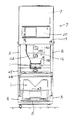
以下、本発明の実施の形態を図面に基づいて具体的に説明する。まず、その構成について説明すると、洗米炊飯装置7はフレ−ムFに貯米部Aと洗浄部Bと炊飯部Cとを上側からその順に配設し、炊飯部Cの炊飯器2を載せる炊飯台8を前後方向に移動可能に設けている。
【0013】
そして、この貯米部Aは下端部を連通口を有する天板の上面に着脱自在に設けるとともに前壁部に前後方向に開閉自在(作業時は閉じ位置)に設けて扉を形成したケ−ス9と、ケ−ス9に内装している漏斗10、モ−タ11,12,13、給水管15等を備えている。
【0014】
後述する洗浄用タンク16と連通口を介して連通する連通路には、外面の一部に受け孔17を有しモ−タ11からの回転動力により回転可能に設けている円筒形の給米体18を備えている。19は貯米部4の前壁部の右下方部に設けた電源スイッチである。
【0015】
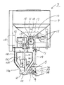
洗浄部Bは下部を細く形成し且つ円筒形状であって天板の下面に着脱自在に取り付けている中空の洗浄タンク16と、該洗浄タンク16の中央部に設けた撹拌装置20と、洗浄タンク16の下端部に着脱自在に取り付けたジャケット1の排米口21を開閉する投下弁22等を備えている。
【0016】
洗浄タンク16は円筒の中間部から下端に向かって先細に形成した斜面部16bを形成しており、そして、縦方向においては円筒部16aの中間部から斜面部の上端に至る間と斜面部16bの上端から中間部にかけ、横方向においては円周方向の略前半部に至る孔16cを設けている。16dは前記孔16cよりも大きな平板で形成した蓋であり、該蓋16dは上下の各端部で且つ左右各端部に設けた取付け具(実施例ではパッチン錠を使用)16eにより円筒部16aおよび斜面部16bに着脱可能に設けている。
【0017】
したがって、洗浄タンク16の点検あるいは清掃等のメンテナンスを行なうとき、蓋16dを除去して孔16cを開放すると、この露出する大きい孔16cから洗浄タンク16の内壁や撹拌装置20のメンテナンスを容易に行なうことができる。
【0018】
そして、該撹拌装置20はモ−タ12を駆動源として回転可能に設け且つ縦方向に軸芯を有する中空の撹拌軸23と、該撹拌軸23に取付けた撹拌体24とを具備している。操作パネル25は炊飯量、水加減、洗い方、浸漬時間、むらし時間、一釜・まとめ・連続の炊飯モ−ドを設定するスイッチ等の炊飯条件を設定する各種のスイッチを配置したスイッチ部47、時計、テスト、計量、洗米、上水、下水、水位、排水、投下、リセットなどの手動操作による作業を行い得るスイッチ49、予約タイマ−による時・分設定スイッチ、曜日指定スイッチ、ヘルプスイッチ、予定釜数スイッチ、予約中、現在時刻、累計釜数、曜日、炊飯作業状態などを表示する表示部48、スタ−トスイッチ26などを設けている。
【0019】
なお、該操作パネル25に設けた各スイッチの操作による作業条件は必要なデ−タや制御プログラム等を内蔵するメモリを有するマイクロコンピュ−タの演算制御部(制御手段、以下「CPU」と呼ぶ)27に取り込まれ、また、駆動等の制御信号が出力される構成としている。
【0020】
投下弁22はモ−タ13を駆動源とし撹拌軸23の内部を昇降する弁軸28の下端部に着脱自在に設けており、また、洗浄タンク16の上部にはオ−バ−フロ−管29により排水箱30と連通している矩形上のオ−バ−フロ−口31を設けている。
【0021】
ジャケット1は横端部を前記排水箱30を着脱自在に設けているとともに排水箱の横側壁3に排水箱30と連通可能な円形状の排水口4を設けている。32は排水口4を開閉する排水口開閉弁5を作動する開閉弁作動機構であって、モ−タ33により回転するモ−タ軸34の先端部に着脱自在に取り付けたカム35、該カム35に接触する頭部36を備え且つ排水箱30の軸受体37に横方向に摺動可能に設けた開閉弁軸38等を備えている。
【0022】
該排水口開閉弁5は開閉弁軸38の先端部に着脱自在に設けており、開閉弁軸38が最も前進したときに、排水口4を貫通するとともに排水口4よりも小径に形成した開閉弁体39と、外径が排水口4よりも大きい可撓性(例えばゴム、樹脂等)の円筒状に形成し且つ開閉弁体39の外周部に着脱可能に嵌入し密着させた円筒体40とを備えている。なお、該開閉弁体39と円筒体40とを可撓性を有する部材により一体成形してもよいことはもちろんである。41は開閉弁軸38に遊嵌し、軸受体37と頭部36との間に設けた戻しばねであって、該頭部36を常時カム側に押圧する。
【0023】
そして、モ−タ33のモ−タ軸34が1回転する間に、カム35と排水口開閉弁5との関係は図6乃至9に示すようにA,B,C,Dの4工程を有している。すなわち、モ−タ軸34が1回転する間に、回転方向に向かって工程A,工程B,工程C,工程Dの順に作業があり、再び工程Aに戻る構成である。
【0024】
工程Aでは、カム35が開閉弁軸38の頭部36に対し押圧していないので、戻しばね41の押圧力を受けた頭部36とともに開閉弁軸38はカム側の所定位置で停止し、これにより、排水口開閉弁5は排水口4を「全開」の状態にする。工程Bでは、カム35が戻しばね41を圧縮しながら頭部36を押して開閉弁軸38を最も前進させているので、排水口開閉弁5は排水口4を「全閉」の状態にする。
【0025】
工程Cでは、戻しばね41またはカム35により頭部36を押圧して開閉弁軸38を中間に位置させているので、排水口開閉弁5は排水口4を「半閉」の状態にする。工程Dでは、カム35が戻しばね41を圧縮しながら頭部36を押圧して開閉弁軸38を最も前進させているので、排水口開閉弁5は排水口4を「全閉」の状態にしている。
【0026】
なお、モ−タ33はCPU27からの駆動指令信号により、図示していないがリミットスイッチ50,51,52,53により工程A乃至工程Dを選択できる,ように構成している。42は一端部を排水箱37に接続し、他端部を排水路にのぞませている排水パイプである。
【0027】
前記給水管15は途中部に排水側からチェック弁、電磁弁の順に設けて給水源に連通可能に設けて天板を通って洗浄タンク内にのぞませ、先端部に水を拡散供給するノズルを備えた構成としている。炊飯部Cは外釜43と内釜44と炊飯蓋45からなる炊飯器2と加熱源(例えば、ガスコンロ)を載せ且つ前後方向に移動可能に設けた炊飯台8とを備えており、手動または自動で点火する構成である。なお、該実施例では、CPU27からの点火指令信号により自動点火する構成としている。
【0028】
図17のブロック回路を説明すると、CPU27は算術、論理及び比較演算作業などを行う。そして、該CPU27に入力インタ−フェイス46を介して入力される多種の情報の中で、主な情報としては、操作パネル25のスイッチ部47に設けている炊飯量、水加減、洗い方、浸漬時間、むらし時間、一釜・まとめ・連続、点火(手動・自動)を設定する各スイッチからの炊飯情報、手動操作による作業選択情報、電源スイッチ19からの電源入り切り情報、スタ−トスイッチ26からの作業開始情報およびリミットスイッチ50,51,52,53からのモ−タ停止情報等がある。
【0029】
また、出力インタ−フェイス54を介してCPU27から出力される多種情報の中で、主な情報としては、モ−タ11,12,13,14,33への駆動指令信号、電磁弁への開閉指令信号、操作パネル25に設けた表示部48への報知指令信号などがある。
【0030】
つぎに、その作用について説明すると、まず、作業条件を設定する場合、電源スイッチ19を入りにして通電し、そして、操作パネル25に設けたスイッチ部47の炊飯量スイッチ等各種スイッチを操作して炊飯量、水加減、洗い方、浸漬時間、むらし時間、一釜・まとめ・連続の炊飯モ−ドを設定すると、選択した作業条件は入力インタ−フェイス46を介してCPU27に取り込まれる。
【0031】
作業の準備を終え、スタ−トスイッチ26を入りにすると、CPU27は制御プログラムのフロ−に基づき作業が行われるが、まず、CPU27は出力インタ−フェイス54を介してモ−タ11に駆動指令信号を出力して起動し、給米体18を回転させて貯米部Aの漏斗10に貯留している米を定量供給する。
【0032】
つぎに、CPU27は出力インタ−フェイス54を介して電磁弁に「開」信号を出力し、また、モ−タ12に駆動指令信号を出力して起動するので、給水源から送られてきた水は給水管15・チェック弁を通って洗浄タンク16に散水すると共に撹拌軸23と撹拌体24は回転してこの水及び米を撹拌し洗浄する。さらに、リミットスイッチ50による停止信号を、入力インタ−フェイス46を介して入力しているCPU27は、出力インタ−フェイス54を介してモ−タ33に駆動指令信号を出力しないので、排水口開閉弁5は排水口4を開放している(工程A)。
【0033】
したがって、該洗浄作業時に生じた汚水は洗浄タンク16からジャケット1、排水口4を通って排水箱30に入り、その後、排水パイプ42を通って機外に排出される。洗浄作業を終えると、出力インタ−フェイス54を介して出力していたCPU27の駆動指令信号は停止されるので、電磁弁が閉じると共に、モ−タ12の駆動を停止するので、給水と撹拌の両作業を停止する。
【0034】
洗浄タンク16に貯留している水が排水されると(時間で管理している)、CPU27は出力インタ−フェイス54を介して励磁信号を出力して電磁弁を開放し、また、リミットスイッチ50の停止信号に優先してモ−タ33に駆動指令信号を出力しモ−タ軸34とカム35を回転する。そして、該モ−タ軸34が所定位置まで回転すると、リミットスイッチ51が入りになるので、入力インタ−フェイス46を介して、停止情報を取り込んだCPU27はモ−タ33への駆動指令信号の出力を停止するので、モ−タ33、モ−タ軸34およびカム35は停止する。
【0035】
これに関連して、カム35は戻しばね41を圧縮しながら頭部36を押して軸受体37によって摺動案内される開閉弁軸38を最も前進させているので、排水口開閉弁5は排水口4を「全閉」の状態にする(工程B)。したがって、給水源から送られてきた水は給水管15からチェック弁を通って先端部のノズルから洗浄タンク16に供給されて貯留される。そして、貯留した水の水位がオ−バ−フロ−口31に到達すると(図示していないが、満水センサにより検出可能に設けており、CPU27が入力インタ−フェイス46を介して満水情報を取り込む構成に設けている。)、CPU27は出力インタ−フェイス54を介して出力していた励磁信号を停止するので、電磁弁は「閉じ」になって清水の給水作業を終了する。
【0036】
つぎに、CPU27は出力インタ−フェイス54を介してリミットスイッチ51の停止信号に優先してモ−タ33に駆動指令信号を出力して駆動する。そして、リミットスイッチ52が入りになると、入力インタ−フェイス46を介して停止情報を取り込んだCPU27は、モ−タへの駆動指令信号の出力を停止する。
【0037】
これに関連して、戻しばね41またはカム35により頭部36を押圧して開閉弁軸38を中間に位置させているので、排水口開閉弁5は排水口4を「半閉」の状態にする(工程C)。すると、洗浄タンク16に貯留している炊飯用の清水はジャケット1から半閉じの排水口4を通って排水箱30に入り、排水パイプ42によって所定の排水場所に案内される。
【0038】
所定時間後、CPU27はリミットスイッチ52の停止信号に優先してモ−タ33に駆動指令信号を出力してモ−タ軸34とカム35を回転する。そして、該モ−タ軸34が所定位置まで回転すると、リミットスイッチ53が入りになるので、入力インタ−フェイス46を介して、停止情報を取り込んだCPU27はモ−タ33への駆動指令信号の出力を停止するので、モ−タ33、モ−タ軸34およびカム35は停止する。
【0039】
これに関連して、カム35が戻しばね41を圧縮しながら頭部36を押圧して開閉弁軸38を最も前進させているので、排水口開閉弁5は排水口4を「全閉」の状態にしている(工程D)。したがって、洗浄タンク16に貯留している炊飯用の清水は設定した供給米量(炊飯量)および水加減(硬さ)に対応する水量であり、この関係は予めテストにより計量したデ−タをメモリに内蔵している。
【0040】
このとき、排水口から排水される清水は洗浄時に生じた汚水が排水口4から排水される単位時間あたりの排出量が少量であるので、排水時間を長くとれ、水加減精度を向上することができる。また、汚水の排出時には、排水口4からの単位時間あたりの排出量を多くすることができるので、洗浄に関連する作業時間の短縮を図れ作業能率を向上する。
【0041】
つぎに、米を洗浄タンク内で所定時間の全部あるいは一部を浸漬すると、CPU27はモ−タ13に駆動指令信号を所定時間出力して駆動した後にモ−タ13への駆動指令信号の出力を停止し、つづいて、停止状態を所定時間保持した後に再びモ−タ13に駆動指令信号を所定時間出力した後、出力を停止する。
【0042】
この間、弁軸28及び投下弁22は下降して排米口21を開放するので、洗浄タンク16の米と水はジャケット1の排米口21を通って落下して下方の炊飯器2の内釜44に収容される。排米後、弁軸28と投下弁22とは元の位置に戻って排米口21を閉じる。その後、CPU27から出力した点火信号により自動点火されて炊飯を開始され、つづいて、蒸らし時間が経過すると炊飯作業を終了する。
【0043】
また、弁軸28と投下弁22とが元の位置に戻ると、このタイミングに合わせて、CPU27から出力インタ−フェイス54を介してリミットスイッチ53の停止信号に優先してモ−タ33に駆動指令信号を出力しモ−タ軸34とカム35を回転する。そして、該モ−タ軸34が所定位置まで回転(一回転)すると、リミットスイッチ50が入りになるので、入力インタ−フェイス46を介して、停止情報を取り込んだCPU27はモ−タ33への駆動指令信号の出力を停止するとともにモ−タ33、モ−タ軸34およびカム35も停止する。
【0044】
これに関連して、頭部36は戻しばね41によってカム側に押圧されるので、開閉弁軸38もカム側に移動して元の位置に復帰するが、このとき、排水口開閉弁5は排水口4を開放している(工程A)。このように、1個の排水口開閉弁5によって、洗浄時に生じた汚水の排水と炊飯用の清水の水加減を行なうことができるので、構成が簡単でありながら排水と水加減精度の向上を図れるとともに洗浄作業能率を高め得る。
【0045】
【別実施例1】
米の洗浄作業にした水が汚れた汚水や炊飯用の清水の水加減時における排水を洗浄タンク16からジャケット1を通って排出する場合、ジャケット1の横側壁3に設けた排水口4を開閉する排水口開閉弁5の切り替え手段をが煩雑であったが、簡単な構成で排水を切り替えることができる排水口開閉弁5を具現することにある。
【0046】
すなわち、該実施例では、貯米部Aと、下方の炊飯器2に向けて米と炊飯用の清水を案内可能なジャケット1を下端部に設けた洗浄タンク16を有する洗浄部Bと、炊飯器2を設けている炊飯部Cとを上側からその順に配置する。そして、ジャケット1の横側壁3に設けた排水口4を開閉する3個の通路を有する3方向弁である排水口開閉弁5を設け、該排水口開閉弁5は排水口4からの排水を多量排水、少量排水または排水阻止の状態に切り替えることができる洗米炊飯装置としたものである。
【0047】
該排水口開閉弁5は一方をジャケット1に連通して横方向に貫通した横通路55と、上端部を横通路55の中間部に連通し下方に向けて貫通した縦通路56を有する開閉弁本体57と、前記縦および横通路55,56に連通可能なT字型の通路58を内部に形成して開閉弁本体57の中間部に回動可能に内装した球状の開閉弁59とで構成している。そして、該開閉弁59は図示していないが、モ−タ60のモ−タ軸61に連結しており、モ−タ60の駆動により回転するモ−タ軸61を介して回転する構成としている。なお、モ−タ60の駆動・停止は前記と同様に停止位置を定めるリミットスイッチ(図示せず)の検出信号により行なう構成である。
【0048】
洗浄タンク内に水を貯留する場合、モ−タ60およびモ−タ軸61により開閉弁59を図12に位置する。すると、開閉弁59はジャケット1との連通路を閉鎖する。したがって、洗浄タンク16に送りこまれた水はジャケット1で受け止められるので、排水されない。
【0049】
洗浄タンク16から水を多量排水する場合、モ−タ60およびモ−タ軸61により開閉弁59を図13に位置する。すると、開閉弁59のT字型通路58はジャケット1、横通路55および縦通路56と連通するので、洗浄タンク16に送られてきた水はジャケット1、通路58を通って、横通路55および縦通路56から多量排水される。
【0050】
洗浄タンク16から水を少量排水する場合、モ−タ60およびモ−タ軸61により開閉弁59を図14に位置する。すると、開閉弁59のT字型通路58はジャケット1と横通路55のみ連通するので、洗浄タンク16に送られてきた水はジャケット1、通路58を通って、横通路55から少量排水される。
【0051】
このように、開閉弁59を切り替える簡単な構成で、洗浄時に生じた汚水の多量排水を短時間で行なうことができ、水加減時には少量排水することにより精度を高めることができる。
【0052】
【別実施例2】
流量センサ6は横通路55に連通する排水通路62に設けており、検出した信号を入力インタ−フェイス46を介してCPU27に取り込まれ、ジャケット1を通って横通路55から出てくる水の単位時間あたりの排水量を検出することができる。したがって、洗浄タンク16に貯留する清水の水加減の精度を向上し得る。
【図面の簡単な説明】
【図1】 洗米炊飯装置の正面図。
【図2】 炊飯部の平面図。
【図3】 一部切除したタンクの側断面図。
【図4】 一部切除した洗米炊飯装置の側面図。
【図5】 操作パネルの正面図。
【図6】 排水口開閉弁全開図。
【図7】 排水口開閉弁全閉図。
【図8】 排水口開閉弁半閉図。
【図9】 排水口開閉弁全閉図。
【図10】 排水口開閉弁全開図。
【図11】 開閉弁が排水停止位置にある排水口開閉弁の側断面図。
【図12】 開閉弁が多量排水位置にある排水口開閉弁の側断面図。
【図13】 開閉弁が少量排水位置にある排水口開閉弁の側断面図。
【図14】 洗浄タンクの正面図。
【図15】 洗浄タンクの平面図。
【図16】 ブロック回路。
【符号の説明】
1 ジャケット
2 炊飯器
3 横側壁
4 排水口
5 開閉弁
6 流量センサ
A 貯米部
B 洗浄部
C 炊飯部
[0001]
BACKGROUND OF THE INVENTION
The present invention relates to a rice-washing rice cooker that automatically measures and cleans rice stored in a rice storage unit and then cooks rice.
[0002]
[Prior art]
At the bottom of the washing tank, a jacket that can wash and drain the washed rice and water for cooking rice is provided, and in addition, a jacket that can discharge the sewage generated during washing from the drain port provided on the side wall is provided. Yes. In order to adjust the water, a small-diameter drainage outlet is provided alongside the drainage outlet on the side wall of the jacket.
[0003]
[Problems to be solved by the invention]
However, in the case where a plurality of drain outlets are provided, it is necessary to provide a plurality of drain opening / closing valves in order to correspond to the respective drain outlets, which complicates the configuration and increases the cost.
[0004]
[Means for Solving the Problems]
This invention provides the rice washing rice cooker which solves such a subject, and took the following technical means. That is, in Claim 1, the washing | cleaning part (B) which provided the jacket (1) which can guide rice toward the rice storage part (A) and the downward direction, and the rice cooking part (C) which provided the rice cooker (2 ) Are arranged in that order from the upper side, and the drainage which opens and closes the drainage port (4) provided on the side wall (3) while being able to guide rice and water for rice cooking from the jacket (1) to the lower rice cooker (2). A mouth opening / closing valve (5) is provided, the drain opening / closing valve (5) is a three-way valve having three passages, and the drain opening / closing valve (5) drains a large amount of waste water from the drain port (4). It is configured so that it can be switched to drainage or drainage blocking, draining from two passages (55, 56) when draining a large amount of water, draining from one passage when draining a small amount, characterized in that a flow sensor (6) to the passage (55) passing through It was the US rice cooking system.
[ 0005 ]
[0006]
[Action]
Explaining rice cooking work, pull out the rice cooker to the set position, place the rice cooker 2, and then push the rice cooker into the original position, then operate the work condition setting means, the desired rice cooking amount, water adjustment When the working conditions such as how to wash are set, the working conditions are taken into the control means.
[0007]
Then, when the start switch is turned on and the rice cooking operation is started, the rice stored in the rice storage unit A is supplied to the cleaning tank of the cleaning unit B and is cleaned by a cleaning unit such as a stirring unit or a water supply unit. . The sewage generated at the time of washing is drained from the drain port 4 which is in a large drainage state by the drain port opening / closing valve 5.
[0008]
When the cleaning operation is completed, the drain port opening / closing valve 5 puts the drain port 4 into a drain blocking state, so that the supplied water is stored in the cleaning tank. Thereafter, when a predetermined amount of water accumulates in the washing tank, the drain opening / closing valve 5 puts the drain opening 4 into a small amount of drainage, and is drained from the washing tank through the jacket 1 and the drain opening 4.
[0009]
Then, when a predetermined amount of water for cooking rice is reached after a predetermined time, the drain opening / closing valve 5 puts the drain opening 4 in a drainage blocking state. After the washing, the rice is discharged through the washing tank and the jacket 1 and is stored in the lower rice cooker 2 together with the rice cooking water and cooked. In this way, by the operation of one drain opening / closing valve 5, drainage of sewage generated at the time of cleaning, drainage at the time of water adjustment, and storage of water for cooking rice can be performed.
[0010]
Discharge of sewage, drainage at the time of water adjustment, and storage of rice cooking water can be performed through the three passages of the drain opening / closing valve 5, so that the operation by switching the valves can be performed. Furthermore, since the flow rate sensor 6 provided in one place of the passage detects the amount of drainage at the time of water adjustment, the accuracy of water adjustment can be improved.
[0011]
【effect】
The drain opening / closing valve (5) is a three-way valve with three passages, and the drain opening / closing valve (5) can switch the waste water from the drain opening (4) to a large drainage, small drainage or drainage blocking state. It is configured to drain from two passages (55, 56) when draining a large amount of water, and drains from one passage when draining a small amount, draining sewage generated during washing , draining water when cooking water, and cooking rice The drainage configuration for storing water for use can be simple and inexpensive. And since it can be operated by switching the valve, it can be configured easily. Furthermore, the accuracy of water adjustment can be improved by providing the flow sensor (6) in the passage (55) through which the drainage passes when draining a small amount of water.
[0012]
DETAILED DESCRIPTION OF THE INVENTION
Hereinafter, embodiments of the present invention will be described in detail with reference to the drawings. First, the structure will be described. The rice-washing rice cooker 7 arranges the rice storage part A, the washing part B, and the rice cooking part C in the frame F in that order from the upper side, and puts the rice cooker 2 of the rice cooking part C on it. A table 8 is provided so as to be movable in the front-rear direction.
[0013]
This rice storage part A is provided with a lower end provided detachably on the top surface of the top plate having a communication port, and provided on the front wall part so that it can be opened and closed in the front-rear direction (closed position during operation) to form a door. A case 9, a funnel 10, motors 11, 12, and 13, a water supply pipe 15, and the like provided in the case 9 are provided.
[0014]
Cylindrical rice feed which has a receiving hole 17 in a part of its outer surface and is rotatably provided by rotational power from the motor 11 in a communication passage communicating with a cleaning tank 16 to be described later through a communication port. A body 18 is provided. A power switch 19 is provided at the lower right portion of the front wall of the rice storage unit 4.
[0015]
The cleaning part B is formed in a thin bottom part and is cylindrical and has a hollow cleaning tank 16 that is detachably attached to the lower surface of the top plate, a stirring device 20 provided at the center of the cleaning tank 16, and a cleaning tank. A dropping valve 22 for opening and closing the rice discharge port 21 of the jacket 1 detachably attached to the lower end of 16 is provided.
[0016]
The cleaning tank 16 has a slope portion 16b that tapers from the middle portion of the cylinder toward the lower end, and in the longitudinal direction, the slope portion 16b extends from the middle portion of the cylinder portion 16a to the upper end of the slope portion. A hole 16c is provided from the upper end to the middle part, and in the lateral direction to the substantially first half part in the circumferential direction. Reference numeral 16d denotes a lid formed by a flat plate larger than the hole 16c. The lid 16d is provided with a cylindrical portion 16a by means of fixtures (patch-on locks used in the embodiment) 16e provided at the upper and lower ends and the left and right ends. And it is provided in the slope part 16b so that attachment or detachment is possible.
[0017]
Therefore, when performing maintenance such as inspection or cleaning of the cleaning tank 16, if the lid 16d is removed and the hole 16c is opened, the inner wall of the cleaning tank 16 and the stirring device 20 are easily maintained from the exposed large hole 16c. be able to.
[0018]
The stirring device 20 includes a hollow stirring shaft 23 that is rotatably provided with the motor 12 as a drive source and has a longitudinal axis, and a stirring body 24 attached to the stirring shaft 23. . The operation panel 25 is a switch unit provided with various switches for setting rice cooking conditions such as the amount of rice cooking, water adjustment, washing method, soaking time, uneven time, switch for setting one pot / summary / continuous rice cooking mode, etc. 47. Switch 49 that can perform manual operations such as clock, test, metering, rice washing, clean water, sewage, water level, drainage, dropping, reset, etc., hour / minute setting switch by reservation timer, day of week specification switch, help switch Further, there are provided a display unit 48, a start switch 26, and the like for displaying the scheduled pot number switch, during reservation, the current time, the total number of pots, the day of the week, the rice cooking work state, and the like.
[0019]
Note that the working conditions for the operation of each switch provided on the operation panel 25 are the calculation control section (control means, hereinafter referred to as “CPU”) of a microcomputer having a memory containing necessary data, a control program, and the like. ) 27 and a control signal for driving or the like is output.
[0020]
The dropping valve 22 is detachably provided at the lower end portion of the valve shaft 28 that moves up and down the stirring shaft 23 using the motor 13 as a drive source, and an overflow tube is provided above the cleaning tank 16. A rectangular overflow port 31 communicating with the drainage box 30 is provided by 29.
[0021]
The jacket 1 is provided with the drainage box 30 at its lateral end in a detachable manner, and a circular drainage port 4 that can communicate with the drainage box 30 on the lateral wall 3 of the drainage box. 32 is an opening / closing valve operating mechanism for operating the drain opening / closing valve 5 for opening / closing the drain opening 4. The cam 35 is detachably attached to the tip of the motor shaft 34 rotated by the motor 33, And an opening / closing valve shaft 38 provided on the bearing body 37 of the drainage box 30 so as to be slidable in the lateral direction.
[0022]
The drain opening / closing valve 5 is detachably provided at the tip end of the opening / closing valve shaft 38, and opens and closes when the opening / closing valve shaft 38 moves forward most and penetrates the drain port 4 and has a smaller diameter than the drain port 4. The valve body 39 and a cylindrical body 40 which is formed in a cylindrical shape having flexibility (for example, rubber, resin, etc.) having an outer diameter larger than that of the drain port 4 and is detachably fitted to the outer peripheral portion of the on-off valve body 39. And. Of course, the on-off valve body 39 and the cylindrical body 40 may be integrally formed of a flexible member. A return spring 41 is loosely fitted to the on-off valve shaft 38 and is provided between the bearing body 37 and the head 36, and always presses the head 36 toward the cam.
[0023]
Then, during one rotation of the motor shaft 34 of the motor 33, the relationship between the cam 35 and the drain opening / closing valve 5 includes four steps A, B, C and D as shown in FIGS. Have. That is, while the motor shaft 34 makes one rotation, the work is performed in the order of the process A, the process B, the process C, and the process D in the rotation direction, and the process returns to the process A again.
[0024]
In step A, since the cam 35 is not pressed against the head portion 36 of the on-off valve shaft 38, the on-off valve shaft 38 is stopped at a predetermined position on the cam side together with the head portion 36 receiving the pressing force of the return spring 41, As a result, the drain opening / closing valve 5 brings the drain opening 4 into a “fully open” state. In the process B, the cam 35 pushes the head 36 while compressing the return spring 41 to move the on-off valve shaft 38 most forward, so that the drain opening / closing valve 5 puts the drain opening 4 in the “fully closed” state.
[0025]
In step C, the head 36 is pressed by the return spring 41 or the cam 35 so that the on-off valve shaft 38 is positioned in the middle, so the drain opening / closing valve 5 puts the drain 4 in the “half-closed” state. In step D, the cam 35 presses the head 36 while compressing the return spring 41 to move the on-off valve shaft 38 most forward, so that the drain opening / closing valve 5 puts the drain opening 4 in the “fully closed” state. ing.
[0026]
The motor 33 is configured such that the process A to the process D can be selected by the limit switches 50, 51, 52, and 53, although not shown, according to the drive command signal from the CPU 27. Reference numeral 42 denotes a drainage pipe having one end connected to the drainage box 37 and the other end viewed through the drainage channel.
[0027]
The water supply pipe 15 is provided in the middle from the drain side in the order of a check valve and a solenoid valve so as to be able to communicate with a water supply source, pass through the top plate and look into the washing tank, and supply nozzles to diffuse water at the tip It is set as the structure provided with. The rice cooking unit C includes a rice cooker 2 including an outer pot 43, an inner pot 44, and a rice lid 45, and a rice cooker 8 on which a heating source (for example, a gas stove) is placed and movable in the front-rear direction. It is a configuration that automatically ignites. In this embodiment, automatic ignition is performed by an ignition command signal from the CPU 27.
[0028]
Referring to the block circuit of FIG. 17, the CPU 27 performs arithmetic, logic, and comparison operations. And among various information input into this CPU27 via the input interface 46, as main information, the amount of rice cooking provided in the switch part 47 of the operation panel 25, water adjustment, a washing method, immersion Cooking time information from each switch to set time, uneven time, one pot / summary / continuous, ignition (manual / automatic), work selection information by manual operation, power on / off information from power switch 19, start switch 26 Work start information and motor stop information from limit switches 50, 51, 52 and 53.
[0029]
Among various information output from the CPU 27 via the output interface 54, main information includes drive command signals to the motors 11, 12, 13, 14, 33, and opening / closing of the solenoid valves. There are a command signal, a notification command signal to the display unit 48 provided on the operation panel 25, and the like.
[0030]
Next, the operation will be described. First, when setting work conditions, the power switch 19 is turned on to energize, and various switches such as the rice cooking amount switch of the switch unit 47 provided on the operation panel 25 are operated. When the rice cooking amount, water adjustment, washing method, dipping time, uneven time, one pot / summary / continuous rice cooking mode are set, the selected work conditions are taken into the CPU 27 via the input interface 46.
[0031]
When the preparation for work is completed and the start switch 26 is turned on, the CPU 27 performs work based on the flow of the control program. First, the CPU 27 sends a drive command to the motor 11 via the output interface 54. A signal is output and activated, and the rice supply 18 is rotated to quantitatively supply rice stored in the funnel 10 of the rice storage unit A.
[0032]
Next, the CPU 27 outputs an “open” signal to the solenoid valve via the output interface 54 and outputs a drive command signal to the motor 12 to start the operation. Therefore, the water sent from the water supply source is supplied. Irrigates the washing tank 16 through the water supply pipe 15 and the check valve, and the agitation shaft 23 and the agitator 24 rotate to agitate and wash the water and rice. Further, since the CPU 27 receiving the stop signal from the limit switch 50 via the input interface 46 does not output a drive command signal to the motor 33 via the output interface 54, the drain opening / closing valve 5 opens the drain port 4 (process A).
[0033]
Accordingly, the sewage produced during the cleaning operation enters the drainage box 30 from the cleaning tank 16 through the jacket 1 and the drainage port 4, and then is discharged out of the machine through the drainage pipe. When the cleaning operation is completed, the drive command signal of the CPU 27 output via the output interface 54 is stopped. Therefore, the solenoid valve is closed and the motor 12 is stopped. Stop both operations.
[0034]
When the water stored in the cleaning tank 16 is drained (managed by time), the CPU 27 outputs an excitation signal via the output interface 54 to open the solenoid valve, and the limit switch 50 Prior to this stop signal, a drive command signal is output to the motor 33 to rotate the motor shaft 34 and the cam 35. Then, when the motor shaft 34 rotates to a predetermined position, the limit switch 51 is turned on. Therefore, the CPU 27 that has received the stop information via the input interface 46 outputs a drive command signal to the motor 33. Since the output is stopped, the motor 33, the motor shaft 34 and the cam 35 are stopped.
[0035]
In relation to this, the cam 35 pushes the head 36 while compressing the return spring 41 and moves the on-off valve shaft 38 slidably guided by the bearing body 37, so that the drain opening / closing valve 5 is connected to the drain opening. 4 is set to the “fully closed” state (step B). Therefore, the water sent from the water supply source is supplied from the water supply pipe 15 through the check valve to the cleaning tank 16 through the nozzle at the tip, and stored. When the water level of the stored water reaches the overflow port 31 (not shown, it is provided so as to be detectable by a full sensor, and the CPU 27 takes in full water information via the input interface 46). Since the CPU 27 stops the excitation signal output via the output interface 54, the solenoid valve is "closed" and the water supply operation is terminated.
[0036]
Next, the CPU 27 outputs a drive command signal to the motor 33 via the output interface 54 in preference to the stop signal of the limit switch 51 and drives it. When the limit switch 52 is turned on, the CPU 27 that has received the stop information via the input interface 46 stops outputting the drive command signal to the motor.
[0037]
In this connection, since the head 36 is pressed by the return spring 41 or the cam 35 and the on-off valve shaft 38 is positioned in the middle, the drain opening / closing valve 5 puts the drain 4 in the “half-closed” state. (Step C). Then, the fresh water for cooking rice stored in the washing tank 16 enters the drainage box 30 from the jacket 1 through the semi-closed drainage port 4, and is guided to a predetermined drainage place by the drainage pipe 42.
[0038]
After a predetermined time, the CPU 27 prioritizes the stop signal of the limit switch 52 and outputs a drive command signal to the motor 33 to rotate the motor shaft 34 and the cam 35. Then, when the motor shaft 34 rotates to a predetermined position, the limit switch 53 is turned on, so that the CPU 27 that has received the stop information via the input interface 46 outputs a drive command signal to the motor 33. Since the output is stopped, the motor 33, the motor shaft 34 and the cam 35 are stopped.
[0039]
In this connection, the cam 35 presses the head 36 while compressing the return spring 41 to move the on-off valve shaft 38 forward, so that the drain opening / closing valve 5 closes the drain opening 4 to “fully closed”. It is in a state (process D). Therefore, the fresh water for cooking rice stored in the washing tank 16 is the amount of water corresponding to the set amount of supplied rice (rice amount of rice cooking) and water adjustment (hardness). Built in memory.
[0040]
At this time, since the clean water drained from the drain port has a small discharge amount per unit time when the sewage generated at the time of washing is drained from the drain port 4, the drainage time can be increased and the water drainage accuracy can be improved. it can. Moreover, since the amount of discharge per unit time from the drain port 4 can be increased when discharging sewage, the work time related to cleaning can be shortened and the work efficiency can be improved.
[0041]
Next, when all or part of the predetermined time is immersed in the washing tank, the CPU 27 outputs a drive command signal to the motor 13 for a predetermined time and then drives the motor 13 to output the drive command signal to the motor 13. Next, after holding the stop state for a predetermined time, the drive command signal is output again to the motor 13 for a predetermined time, and then the output is stopped.
[0042]
During this time, the valve shaft 28 and the dropping valve 22 are lowered to open the rice discharge port 21, so that the rice and water in the washing tank 16 fall through the rice discharge port 21 of the jacket 1 and the inside of the lower rice cooker 2. Housed in the pot 44. After the rice removal, the valve shaft 28 and the dropping valve 22 return to their original positions and close the rice removal port 21. Then, it is automatically ignited by the ignition signal output from CPU27, rice cooking is started, and rice cooking work will be complete | finished when the steaming time passes.
[0043]
When the valve shaft 28 and the drop valve 22 return to their original positions, the CPU 27 drives the motor 33 via the output interface 54 in preference to the stop signal of the limit switch 53 in accordance with this timing. A command signal is output to rotate the motor shaft 34 and the cam 35. When the motor shaft 34 is rotated to a predetermined position (one rotation), the limit switch 50 is turned on, so that the CPU 27 having taken in the stop information via the input interface 46 sends the stop information to the motor 33. The output of the drive command signal is stopped, and the motor 33, the motor shaft 34, and the cam 35 are also stopped.
[0044]
In relation to this, the head 36 is pressed to the cam side by the return spring 41, so that the on-off valve shaft 38 also moves to the cam side and returns to the original position. The drain port 4 is opened (step A). As described above, since the drainage opening / closing valve 5 can drain and drain the sewage generated during washing and the fresh water for cooking rice, the drainage and watering accuracy can be improved while the configuration is simple. This can improve the efficiency of cleaning work.
[0045]
[Example 1]
When draining water from the washing tank 16 through the jacket 1 when the water used to clean the rice is contaminated with sewage or clean water for cooking rice, the drain port 4 provided on the side wall 3 of the jacket 1 is opened and closed. Although the switching means of the drain opening / closing valve 5 to be performed is complicated, it is to implement the drain opening / closing valve 5 capable of switching the drainage with a simple configuration.
[0046]
That is, in this embodiment, the rice storage part A, the washing part B having the washing tank 16 provided at the lower end with a jacket 1 capable of guiding rice and fresh water for cooking toward the lower rice cooker 2, and rice cooking The rice cooking unit C provided with the device 2 is arranged in that order from the upper side. A drain opening / closing valve 5, which is a three-way valve having three passages for opening / closing the drain opening 4 provided on the lateral wall 3 of the jacket 1, is provided. The drain opening / closing valve 5 discharges water from the drain opening 4. This is a rice-washing rice cooker that can be switched to a state of a large amount of drainage, a small amount of drainage or drainage prevention.
[0047]
The drain opening / closing valve 5 has an opening / closing valve having one side communicating with the jacket 1 and penetrating in the lateral direction, and a longitudinal passage 56 penetrating downward with an upper end communicating with an intermediate portion of the transverse passage 55. A main body 57 and a spherical on-off valve 59 which is formed in a middle portion of the on-off valve body 57 and is formed with a T-shaped passage 58 capable of communicating with the vertical and horizontal passages 55 and 56 inside. is doing. Although not shown, the on-off valve 59 is connected to the motor shaft 61 of the motor 60 and is rotated through the motor shaft 61 that is rotated by driving the motor 60. Yes. The motor 60 is driven and stopped by a detection signal from a limit switch (not shown) that determines the stop position in the same manner as described above.
[0048]
When water is stored in the washing tank, the opening / closing valve 59 is positioned in FIG. 12 by the motor 60 and the motor shaft 61. Then, the on-off valve 59 closes the communication path with the jacket 1. Therefore, since the water sent to the washing tank 16 is received by the jacket 1, it is not drained.
[0049]
When a large amount of water is discharged from the cleaning tank 16, the on-off valve 59 is positioned in FIG. 13 by the motor 60 and the motor shaft 61. Then, the T-shaped passage 58 of the on-off valve 59 communicates with the jacket 1, the lateral passage 55 and the longitudinal passage 56, so that the water sent to the washing tank 16 passes through the jacket 1, the passage 58 and passes through the lateral passage 55 and A large amount of water is drained from the vertical passage 56.
[0050]
When a small amount of water is discharged from the cleaning tank 16, the on-off valve 59 is positioned in FIG. 14 by the motor 60 and the motor shaft 61. Then, since the T-shaped passage 58 of the on-off valve 59 communicates only with the jacket 1 and the lateral passage 55, a small amount of water sent to the cleaning tank 16 is drained from the lateral passage 55 through the jacket 1 and the passage 58. .
[0051]
As described above, a large amount of sewage generated at the time of cleaning can be drained in a short time with a simple configuration of switching the on-off valve 59, and the accuracy can be improved by draining a small amount when adding or subtracting water.
[0052]
[Example 2]
The flow rate sensor 6 is provided in the drainage passage 62 communicating with the lateral passage 55, and the detected signal is taken into the CPU 27 through the input interface 46, and the unit of water coming out of the lateral passage 55 through the jacket 1. The amount of drainage per hour can be detected. Therefore, it is possible to improve the accuracy of adding and reducing fresh water stored in the cleaning tank 16.
[Brief description of the drawings]
FIG. 1 is a front view of a rice washing rice cooker.
FIG. 2 is a plan view of a rice cooking unit.
FIG. 3 is a side sectional view of a partially cut tank.
FIG. 4 is a side view of the rice-washing rice cooker partially cut away.
FIG. 5 is a front view of an operation panel.
FIG. 6 is a full open view of the drain opening / closing valve.
FIG. 7 is a fully closed view of the drain opening / closing valve.
FIG. 8 is a half-closed view of a drain opening / closing valve.
FIG. 9 is a fully closed view of the drain opening / closing valve.
FIG. 10 is a fully opened view of the drain opening / closing valve.
FIG. 11 is a side sectional view of the drain opening / closing valve in which the opening / closing valve is at the drain stop position.
FIG. 12 is a side sectional view of a drain opening / closing valve in which the opening / closing valve is in a large drainage position.
FIG. 13 is a side sectional view of the drain opening / closing valve in which the opening / closing valve is in a small amount draining position.
FIG. 14 is a front view of a cleaning tank.
FIG. 15 is a plan view of a cleaning tank.
FIG. 16 is a block circuit.
[Explanation of symbols]
DESCRIPTION OF SYMBOLS 1 Jacket 2 Rice cooker 3 Side wall 4 Drain outlet 5 On-off valve 6 Flow rate sensor A Rice storage part B Washing part C Rice cooking part

Claims (1)

貯米部(A)と下方に向けて米を案内可能なジャケット(1)を設けた洗浄部(B)と炊飯器(2)を設けている炊飯部(C)とを上側からその順に配置し、該ジャケット(1)から下方の炊飯器(2)に米および炊飯用の水を案内できるとともに横側壁(3)に設けた排水口(4)を開閉する排水口開閉弁(5)を設け、該排水口開閉弁(5)は3個の通路を有する3方向弁とし、排水口開閉弁(5)は排水口(4)からの排水を多量排水、少量排水または排水阻止の状態に切り替え可能に構成し、多量排水時には2箇所の通路(55,56)から排出する構成とし、少量排水時には1箇所の通路から排水する構成とし、該少量排水時に排水が通過する通路(55)に流量センサ(6)を設けたことを特徴とする洗米炊飯装置。 A rice storage part (A) , a cleaning part (B) provided with a jacket (1) capable of guiding rice downward, and a rice cooking part (C) provided with a rice cooker (2) are arranged in that order from the top. And a drain opening / closing valve (5) for opening and closing the drain opening (4) provided on the side wall (3) while guiding rice and water for rice cooking from the jacket (1) to the lower rice cooker (2). The drain opening / closing valve (5) is a three-way valve having three passages, and the drain opening / closing valve (5) is configured to drain water from the drain opening (4) into a large amount of drainage, a small amount of drainage, or drainage prevention. It is configured so that it can be switched and discharged from two passages (55, 56) when draining a large amount of water, and drained from one passage when draining a small amount of water. A rice-washing rice cooker provided with a flow sensor (6) .
JP2000002741A 2000-01-11 2000-01-11 Washed rice cooker Expired - Fee Related JP4200620B2 (en)

Priority Applications (1)

Application Number Priority Date Filing Date Title
JP2000002741A JP4200620B2 (en) 2000-01-11 2000-01-11 Washed rice cooker

Applications Claiming Priority (1)

Application Number Priority Date Filing Date Title
JP2000002741A JP4200620B2 (en) 2000-01-11 2000-01-11 Washed rice cooker

Publications (2)

Publication Number Publication Date
JP2001190408A JP2001190408A (en) 2001-07-17
JP4200620B2 true JP4200620B2 (en) 2008-12-24

Family

ID=18531808

Family Applications (1)

Application Number Title Priority Date Filing Date
JP2000002741A Expired - Fee Related JP4200620B2 (en) 2000-01-11 2000-01-11 Washed rice cooker

Country Status (1)

Country Link
JP (1) JP4200620B2 (en)

Also Published As

Publication number Publication date
JP2001190408A (en) 2001-07-17

Similar Documents

Publication Publication Date Title
JP4200620B2 (en) Washed rice cooker
KR200380614Y1 (en) electric rice pot
JP3304369B2 (en) Rice washing rice cooker
KR20020069320A (en) kitchen implements and possess all the same auto wash to rice
JP4042243B2 (en) Cereal cleaning tank
JP3601058B2 (en) Rice washing rice cooker
JP2001000322A (en) Rice-washing device
JPH04288106A (en) Fully automatic rice cooker
JP2000350654A (en) Grain cleaning device
KR960001332Y1 (en) Cooking machine
JP3728904B2 (en) Automatic rice cooker
JP3932749B2 (en) Washed rice cooker
JPH02279120A (en) Method and device for feeding water to wash rice
JP3823561B2 (en) Automatic rice cooker
JP3617314B2 (en) Automatic rice cooker
JPH02279112A (en) Rice cooking device
JP2001231679A (en) Rice cleansing and cooking device
JPH02280723A (en) Rice cooking device
JP2000157414A (en) Automatic rice cooker
JP2000210197A (en) Automatic washing device
KR960001336Y1 (en) Cooking machine
JP2715092B2 (en) Fully automatic rice cooker
JP5249868B2 (en) Rice washing equipment
JP2000237039A5 (en)
JP3646317B2 (en) Cereal cleaning equipment

Legal Events

Date Code Title Description
A621 Written request for application examination

Free format text: JAPANESE INTERMEDIATE CODE: A621

Effective date: 20070111

A977 Report on retrieval

Free format text: JAPANESE INTERMEDIATE CODE: A971007

Effective date: 20080226

A131 Notification of reasons for refusal

Free format text: JAPANESE INTERMEDIATE CODE: A131

Effective date: 20080325

A521 Written amendment

Free format text: JAPANESE INTERMEDIATE CODE: A523

Effective date: 20080526

TRDD Decision of grant or rejection written
A01 Written decision to grant a patent or to grant a registration (utility model)

Free format text: JAPANESE INTERMEDIATE CODE: A01

Effective date: 20080916

A01 Written decision to grant a patent or to grant a registration (utility model)

Free format text: JAPANESE INTERMEDIATE CODE: A01

A61 First payment of annual fees (during grant procedure)

Free format text: JAPANESE INTERMEDIATE CODE: A61

Effective date: 20080929

R150 Certificate of patent or registration of utility model

Free format text: JAPANESE INTERMEDIATE CODE: R150

FPAY Renewal fee payment (event date is renewal date of database)

Free format text: PAYMENT UNTIL: 20111017

Year of fee payment: 3

FPAY Renewal fee payment (event date is renewal date of database)

Free format text: PAYMENT UNTIL: 20111017

Year of fee payment: 3

FPAY Renewal fee payment (event date is renewal date of database)

Free format text: PAYMENT UNTIL: 20141017

Year of fee payment: 6

LAPS Cancellation because of no payment of annual fees