JP4200414B2 - Motor and motor cooling method - Google Patents
Motor and motor cooling method Download PDFInfo
- Publication number
- JP4200414B2 JP4200414B2 JP2001194296A JP2001194296A JP4200414B2 JP 4200414 B2 JP4200414 B2 JP 4200414B2 JP 2001194296 A JP2001194296 A JP 2001194296A JP 2001194296 A JP2001194296 A JP 2001194296A JP 4200414 B2 JP4200414 B2 JP 4200414B2
- Authority
- JP
- Japan
- Prior art keywords
- slider
- air
- motor
- platen
- flow passage
- Prior art date
- Legal status (The legal status is an assumption and is not a legal conclusion. Google has not performed a legal analysis and makes no representation as to the accuracy of the status listed.)
- Expired - Fee Related
Links
Images


Description
【0001】
【発明の属する技術分野】
本発明は、エアベアリングを軸受けとして使用したモータ及びそのようなモータの冷却方法に関する。
【0002】
【従来の技術】
従来使用されているアブソリュートリニアモータについて、図4を参照して説明する。
【0003】
図4は、従来のアブソリュートリニアモータの概略構成を示す外観斜視図である。同図において、スライダ101はスライダ部材により構成されている。スライダ101は、その内部にあるバイアスマグネット(不図示)により、プラテン102に磁気的に吸引されている。スライダ101には、エアチューブ103が接続されている。また、スライダ101にはモータ駆動用配線104が接続されている。
【0004】
上記構成において、エアチューブ103によりスライダ101とプラテン102との間に空気が供給され、これによってスライダ101とプラテン102との間にエアベアリングが形成される。このようなエアベアリングが形成された場合、空気の圧力とバイアスマグネットの吸引力とが釣り合うことにより、スライダ101は、高剛性で、プラテン102上を摩擦なしで動くことができる。
【0005】
上述したようなリニアモータにおいては、鉄製のコアの周りに銅線を巻くことにより電磁石が形成されている。そして、銅線に流される電流を制御することにより、電磁石とプラテン2側の鉄部分との間で互いに吸引する力が発生し、これによりモータが駆動される。
【0006】
ところで、銅線に電流を流すと、銅線の抵抗により熱が発生する。また、鉄製のコアに渦電流が発生し、それによっても熱が発生する。更に、モータ駆動用回路等がスライダ1側に組みこまれている場合には、そのモータ駆動用回路によっても熱が発生する。
【0007】
【発明が解決しようとする課題】
上述したように、リニアモータに電流を流して駆動させると熱が発生する。そして、その発熱が大きいと、熱によりスライダ101やプラテン102が変形したり、内部の回路が熱によって破損したりするおそれがある。また、このようなリニアモータにワークを取り付けて使用する場合、発熱量が大きいと、取りつけられたワークに悪影響を与えるおそれがある。
【0008】
本発明は、上記問題点に鑑みてなされたもので、特別な装置を設けることなくモータを冷却することが可能なモータ及びモータの冷却方法を提供することを目的とする。
【0009】
【課題を解決するための手段】
上記目的を達成するために、本発明に係るモータは、次に示すように構成することができる。
【0010】
(1)移動自在なスライダと、前記スライダの移動方向を規制するプラテンと、前記スライダ内に空気を供給する空気供給手段と、前記スライダと前記プラテンとの間に設けられ、前記空気供給手段から供給された空気が流されることによりエアベアリングを形成する空気流通路とを有するモータにおいて、前記空気流通路から前記スライダを貫通して前記スライダの上面へ向かい、前記空気流通路を流れる空気の一部が流される空気循環穴と、前記スライダの上面を覆い、前記空気循環穴を流れた空気が流出する方向を規制するガイドとを設けたことを特徴とするモータ。
【0011】
(2)前記スライダは2つのスライダ部材を組み合わせて構成されていて、前記空気循環穴は前記2つのスライダ部材の間に設けられることを特徴とする(1)記載のモータ。
【0012】
(3)前記ガイドは、前記スライダの上面を覆い、前記空気循環穴を流れた空気を前記スライダに沿って流す空気循環通路を形成することを特徴とする(1)記載のモータ。
【0013】
(4)前記空気循環穴は、前記スライダに少なくとも2つ設けられることを特徴とする(1)記載のモータ。
【0014】
(5)移動自在なスライダと、前記スライダの移動方向を規制するプラテンと、前記スライダ内に空気を供給する空気供給手段と、前記スライダと前記プラテンとの間に設けられ、前記空気供給手段から供給された空気が流されることによりエアベアリングを形成する空気流通路とを有するモータの冷却方法において、前記空気流通路から前記スライダを貫通して前記スライダの上面へ向かって、前記空気流通路を流れる空気の一部を流し、前記スライダの上面において、前記空気の一部が流出する方向を前記スライダの周囲に規制することを特徴とするモータの冷却方法。
【0015】
(6)前記スライダは2つのスライダ部材を組み合わせて構成されていて、前記空気流通路を流れる空気の一部を、前記2つのスライダ部材の間に流すことを特徴とする(5)記載のモータの冷却方法。
【0016】
(7)前記空気流通路から前記スライダの上面へ流れた空気を前記スライダに沿って流す空気循環通路を形成することを特徴とする(5)記載のモータの冷却方法。
【0017】
このように構成することにより、リニアモータのエアベアリングのために供給されていた空気をモータの周囲に流すことができるので、特別な装置を設けることなくモータを冷却することが可能となる。
【0018】
【発明の実施の形態】
以下、本発明のモータ及びモータの冷却方法の一実施形態を、図1〜図3を参照して説明する。
【0019】
図1は、本実施形態に係るモータの概略構成を示す外観斜視図であり、図2は図1に示したモータを構成するスライダの断面を示す部分断面図であり、図3は図1に示したモータの断面図である。これらの図ではリニアモータの例を示している。
【0020】
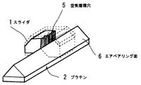
各図に示すように、リニアモータは、スライダ1及びプラテン2から主に構成され、そのスライダ1の頂部にはスライダ部材の外側部分を冷却するための空気循環通路を形成するガイド7を設けた構造となっている。
【0021】
プラテン2の、スライダ1に面する上面(以下、「エアベアリング面6」という)は、互いに直角に隣り合う2面により山型に形成されている。スライダ1は、エアベアリング面6を挟みこむようなV字型スライダとして構成されている。スライダ1をこのようなV字型スライダとして構成することにより、スライダ1のプラテン2に対する移動は、図1に示す矢印Aの方向に制限される。なお、スライダ1は、その内部にあるバイアスマグネット(不図示)により、プラテン2に磁気的に吸引されている。
【0022】
スライダ1は、1組のスライダ部材1a及び1bを組み合わせて構成されている。各スライダ部材1a及び1bの内部には、エアチューブ(不図示)からの空気の供給を受ける空気供給孔8とモータコア(不図示)が設けられている。空気供給孔8にエアチューブから空気が供給されると、その空気は図3に示すようにスライダ1とプラテン2のエアベアリング面6との間に供給され、エアベアリングを構成する空気流通路6aが形成される。このようにスライダ1とプラテン2との間にエアベアリングが形成された場合、空気の圧力とバイアスマグネットの吸引力とが釣り合うことにより、スライダ1は、高剛性で、プラテン2上を摩擦なしで動くことが可能となる。
【0023】
スライダ部材1aとスライダ部材1bとの間、すなわちスライダ1のV字の一番深い部分には、プラテン2のエアベアリング面6に接する部分からスライダ1のエアベアリングと反対の面に向かってスライダ1を貫通するように、空気循環穴5が設けられている。なお、図1及び図2に示した例では空気循環穴5が3つ設けられているが、空気循環穴5の数はこれに限られるものではないことは、いうまでもない。
【0024】
スライダ1の上方には、スライダ1の上面を覆うようにガイド7が設けられている。ガイド7の形状は、スライダ1の上面の形状に対応する。ガイド7は、後述するように、空気循環穴5から流出する空気の流れる方向を規制する空気循環通路9を形成する。
【0025】
なお、図3には、スライダ1及びプラテン2をスライダ1の空気循環穴5の位置で、図1の矢印Aの方向に垂直な断面でカットした状態が示されている。
【0026】
上記構成において、エアチューブから供給された空気は、空気供給孔8を介してエアベアリング面6とスライダ1との間へ供給される。供給された空気は、エアベアリング面6を流れた後、第1の空気流出部10からモータ外部に流出する。また、供給された空気の一部は、エアベアリング面6を流れた後、空気循環穴5を通ってスライダ1の上面へ流出するが、空気循環穴5の上方にはガイド7が設けられているために空気はスライダ1の上面に沿って、すなわち空気循環通路9を通って流れ、第2の空気流出部11から流出する。
【0027】
このように、空気供給孔8からエアベアリング面6に供給される空気の一部は、空気循環穴5及び空気循環通路9を通り、スライダ部材1a及び1bの周囲を循環して第2の空気流出部11から外部に流れることになる。供給される空気は常温であり、この空気が各スライダ部材1a及び1bを囲むように流れるので、スライダ部材1a及び1bから発生した熱を奪い、これによりスライダ部材1a及び1bを冷却する冷却媒体として機能する。
【0028】
以上説明したように、本実施形態によれば、エアベアリングを構成するために供給される空気を冷却媒体として利用し、その空気がスライダ部材1a及び1bの周りを流れるように空気循環穴5及び空気循環通路9を形成したので、付加的な冷却装置を用いることなくスライダ部材1a及び1bを冷却することが可能となる。
なお、本実施形態ではリニアモータの例を示したが、これに限らず回転型のモータ、スライダが2次元方向に移動するモータ(2次元モータ)等であってもよい。
【0029】
また、リニアパルスモータの発熱によるスライダ1やプラテン2の熱膨張を抑制することができるため、モータの機械的精度を保持することが可能となる。
【0030】
更に、モータの発熱による取りつけワークへの影響をできるだけ小さく抑制することも可能となる。
【発明の効果】
【0031】
以上説明したように、本発明によれば、モータのエアベアリングのために供給されていた空気をモータの周囲に流すことができるので、特別な装置を設けることなくモータの冷却することが可能となるという効果が得られる。
【図面の簡単な説明】
【図1】本発明の一実施形態に係るリニアモータの概略構成を示す外観斜視図である。
【図2】図1に示したリニアモータを構成するスライダの断面を示す部分断面図である。
【図3】図1に示したリニアモータの断面図である。
【図4】従来のアブソリュートリニアモータの概略構成を示す外観斜視図である。
【符号の説明】
1 スライダ
1a,1b スライダ部材
2 プラテン
5 空気循環穴
6 エアベアリング面
6a 空気流通路
7 ガイド
8 空気供給孔
9 空気供給通路
10 第1の空気流出部
11 第2の空気流出部[0001]
BACKGROUND OF THE INVENTION
The present invention relates to a motor using an air bearing as a bearing and a method for cooling such a motor.
[0002]
[Prior art]
A conventionally used absolute linear motor will be described with reference to FIG.
[0003]
FIG. 4 is an external perspective view showing a schematic configuration of a conventional absolute linear motor. In the figure, a
[0004]
In the above configuration, air is supplied between the
[0005]
In the linear motor as described above, an electromagnet is formed by winding a copper wire around an iron core. Then, by controlling the current flowing through the copper wire, a force attracting each other is generated between the electromagnet and the iron portion on the
[0006]
By the way, when a current is passed through the copper wire, heat is generated by the resistance of the copper wire. In addition, eddy currents are generated in the iron core, which also generates heat. Further, when a motor driving circuit or the like is incorporated on the
[0007]
[Problems to be solved by the invention]
As described above, heat is generated when the linear motor is driven by passing an electric current. If the heat generation is large, the
[0008]
The present invention has been made in view of the above problems, and an object of the present invention is to provide a motor and a motor cooling method capable of cooling the motor without providing a special device.
[0009]
[Means for Solving the Problems]
In order to achieve the above object, the motor according to the present invention can be configured as follows.
[0010]
(1) A movable slider, a platen for restricting the moving direction of the slider, an air supply means for supplying air into the slider, and provided between the slider and the platen, from the air supply means In a motor having an air flow passage that forms an air bearing by flowing supplied air, one of air flowing through the air flow passage from the air flow passage through the slider toward the upper surface of the slider. And a guide that covers an upper surface of the slider and regulates a direction in which the air flowing through the air circulation hole flows out.
[0011]
(2) The motor according to (1), wherein the slider is configured by combining two slider members, and the air circulation hole is provided between the two slider members.
[0012]
(3) The motor according to (1), wherein the guide covers an upper surface of the slider and forms an air circulation passage through which the air flowing through the air circulation hole flows along the slider.
[0013]
(4) The motor according to (1), wherein at least two of the air circulation holes are provided in the slider.
[0014]
(5) A movable slider, a platen for regulating the moving direction of the slider, an air supply means for supplying air into the slider, and provided between the slider and the platen, from the air supply means In a cooling method for a motor having an air flow passage that forms an air bearing by flowing supplied air, the air flow passage extends from the air flow passage through the slider toward the upper surface of the slider. A method for cooling a motor, wherein a part of the flowing air is flown and a direction in which the part of the air flows out is regulated around the slider on an upper surface of the slider .
[0015]
(6) The motor according to (5), wherein the slider is configured by combining two slider members, and a part of the air flowing through the air flow passage is caused to flow between the two slider members. Cooling method.
[0016]
(7) The motor cooling method according to (5), characterized in that an air circulation passage is formed in which air that has flowed from the air flow passage to the upper surface of the slider flows along the slider.
[0017]
With this configuration, the air supplied for the air bearing of the linear motor can flow around the motor, so that the motor can be cooled without providing a special device.
[0018]
DETAILED DESCRIPTION OF THE INVENTION
Hereinafter, an embodiment of a motor and a motor cooling method of the present invention will be described with reference to FIGS.
[0019]
1 is an external perspective view showing a schematic configuration of a motor according to the present embodiment, FIG. 2 is a partial cross-sectional view showing a cross section of a slider constituting the motor shown in FIG. 1, and FIG. It is sectional drawing of the shown motor. These figures show examples of linear motors.
[0020]
As shown in each figure, the linear motor is mainly composed of a
[0021]
An upper surface (hereinafter referred to as “air bearing
[0022]
The
[0023]
Between the
[0024]
A guide 7 is provided above the
[0025]
3 shows a state in which the
[0026]
In the above configuration, the air supplied from the air tube is supplied between the
[0027]
In this way, a part of the air supplied from the
[0028]
As described above, according to the present embodiment, the air supplied to form the air bearing is used as a cooling medium, and the air circulation hole 5 and the air flow so that the air flows around the
In the present embodiment, an example of a linear motor has been described.
[0029]
Further, since the thermal expansion of the
[0030]
Furthermore, it is possible to suppress the influence of the heat generated by the motor on the work to be mounted as small as possible.
【The invention's effect】
[0031]
As described above, according to the present invention, since the air supplied for the motor air bearing can be flowed around the motor, the motor can be cooled without providing a special device. The effect of becoming is obtained.
[Brief description of the drawings]
FIG. 1 is an external perspective view showing a schematic configuration of a linear motor according to an embodiment of the present invention.
2 is a partial cross-sectional view showing a cross section of a slider constituting the linear motor shown in FIG. 1. FIG.
3 is a cross-sectional view of the linear motor shown in FIG.
FIG. 4 is an external perspective view showing a schematic configuration of a conventional absolute linear motor.
[Explanation of symbols]
DESCRIPTION OF
Claims (7)
前記空気流通路から前記スライダを貫通して前記スライダの上面へ向かい、前記空気流通路を流れる空気の一部が流される空気循環穴と、
前記スライダの上面を覆い、前記空気循環穴を流れた空気が流出する方向を規制するガイドと
を設けたことを特徴とするモータ。A movable slider, a platen for regulating the moving direction of the slider, an air supply means for supplying air into the slider, and provided between the slider and the platen, and supplied from the air supply means In a motor having an air flow passage that forms an air bearing by flowing air,
An air circulation hole through which a part of the air flowing through the air flow passage flows from the air flow passage to the upper surface of the slider through the slider;
A motor that covers an upper surface of the slider and regulates a direction in which the air flowing through the air circulation hole flows out.
前記空気流通路から前記スライダを貫通して前記スライダの上面へ向かって、前記空気流通路を流れる空気の一部を流し、
前記スライダの上面において、前記空気の一部が流出する方向を前記スライダの周囲に規制することを特徴とするモータの冷却方法。A movable slider, a platen for regulating the moving direction of the slider, an air supply means for supplying air into the slider, and provided between the slider and the platen, and supplied from the air supply means In a method for cooling a motor having an air flow passage that forms an air bearing by flowing air,
A portion of the air flowing through the air flow passage is passed from the air flow passage through the slider toward the upper surface of the slider;
A method for cooling a motor, wherein a direction in which a part of the air flows out is regulated around the slider on an upper surface of the slider .
Priority Applications (1)
| Application Number | Priority Date | Filing Date | Title |
|---|---|---|---|
| JP2001194296A JP4200414B2 (en) | 2001-06-27 | 2001-06-27 | Motor and motor cooling method |
Applications Claiming Priority (1)
| Application Number | Priority Date | Filing Date | Title |
|---|---|---|---|
| JP2001194296A JP4200414B2 (en) | 2001-06-27 | 2001-06-27 | Motor and motor cooling method |
Publications (2)
| Publication Number | Publication Date |
|---|---|
| JP2003018817A JP2003018817A (en) | 2003-01-17 |
| JP4200414B2 true JP4200414B2 (en) | 2008-12-24 |
Family
ID=19032456
Family Applications (1)
| Application Number | Title | Priority Date | Filing Date |
|---|---|---|---|
| JP2001194296A Expired - Fee Related JP4200414B2 (en) | 2001-06-27 | 2001-06-27 | Motor and motor cooling method |
Country Status (1)
| Country | Link |
|---|---|
| JP (1) | JP4200414B2 (en) |
Families Citing this family (2)
| Publication number | Priority date | Publication date | Assignee | Title |
|---|---|---|---|---|
| JP5091454B2 (en) * | 2006-10-23 | 2012-12-05 | 株式会社東芝 | Shaft motor and control system thereof |
| CN110719011B (en) * | 2019-11-01 | 2021-04-13 | 东莞市智赢智能装备有限公司 | Bilateral air-floatation linear motor |
-
2001
- 2001-06-27 JP JP2001194296A patent/JP4200414B2/en not_active Expired - Fee Related
Also Published As
| Publication number | Publication date |
|---|---|
| JP2003018817A (en) | 2003-01-17 |
Similar Documents
| Publication | Publication Date | Title |
|---|---|---|
| US6469406B1 (en) | Cooling apparatus for a linear motor | |
| US6300691B1 (en) | Linear motor with an improved cooling structure | |
| JP3870413B2 (en) | Coreless linear motor | |
| JP3532814B2 (en) | XY gantry cooling system | |
| JP5135898B2 (en) | Linear actuator | |
| JPH09154272A (en) | Cooling structure of linear motor | |
| JP4517278B2 (en) | Coreless linear motor and canned linear motor | |
| JP4200414B2 (en) | Motor and motor cooling method | |
| US20020047314A1 (en) | Linear motor with coil assemblies molded in synthetic resin | |
| JP5135984B2 (en) | Linear motor | |
| JP4415567B2 (en) | Linear motor armature and linear motor using the same | |
| CN111279596B (en) | Linear motor with armature cooling channel | |
| JP3878939B2 (en) | Air-cooled coil unit of linear motor | |
| JP4594093B2 (en) | Drive device | |
| JP3661978B2 (en) | Moving coil linear motor | |
| JP2004064874A (en) | High acceleration type linear motor | |
| KR20020081891A (en) | Linear motor with cooling device | |
| JP2003230264A (en) | Linear motor | |
| JP5029830B2 (en) | Linear motor and table feeding device having the same | |
| KR100339914B1 (en) | Cooling System of Linear Motor | |
| JP4092550B2 (en) | Voice coil linear motor with cooling function | |
| JP2001251841A (en) | Linear actuator | |
| JP2002247831A (en) | Linear motor | |
| JP3830479B2 (en) | Linear stepping motor | |
| KR100351970B1 (en) | Cooling System for Linear Motor |
Legal Events
| Date | Code | Title | Description |
|---|---|---|---|
| A621 | Written request for application examination |
Free format text: JAPANESE INTERMEDIATE CODE: A621 Effective date: 20051109 |
|
| A521 | Written amendment |
Free format text: JAPANESE INTERMEDIATE CODE: A523 Effective date: 20051115 |
|
| A977 | Report on retrieval |
Free format text: JAPANESE INTERMEDIATE CODE: A971007 Effective date: 20080704 |
|
| A131 | Notification of reasons for refusal |
Free format text: JAPANESE INTERMEDIATE CODE: A131 Effective date: 20080724 |
|
| A521 | Written amendment |
Free format text: JAPANESE INTERMEDIATE CODE: A523 Effective date: 20080729 |
|
| TRDD | Decision of grant or rejection written | ||
| A01 | Written decision to grant a patent or to grant a registration (utility model) |
Free format text: JAPANESE INTERMEDIATE CODE: A01 Effective date: 20080911 |
|
| A01 | Written decision to grant a patent or to grant a registration (utility model) |
Free format text: JAPANESE INTERMEDIATE CODE: A01 |
|
| A61 | First payment of annual fees (during grant procedure) |
Free format text: JAPANESE INTERMEDIATE CODE: A61 Effective date: 20080924 |
|
| R150 | Certificate of patent or registration of utility model |
Free format text: JAPANESE INTERMEDIATE CODE: R150 |
|
| FPAY | Renewal fee payment (event date is renewal date of database) |
Free format text: PAYMENT UNTIL: 20111017 Year of fee payment: 3 |
|
| LAPS | Cancellation because of no payment of annual fees |