JP3661978B2 - Moving coil linear motor - Google Patents
Moving coil linear motor Download PDFInfo
- Publication number
- JP3661978B2 JP3661978B2 JP04731199A JP4731199A JP3661978B2 JP 3661978 B2 JP3661978 B2 JP 3661978B2 JP 04731199 A JP04731199 A JP 04731199A JP 4731199 A JP4731199 A JP 4731199A JP 3661978 B2 JP3661978 B2 JP 3661978B2
- Authority
- JP
- Japan
- Prior art keywords
- linear motor
- coil
- permanent magnet
- passage
- moving coil
- Prior art date
- Legal status (The legal status is an assumption and is not a legal conclusion. Google has not performed a legal analysis and makes no representation as to the accuracy of the status listed.)
- Expired - Lifetime
Links
Images


Description
【0001】
【発明の属する技術分野】
本発明は、対向するヨーク間に形成された磁気空間内を可動子コイルが直線移動する形式のリニアモータに関し、可動子コイルの最大電流値の維持および永久磁石の熱減磁抑制により、最大推力を向上させ得る可動コイル形リニアモータに関するものである。
【0002】
【従来の技術】
従来、数10〜100cmといった長いストロークの範囲内で物体の位置決めを行うための駆動装置としては、例えば、特公昭58−49100号や実開昭63−93783号公報によって開示されているような可動コイル形リニアモータが使用されている。この可動コイル形リニアモータについて図6を参照して説明する。先ず、1はヨークであり鉄板のような強磁性材料により、例えばU字あるいは平板を組立てて門形に形成したものである。2は永久磁石で厚さ方向に着磁し表面にNS磁極が交互に出現するようにヨーク1の長手方向に配設固着し、さらに左右ヨーク1の内側対向面にも磁気空間3を介して永久磁石2の異極同士が対向するように配設されている。4は支持板で前記ヨーク1と同様の強磁性材料からなり前記磁気空間3を確保するためにヨーク1の長手方向両端部に固着したものである。
【0003】
次ぎに、5はコイルとホルダ等を一体に備えた可動子であり前記磁気空間3における磁束と巻線方向が直交するような扁平の多相コイルによって形成している。これは例えば3相コイルを永久磁石2の配設方向に若干量ずらして並べ、磁極の方向を磁界検出素子(MRセンサ)等の手段を介して検出するようになし、単相または3相の正弦波電流を通電して駆動とその方向を切り替えるように構成されている。尚、可動子には図中点線で示すテーブル6等が取り付けられることになり、これの直線移動を利用することになる。
【0004】
以上の構成により、コイル5に電流を流すとコイル5の巻線方向が永久磁石2による磁束と直交しているので、コイル5はフレミングの左手の法則により、ヨーク1の長手方向の駆動力を得ることになり、コイル5を一体に支持している可動子はヨーク1の長手方向に移動する。次にコイル5に前記と逆方向の電流を流すと、コイル5には前記と逆方向の駆動力が作用するから可動子は前記と逆方向に移動する。従って、コイル5への通電とその方向を選択し、且つその位置をMRセンサで検知することにより可動子を所定位置に移動制御させることが出来る。
【0005】
この可動コイル形リニアモータによれば、磁気回路部にセンターヨークがなく、しかも磁気空間内で磁束が複数個の閉ループを構成し、磁路の一部に磁束が集中しないようになっているので、長いストロークの全域に亘って一様な磁束密度を発生させることが出来る。さらに可動子の質量が小さく、コギングトルクも小さいことから速応性の良好なリニアモータになるという特徴を有している。
【0006】
しかしながら、その反面狭い磁気空間3内にコイル5が配置されているため自然対流による熱交換や熱放散の効率が悪く、しかも発熱源であるコイル5が可動子側に存在するため冷却手段が採りにくいという構造上の問題がある。さらに、コイル5の発熱によりコイル自体の電気抵抗値が上昇しジュール熱損失が増大することから実効電力が減少する。このためコイル5に対する供給電力は、コイル発熱が実用上問題とならない程度の値以下に制限して使用されている。また一方で、対向する永久磁石2にもコイル5からの熱が伝達されて永久磁石2の温度が上昇し熱減磁により発生磁束が減少する。以上のことから発生推力が減少するという性能上の問題がある。
【0007】
そこで、コイルを冷却することが望まれる、例えば実開平4−34878号によれば固定ヨークの側面部に複数個の軸流ファンを設けてコイルを冷却することが提案されている。
【0008】
【発明が解決しようとする課題】
しかしながら、上記した実開平4−34878号の冷却手段では、軸流ファンを設けることによってリニアモータの大型化と構造の複雑化を招来する結果となる。通常、可動磁石形リニアモータの場合はコイル側は動かないので、これを冷却する手段は水冷または空冷でも比較的効率良く実施可能であるが、可動コイル形リニアモータの場合はコイル側が動くことから効率的な冷却構造をとることは困難であった。従って、可動コイル形リニアモータにあっては冷却手段を備えていないのが実状である。
【0009】
そこで本発明は、コイルの空冷構造を安価で簡易なものとすると共に効率的な効果が得られるような空冷手段を備えた可動コイル形リニアモータを提供することを目的とする。
【0010】
【課題を解決するための手段】
本発明は、ヨークの長手方向に複数個の永久磁石を交互に磁極が異なるように配設し、磁石の表面に沿って形成された磁気空間内にコイルを備えた可動子を前記永久磁石の配設方向に移動可能に設けるようにした可動コイル形リニアモータにおいて、前記永久磁石はヨークの長手方向に所定間隙をあけて配設し、この所定間隙の間に通路を設け、この通路の前記コイルまたは永久磁石に対応する部位に通気穴を設け、前記通路にエアーを供給することによってエアーを磁気空間内に吹き付け、前記コイルを冷却するようにした可動コイル形リニアモータである。
【0011】
上記可動コイル形リニアモータにおいて、その通路としては、永久磁石間の所定間隙に折り返し蛇行状に配設したもの。永久磁石の所定間隙の間と上下に繋がった梯子状に配設したもの。永久磁石の所定間隙の間と上または下に繋がったT字状に配設したもの等がある。
また、上記永久磁石間の所定間隙をLg、交番磁界周期をLmとしたとき、LgはLm/3〜Lm/8とし、Lm/4以下とすることが望ましい。また通気穴は適宜複数個設けることができる。
【0012】
本発明の可動コイル形リニアモータは、駆動距離が比較的長尺のリニアモータに適してる。すなわち、コイルまたは永久磁石を冷却するエアー供給通路をエアー配管状に構成したので長尺のヨークであっても容易に配置できヨーク長さに制約を受けない。また、隣り合う永久磁石間に所定の間隙を設けたことによって、磁束分布を正弦波化することができ、その制御性が向上する。さらに、エアー配管がこれらの間隙の間を蛇行状や梯子状またはT字状に這わせ易く、冷却エアーは磁気空間内に流入し可動コイルは効果的に冷却される。よって、コイル側の熱損失と磁石側の熱減磁を共に減少させてリニアモータの高推力を達成しまた保持できる。尚、隣り合う永久磁石間の所定間隙Lgは、対向する永久磁石間における磁束量を有効に発生させるために交番磁界周期Lmに対しLm/3〜Lm/8の範囲内となしLm/4を目処に設定している。交番磁界の周期が16〜100mmとすれば実用範囲では4〜25mm程度が選択され得るが、リニアモータの占有面積や経済性の点から特に8〜15mm程度が好ましい。
【0013】
【発明の実施の形態】
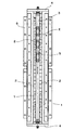
以下、本発明の一実施例を図面を参照して説明する。図1はリニアモータの要部の斜視図、図2はリニアモータ全体の上面図、図3は図2のA−A断面図である。図4は本発明の他の実施例を示す斜視図である。図5は本発明の更に他の実施例を示す斜視図である。尚、これらの図は構造の概略を示す簡略図であり実際の構造は示していない。また、従来と同様の構成については同一符号を付してその説明は省略する。
【0014】
図1〜図3において、ヨーク7は軟鋼のような強磁性材料の平板を左右に対向配置し、同じく平板状の下部ヨーク73とから構成されており、対向するヨーク間で磁石の表面に沿って磁気空間3を構成している。尚、下部ヨーク73は一体ものでもまた別体を組み立てたものでも良い。そして、左右ヨーク7の長手方向の磁石配設面71には永久磁石、例えばNd―Fe―B系異方性焼結磁石2をその極性が交互に異なるように隣り合って配設固着し、尚かつ対向する磁石同士の極性が異なるように配設固着している。磁気空間3内には上述の従来技術と同様多相コイルからなる可動子5が装置されており、この多相コイルに駆動回路(図示せず)からの正弦波駆動電流を供給して直線移動(紙面上下方向)させるようにした可動コイル形リニアモータである。尚、永久磁石2と可動子5との間隔は図のように大きなイメージではなく実際は0.02〜2mm程度の隙間を保って設けられている。また、永久磁石や可動子の実施態様は上記に限るものではない。
【0015】
本実施例では、磁石配設面71には永久磁石2の交番磁界がより完全な正弦波に近づくように隣同士の間隙Lgを8〜15mm内で選択し、永久磁石2を直接固着している。そして、この間隙の間にエアー通路となる金属管(銅、ステンレス等)あるいは樹脂管、ゴム管等からなるエアー配管70が永久磁石2の間を這うように蛇行状に設けられている。そしてエアー配管70には永久磁石2や可動子コイル5に相当する部位に通気穴75が複数個、ここでは3個設けられており、この通気穴75がエアー供給口となっている。エアー配管の一端から装置の空圧駆動源やエアコンプレッサ等によって冷却用エアーを供給すると、永久磁石2及び可動子5に冷却エアーを吹き付けてこれらを直接冷却することができる。
よって、コイルの発熱と永久磁石の温度上昇を共に抑えることができるので、大電流を流すことも可能となりリニアモータの高推力化を達成できる。
【0016】
図4は他の実施例を示す斜視図である。本例では図示の通り通路を梯子状のエアー配管としたものである。エアー配管80にも永久磁石2や可動子コイル5に相当する部位に通気穴85が複数個設けてある。尚、通気孔は上下の配管に設けても良い。そして、この配管に冷却用エアーを供給すると、永久磁石2及び可動子5に冷却エアーを吹き付けてこれらを直接冷却することができる。
【0017】
図5はさらに他の実施例を示す斜視図である。本例では図示の通り通路をT字状のエアー配管としたものである。エアー配管90にも永久磁石2や可動子コイル5に相当する部位に通気穴95が複数個設けてある。そして同様に、この配管に冷却用エアーを供給すると、永久磁石2及び可動子5に冷却エアーを吹き付けてこれらを直接冷却することができる。
【0018】
また、上記実施例はいずれも対向するヨークのそれぞれに永久磁石を設け、磁気空間を介して異極が対向するように配設固着した可動コイル形リニアモータを例にとったが、磁気回路はこれに限ることなく片側のヨークのみに永久磁石を配設したものでもよい。このような場合はコイルの巻き方、ヨーク形状、永久磁石の磁力や形状について考慮することによって同様の可動コイル形リニアモータを機能させることができるので、このリニアモータの構造に上記した実施例を適用することもできる。
【0019】
【発明の効果】
以上説明したように本発明は、可動コイル形リニアモータにおいて、エアー配管を永久磁石の所定間隙の間に蛇行状に這わせ、通気穴より冷却用エアーを供給してコイル及び永久磁石を冷却したものである。これによって磁束分布が正弦波化されて制御性が向上し、かつ冷却用エアーによって可動コイルを直接冷却すると共に永久磁石の温度上昇を抑えることが出来る。
よって、コイル側の熱損失と磁石側の熱減磁を共に減少させてリニアモータに供給する電流に制限を加えることなく高推力を出すことができる。またリニアモータの適用範囲の拡大が可能となる。
【図面の簡単な説明】
【図1】本発明の実施例を示すリニアモータの要部斜視図である。
【図2】本発明の実施例を示すリニアモータの上面図である。
【図3】図2のA−A矢視図である。
【図4】本発明の他の実施例を示すリニアモータの要部斜視図である。
【図5】本発明の更に他の実施例を示すリニアモータの要部斜視図である。
【図6】従来の可動コイル形リニアモータの一例を示す上面図である。
【符号の説明】
1:ヨーク、2:永久磁石、3:磁気空間、4:支持板、5:可動子
6:テーブル等、 7、8、9、10:ヨーク
70、80、90:冷却エアー配管
71、81、91:磁石配設面
75、85、95:通気穴[0001]
BACKGROUND OF THE INVENTION
The present invention relates to a linear motor in which a mover coil linearly moves in a magnetic space formed between opposing yokes. The maximum thrust is achieved by maintaining the maximum current value of the mover coil and suppressing thermal demagnetization of a permanent magnet. The present invention relates to a moving coil linear motor that can improve the above.
[0002]
[Prior art]
Conventionally, as a driving device for positioning an object within a long stroke range of several 10 to 100 cm, for example, a movable device as disclosed in Japanese Patent Publication No. 58-49100 and Japanese Utility Model Publication No. 63-93783 is disclosed. A coiled linear motor is used. This moving coil linear motor will be described with reference to FIG. First,
[0003]
Next,
[0004]
With the above configuration, when a current is passed through the
[0005]
According to this moving coil type linear motor, there is no center yoke in the magnetic circuit section, and the magnetic flux forms a plurality of closed loops in the magnetic space so that the magnetic flux is not concentrated on a part of the magnetic path. A uniform magnetic flux density can be generated over the entire long stroke. Furthermore, since the mass of the mover is small and the cogging torque is also small, the linear motor has a good speed response.
[0006]
However, since the
[0007]
Therefore, for example, Japanese Utility Model Laid-Open No. 4-34878 proposes cooling a coil by providing a plurality of axial fans on the side surface of the fixed yoke.
[0008]
[Problems to be solved by the invention]
However, the cooling means disclosed in Japanese Utility Model Laid-Open No. 4-34878 results in an increase in the size and complexity of the linear motor by providing an axial fan. Normally, in the case of a movable magnet type linear motor, the coil side does not move, so the means for cooling it can be implemented relatively efficiently even with water cooling or air cooling, but in the case of a moving coil type linear motor, the coil side moves. It was difficult to have an efficient cooling structure. Therefore, the actual condition is that the moving coil linear motor is not provided with a cooling means.
[0009]
SUMMARY OF THE INVENTION An object of the present invention is to provide a movable coil linear motor having an air cooling means that can make an air cooling structure of a coil inexpensive and simple and can obtain an efficient effect.
[0010]
[Means for Solving the Problems]
In the present invention, a plurality of permanent magnets are alternately arranged in the longitudinal direction of the yoke so that the magnetic poles are different from each other, and a mover having a coil in a magnetic space formed along the surface of the magnet is provided. In the movable coil type linear motor arranged to be movable in the arrangement direction, the permanent magnet is arranged with a predetermined gap in the longitudinal direction of the yoke, and a passage is provided between the predetermined gaps. The movable coil linear motor is provided with a vent hole in a portion corresponding to a coil or a permanent magnet, and air is blown into the magnetic space by supplying air to the passage to cool the coil.
[0011]
In the moving coil type linear motor, the passage is arranged in a meandering manner in a predetermined gap between permanent magnets. A ladder that is connected between a predetermined gap between the permanent magnets and above and below. There are those arranged in a T-shape that is connected between a predetermined gap of a permanent magnet and above or below.
Further, when the predetermined gap between the permanent magnets is Lg and the alternating magnetic field period is Lm, Lg is set to Lm / 3 to Lm / 8, and preferably Lm / 4 or less. A plurality of ventilation holes can be provided as appropriate.
[0012]
The moving coil linear motor of the present invention is suitable for a linear motor having a relatively long driving distance. That is, since the air supply passage for cooling the coil or the permanent magnet is configured in the form of an air pipe, even a long yoke can be easily arranged and the yoke length is not limited. Further, by providing a predetermined gap between adjacent permanent magnets, the magnetic flux distribution can be made sinusoidal, and the controllability is improved. In addition, the air pipe can be easily formed in a meandering shape, a ladder shape, or a T shape between the gaps, and the cooling air flows into the magnetic space, thereby effectively cooling the movable coil. Therefore, both the heat loss on the coil side and the thermal demagnetization on the magnet side can be reduced to achieve and maintain the high thrust of the linear motor. The predetermined gap Lg between the adjacent permanent magnets has a value Lm / 4 within the range of Lm / 3 to Lm / 8 with respect to the alternating magnetic field period Lm in order to effectively generate the amount of magnetic flux between the opposing permanent magnets. The target is set. If the period of the alternating magnetic field is 16 to 100 mm, about 4 to 25 mm can be selected in the practical range, but about 8 to 15 mm is particularly preferable from the viewpoint of the occupation area and economical efficiency of the linear motor.
[0013]
DETAILED DESCRIPTION OF THE INVENTION
Hereinafter, an embodiment of the present invention will be described with reference to the drawings. 1 is a perspective view of the main part of the linear motor, FIG. 2 is a top view of the entire linear motor, and FIG. 3 is a cross-sectional view taken along the line AA of FIG. FIG. 4 is a perspective view showing another embodiment of the present invention. FIG. 5 is a perspective view showing still another embodiment of the present invention. These drawings are simplified views showing the outline of the structure, and the actual structure is not shown. In addition, the same components as those in the prior art are denoted by the same reference numerals and description thereof is omitted.
[0014]
1 to 3, a
[0015]
In the present embodiment, the gap Lg between the adjacent magnets is selected within 8 to 15 mm so that the alternating magnetic field of the
Therefore, since both the heat generation of the coil and the temperature rise of the permanent magnet can be suppressed, it is possible to flow a large current and to achieve high thrust of the linear motor.
[0016]
FIG. 4 is a perspective view showing another embodiment. In this example, the passage is a ladder-like air pipe as shown. The
[0017]
FIG. 5 is a perspective view showing still another embodiment. In this example, as shown in the figure, the passage is a T-shaped air pipe. The
[0018]
In the above embodiments, each of the opposing yokes is provided with a permanent magnet, and a moving coil type linear motor is arranged and fixed so that different poles face each other through a magnetic space. The present invention is not limited to this, and a permanent magnet may be provided only on one yoke. In such a case, the same moving coil type linear motor can be made to function by considering the coil winding method, the yoke shape, and the magnetic force and shape of the permanent magnet. It can also be applied.
[0019]
【The invention's effect】
As described above, according to the present invention, in the movable coil type linear motor, the air pipe is meandered between the predetermined gaps of the permanent magnets, and cooling air is supplied from the ventilation holes to cool the coils and the permanent magnets. Is. As a result, the magnetic flux distribution is converted into a sine wave, the controllability is improved, the moving coil is directly cooled by the cooling air, and the temperature rise of the permanent magnet can be suppressed.
Therefore, it is possible to reduce the heat loss on the coil side and the thermal demagnetization on the magnet side, and to produce a high thrust without limiting the current supplied to the linear motor. In addition, the application range of the linear motor can be expanded.
[Brief description of the drawings]
FIG. 1 is a perspective view of an essential part of a linear motor showing an embodiment of the present invention.
FIG. 2 is a top view of a linear motor showing an embodiment of the present invention.
FIG. 3 is a view taken along arrow AA in FIG. 2;
FIG. 4 is a perspective view of an essential part of a linear motor showing another embodiment of the present invention.
FIG. 5 is a perspective view of an essential part of a linear motor showing still another embodiment of the present invention.
FIG. 6 is a top view showing an example of a conventional moving coil linear motor.
[Explanation of symbols]
1: yoke, 2: permanent magnet, 3: magnetic space, 4: support plate, 5: mover 6: table, etc. 7, 8, 9, 10:
Claims (5)
Priority Applications (1)
| Application Number | Priority Date | Filing Date | Title |
|---|---|---|---|
| JP04731199A JP3661978B2 (en) | 1999-02-25 | 1999-02-25 | Moving coil linear motor |
Applications Claiming Priority (1)
| Application Number | Priority Date | Filing Date | Title |
|---|---|---|---|
| JP04731199A JP3661978B2 (en) | 1999-02-25 | 1999-02-25 | Moving coil linear motor |
Publications (2)
| Publication Number | Publication Date |
|---|---|
| JP2000245131A JP2000245131A (en) | 2000-09-08 |
| JP3661978B2 true JP3661978B2 (en) | 2005-06-22 |
Family
ID=12771759
Family Applications (1)
| Application Number | Title | Priority Date | Filing Date |
|---|---|---|---|
| JP04731199A Expired - Lifetime JP3661978B2 (en) | 1999-02-25 | 1999-02-25 | Moving coil linear motor |
Country Status (1)
| Country | Link |
|---|---|
| JP (1) | JP3661978B2 (en) |
Families Citing this family (5)
| Publication number | Priority date | Publication date | Assignee | Title |
|---|---|---|---|---|
| JP4496710B2 (en) * | 2003-03-27 | 2010-07-07 | 日産自動車株式会社 | Cooling structure of rotating electric machine |
| US7696652B2 (en) * | 2005-11-01 | 2010-04-13 | Asml Netherlands B.V. | Electromagnetic actuator, method of manufacturing a part of an electromagnetic actuator, and lithographic apparatus comprising and electromagnetic actuator |
| TWI489742B (en) * | 2012-10-11 | 2015-06-21 | Hiwin Mikrosystem Corp | Linear motor air-cooling structure |
| KR101308317B1 (en) * | 2013-03-19 | 2013-10-04 | 장석호 | Electric motor which serves as power generator also using coil plate having devided coil and reciprocating sliding plate having devided magnet |
| DE102020122239A1 (en) | 2020-08-25 | 2022-03-03 | Intrasys Gmbh Innovative Transportsysteme | Linear motor stator assembly with external forced convective cooling |
-
1999
- 1999-02-25 JP JP04731199A patent/JP3661978B2/en not_active Expired - Lifetime
Also Published As
| Publication number | Publication date |
|---|---|
| JP2000245131A (en) | 2000-09-08 |
Similar Documents
| Publication | Publication Date | Title |
|---|---|---|
| JP5292707B2 (en) | Moving magnet type linear motor | |
| JP3870413B2 (en) | Coreless linear motor | |
| KR100844759B1 (en) | Coreless linear motor | |
| US6469406B1 (en) | Cooling apparatus for a linear motor | |
| JP5072064B2 (en) | Cylindrical linear motor | |
| JP2002051530A (en) | Linear motor | |
| JPH09154272A (en) | Cooling structure of linear motor | |
| JP2000253640A (en) | Linear vibration motor | |
| JP2001218444A (en) | High thrust linear motor and method of manufacturing the same | |
| JP3661978B2 (en) | Moving coil linear motor | |
| JP2003309963A (en) | Cooling apparatus for linear slider | |
| WO2013105214A1 (en) | Linear motor | |
| JP3878939B2 (en) | Air-cooled coil unit of linear motor | |
| JP3835946B2 (en) | Moving coil linear motor | |
| JPH10323012A (en) | Linear motor | |
| JP2000228860A (en) | Cooler for linear motor | |
| JP2008220020A (en) | Movable magnet type linear motor | |
| JPH11243677A (en) | Coaxial linear motor | |
| JP2010148233A (en) | Linear motor driving and feeding device | |
| JP3838314B2 (en) | Moving coil linear motor | |
| JP2002247831A (en) | Linear motor | |
| JP2524103Y2 (en) | Synchronous linear motor | |
| JP7115185B2 (en) | Moving coil type voice coil motor | |
| JP3446563B2 (en) | Linear motor | |
| JPH08317627A (en) | Linear motor |
Legal Events
| Date | Code | Title | Description |
|---|---|---|---|
| A711 | Notification of change in applicant |
Free format text: JAPANESE INTERMEDIATE CODE: A712 Effective date: 20040525 |
|
| A977 | Report on retrieval |
Free format text: JAPANESE INTERMEDIATE CODE: A971007 Effective date: 20050217 |
|
| TRDD | Decision of grant or rejection written | ||
| A01 | Written decision to grant a patent or to grant a registration (utility model) |
Free format text: JAPANESE INTERMEDIATE CODE: A01 Effective date: 20050316 |
|
| A61 | First payment of annual fees (during grant procedure) |
Free format text: JAPANESE INTERMEDIATE CODE: A61 Effective date: 20050318 |
|
| R150 | Certificate of patent or registration of utility model |
Free format text: JAPANESE INTERMEDIATE CODE: R150 |
|
| S111 | Request for change of ownership or part of ownership |
Free format text: JAPANESE INTERMEDIATE CODE: R313115 |
|
| FPAY | Renewal fee payment (event date is renewal date of database) |
Free format text: PAYMENT UNTIL: 20080401 Year of fee payment: 3 |
|
| R350 | Written notification of registration of transfer |
Free format text: JAPANESE INTERMEDIATE CODE: R350 |
|
| FPAY | Renewal fee payment (event date is renewal date of database) |
Free format text: PAYMENT UNTIL: 20090401 Year of fee payment: 4 |
|
| FPAY | Renewal fee payment (event date is renewal date of database) |
Free format text: PAYMENT UNTIL: 20100401 Year of fee payment: 5 |
|
| FPAY | Renewal fee payment (event date is renewal date of database) |
Free format text: PAYMENT UNTIL: 20110401 Year of fee payment: 6 |
|
| FPAY | Renewal fee payment (event date is renewal date of database) |
Free format text: PAYMENT UNTIL: 20120401 Year of fee payment: 7 |
|
| FPAY | Renewal fee payment (event date is renewal date of database) |
Free format text: PAYMENT UNTIL: 20130401 Year of fee payment: 8 |
|
| FPAY | Renewal fee payment (event date is renewal date of database) |
Free format text: PAYMENT UNTIL: 20130401 Year of fee payment: 8 |
|
| FPAY | Renewal fee payment (event date is renewal date of database) |
Free format text: PAYMENT UNTIL: 20140401 Year of fee payment: 9 |
|
| EXPY | Cancellation because of completion of term |