JP4199928B2 - Barrel with plastic lid - Google Patents
Barrel with plastic lid Download PDFInfo
- Publication number
- JP4199928B2 JP4199928B2 JP2000550747A JP2000550747A JP4199928B2 JP 4199928 B2 JP4199928 B2 JP 4199928B2 JP 2000550747 A JP2000550747 A JP 2000550747A JP 2000550747 A JP2000550747 A JP 2000550747A JP 4199928 B2 JP4199928 B2 JP 4199928B2
- Authority
- JP
- Japan
- Prior art keywords
- lid
- barrel
- ring
- web
- edge
- Prior art date
- Legal status (The legal status is an assumption and is not a legal conclusion. Google has not performed a legal analysis and makes no representation as to the accuracy of the status listed.)
- Expired - Lifetime
Links
Images


Classifications
-
- B—PERFORMING OPERATIONS; TRANSPORTING
- B65—CONVEYING; PACKING; STORING; HANDLING THIN OR FILAMENTARY MATERIAL
- B65D—CONTAINERS FOR STORAGE OR TRANSPORT OF ARTICLES OR MATERIALS, e.g. BAGS, BARRELS, BOTTLES, BOXES, CANS, CARTONS, CRATES, DRUMS, JARS, TANKS, HOPPERS, FORWARDING CONTAINERS; ACCESSORIES, CLOSURES, OR FITTINGS THEREFOR; PACKAGING ELEMENTS; PACKAGES
- B65D47/00—Closures with filling and discharging, or with discharging, devices
- B65D47/04—Closures with discharging devices other than pumps
- B65D47/06—Closures with discharging devices other than pumps with pouring spouts or tubes; with discharge nozzles or passages
- B65D47/12—Closures with discharging devices other than pumps with pouring spouts or tubes; with discharge nozzles or passages having removable closures
- B65D47/121—Stoppers
-
- B—PERFORMING OPERATIONS; TRANSPORTING
- B65—CONVEYING; PACKING; STORING; HANDLING THIN OR FILAMENTARY MATERIAL
- B65D—CONTAINERS FOR STORAGE OR TRANSPORT OF ARTICLES OR MATERIALS, e.g. BAGS, BARRELS, BOTTLES, BOXES, CANS, CARTONS, CRATES, DRUMS, JARS, TANKS, HOPPERS, FORWARDING CONTAINERS; ACCESSORIES, CLOSURES, OR FITTINGS THEREFOR; PACKAGING ELEMENTS; PACKAGES
- B65D43/00—Lids or covers for rigid or semi-rigid containers
- B65D43/02—Removable lids or covers
- B65D43/0202—Removable lids or covers without integral tamper element
- B65D43/0214—Removable lids or covers without integral tamper element secured only by friction or gravity
- B65D43/0218—Removable lids or covers without integral tamper element secured only by friction or gravity on both the inside and the outside of the mouth of the container
-
- B—PERFORMING OPERATIONS; TRANSPORTING
- B65—CONVEYING; PACKING; STORING; HANDLING THIN OR FILAMENTARY MATERIAL
- B65D—CONTAINERS FOR STORAGE OR TRANSPORT OF ARTICLES OR MATERIALS, e.g. BAGS, BARRELS, BOTTLES, BOXES, CANS, CARTONS, CRATES, DRUMS, JARS, TANKS, HOPPERS, FORWARDING CONTAINERS; ACCESSORIES, CLOSURES, OR FITTINGS THEREFOR; PACKAGING ELEMENTS; PACKAGES
- B65D45/00—Clamping or other pressure-applying devices for securing or retaining closure members
- B65D45/32—Clamping or other pressure-applying devices for securing or retaining closure members for applying radial or radial and axial pressure, e.g. contractible bands encircling closure member
-
- B—PERFORMING OPERATIONS; TRANSPORTING
- B65—CONVEYING; PACKING; STORING; HANDLING THIN OR FILAMENTARY MATERIAL
- B65D—CONTAINERS FOR STORAGE OR TRANSPORT OF ARTICLES OR MATERIALS, e.g. BAGS, BARRELS, BOTTLES, BOXES, CANS, CARTONS, CRATES, DRUMS, JARS, TANKS, HOPPERS, FORWARDING CONTAINERS; ACCESSORIES, CLOSURES, OR FITTINGS THEREFOR; PACKAGING ELEMENTS; PACKAGES
- B65D2543/00—Lids or covers essentially for box-like containers
- B65D2543/00009—Details of lids or covers for rigid or semi-rigid containers
- B65D2543/00018—Overall construction of the lid
- B65D2543/00064—Shape of the outer periphery
- B65D2543/00074—Shape of the outer periphery curved
- B65D2543/00092—Shape of the outer periphery curved circular
-
- B—PERFORMING OPERATIONS; TRANSPORTING
- B65—CONVEYING; PACKING; STORING; HANDLING THIN OR FILAMENTARY MATERIAL
- B65D—CONTAINERS FOR STORAGE OR TRANSPORT OF ARTICLES OR MATERIALS, e.g. BAGS, BARRELS, BOTTLES, BOXES, CANS, CARTONS, CRATES, DRUMS, JARS, TANKS, HOPPERS, FORWARDING CONTAINERS; ACCESSORIES, CLOSURES, OR FITTINGS THEREFOR; PACKAGING ELEMENTS; PACKAGES
- B65D2543/00—Lids or covers essentially for box-like containers
- B65D2543/00009—Details of lids or covers for rigid or semi-rigid containers
- B65D2543/00018—Overall construction of the lid
- B65D2543/00259—Materials used
- B65D2543/00296—Plastic
-
- B—PERFORMING OPERATIONS; TRANSPORTING
- B65—CONVEYING; PACKING; STORING; HANDLING THIN OR FILAMENTARY MATERIAL
- B65D—CONTAINERS FOR STORAGE OR TRANSPORT OF ARTICLES OR MATERIALS, e.g. BAGS, BARRELS, BOTTLES, BOXES, CANS, CARTONS, CRATES, DRUMS, JARS, TANKS, HOPPERS, FORWARDING CONTAINERS; ACCESSORIES, CLOSURES, OR FITTINGS THEREFOR; PACKAGING ELEMENTS; PACKAGES
- B65D2543/00—Lids or covers essentially for box-like containers
- B65D2543/00009—Details of lids or covers for rigid or semi-rigid containers
- B65D2543/00444—Contact between the container and the lid
- B65D2543/00481—Contact between the container and the lid on the inside or the outside of the container
- B65D2543/0049—Contact between the container and the lid on the inside or the outside of the container on the inside, or a part turned to the inside of the mouth of the container
- B65D2543/005—Contact between the container and the lid on the inside or the outside of the container on the inside, or a part turned to the inside of the mouth of the container both cup and skirt
-
- B—PERFORMING OPERATIONS; TRANSPORTING
- B65—CONVEYING; PACKING; STORING; HANDLING THIN OR FILAMENTARY MATERIAL
- B65D—CONTAINERS FOR STORAGE OR TRANSPORT OF ARTICLES OR MATERIALS, e.g. BAGS, BARRELS, BOTTLES, BOXES, CANS, CARTONS, CRATES, DRUMS, JARS, TANKS, HOPPERS, FORWARDING CONTAINERS; ACCESSORIES, CLOSURES, OR FITTINGS THEREFOR; PACKAGING ELEMENTS; PACKAGES
- B65D2543/00—Lids or covers essentially for box-like containers
- B65D2543/00009—Details of lids or covers for rigid or semi-rigid containers
- B65D2543/00444—Contact between the container and the lid
- B65D2543/00481—Contact between the container and the lid on the inside or the outside of the container
- B65D2543/0049—Contact between the container and the lid on the inside or the outside of the container on the inside, or a part turned to the inside of the mouth of the container
- B65D2543/00509—Cup
-
- B—PERFORMING OPERATIONS; TRANSPORTING
- B65—CONVEYING; PACKING; STORING; HANDLING THIN OR FILAMENTARY MATERIAL
- B65D—CONTAINERS FOR STORAGE OR TRANSPORT OF ARTICLES OR MATERIALS, e.g. BAGS, BARRELS, BOTTLES, BOXES, CANS, CARTONS, CRATES, DRUMS, JARS, TANKS, HOPPERS, FORWARDING CONTAINERS; ACCESSORIES, CLOSURES, OR FITTINGS THEREFOR; PACKAGING ELEMENTS; PACKAGES
- B65D2543/00—Lids or covers essentially for box-like containers
- B65D2543/00009—Details of lids or covers for rigid or semi-rigid containers
- B65D2543/00444—Contact between the container and the lid
- B65D2543/00481—Contact between the container and the lid on the inside or the outside of the container
- B65D2543/00537—Contact between the container and the lid on the inside or the outside of the container on the outside, or a part turned to the outside of the mouth of the container
-
- B—PERFORMING OPERATIONS; TRANSPORTING
- B65—CONVEYING; PACKING; STORING; HANDLING THIN OR FILAMENTARY MATERIAL
- B65D—CONTAINERS FOR STORAGE OR TRANSPORT OF ARTICLES OR MATERIALS, e.g. BAGS, BARRELS, BOTTLES, BOXES, CANS, CARTONS, CRATES, DRUMS, JARS, TANKS, HOPPERS, FORWARDING CONTAINERS; ACCESSORIES, CLOSURES, OR FITTINGS THEREFOR; PACKAGING ELEMENTS; PACKAGES
- B65D2543/00—Lids or covers essentially for box-like containers
- B65D2543/00009—Details of lids or covers for rigid or semi-rigid containers
- B65D2543/00444—Contact between the container and the lid
- B65D2543/00481—Contact between the container and the lid on the inside or the outside of the container
- B65D2543/00555—Contact between the container and the lid on the inside or the outside of the container on both the inside and the outside
-
- B—PERFORMING OPERATIONS; TRANSPORTING
- B65—CONVEYING; PACKING; STORING; HANDLING THIN OR FILAMENTARY MATERIAL
- B65D—CONTAINERS FOR STORAGE OR TRANSPORT OF ARTICLES OR MATERIALS, e.g. BAGS, BARRELS, BOTTLES, BOXES, CANS, CARTONS, CRATES, DRUMS, JARS, TANKS, HOPPERS, FORWARDING CONTAINERS; ACCESSORIES, CLOSURES, OR FITTINGS THEREFOR; PACKAGING ELEMENTS; PACKAGES
- B65D2543/00—Lids or covers essentially for box-like containers
- B65D2543/00009—Details of lids or covers for rigid or semi-rigid containers
- B65D2543/00953—Sealing means
- B65D2543/00962—Sealing means inserted
- B65D2543/00972—Collars or rings
-
- B—PERFORMING OPERATIONS; TRANSPORTING
- B65—CONVEYING; PACKING; STORING; HANDLING THIN OR FILAMENTARY MATERIAL
- B65D—CONTAINERS FOR STORAGE OR TRANSPORT OF ARTICLES OR MATERIALS, e.g. BAGS, BARRELS, BOTTLES, BOXES, CANS, CARTONS, CRATES, DRUMS, JARS, TANKS, HOPPERS, FORWARDING CONTAINERS; ACCESSORIES, CLOSURES, OR FITTINGS THEREFOR; PACKAGING ELEMENTS; PACKAGES
- B65D2543/00—Lids or covers essentially for box-like containers
- B65D2543/00009—Details of lids or covers for rigid or semi-rigid containers
- B65D2543/00953—Sealing means
- B65D2543/0099—Integral supplemental sealing lips
Abstract
Description
【0001】
本発明は請求項の上位概念として記載した形式の、樽本体と、その上に載置された、内部に挿入されたシールを備えた樽蓋と、緊締リング錠とを有するプラスチック蓋付き樽に関する。このような蓋付き樽は例えば特許明細書US5427264号により公知である。
【0002】
従来技術:
従来の構造のプラスチック蓋付き樽においては、樽蓋のシールは垂直な蓋外側ウエブと垂直な蓋内リングとにより(図2参照)保持されていた。落下試験(=樽転倒)又は内圧試験では、中央の蓋円板が上方へ膨らみ、その結果、垂直な蓋内リングが垂直な状態から内方と上方へ変形し、これによってシールリングにかかる負荷が除かれ、樽開口縁に対するシール座を失い、極端な領域では漏れが生じることになる。
【0003】
発明の課題:
本発明の課題は樽蓋と樽開口縁との間の強められた結合により、改善されたシール特性が、特に内圧が高い場合もしくは樽転倒の場合(波動圧が発生した場合)でも達成されるようにすることである。
【0004】
発明の解決手段:
本発明による蓋付き樽においては、樽蓋はU字形の蓋縁内部に別の回転対称的に環状に延びるシールウエブを有し、シールが外側のリング形の蓋ウエブとシールウエブとの間に配置されているのに対し、シールウエブと内側のリング形の蓋ウエブとの間に、下に向かって開いたリング形の空室が形成されており、シールウエブと内側の蓋ウエブとが互いに間隔をおいて配置され、上方の結合部だけで互いに結合されている。この有利な処置により、公知技術の欠点をはっきりと改善する樽蓋において、垂直な蓋内リングが内方と上方へ著しく変形した場合にも、引続き垂直に維持されるシールウエブによりシールにかかる負荷が除かれることがなくなる。むしろシールは、内側でシールに境界を接する垂直なウエブによって基本的に軸方向及び半径方向により良好に保持され、蓋付き樽が外部から負荷された場合にもシール領域での変形が減少することにより、樽開口縁を樽蓋に対し確実にシールすることになる。
【0005】
他の変化解決策によれば、蓋下面に、蓋縁の内側のリング形の蓋ウエブに続いて、周方向に環状に延びかつ−横断面方向で見て−閉じた補強部材が配置されている。この補強部材は内部中空に又は発泡させられて構成されている。中空であるか又は発泡させられた補強部材は加熱されたプラスチックを射出成形型に圧入する間のガスインジェクション技術によって構成することができる。他の形式で補強部材はあらかじめ製作された、別個のリング形のプラスチック部分を溶かすことにより、内部中空し、しかし閉鎖されて構成されることもできる。ねじれ強い補強部材が樽蓋の外側領域に配置され、該補強部材が樽開口に侵入しかつ内側で樽開口に支えられることにより、適当な形式で、蓋が変形される際の蓋シールの負荷が許容される程度を越えて除かれかつそのシール作用を失うことが阻止される。本発明による構成では、上方の樽開口縁が内側に、環状に延びるシール条材に加えてかつこのシール条材からわずかな間隔をおいて、垂直に起立する成形リングを備えている。この成形リングは樽蓋が載置された場合に錠止状態で、シールウエブと内側のリング形の蓋ウエブとの間のリング形の空間内に係合する。したがってこれにより、蓋内リングが大きく変形した場合ですら、付加的な垂直なシールウエブが内方もしくは上方へ変形する危険はなくなる。何故ならば樽蓋の付加的な垂直なシールウエブは上方の樽本体縁における付加的な垂直な成形リングにより背後から掴まれかつ固持されるからである。載置された、緊締リングで錠止された樽蓋の錠止状態では、起立した成形リングと下へ向いたシールウエブは少なくとも5mmオーバラップする。起立した成形リングは単にセグメント状に、つまり中断されて構成されるか又は環状の成形リングとして構成されていることができる。この場合、環状の成形リングは根元領域を通って延びる少なくとも1つの孔を、場合によってはその内部にある液体を流出させるために備えている。
【0006】
有利な実施例ではシールウエブと内側のリング形の蓋ウエブとの間の空間に別の環状の蓋シールが挿入されている。この蓋シールは樽蓋の錠止状態で、起立した環状に延びる成形リングの上縁に対し、樽開口縁/樽蓋縁の結合を付加的にシールする。これによって外部負荷に際してさらに改善されたシール作用が達成される。
【0007】
本発明による蓋付き樽は以下の重要な特徴と利点とを有している。
【0008】
(イ) 樽本体における付加的な垂直な成形リングはそれによって形成された溝を脱水できるために部分的に中断されている。
【0009】
(ロ) 樽本体における付加的な垂直な成形リングが付加的な垂直な蓋ウエブのより良好な保持のために延長されて構成されている。
【0010】
(ハ) 樽本体における付加的な垂直な成形リングが樽蓋におけるシールと関連して樽蓋/樽開口縁の領域を付加的にシールする。
【0011】
(ニ) U字形の蓋縁の内側に対する内側の蓋円板の結合が、平らな溝底を有する、上方に開いた、ほぼU字形の係合溝を介して行われる。この場合、内側の蓋円板もしくは蓋円板の少なくとも中央領域の高さ位置は、上方の蓋縁の高さ平面と同一平面にあるか又はこれを上方に越えるように構成されている。
【0012】
実施例:
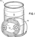
図1には符号10で樽本体12と樽蓋14と緊締リング16とを有する蓋付き樽が示されている。樽蓋14は高分子の熱可塑性プラスチック(HDPE)から成り、射出成形方法で製作されている。樽体12は同様に高分子の熱可塑性プラスチック(HDPE)から成り、射出成形方法で、しかし有利にはブロー成形方法で製作されている。緊締リング16は銅板又はプラスチックから成っている。蓋縁と樽本体縁とは本発明による特別な特徴で構成されている。
【0013】
図2には既に公知である蓋付き樽構造の樽蓋14に、上昇した内圧が及ぼした変形作用が示されている。この蓋付き樽では樽本体12は上方の中実に据え込まれた、肉厚に構成された樽開口縁18に環状のシール条材24を有し、樽蓋14は下に向けられたU字形の蓋縁29を備えている。蓋縁20は外側のリング形の蓋ウエブ26と内側のリング形の蓋ウエブ28とを備えている。この場合、両方の蓋ウエブ26,28との間にはシール22が挿入(発泡又は埋設)されている。緊締リング錠16はほぼ台形である、内方へ開いた横断面を有し、錠止状態で、上方の脚30によりU字形の蓋縁20を上方から掴み、下方の脚32により上方の樽開口縁18の近隣領域にてほぼ半径方向外方へ突出する周面フランジ34を下から掴んでいる。緊締リング16の錠止状態では蓋シール22はそのシール作用を発揮するために上方の樽開口縁18のシール条材24に対し圧着させられている。内圧作用により樽蓋14の中央の蓋円板42は強く、軸方向で見て外方へ膨らまされている。これにより蓋縁20の内側の蓋ウエブ28は−矢印で示したように−内方へ引っ張られかつ上方へ持ち上げられているかもしくは押し離されている。この結果、蓋シール22にかかる負荷は内側で次第に弱められ、蓋シール22は内方へ逃げることができるようになり、そのシール作用は低減することになる。まったく似たような形式で、樽が転倒した場合にも、樽開口縁の折曲作用がもっとも大きい樽蓋領域においてシール作用の減退が見られる。前記の不都合なシール作用の減退の回避は図3に示された本発明の実施例で実現される。この場合には下方へU字形に開いた蓋縁20の外側の蓋ウエブ26と内側の蓋ウエブ28との間に、付加的な軸方向に下方に向いたシールウエブ36が構成されている。蓋シール22は外側のシールウエブ26と付加的なシールウエブ36との間に配置されかつ固定されている。この場合、シールウエブ36は狭いギャップを形成してもしくはほぼ2〜4mmのわずかな間隔を内側の蓋ウエブ28からおいて構成されており、比較的に薄い上方の結合部40だけを介して内側の蓋ウエブ28と弾性的に曲げ結合されている。下方にて、平らな又は外方へ湾曲させられた内側の蓋円板42が、内側の蓋ウエブ28の下縁に接続している。U字形の蓋縁20の内側に対する内側の蓋円板42の結合部は、外側の蓋ウエブ26の下方の縁の高さに又は−図4により示したように−それよりも低く位置するように構成されていることができる。蓋円板42の下面にはさらに2つの、軸方向で下方に延びる内リング部分64,66(図5参照)又は閉じられた中空リング形のプラスチック部分56が補強部材54として設けられていることができる。
【0014】
別の実施例は図4において、樽蓋14とこれに属する緊締リング16と樽本体12のシングル構造の樽開口縁18とを示している。この場合には樽蓋は係合溝44と上方へ持上げられた内側の蓋円板42を備えている。係合溝44は樽掴み工具の上方の爪が係合するために少なくとも15mmの深さと、半径方向の寸法(幅)が少なくとも10mmである平らな溝底46とを備えている。溝底46の内側に接続して、ほぼ軸方向又は斜めに円錐形に延びるリング片70が結合部材として、直径の縮小された中央の蓋円板42に向かって上向きに延びている。内側の蓋円板42の高さ位置もしくは蓋円板42の少なくとも膨らまされた中央領域は−図示のように−上方の蓋縁20の高さ平面と同一平面を成して又は上方に向かってこれを越えて構成されていることができる(図10)。
【0015】
補強されて構成された樽開口縁を有する有利な実施例は図5に示されている。この場合には上方の樽開口縁18は内側に環状のシール条材24に加えてかつこれから間隔をおいて垂直に起立した成形リング48を有している。この成形リング48は樽蓋が載置された場合に、錠止状態で、シールウエブ36と内側のリング形の蓋ウエブ28との間のリング形の空間38内へ係合する。この場合、起立した成形リング48とシールウエブ36との間では上方の樽開口縁18の内側に環状の保持溝52が構成されている。この保持溝52には樽蓋のシールウエブ36が係合する。十分な相互支持を達成するためには、起立した成形リング48とシールウエブ36とが、樽蓋14が載置されかつ緊締リング16で止められた錠止状態で−軸方向で見て−少なくとも5mmオーバラップさせられている。この実施例では上方の蓋縁20にて内側の蓋ウエブ28を空間38の上側で蓋ウエブ26と結合する結合部40はフレキシブルに弾性的に例えば凹入成形(ヒンジの形式)で構成されている。起立した成形リング48はこの場合には成形リング48の根元領域を通って延びる少なくとも1つの孔50を備えた環状の成形リング48として構成されている。したがって場合によっては保持溝内に達する液状の充填物は再び内側へ向かって樽本体内へ流出することができる。
【0016】
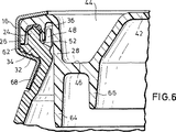
図6に示された変化実施例においては、起立した成形リング48はセグメント状に、つまり中断されて構成され、したがって保持溝52内に液状の充填物が溜まらないようになっている。この場合には緊締リング16の下方の脚32のための支持面も、周面フランジ34がほぼ3mm外方へ突出するフランジ縁延長部62を備えていることで幅が広げられている。内側のリング形の蓋ウエブ28は中央の蓋円板42もしくは係合溝44の溝底46を越えて下方へ延長されて軸方向外側の内リング部分64として構成されている。さらに樽蓋の下面には軸方向外側の内リング部分64に対し少なくとも10mmの半径方向の間隔をおいて第2の内リング部分66が構成されている。この場合には−載置された樽蓋で示したように−軸方向外側の内リング部分64は第2の内リング部分66よりも少なくとも5mmだけ長く内側へ向かって樽本体内へ突入するように構成されていることができる。有利な構成では、外側の樽開口縁の補強のために緊締リング16は、その下方の脚部32に接続した、ほぼ軸方向に延びる、外側の樽壁に接触させられる延長エプロン68を有している。有利な形式でこの延長エプロン68は外側の樽壁における凹所に係合し、樽を掴む樽グリッパもしくはその下側の樽掴み爪が上へ動く場合もしくは樽を掴む場合に、延長エプロンの、後退させられた、外側の樽壁と同一面を成して延びる下縁に引っ掛からないようになっている。さらにこの図には本発明の重要な特徴、つまり蓋付き樽に積重ね負荷が作用した場合に、例えばこのような樽を錠止状態で3つ互いに重ねた場合に、外側の蓋ウエブ26がフランジ縁延長部62に支えられかつシールウエブ36が保持溝52の溝底に支持されることが示されている。この場合には軸方向で見てシール条材24の上側には少なくとも2mmのギャップが蓋シール22のために残っており、したがって過剰負荷が作用した場合にも蓋シール22の持続的な不備は発生しない。
【0017】
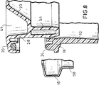
図7に示された本発明の実施例では蓋下面に周方向に延びる、蓋縁20の内側のリング形の蓋ウエブ28に接続した−横断面で見て−閉じられた補強部材54が配置されている。この補強部材54は内部が中空に構成されている。この、中空ではあるが、しかしねじれ強い補強部材54は、公知のガスインジェクション技術を射出成形過程の間に使用して製作することができる。
【0018】
図8の実施例は閉じられて発泡成形された補強部材54を示している。発泡成形された補強部材54は射出成形型もしくは補強部材のための中空型室内に発泡材をノズル噴射することで生ぜしめることができる。
【0019】
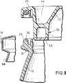
さらに図9には、補強部材54が、あらかじめ製作された別個のリング状のプラスチック部分を溶かして中空に、しかし閉じられて構成される変化実施例が示されている(図3も参照)。この実施例ではシール条材24は上部に起立した小さな環状突起70を備えている。この環状突起70は蓋シール22内に押し込まれ、蓋シール22が付加的に側方へ滑り動くことを防止する。
【0020】
図10には、内側の蓋円板42の内部に少なくとも1つの側方の閉鎖栓60が2−ツオル(約50.8mm)又は3−ツオル(約76.2mm)閉鎖栓として配置されている。同じ形式で適当な大きさの中央閉鎖栓が内側の蓋円板42内に配置されていることもできる。本発明による樽蓋は300mmよりも大きい比較的に大きな直径を有している。樽容量が35USガロン(約132.5l)であるほぼ円筒形の蓋付き樽の場合には樽高さ約860mmで、より大きな蓋直径約472mmを有するのに対し、55USガロン(約208l)の樽容量を有する蓋付き樽(図1参照)の場合には樽高さ約898mmで蓋直径は約576mmである。これらの樽は従来使用されている蓋付き樽よりも約15%大きい樽開口を有している。より小さい剛性の大きい蓋(200mmよりも小さい)又はねじキャップの場合には内圧で蓋が前述の如く膨らむという問題はさほど発生しない。前記蓋形状では両方の内リング部分64,66はその根元領域にそれぞれ少なくとも1つの孔72を備えている。これにより蓋付き樽を液状の充填物で、例えば閉鎖栓60を通して完全に充填すると、空気が内リング部分の後ろに逃げることができる。同様にこの孔72は軽く傾けられた、頭を下にした残留量放出位置で内リング部分64,66の後ろにある残留液が流出することを許す。
【0021】
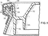
図11による有利な実施例ではシールウエブ36と内側のリング形の蓋ウエブ28との間の空間38には、別の第2の環状の蓋シール58が挿入されている。この蓋シール58は樽蓋14の錠止状態で、起立する環状の成形リング48の上方縁に対し、樽開口縁/樽蓋縁の結合を付加的にシールする。このダブルシールは特に例えば樽が転倒した場合の波動圧力負荷に対し適している。
【0022】
図12aに概略的に示された、床衝突(=周面落下)の時点の最大変形を伴う樽においては衝突軸線に沿った断面線I−Iが示されている。樽蓋縁と樽本体縁との相互の負荷は図12bによる部分断面図で示されている。衝突エネルギで蓋14はその内側の蓋ウエブ28で蓋開口縁18の内壁を押し、シールウエブ36は樽開口縁のシール条材24に対して側方へ押される。この場合には中央の蓋円板42が強く外へ膨らんでいるにも拘わらず、この個所においては蓋付き樽のシール性を損なうシール負荷の除去の危険は発生しない。この危険はむしろ図13aで概略的に示した、床衝突(=周面落下)の時点の最大変形を伴う樽において衝突軸線に対し約45°を成す断面線II−IIの領域にて発生する。樽蓋縁と樽本体縁とのこの問題となる個所での相互負荷のリアクションは図13bの部分断面図で説明する。樽本体12は半径方向で樽蓋14のようには剛性が大きくない。樽本体12は樽開口縁18の領域で特に強く外へ変形し、樽開口縁/樽蓋縁結合を付加的に負荷する。樽蓋14は同じ形式で一緒に膨らむことができず、特に係合溝44と中央の蓋円板42の結合個所の領域にてきわめて平らに変形させられる。これまでは蓋シール22の負荷が内側から除かれ樽蓋縁が緊締リング16の下へ引出される惧れがあった。これは本発明による蓋構造では発生しない。何故ならば外側の蓋ウエブ28は側方でシール条材24によって上方の樽開口縁18にかつ蓋側のシールウエブ36は側方で成形リング48によって形状接続で固持されるからである。したがって蓋縁は2重に相互に支持され、蓋シール座もしくは蓋シール22の周囲の近隣領域はその相互位置を変化させないので、有利な形式で一杯のシール作用が損なわれることなく維持される。
【0023】
もちろん前記実施例に示された特徴は有意義な形式で互いに組合わすことができることは言うまでもない。
【図面の簡単な説明】
【図1】 本発明による蓋付き樽(Vanguard FRH-樽II)の斜視図。
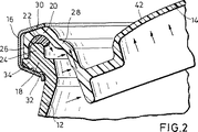
【図2】 公知の蓋付き樽の樽蓋縁と樽本体開口との結合領域の部分断面図。
【図3】 本発明の樽蓋の拡大部分断面図。
【図4】 他の樽蓋縁を樽本体開口と緊締リングと共に示した図。
【図5】 樽蓋縁と樽本体開口と緊締リングとの別の実施例を示した図。
【図6】 樽蓋縁と樽本体開口と緊締リングとの別の実施例を示した図。
【図7】 樽蓋縁と樽本体開口と緊締リングとの別の実施例を示した図。
【図8】 樽蓋縁と樽本体開口と緊締リングとの別の実施例を示した図。
【図9】 樽蓋縁と樽本体開口と緊締リングとの別の実施例を示した図。
【図10】 樽蓋縁と樽本体開口と緊締リングとの別の実施例を示した図。
【図11】 樽蓋縁と樽本体開口と緊締リングとの別の実施例を示した図。
【図12a】 床衝突時点での変形を伴う樽の概略図。
【図12b】 図12aの樽蓋縁/樽本体開口の結合領域の衝突軸I−Iに沿った断面図。
【図13a】 床衝突(周面落下試験)時点の変形を伴う樽の概略図。
【図13b】 図13aの樽蓋縁/樽本体開口の結合領域の衝突軸に対し約45°の線II−IIに沿った断面図。
【符号の説明】
10 蓋付き樽
12 樽本体
14 樽蓋
16 緊締リング[0001]
The present invention relates to a barrel with a plastic lid having a barrel main body, a barrel lid with a seal inserted therein, and a tightening ring lock, of the type described as the superordinate concept of the claims. . Such a barrel with a lid is known, for example, from patent specification US Pat. No. 5,427,264.
[0002]
Conventional technology :
In a conventional barrel with a plastic lid, the barrel lid seal is held by a vertical outer lid web and a vertical inner ring (see FIG. 2). In the drop test (= barrel overturning) or the internal pressure test, the center lid disk bulges upward, and as a result, the vertical lid inner ring deforms inward and upward from the vertical state, and this causes a load on the seal ring Will be lost, and the seal seat for the barrel opening edge will be lost and leakage will occur in extreme areas.
[0003]
Problems of the invention :
The object of the present invention is achieved by an improved connection between the barrel lid and the barrel opening edge, so that improved sealing properties are achieved, especially when the internal pressure is high or when the barrel falls (when wave pressure occurs). Is to do so.
[0004]
Invention Solution :
In the barrel with lid according to the present invention, the barrel lid has another rotationally symmetrical seal web extending inside the U-shaped lid edge, and the seal is between the outer ring-shaped lid web and the seal web. On the other hand, a ring-shaped cavity opened downward is formed between the seal web and the inner ring-shaped lid web, and the seal web and the inner lid web are mutually connected. They are spaced apart and are connected to each other only at the upper connection. With this advantageous measure, in the barrel lid, which clearly improves the disadvantages of the prior art, the load on the seal by the sealing web which remains vertical even if the vertical lid ring is significantly deformed inward and upward. Will not be removed. Rather, the seal is basically better held axially and radially by a vertical web that bounds the seal on the inside, reducing deformation in the seal area even when the covered barrel is loaded from the outside. Thus, the barrel opening edge is surely sealed against the barrel lid.
[0005]
According to another variant solution, on the underside of the lid, a ring-shaped lid web on the inside of the lid rim is arranged, annularly extending in the circumferential direction and viewed in the cross-sectional direction, and closed with a reinforcing member. Yes. The reinforcing member is configured to be hollow inside or foamed. The hollow or foamed reinforcing member can be constructed by gas injection technology during the press-fitting of heated plastic into the injection mold. In other forms, the reinforcing member can be configured to be hollow inside but closed by melting a prefabricated, separate ring-shaped plastic part. A torsionally strong reinforcing member is arranged in the outer region of the barrel lid, and the reinforcing member penetrates into the barrel opening and is supported by the barrel opening on the inside so that the load on the lid seal when the lid is deformed in an appropriate manner Is removed to an extent that is not permissible and is prevented from losing its sealing action. In the arrangement according to the invention, the upper barrel opening edge is provided on the inside with a forming ring which stands vertically in addition to the annularly extending sealing strip and at a slight distance from the sealing strip. This molded ring engages in a ring-shaped space between the sealing web and the inner ring-shaped lid web in a locked state when the barrel lid is placed. Thus, this eliminates the risk of the additional vertical seal web being deformed inward or upward even when the lid ring is greatly deformed. This is because the additional vertical sealing web of the barrel lid is gripped and pinned from behind by an additional vertical forming ring at the upper barrel body edge. In the locked state of the mounted barrel lid locked with the tightening ring, the standing forming ring and the downwardly facing sealing web overlap at least 5 mm. The standing shaped ring can simply be configured in segments, i.e. interrupted or as an annular shaped ring. In this case, the annular shaped ring is provided with at least one hole extending through the root region, possibly for allowing the liquid therein to flow out.
[0006]
In an advantageous embodiment, another annular lid seal is inserted in the space between the sealing web and the inner ring-shaped lid web. This lid seal, in the locked state of the barrel lid, additionally seals the barrel opening edge / barrel lid edge connection to the upper edge of the standing annularly extending forming ring. This achieves a further improved sealing action under external loads.
[0007]
The covered barrel according to the present invention has the following important features and advantages.
[0008]
(A) The additional vertical forming ring in the barrel body is partially interrupted so that the grooves formed thereby can be dewatered.
[0009]
(B) An additional vertical forming ring in the barrel body is extended for better holding of the additional vertical lid web.
[0010]
(C) An additional vertical forming ring in the barrel body additionally seals the barrel lid / barrel opening edge region in conjunction with the seal in the barrel lid.
[0011]
(D) The inner lid disk is joined to the inside of the U-shaped lid edge via an upwardly open, generally U-shaped engagement groove with a flat groove bottom. In this case, the height position of at least the central region of the inner lid disk or the lid disk is configured to be flush with or exceed the height plane of the upper lid edge.
[0012]
Example :
In FIG. 1, a barrel with a lid having a
[0013]
FIG. 2 shows a deformation action in which a raised internal pressure is exerted on a
[0014]
Another embodiment shows in FIG. 4 a
[0015]
An advantageous embodiment with a reinforced barrel opening edge is shown in FIG. In this case, the upper
[0016]
In the alternative embodiment shown in FIG. 6, the upstanding forming
[0017]
In the embodiment of the invention shown in FIG. 7, a closed reinforcing
[0018]
The embodiment of FIG. 8 shows the reinforcing
[0019]
Further, FIG. 9 shows a modified embodiment in which the reinforcing
[0020]
In FIG. 10, at least one lateral closure plug 60 is disposed within the
[0021]
In the preferred embodiment according to FIG. 11, another second
[0022]
In the barrel with maximum deformation at the time of floor collision (= falling surface), schematically shown in FIG. 12a, a section line II along the collision axis is shown. The mutual load between the barrel lid edge and the barrel body edge is shown in a partial sectional view according to FIG. 12b. With the impact energy, the
[0023]
Of course, it goes without saying that the features shown in the embodiments can be combined with each other in a meaningful manner.
[Brief description of the drawings]
FIG. 1 is a perspective view of a barrel (Vanguard FRH-barrel II) with a lid according to the present invention.
FIG. 2 is a partial cross-sectional view of a coupling region between a barrel lid edge of a known barrel with a lid and a barrel main body opening.
FIG. 3 is an enlarged partial cross-sectional view of the barrel lid of the present invention.
FIG. 4 is a view showing another barrel lid edge together with a barrel main body opening and a tightening ring.
FIG. 5 is a view showing another embodiment of the barrel lid edge, the barrel main body opening, and the tightening ring.
FIG. 6 is a view showing another embodiment of the barrel lid edge, the barrel main body opening, and the tightening ring.
FIG. 7 is a view showing another embodiment of the barrel lid edge, the barrel main body opening, and the tightening ring.
FIG. 8 is a view showing another embodiment of the barrel lid edge, the barrel main body opening, and the tightening ring.
FIG. 9 is a view showing another embodiment of the barrel lid edge, the barrel main body opening, and the tightening ring.
FIG. 10 is a view showing another embodiment of the barrel lid edge, the barrel main body opening, and the tightening ring.
FIG. 11 is a view showing another embodiment of the barrel lid edge, the barrel main body opening, and the tightening ring.
FIG. 12a is a schematic view of a barrel with deformation at the time of a floor collision.
12b is a cross-sectional view along the collision axis II of the coupling region of the barrel lid edge / barrel body opening of FIG. 12a.
FIG. 13a is a schematic view of a barrel with deformation at the time of floor collision (circumferential drop test).
13b is a cross-sectional view along line II-II of about 45 ° with respect to the collision axis of the barrel lid edge / barrel body opening coupling region of FIG. 13a.
[Explanation of symbols]
10 barrel with
Claims (6)
(イ) 樽本体(12)が上方の樽開口縁(18)に、環状のシール条材(24)を有し、
(ロ) 樽蓋(14)が下に向いたU字形の蓋縁(20)と該蓋縁(20)の内側の蓋円板(42)とを有し、該蓋縁(20)が外側のリング形の蓋ウエブ(26)と内側のリング形の蓋ウエブ(28)とを有し、前記蓋縁(20)にシール(22)が挿入されており、
(ハ) 緊締リング錠(16)がほぼ台形である、内方へ開いた横断面を有し、錠止状態で上方の脚(30)により、前記U字形の蓋縁(20)を上方から掴んでおり、下方の脚(32)により、ほぼ水平にもしくは軽く斜め下方へ延びるように上方の樽開口の近隣領域に成形された上方の樽本体縁を下方から掴んでおりかつ前記樽蓋縁(20)に挿入された前記シール(22)を上方の樽開口縁(18)における前記環状のシール条材(24)に圧着しており、
(ニ) 樽蓋(14)がU字型の前記樽蓋縁(20)の内部に回転対称的に環状に延びる別のシールウェブ(36)を有しており、
(ホ) 前記シール(22)が前記外側のリング形の蓋ウェブ(26)と前記別のシールウェブ(36)との間に配置されているのに対し、前記別のシールウェブ(36)と前記内側のリング形の蓋ウェブ(28)との間に、下方に向かって開いたリング状の空室(38)が形式されており、前記別のシールウェブ(36)と前記内側のリング形の蓋ウェブ(28)とが相互に間隔をおいて上方の結合部(40)だけで互いに結合されている形式のものにおいて、前記U字形の蓋縁(20)に対する前記内側の蓋円板(42)の結合部が前記外側の蓋ウェブ(26)の下縁の高さに又は該下縁よりも低く位置して構成されており、前記上方の樽開口縁(18)が内側に、前記環状のシール条材(24)に付加的にかつ該シール条材(24)から間隔をおいて垂直に起立する成形リング(48)を有し、該成形リング(48)が樽蓋(14)を載置した場合に、錠止状態で、前記別のシールウェブ(36)と前記内側のリング形の蓋ウェブ(28)との間の前記リング状の空間(38)内へ係合することを特徴とする、プラスチック製蓋付き樽。 A barrel with a plastic lid having a barrel body (12), a barrel lid (14), and a tightening ring lock (16),
(I) The barrel body (12) has an annular seal strip (24) on the upper barrel opening edge (18),
(B) A barrel lid (14) having a U-shaped lid edge (20) facing downward and a lid disk (42) inside the lid edge (20), the lid edge (20) being outside A ring-shaped lid web (26) and an inner ring-shaped lid web (28), and a seal (22) is inserted into the lid edge (20 ) ,
(C) The tightening ring lock (16) is substantially trapezoidal and has an inwardly open cross section, and the U-shaped lid edge (20) is viewed from above by the upper leg (30) in the locked state. grab and, by legs of the lower side (32), OriKatsu the barrel grab barrel body edge of the upper side that is shaped to close a region of the upper barrel opening to extend to substantially horizontally or gently obliquely downward from the lower The seal (22) inserted into the lid edge (20) is crimped to the annular seal strip ( 24) at the upper barrel opening edge (18);
(D) the barrel lid (14) has another sealing web (36) extending in a rotationally symmetrical ring shape inside the U-shaped barrel lid edge (20);
(E) the seal (22) is disposed between the outer ring-shaped lid web (26) and the another seal web (36), whereas the other seal web (36); A ring-shaped cavity (38) opened downward is formed between the inner ring-shaped lid web (28), and the other sealing web (36) and the inner ring-shaped cavity are formed. Of the inner lid disk (20) with respect to the U-shaped lid edge (20) 42) is configured to be positioned at or below the lower edge of the outer lid web (26), with the upper barrel opening edge (18) on the inside, In addition to the annular seal strip (24) and from the seal strip (24) A molding ring (48) that stands vertically at an interval, and when the molding ring (48) mounts the barrel lid (14), in a locked state, the other sealing web (36) A barrel with a plastic lid, characterized in that it engages in the ring-shaped space (38) between the inner ring-shaped lid web (28).
Applications Claiming Priority (3)
| Application Number | Priority Date | Filing Date | Title |
|---|---|---|---|
| DE29809484 | 1998-05-28 | ||
| DE29809484.3 | 1998-05-28 | ||
| PCT/EP1999/003640 WO1999061323A2 (en) | 1998-05-28 | 1999-05-26 | Barrel with plastic lid |
Publications (3)
| Publication Number | Publication Date |
|---|---|
| JP2002516234A JP2002516234A (en) | 2002-06-04 |
| JP2002516234A5 JP2002516234A5 (en) | 2006-04-27 |
| JP4199928B2 true JP4199928B2 (en) | 2008-12-24 |
Family
ID=8057714
Family Applications (1)
| Application Number | Title | Priority Date | Filing Date |
|---|---|---|---|
| JP2000550747A Expired - Lifetime JP4199928B2 (en) | 1998-05-28 | 1999-05-26 | Barrel with plastic lid |
Country Status (10)
| Country | Link |
|---|---|
| US (1) | US6401957B1 (en) |
| EP (1) | EP1086021B1 (en) |
| JP (1) | JP4199928B2 (en) |
| AT (1) | ATE273177T1 (en) |
| AU (1) | AU4266699A (en) |
| BR (1) | BR9911604B1 (en) |
| CA (1) | CA2333473C (en) |
| DE (2) | DE59910215D1 (en) |
| ES (1) | ES2226419T3 (en) |
| WO (1) | WO1999061323A2 (en) |
Families Citing this family (41)
| Publication number | Priority date | Publication date | Assignee | Title |
|---|---|---|---|---|
| DE10005579A1 (en) * | 2000-02-09 | 2001-08-30 | Streuber Sulo Eisenwerk F | Container with body and lid |
| US20020148846A1 (en) * | 2001-04-12 | 2002-10-17 | Ropak Corporation | Container lid having gasketless liquid seal |
| US6959831B2 (en) * | 2001-07-06 | 2005-11-01 | Greif, Inc. | Gasketless drum |
| US20030098550A1 (en) * | 2001-11-26 | 2003-05-29 | Groh William S. | Battery module gasket |
| JP4021671B2 (en) * | 2002-01-23 | 2007-12-12 | 矢崎総業株式会社 | Waterproof box cover assembly structure |
| US7063212B2 (en) | 2002-09-19 | 2006-06-20 | Bill Thomas Associates, Inc. | Multiple seal storage and transport container |
| US20060021982A1 (en) * | 2004-07-28 | 2006-02-02 | Hekal Ihab M | Container Closure |
| US20060138141A1 (en) * | 2004-12-17 | 2006-06-29 | Stolzman Michael D | Reduced thickness cover |
| ZA200509781B (en) * | 2004-12-22 | 2006-09-27 | Schuetz Gmbh & Co Kgaa | Lid barrel |
| US20060138142A1 (en) * | 2004-12-28 | 2006-06-29 | Michael Stolzman | Double ribbed cover |
| US20060175335A1 (en) * | 2005-02-07 | 2006-08-10 | Easterday Dyke T | Container lid and gasket combination without lid pretreatment or gasket adhesive |
| US8245847B2 (en) * | 2005-07-25 | 2012-08-21 | Warren Brent Davis | Reusable nesting and denesting plastic container |
| US8210391B2 (en) * | 2005-10-14 | 2012-07-03 | Ropak Corporation | Performance oriented pail |
| JP5144908B2 (en) * | 2006-03-06 | 2013-02-13 | 矢崎総業株式会社 | Waterproof case |
| US20110089187A1 (en) * | 2006-08-10 | 2011-04-21 | Capitol Vial Inc. | Shatterproof Container And Cap Assembly |
| US8083094B2 (en) * | 2006-08-10 | 2011-12-27 | Capitol Vial Inc. | Container and cap assembly |
| FR2908393B1 (en) * | 2006-11-14 | 2008-12-05 | Safpac Soc Par Actions Simplif | PERFECTED FREQUENCY |
| US20080220316A1 (en) * | 2007-03-06 | 2008-09-11 | Berkowitz Fred J | End cap seal assembly for a lithium cell |
| US20080251515A1 (en) * | 2007-04-12 | 2008-10-16 | Baughman Gary M | Container and lid combination with a sealing gasket and closing ring |
| US20090152271A1 (en) * | 2007-12-12 | 2009-06-18 | Kuzelka Kenneth J | High pressure drum cover |
| US9340330B2 (en) | 2010-06-24 | 2016-05-17 | S. C. Johnson & Son, Inc. | Storage container lids |
| DE102012006735A1 (en) | 2012-04-02 | 2013-10-02 | Dietmar Przytulla | Thermoplastic lid for liquid-tight plastic containers e.g. inner container of pallet container, has seal portion that is axially connected to outer edge of rotationally symmetrical horizontal seal retaining edge in lid portion |
| DE202012003379U1 (en) | 2012-04-02 | 2012-06-04 | Dietmar Przytulla | Plastic lid |
| WO2013154508A1 (en) * | 2012-04-13 | 2013-10-17 | Barbaros Ceylan | A container with a lid |
| US9611082B2 (en) | 2013-05-13 | 2017-04-04 | Owens-Brockway Glass Container Inc. | Seal ring for foil-sealing a container |
| CN104003058B (en) * | 2014-05-16 | 2017-02-01 | 苏州华源包装股份有限公司 | Polyfoam injection technology of barrel lid structure convenient to use |
| GB2526373B (en) | 2014-05-23 | 2018-05-09 | Sangobeg Ltd | Cap |
| USD769119S1 (en) | 2014-05-29 | 2016-10-18 | Sangobeg Limited | Cover |
| JP6634690B2 (en) * | 2015-03-26 | 2020-01-22 | 凸版印刷株式会社 | Container with lid |
| USD782771S1 (en) | 2015-04-03 | 2017-03-28 | Geo Plastics | Tight head drum |
| US10781415B2 (en) | 2015-05-06 | 2020-09-22 | Innovative Distilling Technologies, Inc. | Device for capping a barrel |
| KR102172527B1 (en) * | 2016-03-04 | 2020-10-30 | 씨에스피 테크놀로지스, 인크. | Container and lid |
| ES2869326T3 (en) | 2016-04-20 | 2021-10-25 | Obrist Closures Switzerland | Closure with alveolar zone and procedure for forming said closure |
| CN106864978B (en) * | 2017-02-27 | 2018-09-25 | 东莞产权交易中心 | A kind of paint tube |
| DE102018101885A1 (en) * | 2018-01-29 | 2019-08-01 | Pirlo Industrial GmbH & Co OG | locking mechanism |
| CN109483230B (en) * | 2018-12-26 | 2024-02-23 | 浙江大自然户外用品股份有限公司 | Flexible water bucket assembly equipment and flexible water bucket assembly method |
| CN109628280B (en) * | 2019-01-31 | 2023-12-15 | 上海千岸创意设计有限公司 | Sustainable ferment bucket of throwing material |
| USD938128S1 (en) | 2020-01-06 | 2021-12-07 | Geo Plastics | Nestable drum |
| USD1001413S1 (en) | 2020-06-30 | 2023-10-10 | Geo Plastics | Nestable drum |
| US11345505B2 (en) | 2020-08-19 | 2022-05-31 | Innovative Distilling Technologies, Inc. | Capped barrel system and methods |
| CN115806116A (en) * | 2023-02-08 | 2023-03-17 | 山东润岩环保科技有限公司 | Storage device convenient to open and close sealing cover for emulsion production |
Family Cites Families (15)
| Publication number | Priority date | Publication date | Assignee | Title |
|---|---|---|---|---|
| DE1761614A1 (en) * | 1968-06-15 | 1970-12-17 | Verpackungswerk Bracht Gmbh & | Liquid-tight transport container |
| US3510023A (en) * | 1968-08-14 | 1970-05-05 | Inland Steel Co | Plastic container and lid therefor |
| NL6918704A (en) * | 1969-12-12 | 1971-06-15 | ||
| BE758265A (en) * | 1970-02-21 | 1971-04-01 | Mauser Kg | BARREL OR DRUM WITH LID |
| US3688942A (en) * | 1970-11-20 | 1972-09-05 | Continental Can Co | Container and closure combination |
| DE3241714A1 (en) * | 1982-11-11 | 1984-05-17 | Hermann 6920 Sinsheim Thomin | Container lid |
| FR2602211B1 (en) * | 1986-07-31 | 1988-09-23 | Vittel Eaux Min | PLASTIC OPERATOR |
| US4709833A (en) * | 1987-02-20 | 1987-12-01 | Essex Environmental Industries, Inc. | Rotationally molded salvage drum and recessed lid |
| US4718571A (en) * | 1987-03-27 | 1988-01-12 | Bordner Paul G | Molded lid assembly with primary and secondary latching features |
| GB2251430A (en) * | 1990-12-04 | 1992-07-08 | Brice Edward Mills | Watertight canister |
| DE4108606C1 (en) * | 1991-03-16 | 1992-09-17 | Schuetz-Werke Gmbh & Co Kg, 5418 Selters, De | |
| DE4236338C2 (en) * | 1992-10-28 | 1999-12-30 | Mauser Werke Gmbh | Drum lid |
| US5881898A (en) * | 1996-01-11 | 1999-03-16 | Sonoco Products Company | Open top drum having ribbed chime |
| GB9604808D0 (en) * | 1996-03-07 | 1996-05-08 | Ind Containers Ltd | Pail and plastic lid |
| US5785201A (en) * | 1996-05-02 | 1998-07-28 | Container Accessories, Inc. | Molded lid with wave configured central portion |
-
1999
- 1999-05-26 DE DE59910215T patent/DE59910215D1/en not_active Expired - Lifetime
- 1999-05-26 JP JP2000550747A patent/JP4199928B2/en not_active Expired - Lifetime
- 1999-05-26 US US09/509,187 patent/US6401957B1/en not_active Expired - Lifetime
- 1999-05-26 WO PCT/EP1999/003640 patent/WO1999061323A2/en active IP Right Grant
- 1999-05-26 DE DE19980934T patent/DE19980934D2/en not_active Expired - Lifetime
- 1999-05-26 AT AT99939772T patent/ATE273177T1/en not_active IP Right Cessation
- 1999-05-26 AU AU42666/99A patent/AU4266699A/en not_active Abandoned
- 1999-05-26 ES ES99939772T patent/ES2226419T3/en not_active Expired - Lifetime
- 1999-05-26 BR BRPI9911604-9A patent/BR9911604B1/en not_active IP Right Cessation
- 1999-05-26 CA CA002333473A patent/CA2333473C/en not_active Expired - Fee Related
- 1999-05-26 EP EP99939772A patent/EP1086021B1/en not_active Expired - Lifetime
Also Published As
| Publication number | Publication date |
|---|---|
| ES2226419T3 (en) | 2005-03-16 |
| DE59910215D1 (en) | 2004-09-16 |
| EP1086021A2 (en) | 2001-03-28 |
| AU4266699A (en) | 1999-12-13 |
| WO1999061323A2 (en) | 1999-12-02 |
| ATE273177T1 (en) | 2004-08-15 |
| BR9911604B1 (en) | 2009-01-13 |
| JP2002516234A (en) | 2002-06-04 |
| CA2333473C (en) | 2008-02-19 |
| EP1086021B1 (en) | 2004-08-11 |
| CA2333473A1 (en) | 1999-12-02 |
| US6401957B1 (en) | 2002-06-11 |
| BR9911604A (en) | 2001-10-02 |
| DE19980934D2 (en) | 2001-06-21 |
| WO1999061323A3 (en) | 2000-02-03 |
Similar Documents
| Publication | Publication Date | Title |
|---|---|---|
| JP4199928B2 (en) | Barrel with plastic lid | |
| EP0055007B1 (en) | A sales container | |
| US8210391B2 (en) | Performance oriented pail | |
| US4079857A (en) | Containers and closures | |
| US4177934A (en) | Container and lid | |
| JP3610068B2 (en) | Barrel with lid | |
| DK143739B (en) | BLAST-CASTED PLASTIC CONTAINER WITH A NECK PART AND A SURFACE LOCATED BELOW | |
| US6834772B1 (en) | Packaging | |
| US4387820A (en) | Closing arrangement for packing containers | |
| JPH01267163A (en) | Barrel body made of plastic and barrel with cover and clamping closing member | |
| FI79683C (en) | plastic Containers | |
| NZ547667A (en) | Improved closure for containers | |
| US6923333B2 (en) | Tamper resistant plastic industrial container with pail, cover and pour spout closure | |
| JPH06509309A (en) | Lidded barrel with tightening ring | |
| JP2022506602A (en) | Package with tamper-proof sealing | |
| JP3925768B2 (en) | Container with synthetic resin lid | |
| JP2012505123A (en) | Metal sheet container | |
| EP1007420B1 (en) | Open head plastic drum and manufacturing method | |
| MXPA00011675A (en) | Barrel with plastic lid | |
| DK3048060T3 (en) | Container with sealing edge and gasket | |
| CA1184533A (en) | Sales jug | |
| AU2010261856A1 (en) | Container with frame and cover | |
| CN117279840A (en) | Container cover with closable ventilation opening | |
| CA1190896A (en) | Detachable resealable closure | |
| JPH06506428A (en) | Plastic closure cap especially for glass containers |
Legal Events
| Date | Code | Title | Description |
|---|---|---|---|
| A521 | Request for written amendment filed |
Free format text: JAPANESE INTERMEDIATE CODE: A523 Effective date: 20060308 |
|
| A621 | Written request for application examination |
Free format text: JAPANESE INTERMEDIATE CODE: A621 Effective date: 20060308 |
|
| TRDD | Decision of grant or rejection written | ||
| A01 | Written decision to grant a patent or to grant a registration (utility model) |
Free format text: JAPANESE INTERMEDIATE CODE: A01 Effective date: 20080926 |
|
| A01 | Written decision to grant a patent or to grant a registration (utility model) |
Free format text: JAPANESE INTERMEDIATE CODE: A01 |
|
| A61 | First payment of annual fees (during grant procedure) |
Free format text: JAPANESE INTERMEDIATE CODE: A61 Effective date: 20081006 |
|
| FPAY | Renewal fee payment (event date is renewal date of database) |
Free format text: PAYMENT UNTIL: 20111010 Year of fee payment: 3 |
|
| R150 | Certificate of patent or registration of utility model |
Free format text: JAPANESE INTERMEDIATE CODE: R150 |
|
| FPAY | Renewal fee payment (event date is renewal date of database) |
Free format text: PAYMENT UNTIL: 20111010 Year of fee payment: 3 |
|
| FPAY | Renewal fee payment (event date is renewal date of database) |
Free format text: PAYMENT UNTIL: 20121010 Year of fee payment: 4 |
|
| FPAY | Renewal fee payment (event date is renewal date of database) |
Free format text: PAYMENT UNTIL: 20131010 Year of fee payment: 5 |
|
| R250 | Receipt of annual fees |
Free format text: JAPANESE INTERMEDIATE CODE: R250 |
|
| R250 | Receipt of annual fees |
Free format text: JAPANESE INTERMEDIATE CODE: R250 |
|
| R250 | Receipt of annual fees |
Free format text: JAPANESE INTERMEDIATE CODE: R250 |
|
| R250 | Receipt of annual fees |
Free format text: JAPANESE INTERMEDIATE CODE: R250 |
|
| R250 | Receipt of annual fees |
Free format text: JAPANESE INTERMEDIATE CODE: R250 |
|
| R250 | Receipt of annual fees |
Free format text: JAPANESE INTERMEDIATE CODE: R250 |
|
| EXPY | Cancellation because of completion of term |