JP4199913B2 - Method for manufacturing magnetic recording medium - Google Patents
Method for manufacturing magnetic recording medium Download PDFInfo
- Publication number
- JP4199913B2 JP4199913B2 JP2000300559A JP2000300559A JP4199913B2 JP 4199913 B2 JP4199913 B2 JP 4199913B2 JP 2000300559 A JP2000300559 A JP 2000300559A JP 2000300559 A JP2000300559 A JP 2000300559A JP 4199913 B2 JP4199913 B2 JP 4199913B2
- Authority
- JP
- Japan
- Prior art keywords
- magnetic
- layer
- protective film
- recording medium
- magnetic recording
- Prior art date
- Legal status (The legal status is an assumption and is not a legal conclusion. Google has not performed a legal analysis and makes no representation as to the accuracy of the status listed.)
- Expired - Fee Related
Links
Images


Classifications
-
- G—PHYSICS
- G11—INFORMATION STORAGE
- G11B—INFORMATION STORAGE BASED ON RELATIVE MOVEMENT BETWEEN RECORD CARRIER AND TRANSDUCER
- G11B5/00—Recording by magnetisation or demagnetisation of a record carrier; Reproducing by magnetic means; Record carriers therefor
- G11B5/84—Processes or apparatus specially adapted for manufacturing record carriers
- G11B5/8408—Processes or apparatus specially adapted for manufacturing record carriers protecting the magnetic layer
-
- G—PHYSICS
- G11—INFORMATION STORAGE
- G11B—INFORMATION STORAGE BASED ON RELATIVE MOVEMENT BETWEEN RECORD CARRIER AND TRANSDUCER
- G11B5/00—Recording by magnetisation or demagnetisation of a record carrier; Reproducing by magnetic means; Record carriers therefor
- G11B5/62—Record carriers characterised by the selection of the material
- G11B5/72—Protective coatings, e.g. anti-static or antifriction
- G11B5/725—Protective coatings, e.g. anti-static or antifriction containing a lubricant, e.g. organic compounds
- G11B5/7253—Fluorocarbon lubricant
- G11B5/7257—Perfluoropolyether lubricant
-
- G—PHYSICS
- G11—INFORMATION STORAGE
- G11B—INFORMATION STORAGE BASED ON RELATIVE MOVEMENT BETWEEN RECORD CARRIER AND TRANSDUCER
- G11B5/00—Recording by magnetisation or demagnetisation of a record carrier; Reproducing by magnetic means; Record carriers therefor
- G11B5/62—Record carriers characterised by the selection of the material
- G11B5/72—Protective coatings, e.g. anti-static or antifriction
- G11B5/726—Two or more protective coatings
- G11B5/7262—Inorganic protective coating
- G11B5/7264—Inorganic carbon protective coating, e.g. graphite, diamond like carbon or doped carbon
- G11B5/7266—Inorganic carbon protective coating, e.g. graphite, diamond like carbon or doped carbon comprising a lubricant over the inorganic carbon coating
-
- G—PHYSICS
- G11—INFORMATION STORAGE
- G11B—INFORMATION STORAGE BASED ON RELATIVE MOVEMENT BETWEEN RECORD CARRIER AND TRANSDUCER
- G11B5/00—Recording by magnetisation or demagnetisation of a record carrier; Reproducing by magnetic means; Record carriers therefor
- G11B5/62—Record carriers characterised by the selection of the material
- G11B5/72—Protective coatings, e.g. anti-static or antifriction
- G11B5/726—Two or more protective coatings
- G11B5/7262—Inorganic protective coating
- G11B5/7264—Inorganic carbon protective coating, e.g. graphite, diamond like carbon or doped carbon
- G11B5/7268—Inorganic carbon protective coating, e.g. graphite, diamond like carbon or doped carbon comprising elemental nitrogen in the inorganic carbon coating
Landscapes
- Chemical & Material Sciences (AREA)
- Inorganic Chemistry (AREA)
- Magnetic Record Carriers (AREA)
- Manufacturing Of Magnetic Record Carriers (AREA)
- Physical Vapour Deposition (AREA)
- Chemical Vapour Deposition (AREA)
Description
【0001】
【発明の属する技術分野】
本発明は、優れた信頼性を有し、高密度に磁気記録が可能な磁気記録媒体、及びその製造方法、コンピュータの補助記憶装置に用いられる磁気ディスク装置に関する。
【0002】
【従来の技術】
大型コンピュータ、ワークステーション、パーソナルコンピュータ等の記憶装置に用いられる磁気ディスク装置は年々その重要性が高まり、大容量小型化へと発展を遂げている。磁気ディスク装置の大容量小型化には高密度化が不可欠であり、これを実現するための技術としては磁気記録媒体の磁気記録層と磁気ヘッドの距離を小さくするということが挙げられる。
【0003】
従来より、スパッタリングを用いて作製される磁気記録媒体は磁性膜を磁気ヘッドによる摺動から保護する目的で保護膜が設けられている。そして、この保護膜を薄膜化することと、保護膜表面と磁気ヘッドの距離を小さくすることが磁気記録層と磁気ヘッドの距離をより小さくする為の最も有効な手段である。この保護膜には、DCスパッタリング、RFスパッタリング(特開平5−174369号公報)、CVD(特開平4−90125号公報)で作製されるカーボンが最も一般的に用いられており、より強度に優れた保護膜を得るために膜中に窒素原子や水素原子等を混入させる方法(特開昭62−246129号公報)が一般的に採用されてきた。また,磁気ヘッドと磁気記録媒体の摩擦を低減する目的で保護膜の上にはパーフルオロポリエーテル液体潤滑剤を用いるのが一般的である。
【0004】
薄膜化の一般的方法として保護膜をイオンビームデポジション(IBD)やケミカルベーパーデポジション(CVD)を用いたダイヤモンドライクカーボン(DLC)にする事が挙げられる。ところがDLCは一般的に薄膜中の炭素原子と水素原子の結合力が強くまたそのネットワークはスパッタリングにより供されるカーボン保護膜と比較して連続性が高い。そのため膜中や膜表面の官能基が少く保護膜上に付与するパーフルオロポリエーテル潤滑剤との結合力が弱いという問題がある。
【0005】
上記磁気記録媒体を用いた磁気記録装置の性能指標の一つとしてデータの転送速度が上げられる。この転送速度はデータのアクセス時間に大きく依存している。アクセス時間はシーク時間と回転待ち時間からなり,磁気記録媒体の回転速度を上げることで回転待ち時間を短くすることがデータ転送速度の向上につながる。
【0006】
ところが磁気記録媒体の回転速度を上げると磁気記録媒体のDLC保護膜上にある液体潤滑剤に遠心力が働き,上記のごとく結合力が弱いという問題点の結果液体潤滑剤は磁気記録媒体の外周部に追いやられついには磁気記録媒体から振り切られてしまう(以下回転飛散と呼ぶ)。この結果磁気記録媒体上の潤滑剤が減少してしまい磁気記録媒体と磁気ヘッドの摩擦力の増加,クラッシュという結果に至ってしまう問題があった。
【0007】
これを防止するために保護膜に表面処理を施し結合力を増加する試みがなされている。特開昭62-150526、特開昭63-2117では表面にプラズマ処理を施している。特開平4-6624では表面に紫外線処理,水処理、オゾン処理などを施している。また、特開昭63-2117、特開平9-30596、特開平8-225791、特開平7-210850、特開平5-174354等も上記と同様の類であり、これらはすべて保護膜形生後に、その表面に何らかの処理を施すものである。ところが,これらの方法は表面全面を均一に処理することが難しく、作業が一工程増えるばかりか潤滑剤の付着力も不十分であるという問題があった。
【0008】
【発明が解決しようとする課題】
本発明は上記問題点に着眼してなされたものである。
【0009】
本発明の第1の目的は、保護膜層と液体潤滑剤の化学的結合力を増し高速回転下でも回転飛散による液体潤滑剤の減少を起こさない磁気記録媒体を提供することである。
【0010】
本発明の第2の目的は、第1の目的を達成できる磁気記録媒体の製造方法を提供することにある。
【0011】
第3の目的は、前記第2の目的を達成した磁気記録媒体を用いて高速回転と高い信頼性を両立するのに適した磁気記憶装置を提供することにある。
【0012】
【課題を解決するための手段】
前記課題を解決するために、本発明は、主として次のような構成を採用する。
【0013】
本発明の磁気記録媒体は、非磁性基板上に少なくとも下地層を介して磁性膜を有する磁気記録媒体の、該磁性膜を保護する炭素を主成分とするダイヤモンドライクカーボン保護膜中の炭素原子100個あたりの官能基の割合が20%を越えていることを特徴とする。
【0014】
上記保護膜上に少なくとも一つの官能基を有するパーフルオロポリエーテルの潤滑膜を設けた場合に、上記保護膜と潤滑膜との結合性が優れている。
【0015】
本発明の磁気記録媒体の製造方法は、非磁性基板上に少なくとも下地層を介して磁性膜を有する磁気記録媒体の製造方法において、該磁性膜を保護する炭素を主成分とする保護膜をイオンビーム法もしくはケミカルベーパーデポジション法で成膜する際に、CO2,NO2,N2Oの内少なくとも一つのガスを添加することを特徴とする。
【0016】
上記保護膜がダイヤモンドライクカーボンである場合、上記保護膜と潤滑膜との結合性が特に向上する。
【0017】
上記イオンビーム法もしくはケミカルベーパーデポジション法で保護膜を成膜する際には、N2,Ne,Ar,Kr,Xe の内少なくとも一つと炭化水素ガス,または炭化水素ガスを用いることが好ましい。
【0018】
非磁性基板上に少なくとも下地層を介して磁性膜を有する磁気記録媒体の製造方法において、該磁性膜を保護する炭素を主成分とするダイヤモンドライクカーボン保護膜をイオンビーム法もしくはケミカルベーパーデポジション法で成膜する際に、CO2,NO2,N2Oの内少なくとも一つのガスを添加するようにしても良い。
【0019】
本発明の磁気記憶装置は、上記の磁気記録媒体と、該磁気記録媒体を駆動する駆動部と、記録部と再生部とを有する磁気ヘッドと、該磁気ヘッドとの間で信号授受を行なう記録再生信号処理部と、前記磁気ヘッドの再生部としての磁気抵抗効果型磁気ヘッドとを備えたことを特徴とする。
【0020】
【発明の実施の形態】
まず、本発明の構成と機能並びに作用についての概略を以下に説明する。基体上に磁性膜とこれを保護する炭素(カーボン)を主成分とする保護膜、及び少なくとも一つの官能基を有するパーフルオロポリエーテルの潤滑膜とを設けた磁気記録媒体の製造方法において、前記保護膜をN2,Ne,Ar,Kr,Xe の内少なくとも一つと炭化水素ガス、または炭化水素ガスのみを用いたイオンビーム法もしくはCVD法で成膜する際にCO2,NO2,N2Oの内少なくとも一つのガスを添加することで前期保護膜と潤滑膜の結合性を上昇させる。
【0021】
上記手法により供される磁気記録媒体は, 保護膜中の炭素原子100個あたりの官能基の割合が20%を越える様にすることができる。
【0022】
また、本発明の磁気記憶装置は、磁気記録媒体と、前記磁気記録媒体を駆動する駆動部と、記録部と再生部からなる磁気ヘッドと、前記磁気ヘッドを上記磁気記録媒体に対して相対運動させる手段と、前記磁気ヘッドへの信号入力手段と前記磁気ヘッドからの出力信号再生を行なうための記録再生信号処理手段とを有する磁気記憶装置において、磁気ヘッドの再生部が磁気抵抗効果型磁気ヘッドで構成され、かつ磁気記録媒体が上述したような特徴を有する、保護膜の膜質、硬度、膜厚を備えた磁気記録媒体によって構成することにより実現される。
【0023】
更に、前記磁気抵抗効果型磁気ヘッドの磁気抵抗センサ部が、互いに0.2μm以下の距離だけ隔てられた軟磁性体からなる2枚のシールド層の間に形成されており、かつ上述した構成をとる磁気記録媒体の磁性層の厚さtと記録時における前記磁気記録媒体に対する前記磁気ヘッドの相対的な走行方向に磁界を印加して測定した残留磁束密度Brとの積Br×tが3.2mA(40ガウス・ミクロン)以上9.6mA(120ガウス・ミクロン)以下であるようにして構成される。
【0024】
前記磁気抵抗効果型磁気ヘッドの磁気抵抗センサ部が、互いに0.2μm以下の距離だけ隔てられた軟磁性体からなる2枚のシールド層の間に形成されなければならないのは、最高線記録密度が220kFCIを超える磁気記憶装置において十分な再生出力が得られないことによる。軟磁性体からなる2枚のシールド層の距離は工作上の容易さから0.12μm以上とすることが好ましい。
【0025】
上述した構成をとる磁気記録媒体の磁性層の厚さtと記録時における前記磁気記録媒体に対する前記磁気ヘッドの相対的な走行方向に磁界を印加して測定した残留磁束密度Brとの積Br×tが3.2mA(40ガウス・ミクロン)以上9.6mA(120ガウス・ミクロン)以下であるのは、Br×tが3.2mA(40ガウス・ミクロン)では記録後の長時間放置による再生出力の低下により、誤った情報が再生される危険性が高くなり、また9.6mA(120ガウス・ミクロン)を超えると、記録時の重ね書きが難しくなるためである。
【0026】
更に、前記磁気記録媒体の下地層を少なくとも2層形成することにより、磁性層の結晶配向性を制御することも可能である。この多層下地層を形成することにより下地層から磁性層への原子拡散の影響を大幅に低減でき、同時に磁性層に近接する下地層の結晶性を向上でき、磁性層と下地層の密着性も強くなり、高い耐摺動性能が得られる。さらに、磁性層に近接する下地層の表面が長距離に亘る原子の周期的な配列を持たないので、その上に形成される磁性層の結晶粒を微細化でき、かつ、結晶配向性も制御可能となる。これにより磁性層を構成する結晶の平均粒径を低ノイズ化に適した15nm以下の微細なサイズに制御し、同時に、その磁化容易軸の方向を面内磁気記録に適した膜面に平行な方向に制御することができる。
【0027】
また、本発明の磁気記憶装置に用いる磁気抵抗効果型磁気ヘッドが、互いの磁化方向が外部磁界によって相対的に変化することによって大きな抵抗変化を生じる複数の導電性磁性層と、前記導電性磁性層の間に配置された導電性非磁性層を含む磁気抵抗センサによって構成される。このような再生ヘッドを用いるのは300kFCIを超える最高線記録密度で記録した信号を安定して再生し信号出力を得るために用いられる。
【0028】
更に、磁気抵抗効果型磁気ヘッドが、浮上面レールの面積が1.00mm2以下であり、質量が2mg以下の磁気ヘッドスライダー上に形成されていることにより本発明は達成される。浮上面レールの面積が1.00mm2以下であるのは、前述した突起と衝突する確率を低減し、同時に質量が2mg以下とすることにより、耐衝撃信頼性を向上できるためである。これにより、1平方インチ当たり50ギガビット以上の記録密度と高い衝撃性を両立させることができる。
【0029】
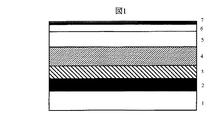
次に、本発明の実施形態について詳細に説明する。図1に本発明の実施形態の一例を示す。
【0030】
<実施形態1>
まず、用いるソーダライムガラス基体1の(外径84mm、内径25mm、厚さ1.1mm)洗浄を十分行なった。これを約5.3×10E−5Pa(4.0×10E−7Torr)まで排気された真空層内に導入した。最初に、第1シード層形成室に搬送しAr雰囲気約0.8Pa(6mTorr)の条件下でDCマグネトロンスパッタリング法によりNi−25at.%Cr−15at.%Zr第1シード層2を20nm形成した。続いて,第2シード層形成室に搬送しAr雰囲気約0.8Pa(6mTorr)の条件下でDCマグネトロンスパッタリング法によりCo−40at.%Cr−5at.%Zr第2シード層3を50nm形成した。次に真空層内の加熱室に搬送し、IRヒータ(赤外線ヒータ)により基板温度を260°Cに加熱した。
【0031】
続いて、下地層形成室に搬送し、Ar雰囲気約0.8Pa(6mTorr)の条件下でDCマグネトロンスパッタリング法によりCr−10at.%Mo−7. 5at.%Ti合金下地層4を30nm成膜した。続いて磁気記録層形成室に搬送し、Ar雰囲気約0.9Pa(7mTorr)の条件下でDCマグネトロンスパッタリング法により、Co−20at.%Cr−4at.%Ta−8at.% Pt合金層5(磁性層を形成する)を22nm形成した。この、Cr−10at.%Mo−7.5at.%Ti合金下地層2、Co−20at.%Cr−4at.%Ta−8at.%Pt合金層5まで形成した基板を用い、以下に述べる本発明に関わるカーボンを主成分とする保護膜層を形成した。
【0032】
前記基板1としては、ソーダライムガラスの他に、化学強化したアルミノシリケート、 Ni−Pを無電解めっきしたAl−Mg合金基板、シリコン、硼珪酸ガラス等からなるセラミックス、または、ガラスグレージングを施したセラミックス等からなる非磁性の剛体基板等を用いることができる。
【0033】
第1及び第2シード層はソーダライムガラスからのアルカリ金属の電気化学的析出を防ぐために設けてあるもので,厚さは任意でありどちらか片方でもかまわない。また,特に用いる必要がなければ省略することもできる。下地層4はその上に形成する磁性層の結晶配向性を制御する下地膜として用いられる。下地層としては、磁性膜と結晶整合性の良い(100)配向させることも可能な不規則固溶体を形成する非磁性のCr−V,Cr−Ti,Cr−Mo, Cr−Si,Cr−Mo−Ti合金等のCr基合金の薄膜を用いることもできる。スパッタで用いる放電用のガスに0.5体積%から50体積%の窒素を同時に添加して下地層を形成すると下地層の結晶粒が微細化した。その結果、連続して形成する磁性層の結晶粒も微細化し、媒体ノイズを低減できた。
【0034】
磁性層5としては、Co−Cr−Pt−Ta合金だけでなく、Coを主成分とし、保磁力を高めるためにPtを含有し、さらに媒体ノイズを低減するためCr, Ta,SiO2,Nb等を添加した多元の合金系を用いることができる。特にTa,Nb,V,Tiを添加するとターゲットの融点が下がり、Crを含有した磁性膜の組成分離が進行しやすくなり好ましかった。
【0035】
Pt,NiあるいはMnを添加したCo基合金系では磁気異方性エネルギーの低下が他の添加元素に比べて少なく実用的である。具体的には、Co−Cr−Ptの他に、Co−Cr−Pt−Ta,Co−Cr−Pt−SiO2,Co−Cr−Pt−Mn,Co−Cr−Nb−Pt,Co−Cr−V−Pt,Co−Cr−Ti−Pt,Co−Cr−Nb−Ta−Pt,Co−Pt−Ni−SiO2等の合金を用いることができる。
【0036】
強磁性の部分を占めるCo合金層の組成に関し、Crの固溶限は5〜10at.%、Taの固溶限は約2at.%であると考えられ、これらの固溶限を超えてCo合金磁性層を形成することにより、磁性層における磁気的な分離が進行し、媒体ノイズが低減する。実用的な組成として、例えば、
Co−20at.%Cr−4at.%Ta−8at.%Pt合金、
Co−22at.%Cr−20at.%Pt合金、
Co−15at.%Cr−8at.%Pt−20mol.%SiO2合金、
Co−17at.%Cr−12at.%Pt−5at.%Mn合金、
Co−17at.%Cr−5at.%Nb−10at.%Pt合金、
Co−20at.%Cr−5at.%V−12at.%Pt合金、
Co−20at.%Cr−10at.%−15at.%Pt合金、
Co−15at.%Cr−5at.%Nb−5at.%Ta−20at.%Pt合金、等を用いることができる。
【0037】
上記基板を真空層内から出すことなく図2に示す保護膜層形成室21に搬送した。この保護膜層形成室21は熱フィラメント22とアノード23及び熱フィラメント前方に配置したグリッド24からなるイオンガンからなる。この保護膜層形成室21をターボモレキュラポンプで排気しながら,アノード後方からArガスを15sccm(Standard Cubic centimeter per minutes)とエチレン(C2H4)ガスを50sccm,さらに二酸化炭素(CO2)ガスを20sccm,二酸化窒素(NO2)ガスを10sccm,笑気ガス(N2O)10sccm をマスフローコントローラを介し導入した。このときの圧力はバラトロンゲージで約0.5Pa(4mTorr)であった。
【0038】
次いで、基板の両サイドに位置したイオンガンの熱フィラメントに30A,アノードに直流+100Vを印加しプラズマを誘引した。そして、グリッドに-530Vを印加してイオンを引き出した。さらに、基板には-100V,3kHzのパルスバイアスを付与した。このときのアノード電流は500mA,基板のバイアス電流は50mAであった。このイオンビームデポジション法(IBD)により、Co-Cr-Ta-Pt 合金層5の上に炭素と水素を主成分とするDLC保護膜層6を3nm形成した。このときの膜の堆積速度は、1.0nm/sであった。
【0039】
上述した手法によりディスクを複数枚作製し、あるものは薄膜の分析を行い、あるものはフルオロカーボン系の潤滑剤層7を設けた。この厚みはフーリエトランスファー赤外分光分析装置(FT-IR)で定量したところ2.2nmであった。その後浮上チェックを行ない単板での摺動試験、もしくは磁気ディスク装置に組み込み信頼性試験を行った。
【0040】
上記手法により作製したディスクの保護膜を以下の手法より分析し保護膜表面の官能基の割合を定量した。すなわち、保護膜表面の官能基の被覆率同定にはESCA(Electron Spectroscopy for Chemical Analysis)を用いた。ESCAによる表面官能基である-COOH, -C=O, -COH, -CNH2の直接同定は感度および測定 精度の観点から定量的な同定が困難である。上記問題点は以下に記すtag修飾法により克服した。
【0041】
すなわち、保護膜表面官能基と定量的かつ不可逆的に分子認識により反応を行う官 能基を有する、ESCAに感度係数の高い、フッ素原子を含む分子で修飾(tag修飾)する ことによる被覆率同定を行った。
【0042】
具体的には、
・-COOH官能基の同定には保護膜表面をペンタフルオロフェニルブロマイドをベンゼ ン溶液中で1時間浸し、-COOH官能基をフッ素分子により修飾した。
【0043】
・-C=O官能基の同定には保護膜表面をペンタフルオロフェニルヒドラジンをエタノール溶液中で1時間浸し、-C=O官能基をフッ素分子により修飾した。
【0044】
・-COH官能基の同定には保護膜表面をパーフルオロオクチルジメチルクロロシランをエタノール溶液中で1時間浸し、-COH官能基をフッ素分子により修飾した。
【0045】
・-CNH2官能基の同定には保護膜表面をペンタフルオロベンゾイルクロライドをクロロホルム溶液中で1時間浸し、-CNH2官能基をフッ素分子により修飾した。
【0046】
室温にてそれぞれ1時間の反応によりtag修飾された各保護膜表面はそれぞれの溶媒に浸漬され未反応物が保護膜表面から除去された。
【0047】
保護膜表面の官能基被覆率同定には各tag修飾された保護膜表面をESCAによる24゜の分析角度で、C1sとF1s測定強度比により求めたその結果,カーボン原子100個当たりの-COOH,-C=O,-COH,-CNH2の官能基の比率は合計で平均約30%であった。
【0048】
一方、潤滑剤まで設けたディスクをヘッドのロード/アンロード機構を備えた評価装置に装着し試験を行なった。10枚のディスクを回転数15000r. p.mでロードアンロード試験 50000回行ったところ、10枚ともクラッシュすることなく試験を終了した。さらに試験後のディスクの潤滑層厚みをFT-IRで測定したところ2.1nm とほとんど減少していないことが確認できた。この結果、本発明による磁気記録媒体は潤滑剤との結合力が強く回転飛散による潤滑剤減少量が少なく,保護膜の厚さが3nmと極めて薄い場合においても耐摺動信頼性が十分であることが証明された。以上の評価結果はサンプルNo.1として、図3に記載する。
【0049】
<比較例>
保護膜層6を形成する際に二酸化炭素(CO2)ガス,二酸化窒素(NO2)ガスを10sccm,笑気ガスを加えなかったことを除いては実施形態1と略同一の製法でサンプルNo.2を作製した。保護膜層6の厚みは実施形態1と同様の3nm、潤滑層7の厚みも同様に2.2nmであった。このようにして作成したディスクを実施形態1と同様の手法で評価を行なった。
【0050】
その結果、 tag修飾法による分析では表面官能基の割合が13%であった。また,10枚のディスクを回転数15000r. p.mでロードアンロード試験を行ったところ、全てのディスクが1000回から8000回の間でクラッシュに至った。さらにその10枚のディスクの潤滑層厚みを(FT-IR)にて測定したところ0.7から1.2nmと試験前と比較して減少していることが確認できた。
【0051】
この結果、比較例の作成方法によって得られる磁気記録媒体は保護膜層と潤滑層の結合力が十分ではないために高速回転により潤滑層が飛散減少し磁気記録媒体と磁気ヘッドの摩擦力が増加することでクラッシュに至ることが判明した。
【0052】
<実施形態2>
前記実施形態1に記載した円板について、5万回のロード/アンロードを実施した結果、磁性膜の厚さを15nm、17nm、21nmとしたいずれの磁気記録媒体においても、磁気記録媒体および磁気ヘッドが破壊されることはなく、良好な耐摺動信頼性が得られた。
【0053】
磁性層の厚さを薄くすることにより、磁性層の厚さtと残留磁束密度Brとの積Br×tが大きく減少した。面内保磁力Hcはおおむね176kA/mから256kA/m、保磁力角型比S*は0.74から0.65で0.7前後、角型比Sは0.78から0.7であった(角型比Sは飽和磁束密度に対する残留磁束密度の割合)。これらの磁気特性は試料振動型磁力計により25°Cで測定した。
【0054】
これらの磁気記録媒体の電磁変換特性を磁気抵抗効果型再生素子(MR素子)のシールドギャップ長Gsが0.12μm、書き込み素子のギャップ長が0.2μmの磁気ヘッドを用いて測定した。MR素子のセンス電流は3mA、書き込み電流Iは41mAとした。磁気記録媒体(磁気ディスク媒体)の回転数を変化させ、ヘッドの浮上量を変えて、デジタルオシロスコープ(TektronixTDS544A)により孤立再生波の出力半値幅PW50を測定した。
【0055】
磁性膜が薄いほど、また、磁気ヘッドの浮上量が低いほどPW50は小さくなっており、磁性膜の厚さが15nmでヘッドの浮上量が25nmの場合に、240nmという小さな値が得られた。スペクトルアナライザで測定した最高線記録密度360kFCIにおける出力は、デジタルオシロスコープで測定した10kFCIにおける孤立再生波の出力に対して1〜2 %であった。スペクトルアナライザで測定した最高線記録密度360kFCIにおける出力は、奇数次の波形の出力を100MHzを超えるまで積算して求めた。
【0056】
さらに、孤立再生波の0−p出力(SLF)と360kFCIの信号を記録した場合の積算媒体ノイズ(Nd)の比SLF/Ndを評価した。ここで、ヘッドの浮上量は25 nmとし、Ndは0.5kFCIから540kFCIに相当する帯域のノイズを積算した値とした。何れの媒体も、360kFCIという高い記録密度において24dB以上の高いSLF/Nd比が得られた。
【0057】
これらの磁気ディスク媒体61と、前記磁気記録媒体を駆動する駆動部62と、記録部と再生部からなる磁気ヘッド63と、前記磁気ヘッドを上記磁気記録媒体に対して相対運動させる手段64と、前記磁気ヘッドへの信号入力手段と前記磁気ヘッドからの出力信号再生を行なうための記録再生信号処理手段65と前期磁気ヘッドのロードアンロード時の退避場所となる66を有する磁気記憶装置を図4に示すように構成した。
【0058】
前記磁気ヘッドの再生部が磁気抵抗効果型磁気ヘッドで構成されるようにした。測定に用いた磁気ヘッドの模式的斜視図を図5に示す。このヘッドは基体601上に形成された記録用の電磁誘導型ヘッドと再生用の磁気抵抗効果型ヘッドを併せ持つ複合型ヘッドである。前記記録ヘッドはコイル602を挟む上部記録磁極603と下部記録磁極兼上部シールド層604からなり、記録磁極間のギャップ長は0.3μmとした。また、コイルには厚さ3μmの銅を用いた。前記再生用ヘッドは磁気抵抗センサ605とその両端の電極パターン606からなり、磁気抵抗センサは共に1μm厚の下部記録磁極兼上部シールド層604と下部シールド層607で挟まれ、前記シールド層間距離は0.20μmである。尚、図6では記録磁極間のギャップ層、及びシールド層と磁気抵抗センサとのギャップ層は省略してある。
【0059】
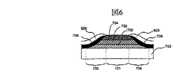
図6に磁気抵抗センサの断面構造を示す。磁気センサの信号検出領域701は、酸化アルミニウムのギャップ層700上に横バイアス層702、分離層703、磁気抵抗強磁性層704が順次形成された部分からなる。磁気抵抗強磁性層704には、20nmのNi−Fe合金を用いた。横バイアス層702には25nmのNi−Fe−Nb合金を用いたが、Ni−Fe−Rh等の比較的電気抵抗が高く、軟磁気特性の良好な強磁性合金であれば良い。
【0060】
横バイアス層702は磁気抵抗強磁性層704を流れるセンス電流が作る磁界によって、前記電流と垂直な膜面内方向(横方向)に磁化され、磁気抵抗強磁性層704に横方向のバイアス磁界を印加する。これによって、媒体61からの漏洩磁界に対して線形な再生出力を示す磁気センサが選られる。磁気抵抗強磁性層704からのセンス電流の分流を防ぐ分離層703には、比較的電気抵抗が高いTaを用い、膜厚は5nmとした。
【0061】
信号検出領域の両端にはテーパー形状に加工されたテーパー部705がある。
【0062】
テーパー部705は、磁気抵抗強磁性層704を単磁区化するための永久磁石層706と、その上に形成された信号を取り出すための一対の電極606からなる。永久磁石層706は保磁力が大きく、磁化方向が容易に変化しないことが必要であり、Co−Cr,Co−Cr−Pt等の合金が用いられる。
【0063】
実施形態1に記載した磁気記録媒体と、図5に示した上記ヘッドと組み合わせて、図4に示す磁気記憶装置を構成した。その結果、磁気的な浮上高さhmが48〜60nm程度の浮上系では、磁性層の厚さtと記録時における前記磁気記録媒体に対する前記磁気ヘッドの相対的な走行方向に磁界を印加して測定した残留磁束密度Brとの積Br×tが9.6mA(120ガウス・ミクロン)を超えると十分な書き込みができずオーバーライト(重ね書き)特性が劣化し、特に高線記録密度領域での出力も低下した。
【0064】
一方、Br×tが3.2mA(40ガウス・ミクロン)よりも小さくなると、媒体の記録層の組成或いは厚さによっては、4日間70°Cに放置して再生出力の減少が認められる場合があった。よって実施形態1に記載した磁気記録媒体で述べた磁性層の厚さtと記録時における前記磁気記録媒体に対する前記磁気ヘッドの相対的な走行方向に磁界を印加して測定した残留磁束密度Brとの積Br×tが3.2mA(40ガウス・ミクロン)以上9.6mA(120ガウス・ミクロン)以下であるようにして磁気記憶装置を構成した。
【0065】
前記磁気抵抗効果型磁気ヘッドの磁気抵抗センサ部が、互いに0.2μmを超えた距離だけ隔てられた軟磁性体からなる2枚のシールド層の間に形成されたヘッドを用いた場合には、最高線記録密度が250kFCIを超えると十分な再生出力が得られなかった。軟磁性体からなる2枚のシールド層の距離は0.12μmを下回ると、プロセス加工上の困難さから容易に素子形成ができなかった。これらの結果から、0.12μm以上0.2μm以下の距離だけ隔てられた軟磁性体からなる2枚のシールド層の間に形成されたヘッドを用いて磁気記憶装置を構成した。このようにして構成した磁気記憶装置によって、1平方インチ当たり50ギガビット以上の記録密度を実現することができた。
【0066】
<実施形態3>
前記実施形態2で用いた磁気抵抗効果型磁気ヘッドの代わりに、実施形態2に記載の磁気抵抗効果型磁気ヘッド63が、互いの磁化方向が外部磁界によって相対的に変化することによって大きな抵抗変化を生じる複数の導電性磁性層と、この導電性磁性層の間に配置された導電性非磁性層を含む磁気抵抗センサによって構成される磁気ヘッドを用いた以外は、図4と同一の構成で磁気記憶装置を構成した。
【0067】
図7に用いたセンサの断面図を示す。このセンサはギャップ層608上に、5nmのTaバッファ層801、7nmの第1の磁性層802、1.5nmの銅からなる中間層803、3nmの第2の磁性層804、10nmのFe−50at.%Mn反強磁性合金層805が順次形成された構造である。前記第1の磁性層802にはNi−20at.%Fe合金を使用し、第2の磁性層804にはコバルトを使用した。
【0068】
反強磁性層805からの交換磁界により、第2の磁性層804の磁化は一方向に固定されている。これに対し、第2の磁性層804と非磁性層803を介して接する第1の磁性層802の磁化の方向は、磁気記録媒体61からの漏洩磁界により変化するため、抵抗変化が生じる。
【0069】
このような2つの磁性層の磁化の相対的方向の変化に伴う抵抗変化はスピンバルブ効果と呼ばれる。本実施形態では再生用ヘッドにこの効果を利用したスピンバルブ型磁気ヘッドを使用した。テーパー部705は実施形態2の磁気センサと同一構成である。
【0070】
測定に用いた磁気記録媒体のBr×tは3,3.2,4,6,8,10,12,14mAとした。Br×tを3mA(37.5ガウスミクロン)とした場合には、再生信号の時間経過に伴う低下が甚だしく、また、実用上好ましい保磁力を得ることが難しかった。 Br×tは12mA(150ガウスミクロン)を超えると、2Fの出力は大きいものの出力分解能が低下する傾向が顕著になるため好ましくないことが明らかになった。
【0071】
また、このようなスピンバルブ型の再生ヘッドを用いると、実施形態2で述べたように360kFCIを超える最高線記録密度で記録した信号を安定して再生し信号出力を得られた。
【0072】
ここで示したヘッドは、実施形態2で用いたヘッドと同一のものであり、磁気抵抗効果型磁気ヘッドが、浮上面レールの面積が1.4mm2以下であり、質量が2mg以下の磁気ヘッドスライダー上に形成されていた。浮上面レールの面積が1.4mm2以下であるのは、前述した突起と衝突する確率を低減し、同時に質量が2mg以下とすることにより、耐衝撃信頼性を向上できるた。これにより、高い記録密度と高い衝撃性を両立させることができ、1平方インチ当たり50ギガビット以上の記録密度で30万時間以上の平均故障時間間隔(MTBF)が実現ができた。
【0073】
【発明の効果】
本発明によれば、保護膜と潤滑膜の結合性を上昇させることができる。さらには本磁気記録媒体と磁気ヘッドを組み合わせることにより大容量高信頼性の磁気ディスク装置を提供することが出来る。
【図面の簡単な説明】
【図1】本発明の実施形態に係る磁気記録媒体の断面模式図である。
【図2】保護膜形成室21の概略図である。
【図3】本発明の実施形態と比較例により供される磁気記録媒体の性能比較図である。
【図4】磁気記憶装置の全体構成を示す図である。
【図5】磁気ヘッドの模式的斜視図である。
【図6】磁気抵抗センサの断面構造を示す図である。
【図7】スピンバルブ型磁気ヘッドを用いたセンサの断面図である。
【符号の説明】
1…非磁性基板、2…Ni合金シード層、3…Co合金シード層、4…Cr合金下地層、5…Co合金磁性層、6…保護膜層、7…潤滑層、21…保護膜形成室、22…保護膜形成室、23…スパッタ粒子遮蔽物、24…スパッタ粒子遮蔽物、61…磁気ディスク媒体、 62…磁気記録媒体を駆動する駆動部、63…記録部と再生部からなる磁気ヘッド、 64…磁気ヘッドを上記磁気記録媒体に対して相対運動させる手段、65…磁気ヘッドへの信号入力手段と出力信号再生を行なうための記録再生信号処理手段、66…磁気ヘッドのロードアンロード時退避場所、601…基体、602…コイル、603…上部記録磁極、604…下部記録磁極兼上部シールド層、605…磁気抵抗センサ、606…磁気抵抗センサの両端の電極パターン、607…下部シールド層、608…ギャップ層、
700…酸化アルミニウムのギャップ層、701…磁気センサの信号検出領域、702 …横バイアス層、703…センス電流の分流を防ぐ分離層、704…磁気抵抗強磁性層、 705…テーパー形状に加工されたテーパー部、706…永久磁石層、801…Taバッファ層、802…第1の磁性層、803…銅からなる非磁性中間層、804…第2の磁性層、805…反強磁性合金層。[0001]
BACKGROUND OF THE INVENTION
The present invention relates to a magnetic recording medium having excellent reliability and capable of high-density magnetic recording, a manufacturing method thereof, and a magnetic disk device used for an auxiliary storage device of a computer.
[0002]
[Prior art]
Magnetic disk devices used for storage devices such as large computers, workstations, and personal computers are becoming increasingly important year by year, and have been developed to have a large capacity and a small size. Increasing the density is indispensable for reducing the capacity and size of the magnetic disk device, and a technique for realizing this is to reduce the distance between the magnetic recording layer of the magnetic recording medium and the magnetic head.
[0003]
2. Description of the Related Art Conventionally, a magnetic recording medium manufactured using sputtering is provided with a protective film for the purpose of protecting the magnetic film from sliding with a magnetic head. Thinning the protective film and reducing the distance between the surface of the protective film and the magnetic head are the most effective means for reducing the distance between the magnetic recording layer and the magnetic head. For this protective film, carbon produced by DC sputtering, RF sputtering (JP-A-5-174369), CVD (JP-A-4-90125) is most commonly used, and has higher strength. In order to obtain a protective film, a method of incorporating nitrogen atoms, hydrogen atoms, etc. into the film (Japanese Patent Laid-Open No. 62-246129) has been generally employed. Further, a perfluoropolyether liquid lubricant is generally used on the protective film for the purpose of reducing friction between the magnetic head and the magnetic recording medium.
[0004]
As a general method for thinning the film, the protective film may be diamond-like carbon (DLC) using ion beam deposition (IBD) or chemical vapor deposition (CVD). However, DLC generally has a strong bonding force between carbon atoms and hydrogen atoms in a thin film, and its network has higher continuity than a carbon protective film provided by sputtering. Therefore, there is a problem that the functional groups on the film surface and the film surface are few and the binding force with the perfluoropolyether lubricant imparted on the protective film is weak.
[0005]
One of the performance indicators of a magnetic recording apparatus using the magnetic recording medium is a data transfer speed. This transfer rate largely depends on the data access time. The access time consists of a seek time and a rotation waiting time, and shortening the rotation waiting time by increasing the rotation speed of the magnetic recording medium leads to an improvement in the data transfer speed.
[0006]
However, when the rotational speed of the magnetic recording medium is increased, the centrifugal force acts on the liquid lubricant on the DLC protective film of the magnetic recording medium, and as a result of the problem that the coupling force is weak as described above, the liquid lubricant is removed from the outer periphery of the magnetic recording medium. At last, the magnetic recording medium is swung away from the magnetic recording medium (hereinafter referred to as rotational scattering). As a result, there is a problem that the lubricant on the magnetic recording medium is reduced, resulting in an increase in frictional force between the magnetic recording medium and the magnetic head and a crash.
[0007]
In order to prevent this, an attempt has been made to increase the binding force by subjecting the protective film to a surface treatment. In JP-A-62-150526 and JP-A-63-2117, the surface is subjected to plasma treatment. In Japanese Patent Laid-Open No. 4-6624, the surface is subjected to ultraviolet treatment, water treatment, ozone treatment and the like. Also, JP-A-62-2117, JP-A-9-30596, JP-A-8-225791, JP-A-7-210850, JP-A-5-174354, etc. are the same as the above, and these are all after the protective film is formed. The surface is subjected to some treatment. However, these methods have a problem that it is difficult to uniformly treat the entire surface, and the number of operations is increased by one step, and the adhesion of the lubricant is insufficient.
[0008]
[Problems to be solved by the invention]
The present invention has been made with the above problems in mind.
[0009]
A first object of the present invention is to provide a magnetic recording medium that increases the chemical bonding force between a protective film layer and a liquid lubricant and does not cause a decrease in the liquid lubricant due to rotational scattering even under high-speed rotation.
[0010]
A second object of the present invention is to provide a method of manufacturing a magnetic recording medium that can achieve the first object.
[0011]
A third object is to provide a magnetic storage device suitable for achieving both high-speed rotation and high reliability using a magnetic recording medium that achieves the second object.
[0012]
[Means for Solving the Problems]
In order to solve the above problems, the present invention mainly adopts the following configuration.
[0013]
The magnetic recording medium of the present invention comprises carbon atoms in a diamond-like carbon protective film containing carbon as a main component of a magnetic recording medium having a magnetic film on a nonmagnetic substrate through at least an underlayer. It is characterized in that the ratio of functional groups per unit exceeds 20%.
[0014]
When a lubricating film of perfluoropolyether having at least one functional group is provided on the protective film, the bondability between the protective film and the lubricating film is excellent.
[0015]
The method for producing a magnetic recording medium of the present invention is a method for producing a magnetic recording medium having a magnetic film on a nonmagnetic substrate with at least an underlayer interposed therebetween. When forming a film by the beam method or chemical vapor deposition method, 2 , NO 2 , N 2 At least one gas of O is added.
[0016]
When the protective film is diamond-like carbon, the bondability between the protective film and the lubricating film is particularly improved.
[0017]
When forming a protective film by the above ion beam method or chemical vapor deposition method, 2 , Ne, Ar, Kr, Xe and a hydrocarbon gas or a hydrocarbon gas are preferably used.
[0018]
In a method of manufacturing a magnetic recording medium having a magnetic film on at least an underlayer on a nonmagnetic substrate, a diamond-like carbon protective film mainly composed of carbon that protects the magnetic film is formed by an ion beam method or a chemical vapor deposition method. When depositing with CO 2 , NO 2 , N 2 At least one gas of O may be added.
[0019]
The magnetic storage device of the present invention includes the magnetic recording medium, a drive unit that drives the magnetic recording medium, a magnetic head that includes a recording unit and a reproducing unit, and a recording that exchanges signals with the magnetic head. A reproduction signal processing unit and a magnetoresistive effect type magnetic head as a reproduction unit of the magnetic head are provided.
[0020]
DETAILED DESCRIPTION OF THE INVENTION
First, an outline of the configuration, function, and operation of the present invention will be described below. In the method for producing a magnetic recording medium, a magnetic film, a protective film mainly composed of carbon (carbon) protecting the magnetic film, and a lubricating film of perfluoropolyether having at least one functional group are provided on a substrate. N protective film 2 When forming a film by ion beam method or CVD method using only hydrocarbon gas or hydrocarbon gas and at least one of N, Ar, Kr, and Xe 2 , NO 2 , N 2 By adding at least one gas of O, the bonding property between the protective film and the lubricating film is increased.
[0021]
In the magnetic recording medium provided by the above method, the ratio of functional groups per 100 carbon atoms in the protective film can exceed 20%.
[0022]
The magnetic storage device of the present invention includes a magnetic recording medium, a driving unit that drives the magnetic recording medium, a magnetic head that includes a recording unit and a reproducing unit, and a relative movement of the magnetic head with respect to the magnetic recording medium. And a recording / reproducing signal processing means for reproducing an output signal from the magnetic head, wherein the reproducing unit of the magnetic head is a magnetoresistive effect type magnetic head. And the magnetic recording medium is realized by the magnetic recording medium having the characteristics as described above and having the film quality, hardness, and film thickness of the protective film.
[0023]
Further, the magnetoresistive sensor portion of the magnetoresistive head is formed between two shield layers made of a soft magnetic material separated from each other by a distance of 0.2 μm or less, and has the configuration described above. The product Br × t of the magnetic layer thickness t of the magnetic recording medium to be taken and the residual magnetic flux density Br measured by applying a magnetic field in the direction of travel of the magnetic head relative to the magnetic recording medium during recording is 3. It is configured to be 2 mA (40 gauss microns) or more and 9.6 mA (120 gauss microns) or less.
[0024]
The magnetoresistive sensor portion of the magnetoresistive head must be formed between two shield layers made of a soft magnetic material separated from each other by a distance of 0.2 μm or less. This is because a sufficient reproduction output cannot be obtained in a magnetic storage device having a current exceeding 220 kFCI. The distance between the two shield layers made of a soft magnetic material is preferably 0.12 μm or more for ease of work.
[0025]
The product Br × the product of the thickness t of the magnetic layer of the magnetic recording medium having the above-described configuration and the residual magnetic flux density Br measured by applying a magnetic field in the direction of travel of the magnetic head relative to the magnetic recording medium during recording. t is 3.2 mA (40 gauss microns) or more and 9.6 mA (120 gauss microns) or less. When Br × t is 3.2 mA (40 gauss microns), the reproduction output is left for a long time after recording. This is because there is a high risk that erroneous information will be reproduced due to a decrease in the recording medium, and overwriting at 9.6 mA (120 gauss / micron) makes it difficult to overwrite at the time of recording.
[0026]
Furthermore, the crystal orientation of the magnetic layer can be controlled by forming at least two underlayers of the magnetic recording medium. By forming this multilayer underlayer, the influence of atomic diffusion from the underlayer to the magnetic layer can be greatly reduced, and at the same time the crystallinity of the underlayer adjacent to the magnetic layer can be improved, and the adhesion between the magnetic layer and the underlayer is also improved. Strengthens and high sliding resistance is obtained. Furthermore, since the surface of the underlayer adjacent to the magnetic layer does not have a periodic arrangement of atoms over a long distance, the crystal grains of the magnetic layer formed thereon can be miniaturized and the crystal orientation can also be controlled. It becomes possible. As a result, the average grain size of crystals constituting the magnetic layer is controlled to a fine size of 15 nm or less suitable for low noise, and at the same time, the direction of the easy axis of magnetization is parallel to the film surface suitable for in-plane magnetic recording. Can be controlled in the direction.
[0027]
In addition, the magnetoresistive head used in the magnetic storage device of the present invention includes a plurality of conductive magnetic layers that cause a large change in resistance due to relative changes in the magnetization directions of each other by an external magnetic field, and the conductive magnetic layer. The magnetoresistive sensor includes a conductive nonmagnetic layer disposed between the layers. The use of such a reproducing head is used to stably reproduce a signal recorded at a maximum linear recording density exceeding 300 kFCI and obtain a signal output.
[0028]
Furthermore, the present invention is achieved by forming the magnetoresistive head on a magnetic head slider having an air bearing surface rail area of 1.00 mm @ 2 or less and a mass of 2 mg or less. The area of the air bearing surface rail is 1.00 mm @ 2 or less because the probability of colliding with the above-mentioned protrusion is reduced, and at the same time the mass is made 2 mg or less, thereby improving the impact resistance reliability. This makes it possible to achieve both a recording density of 50 gigabits or more per square inch and high impact properties.
[0029]
Next, an embodiment of the present invention will be described in detail. FIG. 1 shows an example of an embodiment of the present invention.
[0030]
<Embodiment 1>
First, the soda lime glass substrate 1 to be used was sufficiently washed (outer diameter 84 mm,
[0031]
Subsequently, the film was transferred to the underlayer forming chamber, and Cr-10 at. Was obtained by DC magnetron sputtering under an Ar atmosphere of about 0.8 Pa (6 mTorr). % Mo-7. 5 at. % Ti alloy underlayer 4 was deposited to a thickness of 30 nm. Subsequently, the film was transported to the magnetic recording layer forming chamber, and was subjected to a Co-20 at. By DC magnetron sputtering under an Ar atmosphere of about 0.9 Pa (7 mTorr). % Cr-4 at. % Ta-8 at. % Pt alloy layer 5 (forming a magnetic layer) was formed to 22 nm. This Cr-10 at. % Mo-7.5 at. %
[0032]
As the substrate 1, in addition to soda lime glass, chemically strengthened aluminosilicate, an Al—Mg alloy substrate electrolessly plated with Ni—P, ceramics made of silicon, borosilicate glass, or the like, or glass glazing was applied. A nonmagnetic rigid substrate made of ceramics or the like can be used.
[0033]
The first and second seed layers are provided in order to prevent electrochemical precipitation of alkali metal from soda lime glass, and the thickness is arbitrary and either one may be used. It can also be omitted if it is not necessary to use it. The underlayer 4 is used as an underlayer for controlling the crystal orientation of the magnetic layer formed thereon. As the underlayer, nonmagnetic Cr—V, Cr—Ti, Cr—Mo, Cr—Si, Cr—Mo forming an irregular solid solution that can be (100) oriented with good crystal matching with the magnetic film. A thin film of a Cr-based alloy such as a Ti alloy can also be used. When an underlayer was formed by simultaneously adding 0.5 vol% to 50 vol% nitrogen to the discharge gas used in sputtering, the crystal grains of the underlayer were refined. As a result, the crystal grains of the magnetic layer formed continuously were made finer, and the medium noise could be reduced.
[0034]
The magnetic layer 5 is not only a Co—Cr—Pt—Ta alloy, but also contains Co as a main component, contains Pt to increase the coercive force, and further reduces media noise such as Cr, Ta,
[0035]
A Co-based alloy system to which Pt, Ni, or Mn is added is practical because there is less decrease in magnetic anisotropy energy than other additive elements. Specifically, in addition to Co—Cr—Pt, Co—Cr—Pt—Ta, Co—Cr—Pt—
[0036]
Regarding the composition of the Co alloy layer occupying the ferromagnetic portion, the solid solubility limit of Cr is 5 to 10 at. %, The solid solubility limit of Ta is about 2 at. When the Co alloy magnetic layer is formed beyond these solid solubility limits, magnetic separation in the magnetic layer proceeds and medium noise is reduced. As a practical composition, for example,
Co-20 at. % Cr-4 at. % Ta-8 at. % Pt alloy,
Co-22 at. % Cr-20 at. % Pt alloy,
Co-15 at. % Cr-8 at. % Pt-20 mol. % SiO2 alloy,
Co-17 at. % Cr-12 at. % Pt-5 at. % Mn alloy,
Co-17 at. % Cr-5 at. % Nb-10 at. % Pt alloy,
Co-20 at. % Cr-5 at. % V-12 at. % Pt alloy,
Co-20 at. % Cr-10 at. % -15 at. % Pt alloy,
Co-15 at. % Cr-5 at. % Nb-5 at. % Ta-20 at. % Pt alloy or the like can be used.
[0037]
The substrate was transferred to the protective film
[0038]
Next, plasma was induced by applying 30 A to the hot filament of the ion gun located on both sides of the substrate and +100 V DC to the anode. Then, −530 V was applied to the grid to extract ions. In addition, a -100V, 3kHz pulse bias was applied to the substrate. At this time, the anode current was 500 mA, and the substrate bias current was 50 mA. By this ion beam deposition method (IBD), a DLC
[0039]
A plurality of discs were prepared by the above-described method, and in some cases, the thin film was analyzed, and in some cases, a fluorocarbon-based lubricant layer 7 was provided. This thickness was determined to be 2.2 nm by quantification using a Fourier transfer infrared spectrometer (FT-IR). After that, a floating check was performed, and a sliding test with a single plate or a built-in magnetic disk unit was tested for reliability.
[0040]
The protective film of the disk produced by the above method was analyzed by the following method, and the ratio of functional groups on the surface of the protective film was quantified. That is, ESCA (Electron Spectroscopy for Chemical Analysis) was used to identify the functional group coverage on the surface of the protective film. Direct identification of -COOH, -C = O, -COH, -CNH2 which are surface functional groups by ESCA is difficult to quantitatively identify from the viewpoint of sensitivity and measurement accuracy. The above problems were overcome by the tag modification method described below.
[0041]
In other words, the coverage is identified by modifying (tag modification) with a molecule containing a fluorine atom that has a functional group that reacts quantitatively and irreversibly with functional groups on the surface of the protective film and has a high sensitivity coefficient to ESCA. Went.
[0042]
In particular,
・ To identify the -COOH functional group, the surface of the protective film was immersed in benzene solution for 1 hour with pentafluorophenyl bromide, and the -COOH functional group was modified with fluorine molecules.
[0043]
-To identify the -C = O functional group, the surface of the protective film was immersed in pentafluorophenylhydrazine in an ethanol solution for 1 hour, and the -C = O functional group was modified with fluorine molecules.
[0044]
・ To identify -COH functional group, perfluorooctyldimethylchlorosilane was immersed in ethanol solution for 1 hour on the surface of the protective film, and -COH functional group was modified with fluorine molecules.
[0045]
・ To identify -CNH2 functional group, pentafluorobenzoyl chloride was immersed in chloroform solution for 1 hour on the protective film surface, and -CNH2 functional group was modified with fluorine molecules.
[0046]
The surface of each protective film that was tag-modified by reaction for 1 hour at room temperature was immersed in the respective solvent, and unreacted substances were removed from the surface of the protective film.
[0047]
To identify the functional group coverage on the surface of the protective film, the surface of the protective film modified with each tag was determined from the measured intensity ratio of C1s and F1s at an analysis angle of 24 ° by ESCA. The ratio of functional groups of -C = O, -COH, -CNH2 was about 30% on average in total.
[0048]
On the other hand, a disk provided with a lubricant was mounted on an evaluation apparatus equipped with a head loading / unloading mechanism and tested. 10 discs with 15000 rpm. p. When the load / unload test was performed 50000 times at m, the test was completed without crashing all 10 sheets. Furthermore, when the lubrication layer thickness of the disc after the test was measured by FT-IR, it was confirmed that there was almost no decrease at 2.1 nm. As a result, the magnetic recording medium according to the present invention has a strong binding force to the lubricant and a small amount of lubricant decrease due to rotational scattering, and has sufficient sliding resistance reliability even when the protective film is as thin as 3 nm. It was proved. The above evaluation results are shown in Sample No. This is shown in FIG.
[0049]
<Comparative example>
When forming the
[0050]
As a result, the analysis by the tag modification method revealed that the surface functional group ratio was 13%. In addition, 10 discs were rotated at 15000 rpm. p. When a load / unload test was performed at m, all disks crashed between 1000 and 8000 times. Furthermore, the lubricating layer thickness of the 10 disks was measured by (FT-IR), and it was confirmed that the thickness was reduced from 0.7 to 1.2 nm compared to before the test.
[0051]
As a result, the magnetic recording medium obtained by the comparative method is not sufficiently bonded to the protective film layer and the lubricating layer, so that the lubricating layer is scattered by high-speed rotation and the friction force between the magnetic recording medium and the magnetic head is increased. It turns out that it leads to a crash.
[0052]
<
As a result of loading / unloading the disk described in the first embodiment 50,000 times, the magnetic recording medium and the magnetic recording medium have a magnetic film thickness of 15 nm, 17 nm, or 21 nm. The head was not destroyed and good sliding reliability was obtained.
[0053]
By reducing the thickness of the magnetic layer, the product Br × t of the thickness t of the magnetic layer and the residual magnetic flux density Br greatly decreased. The in-plane coercive force Hc is approximately 176 kA / m to 256 kA / m, the coercive force squareness ratio S * is approximately 0.7 from 0.74 to 0.65, and the squareness ratio S is 0.78 to 0.7. (The squareness ratio S is the ratio of the residual magnetic flux density to the saturation magnetic flux density). These magnetic properties were measured at 25 ° C. using a sample vibration type magnetometer.
[0054]
The electromagnetic conversion characteristics of these magnetic recording media were measured using a magnetic head having a shield gap length Gs of 0.12 μm and a write element gap length of 0.2 μm. The MR element sense current was 3 mA, and the write current I was 41 mA. The output half-value width PW50 of the isolated reproduction wave was measured with a digital oscilloscope (Tektronix TDS544A) while changing the rotational speed of the magnetic recording medium (magnetic disk medium) and changing the flying height of the head.
[0055]
The thinner the magnetic film and the lower the flying height of the magnetic head, the smaller the PW50. When the magnetic film thickness was 15 nm and the flying height of the head was 25 nm, a small value of 240 nm was obtained. The output at the highest linear recording density of 360 kFCI measured with a spectrum analyzer was 1-2% with respect to the output of a solitary reproduction wave at 10 kFCI measured with a digital oscilloscope. The output at the highest linear recording density of 360 kFCI measured with a spectrum analyzer was obtained by integrating the output of odd-order waveforms until it exceeded 100 MHz.
[0056]
Furthermore, the SLF / Nd ratio of accumulated medium noise (Nd) when a 0-p output (SLF) of a solitary reproduction wave and a 360 kFCI signal were recorded was evaluated. Here, the flying height of the head was 25 nm, and Nd was a value obtained by integrating noise in a band corresponding to 0.5 kFCI to 540 kFCI. All the media obtained a high SLF / Nd ratio of 24 dB or more at a recording density as high as 360 kFCI.
[0057]
These magnetic disk media 61, a drive unit 62 for driving the magnetic recording medium, a magnetic head 63 comprising a recording unit and a reproducing unit, means 64 for moving the magnetic head relative to the magnetic recording medium, FIG. 4 shows a magnetic storage device having signal input means for the magnetic head, recording / reproduction signal processing means 65 for reproducing the output signal from the magnetic head, and 66 serving as a retreating place when the magnetic head is loaded / unloaded. As shown in FIG.
[0058]
The reproducing part of the magnetic head is constituted by a magnetoresistive effect type magnetic head. A schematic perspective view of the magnetic head used for the measurement is shown in FIG. This head is a composite head having both a recording electromagnetic induction head formed on a substrate 601 and a reproducing magnetoresistive head. The recording head comprises an upper recording magnetic pole 603 sandwiching a coil 602 and a lower recording magnetic pole /
[0059]
FIG. 6 shows a cross-sectional structure of the magnetoresistive sensor. The
[0060]
The
[0061]
At both ends of the signal detection region, there are tapered
[0062]
The tapered
[0063]
The magnetic storage device shown in FIG. 4 is configured by combining the magnetic recording medium described in the first embodiment and the head shown in FIG. As a result, in a levitation system with a magnetic levitation height hm of about 48 to 60 nm, a magnetic field is applied in the relative running direction of the magnetic head with respect to the magnetic layer thickness t and the magnetic recording medium during recording. When the product Br × t with the measured residual magnetic flux density Br exceeds 9.6 mA (120 gauss / micron), sufficient writing cannot be performed and the overwrite characteristic deteriorates, particularly in the high linear recording density region. The output also decreased.
[0064]
On the other hand, when Br × t is smaller than 3.2 mA (40 Gauss · micron), depending on the composition or thickness of the recording layer of the medium, a decrease in reproduction output may be observed after being left at 70 ° C. for 4 days. there were. Therefore, the thickness t of the magnetic layer described in the magnetic recording medium described in the first embodiment, the residual magnetic flux density Br measured by applying a magnetic field in the traveling direction of the magnetic head relative to the magnetic recording medium during recording, and The magnetic storage device was configured such that the product Br × t of 3.2 mA (40 Gauss · micron) is 9.6 mA (120 Gauss · micron) or less.
[0065]
When the magnetoresistive sensor portion of the magnetoresistive effect type magnetic head uses a head formed between two shield layers made of a soft magnetic material separated from each other by a distance exceeding 0.2 μm, When the maximum linear recording density exceeded 250 kFCI, sufficient reproduction output could not be obtained. If the distance between the two shield layers made of a soft magnetic material was less than 0.12 μm, the element could not be easily formed due to difficulty in processing. From these results, a magnetic storage device was configured using a head formed between two shield layers made of a soft magnetic material separated by a distance of 0.12 μm or more and 0.2 μm or less. With the magnetic storage device thus configured, a recording density of 50 gigabits or more per square inch could be realized.
[0066]
<
Instead of the magnetoresistive effect type magnetic head used in the second embodiment, the magnetoresistive effect type magnetic head 63 described in the second embodiment has a large resistance change due to a relative change in the magnetization direction of each other by an external magnetic field. 4 except that a magnetic head constituted by a magnetoresistive sensor including a plurality of conductive magnetic layers and a conductive nonmagnetic layer disposed between the conductive magnetic layers is used. A magnetic storage device was configured.
[0067]
A sectional view of the sensor used in FIG. 7 is shown. This sensor includes a 5 nm
[0068]
The magnetization of the second magnetic layer 804 is fixed in one direction by the exchange magnetic field from the
[0069]
Such a resistance change accompanying a change in the relative direction of magnetization of the two magnetic layers is called a spin valve effect. In this embodiment, a spin-valve magnetic head using this effect is used for the reproducing head. The tapered
[0070]
The Br × t of the magnetic recording medium used for the measurement was 3, 3.2, 4, 6, 8, 10, 12, 14 mA. When Br × t was set to 3 mA (37.5 Gauss micron), the reproduction signal significantly decreased with time, and it was difficult to obtain a practically preferable coercive force. When Br × t exceeds 12 mA (150 gauss micron), the output of 2F is large, but the output resolution tends to decrease, which is not preferable.
[0071]
In addition, when such a spin valve type reproducing head is used, a signal recorded at a maximum linear recording density exceeding 360 kFCI can be stably reproduced and a signal output can be obtained as described in the second embodiment.
[0072]
The head shown here is the same as the head used in the second embodiment. The magnetoresistive head is a magnetic head slider in which the area of the air bearing surface rail is 1.4
[0073]
【The invention's effect】
According to the present invention, the bondability between the protective film and the lubricating film can be increased. Furthermore, a large capacity and highly reliable magnetic disk device can be provided by combining the magnetic recording medium and the magnetic head.
[Brief description of the drawings]
FIG. 1 is a schematic sectional view of a magnetic recording medium according to an embodiment of the present invention.
FIG. 2 is a schematic view of a protective
FIG. 3 is a performance comparison diagram of magnetic recording media provided by an embodiment of the present invention and a comparative example.
FIG. 4 is a diagram showing an overall configuration of a magnetic storage device.
FIG. 5 is a schematic perspective view of a magnetic head.
FIG. 6 is a diagram showing a cross-sectional structure of a magnetoresistive sensor.
FIG. 7 is a sectional view of a sensor using a spin valve type magnetic head.
[Explanation of symbols]
DESCRIPTION OF SYMBOLS 1 ... Nonmagnetic board | substrate, 2 ... Ni alloy seed layer, 3 ... Co alloy seed layer, 4 ... Cr alloy base layer, 5 ... Co alloy magnetic layer, 6 ... Protective film layer, 7 ... Lubrication layer, 21 ... Protective
700 ... Aluminum oxide gap layer, 701 ... Signal detection region of magnetic sensor, 702 ... Lateral bias layer, 703 ... Separation layer to prevent shunt of sense current, 704 ... Magnetoresistive ferromagnetic layer, 705 ... Tapered shape Tapered portion, 706 ... permanent magnet layer, 801 ... Ta buffer layer, 802 ... first magnetic layer, 803 ... nonmagnetic intermediate layer made of copper, 804 ... second magnetic layer, 805 ... antiferromagnetic alloy layer.
Claims (2)
炭化水素ガスと N 2 O とを用いて、イオンビーム法もしくはケミカルベーパーデポジション法により、前記保護膜として炭素を主成分とするダイヤモンドライクカーボン保護膜を製膜し、
前記保護膜表面の炭素原子 100 個あたりの官能基の割合が 20% を越えていることを特徴とする磁気記録媒体の製造方法。In a method for producing a magnetic recording medium having a magnetic film and a protective film for protecting the magnetic film on at least an underlayer on a nonmagnetic substrate,
Using a hydrocarbon gas and N 2 O , a diamond-like carbon protective film mainly composed of carbon is formed as the protective film by an ion beam method or a chemical vapor deposition method,
A method for producing a magnetic recording medium, wherein the ratio of functional groups per 100 carbon atoms on the surface of the protective film exceeds 20% .
Priority Applications (4)
| Application Number | Priority Date | Filing Date | Title |
|---|---|---|---|
| JP2000300559A JP4199913B2 (en) | 2000-09-28 | 2000-09-28 | Method for manufacturing magnetic recording medium |
| US09/784,952 US6949301B2 (en) | 2000-09-28 | 2001-02-16 | Magnetic recording medium, the manufacturing method and magnetic recording apparatus using the same |
| US10/429,704 US7147943B2 (en) | 2000-09-28 | 2003-05-06 | Magnetic recording medium, the manufacturing method and magnetic recording apparatus using the same |
| US10/965,764 US20050106314A1 (en) | 2000-09-28 | 2004-10-18 | Magnetic recording medium, the manufacturing method and magnetic recording apparatus using the same |
Applications Claiming Priority (1)
| Application Number | Priority Date | Filing Date | Title |
|---|---|---|---|
| JP2000300559A JP4199913B2 (en) | 2000-09-28 | 2000-09-28 | Method for manufacturing magnetic recording medium |
Publications (2)
| Publication Number | Publication Date |
|---|---|
| JP2002109718A JP2002109718A (en) | 2002-04-12 |
| JP4199913B2 true JP4199913B2 (en) | 2008-12-24 |
Family
ID=18782225
Family Applications (1)
| Application Number | Title | Priority Date | Filing Date |
|---|---|---|---|
| JP2000300559A Expired - Fee Related JP4199913B2 (en) | 2000-09-28 | 2000-09-28 | Method for manufacturing magnetic recording medium |
Country Status (2)
| Country | Link |
|---|---|
| US (2) | US6949301B2 (en) |
| JP (1) | JP4199913B2 (en) |
Families Citing this family (9)
| Publication number | Priority date | Publication date | Assignee | Title |
|---|---|---|---|---|
| US20050260331A1 (en) * | 2002-01-22 | 2005-11-24 | Xingwu Wang | Process for coating a substrate |
| US7427446B2 (en) * | 2004-02-02 | 2008-09-23 | Fujitsu Limited | Magnetic recording medium with antiparallel magnetic layers and CrN based underlayer, magnetic storage apparatus and method of producing magnetic recording medium |
| US7141272B2 (en) * | 2004-02-02 | 2006-11-28 | Fujitsu Limited | Method of producing magnetic recording medium |
| JP2006107652A (en) * | 2004-10-07 | 2006-04-20 | Hitachi Global Storage Technologies Netherlands Bv | Magnetic recording medium and its manufacturing method |
| US20080024923A1 (en) * | 2006-05-24 | 2008-01-31 | Tdk Corporation | Lubricant film forming method, slide body with lubricant film, magnetic recording medium, magnetic head slider, and hard disk drive |
| US20080131735A1 (en) * | 2006-12-05 | 2008-06-05 | Heraeus Incorporated | Ni-X, Ni-Y, and Ni-X-Y alloys with or without oxides as sputter targets for perpendicular magnetic recording |
| JP5643508B2 (en) * | 2009-12-28 | 2014-12-17 | ダブリュディ・メディア・シンガポール・プライベートリミテッド | Method for manufacturing perpendicular magnetic recording medium |
| JP5566734B2 (en) * | 2010-03-12 | 2014-08-06 | 昭和電工株式会社 | Carbon film forming method and magnetic recording medium manufacturing method |
| US9697859B1 (en) * | 2016-04-01 | 2017-07-04 | WD Media, LLC | Heat-assisted magnetic recording (HAMR) medium including a bi-layer that enables use of lower laser current in write operations |
Family Cites Families (31)
| Publication number | Priority date | Publication date | Assignee | Title |
|---|---|---|---|---|
| JPS61289530A (en) * | 1985-06-17 | 1986-12-19 | Hitachi Ltd | Magnetic recording medium |
| JPS62150526A (en) | 1985-12-24 | 1987-07-04 | Tdk Corp | Magnetic recording medium |
| JPH0711857B2 (en) | 1986-04-18 | 1995-02-08 | 松下電器産業株式会社 | Magnetic recording medium |
| JPH0670850B2 (en) | 1986-06-20 | 1994-09-07 | 松下電器産業株式会社 | Evaporation type recording medium |
| JP2774149B2 (en) * | 1989-06-22 | 1998-07-09 | 株式会社日立製作所 | Magnetic recording medium and method of manufacturing the same |
| JPH046624A (en) | 1990-04-25 | 1992-01-10 | Hitachi Ltd | Production of magnetic recording medium |
| JPH0490125A (en) | 1990-08-02 | 1992-03-24 | Fujitsu Ltd | Magnetic recording medium and its production |
| JP2781656B2 (en) * | 1990-11-21 | 1998-07-30 | 株式会社日立製作所 | recoding media |
| JPH05174354A (en) | 1991-12-20 | 1993-07-13 | Hitachi Ltd | Magnetic recording medium and production thereof and apparatus for producing the same |
| JPH05174369A (en) | 1991-12-24 | 1993-07-13 | Sumitomo Metal Mining Co Ltd | Magnetic recording medium |
| JP3121102B2 (en) * | 1992-03-26 | 2000-12-25 | キヤノン株式会社 | Flat diamond crystal and method for forming the same |
| US5637373A (en) * | 1992-11-19 | 1997-06-10 | Semiconductor Energy Laboratory Co., Ltd. | Magnetic recording medium |
| JP2746073B2 (en) * | 1993-08-25 | 1998-04-28 | 日本電気株式会社 | Manufacturing method of magnetic memory |
| JPH07210850A (en) | 1994-01-18 | 1995-08-11 | Mitsubishi Chem Corp | Magnetic recording medium |
| JPH08180383A (en) | 1994-12-27 | 1996-07-12 | Fuji Electric Co Ltd | Magnetic recording medium and its production |
| US5759681A (en) * | 1995-02-03 | 1998-06-02 | Hitachi, Ltd. | Magnetic recording medium and magnetic recording system using the same |
| JPH08225791A (en) | 1995-02-20 | 1996-09-03 | Matsushita Electric Ind Co Ltd | Carbonaceous member and magnetic recording medium and their production |
| JPH0950623A (en) * | 1995-05-30 | 1997-02-18 | Fuji Electric Co Ltd | Magnetic recording medium and its production |
| US5958542A (en) * | 1995-06-06 | 1999-09-28 | Hitachi, Ltd. | Thin film magnetic disc and method of manufacturing the disc |
| JPH0930596A (en) | 1995-07-14 | 1997-02-04 | Ueno Kogyosho:Kk | Device for monitoring interior of oil tank |
| US5759968A (en) * | 1995-09-05 | 1998-06-02 | Hitachi Maxell, Ltd. | Lubricating agent and magnetic recording medium comprising the same |
| JP2761859B2 (en) * | 1995-09-27 | 1998-06-04 | 花王株式会社 | Magnetic recording media |
| JP4099860B2 (en) * | 1997-10-09 | 2008-06-11 | 富士電機デバイステクノロジー株式会社 | Liquid lubricant, magnetic recording medium using the same, and manufacturing method thereof |
| WO1999046765A1 (en) * | 1998-03-13 | 1999-09-16 | Hitachi, Ltd. | Magnetic recording medium and magnetic memory |
| US6477011B1 (en) * | 1998-08-24 | 2002-11-05 | International Business Machines Corporation | Magnetic recording device having an improved slider |
| US6303225B1 (en) * | 2000-05-24 | 2001-10-16 | Guardian Industries Corporation | Hydrophilic coating including DLC on substrate |
| EP1114857A4 (en) * | 1999-05-25 | 2002-08-21 | Matsumura Oil Res Corp | Lubricant for magnetic recording medium |
| US6740407B1 (en) * | 1999-07-16 | 2004-05-25 | Fuji Photo Film Co., Ltd. | Magnetic recording medium and magnetic recording mode using floppy disk |
| JP2001084554A (en) * | 1999-09-14 | 2001-03-30 | Fuji Photo Film Co Ltd | Magnetic recording medium |
| JP4072321B2 (en) * | 2001-02-02 | 2008-04-09 | 株式会社日立グローバルストレージテクノロジーズ | Magnetic recording medium, method for manufacturing the same, and magnetic recording apparatus using the same |
| US7045175B2 (en) * | 2002-05-29 | 2006-05-16 | Hitachi, Ltd. | Magnetic recording medium and method for manufacturing the same |
-
2000
- 2000-09-28 JP JP2000300559A patent/JP4199913B2/en not_active Expired - Fee Related
-
2001
- 2001-02-16 US US09/784,952 patent/US6949301B2/en not_active Expired - Fee Related
-
2004
- 2004-10-18 US US10/965,764 patent/US20050106314A1/en not_active Abandoned
Also Published As
| Publication number | Publication date |
|---|---|
| JP2002109718A (en) | 2002-04-12 |
| US20020037440A1 (en) | 2002-03-28 |
| US6949301B2 (en) | 2005-09-27 |
| US20050106314A1 (en) | 2005-05-19 |
Similar Documents
| Publication | Publication Date | Title |
|---|---|---|
| US7166375B2 (en) | Magnetic recording medium utilizing a multi-layered soft magnetic underlayer, method of producing the same and magnetic recording and reproducing device | |
| US9728216B2 (en) | Feromagnetically coupled magnetic recording media | |
| TW390998B (en) | Magnetic recording media and magnetic recording system using the same | |
| WO2010032766A1 (en) | Vertical magnetic recording medium and method for manufacturing the same | |
| EP0751502B1 (en) | Magnetic recording system and magnetic recording medium used therefor | |
| US20070111035A1 (en) | Magnetic recording medium, method of producing the same and magnetic recording and reproducing device | |
| JP4199913B2 (en) | Method for manufacturing magnetic recording medium | |
| US6372367B1 (en) | Magnetic recording medium, method for producing the same and magnetic recording apparatus using the same | |
| US7147943B2 (en) | Magnetic recording medium, the manufacturing method and magnetic recording apparatus using the same | |
| JP2002358618A (en) | Magnetic recording medium, manufacturing method therefor, and magnetic recording and reproducing device | |
| US20060051623A1 (en) | Magnetic material for non-reactive process of granular perpendicular recording application | |
| JP3892401B2 (en) | Manufacturing method of disk substrate for perpendicular magnetic recording medium, and manufacturing method of perpendicular magnetic recording disk | |
| US6972157B2 (en) | Magnetic recording medium, production process thereof, and magnetic recording and reproducing apparatus | |
| JPH11238221A (en) | Magnetic record medium and magnetic disk device | |
| JP2002203307A (en) | Vertical magnetic recording medium and magnetic storage device | |
| JP2002032907A (en) | Carbon protective film, magnetic recording medium, method for manufacturing them and magnetic disk device | |
| US20060153975A1 (en) | Magnetic recording medium, the manufacturing method and magnetic recording apparatus using the same | |
| JP2011192320A (en) | Perpendicular magnetic recording medium | |
| JP4344416B2 (en) | Magnetic recording medium and magnetic storage device having the same | |
| JP2001250223A (en) | Magnetic recording medium and magnetic recorder | |
| US6376097B1 (en) | Recording media with a TiW sealing layer | |
| US20060019125A1 (en) | Magnetic recording medium and production method thereof as well as magnetic disc device | |
| JP2000123345A (en) | Magnetic recording medium and magnetic disk device | |
| JP2006155844A (en) | Perpendicular magnetic recording medium and its manufacturing method | |
| JP2004234746A (en) | Manufacturing method of perpendicular magnetic recording medium |
Legal Events
| Date | Code | Title | Description |
|---|---|---|---|
| A621 | Written request for application examination |
Free format text: JAPANESE INTERMEDIATE CODE: A621 Effective date: 20060113 |
|
| A521 | Request for written amendment filed |
Free format text: JAPANESE INTERMEDIATE CODE: A523 Effective date: 20060113 |
|
| RD02 | Notification of acceptance of power of attorney |
Free format text: JAPANESE INTERMEDIATE CODE: A7422 Effective date: 20060510 |
|
| RD04 | Notification of resignation of power of attorney |
Free format text: JAPANESE INTERMEDIATE CODE: A7424 Effective date: 20060510 |
|
| A977 | Report on retrieval |
Free format text: JAPANESE INTERMEDIATE CODE: A971007 Effective date: 20070926 |
|
| A131 | Notification of reasons for refusal |
Free format text: JAPANESE INTERMEDIATE CODE: A131 Effective date: 20071002 |
|
| A521 | Request for written amendment filed |
Free format text: JAPANESE INTERMEDIATE CODE: A523 Effective date: 20071129 |
|
| A131 | Notification of reasons for refusal |
Free format text: JAPANESE INTERMEDIATE CODE: A131 Effective date: 20080819 |
|
| A521 | Request for written amendment filed |
Free format text: JAPANESE INTERMEDIATE CODE: A523 Effective date: 20080911 |
|
| TRDD | Decision of grant or rejection written | ||
| A01 | Written decision to grant a patent or to grant a registration (utility model) |
Free format text: JAPANESE INTERMEDIATE CODE: A01 Effective date: 20080924 |
|
| A01 | Written decision to grant a patent or to grant a registration (utility model) |
Free format text: JAPANESE INTERMEDIATE CODE: A01 |
|
| A61 | First payment of annual fees (during grant procedure) |
Free format text: JAPANESE INTERMEDIATE CODE: A61 Effective date: 20081006 |
|
| FPAY | Renewal fee payment (event date is renewal date of database) |
Free format text: PAYMENT UNTIL: 20111010 Year of fee payment: 3 |
|
| R150 | Certificate of patent or registration of utility model |
Free format text: JAPANESE INTERMEDIATE CODE: R150 |
|
| FPAY | Renewal fee payment (event date is renewal date of database) |
Free format text: PAYMENT UNTIL: 20121010 Year of fee payment: 4 |
|
| S533 | Written request for registration of change of name |
Free format text: JAPANESE INTERMEDIATE CODE: R313533 |
|
| FPAY | Renewal fee payment (event date is renewal date of database) |
Free format text: PAYMENT UNTIL: 20121010 Year of fee payment: 4 |
|
| R350 | Written notification of registration of transfer |
Free format text: JAPANESE INTERMEDIATE CODE: R350 |
|
| FPAY | Renewal fee payment (event date is renewal date of database) |
Free format text: PAYMENT UNTIL: 20121010 Year of fee payment: 4 |
|
| FPAY | Renewal fee payment (event date is renewal date of database) |
Free format text: PAYMENT UNTIL: 20131010 Year of fee payment: 5 |
|
| R250 | Receipt of annual fees |
Free format text: JAPANESE INTERMEDIATE CODE: R250 |
|
| R250 | Receipt of annual fees |
Free format text: JAPANESE INTERMEDIATE CODE: R250 |
|
| LAPS | Cancellation because of no payment of annual fees |