JP4198307B2 - Telescopic member mounting method in the manufacture of disposable diapers - Google Patents
Telescopic member mounting method in the manufacture of disposable diapers Download PDFInfo
- Publication number
- JP4198307B2 JP4198307B2 JP2000218559A JP2000218559A JP4198307B2 JP 4198307 B2 JP4198307 B2 JP 4198307B2 JP 2000218559 A JP2000218559 A JP 2000218559A JP 2000218559 A JP2000218559 A JP 2000218559A JP 4198307 B2 JP4198307 B2 JP 4198307B2
- Authority
- JP
- Japan
- Prior art keywords
- sheet
- stretchable
- belt
- elastic member
- elastic
- Prior art date
- Legal status (The legal status is an assumption and is not a legal conclusion. Google has not performed a legal analysis and makes no representation as to the accuracy of the status listed.)
- Expired - Lifetime
Links
Images


Description
【0001】
【発明の属する技術分野】
本発明は、パンツ型などの使い捨て紙おむつの製造に好適な伸縮部材の取付方法に関する。
【0002】
【従来の技術】
パンツ型紙おむつは、腹側の左右両側縁と背側の左右両側縁とが接合され、左右1対の脚周り開口部及び腰周り開口部を形成した外形シートの内側に、透液性トップシートと不透液性バックシートとの間に吸収コアを挟んでなる可撓性吸収体が、外形シート幅方向中央において前身頃から後身頃にわたるように取り付けられたものであり、汎用されている。
【0003】
この種のパンツ型使い捨て紙おむつにおいては、一般に、腹側及び背側における腰周り開口部縁近傍の吸収コアが存在しないウエスト領域において、開口部縁に平行に間隔を置いて複数本の糸ゴムからなるウエスト伸縮部材が設けられている。さらに、吸収コアが存在しかつ1対の脚周り開口部を繋ぐ股下区域に至るまでの胴周り領域において、吸収コアを横切って左右に延在して、開口部縁と平行に間隔を置いて糸ゴムからなる胴周り伸縮部材が固定されたものも市販されている。胴周り伸縮部材は、ウエスト伸縮部材と相俟って製品のずれ落ちを防止するとともに、それ自体は肌への密着性を高める機能がある。
【0004】
特にパンツ型紙おむつにおいては、かかる胴周り伸縮部材は、前身頃の下腹部相当個所に腰周り締め付け方向に沿って一方側側縁部から他方側側縁部まで連続的に取り付けられた1本または複数本の下腹部伸縮部材と、下腹部相当個所に対応した後身頃の臀部個所に腰周り締め付け方向に沿って一方側側縁部から他方側側縁部まで連続的に取り付けられた1本または複数本の臀部伸縮部材とで構成されている。
【0005】
なお、かかる連続的な下腹部伸縮部材および臀部伸縮部材の製造方法としては、本出願人が先の特開平11−332913号公報において提案したものがある。
【0006】
他方、おむつ使用時(装着時)に腹側の左右両側縁と背側の左右両側縁とを接合するタイプのいわゆるテープ式紙おむつにおいては、胴周り伸縮部材が設けられていないものが主流となっている。
【0007】
【発明が解決しようとする課題】
しかしながら、従来の胴周り伸縮部材の取付形態は、吸収主体と体との間の隙間が少なくなるという点ではフィット性が向上し、前後漏れ防止効果が高まると考えられたが、胴周り伸縮部材が吸収体を横切って左右に延在しているため、吸収主体に製品前後方向に沿う縦皺が形成され、この縦皺が通路となって尿等の排泄液体が吸収されるよりも先にウエスト部まで誘導されてしまい、前後漏れを促進させかねないことが判明した。特に幼児は四つん這い姿勢でいることが多く、また尿の排泄方向が製品前側であるため、ウエスト部までの排泄物の誘導および漏れは特に前身頃側において顕著であった。
【0008】
また従来の胴周り伸縮部材は、前身頃および後身頃のそれぞれにおいて胴周り方向に沿って連続的に延在しているため、胴回り全体に非常に多数の皺が形成されてしまい、見栄えがすっきりとしたものではなかった。
【0009】
これらの問題点を解決するためには、胴周り伸縮部材を設けないのが最も簡単かつ効果的であるが、それでは製品のずれ落ち防止および肌への密着効果がなくなってしまう。
【0010】
そこで、本発明の主たる課題は、吸収性能を阻害するような収縮が吸収体に生じないようにするとともに、見栄えがすっきりとし、なおかつ製品のずれ落ち防止および肌への密着効果が高い、紙おむつを製造可能とする製造方法を提供することにある。
【0011】
【課題を解決するための手段】
【0012】
【0013】
【0014】
【0015】
【0016】
従来の技術の項で述べたように、連続的な下腹部伸縮部材および臀部伸縮部材の取り付け方法としては、たとえば本出願人らによる先の特開平11−332913号公報に示されるように、糸ゴム等の材料製の伸縮部材を外形シート等の被取付部材に対して連続的に供給しつつ、伸張下で配置固定する方法が知られている。
【0017】
これに対して、複数の伸縮部材を製品幅方向に所定間隔をおいて不連続に取り付ける場合、伸縮部材の連続取付では対応できず、伸縮部材を被取付部材に間欠的に取り付けることが要求される。そしてこの場合(特に被取付部材が外形シート等のように伸縮部材取付後にカットできない場合)、取り付けに先立って伸縮部材を所定長にカットする必要がある。
【0018】
しかしながら、カットした伸縮部材をそのまま接着剤で被取付部材に伸張下に取り付けても、連続的に取り付ける場合と異なり取付後の伸縮部材の伸張を保持する力は接着力しかなく、被取付部材に対する接触面積が少ないことや異種材料間の接着であること等による接着力の弱さもあいまって、伸縮部材が直に収縮し元に戻ってしまうという問題がある。
【0019】
本発明は、かかる問題点を解決しようとするものであり、次記の構成を有するものである。
【0020】
<請求項1記載の発明>
帯状の支持シートに、複数本の糸状、紐状又は帯状の連続伸縮部材を、間隔をおいて長手方向に沿って配置固定することにより、連続帯状の伸縮シート状部材を形成し、この連続帯状の伸縮シート状部材を、長手方向に所定の間隔をおいて切断して複数の伸縮シート状部材を形成するとともに、
各伸縮シート状部材を、製品幅方向となる方向に連なり且つ製品幅方向となる方向に沿って伸張した状態で、各伸縮シート状部材間の隣接端部を除く部分を、紙おむつの下腹部及び臀部の少なくとも一方を構成する被取付部材に接着固定した後、この未接着の隣接端部を収縮させて、前記伸縮シート状部材相互を離間させ不連続とならしめる、
ことを特徴とする、紙おむつの製造における伸縮部材取付方法。
【0021】
【0022】
【0023】
【0024】
<請求項2記載の発明>
帯状の支持シートに、複数本の糸状、紐状又は帯状の連続伸縮部材を、間隔をおいて長手方向に沿って配置固定することにより、連続帯状の伸縮シート状部材を形成し、
この連続帯状の伸縮シート状部材における長手方向に所定の間隔をおいて、不織布又はフィルムからなる保持シートを固定することにより、保持シート付帯状伸縮シート状部材を形成し、
この保持シート付帯状伸縮シート状部材を、各保持シートの製品幅方向の中央線に沿って切断することにより、保持シート付伸縮シート状部材を形成し、
この保持シート付伸縮シート状部材を製品幅方向に伸張した状態で、紙おむつの下腹部及び臀部の少なくとも一方を構成する被取付部材に、製品幅方向に所定間隔をおいて不連続に取り付けるとともに、この取り付けに際して前記保持シート付伸縮シート状部材をその製品幅方向両端部の保持シートを介して前記被取付部材に接着固定する、
ことを特徴とする、紙おむつの製造における伸縮部材取付方法。
<請求項3記載の発明>
前記連続帯状の伸縮シート状部材に前記保持シートを固定するにあたり、前記連続帯状の伸縮シート状部材よりも幅の広い保持シートを固定し、
前記保持シート付伸縮シート状部材を前記被取付部材に取り付けるにあたり、前記保持シートを、前記保持シート付伸縮シート状部材からのはみ出し部を含めて前記被取付部材に接着固定する、請求項2記載の紙おむつの製造における伸縮部材取付方法。
【0025】
<作用>
このように、本発明では、伸縮部材を支持シートに配置固定した伸縮シート状部材を、製品幅方向に所定間隔をおいて不連続に被取付け部材に取り付ける。したがって、伸縮部材の支持シートに対する取付けに際しては連続取付けが可能であり、また被取付部材に対して取り付ける伸縮部材はシート状をなしているため、被取付け部材に対する接触面積が著しく増加し、接着力も増加する。よって、より確実かつ容易に、複数の伸縮部材をその伸張方向に沿って不連続に且つそれぞれ伸張下に被取付け部材に取付けることができるようになる。
【0026】
【発明の実施の形態】
以下、本発明の実施の形態についてパンツ型使い捨ておむつの例を引いて詳説するが、本発明はおむつ使用時(装着時)に腹側の左右両側縁と背側の左右両側縁とを接合するタイプのいわゆるテープ式紙おむつに対しても適用することができる。
【0027】
<紙おむつの例>
パンツ型使い捨ておむつは、図1に示すように、可撓性の外形シート1と、この外形シート1内面に固定され、股間部4を中心として前後方向(縦方向)に延在する吸収主体10とを主体として構成されている。
【0028】
外形シート1は2枚の通気・撥水性の不織布を積層固定してなり、この外形シート1と吸収主体10とを重ね合わせた後の製造工程の最終段階で、前身頃Fと後身頃Bとの両側縁部の長手方向全体を超音波シールや熱溶融などの手段により接合する(この接合部を符号30としてある)ことにより、胴周り開口部および左右一対の脚周り開口部を形成してある。
【0029】
吸収主体10は、図2にも示すように、不織布などからなり着用者の肌に直接触れる長方形の透液性トップシート11と、綿状パルプを主体とし、ある程度の剛性を有する長方形の吸収コア13とその上下面全体を包む額巻きされた長方形のクレープ紙14とからなる吸収体ABと、この吸収体ABの裏面から表面側に回り込み表面側両側部を額巻き形態で覆っている、ポリエチレンプラスチックフィルムなどからなる長方形の不透液性バックシート12とが、ホットメルト接着剤により接着(図中*で示しているのが接着部分である)一体化されたものである。必要に応じて、図示のように透液性トップシート11とクレープ紙14との間に透液性セカンドシート11Sを介在させることができる。
【0030】
この吸収主体10は、不透液性バックシート12のわずか両側部を残してほぼ裏面全体が前記外形シート1に対して、ホットメルト接着剤により接着して一体化してある。
【0031】
吸収主体10の両側部には、使用面側に突出する脚周り用起立カフスb,bがそれぞれ形成され、この起立カフスbは、実質的に幅方向に連続した起立用シート40と、伸縮部材、たとえば糸ゴムからなる一本のまたは図示のように複数本の伸縮部材50,50…とにより構成されている。
【0032】
さらに詳細には、起立カフスbは、起立用シート40を2重に形成され、各伸縮部材50,50…をホットメルト接着剤などにより固着した状態で包んで形成されたものである。各起立カフスb,bを形成する起立用シート40は、透液性でなく不透液性もしくは疎水性であるのが望ましい。また、透液性シートに対してシリコン処理などにより液体をはじく性質となるようにしてもよい。
【0033】
二重の起立用シート40の内面は、不透液性バックシート12の吸収体ABの表面側への回り込み部分表面側にホットメルト接着剤などにより固着されている。その結果、二重の起立用シート40の内面の、不透液性バックシート12への固着始端は、起立カフスbの起立端を形成している。
【0034】
この起立端より内側は、製品本体に固定されていない自由部分であり、製品の中央側に向かう起立部b1と、途中で折り返し反転して外側に向かう平面当り部b2とに機能的にかつ概念的に区分されている。
【0035】
他方、長手方向前後端部において、ホットメルト接着剤などにより、前記起立部相当部(起立部b1の延長部)b11は、物品の中央側に向かう状態で物品に、具体的には透液性トップシート11外面に固定され、前記平面当り部相当部(平面当り部b2の延長部)b22が折り返し反転した状態で起立部相当部b11上に固定されている。
【0036】
また、伸縮部材50,50…は、少なくとも1本が平面当り部b2にあることを基本形態とするが、特に伸縮部材50は平面当り部b2の先端部にあることが好ましく、さらに、起立部b1にも伸縮部材50を有することが好ましい。最適な形態は、起立端近傍、折り返し近傍、及び平面当り部b2の先端部にあることである。平面当り部b2の先端部には、図示のように複数本有するのがさらに望ましい。起立部b1には、起立力を高めるために、さらに伸縮部材50,50…を設けることができる。図示の形態では、起立部b1に3本、平面当り部b2に4本の合計7本である。
【0037】
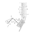
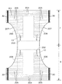
図1は、紙おむつを長手方向に展開した状態を示しているが、装着時には、紙おむつが舟形に体に装着されるので、そして各伸縮部材50,50…の収縮力が作用するので、製品の前後端はそのままで、脚周りでは図3に示すように、各伸縮部材50,50…の収縮力により起立カフスbが起立する。そしてこのとき、吸収主体10の側部を変形させ持ち上げ、また若干吸収体ABも変形させつつ持ち上げ、深いポケット空間を形成する。
【0038】
しかも、この持ち上げ状態で、各伸縮部材50,50…の収縮力が起立カフスb自体に作用するから、起立部b1はほぼ垂直に起立するようになる。平面当り部b2も、垂直に起立するようになるものの、平面当り部相当部b22が折り返し反転した状態で起立部相当部b11上に固定されているから、垂直に起立にも限度があり、平面当り部b2は外向き状態を保持したまま、垂直方向の起立力を維持しながら起立する。その結果、平面当り部b2は、常に、着用者の脚周りに平面的にフィットする。
【0039】
起立部b1,b1で囲まれる空間は、尿または軟便の閉じ込め空間を形成する。この空間内に排尿されると、その尿は透液性トップシート11を通って吸収体AB内に吸収されるとともに、軟便の固形分については、起立カフスbの起立部b1,b1がバリヤーとなり、その乗り越えが防止される。万一、起立部b1の起立遠位縁を乗り越えて横に漏れた尿は、平面当り部b2によるストップ機能により横漏れが防止される。
【0040】
さらに本例では、起立端より中心側であってかつ吸収体ABの両側部位置に、長手方向に沿う持ち上げ用伸縮部材60が伸張状態で固定されている。
【0041】
図示形態では、持ち上げ用伸縮部材60は不透液性バックシート12と吸収体ABとの間に介在されている。そして、平面視での位置としては、図2に明示されているように、脚周り部位においては吸収コア13の括れ部分と重ならず、長手方向前後においては吸収コア13の張り出し部と重なる位置にある。
【0042】
かかる持ち上げ用伸縮部材60を設けることにより、製品の装着状態において、図3に示すように、持ち上げ用伸縮部材60の収縮力(その作用状態を白抜き矢印で示す)により吸収体ABの両側部が変形し着用者の肌に向かって起立するようになる。この起立部分に対して、起立カフスbが、持ち上げ用伸縮部材60の外側の起立端を介して前記吸収体ABの両側部における起立部分に加算して起立するようになるので、肌に対する起立高さが高いものとなり、すなわち、より深いポケット空間が形成され、肌とのフィット性が高まり、単に起立カフスbのみでも横漏れを確実に防止できる。
【0043】
他方、前身頃Fと後身頃Bとにおいて、外形シート1の不織布間及び外形シート1の裏面側シートの前後端部の折り返し巻き込み部分には、胴周りのフィット性を高めるために、胴周り開口部の端縁に平行に間隔を置いて細い糸ゴムからなるウエスト伸縮部材20F,20B…が伸縮するように伸長下に配置固定されている。ウエスト伸縮部材20F,20B…の間隔および本数は適宜定めることができるが、例えば間隔としては4〜6mm程度、本数としては5〜7本程度が好ましい。
【0044】
そしてかかる構成のもと、前身頃Fの下腹部相当個所に腰周り締め付け方向(胴周り開口部の端縁と平行な方向。以下同じ。)に沿って下腹部伸縮部材21F,21Fが設けられ、かつ下腹部相当個所に対応した後身頃Bの臀部個所に腰周り締め付け方向に沿って臀部伸縮部材21Bが設けられている。そして、下腹部伸縮部材21F,21Fは、前身頃Fにおける一方側の接合部30から他方側の接合部30までの部分のうち吸収体ABの一部の部分が不連続に形成されている。一方、臀部伸縮部材21Bは、従来と同様、後身頃Bにおける一方側の接合部30から他方側の接合部30まで連続的に設けられている。また、下腹部伸縮部材21F,21Fの不連続側と反対側の側端は、臀部伸縮部材21Bの両端にそれぞれ連続するようになる。
【0045】
図示例では、これら下腹部伸縮部材21Fおよび臀部伸縮部材21Bとして、細い糸ゴムからなる伸縮部材が伸縮するように伸長下に、前身頃F及び後身頃Bの両者において、それぞれ平行に9〜25本、外形シート1の不織布間に配置固定されている。この下腹部伸縮部材21Fおよび臀部伸縮部材における相互間隔は、ウエスト伸縮部材20F,20B…の間隔に対して同じか、あるいはそれよりも短いものとされている。
【0046】
また、これら下腹部伸縮部材21Fおよび臀部伸縮部材21Bとして使用する糸ゴムは、前述のウエスト伸縮部材20F,20B…として使用する細い糸ゴムよりも伸張応力および断面外径が小さいか、あるいは実質的に同一のものとすることができる。簡易には両者において全く同じ糸ゴムを使用することで対応できるが、色分け等の上記特性以外において差別化を図っても良い。ここにおいて使用する細い糸ゴムとしては、具体的には、伸張応力が、150%伸長時において4〜17gの範囲、特に5〜10gの範囲のものが好適に使用され、断面外径が100〜350μmの範囲、特に120〜270μmの範囲のものが好適に使用される。
【0047】
かくして、前身頃Fにおける一方側の接合部30から他方側の接合部30までの部分のうち吸収体ABの一部の部分が不連続に形成されたことにより、下腹部伸縮部材21F,21Fが前身頃Fにおいて吸収体ABを横切って連続しなくなり、吸収体ABに対する腰周り締め付け方向の収縮力が弱められる。その結果、従来のように吸収体ABを横切る伸縮部材の作用によりに腰周り締め付け方向に沿って形成される縦皺により吸収体が肌から浮き上がり、腰周り部分からの漏れが生じるという問題が防止される。また本例では、臀部伸縮部材21Bは、従来と同様、後身頃Bにおける一方側の接合部30から他方側の接合部30まで連続的に形成しているので、ずれ落ち防止および肌への密着性を前述従来例と同程度に高めることができる。また前身頃Fにおける下腹部伸縮部材21F,21Fが不連続の部分に殆ど皺がなくなるため、その上から着用するパンツとの密着性も良好となり、すっきりとした見栄えのよいものとなる。なお、図示していないが、下腹部伸縮部材21F,21Fは、前身頃Fにおける一方側の接合部30から他方側の接合部30までの部分のうち吸収体ABの全部の部分を不連続に形成することもでき、この場合にも上記と同様の作用効果が奏せられる。
【0048】
他方、図5は紙おむつの他の例を示しており、吸収主体10よりも若干幅広な矩形状の本体外形シート1Aと、股間部4を除く前身頃部分を形成する前身頃胴回りシート1Bと、股間部4を除く後身頃部分を形成する後身頃胴回りシート1Cとを積層固定してなるものである。
【0049】
本体外形シート1Aには、胴周り開口部を構成する両端縁部に端縁と平行に間隔を置いて複数のウエスト伸縮部材70F,70Bがそれぞれ伸長下に配置固定されている。前身頃胴回りシート1Bの各脇部相当個所には、製品幅方向に沿って連続する多数の伸縮部材71F,71Fがそれぞれ伸張下に取り付けられており、これら脇部相当個所の伸縮部材71F,71F相互は不連続とされている。一方、後身頃胴回りシート1Cにおいては、伸縮部材71Bが、一方側の接合部から他方側の接合部まで連続的に延在するように配置固定されている。そして、これら伸縮部材のうちウエスト伸縮部材と連続する部分は、機能的にもかつ概念的にもウエスト伸縮部材の一部を構成する。
【0050】
<他の紙おむつの例>
上記例では、下腹部伸縮部材を不連続に形成し、且つ臀部伸縮部材を連続的に形成したが、反対に下腹部伸縮部材を一方側接合部から他方側接合部まで連続的に形成し、且つ臀部伸縮部材を一方側接合部から他方側接合部までの部分のうち吸収体の一部または全部の部分を不連続に形成したり、後述例のように、下腹部及び臀部の伸縮部材の両方を一方側接合部から他方側接合部までの部分のうち吸収体の一部または全部の部分を不連続に形成したりすることもできる。
【0051】
<紙おむつの製造における伸縮部材取付方法の実施形態>
次に、本発明の伸縮部材取付方法を適用した紙おむつの製造方法の実施形態について説明する。
(第1の形態;特に請求項1記載の発明に関する)
図6は、第1の形態に係るパンツタイプ紙おむつの組み立てフローを示しており、吸収主体製造供給ライン100と、外形シート製造供給製造ライン200と、最終処理ライン300とで構成されている。
【0052】
吸収主体製造供給ライン100においては、先ず吸収コアが、その長手方向が搬送方向に沿うように供給され、この上に透液性トップシートが被されて固定され、さらにこの透液性トップシートの両側端部に起立カフスがそれぞれ配置固定される。次いで、これらは、別途供給される不透液性バックシートの上に配置固定され、吸収主体10が完成する。本例の場合、不透液性バックシートは、予めその両側端部を折り返すとともにその間に色の着いたウレタンフィルム等の補強部材を挟んで接着し、当該縁部のコシを強くするように加工される(補強部材を用いずにカラーホットメルト接着により側縁部を強調させたり、コシを強くしたりしても良い)。
【0053】
かくして製造された吸収主体10は、90度ターン装置110において、その長手方向が搬送方向に対して直交する姿勢となるように平面的に90度ターンされ、最終処理ライン300の外形シート取付装置310へと搬送される。
【0054】
この一方で、外形シート製造供給製造ライン200において、製品幅方向に連続する帯状外形シート201に対して下腹部伸縮部材および臀部伸縮部材、ならびにウエスト伸縮部材の取り付けがなされる。
【0055】
詳細には帯状外形シート201が先ずスリップカッター装置210に送り込まれる。このスリップカッター装置210においては、別途供給されたデザインシート202がスリップされ供給間隔をあけられながら所定形状に順次カットされるとともに、図9にも示すように、このカットされたデザインシート202,202が帯状外形シート201の上面における前身頃幅方向中央部および後身頃幅方向中央部に対し、ホットメルト接着等によりそれぞれ配置固定される。デザインシートとしては透けない材質のフィルム等に絵柄等を付したものを用いることができる。
【0056】
次いで、このデザインシート202,202を貼り付けた外形シート201上面に対し、図9にも示すように連続するウエスト伸縮部材203,203が各身頃の所定部位にそれぞれ連続的に供給され(例えば糸ゴムや帯状ゴム等の材が複数本間隔をおいて平行に供給される)、ホットメルト接着により固定される。続いて、このウエスト伸縮部材203を取り付けた外形シート201は胴周り伸縮部材取付装置220に供給され、下腹部伸縮部材および臀部伸縮部材がそれぞれ取り付けられる。
このため本例では、図7に示すように下腹部伸縮部材帯供給ラインおよび臀部伸縮部材帯供給ライン230,230が個別に設けられている。各ライン230においては、図8に示すように複数本の連続伸縮部材(糸状、紐状、帯状等の弾性材。以下同じ。)205が連続帯状の支持シート204上に間隔をおいて平行に且つホットメルト接着等により伸張下に配置固定され、連続帯状の伸縮シート状部材206,206がそれぞれ形成され、これらが胴周り伸縮部材取付装置220にそれぞれ送給される。図示しないが、一本の連続帯状の伸縮シート状部材を形成してから、これをスリッターカッターにより長手方向に沿って切断して、複数本の連続帯状の伸縮シート状部材を形成し、これらを胴周り伸縮部材取付装置220にそれぞれ送給するようにすることもできる。
【0057】
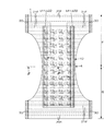
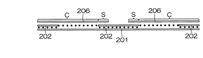
胴周り伸縮部材取付装置220においては、各帯状伸縮シート状部材206,206が所定長さに順次切り離されて伸縮シート状部材206,206…がそれぞれ形成される一方で、別途送り込まれてくる外形シート201に対し、下腹部相当個所における製品幅方向中央部を除いた部分および臀部相当個所における製品幅方向中央部を除いた部分に、図示しない接着剤塗布装置によりホットメルト接着剤HM等が間欠的にそれぞれ塗布される。そして、この外形シート201の下腹部相当個所および臀部相当個所に、伸縮シート状部材206,206…が製品幅方向となる方向に連なり且つ製品幅方向となる方向に沿う伸張下に配置される。なお、このとき伸縮シート状部材206,206…はその伸縮部材取付面が外形シート201に合わさるように配置される。かくして前述のように接着剤HMが間欠塗布されているので、図11にも示すように、各伸縮シート状部材206における他の伸縮シート状部材206との隣接端部S,Sは外形シート201と接着されずに当該隣接端部S,Sを除く中央部分C,Cが外形シート201に接着固定される。
【0058】
続いて、この外形シート201に取り付けられた伸縮シート状部材206,206…は接着固定後に伸張状態から開放され、図10のほか図12にも示すように各伸縮シート状部材206,206…における未固定隣接端部S,Sが収縮する。これによって、外形シート201に取り付けられた伸縮シート状部材206,206…相互は離間し不連続となる。
【0059】
以上の部材取付が施された外形シート201は、続いて最終処理ライン300の外形シート取付装置310へ送り込まれる。ここでは、図10のほか図13にも示すように、外形シート201の製品幅方向中央部相当部位に対し、別途送り込まれてくる吸収主体10が配置されホットメルト接着等により固定される。
【0060】
そして各種部材の取付が完了した外形シート201は、順次ダイカッター装置320に送り込まれ、そこで脚周り開口部207相当個所がくり貫かれ、次いで折り畳み装置330により、図10に示すように前身頃Fおよび後身頃Bの両側縁部30,30が重なるように2つ折りされ、続くヒートシール装置340により両側縁部30,30がヒートシールされた後、ファイナルカッター350において搬送のために残しておいた余代部分が切り落とされウエスト開口端縁相当個所が形成されるとともに、連続する製品相互がその側縁部30,30間相当個所に沿って切り離され、および製品寸法に合うようにカットされて個々のおむつPO,PO…とされる。これら個々のおむつPO,PO…は、必要に応じて転写ロール360により外形シート201表面に絵や模様等が転写された後、順次図示しない計数装置へ送給される。
【0061】
かくして製造された紙おむつPOは、図14に展開状態(表面側)で示すように、下腹部における伸縮部材205,205を含む伸縮シート状部材206,206が、前身頃Fにおける一方側の接合部30から他方側の接合部30までの部分のうち吸収体の幅方向中央部と対応する部分が不連続に(間欠的に)設けられるとともに、臀部における伸縮部材205,205を含む伸縮シート状部材206,206も、後身頃Bにおける一方側の接合部30から他方側の接合部30までの部分のうち吸収体の幅方向中央部と対応する部分が不連続に形成されたものとなる。また、各下腹部および臀部伸縮部材205,205は、吸収体がわ端部S,S…を除く主要部が伸張下に取り付けられ且つ吸収体がわ端部S,S…が非伸張下に取り付けられたものとなる。この紙おむつは、図14からも判るように下腹部伸縮部材205,205および臀部伸縮部材205,205は、それぞれ吸収体がわ端部の未接着収縮部分S,S…が吸収主体10の側端部と重なるが、この重なり部分の伸縮部材はおむつ表面側からはデザインシート202に隠れて見えないようになっている。
【0062】
なお、下腹部伸縮部材205,205および臀部伸縮部材205,205は、吸収体の幅方向全部と対応する部分を不連続にすることもできる。
【0063】
他方、図7等における臀部伸縮部材帯供給ライン230を省略し、その代わりに、前述の図8に示すのと同様に製造した伸縮シート状部材を、そのまま、外形シート製造ラインにおいて外形シートの所定部位に対して伸張下に配置しホットメルト接着剤等により固定することにより、前述図1等に示すのと同様な、臀部伸縮部材のみを後身頃の一方側側縁部から他方側側縁部まで連続的に配置固定した紙おむつとすることができる。
【0064】
また、前述の図8に示す帯状伸縮シート状部材の切断を変更し、図38に示すように、帯状伸縮シート状部材206Xを切断する代わりに、幅方向端縁部206aを残すように部分的に切り離し、この幅方向端縁部206aをウエスト伸縮部材となし、切り離し部206bを下腹部および臀部伸縮部材となすこともできる。206cは切り離し線を示している。この場合、前述の図6に示すウエスト伸縮部材の供給ラインを省略することが可能となる。
【0065】
(第2の形態;本発明に含まれない参考形態)
図15は、第2の形態に係るパンツタイプ紙おむつの組み立てフローを示しており、主ラインに対して、起立カフスが形成された吸収主体、胴周り伸縮部材、ウエスト伸縮部材、外形シートがこの順に供給され、組み立てが行われるものである。
【0066】
起立カフスが形成された吸収主体は、その長手方向を主ライン300の搬送方向に合わせるようにして、図示しない吸収主体製造ラインから主ラインに順次送り込まれる。主ライン300に送り込まれた吸収主体は、90度ターン装置301において、その長手方向が搬送方向に対して直交する姿勢となるように平面的に90度ターンされ、胴回り伸縮部材配置装置302へと搬送される。姿勢変更以降の主ラインの流れが図16および図17に示されている。
【0067】
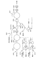
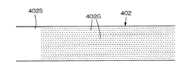
その一方で、下腹部伸縮部材帯供給ラインおよび臀部伸縮部材帯供給ライン310,310において、下腹部伸縮部材帯403および臀部伸縮部材帯404がそれぞれ製造される。すなわち各ライン310,310において、先ず図18に示すように、帯状の支持シート402Sにその長手方向に沿って連続伸縮部材402Gを伸張下に配置固定し、連続帯状の伸縮シート状部材402を形成する。特に一対の帯状不織布を張り合わせるとともにそれらの間全体に長手方向に沿って連続するように、伸縮部材を配置固定して、連続帯状の伸縮シート状部材402を形成するのが望ましい。そしてその一方で、図19に示すように不織布からなる帯状搬送シート401を連続的に供給し、塗布装置311において、この帯状搬送シート401における長手方向に所定の間隔をあけて設定された伸縮部材貼付領域の上面全体にホットメルト接着剤HMを順次塗布し、次いでダイカッター312によりこの接着剤塗布領域HMの縁部塗布領域を除く中央部に、開口401Hを順次並設する。しかる後、スリップカッター313において、別途供給された連続帯状の伸縮シート状部材をスリップさせながら所定長に順次カットするとともに、このカット伸縮シート状部材402を搬送シート401に対してその開口401Hの接着剤塗布縁部上面間に跨ってかつ開口401H全体を覆うように順次タイミングをとって非伸張下に貼り付け固定する。かくして、伸縮部材402,402が長手方向(製品幅方向となる方向)に間欠的に取り付けられた下腹部伸縮部材帯403および臀部伸縮部材帯404がそれぞれ製造される。
【0068】
次いで、これら下腹部伸縮部材帯403および臀部伸縮部材帯404は、主ライン300の胴回り伸縮部材配置装置302へ供給され、そこで図16にも示すように伸縮部材402を張付けた側を上面として搬送ラインの各側端部(下腹部相当個所および臀部相当個所)にそれぞれ配置され、その上の所定位置に前述の吸収主体10が配置され、次いでレグホールダイカッター303において、下腹部伸縮部材帯403および臀部伸縮部材帯404における所定個所が順次切り落とされ脚周り開口部RH,RHが形成された後、ウエスト伸縮部材の配置を行うスリップカッター装置304に送り込まれる。かくして、下腹部伸縮部材帯403および臀部伸縮部材帯404の各伸縮部材402,402が製品幅方向に沿って間欠的に配置されることになる。
【0069】
その一方で、ウエスト伸縮部材帯供給ライン320においては、一対のウエスト伸縮部材帯410,410が製造される。すなわち図20に示すように、先ず一対の帯状不織布405,405を張り合わせるとともに、それらの間における幅方向両側縁部406,406を除いた中央部全体に、長手方向に沿って連続する糸ゴム等の連続伸縮部材407を伸張下で複数平行に配置固定して、連続する伸縮帯状部材408を順次製造する。続いてこの帯状伸縮部材408を、スリップカッター装置304において、長手方向に沿って且つ貼付けた伸縮部材407を一方側から他方側へおよび他方側から一方側へ所定のシート長手方向間隔で交互に横切る波状カット(図示例では矩形波状)により2分割して、伸縮部材のない側縁部406とその長手方向に間隔を置いて縁部カット側に張り出す複数の伸縮部材固定張出部409,409をそれぞれ有する一対のウエスト伸縮部材帯(分割帯状部材)410,410を形成し、これらを主ラインに供給する。なおこの際、切断直後の一対のウエスト伸縮部材帯は張出部409,409の位相がずれているが、スリップカッター装置304におけるスリップ移送により、いずれか一方の分割帯状部材410の位相が調整され、張出部409,409相互の位相が合わせられた後に主ラインに供給される。
【0070】
スリップカッター装置304に送り込まれた一対の分割帯状部材410,410は、図16に示すように、その一方410が別途送り込まれてくる配置済みの下腹部伸縮部材帯403上の所定位置に前身頃側ウエスト伸縮部材として、および他方410が臀部伸縮部材帯404上の所定位置に、後身頃側ウエスト伸縮部材としてそれぞれ伸張下で配置固定される。かくして、外側シート内側に取り付ける部材の全てが所定位置に配置された状態となり、これらがそのままの状態で外側シート取付装置305へ順次送り込まれる。
【0071】
外側シート420は外側シート製造ライン330において別途製造され、取付装置305へ供給される。本例では先ず、予め所定の矩形にカットした外側シート420の製品表面がわとなる面に、スリップカッター装置331において順次カットされ供給されるデザインシート422が図21に示すように配置固定される。図示例ではデザインシート422は透けないフィルム材料で形成されるとともに表面に絵柄が付されており、外側シート420表面(上面)における吸収主体と対応する部分を覆うように配置固定されている。かかる外側シート420配置により、後に胴周り伸縮部材の製品幅方向中央部が隠され、前身頃および後身頃の両方の見栄えがすっきりとする。
【0072】
次に本例では、外側シート420の両側縁部421,421を折り返すとともに、その間に色の着いたウレタンフィルム等の補強部材423を挟んで接着し、当該縁部のコシを強くするようにしている。この補強部材を用いずにカラーホットメルト接着により側縁部421,421を強調させたり、コシを強くしたりしても良い。
【0073】
かくして製造された外側シート420が主ライン300の部材取付装置305に供給され、この部材供給装置305においてその製品幅方向となる方向が主ライン搬送方向となるようにターンされた後、その上に別途送り込まれてくる下腹部伸縮部材帯403、臀部伸縮部材帯404、吸収主体10およびウエスト伸縮部材410,410が、外側シート420上の所定位置に配置固定される(図示せず)。次に、これらは外側シート420とともに折り畳み装置306により、図16および図17の対比からも判るように前身頃Fおよび後身頃Bの両側縁部30,30が重なるように2つ折りされ、続くヒートシール装置307により両側縁部30,30がヒートシールされた後、スリッターカッター308において搬送のために残しておいた余代部分430が切り落とされウエスト開口端縁相当個所が形成され、続いて最終カッター309において連続する製品相互がその側縁部30,30間相当個所に沿って切り離され、および製品寸法に合うようにカットされて個々のおむつPO,PO…とされた後、順次図示しない計数装置へ送給される。
【0074】
かくして製造された紙おむつは、図22に展開状態(表面側)で示すように、下腹部伸縮シート状部材402,402が、前身頃Fにおける一方側の接合部30から他方側の接合部30までの部分のうち吸収体中央部と対応する部分が不連続に形成されるとともに、臀部伸縮シート状部材402,402も、後身頃Bにおける一方側の接合部30から他方側の接合部30までの部分のうち吸収体中央部と対応する部分が不連続に形成されたものとなる。また、これら下腹部および臀部の伸縮シート状部材402,402…のうちウエスト伸縮部材407,407と連続する部分は、機能的にも概念的にもウエスト伸縮部材を構成するようになる。そして本製造方法による紙おむつにおいては、各下腹部および臀部伸縮シート状部材402,402は、その周縁部に沿うコ字形枠状支持シート432,432(元は搬送シート401)とともに被取付部材に取付けられたものとなる。
【0075】
なお、下腹部および臀部伸縮シート状部材402,402…は、吸収体の幅方向全部と対応する部分を不連続にすることもできる。
【0076】
他方、本第2の形態においては、次記(イ)〜(ハ)のような変形も可能である。
(イ)上記例において、ウエスト伸縮部材帯供給ライン320の間欠取付機構は、下腹部伸縮部材帯供給ラインおよび臀部伸縮部材帯供給ライン310,310の間欠取付機構に適用することができる。さらにこれとともに又は別に、下腹部伸縮部材帯供給ラインおよび臀部伸縮部材帯供給ライン310,310の間欠取付機構をウエスト伸縮部材帯供給ライン320の間欠取付機構に適用したり、いずれか一方のラインに公知の伸縮部材取り付け方法を採用することもできる。
【0077】
(ロ)臀部伸縮部材帯供給ライン310のみを変更し、長手方向に連続する伸縮部材を有する臀部伸縮部材帯を製造供給するように構成する。具体的には前述の図18に示した連続帯状の伸縮シート状部材402を製造し、これをそのまま前述の主ライン300の胴回り伸縮部材配置装置302へ供給するように構成することにより、図5に示すのと同様な、臀部伸縮部材のみを後身頃の一方側側縁部から他方側側縁部まで連続的に配置固定した紙おむつを製造することができる。
【0078】
(ハ)他方、上述の取付方法例では、下腹部伸縮部材帯供給ラインおよび臀部伸縮部材帯供給ラインを別個に設けたが、例えば図23に示すように下腹部伸縮部材帯および臀部伸縮部材帯供給ラインを1ラインとし、そこで図24に示すように幅広な伸縮部材帯510を製造し、これを幅方向中心線Lに沿って切り離して2分割し、一方を下腹部伸縮部材帯513としておよび他方を臀部伸縮部材帯514として前述の主ライン300の胴回り伸縮部材配置装置302へ供給し、各位置に配置するように構成することができる。
【0079】
(第3の形態;特に請求項2、3記載の発明に関する)
図25は、第3の形態に係るパンツタイプ紙おむつの組み立てフローを示しており、吸収主体製造供給ライン600と、外形シート製造供給製造ライン700と、最終処理ライン800とで構成されている。
【0080】
吸収主体製造供給ライン600においては、先ず吸収コアが、その長手方向が搬送方向に沿うように供給され、この上に透液性トップシートが被されて固定され、さらにこの透液性トップシートの両側端部に起立カフスがそれぞれ配置固定される。次いで、これらは、別途供給される不透液性バックシートの上に配置固定され、吸収主体10が完成する。本例の場合、不透液性バックシートは、予めその両側端部を折り返すとともにその間に色の着いたウレタンフィルム等の補強部材を挟んで接着し、当該縁部のコシを強くするように加工される(補強部材を用いずにカラーホットメルト接着により側縁部を強調させたり、コシを強くしたりしても良い)。
【0081】
かくして製造された吸収主体10は、90度ターン装置610において、その長手方向が搬送方向に対して直交する姿勢となるように平面的に90度ターンされ、最終処理ライン800の外形シート取付装置801へと搬送される。
【0082】
この一方で、外形シート製造供給製造ライン700において、製品幅方向に連続する帯状の外形シート701に対して下腹部伸縮部材および臀部伸縮部材、ならびにウエスト伸縮部材の取り付けがなされる。
【0083】
詳細には帯状外形シート701が先ずスリップカッター装置710に送り込まれる。このスリップカッター装置710においては、別途供給されたデザインシート702がスリップされながら所定形状に順次カットされるとともに、図28にも示すように、このカットされたデザインシート702,702が帯状外形シート701の上面における前身頃幅方向中央部および後身頃幅方向中央部に対し、ホットメルト接着等によりそれぞれ配置固定される。デザインシート702としては透けない材質のフィルム等に絵柄等を付したものを用いることができる。
【0084】
次にこのデザインシート702,702を貼り付けた外形シート701は、胴周り伸縮部材取付用スリップカッター720に供給され、下腹部伸縮部材および臀部伸縮部材がそれぞれ取り付けられる。
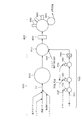
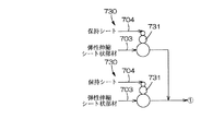
このため本例では、図26に示すように、下腹部伸縮部材帯供給ラインおよび臀部伸縮部材帯供給ライン730,730を個別に設けており、各ライン730では、図27に示すように帯状の支持シート703Sにその長手方向に沿って複数の糸ゴム等の連続伸縮部材703Gを伸張下に配置固定した連続帯状の伸縮シート状部材703がスリップカッター装置731に供給される。なお、ここで用いる一対の連続帯状の伸縮シート状部材703,703としては、個別のラインで製造しても良いが、一本の連続帯状の伸縮シート状部材を形成してから、これをスリッターカッターにより長手方向に沿って複数本に切断して形成することもできる。
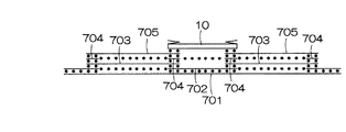
【0085】
その一方で、スリップカッター装置731に対して、帯状伸縮シート状部材703よりも幅広な連続帯状保持シート704が別途供給され、この連続帯状保持シート704がスリップされながら所定長に順次カットされる。保持シート704としては外形シートや伸縮部材に対する接着性が良好なフィルムや不織布を用いることができる。そしてカットされた保持シート704は図30に示すように帯状伸縮シート状部材703上面に対しその連続方向に所定間隔をおいて配置され、ホットメルト接着等により固定される。
【0086】
かくして製造された保持シート付帯状伸縮シート状部材703が胴周り伸縮部材取付用スリップカッター720に対して移送される。胴周り伸縮部材取付用スリップカッター720においては、保持シート付帯状伸縮シート状部材703がスリップされながら保持シート中央線(帯状伸縮シート状部材703の幅方向に沿う中央線)に沿って順次切断され、この切断された保持シート付伸縮シート状部材703,703…は、相互に別体とされた一対の保持シート704,704(保持部材)が製品幅方向両端部に固定されるとともに、各保持シート704,704が各伸縮シート状部材703の脇にはみ出したものとなっており、図28に示すように製品幅方向に伸張されつつ且つ図31にも示すように保持シート704のはみ出し部S,Sも含めて接着剤により、順次送り込まれてくるデザインシート付外形シート701の上面に対して順次固定される。またこの固定状態の製品幅方向に沿う縦断面が図32に示されている。
【0087】
かくして、伸縮シート状部材703は、それ自体伸縮しない保持シートS,Sを介して外形シート701に対して接着され、また伸縮シート状部材703自体も外形シート701に対する接着面積が広くなるため、伸張した伸縮シート状部材703がその収縮力に抗して伸張下に保持された状態で外形シート701に対して接着される。よって、このように伸縮シート状部材703を不連続(間欠)的に取付る場合であっても、伸張下に外形シート701に対し取り付けることが可能となる。
【0088】
次に、伸縮シート状部材703を取り付けた外形シート701は、押えシート取付用スリップカッター装置740に供給される。このスリップカッター装置740においては、別途連続帯状の押えシート705が供給され、これがスリップされながら所定形状に順次カットされ、図28のほか図33にも示すようにこれらカットされた押えシート705,705が、順次送り込まれてくる外形シート701上面に間欠的に取り付けられた各保持シート付伸縮シート状部材703の上面全体に、順次被せられホットメルト接着剤等によりそれぞれ接着される。
【0089】
次いでこの外形シート701は、順次ダイカッター装置750に送り込まれ、そこで脚周り開口部相当個所がくり貫かれる。図28ではこのくりぬき個所を706として示した。
【0090】
以上の取付および加工が施された外形シート701は、続いて最終処理ライン800の外形シート取付装置810へ送り込まれる。ここでは、先ず順次送り込まれてくる外形シート701上面に対し、図29に示すように複数本の連続伸縮部材707が間隔をおいて平行にウエスト開口縁部に供給され、ホットメルト接着により固定される。続いて、図28のほか図34にも示すように、外形シート701の製品幅方向中央部相当部位に対し、別途送り込まれてくる吸収主体10が配置されホットメルト接着により固定される。
【0091】
かくして各種部材の取付が完了した外形シート701は、次に折り畳み装置820により、図29に示すように前身頃Fおよび後身頃Bの両側縁部30,30が重なるように2つ折りされ、続くヒートシール装置830により両側縁部30,30がヒートシールされた後、ファイナルカッター840において搬送のために残しておいた余代部分が切り落とされウエスト開口端縁相当個所が形成されるとともに、連続する製品相互がその側縁部30,30間相当個所に沿って切り離され、および製品寸法に合うようにカットされて個々のおむつPO,PO…とされる。これら個々のおむつPO,PO…は、必要に応じて転写ロール850により外形シート201表面に絵や模様等が転写された後、順次図示しない計数装置へ送給される。
【0092】
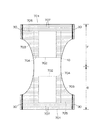
かくして製造された紙おむつは、図35に展開状態(表面側)で示すように、下腹部伸縮シート状部材703,703が、前身頃Fにおける一方側の接合部30から他方側の接合部30までの部分のうち吸収体中央部と対応する部分が不連続に形成されるとともに、臀部伸縮シート状部材703,703も、後身頃Bにおける一方側の接合部30から他方側の接合部30までの部分のうち吸収体中央部と対応する部分が不連続に形成されたものとなる。そしてこの紙おむつにおいては、各下腹部および臀部伸縮シート状部材703,703は、不連続がわ端部に、保持シート片704,704がそれぞれ積層固定されたものとなる。また、各見頃における保持シート片704,704は相互に独立したものとなる。またこの紙おむつでは、下腹部および臀部伸縮シート状部材703,703…の吸収体がわ端部が吸収主体10の側端部と重なるようになっているが、この重なり部分の伸縮部材はおむつ表面側からはデザインシートに隠れて見えないようになっている。
【0093】
なお、下腹部および臀部伸縮シート状部材703,703…は、吸収体の幅方向全部と対応する部分を不連続にすることもできる。
【0094】
他方、本第3の形態においては次のような変形も可能である。
(い)上記取付形態においては、押えシートを保持シート付伸縮部材に対応して間欠的に貼り付けるように構成したためスリップカッター装置が必要であったが、図36に示すようにスリップカッター装置を省き、図37に示すように連続帯状の押えシート705Xをそのまま、保持シート付伸縮部材取り付け部位に沿って連続的に貼り付けることもできる。
【0095】
(ろ)図7等における臀部伸縮部材帯供給ライン230を省略し、その代わりに、図示しないが従来と同様に外形シート201の所定部位に対して直接に、連続する糸ゴム等の伸縮部材を伸張下に且つ製品幅方向に沿って配置しホットメルト接着剤等により固定するように構成することにより、図1に示すのと同様な、臀部伸縮部材のみを後身頃Bの一方側側縁部30から他方側側縁部30まで連続的に配置固定した紙おむつとすることができる。
【0096】
【発明の効果】
以上のとおり、本発明によれば、吸収性能を阻害するような収縮が吸収体に生じないようになるとともに、見栄えがすっきりとし、なおかつ製品のずれ落ち防止および肌への密着効果が高い紙おむつを製造するのに好適な伸縮部材の取付け方法が提供される。
【図面の簡単な説明】
【図1】 パンツ型使い捨て紙おむつの展開状態平面図である。
【図2】 図1の2−2線矢視図である。
【図3】 製品状態の図1の2−2線断面相当部である。
【図4】 表面側展開状態平面図である。
【図5】 他の例の展開状態(表側)を示す平面図である。
【図6】 第1の形態に係る伸縮部材取付方法を採用した、おむつ製造ラインのフロー図である。
【図7】 下腹部伸縮部材帯供給ラインおよび臀部伸縮部材帯供給ラインを示すフロー図である。
【図8】 第1の形態に係る、伸縮シート状部材の製造工程を示す平面図である。
【図9】 第1の形態に係る、胴周り伸縮部材製造ラインの製造工程を示す平面図である。
【図10】 第1の形態に係る、最終処理ラインの製造工程を示す平面図である。
【図11】 第1の形態に係る、伸縮シート状部材の取付後収縮前状態を示す縦断面図である。
【図12】 第1の形態に係る、伸縮シート状部材の収縮後状態を示す縦断面図である。
【図13】 第1の形態に係る、吸収主体取付状態を示す縦断面図である。
【図14】 第1の形態により製造される紙おむつの展開状態(表側)を示す平面図である。
【図15】 第2の形態に係る、おむつ製造ラインのフロー図である。
【図16】 第2の形態に係る、主ラインの状態を示す平面図である。
【図17】 第2の形態に係る、主ラインの状態を示す平面図である。
【図18】 第2の形態に係る 伸縮シート状部材の製造工程を示す平面図である。
【図19】 第2の形態に係る、下腹部および臀部伸縮部材帯の製造工程を示す平面図である。
【図20】 第2の形態に係る、ウエスト伸縮部材の製造工程を示す平面図である。
【図21】 第2の形態に係る、外側シートの製造工程を示す平面図である。
【図22】 第2の形態により製造されるパンツ型使い捨て紙おむつの展開状態平面図である。
【図23】 第2の形態に係る、変形例のフロー図である。
【図24】 第2の形態に係る、変形例の下腹部および臀部伸縮部材帯の製造工程を示す平面図である。
【図25】 第3の形態に係る伸縮部材取付方法を採用した、おむつ製造ラインのフロー図である。
【図26】 下腹部伸縮部材帯供給ラインおよび臀部伸縮部材帯供給ラインを示すフロー図である。
【図27】 第3の形態に係る、伸縮シート状部材の製造工程を示す平面図である。
【図28】 第3の形態に係る、胴周り伸縮部材製造ラインの製造工程を示す平面図である。
【図29】 第3の形態に係る、最終処理ラインの状態変化を示す平面図である。
【図30】 第3の形態に係る、保持シート取付工程を示す平面図である。
【図31】 第3の形態に係る、保持シート付伸縮シート状部材の取付状態を示す縦断面図である。
【図32】 他の方向からみた、保持シート付伸縮シート状部材の取付状態を示す縦断面図である。
【図33】 第3の形態に係る、押えシート取付状態を示す縦断面図である。
【図34】 第3の形態に係る、吸収主体取付状態を示す縦断面図である。
【図35】 第3の形態により製造される紙おむつの展開状態(内側)を示す平面図である。
【図36】 第3の形態の変形例のフロー図である。
【図37】 第3の形態の変形例における押えシート取付状態を示す縦断面図である。
【図38】 第1の形態の変形例を示す平面図である。
【符号の説明】
1…外形シート、10…吸収主体、11…透液性トップシート、12…不透液性バックシート、13…吸収コア、14…クレープ紙、20F,20B…ウエスト伸縮部材、21F…下腹部伸縮部材、21B…臀部伸縮部材、40…起立用シート、50…伸縮部材、60…持ち上げ用伸縮部材、AB…吸収体、b…起立カフス。[0001]
BACKGROUND OF THE INVENTION
The present invention is a disposable paper diaper such as a pants type.HornThe present invention relates to a method for attaching an elastic member suitable for manufacturing.
[0002]
[Prior art]
The pants-type paper diaper has a liquid-permeable top sheet on the inner side of an outer sheet in which the left and right side edges on the ventral side and the left and right side edges on the back side are joined to form a pair of left and right leg openings and waist openings. A flexible absorbent body having an absorbent core sandwiched between a liquid-impermeable back sheet and attached from the front body to the back body at the center in the width direction of the outer sheet is widely used.
[0003]
In this type of pants-type disposable paper diaper, generally, in the waist region where there is no absorbent core in the vicinity of the waist circumference opening edge on the ventral side and the back side, a plurality of thread rubbers are spaced in parallel to the opening edge. A waist elastic member is provided. Furthermore, in the region around the waist up to the crotch region where the absorbent core is present and connects the pair of leg openings, it extends left and right across the absorbent core and is spaced parallel to the edges of the openings. A product having a waist elastic member made of thread rubber fixed thereto is also commercially available. The waist elastic member, together with the waist elastic member, prevents the product from slipping off, and has a function of improving the adhesion to the skin itself.
[0004]
In particular, in a pants-type paper diaper, such a waist elastic member is one attached continuously from the one side edge to the other side edge along the waist tightening direction at a position corresponding to the lower abdomen of the front body. A plurality of lower abdomen elastic members and one attached continuously from the one side edge to the other side edge along the waist fastening direction in the hip part of the back body corresponding to the lower abdomen equivalent part or It is comprised with the several collar part expansion-contraction member.
[0005]
In addition, as a manufacturing method of such a continuous lower abdomen elastic member and buttocks elastic member, there is one proposed by the present applicant in Japanese Patent Laid-Open No. 11-332913.
[0006]
On the other hand, the so-called tape-type paper diaper of the type that joins the left and right side edges on the abdomen side and the left and right side edges on the back side when using (wearing) the diaper is the mainstream that is not provided with a waist elastic member ing.
[0007]
[Problems to be solved by the invention]
However, the conventional attachment configuration of the waist elastic member is considered to improve fit and increase the front-rear leakage prevention effect in that the gap between the absorbent main body and the body is reduced. Is extended to the left and right across the absorber, so that the absorbent main body is formed with a vertical wall along the longitudinal direction of the product, and the vertical wall becomes a passage before the excretion liquid such as urine is absorbed. It has been found that it may be guided to the waist and promote front-rear leakage. In particular, infants are often on all fours, and since the direction of excretion of urine is on the front side of the product, the induction and leakage of excrement up to the waist is particularly noticeable on the front body side.
[0008]
In addition, since the conventional waist elastic members extend continuously along the waist direction in each of the front body and the back body, a large number of wrinkles are formed on the entire waist, and the appearance is clean. It was not.
[0009]
In order to solve these problems, it is simplest and most effective not to provide a waist-stretching member. However, this prevents the effect of preventing the product from slipping off and the effect of adhering to the skin.
[0010]
Therefore, the main problem of the present invention is to prevent shrinkage that inhibits absorption performance from occurring in the absorbent body, and to make the appearance clear, and to prevent the product from falling off and to have a high adhesion effect to the skin. MuOneAn object of the present invention is to provide a manufacturing method that enables manufacturing.
[0011]
[Means for Solving the Problems]
[0012]
[0013]
[0014]
[0015]
[0016]
As described in the section of the prior art, as a method for attaching the continuous lower abdomen elastic member and the heel elastic member, for example, as shown in the above-mentioned JP-A-11-332913 by the present applicants, A method is known in which a stretchable member made of a material such as rubber is continuously supplied to a member to be attached such as an outer sheet and is fixed while being stretched.
[0017]
On the contrary, DoubleWhen a plurality of elastic members are discontinuously attached at predetermined intervals in the product width direction, continuous attachment of the elastic members cannot be supported, and it is required to attach the elastic members to the attached member intermittently. In this case (especially when the attached member cannot be cut after attaching the elastic member such as an outer sheet), it is necessary to cut the elastic member to a predetermined length prior to attachment.
[0018]
However, even if the cut elastic member is attached to the attached member with an adhesive as it is, the force to hold the extension of the elastic member after attachment is only the adhesive force, unlike the case of continuous attachment. There is a problem that the expansion and contraction member directly contracts and returns to its original state due to the weak adhesive force due to the small contact area and the adhesion between different materials.
[0019]
BookThe present invention is intended to solve such problems and has the following configuration.
[0020]
<Claim1Invention of description>
To the belt-like support sheet,Multiple yarns, strings or strips continuousTelescopic member, Along the longitudinal direction at intervalsFixed placementBy,A continuous belt-like stretchable sheet-like member is formed, and this continuous belt-like stretchable sheet-like member isWhile cutting at predetermined intervals in the longitudinal direction to form a plurality of stretchable sheet members,
In a state where each stretchable sheet-like member is connected in a direction that is the product width direction and is stretched along the direction that is the product width direction, the portion excluding the adjacent end portion between each stretchable sheet-like member is the lower abdomen of the paper diaper and After adhering and fixing to the attached member constituting at least one of the flanges, the non-adjacent adjacent end portion is contracted to separate the stretchable sheet-like members from each other.DiscontinuityHarmonize,
A method for attaching an elastic member in the manufacture of a disposable diaper.
[0021]
[0022]
[0023]
[0024]
<Claim2Invention of description>
To the belt-like support sheet,Multiple yarns, strings or strips continuousTelescopic member, Along the longitudinal direction at intervalsFixed placementBy,Form a continuous belt-like stretchable sheet-like member,
In this continuous belt-like stretchable sheet-like memberAt a predetermined interval in the longitudinal direction,Made of non-woven fabric or filmRetentionSheetFixedBy forming a belt-like stretchable sheet-like member with a holding sheetAnd
This belt-shaped elastic sheet member with a holding sheetRetentionAlong the center line of the product width direction of the sheetCut offBy forming a stretchable sheet-like member with a holding sheet,
With this stretchable sheet-like member with holding sheet extended in the product width direction, it is attached discontinuously at a predetermined interval in the product width direction to the attached member constituting at least one of the lower abdomen and the heel of the paper diaper, At the time of this attachment, the elastic sheet member with the holding sheet is adhesively fixed to the attached member via the holding sheets at both ends in the product width direction.
It is characterized byA method for attaching an elastic member in the manufacture of a disposable diaper.
<Claim3Invention of description>
In fixing the holding sheet to the continuous belt-like stretchable sheet-like member, fix a holding sheet wider than the continuous belt-like stretchable sheet-like member,
3. When attaching the elastic sheet member with holding sheet to the attached member, the holding sheet is adhesively fixed to the attached member including a protruding portion from the elastic sheet member with holding sheet. The elastic member attachment method in the manufacture of paper diapers.
[0025]
<Action>
As described above, in the present invention, the stretchable sheet-like member in which the stretchable member is arranged and fixed to the support sheet is discontinuously attached to the mounted member at a predetermined interval in the product width direction. Therefore, when the expansion member is attached to the support sheet, continuous attachment is possible, and since the expansion member attached to the attached member has a sheet shape, the contact area with respect to the attached member is remarkably increased, and the adhesive force is also increased. To increase. Therefore, it becomes possible to more reliably and easily attach the plurality of elastic members to the attachment member discontinuously along the extension direction and under extension.
[0026]
DETAILED DESCRIPTION OF THE INVENTION
Hereinafter, embodiments of the present invention will be described in detail with reference to an example of a pants-type disposable diaper. The present invention joins the left and right side edges on the abdominal side and the left and right side edges on the back side when the diaper is used (when worn). The present invention can also be applied to a so-called tape type paper diaper.
[0027]
<Paper diapersExample>
PaAs shown in FIG. 1, the disposable disposable diaper includes a flexible
[0028]
The
[0029]
As shown in FIG. 2, the absorbent
[0030]
The absorbent
[0031]
Standing leg cuffs b, b projecting toward the use surface are formed on both sides of the absorbent
[0032]
In more detail, the standing cuff b is formed by doubling the standing
[0033]
The inner surface of the
[0034]
The inside from the standing end is a free part that is not fixed to the product body, and is functionally and conceptually a standing part b1 that faces the center side of the product, and a flat contact part b2 that turns back halfway and faces outward. Are classified.
[0035]
On the other hand, at the front and rear end portions in the longitudinal direction, the upright portion equivalent portion (extension portion of the upright portion b1) b11 is directed to the article in a state toward the center side of the article, specifically, liquid-permeable, by hot melt adhesive or the like. It is fixed to the outer surface of the
[0036]
In addition, the
[0037]
FIG. 1 shows a state in which the paper diaper is expanded in the longitudinal direction. At the time of wearing, the paper diaper is attached to the body in a boat shape, and the contraction force of each of the
[0038]
In addition, in this lifted state, the contraction force of each of the
[0039]
The space surrounded by the standing portions b1 and b1 forms a confined space for urine or soft stool. When urinating into this space, the urine is absorbed into the absorbent body AB through the liquid-
[0040]
Furthermore, in this example, the lifting
[0041]
In the illustrated embodiment, the lifting
[0042]
By providing such a lifting
[0043]
On the other hand, in the front body F and the back body B, a waistline opening is provided between the nonwoven fabrics of the
[0044]
And under such a configuration,in frontLower body abdominal
[0045]
In the illustrated example, the lower abdomen
[0046]
Further, the thread rubber used as the lower abdomen
[0047]
Thus, the lower abdomen
[0048]
On the other hand, FIG.PaperOther diapersExampleA rectangular main body
[0049]
In the main body
[0050]
<Other paper diapersExample>
In the above example, the lower abdomen elastic member was discontinuously formed, and the buttocks elastic member was continuously formed.On the contrary, the lower abdominal elastic member was continuously formed from the one side joint to the other side joint, In addition, a part or all of the absorbent body is formed discontinuously among the parts from the one side joint part to the other side joint part of the buttocks stretchable member, or the lower abdomen and the buttocks stretchable member as in the example described later It is also possible to discontinuously form part or all of the absorber in the part from the one side joint part to the other side joint part.
[0051]
<Embodiment of the elastic member attachment method in manufacture of a paper diaper>
Next, an embodiment of a method for manufacturing a disposable diaper to which the elastic member attaching method of the present invention is applied will be described.
(First form; in particular, claims)1(Related to the described invention)
FIG. 6 shows an assembly flow of the pant-type paper diaper according to the first embodiment, which is composed of an absorbent main body production /
[0052]
In the absorbent main body
[0053]
The absorbent
[0054]
On the other hand, in the outer sheet manufacturing
[0055]
Specifically, the belt-shaped
[0056]
Next, as shown in FIG. 9, continuous waist
For this reason, in this example, as shown in FIG. 7, the lower abdomen elastic member belt supply line and the buttocks elastic member
[0057]
In the waist elastic
[0058]
Subsequently, the stretchable sheet-
[0059]
The
[0060]
Then, the
[0061]
In the diaper PO manufactured in this way, the stretchable sheet-
[0062]
In addition,underThe abdominal
[0063]
On the other hand, the elongate elastic member
[0064]
Further, the cutting of the belt-like stretchable sheet-like member shown in FIG. 8 is changed, and instead of cutting the belt-like stretchable sheet-
[0065]
(Second form;Reference forms not included in the present invention)
FIG. 15 shows an assembly flow of the pants-type paper diaper according to the second embodiment. The main absorbent body, the waist elastic member, the waist elastic member, and the outer sheet in which the standing cuffs are formed are arranged in this order with respect to the main line. Supplied and assembled.
[0066]
The absorbent main body on which the standing cuffs are formed is sequentially sent from an absorbent main body production line (not shown) to the main line so that the longitudinal direction of the main absorbent body is aligned with the conveying direction of the
[0067]
On the other hand, in the lower abdomen elastic member band supply line and the buttocks elastic member
[0068]
Next, the lower abdomen
[0069]
On the other hand, in the waist elastic member
[0070]
As shown in FIG. 16, the pair of divided belt-
[0071]
The
[0072]
Next, in this example, the side edges 421 and 421 of the
[0073]
The
[0074]
In the paper diaper thus manufactured, as shown in the unfolded state (surface side) in FIG. 22, the lower abdomen stretchable sheet-
[0075]
In addition,underThe abdomen and buttocks stretchable sheet-
[0076]
On the other hand, in the second embodiment, the following modifications (a) to (c) are possible.
(A) In the above example, the intermittent attachment mechanism of the waist elastic member
[0077]
(B) Only the buttocks expansion / contraction member
[0078]
(C) On the other hand, in the above mounting method example, the lower abdomen elastic member band supply line and the buttocks elastic member band supply line are provided separately. For example, as shown in FIG. As shown in FIG. 24, the supply line is set as one line, and as shown in FIG. 24, a wide
[0079]
(Third embodiment; particularly related to the inventions of
FIG. 25 shows an assembly flow of the pant-type paper diaper according to the third embodiment, which is composed of an absorbent main body production /
[0080]
In the absorbent main body
[0081]
The absorbent
[0082]
On the other hand, in the outer sheet manufacturing and
[0083]
Specifically, the belt-shaped
[0084]
Next, the
For this reason, in this example, as shown in FIG. 26, the lower abdomen elastic member belt supply line and the buttocks elastic member
[0085]
On the other hand, a continuous belt-
[0086]
The belt-like
[0087]
Thus, the stretchable sheet-
[0088]
Next, the
[0089]
Next, the
[0090]
The
[0091]
The
[0092]
As shown in FIG. 35 in the unfolded state (front side), the lower diaper stretchable sheet-
[0093]
In addition,underThe abdomen and buttocks stretchable sheet-
[0094]
On the other hand, in the third embodiment, the following modifications are possible.
(Ii) In the above attachment form, since the presser sheet is configured to be affixed intermittently corresponding to the elastic member with the holding sheet, a slip cutter device is necessary. However, as shown in FIG. As shown in FIG. 37, the continuous belt-
[0095]
(B) The buttocks elastic member
[0096]
【The invention's effect】
As described above, according to the present invention, there is no shrinkage that impedes the absorption performance in the absorbent body, the appearance is clean, the product is prevented from falling off, and the effect of close contact with the skin is high. MuOneA method for attaching a telescopic member suitable for manufacturing is provided.
[Brief description of the drawings]
[Figure 1]PaIt is an unfolded top view of a disposable disposable diaper.
FIG. 2 is a view taken along line 2-2 of FIG.
FIG. 3 is a cross-sectional equivalent part of line 2-2 in FIG. 1 in a product state.
FIG. 4 is a plan view of a surface side unfolded state.
FIG. 5 is a plan view showing a developed state (front side) of another example.
FIG. 6Form ofIt is a flowchart of a diaper manufacturing line which employ | adopted the expansion-contraction member attachment method which concerns on a state.
FIG. 7 is a flowchart showing a lower abdomen elastic member band supply line and a buttocks elastic member band supply line.
FIG. 8Form ofIt is a top view which shows the manufacturing process of the expansion-contraction sheet-like member based on a state.
FIG. 9Form ofIt is a top view which shows the manufacturing process of the trunk periphery expansion-contraction member manufacturing line based on a state.
FIG. 10Form ofIt is a top view which shows the manufacturing process of the final processing line based on a state.
FIG. 11Form ofIt is a longitudinal cross-sectional view which shows the state before the shrinkage | contraction after attachment of the expansion-contraction sheet-like member based on a state.
FIG. 12Form ofIt is a longitudinal cross-sectional view which shows the state after shrinkage | contraction of the elastic sheet-like member based on a state.
FIG. 13Form ofIt is a longitudinal cross-sectional view which shows the absorption main body attachment state based on a state.
FIG. 14 FirstForm ofIt is a top view which shows the expansion | deployment state (front side) of the paper diaper manufactured by a state.
FIG. 15Form ofIt is a flowchart of the diaper manufacturing line based on a state.
FIG. 16Form ofIt is a top view which shows the state of the main line based on a state.
FIG. 17Form ofIt is a top view which shows the state of the main line based on a state.
FIG. 18Form ofIt is a top view which shows the manufacturing process of the elastic sheet-like member which concerns on a state.
FIG. 19Form ofIt is a top view which shows the manufacturing process of the lower abdominal part and the buttocks expansion-contraction member band based on a state.
FIG. 20Form ofIt is a top view which shows the manufacturing process of the waist elastic member based on a state.
FIG. 21Form ofIt is a top view which shows the manufacturing process of the outer side sheet based on a state.
FIG. 22Form ofIt is an expanded state top view of the underpants type disposable paper diaper manufactured by a state.
FIG. 23Form ofIt is a flowchart of the modification which concerns on a condition.
FIG. 24Form ofIt is a top view which shows the manufacturing process of the lower abdominal part and the buttocks expansion-contraction member band of the modification which concerns on a condition.
FIG. 25Form ofIt is a flowchart of a diaper manufacturing line which employ | adopted the expansion-contraction member attachment method which concerns on a state.
FIG. 26 is a flowchart showing a lower abdominal elastic member band supply line and a buttocks elastic member band supply line.
FIG. 27Form ofIt is a top view which shows the manufacturing process of the expansion-contraction sheet-like member based on a state.
FIG. 28Form ofIt is a top view which shows the manufacturing process of the trunk periphery expansion-contraction member manufacturing line based on a state.
FIG. 29Form ofIt is a top view which shows the state change of the last process line based on a state.
FIG. 30Form ofIt is a top view which shows the holding sheet attachment process based on a state.
FIG. 31Form ofIt is a longitudinal cross-sectional view which shows the attachment state of the expansion-contraction sheet-like member with a holding sheet based on a state.
FIG. 32 is a longitudinal sectional view showing an attached state of the stretchable sheet-like member with the holding sheet as seen from the other direction.
FIG. 33Form ofIt is a longitudinal cross-sectional view which shows the presser sheet attachment state based on a state.
FIG. 34Form ofIt is a longitudinal cross-sectional view which shows the absorption main body attachment state based on a state.
FIG. 35Form ofIt is a top view which shows the expansion | deployment state (inside) of the paper diaper manufactured by a state.
FIG. 36Form ofIt is a flowchart of the modification of a state.
FIG. 37Form ofIt is a longitudinal cross-sectional view which shows the presser sheet attachment state in the modification of a state.
FIG. 38: FirstForm ofIt is a top view which shows the modification of a state.
[Explanation of symbols]
DESCRIPTION OF
Claims (3)
各伸縮シート状部材を、製品幅方向となる方向に連なり且つ製品幅方向となる方向に沿って伸張した状態で、各伸縮シート状部材間の隣接端部を除く部分を、紙おむつの下腹部及び臀部の少なくとも一方を構成する被取付部材に接着固定した後、この未接着の隣接端部を収縮させて、前記伸縮シート状部材相互を離間させ不連続とならしめる、
ことを特徴とする、紙おむつの製造における伸縮部材取付方法。A continuous belt-like stretchable sheet-like member is formed by arranging and fixing a plurality of thread-like, string-like or belt-like continuous stretchable members along the longitudinal direction at intervals in a belt-like support sheet. Cutting the stretchable sheet-like member at a predetermined interval in the longitudinal direction to form a plurality of stretchable sheet-like members,
In a state where each stretchable sheet-like member is connected in a direction that is the product width direction and is stretched along the direction that is the product width direction, the portion excluding the adjacent end portion between each stretchable sheet-like member is the lower abdomen of the paper diaper and After adhering and fixing to the attached member constituting at least one of the flange parts, the unadhered adjacent end part is contracted, and the elastic sheet-like members are separated from each other to be discontinuous .
A method for attaching an elastic member in the manufacture of a disposable diaper.
この連続帯状の伸縮シート状部材における長手方向に所定の間隔をおいて、不織布又はフィルムからなる保持シートを固定することにより、保持シート付帯状伸縮シート状部材を形成し、
この保持シート付帯状伸縮シート状部材を、各保持シートの製品幅方向の中央線に沿って切断することにより、保持シート付伸縮シート状部材を形成し、
この保持シート付伸縮シート状部材を製品幅方向に伸張した状態で、紙おむつの下腹部及び臀部の少なくとも一方を構成する被取付部材に、製品幅方向に所定間隔をおいて不連続に取り付けるとともに、この取り付けに際して前記保持シート付伸縮シート状部材をその製品幅方向両端部の保持シートを介して前記被取付部材に接着固定する、
ことを特徴とする、紙おむつの製造における伸縮部材取付方法。 By forming and fixing a plurality of thread-like, string-like or belt-like continuous stretchable members along the longitudinal direction at intervals in the belt-like support sheet, a continuous belt-like stretchable sheet-like member is formed,
By fixing a holding sheet made of a nonwoven fabric or a film at a predetermined interval in the longitudinal direction of the continuous belt-like stretchable sheet-like member, a belt- like stretchable sheet-like member with a holding sheet is formed ,
By cutting the belt-like elastic sheet member with the holding sheet along the center line in the product width direction of each holding sheet, the elastic sheet member with the holding sheet is formed,
With this stretchable sheet-like member with holding sheet extended in the product width direction, it is attached discontinuously at a predetermined interval in the product width direction to the attached member constituting at least one of the lower abdomen and the heel of the paper diaper, At the time of this attachment, the elastic sheet member with the holding sheet is adhesively fixed to the attached member via the holding sheets at both ends in the product width direction.
A method for attaching an elastic member in the manufacture of a disposable diaper.
前記保持シート付伸縮シート状部材を前記被取付部材に取り付けるにあたり、前記保持シートを、前記保持シート付伸縮シート状部材からのはみ出し部を含めて前記被取付部材に接着固定する、請求項2記載の紙おむつの製造における伸縮部材取付方法。 In fixing the holding sheet to the continuous belt-like stretchable sheet-like member, fix a holding sheet wider than the continuous belt-like stretchable sheet-like member,
3. When attaching the elastic sheet member with holding sheet to the attached member, the holding sheet is adhesively fixed to the attached member including a protruding portion from the elastic sheet member with holding sheet. elastic member mounting method in the paper diaper manufacturing.
Priority Applications (5)
| Application Number | Priority Date | Filing Date | Title |
|---|---|---|---|
| JP2000218559A JP4198307B2 (en) | 2000-07-19 | 2000-07-19 | Telescopic member mounting method in the manufacture of disposable diapers |
| PCT/JP2001/006306 WO2002005738A1 (en) | 2000-07-19 | 2001-07-19 | Disposable paper diaper and method of attaching expansible members of the disposable paper diaper |
| US10/333,530 US7329245B2 (en) | 2000-07-19 | 2001-07-19 | Disposable paper diaper and method of attaching expansible members of the disposable paper diaper |
| AU2001272772A AU2001272772A1 (en) | 2000-07-19 | 2001-07-19 | Disposable paper diaper and method of attaching expansible members of the disposable paper diaper |
| KR1020037000776A KR100818719B1 (en) | 2000-07-19 | 2001-07-19 | Disposable paper diaper and method of attaching expansible members of the disposable paper diaper |
Applications Claiming Priority (1)
| Application Number | Priority Date | Filing Date | Title |
|---|---|---|---|
| JP2000218559A JP4198307B2 (en) | 2000-07-19 | 2000-07-19 | Telescopic member mounting method in the manufacture of disposable diapers |
Related Child Applications (1)
| Application Number | Title | Priority Date | Filing Date |
|---|---|---|---|
| JP2008210903A Division JP4912373B2 (en) | 2008-08-19 | 2008-08-19 | Telescopic member mounting method in the manufacture of disposable diapers |
Publications (3)
| Publication Number | Publication Date |
|---|---|
| JP2002035028A JP2002035028A (en) | 2002-02-05 |
| JP2002035028A5 JP2002035028A5 (en) | 2006-09-07 |
| JP4198307B2 true JP4198307B2 (en) | 2008-12-17 |
Family
ID=18713484
Family Applications (1)
| Application Number | Title | Priority Date | Filing Date |
|---|---|---|---|
| JP2000218559A Expired - Lifetime JP4198307B2 (en) | 2000-07-19 | 2000-07-19 | Telescopic member mounting method in the manufacture of disposable diapers |
Country Status (1)
| Country | Link |
|---|---|
| JP (1) | JP4198307B2 (en) |
Families Citing this family (3)
| Publication number | Priority date | Publication date | Assignee | Title |
|---|---|---|---|---|
| ES2765494T3 (en) * | 2005-06-09 | 2020-06-09 | Hartmann Paul Ag | Composite band, disposable diaper and manufacturing process |
| JP4989088B2 (en) * | 2006-03-27 | 2012-08-01 | 株式会社瑞光 | Method for manufacturing disposable wearing articles |
| RU2692881C1 (en) * | 2015-09-09 | 2019-06-28 | Эссити Хайджин энд Хелт АБ | Disposable absorbent panty-like article with a foot cuff |
-
2000
- 2000-07-19 JP JP2000218559A patent/JP4198307B2/en not_active Expired - Lifetime
Also Published As
| Publication number | Publication date |
|---|---|
| JP2002035028A (en) | 2002-02-05 |
Similar Documents
| Publication | Publication Date | Title |
|---|---|---|
| KR100818719B1 (en) | Disposable paper diaper and method of attaching expansible members of the disposable paper diaper | |
| RU2580990C2 (en) | Disposable diaper and method of its manufacturing | |
| KR100455828B1 (en) | Method of manufacturing absorbent product | |
| KR100591095B1 (en) | Disposable pull-on garment | |
| JP4981664B2 (en) | Wearing article and manufacturing method thereof | |
| JP5848502B2 (en) | Absorbent article and method for manufacturing absorbent article | |
| KR101605580B1 (en) | Method of manufacturing wearing article and wearing article | |
| JPH0515552A (en) | Disposable pants and manufacture thereof | |
| WO2011093152A1 (en) | Absorbent article | |
| WO2004017875A1 (en) | Disposable absorptive article | |
| TWI577356B (en) | Disposable disposable diaper and disposable disposable diaper | |
| TW201249411A (en) | Disposable diaper | |
| JP3581398B2 (en) | Disposable diapers or disposable pants | |
| JPWO2015025760A1 (en) | Disposable diaper manufacturing method and disposable diaper | |
| JP6095211B2 (en) | Pants-type absorbent article and manufacturing method thereof | |
| JP4502882B2 (en) | Disposable diaper manufacturing method | |
| JP5721987B2 (en) | Absorbent articles | |
| JP4912373B2 (en) | Telescopic member mounting method in the manufacture of disposable diapers | |
| JP4966403B2 (en) | Pants-type absorbent article | |
| JP4198307B2 (en) | Telescopic member mounting method in the manufacture of disposable diapers | |
| JP2002291799A (en) | Absorbent article | |
| TW201517887A (en) | Disposable diaper | |
| JP4082932B2 (en) | Disposable absorbent article and method for producing the same | |
| JP4163133B2 (en) | Manufacturing method of openable disposable pants | |
| TWI594740B (en) | Method of making disposable disposable diapers and disposable diapers |
Legal Events
| Date | Code | Title | Description |
|---|---|---|---|
| A621 | Written request for application examination |
Free format text: JAPANESE INTERMEDIATE CODE: A621 Effective date: 20050629 |
|
| A521 | Written amendment |
Free format text: JAPANESE INTERMEDIATE CODE: A523 Effective date: 20060720 |
|
| A131 | Notification of reasons for refusal |
Free format text: JAPANESE INTERMEDIATE CODE: A131 Effective date: 20080620 |
|
| A521 | Written amendment |
Free format text: JAPANESE INTERMEDIATE CODE: A523 Effective date: 20080819 |
|
| TRDD | Decision of grant or rejection written | ||
| A01 | Written decision to grant a patent or to grant a registration (utility model) |
Free format text: JAPANESE INTERMEDIATE CODE: A01 Effective date: 20080919 |
|
| A01 | Written decision to grant a patent or to grant a registration (utility model) |
Free format text: JAPANESE INTERMEDIATE CODE: A01 |
|
| A61 | First payment of annual fees (during grant procedure) |
Free format text: JAPANESE INTERMEDIATE CODE: A61 Effective date: 20081001 |
|
| FPAY | Renewal fee payment (event date is renewal date of database) |
Free format text: PAYMENT UNTIL: 20111010 Year of fee payment: 3 |
|
| R150 | Certificate of patent or registration of utility model |
Ref document number: 4198307 Country of ref document: JP Free format text: JAPANESE INTERMEDIATE CODE: R150 Free format text: JAPANESE INTERMEDIATE CODE: R150 |
|
| FPAY | Renewal fee payment (event date is renewal date of database) |
Free format text: PAYMENT UNTIL: 20111010 Year of fee payment: 3 |
|
| FPAY | Renewal fee payment (event date is renewal date of database) |
Free format text: PAYMENT UNTIL: 20111010 Year of fee payment: 3 |
|
| FPAY | Renewal fee payment (event date is renewal date of database) |
Free format text: PAYMENT UNTIL: 20111010 Year of fee payment: 3 |
|
| FPAY | Renewal fee payment (event date is renewal date of database) |
Free format text: PAYMENT UNTIL: 20121010 Year of fee payment: 4 |
|
| R250 | Receipt of annual fees |
Free format text: JAPANESE INTERMEDIATE CODE: R250 |
|
| FPAY | Renewal fee payment (event date is renewal date of database) |
Free format text: PAYMENT UNTIL: 20121010 Year of fee payment: 4 |
|
| FPAY | Renewal fee payment (event date is renewal date of database) |
Free format text: PAYMENT UNTIL: 20121010 Year of fee payment: 4 |
|
| FPAY | Renewal fee payment (event date is renewal date of database) |
Free format text: PAYMENT UNTIL: 20131010 Year of fee payment: 5 |
|
| R250 | Receipt of annual fees |
Free format text: JAPANESE INTERMEDIATE CODE: R250 |
|
| R250 | Receipt of annual fees |
Free format text: JAPANESE INTERMEDIATE CODE: R250 |
|
| R250 | Receipt of annual fees |
Free format text: JAPANESE INTERMEDIATE CODE: R250 |
|
| R250 | Receipt of annual fees |
Free format text: JAPANESE INTERMEDIATE CODE: R250 |
|
| R250 | Receipt of annual fees |
Free format text: JAPANESE INTERMEDIATE CODE: R250 |
|
| R250 | Receipt of annual fees |
Free format text: JAPANESE INTERMEDIATE CODE: R250 |
|
| R250 | Receipt of annual fees |
Free format text: JAPANESE INTERMEDIATE CODE: R250 |
|
| R250 | Receipt of annual fees |
Free format text: JAPANESE INTERMEDIATE CODE: R250 |
|
| EXPY | Cancellation because of completion of term |