JP4194566B2 - Fluid force cylinder - Google Patents
Fluid force cylinder Download PDFInfo
- Publication number
- JP4194566B2 JP4194566B2 JP2005021512A JP2005021512A JP4194566B2 JP 4194566 B2 JP4194566 B2 JP 4194566B2 JP 2005021512 A JP2005021512 A JP 2005021512A JP 2005021512 A JP2005021512 A JP 2005021512A JP 4194566 B2 JP4194566 B2 JP 4194566B2
- Authority
- JP
- Japan
- Prior art keywords
- fluid
- cylinder chamber
- cylinder
- fluid passage
- valve
- Prior art date
- Legal status (The legal status is an assumption and is not a legal conclusion. Google has not performed a legal analysis and makes no representation as to the accuracy of the status listed.)
- Active
Links
Images


Classifications
-
- B—PERFORMING OPERATIONS; TRANSPORTING
- B23—MACHINE TOOLS; METAL-WORKING NOT OTHERWISE PROVIDED FOR
- B23B—TURNING; BORING
- B23B31/00—Chucks; Expansion mandrels; Adaptations thereof for remote control
- B23B31/02—Chucks
- B23B31/24—Chucks characterised by features relating primarily to remote control of the gripping means
- B23B31/30—Chucks characterised by features relating primarily to remote control of the gripping means using fluid-pressure means in the chuck
-
- F—MECHANICAL ENGINEERING; LIGHTING; HEATING; WEAPONS; BLASTING
- F15—FLUID-PRESSURE ACTUATORS; HYDRAULICS OR PNEUMATICS IN GENERAL
- F15B—SYSTEMS ACTING BY MEANS OF FLUIDS IN GENERAL; FLUID-PRESSURE ACTUATORS, e.g. SERVOMOTORS; DETAILS OF FLUID-PRESSURE SYSTEMS, NOT OTHERWISE PROVIDED FOR
- F15B20/00—Safety arrangements for fluid actuator systems; Applications of safety devices in fluid actuator systems; Emergency measures for fluid actuator systems
- F15B20/007—Overload
-
- B—PERFORMING OPERATIONS; TRANSPORTING
- B23—MACHINE TOOLS; METAL-WORKING NOT OTHERWISE PROVIDED FOR
- B23B—TURNING; BORING
- B23B31/00—Chucks; Expansion mandrels; Adaptations thereof for remote control
- B23B31/02—Chucks
- B23B31/10—Chucks characterised by the retaining or gripping devices or their immediate operating means
-
- B—PERFORMING OPERATIONS; TRANSPORTING
- B23—MACHINE TOOLS; METAL-WORKING NOT OTHERWISE PROVIDED FOR
- B23B—TURNING; BORING
- B23B31/00—Chucks; Expansion mandrels; Adaptations thereof for remote control
- B23B31/02—Chucks
- B23B31/24—Chucks characterised by features relating primarily to remote control of the gripping means
- B23B31/30—Chucks characterised by features relating primarily to remote control of the gripping means using fluid-pressure means in the chuck
- B23B31/302—Hydraulic equipment, e.g. pistons, valves, rotary joints
-
- F—MECHANICAL ENGINEERING; LIGHTING; HEATING; WEAPONS; BLASTING
- F15—FLUID-PRESSURE ACTUATORS; HYDRAULICS OR PNEUMATICS IN GENERAL
- F15B—SYSTEMS ACTING BY MEANS OF FLUIDS IN GENERAL; FLUID-PRESSURE ACTUATORS, e.g. SERVOMOTORS; DETAILS OF FLUID-PRESSURE SYSTEMS, NOT OTHERWISE PROVIDED FOR
- F15B15/00—Fluid-actuated devices for displacing a member from one position to another; Gearing associated therewith
- F15B15/08—Characterised by the construction of the motor unit
- F15B15/14—Characterised by the construction of the motor unit of the straight-cylinder type
- F15B15/149—Fluid interconnections, e.g. fluid connectors, passages
Abstract
Description
本発明は、流体力シリンダに関するものであり、一層特に構造が簡単で構成がコンパクトであり、製造プロセス及びコストを経済的にできるチェックバルブを備えた流体力シリンダに関する。 The present invention relates to a fluid force cylinder, and more particularly to a fluid force cylinder having a check valve that is simple in structure and compact in configuration, and that can economically manufacture and cost.
流体力シリンダは、液体の流体エネルギを機械的運動エネルギに変換するように構成したシリンダである。一般に、流体力シリンダはシリンダ室に供給される流体の圧力によって駆動され、それにより旋盤のような機械ツールの主軸に設けられたチャックを把持したり解放できるようにする。 A fluid force cylinder is a cylinder configured to convert the fluid energy of a liquid into mechanical kinetic energy. Generally, a fluid force cylinder is driven by the pressure of a fluid supplied to a cylinder chamber, thereby enabling gripping and releasing of a chuck provided on a spindle of a mechanical tool such as a lathe.
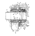
従来の流体力シリンダは、図1に示すように、
一端から他端にのびる貫通路11が形成され、外面から貫通路11の内面にのびる第1、第2流体通路12、13が設けられたシリンダ10と;
一端から他端にのびる接続部21が形成され、第1、第2流体通路12、13に連通する第3、第4流体通路23、24を備えたスリーブ部材20と;
一端が接続部21に結合されたバルブロッド31を備え、シリンダハウジング10の前方にバルブプレート32が設けられ、バルブプレート32の一側端にシリンダチャンバ33が設けられ、また第3、第4流体通路23、24をシリンダチャンバ33に接続する第5、第6流体通路34、35が設けられる回転バルブ部材30と;
前後に摺動するようにバルブロッド31に取付けたピストンロッド41及びピストンロッド41から突出してシリンダチャンバ33を前方及び後方シリンダチャンバ33a、33bに分割しかつ前方及び後方シリンダチャンバ33a、33bをピストンロッド41の周囲にシールするピストンプレート42を含む゜ピストン部材40と;
内部にシリンダチャンバ33を前方シリンダチャンバ33aに接続する第7流体通路51を一側に備えた本体部材50と;
回転パルブ部材30における第6流体通路35に設けられ、第6流体通路35及び第7流体通路51を通って前方シリンダチャンバ33aへ一定方向に流れる流体を制御する前方シリンダチャンバ70用のチェックバルブと;
回転パルブ部材30における第5流体通路34に設けられ、第5流体通路34を通って後方シリンダチャンバ33bへ一定方向に流れる流体を制御する後方シリンダチャンバ60用のチェックバルブと;
を有している。
As shown in FIG.
A
A
A
The
A
A check valve for the
A check valve for the
have.
ピストン部材40は、前方及び後方シリンダチャンバ33a、33bの一方に流体を供給し同時に前方及び後方シリンダチャンバ33a、33bの他方から流体を放出することにより前後に動く。ピストン部材40のこの往復動によって、ピストンロッド41に接続されたチャックのジョーは把持されたり解放されたりできる。
The
前方及び後方シリンダチャンバ70、60の各々は、
内部に流体通路81を備えたバルブハウジング80と;
ある一定の圧力又はそれより高い圧力の流体が供給される時に、流体通路81を閉じたり開いたりするようにばね部材83で弾性的に支持された鋼ボール82と;
バルブハウジング80の一側に設けられ、チェックバルブ60、70の各々に供給される流体の圧力によって動き、鋼ボール82を押圧し、流体通路81を開放させるパイロットスプール84と;
を備えている。
Each of the front and
A valve housing 80 with a fluid passage 81 therein;
A steel ball 82 elastically supported by a
A
It has.
従って、ある一定の圧力又はそれより高い圧力の流体が前方又は後方シリンダチャンバ70又は60のチェックバルブに供給されると、流体通路81は開放して流体をシリンダチャンバ33に供給したり、シリンダチャンバ33から流体を放出させる。
Therefore, when a fluid at a certain pressure or higher is supplied to the check valve of the front or
圧力流体の供給がマシンツールの電力供給の遮断、例えば電力の休止で止まると、鋼ボール82は、ばね部材83の復元力で最初の位置へ戻り、流体通路81を塞ぎ、それでシリンダチャンバ33内に充填された流体の放出は阻止され、そしてチャックがマシンツールから解放するのは阻止される。
When the supply of pressure fluid stops when the power supply of the machine tool is interrupted, for example, when the power is stopped, the steel ball 82 returns to the initial position by the restoring force of the
さらに、ピストン部材40のピストンプレート42は、前方又は後方シリンダチャンバ33a又は33b内に過剰圧が発生する際に、前方シリンダチャンバ33aを後方シリンダチャンバ33bに連通することにより、シリンダチャンバ33内の圧力を低減させるリリーフバルブ90を備えている。
Further, the
さらに、両端をそれぞれ本体部材50及び回転バルプ部材30に固定したガイドピン91、ピストン部材40のピストンプレート42を通して設けられ、それにより、ピストン部材40はその往復動において、前方及び後方シリンダチャンバ33a、33bを密封した状態で平滑に動くように案内される。
Further,
しかし、上記の従来の流体力シリンダでは、前方及び後方シリンダチャンバ70、60及びリリーフバルブ90は別個に接像されなければならなかった。従って流体力シリンダの全長は、チェックバルブ60、70及びリリーフバルブ90を内部に含むように長い必要があった。
However, in the above conventional fluid force cylinder, the front and
さらに、ガイドピン91は従来の流体力シリンダではピストン部材40の往復動をガイドするのに設けられなければならず、そのため製造コストを増大し、製造効率を低下させていた。
Furthermore, the
従って、流体力シリンダは構造が複雑かつ大きくなり、任意の種類のマシンツールに使用する際に構造及び大きさをコンパクトにできる限度があった。 Therefore, the fluid force cylinder has a complicated and large structure, and there is a limit to the compact structure and size when used in any kind of machine tool.
さらに、本体部材50は、前方シリンダチャンバ33aに流体を供給し又は前方シリンダチャンバ33aから流体を放出するのに、本体部材50の一側に七番目の流体通路51を設けていたので、本体部材50の一側の強度は他側より恐らく弱くなる。
Furthermore, since the
従って、本発明の目的は、製造プロセス及びコストの経済性に寄与できるコンパクトで構造の簡単な流体力シリンダを提供することにある。 Accordingly, it is an object of the present invention to provide a compact and simple hydrodynamic cylinder that can contribute to the economics of the manufacturing process and cost.
本発明の別の目的は、前方及び後方シリンダチャンバに供給される流体の流れを制御するチェックバルブ及びピストン部材の往復動をガイドするチェックバルブのバルブハウジングにおけるガイド突起部を備え、従って別個のガイドピンをもたない流体力シリンダを提供することにある。 Another object of the present invention is to provide a check valve for controlling the flow of fluid supplied to the front and rear cylinder chambers and a guide projection in the valve housing of the check valve for guiding the reciprocating movement of the piston member, and therefore separate guides. The object is to provide a fluid force cylinder without pins.
本発明のさらに別の目的は、チェックバルブのバルブハウジングに一体に設けられ、動作中に前方及び後方シリンダチャンバに発生した過剰圧力を低減させる減圧手段を備え、従って別個の減圧バルブすなわちリリーフバルブをもたない流体力シリンダを提供することにある。 Yet another object of the present invention is to provide a pressure reducing means integrally provided in the valve housing of the check valve to reduce the excess pressure generated in the front and rear cylinder chambers during operation, thus providing a separate pressure reducing valve or relief valve. The object is to provide a fluid cylinder with no fluid.
上記の目的を達成するために、本発明による流体力シリンダは、
一端から他端まで形成された貫通通路を備え、外面から貫通通路の内面にかけて第1及び第2の流体通路を備えたシリンダハウジングと;
シリンダハウジングの貫通通路に接触して固定され、一端から他端まで形成された接続部品を備え、かつ接続部品における軸受及び第1及び第2の流体通路に連通する第3及び第4の流体通路を備えたスリーブ部材と;
一端を接続部品に結合されたバルブロッド及びシリンダハウジングの前方に設けられたバルブプレートを備え、バルブプレートの一側端部にシリンダチャンバが設けられ、また、第3及び第4の流体通路をシリンダチャンバに接続するように形成した第5及び第6の流体通路を備えた回転バルブ部材と;
ピストンプレートを前後に摺動可能に動かすようにバルブロッドに固定したピストンロッドを備え、ピストンプレートがピストンロッドから突出してシリンダチャンバを前方及び後方シリンダチャンバに分割しかつピストンロッドの周囲部に対して前方及び後方シリンダチャンバをシールするピストン部材と;
バルブプレートの前方に設けられ、シリンダチャンバをシールするように流体の供給されるシリンダチャンバを含む本体部材と;
回転バルブ部材における第5の流体通路に設けられ、第5の流体通路に連通して設けた第1の流体通路を含む第1のバルブハウジングに予定の圧力又はそれより高い圧力の流体が供給される時のみ、第1の流体通路を開放させる第1のカットオフ手段を備えた前方シリンダチャンバ用チェックバルブと;
回転バルブ部材における第6の流体通路に設けられ、第6の流体通路に連通して設けた第2の流体通路を含む第2のバルブハウジングに予定の圧力又はそれより高い圧力の流体が供給される時のみ、第2の流体通路を開放させる第2のカットオフ手段を備えた後方シリンダチャンバ用チェックバルブと;
を有し、
第1のバルブハウジングが、第5の流体通路を前方シリンダチャンバに接続する第1の流体通路を備え、そしてピストンプレートを介して本体部材の内側面に一端を結合するように形成した第1のガイド突起部を備え、
第2のバルブハウジングが、第6の流体通路を後方シリンダチャンバに接続する第2の流体通路を備え、そしてピストンプレートを介して本体部材の内側面に一端を結合するように形成した第2のガイド突起部を備え、
また、第2のガイド突起部に、前方又は後方シリンダチャンバに過剰圧が発生した際に前方及び後方シリンダチャンバを連通させることによりシリンダチャンバにおける圧力を低下させる減圧手段が設けられ、
減圧手段が、
第2のガイド突起部を介して前方及び後方シリンダチャンバに連通するように形成された第1及び第2のシリンダ接続経路と;
第1のシリンダ接続経路に設けられ、前方シリンダチャンバから後方シリンダチャンバへ予定の圧力又はそれより高い圧力で流体が圧縮される時のみ第1のシリンダ接続経路を開放するように第3のコイルばねで弾性的に支持された第3のボール部材と;
第2のシリンダ接続経路に設けられ、後方シリンダチャンバから前方シリンダチャンバへ予定の圧力又はそれより高い圧力で流体が圧縮される時のみ第2のシリンダ接続経路を開放するように第4のコイルばねで弾性的に支持された第4のボール部材と;
を有すること
を特徴としている。
In order to achieve the above object, a fluid force cylinder according to the present invention comprises:
A cylinder housing having a through passage formed from one end to the other end and having first and second fluid passages from an outer surface to an inner surface of the through passage;
Third and fourth fluid passages which are fixed in contact with the through-passage of the cylinder housing, have connection parts formed from one end to the other end, and communicate with the bearings and the first and second fluid passages in the connection parts. A sleeve member comprising:
A valve rod having one end coupled to a connecting part and a valve plate provided in front of the cylinder housing are provided, a cylinder chamber is provided at one end of the valve plate, and the third and fourth fluid passages are connected to the cylinder. A rotary valve member having fifth and sixth fluid passages configured to connect to the chamber;
The piston rod is fixed to the valve rod so as to move the piston plate back and forth, and the piston plate protrudes from the piston rod to divide the cylinder chamber into the front and rear cylinder chambers and to the periphery of the piston rod. A piston member for sealing the front and rear cylinder chambers;
A body member provided in front of the valve plate and including a cylinder chamber supplied with fluid to seal the cylinder chamber;
A fluid having a predetermined pressure or higher pressure is supplied to the first valve housing provided in the fifth fluid passage in the rotary valve member and including the first fluid passage provided in communication with the fifth fluid passage. A check valve for the front cylinder chamber with a first cut-off means for opening the first fluid passage only when
A fluid having a predetermined pressure or higher pressure is supplied to a second valve housing provided in the sixth fluid passage in the rotary valve member and including the second fluid passage provided in communication with the sixth fluid passage. A check valve for the rear cylinder chamber with a second cutoff means for opening the second fluid passage only when
Have
A first valve housing has a first fluid passage connecting the fifth fluid passage to the front cylinder chamber and is configured to be coupled at one end to the inner surface of the body member via a piston plate. With a guide protrusion,
A second valve housing includes a second fluid passage connecting the sixth fluid passage to the rear cylinder chamber and is configured to couple one end to the inner surface of the body member via the piston plate. With a guide protrusion,
Further, the second guide projection is provided with a pressure reducing means for reducing the pressure in the cylinder chamber by communicating the front and rear cylinder chambers when excessive pressure is generated in the front or rear cylinder chamber .
The decompression means
First and second cylinder connection paths formed to communicate with the front and rear cylinder chambers via the second guide projection;
A third coil spring provided in the first cylinder connection path so as to open the first cylinder connection path only when fluid is compressed from the front cylinder chamber to the rear cylinder chamber at a predetermined pressure or higher. A third ball member elastically supported by
A fourth coil spring is provided in the second cylinder connection path and opens the second cylinder connection path only when fluid is compressed from the rear cylinder chamber to the front cylinder chamber at a predetermined pressure or higher. A fourth ball member elastically supported by
It is characterized by having .
ピストンプレートを介して本体部材の内側面に結合されるチェックバルブの第1、第2のバルブハウジングは、ピストン部材の往復動を案内する働きをする。 The first and second valve housings of the check valve coupled to the inner surface of the main body member via the piston plate serve to guide the reciprocation of the piston member.
さらに、マシンツールの動作中にシリンダチャンバ内に発生した過剰圧力低減する減圧手段は第2のバルブハウジングに設けられるので、シリンダチャンバに別個のリリーフバルブ(図1の90)を設ける必要がない。 Further, since the pressure reducing means for reducing the excessive pressure generated in the cylinder chamber during the operation of the machine tool is provided in the second valve housing, it is not necessary to provide a separate relief valve (90 in FIG. 1) in the cylinder chamber.
本発明を更に理解させ、そして本明細書に結合してその一部を構成する添付図面は本発明の実施形態を例示しかつ以下の説明と共に本発明の原理を説明するのに役立つ。 The accompanying drawings, which are incorporated in and constitute a part of this specification, further illustrate the invention and illustrate the embodiments of the invention and together with the following description, serve to explain the principles of the invention.
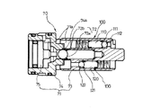
図2及び図3に示すように、本発明による流体力シリンダのシリンダハウジング10は一端から他端まで形成された貫通通路11を有し、また流体を流入したり流出させる第1及び第2の流体ポート10a、10b及び入ってきた流体を放出するドレーンポート10cを備えている。
As shown in FIGS. 2 and 3, the
流体力シリンダはまた第1及び第2の流体通路12、13を有し、第1及び第2の流体通路12、13は、ハウジング10の外面から貫通通路11の内面にかけて形成されている。第1の流体通路12は第1の流体ポート10aと連通し、また第2の流体ポート13は第2の流体ポート10bと連通している。
The fluid force cylinder also has first and second
スリーブ部材20はシリンダハウジング10の貫通通路11と接触して固定され、そして一端から他端にかけて形成した接続部21を備えている。
The
スリーブ部材20は図3に示すように両端に接続部21において軸受22を備え、また、第1及び第2流体通路12、13と連通するように、接続部21における軸受22間には第3及び第4の流体通路23、24が形成されている。
As shown in FIG. 3, the
さらに、スリーブ部材20の接続部21には回転バルブ部材30が接続され、それにより、回転バルブ部材30は、マシンツールのチャックで把持した物体が回転される時に軸受22によって平滑に回転され得る。
Further, the
回転バルブ部材30は、ピストン部材40が摺動可能に接続される、挿入部品30aを備えたバルブロッド31と;予定の厚さをもつようにバルブロッド31の一端に突出しかつシリンダハウジング10の前方に設けられたバルブプレート32とを有している。
The
バルブプレート32はラビリンスシール構造体によってシリンダハウジング10に接続される。バルブプレート32の前方にはシリンダチャンバ33が設けられている。
The
回転バルブ部材30には、第3及び第4の流体通路23、24をシリンダチャンバ33に接続する第5及び第6の流体通路34、35が形成されている。
The
さらに、回転バルブ部材30には、第1の流体圧搾通路34aが設けられ、この第1の流体圧搾通路34aは第3の流体通路23に接続され、そして第6の流体通路35に設けられた後方シリンダチャンバ70のチェックバルブの第2のパイロットスプール75を圧搾するように流体を案内する。また、回転バルブ部材30には、第2の流体圧搾通路35aが設けられ、この第2の流体圧搾通路35aは第4の流体通路24に接続され、そして第5の流体通路34に設けられた前方シリンダチャンバ60のチェックバルブの第1のパイロットスプール65を圧搾するように流体を案内する。
Further, the
回転バルブ部材30は、ピストン部材40が前後に動く際に、チャックのジョーで把持された物体と共に回転するので、回転バルブ部材30のバルブプレート32はラビリンスシール構造体によってシリンダハウジング10とシールされ、バルブプレート32とシリンダハウジング10との間に室を形成するように設けた多数の突起部は多数の溝に係合されるが、互いに接触しない。
The
一方、ピストン部材40はね回転バルブ部材30の挿入部品30aに結合され、そして前後に摺動するようにバルブロッド31に取付けたピストンロッド41を備えている。ピストンプレート42はシリンダチャンバ33を前方及び後方シリンダチャンバ33a、33bに分割しかつ前方及び後方シリンダチャンバ33a、33bシールするようにピストンロット41の周囲に沿って突出されている。
On the other hand, the
さらに、回転バルブ部材30の前方には、シリンダチャンバ33をシールするための本体部材50が設けられている。
Further, a
本体部材50は結合開口50aを備え、コリ結合開口50aにピストンロッド41がシールして接続される。従って、ピストン部材40がシリンダチャンバ33内に供給する流体の圧力によって前方へ動く際に、ピストンロッド41は本体部材50の前方面に突出し、それによりピストンロッド41に接続されたマシンツールのチャックのジョーは把持したり解放される。
The
前方及び後方シリンダチャンバ60、70のチェックバルブは回転バルブ部材30に設けられ、それにより、回転バルブ部材30の第5及び第6の流体通路34、35を通って前方及び後方シリンダチャンバ33a、33bに供給された流体は、一方向に流れるように制御される。
The check valves for the front and
前方シリンダチャンバ60のチェックバルブには、回転バルブ部材30における第5の流体通路34が設けられ、また第5の流体通路34に連通して形成した第1の流体通路61aを含む第1のバルブハウジング61に予定の圧力又はそれより高い圧力で流体を供給する時のみ、第1の流体通路61aを開放する第1のカットオフ手段62が設けられる。
The check valve of the
図3及び図4を参照すると、第1のバルブハウジング61は、回転バルブ部材30の第5の流体通路34に設けられ、そして
第5の流体通路34に連通して形成した第1の流体通路61aを備え、前面に第1のボール着座溝64aを備えた第1の基体部材64と;
第1の基体部材64に接続され、ピストンプレート42を通って本体部材50の内側面に一端を結合し、また第5の流体通路34を前方シリンダチャンバ33aに連通させる第1の流体通路61aを備えた第1のガイド突出部63と;
流体の供給圧力で動くように第1の基体部材64の後方部分に設けられた第1のパイロットスプール65と;
を有している。
Referring to FIGS. 3 and 4, the
A
A
have.
さらに、第1の流体通路61aを遮断する第1のカットオフ手段62は、第1の基体部材64の第1のボール着座溝64aに固定した第1のボール部材62aと、第1の流体通路61aに第1のボール部材62aを弾性的に支持する第1のコイルばね62bとを備えている。
Further, the first cutoff means 62 for blocking the
従って、第1のボール部材62aは、第1のボール着座溝64aに固定することで、第1の流体通路61aをブロックするように第1のコイルばね62bで弾性的に支持されている。
Accordingly, the
この状態において、第1のボール部材62aを押すのに十分高い圧力で第5の流体通路34を通って第1の流体通路61aに流体が供給される時のみ、第1の流体通路61aは開放され、前方シリンダチャンバ33aに流体を供給する。
In this state, the
前方シリンダチャンバ33aに流体が供給される際には、流体は同時に第1の流体圧縮通路34aに供給されるので、流体圧力は第2のパイロットスプール75を押して動かす。
When fluid is supplied to the front cylinder chamber 33a, fluid is simultaneously supplied to the first
そして、図5に示すように、第2のパイロットスプール75は第2のボール部材72aを押して第2の流体通路71aを開放し、後方シリンダチャンバ33bに充填した流体を第6の流体通路35を介して放出させる。
Then, as shown in FIG. 5, the
さらに、後方シリンダチャンバ70のチェックバルブは、回転バルブ部材30における第6の流動通路35に設けられ、また後方シリンダチャンバ70のチェックバルブには、第6の流動通路35に連通して形成した第2の流体通路71aを含む第2のバルブハウジング71内に予定の圧力又はそれより高い圧力で流体を供給する時のみ、第2の流体通路71aを開放させる第2のカットオフ手段72が設けられている。
Further, the check valve of the
図3〜図5を参照すると、第2のバルブハウジング71は、回転バルブ部材30の第6の流動通路35に設けられ、そして 第5の流体通路34に連通して形成した第2の流体通路71aを備え、前面に第2のボール着座溝74aを備えた第2の基体部材74と;
第2の基体部材74に接続され、ピストンプレート42を通って本体部材50の内側面に一端を結合し、また第6の流体通路35を後方シリンダチャンバ33bに連通させる第2の流体通路71aを備えた第2のガイド突出部73と;
流体の供給圧力で動くように第2の基体部材74の後方部分に設けられた第2のパイロットスプール75と;
を有している。
Referring to FIGS. 3 to 5, the
A
A
have.
さらに、第2の流体通路71aを遮断する第2のカットオフ手段72は、第2の基体部材74の第2のボール着座溝74aに固定した第2のボール部材72aと、第2の流体通路71aに第1のボール部材72aを弾性的に支持する第2のコイルばね72bとを備えている。
Further, the second cut-off means 72 for blocking the
従って、第2のボール部材72aは、第2のボール着座溝74aに固定することで、第2の流体通路71aをブロックするように第2のコイルばね72bで弾性的に支持されている。
Therefore, the
この状態において、第2のボール部材72aを押すのに十分高い圧力で第6の流体通路35を通って第2の流体通路71aに流体が供給される時のみ、第2の流体通路71aは開放され、後方シリンダチャンバ33bに流体を供給する。
In this state, the
後方シリンダチャンバ33bに流体が供給される際には、流体は同時に第2の流体圧縮通路35aに供給されるので、流体圧力は第1のパイロットスプール65を押して動かす。
When the fluid is supplied to the rear cylinder chamber 33b, the fluid is simultaneously supplied to the second
そして、第1のパイロットスプール65は第1のボール部材62aを押して第1の流体通路61aを開放し、前方シリンダチャンバ33aに充填した流体を第5の流体通路34を介して放出させる。
Then, the
一方、第2のバルブハウジング71の第2のガイド突出部73は、前方シリンダチャンバ33a及び後方シリンダチャンバ33bに過剰圧力が発生する際に、前方シリンダチャンバ33a及び後方シリンダチャンバ33bを連通させることによりシリンダチャンバ33の圧力を低下させる減圧手段100を備えている。
On the other hand, the
図5を参照すると、減圧手段100は、
第2のガイド突出部73を通って前方シリンダチャンバ33a及び後方シリンダチャンバ33bに連通するように形成した第1及び第2のシリンダ接続経路110、120と;
第1のシリンダ接続経路110に設けられ、前方シリンダチャンバ33aから後方シリンダチャンバ33bへ予定の圧力又はそれより高い圧力で流体が圧縮される時のみ第1のシリンダ接続経路110を開放するように第3のコイルばね111で弾性的に支持された第3のボール部材112と;
第2のシリンダ接続経路120に設けられ、後方シリンダチャンバ33bから前方シリンダチャンバ33aへ予定の圧力又はそれより高い圧力で流体が圧縮される時のみ第2のシリンダ接続経路120を開放するように第4のコイルばね121で弾性的に支持された第4のボール部材122と;
を有している。
Referring to FIG. 5, the decompression means 100 is
First and second
The first
The second
have.
従って、後方シリンダチャンバ33bに流体が供給され、ピストンプレート42を圧搾してピストン部材40を前方へ動かす際に、後方シリンダチャンバ33bに過剰な流体圧力が加わると、第4のボール部材122はこの過剰な流体圧力によって押されて、第2のシリンダ接続経路120を開放する。
Therefore, when the fluid is supplied to the rear cylinder chamber 33b and the
第2のシリンダ接続経路120が開放されると、後方シリンダチャンバ33b内の流体は、第2のシリンダ接続経路120を通って前方シリンダチャンバ33aへ放出され、こうして流体が前方シリンダチャンバ33aへ放出されると、後方シリンダチャンバ33bは減圧する。
When the second
後方シリンダチャンバ33bが減圧されると、第4のボール部材122は、第4のコイルばね121の弾性復帰力によって元の位置へ戻り、第2のシリンダ接続経路120を閉塞する。
When the rear cylinder chamber 33 b is depressurized, the
従って、前方シリンダチャンバ33aに流体が供給され、ピストンプレート42を圧搾してピストン部材40を後方へ動かす際に、前方シリンダチャンバ33aに過剰な流体圧力が加わると、第3のボール部材112はこの過剰な流体圧力によって押されて、第1のシリンダ接続経路110を開放する。
Accordingly, when fluid is supplied to the front cylinder chamber 33a and the
第1のシリンダ接続経路110が開放されると、前方シリンダチャンバ33a内の流体は、第1のシリンダ接続経路110を通って後方シリンダチャンバ33bへ放出され、こうして流体が後方シリンダチャンバ33bへ放出されると、前方シリンダチャンバ33aは減圧する。
When the first
前方シリンダチャンバ33aが減圧されると、第3のボール部材112は、第3のコイルばね111の弾性復帰力によって元の位置へ戻り、第1のシリンダ接続経路110は閉塞される。
When the front cylinder chamber 33a is depressurized, the
以下、本発明の流体力シリンダの動作について詳細に説明する。 Hereinafter, the operation of the fluid force cylinder of the present invention will be described in detail.
シリンダハウジング10の第1の流体ポート10aは、第1の流体通路12、スリーブ部材20の第3の流体通路23、回転バルブ部材30の第5の流体通路34、チェックバルブ60の第1の流体通路61a、及び前方シリンダチャンバ33aに順次接続され、そしてまた第3の流体通路23と連通する第1の流体圧縮通路34aを介して後方シリンダチャンバのチェックバルブ70に接続される。
The first
シリンダハウジング10の第2の流体ポート10bは、第2の流体通路13、スリーブ部材20の第4の流体通路24、回転バルブ部材30の第6の流体通路35、後方シリンダチャンバのチェックバルブ70の第2の流体通路71a、及び後方シリンダチャンバ33bに順次接続され、そしてまた第4の流体通路24と連通する第2の流体圧縮通路35aを介して前方シリンダチャンバのチェックバルブ60に接続される。
The second
前方シリンダチャンバ33aには、ピストン部材40を引くことにより流体が充填される。
The front cylinder chamber 33 a is filled with fluid by pulling the
特に、流体が予定の圧力又はそれより高い圧力で第2の流体ポート10bに供給されると、流体は、第2、第4及び第6の流体通路13、24、35を通って後方シリンダチャンバのチェックバルブ70の第2の流体通路71aに入り込み、それにより第2のボール部材72aは押されて、第2の流体通路71aを開放する。
In particular, when fluid is supplied to the second
それにより、開放した第2の流体通路71aを通って後方シリンダチャンバ33bに流体が供給され、その結果、ピストンプレート42は押圧され、ピストン部材40を前進させる。
Thereby, the fluid is supplied to the rear cylinder chamber 33b through the opened
ピストン部材40が前進すると、ピストン部材40はそれに接続したチャックのジョーを把持させ、そして流体圧力によりジョーの把持をしっかりと保持する。
As the
さらに、第4の流体通路24に供給された流体は、第6の流体通路35を通って後方シリンダチャンバのチェックバルブ70に供給され、同時に第2の流体圧縮通路35aに供給され、前方シリンダチャンバのチェックバルブ60の第1のパイロットスプール65を押し動かす。
Further, the fluid supplied to the
こうして押し動かされている間に、第1のパイロットスプール65は第1のボール部材62aを押して第1の流体通路61aを開放する。
While being pushed and moved in this way, the
従って、前方シリンダチャンバ33aに充填された流体は、開放した第1の流体通路61a及び第5の流体通路34を通過し、そして流体はシリンダハウジング10の第1の流体ポート10aに放出させる。
Accordingly, the fluid filled in the front cylinder chamber 33 a passes through the opened
これに対して、流体が予定の圧力又はそれより高い圧力で第1の流体ポート10aに供給されると、流体は、第1、第3及び第5の流体通路12、23、34を通って第1の流体通路61aに入り込み、それにより第1のボール部材62aは押されて、第1の流体通路61aを開放する。
In contrast, when fluid is supplied to the first
それにより、開放した第1の流体通路61aを通って前方シリンダチャンバ33aに流体が供給され、その結果、ピストンプレート42は押圧され、ピストン部材40を後退させる。
Thereby, the fluid is supplied to the front cylinder chamber 33a through the opened
ピストン部材40が後退すると、ピストン部材40はそれに接続したチャックのジョーを解放させる。
When the
さらに、第3の流体通路23に供給された流体は、第5の流体通路34を通って前方シリンダチャンバのチェックバルブ60に供給され、同時に第1の流体圧縮通路34aに供給され、後方シリンダチャンバのチェックバルブ70の第2のパイロットスプール75を押し動かす。
Further, the fluid supplied to the
こうして押し動かされている間に、第2のパイロットスプール75は第2のボール部材72aを押して第2の流体通路71aを開放する。
While being pushed and moved in this manner, the
従って、後方シリンダチャンバ33bに充填された流体は、開放した第2の流体通路71a及び第6の流体通路35を通過し、そして流体はシリンダハウジング10の第2の流体ポート10bに放出させる。
Therefore, the fluid filled in the rear cylinder chamber 33 b passes through the opened
上述のように、ピストン部材40が前方及び後方シリンダチャンバ33a及び33bに流体を供給することによって前後に動く際に、ピストン部材40は、ピストンプレート42を通過することによってピストンプレート42に接続された第1、第2のバルブハウジング61,71の第1、第2のガイド突起部63、73に沿って動く。
As described above, as the
さらに、前方及び後方シリンダチャンバ33a及び33bに流体を供給している間に、過剰圧力が生じても、後方シリンダチャンバのチェックバルブ70に設けた減圧手段100が圧力を低減し、過剰圧力で生じ得るマシンツールの機能不全やシリンダ本体の耐久性の減少を防ぐことができる。
Furthermore, even if an excessive pressure occurs while supplying fluid to the front and rear cylinder chambers 33a and 33b, the pressure reducing means 100 provided in the
シリンダハウジング10とスリーブ部材20との間、回転バルブ部材30とピストン部材40との間、回転バルブ部材30と本体部材50との間、又はピストンプレート42の周囲部と本体部材50の内側面との間を通常の仕方でシールするOリングが設けられ得る。
Between the
以上説明したように、本発明によれば、コンパクトで構造が簡単な流体力シリンダが提供され、製造プロセス及びコストの経済性に貢献する。 As described above, according to the present invention, a fluid force cylinder that is compact and simple in structure is provided, which contributes to the economical efficiency of the manufacturing process and cost.
さらに、本発明によれば、前方及び後方シリンダチャンバに供給される流体の流れを制御するチェックバルブを備え、チェックバルブのバルブハウジングにピストン部材の往復動を案内するガイド突起部を備え、従って別個のガイドピンを備える必要のない新規の流体力シリンダが提供される。 In addition, according to the present invention, a check valve for controlling the flow of fluid supplied to the front and rear cylinder chambers is provided, and a guide projection for guiding the reciprocating motion of the piston member is provided in the valve housing of the check valve, and thus separate. There is provided a novel fluid force cylinder which does not need to be provided with a plurality of guide pins.
さらに、本発明によれば、動作中に前方及び後方シリンダチャンバ内に発生した過剰圧力を低減する減圧手段をチェックバルブのバルブハウジング内に一体的に設け、従って別個の減圧バルブすなわちリリーフバルブを備えていない流体力シリンダが提供される。 Furthermore, according to the present invention, a pressure reducing means for reducing excess pressure generated in the front and rear cylinder chambers during operation is integrally provided in the valve housing of the check valve, and therefore a separate pressure reducing valve or relief valve is provided. A non-hydrodynamic cylinder is provided.
当業者には明らかなように、本発明の精神及び範囲から逸脱することなしに本発明に対して種々の変更及び変形がなされ得る。本発明は、特許請求の範囲内およびそれらの等価の範囲内の種々の変更及び変形を包含する。 It will be apparent to those skilled in the art that various modifications and variations can be made to the present invention without departing from the spirit and scope of the invention. The invention encompasses various changes and modifications within the scope of the claims and their equivalents.
10:シリンダハウジング
11:貫通通路
12:第1の流体通路
13:第2の流体通路
20:スリーブ部材
21:接続部品
22:軸受
23:第3の流体通路
24:第4の流体通路
30:回転バルブ部材
31:バルブロッド
32:バルブプレート
33:シリンダチャンバ
33a:前方シリンダチャンバ
33b:後方シリンダチャンバ
34:第5の流体通路
35:第6の流体通路
40:ピストン部材
41:ピストンロッド
42:ピストンプレート
50:本体部材
60:前方シリンダチャンバ用チェックバルブ
61:第1のバルブハウジング
61a:第1の流体通路
62:第1のカットオフ手段
63:第1のガイド突起部
70:後方シリンダチャンバ用チェックバルブ
71:第2のバルブハウジング
71a:第2の流体通路
72:第2のカットオフ手段
73:第2のガイド突起部
100:減圧手段
110:第1のシリンダ接続経路
111:第3のコイルばね
112:第3のボール部材
120:第2のシリンダ接続経路
121:第4のコイルばね
122:第4のボール部材
10: Cylinder housing 11: Through passage 12: First fluid passage 13: Second fluid passage 20: Sleeve member 21: Connection component 22: Bearing 23: Third fluid passage 24: Fourth fluid passage 30: Rotation Valve member 31: Valve rod 32: Valve plate 33: Cylinder chamber 33a: Front cylinder chamber 33b: Rear cylinder chamber 34: Fifth fluid passage 35: Sixth fluid passage 40: Piston member 41: Piston rod 42: Piston plate 50: Body member 60: Check valve for front cylinder chamber 61:
Claims (1)
シリンダハウジング(10)の貫通通路(11)に接触して固定され、一端から他端まで形成された接続部品(21)を備え、かつ接続部品(21)における軸受(22)及び第1及び第2の流体通路(12、13)に連通する第3及び第4の流体通路(23、24)を備えたスリーブ部材(20)と;
一端を接続部品(21)に結合されたバルブロッド(31)及びシリンダハウジング(10)の前方に設けられたバルブプレート(32)を備え、バルブプレート(32)の一側端部にシリンダチャンバ(33)が設けられ、また、第3及び第4の流体通路(23、24)をシリンダチャンバ(33)に接続するように形成した第5及び第6の流体通路(34、35)を備えた回転バルブ部材(30)と;
ピストンプレート(42)を前後に摺動可能に動かすようにバルブロッド(31)に固定したピストンロッド(41)を備え、ピストンプレート(42)がピストンロッド(41)から突出してシリンダチャンバ(33)を前方及び後方シリンダチャンバ(33a、33b)に分割しかつピストンロッド(41)の周囲部に対して前方及び後方シリンダチャンバ(33a、33b)をシールするピストン部材(40)と;
バルブプレート(32)の前方に設けられ、シリンダチャンバ(33)をシールするように流体の供給されるシリンダチャンバ(33)を含む本体部材(50)と;
回転バルブ部材(30)における第5の流体通路(34)に設けられ、第5の流体通路(34)に連通して設けた第1の流体通路(61a)を含む第1のバルブハウジング(61)に予定の圧力又はそれより高い圧力の流体が供給される時のみ、第1の流体通路(61a)を開放させる第1のカットオフ手段(62)を備えた前方シリンダチャンバ用チェックバルブ(60)と;
回転バルブ部材(30)における第6の流体通路(35)に設けられ、第6の流体通路(35)に連通して設けた第2の流体通路(71a)を含む第2のバルブハウジング(71)に予定の圧力又はそれより高い圧力の流体が供給される時のみ、第2の流体通路(71a)を開放させる第2のカットオフ手段(72)を備えた後方シリンダチャンバ用チェックバルブ(70)と;
を有し、
第1のバルブハウジング(61)が、第5の流体通路(34)を前方シリンダチャンバ(33a)に接続する第1の流体通路(61a)を備え、そしてピストンプレート(42)を介して本体部材(50)の内側面に一端を結合するように形成した第1のガイド突起部(63)を備え、
第2のバルブハウジング(71)が、第6の流体通路(35)を後方シリンダチャンバ(33b)に接続する第2の流体通路(71a)を備え、そしてピストンプレート(42)を介して本体部材(50)の内側面に一端を結合するように形成した第2のガイド突起部(73)を備え、
また、第2のガイド突起部(73)に、前方又は後方シリンダチャンバ(33a、33b)に過剰圧が発生した際に前方及び後方シリンダチャンバ(33a、33b)を連通させることによりシリンダチャンバ(33)における圧力を低下させる減圧手段(100)が設けられ、
減圧手段(100)が、
第2のガイド突起部(73)を介して前方及び後方シリンダチャンバ(33a、33b)に連通するように形成された第1及び第2のシリンダ接続経路(110、120)と;
第1のシリンダ接続経路(110)に設けられ、前方シリンダチャンバ(33a)から後方シリンダチャンバ(33b)へ予定の圧力又はそれより高い圧力で流体が圧縮される時のみ第1のシリンダ接続経路(110)を開放するように第3のコイルばね(111)で弾性的に支持された第3のボール部材(112)と;
第2のシリンダ接続経路(120)に設けられ、後方シリンダチャンバ(33b)から前方シリンダチャンバ(33a)へ予定の圧力又はそれより高い圧力で流体が圧縮される時のみ第2のシリンダ接続経路(120)を開放するように第4のコイルばね(121)で弾性的に支持された第4のボール部材(122)と;
を有することを特徴とする流体力シリンダ。 A cylinder housing (10) comprising a through passage (11) formed from one end to the other end, and comprising first and second fluid passages (12, 13) from the outer surface to the inner surface of the through passage (11);
A connecting part (21) formed in contact with the through passage (11) of the cylinder housing (10) and fixed from one end to the other end is provided, and the bearing (22) and the first and first parts in the connecting part (21) A sleeve member (20) with third and fourth fluid passages (23, 24) communicating with the two fluid passages (12, 13);
A valve rod (31) having one end coupled to the connecting part (21) and a valve plate (32) provided in front of the cylinder housing (10) are provided, and a cylinder chamber ( 33) and provided with fifth and sixth fluid passages (34, 35) formed to connect the third and fourth fluid passages (23, 24) to the cylinder chamber (33). A rotary valve member (30);
A piston rod (41) fixed to the valve rod (31) so as to move the piston plate (42) back and forth is slidable, and the piston plate (42) protrudes from the piston rod (41) to the cylinder chamber (33). A piston member (40) which divides the front and rear cylinder chambers (33a, 33b) and seals the front and rear cylinder chambers (33a, 33b) against the periphery of the piston rod (41);
A body member (50) including a cylinder chamber (33) provided in front of the valve plate (32) and supplied with fluid to seal the cylinder chamber (33);
A first valve housing (61) including a first fluid passage (61a) provided in the fifth fluid passage (34) of the rotary valve member (30) and provided in communication with the fifth fluid passage (34). Only when a fluid at a predetermined pressure or higher is supplied to the front cylinder chamber check valve (60) having the first cutoff means (62) for opening the first fluid passage (61a). )When;
A second valve housing (71) including a second fluid passage (71a) provided in the sixth fluid passage (35) of the rotary valve member (30) and provided in communication with the sixth fluid passage (35). Only when a fluid at a predetermined pressure or higher is supplied to the rear cylinder chamber check valve (70) having the second cutoff means (72) for opening the second fluid passage (71a). )When;
Have
The first valve housing (61) includes a first fluid passage (61a) connecting the fifth fluid passage (34) to the front cylinder chamber (33a), and the body member via the piston plate (42). A first guide protrusion (63) formed to join one end to the inner surface of (50),
The second valve housing (71) includes a second fluid passage (71a) connecting the sixth fluid passage (35) to the rear cylinder chamber (33b), and the body member via the piston plate (42). A second guide projection (73) formed to join one end to the inner surface of (50),
In addition, when excessive pressure is generated in the front or rear cylinder chamber (33a, 33b), the front and rear cylinder chambers (33a, 33b) are communicated with the second guide protrusion (73) to thereby provide the cylinder chamber (33). ) Pressure reducing means (100) for reducing the pressure in
The decompression means (100)
First and second cylinder connection paths (110, 120) formed to communicate with the front and rear cylinder chambers (33a, 33b) via the second guide protrusions (73);
The first cylinder connection path (110) is provided in the first cylinder connection path (110) and only when the fluid is compressed from the front cylinder chamber (33a) to the rear cylinder chamber (33b) at a predetermined pressure or higher pressure. A third ball member (112) elastically supported by a third coil spring (111) to open 110);
The second cylinder connection path (120) is provided in the second cylinder connection path (120) and only when the fluid is compressed from the rear cylinder chamber (33b) to the front cylinder chamber (33a) at a predetermined pressure or higher. A fourth ball member (122) elastically supported by a fourth coil spring (121) to open 120);
Hydraulic cylinder, characterized in that it comprises a.
Applications Claiming Priority (1)
| Application Number | Priority Date | Filing Date | Title |
|---|---|---|---|
| KR1020040052255A KR100573414B1 (en) | 2004-07-06 | 2004-07-06 | Fluid Pressure Cylinder |
Publications (2)
| Publication Number | Publication Date |
|---|---|
| JP2006021313A JP2006021313A (en) | 2006-01-26 |
| JP4194566B2 true JP4194566B2 (en) | 2008-12-10 |
Family
ID=34981360
Family Applications (1)
| Application Number | Title | Priority Date | Filing Date |
|---|---|---|---|
| JP2005021512A Active JP4194566B2 (en) | 2004-07-06 | 2005-01-28 | Fluid force cylinder |
Country Status (9)
| Country | Link |
|---|---|
| EP (1) | EP1614907B1 (en) |
| JP (1) | JP4194566B2 (en) |
| KR (1) | KR100573414B1 (en) |
| CN (1) | CN100334361C (en) |
| AT (1) | ATE377713T1 (en) |
| DE (1) | DE602005003170T2 (en) |
| DK (1) | DK1614907T3 (en) |
| ES (1) | ES2293492T3 (en) |
| TW (1) | TWI257975B (en) |
Families Citing this family (7)
| Publication number | Priority date | Publication date | Assignee | Title |
|---|---|---|---|---|
| EP1947372A1 (en) * | 2007-01-18 | 2008-07-23 | Kongsberg Automotive AS | A gear shift system with a power assistance system |
| JP5337221B2 (en) * | 2011-10-07 | 2013-11-06 | パスカルエンジニアリング株式会社 | Fluid pressure cylinder and clamping device |
| KR101512488B1 (en) * | 2013-08-12 | 2015-04-16 | 주식회사 에스엠씨 척3000 | Check valves for hydraulic cylinders |
| KR20160099175A (en) | 2015-02-11 | 2016-08-22 | 주식회사 삼천리기계 | Hydraulic Rotary Cylinder of Machine Tool having Hydraulic Chuck |
| CN109414765B (en) * | 2016-07-29 | 2020-07-31 | 株式会社北川铁工所 | Structure and rotary cylinder |
| JP6867216B2 (en) * | 2017-04-11 | 2021-04-28 | 豊興工業株式会社 | Rotary cylinder device |
| KR20210043864A (en) | 2019-10-14 | 2021-04-22 | 주식회사 삼천리기계 | Sleeve of rotary hydraulic cylinder |
Family Cites Families (8)
| Publication number | Priority date | Publication date | Assignee | Title |
|---|---|---|---|---|
| FR2055206A5 (en) * | 1970-05-09 | 1971-05-07 | Pinto Mario Spa | |
| JPS55144949A (en) | 1979-04-26 | 1980-11-12 | Kitagawa Tekkosho:Kk | Cooling mechanism for rotary fluid pressure cylinder |
| US4418612A (en) * | 1981-05-28 | 1983-12-06 | Vickers, Incorporated | Power transmission |
| US4747337A (en) | 1985-02-18 | 1988-05-31 | Kitagawa Iron Works Co., Ltd. | Rotary fluid cylinders for operating chucks |
| JPS60215109A (en) * | 1985-02-22 | 1985-10-28 | Kitagawa Tekkosho:Kk | Rotary fluid pressure cylinder with safety mechanism |
| DE3683666D1 (en) * | 1985-04-11 | 1992-03-12 | Beringer Hydraulik Gmbh | LEAK-FREE BRAKE LOCK VALVE. |
| JPH11264481A (en) | 1998-03-16 | 1999-09-28 | Howa Mach Ltd | Pilot check valve and rotary cylinder structure |
| KR200370456Y1 (en) | 2004-07-06 | 2004-12-17 | 주식회사 삼천리기계 | Fluid Pressure Cylinder |
-
2004
- 2004-07-06 KR KR1020040052255A patent/KR100573414B1/en active IP Right Grant
- 2004-12-23 TW TW093140268A patent/TWI257975B/en not_active IP Right Cessation
-
2005
- 2005-01-06 EP EP05250021A patent/EP1614907B1/en not_active Not-in-force
- 2005-01-06 AT AT05250021T patent/ATE377713T1/en not_active IP Right Cessation
- 2005-01-06 DE DE602005003170T patent/DE602005003170T2/en active Active
- 2005-01-06 ES ES05250021T patent/ES2293492T3/en active Active
- 2005-01-06 DK DK05250021T patent/DK1614907T3/en active
- 2005-01-12 CN CNB2005100020504A patent/CN100334361C/en not_active Expired - Fee Related
- 2005-01-28 JP JP2005021512A patent/JP4194566B2/en active Active
Also Published As
| Publication number | Publication date |
|---|---|
| CN1719047A (en) | 2006-01-11 |
| TWI257975B (en) | 2006-07-11 |
| JP2006021313A (en) | 2006-01-26 |
| CN100334361C (en) | 2007-08-29 |
| TW200602565A (en) | 2006-01-16 |
| EP1614907B1 (en) | 2007-11-07 |
| EP1614907A1 (en) | 2006-01-11 |
| KR20060004735A (en) | 2006-01-16 |
| DK1614907T3 (en) | 2008-01-28 |
| KR100573414B1 (en) | 2006-04-26 |
| DE602005003170D1 (en) | 2007-12-20 |
| ATE377713T1 (en) | 2007-11-15 |
| DE602005003170T2 (en) | 2008-09-04 |
| ES2293492T3 (en) | 2008-03-16 |
Similar Documents
| Publication | Publication Date | Title |
|---|---|---|
| JP4194566B2 (en) | Fluid force cylinder | |
| US6848257B2 (en) | Master cylinder comprising a fluid and replenishing seal | |
| EP1048854A2 (en) | Servo-driving pilot-type solenoid valve | |
| JP6665983B2 (en) | Fluid pressure cylinder with booster | |
| CN216142768U (en) | Electro-hydraulic control proportional reversing valve | |
| JP4720401B2 (en) | Booster type fluid pressure cylinder | |
| TWI680235B (en) | Pressure booster and cylinder device comprising same | |
| US6679340B1 (en) | Hydraulic tool | |
| KR20160099175A (en) | Hydraulic Rotary Cylinder of Machine Tool having Hydraulic Chuck | |
| CN210770418U (en) | Two-position three-way electromagnetic directional valve | |
| TWI623363B (en) | Hydraulic drive device for machine tool chuck | |
| KR100564829B1 (en) | Chuck assembly with a sealing member | |
| KR200370456Y1 (en) | Fluid Pressure Cylinder | |
| RU2204742C2 (en) | Two-stage power hydraulic cylinder | |
| JPS60261984A (en) | Double action pressure converter | |
| JPH0137637B2 (en) | ||
| WO2019096982A1 (en) | Cartridge hand pump | |
| JP6227520B2 (en) | Internal pilot type 3 port selector valve | |
| JP7221558B1 (en) | Air-hydro booster, clamping system, robot arm, and processing method | |
| JP2018076909A (en) | Fluid pressure cylinder | |
| CN220037529U (en) | Manual hydraulic control structure and manual hydraulic equipment | |
| CN210450890U (en) | A keep apart check valve for pressing penetrate braking | |
| TWI535959B (en) | Check valve | |
| JP2518697B2 (en) | Sheet valve type pressure oil supply / discharge operation valve | |
| JPH0222188Y2 (en) |
Legal Events
| Date | Code | Title | Description |
|---|---|---|---|
| A131 | Notification of reasons for refusal |
Free format text: JAPANESE INTERMEDIATE CODE: A131 Effective date: 20080116 |
|
| A521 | Request for written amendment filed |
Free format text: JAPANESE INTERMEDIATE CODE: A523 Effective date: 20080416 |
|
| TRDD | Decision of grant or rejection written | ||
| A01 | Written decision to grant a patent or to grant a registration (utility model) |
Free format text: JAPANESE INTERMEDIATE CODE: A01 Effective date: 20080827 |
|
| A01 | Written decision to grant a patent or to grant a registration (utility model) |
Free format text: JAPANESE INTERMEDIATE CODE: A01 |
|
| A61 | First payment of annual fees (during grant procedure) |
Free format text: JAPANESE INTERMEDIATE CODE: A61 Effective date: 20080922 |
|
| R150 | Certificate of patent or registration of utility model |
Ref document number: 4194566 Country of ref document: JP Free format text: JAPANESE INTERMEDIATE CODE: R150 Free format text: JAPANESE INTERMEDIATE CODE: R150 |
|
| FPAY | Renewal fee payment (event date is renewal date of database) |
Free format text: PAYMENT UNTIL: 20111003 Year of fee payment: 3 |
|
| FPAY | Renewal fee payment (event date is renewal date of database) |
Free format text: PAYMENT UNTIL: 20121003 Year of fee payment: 4 |
|
| R250 | Receipt of annual fees |
Free format text: JAPANESE INTERMEDIATE CODE: R250 |
|
| FPAY | Renewal fee payment (event date is renewal date of database) |
Free format text: PAYMENT UNTIL: 20131003 Year of fee payment: 5 |
|
| R250 | Receipt of annual fees |
Free format text: JAPANESE INTERMEDIATE CODE: R250 |
|
| R250 | Receipt of annual fees |
Free format text: JAPANESE INTERMEDIATE CODE: R250 |
|
| R250 | Receipt of annual fees |
Free format text: JAPANESE INTERMEDIATE CODE: R250 |
|
| R250 | Receipt of annual fees |
Free format text: JAPANESE INTERMEDIATE CODE: R250 |
|
| S531 | Written request for registration of change of domicile |
Free format text: JAPANESE INTERMEDIATE CODE: R313531 |
|
| R350 | Written notification of registration of transfer |
Free format text: JAPANESE INTERMEDIATE CODE: R350 |
|
| R250 | Receipt of annual fees |
Free format text: JAPANESE INTERMEDIATE CODE: R250 |
|
| R250 | Receipt of annual fees |
Free format text: JAPANESE INTERMEDIATE CODE: R250 |
|
| R250 | Receipt of annual fees |
Free format text: JAPANESE INTERMEDIATE CODE: R250 |
|
| R250 | Receipt of annual fees |
Free format text: JAPANESE INTERMEDIATE CODE: R250 |
|
| R250 | Receipt of annual fees |
Free format text: JAPANESE INTERMEDIATE CODE: R250 |
|
| R250 | Receipt of annual fees |
Free format text: JAPANESE INTERMEDIATE CODE: R250 |
|
| R250 | Receipt of annual fees |
Free format text: JAPANESE INTERMEDIATE CODE: R250 |
|
| R250 | Receipt of annual fees |
Free format text: JAPANESE INTERMEDIATE CODE: R250 |