JP4194533B2 - Developing roller and image forming apparatus using the same - Google Patents
Developing roller and image forming apparatus using the same Download PDFInfo
- Publication number
- JP4194533B2 JP4194533B2 JP2004179906A JP2004179906A JP4194533B2 JP 4194533 B2 JP4194533 B2 JP 4194533B2 JP 2004179906 A JP2004179906 A JP 2004179906A JP 2004179906 A JP2004179906 A JP 2004179906A JP 4194533 B2 JP4194533 B2 JP 4194533B2
- Authority
- JP
- Japan
- Prior art keywords
- roller
- latent image
- layer
- developing roller
- elastic
- Prior art date
- Legal status (The legal status is an assumption and is not a legal conclusion. Google has not performed a legal analysis and makes no representation as to the accuracy of the status listed.)
- Expired - Fee Related
Links
Images


Description
本発明は、現像ローラに関し、より具体的には、例えば、複写機、プリンタ、ファクシミリ等の受信装置など、画像形成に電子写真方式を採用した装置(以降、電子写真装置と総称する)において主に使用される現像ローラ、並びに、その現像ローラを用いた現像装置及び画像形成装置に関する。 The present invention relates to a developing roller, and more specifically, mainly in an apparatus (hereinafter, collectively referred to as an electrophotographic apparatus) that employs an electrophotographic system for image formation, such as a receiving apparatus such as a copying machine, a printer, or a facsimile. developing roller for use in, and to a developing device and an image forming apparatus using the developing roller.
複写機、ファクシミリ、プリンタなど、その画像形成に電子写真方式を利用する電子写真装置では、その画像形成工程において、各種の目的にあった弾性ローラが利用されている。例えば、一成分現像方式の電子写真装置では、感光体表面に形成された静電潜像を現像剤により顕像化する工程、すなわち、現像工程では、その表面に現像剤が担持されている現像ローラを、潜像担持体としての感光体表面に圧接させて、現像剤を移動させる方法が利用されている。この工程で用いる現像ローラの弾性体層は、その弾性部材を感光体に対して所定の接触幅をもって圧接する必要があり、変形しやすく、同時に変形回復性(セット回復性)にも優れ、かつ現像剤がローラ表面に付着することにかかる表面特性(以下、付着性という)が低いものが望まれる。また、現像器において供給される現像剤を、現像ローラの表層に当接するブレードなどを用いて、弾性体層上に薄層化して担持させる上でも、現像ローラ表面の弾性体層は変形しやすく、変形回復性に優れること、またその現像剤の現像ローラ表面への付着が起き難いことが必要である。 In an electrophotographic apparatus using an electrophotographic system for image formation, such as a copying machine, a facsimile machine, and a printer, an elastic roller suitable for various purposes is used in the image forming process. For example, in a one-component development type electrophotographic apparatus, a process in which an electrostatic latent image formed on a surface of a photoreceptor is visualized with a developer, that is, in a development process, a developer carrying a developer on the surface is developed. A method is used in which a developer is moved by bringing a roller into pressure contact with a surface of a photoreceptor as a latent image carrier. The elastic layer of the developing roller used in this step needs to press the elastic member with a predetermined contact width against the photosensitive member, is easily deformed, and at the same time has excellent deformation recovery (set recovery), and What has low surface characteristics (hereinafter referred to as adhesion) required for the developer to adhere to the roller surface is desired. In addition, the elastic layer on the surface of the developing roller is easily deformed even when the developer supplied in the developing unit is thinly carried on the elastic layer using a blade that contacts the surface layer of the developing roller. In addition, it is necessary to have excellent deformation recovery properties, and it is difficult for the developer to adhere to the surface of the developing roller.
その他、画像形成工程において、直接あるいは間接的に感光体表面と当接または圧接する形態で使用される弾性ローラとしては、接触帯電型の帯電器において利用される帯電ローラがある。また、現像された感光体表面の現像剤からなる画像(トナー像)をコピー用紙などの転写紙上に転写する工程においても、感光体表面の帯電と異なる極性に帯電する転写ローラが利用される。これら帯電ローラや転写ローラなども、その弾性部材を感光体と所定の接触幅をもって圧接する必要があり、変形しやすく、また、変形回復性にも優れるもの、そして表面への現像剤の付着性の低いものが望まれる。 In addition, in the image forming process, as an elastic roller that is used in a form that directly or indirectly contacts or presses the surface of the photoreceptor, there is a charging roller used in a contact charging type charger. Also in the process of transferring an image (toner image) made of the developer on the surface of the developed photoreceptor onto a transfer sheet such as a copy sheet, a transfer roller that is charged with a polarity different from the charge on the surface of the photoreceptor is used. These charging roller and transfer roller also require that the elastic member be pressed against the photosensitive member with a predetermined contact width, are easily deformed, have excellent deformation recovery properties, and adherence of the developer to the surface. A low one is desired.
上記のとおり電子写真装置に用いられる弾性ローラは、個々の用途に応じた機能、例えば、現像ローラにおいては現像剤の担持特性、また、帯電ローラや転写ローラでは、帯電性に関連する導電特性など、個々の用途により異なる性能に加え、弾性ローラとして共通する要求性能も多岐に渡る。 As described above, the elastic roller used in the electrophotographic apparatus has a function corresponding to each application, for example, a developer carrying characteristic in the developing roller, and a conductive characteristic related to charging property in the charging roller or the transfer roller. In addition to the different performance depending on each application, the required performance common as an elastic roller also varies.
この弾性ローラとして共通する要求性能の中でも、適正な当接状態を維持する上で重要となる、変形回復性(すなわち、セット性)に対して、従来より、様々な提案がなされている。例えば、弾性ローラの最も外側に位置する表層として被覆された樹脂層においてウレタン樹脂を用いることにより、比較的好ましい性能が得られることが知られている。 Among the required performance common to the elastic roller, various proposals have conventionally been made for deformation recovery (that is, setability), which is important in maintaining an appropriate contact state. For example, it is known that relatively preferable performance can be obtained by using a urethane resin in a resin layer coated as a surface layer located on the outermost side of the elastic roller.
本発明者らは、特開2002-257130公報において、弾性層の硬度、圧縮永久歪みと、その外周の樹脂層の永久伸びを、それぞれ好ましい範囲とし組み合わせることにより、変形回復性(セット性)に優れた2層構成の弾性ローラとなることを開示している。 In the Japanese Patent Application Laid-Open No. 2002-257130, the inventors combined deformation hardness (compression set) and compression set and permanent elongation of a resin layer on the outer periphery thereof within preferable ranges, respectively. It discloses that the elastic roller has an excellent two-layer structure.
一方、変形回復性が得られ易い柔軟な材料を表層に用いた場合には、表層表面への現像剤などの付着性が高くなり、そしてその強度は低くなる傾向がある。このような表層を有する弾性ローラを現像ローラとして用いた場合、現像剤が表面に付着して感光体への良好な現像剤の供給操作に支障が生じたり、樹脂層表面のヒビや割れや削れが起きたりして、良質な画像が得られ難くなる。 On the other hand, when a flexible material that easily obtains deformation recovery is used for the surface layer, the adhesion of the developer or the like to the surface of the surface layer tends to increase, and the strength tends to decrease. When an elastic roller having such a surface layer is used as a developing roller, the developer adheres to the surface, which may hinder the operation of supplying a good developer to the photosensitive member, or the resin layer surface may be cracked, cracked or scraped. May occur, making it difficult to obtain good quality images.
特開2000-330370公報には、導電性弾性層の表面にアルキッド変性シリコーン化合物とメラミン樹脂との混合物を硬化させてなる樹脂を含有する材料からなる被覆層を有するトナー担持体(現像ローラ)を用いることにより、被覆層に割れや削れが生じることがなく、各種画像不良の発生を防止することが開示されている。 Japanese Patent Laid-Open No. 2000-330370 discloses a toner carrier (developing roller) having a coating layer made of a material containing a resin obtained by curing a mixture of an alkyd-modified silicone compound and a melamine resin on the surface of a conductive elastic layer. It is disclosed that, when used, the coating layer is not cracked or scraped, and various image defects are prevented from occurring.
また、糖アルコールを用いた電子写真用ローラに関するものとして、特許第3143545号明細書があげられるが、本発明とは趣旨を異にするものである。この明細書に開示される帯電部材は、その樹脂層に、エチレン性不飽和基を有する単量体をカーボンおよびポリオールの存在下で重合させることにより得られる重合体混合物、とポリイソシアネートを反応させることにより得られる導電性ポリウレタン樹脂を含有することを特徴とする。そして、この構成により、高温高湿から低温低湿に至る環境下において安定した導電性を有し、感光体の放電絶縁破壊も生じることなく、感光体表面を非常に均一に帯電することができ、結果として極めて優れた画像を供給し得ることを開示している。その中で、ポリオールに用いられる材料として列記する中に多価アルコール、さらにはその多価アルコールの列記の中に糖アルコールがあげられているが、糖アルコールを用いることによる特定の効果に関する記載はない。
近年、電子写真装置に使用される弾性ローラの要求性能は、電子写真装置の高速化、画質の高品位化に伴って、より高度なものとなってきており、さらなる向上が一層求められている。特に表層材料において、柔軟性やセット回復性と共に、現像剤に関する低付着性及び被膜強度の両方の特性の維持、あるいはこれらの特性の更なる向上がなお求められている。 In recent years, the required performance of an elastic roller used in an electrophotographic apparatus has become more advanced as the electrophotographic apparatus is speeded up and the image quality is improved, and further improvement is required. . In particular, in surface layer materials, there is still a need to maintain the properties of both low adhesion and film strength with respect to the developer, as well as flexibility and set recoverability, or to further improve these properties.
本発明はこのような電子写真装置に用いる弾性ローラにおける課題を解決することを目的とするものである。特に、本発明の目的は、ウレタン樹脂を含む樹脂層を表層とする現像ローラとして好適な弾性ローラにおいて、付着性を低減し、被膜の強度を向上し優れた耐久性を持つ樹脂表層を採用する弾性ローラを提供することにある。また、その弾性ローラを現像ローラとし用いた現像装置や画像形成装置を提供することにある。 The object of the present invention is to solve the problems of the elastic roller used in such an electrophotographic apparatus. In particular, an object of the present invention is to adopt a resin surface layer having excellent durability and reducing adhesion, improving the strength of a film, and an elastic roller suitable as a developing roller having a resin layer containing a urethane resin as a surface layer. It is to provide an elastic roller. Another object of the present invention is to provide a developing device and an image forming apparatus using the elastic roller as a developing roller .
本発明者らは、上記の課題を解決すべく、鋭意研究・検討を進めた。ウレタン樹脂において、一般的に柔軟性のあるものは付着性が高く、逆に、付着性が低く良好なものは柔軟性に劣っている傾向があることが確認された。また柔軟性の高いウレタン樹脂にカーボンブラックやその他フィラーを添加すると、現像剤および該現像剤に含まれる外添成分などの付着にかかる表面特性、すなわち付着性は低くなるが、柔軟性やセット回復性が得られなくなってしまう。 In order to solve the above-mentioned problems, the present inventors have intensively studied and studied. Among urethane resins, it has been confirmed that generally those having flexibility have high adhesion, and conversely, those having low adhesion and good tend to be inferior in flexibility. If carbon black or other fillers are added to highly flexible urethane resin, the surface properties of the developer and external additives contained in the developer, such as adhesion, will be reduced, but the flexibility and set recovery will be reduced. Sex will not be obtained.
本発明者らは、上記の知見を基に、更なる研究を進め、軸心体上に設けたローラ層上に表層を設ける積層構成とする弾性ローラにおいて、外側に位置する層(表層)の材料として、そこに糖アルコールを適量含有するウレタン樹脂材料を用いることで、柔軟性に富み、付着性が低く、ヒビや割れの発生のない、耐久性に優れた弾性ローラとなすことが可能であることを見出し、本発明を完成するに至った。 Based on the above findings, the present inventors have advanced further research, and in an elastic roller having a laminated structure in which a surface layer is provided on a roller layer provided on a shaft body, the outer layer (surface layer) By using a urethane resin material containing an appropriate amount of sugar alcohol as the material, it is possible to make an elastic roller that is highly flexible, has low adhesion, and does not crack or crack, and has excellent durability. As a result, the present invention has been completed.
すなわち、本発明の現像ローラは、軸芯体と、該軸芯体の外周面に設けられた弾性体層を含む二つ以上の層と、を有する現像ローラであって、最外層としての表層が、主成分としてウレタン樹脂を含む樹脂層からなり、かつ、該樹脂層の樹脂成分中に糖アルコールまたは該糖アルコールに由来する成分を0.050〜5.0質量%含有することを特徴とする現像ローラである。 That is, the developing roller of the present invention is a developing roller having a mandrel, and two or more layers including an elastic layer provided on the outer peripheral surface of the mandrel, the surface layer of the outermost layer Consists of a resin layer containing a urethane resin as a main component, and contains 0.050 to 5.0% by mass of a sugar alcohol or a component derived from the sugar alcohol in the resin component of the resin layer. A developing roller.
本発明にかかる現像装置は、電子写真方式による静電潜像を形成するための潜像担持体と、現像剤を担持しつつ該潜像担持体の表面に対向して当接もしくは圧接した状態で、前記現像剤を該潜像担持体に形成された静電潜像に供給して該静電潜像を現像するための現像ローラと、を有する現像装置であって、前記現像ローラが、上記構成の現像ローラであることを特徴とする現像装置である。 The developing device according to the present invention includes a latent image carrier for forming an electrostatic latent image by an electrophotographic method, and a state in which the surface of the latent image carrier is abutted or pressed while supporting the developer. A developing roller for supplying the developer to the electrostatic latent image formed on the latent image carrier to develop the electrostatic latent image, wherein the developing roller comprises: A developing device comprising the developing roller having the above-described configuration .
更に、本発明の画像形成装置は、電子写真方式による静電潜像を形成し得る潜像担持体と、該潜像担持体を静電潜像形成のために帯電させるための帯電装置と、該潜像担持体の帯電領域に静電潜像を形成するための静電潜像形成装置と、該静電潜像が形成された該潜像担持体の領域に現像剤を付着させて該静電潜像を顕像化させて画像を得るための現像装置と、該現像剤からなる画像を転写紙に転写するための転写装置と、を有する画像形成装置において、前記現像装置が、上記構成の現像装置であることを特徴とする画像形成装置である。 The image forming apparatus of the present invention further includes a latent image carrier capable of forming an electrostatic latent image by an electrophotographic method, a charging device for charging the latent image carrier for forming an electrostatic latent image, and An electrostatic latent image forming apparatus for forming an electrostatic latent image on a charged area of the latent image carrier, and a developer attached to the area of the latent image carrier on which the electrostatic latent image is formed a developing device for obtaining an image by visualizing an electrostatic latent image, in an image forming apparatus having a transfer device for transferring the transfer paper an image composed of developer, the developing device, the An image forming apparatus comprising a developing device having a configuration.
本発明にかかる現像ローラとして用いられる弾性ローラにおいては、ローラ表面を構成する表層に、主成分としてウレタン樹脂を用い、樹脂成分中に糖アルコールまたは糖アルコール由来の構成を0.050〜5.0質量%含有することにより、ローラ表面での付着性を低減かつ被膜の強度を向上し、優れた耐久性を持つ弾性ローラとしたものである。また、本発明の弾性ローラは、現像ローラのみでなく、電子写真装置において、潜像担持体としての感光体などと当接する形態で使用される、帯電ローラ、転写ローラ、さらには、加圧ローラに適用した際にも、適切なニップ幅、表面状態の持続性が安定して得られ、当初の良好な品質を長期にわたり保持することに優れた弾性ローラが簡便に得られる。 In the elastic roller used as the developing roller according to the present invention , urethane resin is used as a main component for the surface layer constituting the roller surface, and sugar alcohol or a sugar alcohol-derived configuration in the resin component is 0.050 to 5.0. By containing the resin in an amount of mass%, the adhesiveness on the roller surface is reduced and the strength of the coating is improved, and the elastic roller has excellent durability. The elastic roller of the present invention is not only a developing roller but also a charging roller, a transfer roller, and a pressure roller that are used in an electrophotographic apparatus in contact with a photosensitive member as a latent image carrier. Even when applied to the above, an appropriate nip width and durability of the surface state can be stably obtained, and an elastic roller excellent in maintaining the initial good quality for a long time can be easily obtained.
本発明にかかる弾性ローラは、ローラの軸芯となる軸芯体と、軸芯体の外周面に設けられた二つ以上の層と、を有し、最外層としての表層が、主成分としてウレタン樹脂を含む樹脂層からなり、かつ、該樹脂層の樹脂成分中に糖アルコールまたは該糖アルコールに由来する成分を含む。 The elastic roller according to the present invention has a shaft core that is a shaft core of the roller, and two or more layers provided on the outer peripheral surface of the shaft core, and a surface layer as an outermost layer is a main component. It consists of a resin layer containing a urethane resin, and the resin component of the resin layer contains a sugar alcohol or a component derived from the sugar alcohol.
例えば、この構成上の特徴をもつ弾性ローラを、現像ローラに適用すると、最表層に柔軟なウレタン樹脂層を用いることで適切なニップ幅が得られ易いと同時に、糖アルコール成分の配合によってローラ表面の付着性が低減され、被膜強度も向上しているので、ローラ表面への現像剤成分の固着等が生じず、適正な量の現像剤をその表面に薄膜化して担持した状態で潜像担持体としての感光体と密に圧接することが可能である。その結果、感光体表面に適量の現像剤を均一に付与でき、より良好な画像形成を行うことができ、なおかつ、その被膜強度が高く、セット回復性も良好であり、優れた耐久性により、その良好な画像品質を長期にわたり保持することができる。 For example, when an elastic roller having this structural feature is applied to a developing roller, an appropriate nip width can be easily obtained by using a flexible urethane resin layer as the outermost layer, and at the same time, the surface of the roller can be obtained by adding a sugar alcohol component. Since the adhesion of the toner is reduced and the coating strength is improved, the developer component is not fixed to the roller surface, and a latent image is carried in a state where an appropriate amount of developer is carried on the surface in a thin film. It is possible to tightly contact the photosensitive member as a body. As a result, an appropriate amount of developer can be uniformly applied to the surface of the photoreceptor, and better image formation can be performed, and the coating strength is high, the set recoverability is good, and the excellent durability The good image quality can be maintained for a long time.
また、上記の構成上の特徴をもつ弾性ローラを、帯電ローラに適用した際にも、ウレタン樹脂から得られる柔軟性とその低表面付着性から、感光体表面との接触において当初の密な状態を長期間維持できる。すなわち、帯電効率を高くする上で必要な適切なニップ幅、表面状態の持続性が安定して得られる結果、帯電効率の低下を抑制でき、当初の良好な画像品質を長期にわたり保持することに大きな貢献を果たす。また、転写ローラに適用した際にも、前記帯電ローラにおける効果と同様の効果により、当初の良好な画像品質を長期にわたり保持することに大きな貢献を果たす。 In addition, even when the elastic roller having the above structural features is applied to the charging roller, the initial dense state in contact with the surface of the photoreceptor due to the flexibility obtained from the urethane resin and its low surface adhesion. Can be maintained for a long time. In other words, the appropriate nip width and surface state sustainability required to increase the charging efficiency can be stably obtained. As a result, the reduction in charging efficiency can be suppressed, and the original good image quality can be maintained over a long period of time. Make a big contribution. Also, when applied to the transfer roller, the effect similar to that of the charging roller makes a great contribution to maintaining the initial good image quality over a long period of time.
以下に、本発明をより詳細に説明する。 Hereinafter, the present invention will be described in more detail.
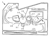
図1と図2に、本発明の現像ローラとしての弾性ローラに関する構造の一例を模式的に図示する。図1、2に例示の弾性ローラ1は、中心に軸芯体として、通常、金属などの導電性材料で形成される軸芯金11を有し、ローラ層として、軸芯金11の外周面上に弾性体層(基層)12が固定され、この弾性体層12の外周面に樹脂層(表層)13を積層した構造を有する。ここでは、上記のような軸芯体の外周面に二層で構成されてなる弾性ローラで説明する。
FIG. 1 and FIG. 2 schematically show an example of a structure relating to an elastic roller as a developing roller of the present invention. The
軸芯体11としては、円柱状または中空円筒状の形状を有し、金属などの導電性材料で形成される軸芯体を用いることができる。なお、かかる弾性ローラが電気的に絶縁された状態で利用される場合(例えば、加圧ローラや搬送ローラ)には、使用に際して、弾性ローラに加わる外力に対して、その軸芯体の形状を堅固に保持できる限り、軸芯体は非導電性材料で形成されていてもよい。また、かかる弾性ローラが電気的なバイアスを印加して、あるいは、接地されて、使用される場合であっても、軸芯体全体を導電性材料で構成する代わりに、主体は、非導電性材料で形成し、その表面に所望の導電性を満足する導電性処理、例えば、良導性の被覆層による被覆を施した構造のものを用いることもできる。
As the
電子写真装置に利用される現像ローラ、帯電ローラ、転写ローラは、電気的なバイアスを印加して、または、接地されて、使用されるのが一般的であるので、軸芯体を導電性の基体、所謂軸芯金11の形態とする。例えば、帯電ローラ用の弾性ローラでは、軸芯金11は、支持部材であることは勿論であるが、帯電部材の電極として機能するものであり、例えば、アルミニウム,銅合金,ステンレス鋼等の金属または合金、あるいは、クロム,ニッケル等で鍍金処理を施した鉄、合成樹脂など、少なくともその外周面は、その上に形成されるローラ層に所定の電圧を印加するに十分な導電性の材質で構成する。電子写真装置に利用される現像ローラ、帯電ローラ、転写ローラにおいては、軸芯体である導電性基体の外径は、通常4〜10mmの範囲とされる。
Since a developing roller, a charging roller, and a transfer roller used in an electrophotographic apparatus are generally used with an electrical bias applied or grounded, the shaft core body is electrically conductive. The substrate is a so-called
基層となる弾性体層12は柔軟性を有するものであり、原料主成分としてゴムを用いた成型体として形成したものを用いることができる。弾性体層12の原料主成分のゴムとしては、従来より弾性ローラに用いられている種々のゴムを用いることができる。具体的には、エチレン−プロピレン−ジエン共重合ゴム(EPDM)、アクリルニトリル−ブタジエンゴム(NBR)、クロロプレンゴム(CR)、天然ゴム(NR)、イソプレンゴム(IR)、スチレン−ブタジエンゴム(SBR)、フッ素ゴム、シリコーンゴム、エピクロロヒドリンゴム、NBRの水素化物、多硫化ゴム、ウレタンゴム等のゴム材料から選択して用いることができる。所望の弾性体硬度やローラにおける所望とする特性を与える限り、これらの材料は必要に応じて2種以上を組み合わせて用いてもよい。これらのゴム材料に種々の添加剤などを必要に応じて配合して弾性体層を成形することができる。添加剤としては、弾性ローラの個別的な用途に合わせて、弾性体層自体に要求される機能に必要な成分、例えば、導電剤、非導電性充填剤など、また、ゴム成型体とする際に利用される各種添加剤成分、例えば、架橋剤、触媒、分散促進剤など、各種の添加剤を主成分のゴム材料に適宜配合することができる。これらの添加量も、目的とする用途において要求される特性などに応じて選択することができる。
The
弾性体層に導電性を付与する目的に添加する、導電剤としては、カーボンブラック、グラファイト、アルミニウム、銅、錫、ステンレス鋼などの各種導電性金属、または合金、酸化錫、酸化亜鉛、酸化インジウム、酸化チタン、酸化錫―酸化アンチモン固溶体、酸化錫―酸化インジウム固溶体などの各種導電性金属酸化物、これらの導電性材料で被覆された絶縁性物質などの微粉末を用いることができる。これらの内、カーボンブラックは、比較的容易に入手でき、また、主成分のゴム材料の種類に依らず、良好な帯電性が得られるため、好適に利用できる。主成分のゴム材料中に、微粉末状の導電剤を分散させる手段としては、従来から利用される手段、例えば、ロールニーダー、バンバリーミキサー、ボールミル、サンドグラインダー、ペイントシェーカーなどを、主成分のゴム材料に応じて適宜利用すればよい。 The conductive agent added for the purpose of imparting conductivity to the elastic layer includes various conductive metals such as carbon black, graphite, aluminum, copper, tin, and stainless steel, or alloys, tin oxide, zinc oxide, and indium oxide. Further, various conductive metal oxides such as titanium oxide, tin oxide-antimony oxide solid solution, tin oxide-indium oxide solid solution, and fine powders such as insulating substances coated with these conductive materials can be used. Among these, carbon black can be suitably used because it can be obtained relatively easily and good chargeability can be obtained regardless of the type of the main rubber material. As a means for dispersing the finely powdered conductive agent in the main rubber material, conventionally used means such as a roll kneader, a Banbury mixer, a ball mill, a sand grinder, a paint shaker, etc. may be used. What is necessary is just to use suitably according to material.
その他、弾性体層に導電性を付与する手段として、導電剤に代えて、あるいは、導電剤とともに、導電性高分子化合物を添加する手法も利用できる。例えば、導電性高分子化合物としては、ホストポリマーとして、ポリアセチレン、ポリ(p−フェニレン)、ポリピロール、ポリチオフェニン、ポリ(p−フェニレンオキシド)、ポリ(p−フェニレンスルフィド)、ポリ(p−フェレンビニレン)、ポリ(2,6−ジメチルフェニレンオキサイド)、ポリ(ビスフェノールAカーボネート)、ポリビニルカルバゾール、ポリジアセチレン、ポリ(N−メチル−4−ビニルピリジン)、ポリアニリン、ポリキノリン、ポリ(フェニレンエーテルスルフォン)などを使用し、これらにドーパントして、AsF5、I2、Br2、SO3、Na、K、ClO4、FeCl3、F、Cl、Br、I、Kr等の各イオン、Li、TCNQ(7,7,8,8−テトラシアノキノジメタン)等をドープしたものが利用できる。 In addition, as a means for imparting conductivity to the elastic layer, a method of adding a conductive polymer compound instead of the conductive agent or together with the conductive agent can be used. For example, as a conductive polymer compound, as a host polymer, polyacetylene, poly (p-phenylene), polypyrrole, polythiophenine, poly (p-phenylene oxide), poly (p-phenylene sulfide), poly (p-ferene vinylene) ), Poly (2,6-dimethylphenylene oxide), poly (bisphenol A carbonate), polyvinylcarbazole, polydiacetylene, poly (N-methyl-4-vinylpyridine), polyaniline, polyquinoline, poly (phenylene ether sulfone), etc. These are used as dopants, such as AsF 5 , I 2 , Br 2 , SO 3 , Na, K, ClO 4 , FeCl 3 , F, Cl, Br, I, Kr, and other ions, Li, TCNQ (7 , 7,8,8-tetracyanoquinodimethane) What is available.
ゴム成型体中に添加可能な非導電性充填剤としては、珪藻土、石英粉末、乾式シリカ、湿式シリカ、酸化チタン、酸化亜鉛、アルミノケイ酸、炭酸カルシウム等を挙げることができる。 Examples of the non-conductive filler that can be added to the rubber molded body include diatomaceous earth, quartz powder, dry silica, wet silica, titanium oxide, zinc oxide, aluminosilicate, calcium carbonate, and the like.
ゴム成型体を作製する際に利用される、架橋剤としては、ジ−t−ブチルパーオキサイド、2,5−ジメチル−2,5−ジ(t−ブチルパーオキシ)ヘキサン、ジクミルパーオキサイド、t−ブチルパーオキシベンゾエート、p−クロロベンゾイルパーオキサイドなどを挙げることができる。例えば、液状シリコーンゴムを用いる際には、ポリオルガノハイドロジェンシロキサンを架橋成分として、白金系触媒を用いて、ゴム成分相互の架橋が図られる。 As a crosslinking agent used when producing a rubber molded body, di-t-butyl peroxide, 2,5-dimethyl-2,5-di (t-butylperoxy) hexane, dicumyl peroxide, Examples thereof include t-butyl peroxybenzoate and p-chlorobenzoyl peroxide. For example, when liquid silicone rubber is used, the rubber components can be cross-linked using a platinum catalyst with polyorganohydrogensiloxane as a cross-linking component.
なお、弾性ローラを現像ローラとして用いる場合は、当接する際に均一なニップ幅を確保し、かつ、好適なセット回復性を満たすためには、弾性体層の厚さは、好ましくは、0.5mm以上、より好ましくは、1.0mm以上とすることが望ましい。なお、作製される弾性ローラの外径精度を損なわない限り、弾性体層の厚さに特に制限はないものの、一般に、弾性体層の厚さを過度に厚くすると、ゴム成型体の作製コストを適正な範囲に抑えることが難しく、これらの実用上の制約を考慮すると、弾性体層の厚さは、好ましくは6.0mm以下、より好ましくは5.0mm以下とすることが望ましい。従って、弾性体層の厚さは、0.5〜6.0mmの範囲に選択する構成とすることが望ましく、1.0〜5.0mmの範囲に選択する構成とすることがより望ましい。また、弾性体層の厚さは、その硬度に応じて適宜選択されるものである。 In the case where an elastic roller is used as the developing roller, the thickness of the elastic layer is preferably 0. In order to ensure a uniform nip width when abutting and to satisfy a suitable set recoverability. It is desirable that the thickness is 5 mm or more, more preferably 1.0 mm or more. The thickness of the elastic body layer is not particularly limited as long as the outer diameter accuracy of the produced elastic roller is not impaired, but generally, if the thickness of the elastic body layer is excessively increased, the production cost of the rubber molded body is reduced. In view of these practical restrictions, the thickness of the elastic body layer is preferably 6.0 mm or less, more preferably 5.0 mm or less. Therefore, the thickness of the elastic layer is desirably selected in the range of 0.5 to 6.0 mm, and more desirably selected in the range of 1.0 to 5.0 mm. The thickness of the elastic body layer is appropriately selected according to the hardness.
弾性体層12の硬度(Asker-C)は、10〜70°の範囲に選択する。硬度(Asker-C)が、10°未満では、ゴム弾性が得られ難くなり、一方、70°を超える場合には、適切なニップ幅を得ることが難しくなってしまう傾向にある。より好ましくは、弾性体層を形成するゴム成型体の硬度(Asker-C)は、15〜55°の範囲に選択することが望ましい。
The hardness (Asker-C) of the
表層となる樹脂層11は、ウレタン樹脂を含有する樹脂層であり、樹脂成分中に糖アルコール及び糖アルコール由来の成分の少なくとも1種を含む。樹脂成分中に含有される糖アルコール及び糖アルコール由来の成分(複数種を用いる場合はそれらの合計量)は、0.050〜5.0質量%の範囲にあるのが適当である。含有量が0.050質量%未満では、添加による効果を得るには十分でなく、表層表面の付着性低減や、表層被膜の強度向上が得られない。一方、含有量が5.0質量%を超えると、ベースとなるウレタン樹脂の柔軟性を損ない硬くなるため、ひび割れ等が発生して不具合が生じる。また、キシリトールを添加する場合には、0.40〜4.0質量%の範囲がより好ましい。ここで糖アルコールの質量百分率を求める際の、「樹脂成分」とは、ウレタン樹脂のポリオール、ジイソシアネート、他樹脂とのブレンドの場合は、その樹脂やそのモノマー成分、硬化剤成分、架橋剤成分などの樹脂そのものやそれを構成する成分で樹脂層の被膜形成成分として主体をなす成分(糖アルコールを含む)を基準とし、導電剤、非導電性充填剤などの添加剤は、含まないものとする。
The
また、糖アルコール由来する成分とは、糖アルコールの炭素原子および酸素原子の構成が維持された状態を意味するものとする。例えば、糖アルコールの水酸基(−OH)有する炭素が、架橋材として用いられるイソシアネート化合物との間に、ウレタン結合を形成したの構成などを指す。具体的には、糖アルコールであるキシリトール(下記式(1)参照)に対し、キシリトール由来の構造(成分)は、下記式(2)に示したものなどがあげられる。 Moreover, the component derived from sugar alcohol shall mean the state by which the structure of the carbon atom and oxygen atom of sugar alcohol was maintained. For example, the structure which the carbon which the hydroxyl group (-OH) of sugar alcohol has formed the urethane bond between the isocyanate compound used as a crosslinking material points out. Specifically, the xylitol-derived structure (component) with respect to xylitol, which is a sugar alcohol (see the following formula (1)), includes those shown in the following formula (2).

以下に、水酸化ナトリウムによる分解方法の手順を以下に示す。試料1g程度を細かく切り、20質量%水酸化ナトリウム20mlとともに加圧分解容器に入れ、180℃で12時間分解する。冷却後ジエチルエーテルで抽出し、エーテル層をさらに2N塩酸で洗う。エーテル層にはポリエーテルポリオールや、糖アルコール、塩酸水溶液中にイソシアネート由来のジアミン、アルカリ分解液中には鎖延長剤(ジイソシアネート他)が含まれており、13C NMR,1H NMR,IRなどにより成分の同定を行う。ポリエステルポリオールの場合には、ジオール化合物とジカルボン酸に分解されるのでこれを同様に分析し成分の同定を行う。 The procedure of the decomposition method using sodium hydroxide is shown below. About 1 g of a sample is cut finely, put into a pressure decomposition vessel together with 20 ml of 20% by mass sodium hydroxide, and decomposed at 180 ° C. for 12 hours. After cooling, the mixture is extracted with diethyl ether, and the ether layer is further washed with 2N hydrochloric acid. The ether layer contains polyether polyol, sugar alcohol, diamine derived from isocyanate in aqueous hydrochloric acid, and chain extender (diisocyanate, etc.) in the alkaline decomposition solution. 13 C NMR, 1 H NMR, IR, etc. The component is identified by In the case of polyester polyol, it is decomposed into a diol compound and a dicarboxylic acid, and this is analyzed in the same manner to identify components.
また、ピリジンによる分解方法に関しては、米森重明らの文献(分析化学、41、655、1992)に示されている方法を用いることが出来、ポリエステルポリオールの分子量測定や鎖延長剤との区別が出来る。上記の方法等を用いて、糖アルコールまたは糖アルコール由来の構成の質量%を求めることが出来る。 As for the decomposition method using pyridine, the method described in Shigeaki Yonemori et al. (Analytical Chemistry, 41, 655, 1992) can be used, and the molecular weight measurement of the polyester polyol and the chain extender can be distinguished. . By using the above method or the like, the sugar mass or the mass% of the sugar alcohol-derived constitution can be determined.
糖アルコールとしては、1分子中に4個以上の水酸基を有するものが好ましく、アドニトール、アラビトール、キシリトール、D-マンニトール、イジトール、タリトール、ズルシトール、マルチトール、ラクチトール、ペンタエリスリトール、メチルグルコシドなどで、これらは単独で用いても混合して用いてもよい。この中でも、単糖類の糖アルコールが用い易く、かつ効果が顕著で安定している。特に、キシリトール、D-マンニトールがより好ましい。単糖類を用いた場合には、分子量が低く樹脂溶液での運動性が高く、かつ立体障害が少ない等の理由により、効率的に高次架橋構造を得られ易いものと考えられる。また、同じ単糖類であるD-ソルビトールは保湿性に優れた性質を持っており、本発明においては扱い難く、効果も不十分であり、好ましく用いられない。ウレタン樹脂硬化の反応は水分の影響を受け易く、D-ソルビトールの含有水分量(または、その水分量のバラツキ)等が影響しているものと考えられる。 As the sugar alcohol, those having 4 or more hydroxyl groups in one molecule are preferable, such as adonitol, arabitol, xylitol, D-mannitol, iditol, thalitol, dulcitol, maltitol, lactitol, pentaerythritol, methyl glucoside, etc. May be used alone or in combination. Among these, monosaccharide sugar alcohols are easy to use, and the effects are remarkable and stable. In particular, xylitol and D-mannitol are more preferable. When a monosaccharide is used, it is considered that it is easy to efficiently obtain a high-order crosslinked structure for reasons such as low molecular weight, high mobility in a resin solution, and low steric hindrance. Further, D-sorbitol, which is the same monosaccharide, has a property excellent in moisture retention, is difficult to handle in the present invention, has insufficient effects, and is not preferably used. The reaction of urethane resin curing is easily affected by moisture, and it is considered that the moisture content of D-sorbitol (or variation in the moisture content) is affected.
この樹脂層(表層)13を形成する被膜の主成分は、ウレタン樹脂が用いられる。例えば、現像ローラの用途では、ウレタン樹脂を用いた場合、トナー帯電性、自己膜補強性、柔軟性を合わせ持つ被膜が得られやすい。 A urethane resin is used as a main component of the film forming the resin layer (surface layer) 13. For example, in the use of a developing roller, when urethane resin is used, it is easy to obtain a film having both toner chargeability, self-film reinforcement, and flexibility.
利用可能なウレタン樹脂の樹脂膜体としては、例えば、ポリウレタンプレポリマーを架橋反応させる方法で作製したもの、あるいは、ポリオールに添加剤の導電性材料を予め配合し、この配合物中のポリオールを、ワン・ショット法にてポリイソシアネートと反応させ、ポリウレタン樹脂とする方法で作製されるものなどが挙げられる。 As a resin film body of a urethane resin that can be used, for example, one prepared by a method of cross-linking a polyurethane prepolymer, or a conductive material of an additive is previously blended with a polyol, and the polyol in this blend is Examples include those prepared by reacting with polyisocyanate by a one-shot method to obtain a polyurethane resin.
このワン・ショット法にてポリウレタン樹脂を作製する際には、用いるポリオールとしては、一般の軟質ポリウレタンフォームやウレタンエラストマー製造に用いられるポリオール、例えば、末端にポリヒドロキシル基を有するポリエーテルポリオール、ポリエステルポリオール、ならびに、両者の共重合物であるポリエーテルポリエステルポリオールが挙げられる。その他に、ポリブタジエンポリオールやポリイソプレンポリオール等のポリオレフィンポリオール、ポリオール中でエチレン性不飽和単量体を重合させて得られる所謂ポリマーポリオール等の一般的なポリオールを使用することもできる。 When a polyurethane resin is produced by this one-shot method, the polyol used is a polyol used for producing a general flexible polyurethane foam or urethane elastomer, for example, a polyether polyol having a polyhydroxyl group at the terminal, a polyester polyol. And polyether polyester polyol which is a copolymer of both. In addition, general polyols such as polyolefin polyols such as polybutadiene polyol and polyisoprene polyol, and so-called polymer polyols obtained by polymerizing ethylenically unsaturated monomers in polyols can also be used.
一方、前記のポリオール化合物と反応させるイソシアネート化合物としては、一般的な軟質ポリウレタンフォームやウレタンエラストマー製造に使用されるポリイソシアネート、即ち、トリレンジイソシアネート(TDI)、粗製TDI、4,4′−ジフェニルメタンジイソシアネート(MDI)、粗製MDI、炭素数2〜18の脂肪族ポリイソシアネート、炭素数4〜15の脂環式ポリイソシアネート及びこれらポリイソシアネートの混合物やその変性物、例えば、部分的にポリオール類と反応させて得られるプレポリマー等が用いられる。 On the other hand, as the isocyanate compound to be reacted with the above-mentioned polyol compound, polyisocyanate used for production of general flexible polyurethane foam and urethane elastomer, that is, tolylene diisocyanate (TDI), crude TDI, 4,4'-diphenylmethane diisocyanate. (MDI), crude MDI, aliphatic polyisocyanates having 2 to 18 carbon atoms, alicyclic polyisocyanates having 4 to 15 carbon atoms, mixtures of these polyisocyanates and modified products thereof, for example, partially reacted with polyols The prepolymer obtained by the above is used.
また、その他の成分、例えばブレンドする成分等について特に限定されるものではないが、例えば、現像ローラとして用いる場合に、現像剤としてのトナー粒子を担持する機能を考慮すると、自己膜補強性、トナー帯電性等の観点から、ウレタン樹脂に加えて、ポリアミド樹脂、ウレア樹脂も好ましく用いられる。なお、ウレタン樹脂以外の樹脂の配合比は、ウレタン樹脂の性質を損なわない範囲で、樹脂成分中に、2〜20質量%の範囲で用いることが好ましい。 The other components, for example, the components to be blended are not particularly limited. For example, when used as a developing roller, considering the function of supporting toner particles as a developer, self-film reinforcing property, toner From the viewpoint of chargeability and the like, in addition to the urethane resin, a polyamide resin and a urea resin are also preferably used. In addition, it is preferable to use the compounding ratio of resin other than a urethane resin in the range of 2-20 mass% in a resin component in the range which does not impair the property of a urethane resin.
更に、表層としての樹脂層13を成膜性よく形成するために、弾性ローラの個別的な用途に合わせて、樹脂層自体に要求される機能に必要な成分、例えば、導電剤、非導電性充填剤など、また、弾性層12の外周に成膜積層する際に利用される各種添加剤成分、例えば、架橋剤、触媒、分散促進剤など、各種の添加剤を主成分の樹脂材料に適宜配合することができる。なお、導電剤、非導電性充填剤などの添加剤は、先に弾性体層に含有可能な添加剤として例示したものなどから、主成分の樹脂材料に応じて、適宜選択することができる。また、その添加量は、形成される樹脂層の特性を本発明の効果を発揮する範囲内に維持する限り、添加目的に応じて、適宜選択することができる。
Furthermore, in order to form the
樹脂層13の弾性率は、被膜性、耐久性が実用上得られれば、特に制限されることはない。樹脂層13は、弾性体層12の変形に対する高い追従性を示すことが望まれ、従って、樹脂層を形成する樹脂膜体の硬度および弾性率は低い方が好ましい。
The elastic modulus of the
なお、樹脂層13の厚さは、十分な耐摩耗性を確保するために、3μm以上に選択することが好ましい。一方、現像ローラ、帯電ローラ、転写ローラなどでは、導電性を有する弾性ローラとされ、その際、均一な導電性を実現するために、樹脂層の厚さは、100μm以下に留めることが好ましい。また、樹脂層の厚さを、3μm未満とする場合には、弾性体層表面に所望の薄い膜厚では均一に塗布・形成することが難しく、一方、樹脂層の硬度は、弾性体層の硬度より高いため、100μmを超える膜厚とすると、弾性ローラ全体の変形性に対する影響が大きくなり好ましくない。また、樹脂層の厚さは、上記の範囲でその硬度等に応じて適宜選択されればよい。本発明の樹脂層の厚さは、ローラより切り出したサンプルにより、断面を光学顕微鏡等により観察することにより測定し求めたものである。
The thickness of the
樹脂層13の形成には、樹脂膜体の原料となる樹脂原料を液状として、弾性体層表面に塗布し、その後、樹脂膜体とする方法を利用することができる。この樹脂原料の塗布方法は、特に限定されないが、エアスプレー、ロールコート、カーテンコート、ディッピング等の方法により、樹脂原料を所望の厚さで、弾性体層表面に均一に塗布する。その後、樹脂膜体とするため、必要に応じ、加熱処理を行う場合がある。
For forming the
以上、弾性体層12及び樹脂層13を軸芯体11上にこの順に積層した2層構造の弾性ローラについて説明したが、本発明にかかる弾性ローラにおける軸芯体外周上の層構成は3層以上の多層構成を有するものであってもよい。例えば、図2に示す構成における弾性体層12と樹脂層13の間に、別の樹脂層を更に設けた弾性ローラや、弾性体層12自体が複数の層(例えば、3つの弾性層が順次積層された構成)で構成される弾性ローラがあげられる。どのような構成においても、最外層としての表層(樹脂層13)の機能が十分に得られる、つまり、本発明の効果が得られれば問題はない。
The two-layered elastic roller in which the
以上に説明した様に、本発明の弾性ローラは、最も外側に位置する表層として被覆された樹脂層において、ウレタン樹脂の持つ柔軟性や変形追従性、セット性を維持したまま、糖アルコール添加により、被膜層の付着性を低減し、被膜の強度を向上し優れた耐久性を持つものとなる。この利点から、本発明の弾性ローラは、電子写真装置等における、現像ローラ、帯電ローラ、転写ローラ等の弾性ローラとして好適に使用できる。特に、現像ローラに用いた場合には、柔軟なウレタン樹脂層を用いることで適切なニップ幅が得られ易いと同時に、表面への現像剤成分の固着等が生じず、適正な量の現像剤をその表面に薄膜化して担持した状態で感光体と密に圧接することが可能となり、感光体表面に適量の現像剤を均一に付与し、より良好な画像形成を行うことができ、なおかつ、その被膜強度が高く優れた耐久性により、その良好な画像品質を長期にわたる使用後も維持できる。更に、利用される電子写真装置自体、高速化され、プロセス速度、すなわち、感光体表面の速度が増す条件において、前記の利点は一層顕著なものとなる。 As described above, the elastic roller according to the present invention is obtained by adding sugar alcohol while maintaining the flexibility, deformation followability, and setability of the urethane resin in the resin layer coated as the outermost surface layer. The adhesion of the coating layer is reduced, the strength of the coating is improved, and the durability is excellent. From this advantage, the elastic roller of the present invention can be suitably used as an elastic roller such as a developing roller, a charging roller, and a transfer roller in an electrophotographic apparatus or the like. In particular, when used for a developing roller, it is easy to obtain an appropriate nip width by using a flexible urethane resin layer, and at the same time, the developer component does not stick to the surface, and an appropriate amount of developer. Can be in close contact with the photoconductor in a state where it is carried as a thin film on its surface, uniformly applying an appropriate amount of developer to the surface of the photoconductor, and performing better image formation, and Due to its high coating strength and excellent durability, its good image quality can be maintained after long-term use. Further, the above-described advantages become more remarkable under the condition that the electrophotographic apparatus to be used is speeded up and the process speed, that is, the speed of the surface of the photoreceptor is increased.
図3は、本発明の弾性ローラを現像ローラとして用いた現像装置、および弾性ローラを現像ローラ、帯電ローラ、あるいは転写ローラの少なくとも1つ以上として用いた画像形成装置の概略構成を示す断面図である。 FIG. 3 is a cross-sectional view showing a schematic configuration of a developing device using the elastic roller of the present invention as a developing roller, and an image forming apparatus using the elastic roller as at least one of a developing roller, a charging roller, or a transfer roller. is there.
この画像形成装置では、潜像担持体としての感光ドラム21が矢印A方向に回転し、感光ドラム21を帯電処理するための帯電装置22によってそこを通過した感光ドラム21の領域が一様に帯電され、更にこの帯電領域において、静電潜像を書き込む露光手段であるレーザー光23により、その表面に静電潜像が形成される。静電潜像は、感光ドラム21に対して近接配置され、画像形成装置本体に対し着脱可能なプロセスカートリッジ24(図示せず)に保持される現像装置2によって現像剤たるトナーを付与されることにより現像され、トナー像として可視化(顕在化)される。
In this image forming apparatus, the photosensitive drum 21 as a latent image carrier rotates in the direction of arrow A, and the region of the photosensitive drum 21 that has passed therethrough is uniformly charged by the charging
現像には、露光部にトナー像を形成するいわゆる反転現像などの方式が利用できる。可視化された感光ドラム21上のトナー像(画像)は、転写ローラ29によって紙などの転写紙33に転写される。トナー像を転写された紙33は、定着装置32により定着処理され、装置外に排紙されプリント動作が終了する。転写ローラ33は、感光ドラム21のトナー像を保持する領域に、転写紙33をその裏面から押当てて、トナー像を転写紙の表面に転写させるもので、感光ドラムのトナー像を保持する領域と逆に帯電していることで、トナー像の転写が促進される。転写紙33の感光ドラム21の表面への押し当ては、感光ドラム21と転写ローラ29とが接触している部分に、これらの回転に伴って、転写紙33が自動的に挿入されることにより達成される。
For development, a method such as so-called reversal development in which a toner image is formed on the exposed portion can be used. The visualized toner image (image) on the photosensitive drum 21 is transferred onto a transfer paper 33 such as paper by a
一方、転写されずに感光ドラム上21上に残存した転写残トナーはクリーニングブレード30により掻き取られ廃トナー容器31に収納され、クリーニングされた感光ドラム21に対して上記のプロセスを繰り返すことで、同一画像のコピーや、新たな画像の転写を行なうことができる。 On the other hand, the transfer residual toner remaining on the photosensitive drum 21 without being transferred is scraped off by the cleaning blade 30 and stored in the waste toner container 31, and the above process is repeated on the cleaned photosensitive drum 21. The same image can be copied or a new image can be transferred.
図示した例では、現像装置2は、一成分現像剤として非磁性トナー28を収容した現像装置34と、現像容器34内の長手方向に延在する開口部に位置し感光ドラム21と対向設置された現像剤担持体としての現像ローラ25とを備え、感光ドラム21上の静電潜像を現像して可視化するようになっている。
In the illustrated example, the developing
尚、現像ローラ25は感光ドラム21と当接幅をもって接触している。現像装置2においては、弾性を有する補助ローラ26が、現像容器34内で、弾性ブレード27の現像ローラ25表面との当接部に対し現像ローラ25回転方向上流側に当接され、かつ、回転可能に支持されている。補助ローラ26の構造としては、発泡骨格状スポンジ構造や芯金上にレーヨン、ナイロン等の繊維を植毛したファーブラシ構造のものが、現像ローラ25へのトナー28供給および未現像トナーの剥ぎ取りの点から好ましい。本実施形態においては、芯金上にポリウレタンフォームを設けた直径16mmの補助ローラ26を用いた。
The developing
この補助ローラ26の現像ローラ25に対する当接幅としては、1〜8mmが有効であり、また、現像ローラ25に対してその当接部において相対速度をもたせることが好ましく、本実施形態においては、当接幅を3mmに設定し、弾性ローラ26の周速として現像動作時に50mm/s(現像ローラ25との相対速度は130mm/s)となるように駆動手段(図示せず)により所定タイミングで回転駆動させている。
As the contact width of the auxiliary roller 26 with respect to the developing
本発明にかかる弾性ローラは、感光ドラム21の表面のクリーニングされた領域に当接または圧接してこの領域を帯電するための帯電ローラ22や、感光体ドラム21のトナー像を保持する領域に当接または圧接して配置される転写ローラ29としても好適に利用できる。
The elastic roller according to the present invention is applied to a charging
以下に、実施例を示し、本発明をより具体的に説明する。これら実施例は、本発明における最良の実施形態の一例ではあるものの、本発明は、実施例によって、何ら限定されるものではない。実施例に示す手法で作製される弾性ローラは、例えば、現像ローラ等の現像部材、帯電ローラや転写ローラ等の帯電部材、これら各種の個別的な用途において、電子写真装置等で使用される弾性ローラとして好適に使用できる。
[実施例1]弾性ローラ1
軸芯体としてニッケル鍍金を施したSUS製の芯金(φ6mm)の外周面に、さらに接着剤を塗布、焼き付けしたものを用いた。この軸芯体を金型に配置し、原料ゴムとして、液状のシリコーンゴム(末端ビニル基封鎖の直鎖状ポリジメチルシロキサンと、1つのビニル基を有する分岐ポリシロキサンセグメントと、二官能性のジメチルシロキサンを有する直鎖状オイルセグメントとからなるブロックポリマーとからなるポリシロキサン混合物に、架橋剤として1分子中にケイ素結合水素原子を2個以上有したオルガノシロキサンと白金系触媒を加え、混合した付加型シリコーンゴム組成物)100質量部、無機微粉体である耐熱性付与剤としてシリカ粉体4質量部、石英粉末60質量部、導電性付与剤としてカーボンブラック10質量部を混合し、液状ゴムコンパウンドを調製しこれを金型内に形成されたキャビティに注入した。続いて、金型を150℃で20分間加熱してシリコーンゴムを加硫硬化し、冷却した後に脱型することで、厚み4mmの弾性体層を軸芯体の外周に設けたローラを作製した。
Hereinafter, the present invention will be described more specifically with reference to examples. These examples are examples of the best mode of the present invention, but the present invention is not limited to the examples. The elastic roller manufactured by the method shown in the embodiment is, for example, a developing member such as a developing roller, a charging member such as a charging roller or a transfer roller, and an elastic used in an electrophotographic apparatus or the like in various individual applications. It can be suitably used as a roller.
[Example 1]
An SUS metal core (φ6 mm) with nickel plating applied as a shaft core was further applied and baked with an adhesive. This shaft core is placed in a mold, and as a raw rubber, a liquid silicone rubber (a linear polydimethylsiloxane blocked with a terminal vinyl group, a branched polysiloxane segment having one vinyl group, and a bifunctional dimethyl group). Addition of a polysiloxane mixture consisting of a block polymer consisting of a linear oil segment containing siloxane and an organosiloxane having two or more silicon-bonded hydrogen atoms in one molecule as a cross-linking agent and a platinum-based catalyst Type silicone rubber composition) 100 parts by mass, 4 parts by mass of silica powder as a heat resistance imparting agent that is an inorganic fine powder, 60 parts by mass of quartz powder, and 10 parts by mass of carbon black as a conductivity imparting agent are mixed to form a liquid rubber compound. Was prepared and injected into a cavity formed in the mold. Subsequently, the mold was heated at 150 ° C. for 20 minutes to cure and cure the silicone rubber, and after cooling, the mold was removed to produce a roller having an elastic body layer having a thickness of 4 mm on the outer periphery of the shaft core body. .
次に、ポリオール(ニッポラン5025;商品名、日本ポリウレタン工業株式会社製)の固形分100質量部に対し、硬化剤としてイソシアネート(コロネートL;商品名、日本ポリウレタン工業株式会社製)の固形分15質量部、糖アルコールとしてキシリトール(キシリット;商品名、東和化成工業株式会社製)0.10質量部、導電剤としカーボンブラックを適量添加し、メチルエチルケトンを主溶剤として用い、十分に撹拌して、均一な固形分11%の有機溶剤混合溶液となるよう調整した。この塗料溶液中に、上記ローラを浸漬してコーティングした後、引上げて乾燥させ、142℃にて30分間加熱処理することで、約20μmの表面層を弾性体層の外周に設けた弾性ローラ1を作製した。このようにして作製した弾性ローラ1の表層の樹脂成分中の糖アルコール成分は、0.087質量%であった。
Next, solid content 15 mass of isocyanate (Coronate L; trade name, manufactured by Nippon Polyurethane Industry Co., Ltd.) as a curing agent with respect to 100 mass parts of solid content of polyol (Nipporan 5025; trade name, manufactured by Nippon Polyurethane Industry Co., Ltd.). Parts, xylitol as sugar alcohol (xylit; trade name, manufactured by Towa Kasei Kogyo Co., Ltd.) 0.10 parts by mass, carbon black as a conductive agent is added in an appropriate amount, methyl ethyl ketone is used as a main solvent, and the mixture is stirred thoroughly It adjusted so that it might become an organic solvent mixed solution of 11% of solid content. The roller is immersed in this coating solution, coated, pulled up, dried, and heat-treated at 142 ° C. for 30 minutes to provide an
[実施例2]弾性ローラ2
糖アルコール成分であるキシリトール(キシリット、東和化成工業株式会社製;商品名)の添加量を、0.50質量部に変更した以外は実施例1と同様にして弾性ローラ2を作製した。作製した弾性ローラ2の表層の樹脂成分中の糖アルコール成分は、0.43質量%であった。
[Example 2]
The
[実施例3]弾性ローラ3
糖アルコール成分であるキシリトール(キシリット、東和化成工業株式会社製;商品名)の添加量を、3.0質量部に変更した以外は実施例1と同様にして弾性ローラ3を作製した。作製した弾性ローラ3の表層の樹脂成分中の糖アルコール成分は、2.5質量%であった。
[Example 3]
The
[実施例4]弾性ローラ4
糖アルコール成分であるキシリトール(キシリット、東和化成工業株式会社製;商品名)の添加量を、4.7質量部に変更した以外は実施例1と同様にして弾性ローラ4を作製した。作製した弾性ローラ4の表層の樹脂成分中の糖アルコール成分は、3.9質量%であった。
[実施例5]弾性ローラ5
糖アルコール成分であるキシリトール(キシリット、東和化成工業株式会社製;商品名)の添加量を、5.8質量部に変更した以外は実施例1と同様にして弾性ローラ5を作製した。作製した弾性ローラ5の表層の樹脂成分中の糖アルコール成分は、4.8質量%であった。
[Embodiment 4] Elastic roller 4
The elastic roller 4 was produced in the same manner as in Example 1 except that the addition amount of xylitol (Xylit, manufactured by Towa Kasei Kogyo Co., Ltd .; trade name), which is a sugar alcohol component, was changed to 4.7 parts by mass. The sugar alcohol component in the resin component of the surface layer of the produced elastic roller 4 was 3.9% by mass.
[Embodiment 5] Elastic roller 5
The elastic roller 5 was produced in the same manner as in Example 1 except that the amount of xylitol (Xylit, manufactured by Towa Kasei Kogyo Co., Ltd .; trade name), which is a sugar alcohol component, was changed to 5.8 parts by mass. The sugar alcohol component in the resin component of the surface layer of the produced elastic roller 5 was 4.8% by mass.
[実施例6]弾性ローラ6
糖アルコール成分として、キシリトールに代えて、D−マンニトール(マリンクリスタル、東和化成工業株式会社製;商品名)1.2質量部を添加した以外は実施例1と同様にして弾性ローラ6を作製した。作製した弾性ローラ6の表層の樹脂成分中の糖アルコール成分は、1.0質量%であった。
[Embodiment 6]
An
[実施例7]弾性ローラ7
糖アルコール成分として、キシリトールに代えて、D−マンニトール(マリンクリスタル、東和化成工業株式会社製;商品名)3.0質量部を添加した以外は実施例1と同様にして弾性ローラ7を作製した。作製した弾性ローラ7の表層の樹脂成分中の糖アルコール成分は、2.5質量%であった。
[Embodiment 7] Elastic roller 7
An elastic roller 7 was produced in the same manner as in Example 1 except that 3.0 parts by mass of D-mannitol (Marine Crystal, manufactured by Towa Kasei Kogyo Co., Ltd .; trade name) was added as a sugar alcohol component instead of xylitol. . The sugar alcohol component in the resin component of the surface layer of the produced elastic roller 7 was 2.5% by mass.
[実施例8]弾性ローラ8
糖アルコール成分として、キシリトールに代えて、マルチトール(レシス、東和化成工業株式会社製;商品名)3.0質量部を添加した以外は実施例1と同様にして弾性ローラ8を作製した。作製した弾性ローラ8の表層の樹脂成分中の糖アルコール成分は、2.5質量%であった。
[Embodiment 8] Elastic roller 8
An elastic roller 8 was produced in the same manner as in Example 1 except that 3.0 parts by mass of maltitol (Resis, manufactured by Towa Kasei Kogyo Co., Ltd .; trade name) was added as a sugar alcohol component instead of xylitol. The sugar alcohol component in the resin component of the surface layer of the produced elastic roller 8 was 2.5% by mass.
[比較例1]弾性ローラ9
糖アルコール成分を添加しなかった以外は、実施例1と同様にして弾性ローラ9を作製した。作製した弾性ローラ9の表層の樹脂成分中に、糖アルコール成分は含まれていない。
[Comparative Example 1] Elastic roller 9
An elastic roller 9 was produced in the same manner as in Example 1 except that the sugar alcohol component was not added. The sugar alcohol component is not contained in the resin component of the surface layer of the produced elastic roller 9.
[比較例2]弾性ローラ10
糖アルコール成分であるキシリトール(キシリット、東和化成工業株式会社製;商品名)の添加量を、0.04質量部に変更した以外は実施例1と同様にして弾性ローラ10を作製した。作製した弾性ローラ10の表層の樹脂成分中の糖アルコール成分は、0.035質量%であった。
[Comparative Example 2] Elastic roller 10
The elastic roller 10 was produced in the same manner as in Example 1 except that the addition amount of xylitol (Xylit, manufactured by Towa Kasei Kogyo Co., Ltd .; trade name), which is a sugar alcohol component, was changed to 0.04 parts by mass. The sugar alcohol component in the resin component of the surface layer of the produced elastic roller 10 was 0.035% by mass.
[比較例3]弾性ローラ11
糖アルコール成分であるキシリトール(キシリット、東和化成工業株式会社製;商品名)の添加量を、10質量部に変更した以外は実施例1と同様にして弾性ローラ11を作製した。作製した弾性ローラ11の表層の樹脂成分中の糖アルコール成分は、8.0質量%であった。
[Comparative Example 3]
The
[特性の評価]
以上の様にして得られた弾性ローラを現像ローラとして実機に組み込み、各種の評価を行った。なお、すべての現像ローラの弾性体層および樹脂層には、適宜カーボンブラックを添加し、ローラの電気抵抗が106以下になるように調整した。
・付着性の評価
付着性の評価は、100枚プリント後の現像ローラを取り出し、そのローラ表面をエアスプレーにて空気を吹き付け、表面に付着している現像剤を飛散させ、さらにその表面をメチルアルコールを含んだ布で清拭し評価した。エアスプレーによる吹き付けでローラ表面がきれいに露出し付着物のないものを◎、現像剤に含まれる外添剤等の付着が少し見られるものを○、エアスプレーによる吹き付けでは付着物を除けないが、メチルアルコールを含んだ布で清拭するとローラ表面がきれいに露出するものを△、エアスプレーによる吹き付け、メチルアルコールを含んだ布で清拭のいずれでも付着物の残るものを×とした。
・画像レベル評価
画像レベルおよび耐久性の評価は、初期および6000枚プリント前後における画像上の問題の有無およびその変化、6000枚プリント後のローラ表面状態を観察して判断した。初期、6000枚プリント前後の画像自体の評価は、良好なものを◎、問題がないものを〇、やや濃淡が確認されるものを△、ボタ落ち等の著しい画像不良が確認されるものを×とした。耐久性の評価は、初期および6000枚プリント前後における画像を比較し、経時での変化がなく、いずれも良好もしくは問題のないものを◎、やや低下するが問題のないものを○、経時での変化はないが、画像そのものに問題あるものを△、経時により画像に問題が発生したものを×とした。
・総合評価
以上、総合評価としては、付着性、耐久性に問題がなく、かつ画像レベルが良好なものを◎、付着性、耐久性、画像レベルいずれにも問題がないものを〇、付着性、耐久性のいずれかに問題の生じたものを×とした。
[Characteristic evaluation]
The elastic roller obtained as described above was incorporated into an actual machine as a developing roller, and various evaluations were performed. In addition, carbon black was appropriately added to the elastic body layer and the resin layer of all the developing rollers, and the electric resistance of the rollers was adjusted to 10 6 or less.
・ Evaluation of adhesion The evaluation of adhesion was made by taking out the developing roller after printing 100 sheets, blowing the air on the roller surface with air spray, scattering the developer adhering to the surface, and further methylating the surface. Wipe with a cloth containing alcohol and evaluate. If the roller surface is clearly exposed by spraying with air spray and there is no deposit ◎, if there is a little adhesion of external additives contained in the developer ○, spraying by air spray can not remove the deposit, When the cloth containing methyl alcohol was wiped, the surface where the roller surface was clearly exposed was indicated by Δ, and when spraying with air spray and wiping with the cloth containing methyl alcohol were left as adhered, x was assigned.
Image Level Evaluation Image level and durability were evaluated by observing the presence and change of image problems at the initial stage and before and after printing 6000 sheets, and the state of the roller surface after printing 6000 sheets. Initially, the evaluation of the images before and after printing 6000 sheets was: ◎ for good, ◯ for no problem, △ for slightly shaded, and for those with noticeable image defects such as dropout × It was. The durability was evaluated by comparing the images at the initial stage and before and after printing of 6000 sheets. No change over time, ◎ for those that are good or no problem, ◯ for those that are slightly degraded but no problem, Although there was no change, the case where there was a problem in the image itself was indicated by Δ, and the case where the problem occurred in the image over time was indicated by ×.
・ Comprehensive evaluation As described above, the comprehensive evaluation is ◎ if there is no problem in adhesion and durability and the image level is good, ○ if there is no problem in any of the adhesion, durability, and image level. The case where a problem occurred in any of the durability was evaluated as x.
上記の基準に基づき評価した結果を、表1に示した。 The results of evaluation based on the above criteria are shown in Table 1.
図1の断面図である。
1…弾性ローラ
2…現像装置
3…画像形成装置
11…軸芯体
12…弾性体層(基層)
13…樹脂層(表層)
21…感光ドラム
22…帯電装置
23…レーザー光
25…現像ローラ
26…補助ローラ
27…弾性ブレード
28…トナー
29…転写ローラ
30…クリーニングブレード
31…廃トナー容器
32…定着装置
33…紙
34…現像容器
DESCRIPTION OF
13 ... Resin layer (surface layer)
21 ...
Claims (6)
最外層としての表層が、主成分としてウレタン樹脂を含む樹脂層からなり、かつ、該樹脂層の樹脂成分中に糖アルコールまたは該糖アルコールに由来する成分を0.050〜5.0質量%含有することを特徴とする現像ローラ。 A developing roller having a shaft core and two or more layers including an elastic layer provided on an outer peripheral surface of the shaft core,
The outermost surface layer is composed of a resin layer containing a urethane resin as a main component, and 0.05 to 5.0% by mass of sugar alcohol or a component derived from the sugar alcohol in the resin component of the resin layer A developing roller.
前記現像ローラが請求項1乃至4のいずれかに記載の現像ローラである
ことを特徴とする現像装置。 A latent image carrier for forming an electrostatic latent image by an electrophotographic method, and a developer in a state where the developer is carried in contact with or pressed against the surface of the latent image carrier. A developing roller for supplying the electrostatic latent image formed on the image carrier and developing the electrostatic latent image,
A developing device wherein the developing roller is characterized <br/> it is a developing roller according to any one of claims 1 to 4.
前記現像装置が、請求項5に記載の現像装置であることを特徴とする画像形成装置。 A latent image carrier capable of forming an electrostatic latent image by an electrophotographic method, a charging device for charging the latent image carrier for forming an electrostatic latent image, and a static region in a charged region of the latent image carrier. An electrostatic latent image forming apparatus for forming an electrostatic latent image; and a developer is attached to a region of the latent image carrier on which the electrostatic latent image is formed to visualize the electrostatic latent image. In an image forming apparatus having a developing device for obtaining an image and a transfer device for transferring an image made of the developer onto transfer paper,
An image forming apparatus according to claim 5 , wherein the developing device is the developing device according to claim 5.
Priority Applications (1)
| Application Number | Priority Date | Filing Date | Title |
|---|---|---|---|
| JP2004179906A JP4194533B2 (en) | 2004-06-17 | 2004-06-17 | Developing roller and image forming apparatus using the same |
Applications Claiming Priority (1)
| Application Number | Priority Date | Filing Date | Title |
|---|---|---|---|
| JP2004179906A JP4194533B2 (en) | 2004-06-17 | 2004-06-17 | Developing roller and image forming apparatus using the same |
Publications (3)
| Publication Number | Publication Date |
|---|---|
| JP2006003629A JP2006003629A (en) | 2006-01-05 |
| JP2006003629A5 JP2006003629A5 (en) | 2007-08-02 |
| JP4194533B2 true JP4194533B2 (en) | 2008-12-10 |
Family
ID=35772065
Family Applications (1)
| Application Number | Title | Priority Date | Filing Date |
|---|---|---|---|
| JP2004179906A Expired - Fee Related JP4194533B2 (en) | 2004-06-17 | 2004-06-17 | Developing roller and image forming apparatus using the same |
Country Status (1)
| Country | Link |
|---|---|
| JP (1) | JP4194533B2 (en) |
Families Citing this family (1)
| Publication number | Priority date | Publication date | Assignee | Title |
|---|---|---|---|---|
| JP5631447B2 (en) | 2012-06-27 | 2014-11-26 | キヤノン株式会社 | Electrophotographic member, process cartridge, and electrophotographic apparatus |
-
2004
- 2004-06-17 JP JP2004179906A patent/JP4194533B2/en not_active Expired - Fee Related
Also Published As
| Publication number | Publication date |
|---|---|
| JP2006003629A (en) | 2006-01-05 |
Similar Documents
| Publication | Publication Date | Title |
|---|---|---|
| JP6602173B2 (en) | Electrophotographic conductive member, process cartridge, and electrophotographic image forming apparatus | |
| JP6463255B2 (en) | Electrophotographic member and image forming apparatus | |
| JP6590661B2 (en) | Electrophotographic member, process cartridge, and image forming apparatus | |
| EP2169476B1 (en) | Developing roller, developing roller production method, process cartridge, and electrophotographic apparatus | |
| JP4745793B2 (en) | Elastic roller, developing device and image forming apparatus | |
| JP2008203832A (en) | Method for producing recycled elastic roller | |
| WO2021075532A1 (en) | Conductive member, process cartridge, and electrophotographic image formation device | |
| JP5196956B2 (en) | Developing roller, developing roller manufacturing method, process cartridge, and electrophotographic apparatus | |
| JP4313988B2 (en) | Developing roller manufacturing method | |
| JP2008033248A (en) | Roller for liquid development electrophotographic device | |
| JP4194533B2 (en) | Developing roller and image forming apparatus using the same | |
| JP3444391B2 (en) | Conductive roll | |
| JP2004037672A (en) | Developing roller and process cartridge, and electrophotographic image forming apparatus | |
| JP5127287B2 (en) | Developing roller, manufacturing method thereof, process cartridge, and image forming apparatus | |
| JP3907632B2 (en) | Developing roller, process cartridge, and electrophotographic apparatus | |
| JP2006337673A (en) | Developing roller, developing device and image forming apparatus | |
| JP4324009B2 (en) | Developing roller for electrophotographic apparatus, manufacturing method thereof, process cartridge, and electrophotographic apparatus | |
| JP4208765B2 (en) | Developing roller, process cartridge, and image forming apparatus | |
| JP2008020903A (en) | Developing roller, process cartridge for electrophotography, and electrophotographic image forming apparatus | |
| JP2006058671A (en) | Developing roller and process cartridge using developing roller | |
| JP4822326B2 (en) | Developing roller, manufacturing method thereof, electrophotographic process cartridge, and electrophotographic image forming apparatus | |
| EP4283406A1 (en) | Electrophotographic member, electrophotographic process cartridge, and electrophotographic image forming apparatus | |
| JP2008020531A (en) | Developing roller, electrophotographic processing cartridge, and image forming device | |
| JP3984835B2 (en) | Contact charging member and contact charging device | |
| JP2004037669A (en) | Developing roller and developing apparatus using the same |
Legal Events
| Date | Code | Title | Description |
|---|---|---|---|
| A521 | Written amendment |
Free format text: JAPANESE INTERMEDIATE CODE: A523 Effective date: 20070618 |
|
| A621 | Written request for application examination |
Free format text: JAPANESE INTERMEDIATE CODE: A621 Effective date: 20070618 |
|
| TRDD | Decision of grant or rejection written | ||
| A01 | Written decision to grant a patent or to grant a registration (utility model) |
Free format text: JAPANESE INTERMEDIATE CODE: A01 Effective date: 20080910 |
|
| A01 | Written decision to grant a patent or to grant a registration (utility model) |
Free format text: JAPANESE INTERMEDIATE CODE: A01 |
|
| A61 | First payment of annual fees (during grant procedure) |
Free format text: JAPANESE INTERMEDIATE CODE: A61 Effective date: 20080922 |
|
| R150 | Certificate of patent or registration of utility model |
Ref document number: 4194533 Country of ref document: JP Free format text: JAPANESE INTERMEDIATE CODE: R150 Free format text: JAPANESE INTERMEDIATE CODE: R150 |
|
| FPAY | Renewal fee payment (event date is renewal date of database) |
Free format text: PAYMENT UNTIL: 20111003 Year of fee payment: 3 |
|
| FPAY | Renewal fee payment (event date is renewal date of database) |
Free format text: PAYMENT UNTIL: 20111003 Year of fee payment: 3 |
|
| FPAY | Renewal fee payment (event date is renewal date of database) |
Free format text: PAYMENT UNTIL: 20121003 Year of fee payment: 4 |
|
| FPAY | Renewal fee payment (event date is renewal date of database) |
Free format text: PAYMENT UNTIL: 20131003 Year of fee payment: 5 |
|
| LAPS | Cancellation because of no payment of annual fees |