JP4190318B2 - Self-propelled vacuum cleaner - Google Patents
Self-propelled vacuum cleaner Download PDFInfo
- Publication number
- JP4190318B2 JP4190318B2 JP2003069048A JP2003069048A JP4190318B2 JP 4190318 B2 JP4190318 B2 JP 4190318B2 JP 2003069048 A JP2003069048 A JP 2003069048A JP 2003069048 A JP2003069048 A JP 2003069048A JP 4190318 B2 JP4190318 B2 JP 4190318B2
- Authority
- JP
- Japan
- Prior art keywords
- main body
- movable nozzle
- self
- nozzle
- propelled cleaner
- Prior art date
- Legal status (The legal status is an assumption and is not a legal conclusion. Google has not performed a legal analysis and makes no representation as to the accuracy of the status listed.)
- Expired - Fee Related
Links
Images


Description
【0001】
【発明の属する技術分野】
本発明は、自走式掃除機に関するものである。
【0002】
【従来の技術】
昨今、家庭用の自走式掃除機が登場し、発売が開始されている。自走式掃除機は、通常、平たい円筒形のような外形をしており、車輪などの移動手段と壁や障害部までの距離検知手段などを搭載し、部屋の中を隈なく移動しつつ、自動的に掃除を行うことができる。
【0003】
しかしながら、これら先行する自走式掃除機は、主に本体下部の吸込口でゴミを吸引することにより掃除を行うため、壁際や、本体が到達できない部屋の隅の掃除を行うことができないという共通の課題がある。
【0004】
そこで、特許文献1では、本体下部後方に設置されたスライド可能な床ノズルを床面に応じて上下左右にスライドさせて掃除を行うことによって、集塵効率を良くしたり、壁際の掃除効果を高めたりする方法が開示されている。
【0005】
【特許文献1】
特開平7−16190号公報
【0006】
【発明が解決しようとする課題】
しかし、上記特許文献1の例においても、床ノズルが本体下部後方に設けられているため、壁際の掃除はある程度効果があるが、部屋の隅の掃除を行うことが非常に困難であるという課題がある。
【0007】
本発明は、上記の課題に鑑みてなされたものであり、部屋の隅など本体が到達し得ない区域の掃除を効率的に行なえる自走式掃除機を提供することを目的とする。
【0008】
【課題を解決するための手段】
上記目的を達成するために本発明の自走式掃除機は、外周が円形の本体を清掃領域の床面上で移動させる移動手段と、前記本体内に設けられゴミ吸い込み気流を発生する電動送風機と、前記本体の底面に開口する本体吸込口と、先端部が鋭角又は直角の扇形であって前記本体の外周よりも内側に収容され床面と平行な方向に回転可能に設けられた可動ノズルと、前記可動ノズルの回転機構と、前記可動ノズルの先端部に床面に望むように形成されたノズル吸込口とを備え、清掃領域内の中央部分を清掃する際は、前記可動ノズルを、その先端部が前記本体の中心を向くとともにその円弧部が前記本体の外周に沿うように収容しておき、清掃領域内の壁際や隅部を清掃する際に、前記可動ノズルを180°回転させることにより、その先端部を本体の外周よりも外側へ突出させることを特徴とすることを特徴とする。
【0010】
そして、前記可動ノズルの回転軸をスライド可能に前記本体の外側へ付勢する衝撃緩和機構を設けたことを特徴とする。これにより、可動ノズルが壁などに衝突しても、可動ノズルが本体内側へ引っ込むので、本体に加えられる衝撃を緩和することができる。
【0011】
さらには、前記可動ノズルの回転軸が吸込み管を兼ねる、若しくは、前記可動ノズルの回転軸に吸込みホースが同軸に挿通されていることを特徴としている。これにより、上記衝撃緩和機構をコンパクトに構築できる。
【0012】
そして、前記可動ノズルに設けられたノズル距離センサの検知情報に基づいて壁際を走行することを特徴とする。これにより、本体距離センサのみで壁に沿って走行するよりも、誤差を少なくすることが可能となる。
【0014】
そして、前記可動ノズルを着脱自在に設けたことを特徴とする。これにより、床面の状況に応じて形態の異なる掃除具を使用することが可能となり、入念でキメの細かい清掃が実現できる。
【0015】
【発明の実施の形態】
以下に本発明の実施形態を図面を参照して説明する。図1は、本発明に係る自走式掃除機を横から見た外観斜視図である。自走式掃除機Pの本体1は、ドーム形状の円盤である。
【0016】
また、本体1の底面1aには、本体吸込口2が設けられている。自走式掃除機Pは、主にこの本体吸込口2から床面のゴミを吸い込むことにより掃除を行う。さらに本体1の底面1aには、本体吸込口2を挟んで対向するように、一対の本体走行・操舵用の左駆動輪3a、右駆動輪3bが設けられている。各駆動輪3a,3bは、図示しない一対の駆動輪駆動モータによってそれぞれ回転駆動される。
【0017】
また、本体1の底面1aは、周囲の約4分の3円弧を残すように、その円弧の両端と円の中心を通る円弧状に切り欠かれ、その部分に壁と天井を設けることにより、本体1の底部に本体側面1b側に開放された凹所4を形成している。この凹所4の天井面4aには、後述する扇形の可動ノズル5が回転軸6とともに回転可能に取り付けられている。本体1の底面1aと可動ノズル5の底面5aには、補助輪7がそれぞれ設けられている。補助輪7はボール状のキャスターになっており、左右の駆動輪3a,3bの動きに沿って本体1がスムーズに走行できるように自在に回転する。なお、補助輪7は図中ではボール状のものを2個使用している例を示しているが、本体1の重量、サイズ、形状に応じて個数や形状を変えてもよい。
【0018】
また、本体1の周囲には、周辺部の障害物を検知するため、例えば超音波センサや赤外線センサのような本体距離センサ9が設けられており、これによって、周囲の障害物の位置を把握し、前進と後退と旋回と停止動作の組合せにより本体1は室内を自在に走行することができる。
【0019】
次に、本体1と可動ノズル5の取り付け状態について図2〜図5を参照して説明する。図2は、可動ノズル5を取り外した状態の本体1を下から見た斜視図である。凹所4の天井面4aには、本体1の外周近傍に径方向に長い長円形のスライド孔8が設けられている。スライド孔8には、回転軸6が挿通されている。
【0020】
図3は、可動ノズル5を上面(a)及び底面(b)から見た斜視図である。可動ノズル5は扇形の扁平体形状をしており、扇のかなめに位置する先端部51から所定の中心角で径方向に延びる側辺部52,52と、両側辺部52,52を結ぶ円弧部53を有している。
【0021】
可動ノズル5の先端部51の角度に関しては、直角、もしくはそれより小さい鋭角である必要がある。なぜなら、通常、部屋の隅部は、直角であることが多いためそれと同じか小さい角度の先端形状をしている必要があるからである。
【0022】
先端部51の陵部、すなわち、可動ノズル5の上面5bの側辺部52に沿って複数のノズル距離センサ10が設けられている。このセンサの具体例としては、主に近距離を測定するのに適している近接センサや、接触スイッチ、反射型赤外線センサ等が挙げられる。このノズル距離センサ10を使用することで、本体距離センサ9の情報のみに基づいて壁際に沿って走行するよりも、誤差を少なくすることが可能となる。
【0023】
また、円弧部53の中央近傍には、短円筒の接続口11が設けられていて、上記回転軸6が嵌着されるようになっている。また、可動ノズル5の底面5aには、先端部51を面取りした形状のノズル吸込口12が側辺部52に沿って形成されている。自走式掃除機Pは、主たる本体吸込口2以外にこのノズル吸込口12からも床面のゴミを吸い込むことにより掃除を行う。
【0024】
図4は、可動ノズル5の回転機構を本体1の内部から見た斜視図であり、図5は、その分解斜視図である。回転軸6は、上端に従動プーリ13を一体的に有する円筒形をしており、軸方向に空洞部14が貫通している。本体1側の凹所4の天井面4a上には、長円形のスライド孔8の長さ方向に沿って一対のガイドレール15,15と、ガイドレール15,15を挟んで対向する一対の段部16,16とが設けられている。
【0025】
また、ガイドレール15上には、断面コの字型のスライド板17がスライド自在に載せられるようになっている。スライド板17の中央には、回転軸6の外径と略同径の軸孔18が設けられており、この軸孔18に隣接して図示しない回転軸駆動モータによって回転駆動される駆動プーリ20が固定されている。そして、スライド板17のスライド方向に沿った両側辺には、一対の突出部19,19が設けられている。
【0026】
そして、スライド板17をガイドレール15上に載せ、一対の段部16と突出部19にバネ22をそれぞれ取り付け、従動プーリ13を上にして回転軸6を軸孔18とスライド孔8に挿通し、駆動プーリ20と従動プーリ13とにベルト21を懸架する。これにより、回転軸6は本体1の内側へスライド可能に、本体1の外側(矢印Fの方向)へ付勢されることになる。
【0027】
そして、回転軸6の空洞部14に挿通した接続ホース23を介してノズル吸込口12と本体1内に設けられた図示しない電動送風機との間に接続ホース23との間を接続するとともに、回転軸6の下端に可動ノズル5の接続口11を嵌合することにより、本体1に可動ノズル5を装着する。接続ホース23は、回転軸6の内側、すなわち空洞部14に位置するため、可動ノズル5の衝撃緩和機構をコンパクトに構築できる。また、接続ホース23が、可動ノズル5の回動に合わせてねじれることにより、ノズル吸込口12への密閉度を保ちながら、可動ノズル5を回転させることが可能となる。なお、接続ホース分断して回転軸6の上下端に接続し、回転軸6が吸込み管を兼ねる構成としても同様の効果が得られる。
【0028】
可動ノズル5は、先端部51が本体1の中心を向き円弧部23が本体1の周囲の円周に沿うような形で凹所4内に収まっているが、必要に応じて、図6のように、回転軸6とともに180°回転してノズル吸込口12を本体1外側へ向けるようにして先端部51を突出させることができる。
【0029】
図9は、その拡大平面図である。上記の通り、回転軸6はバネ22により本体1の外側(矢印aの方向)へ付勢されており、可動ノズル5は本体1の外側へ押し出されている。回転軸6はスライド孔8の長さ方向に沿ってスライドすることができ、本体1が壁際や隅部を掃除する場合、壁に可動ノズル5が衝突すると、バネ22が伸び、矢印bの方向に回転軸6がスライドする。このスライド機構によって、可動ノズル5が壁に接触した場合の衝撃や応力を緩和し、可動ノズルが壁を傷つけたり、障害物を押し倒して破損したり、あるいは可動ノズル5自身が磨耗するのを抑制することができる。
【0030】
図7は、自走式掃除機の制御系統のブロック図である。本体距離センサ9、ノズル距離センサ10は、マイコンから成る制御部25に接続されている。制御部25は、距離センサ9,10の検知信号に基づき、左右の駆動輪3a,3bのそれぞれを回転駆動する左駆動輪駆動モータ24a及び右駆動輪駆動モータ24bを個別に制御する。
【0031】
すなわち、制御部25は、本体1が前進(図6中のXの方向)するときは、両駆動輪3a,3bが順方向に同時に回転するように、後退(図6中のYの方向)のときは、両駆動輪3a,3bが逆方向に同時に回転するように、左右の駆動輪駆動モータ24a,24bを同一の回転数で制御する。また、本体1が旋回するときには、両駆動輪3a,3bが異なる方向に回転するように、左右の駆動輪駆動モータ24a,24bを反転制御するか、または一方が停止し、他方が回転するように、左右の駆動輪駆動モータ24a,24bを回転数に格差をつけて制御する。
【0032】
本体距離センサ10により検知された距離情報は、制御部25により清掃領域の地図情報に変換されてメモリ26に蓄積される。そして、制御部25は、このメモリ26にアクセスすることで、必要に応じて回転軸駆動モータ27を動作させ、可動ノズル5を回転して動かすことができる。
【0033】
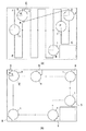
図8は、本体1の掃除走行の一例を示す模式図である。自走式掃除機Pは、まず、部屋の中央部分、つまり、壁際や隅部以外の掃除を行う。例えば、図8(a)のように、本体1は地点Aから出発し、本体距離センサ9を用いて部屋の壁を見つけ、壁まで直進すると壁に沿って自身の車幅分だけシフトして反転して、対向する壁まで逆方向に直進するといった反復運動を行う。そして、地点Dまで到達して出発地点Aより右側の区域の掃除が済むと、出発地点Aまで戻り、左側の区域の掃除を行う。この動作を繰り返すことにより、壁際や隅部以外の掃除を一様に行うことができる。
【0034】
そして、制御部25は、本体距離センサ10の検知情報に基づき、例えば、反転地点を壁際と判断して部屋のマッピングを行い、その地図情報をメモリ26に蓄えている。このとき、反転地点のうち地点B〜Fのように、本体1外周から障害物や壁面までの間にシフト幅分の距離が確保できない地点を隅部と判断し、メモリ26に記憶している。
【0035】
なお、従来公知の自走式掃除機のように、壁から壁に向かってランダムに走行し、結果的に室内全体を掃除する方法を採用することも可能である。
【0036】
自走式掃除機Pは、部屋の中央部分の掃除を終えると、可動ノズル5を180°回動させることで、ノズル吸込口12を本体1の外部に突出させ、壁際(部屋の外周や障害物の近傍)や隅部の掃除を開始する。例えば、図8(b)のように、壁際に沿って周回しながら壁際や隅部の掃除を行う。このとき、自走式掃除機Pは主にノズル距離センサ10の情報を頼りに壁沿いに周回する。これにより、従来では掃除できなかった壁際や部屋の隅のゴミを吸い取ることが可能となる。
【0037】
また、可動ノズル5が、回転軸5より着脱、交換可能としてもよい。これにより、例えば、フローリングには可動ノズル5に替えて柔らかいモップのような清掃具を使用し、絨毯には固い毛のブラシ付きを用いてノズルを使用するといったような、床面に合わせた使い分けが可能となる。また、可動ノズル5よりも先細なノズルを使用することで、タンスと壁の隙間など、本体1が到達し得ない狭い部分の清掃を行うことが可能となる。
【0038】
【発明の効果】
本発明によると、先端部が直角やそれ以下の鋭角になった可動ノズルを突出させることで、従来では掃除できなかった壁際や部屋の隅部の掃除が行なえる。
【図面の簡単な説明】
【図1】 本発明に係る自走式掃除機を横から見た外観斜視図である。
【図2】 同上自走式掃除機の本体を底面から見た外観斜視図である。
【図3】 上記自走式掃除機の可動ノズルを上面(a)及び底面(b)から見た斜視図である。
【図4】 上記自走式掃除機の可動ノズルの回転駆動機構を本体の内部から見た斜視図である。
【図5】 同上回転駆動機構の分解斜視図である。
【図6】 上記自走式掃除機の可動ノズルの先端部を本体外側へ突出させた状態を上面から見た斜視図である。
【図7】 上記自走式掃除機の制御系統のブロック図である。
【図8】 上記自走式掃除機の掃除走行の一例を示す模式図である。
【図9】 上記自走式掃除機の可動ノズル近傍の拡大平面図である。
【符号の説明】
P 自走式掃除機
1 本体
2 本体吸込口
3 走行輪
5 可動ノズル
6 回転軸
8 スライド孔
9 本体距離センサ
10 ノズル距離センサ
12 ノズル吸込口
51 可動ノズルの先端部[0001]
BACKGROUND OF THE INVENTION
The present invention relates to a self-propelled cleaner.
[0002]
[Prior art]
Recently, self-propelled vacuum cleaners for home use have appeared and have been released. Self-propelled vacuum cleaners usually have a flat cylindrical shape, and are equipped with moving means such as wheels and distance detection means to walls and obstacles while moving around the room without any difficulty. Can be cleaned automatically.
[0003]
However, since these preceding self-propelled cleaners mainly perform cleaning by sucking dust at the suction port at the lower part of the main body, it is not possible to clean the corners of the room that cannot be reached by the wall or the main body. There is a problem.
[0004]
Therefore, in
[0005]
[Patent Document 1]
Japanese Patent Laid-Open No. 7-16190
[Problems to be solved by the invention]
However, even in the example of
[0007]
The present invention has been made in view of the above problems, and an object of the present invention is to provide a self-propelled cleaner that can efficiently clean an area that the main body cannot reach, such as a corner of a room.
[0008]
[Means for Solving the Problems]
In order to achieve the above object, a self-propelled cleaner of the present invention includes a moving means for moving a main body having a circular outer periphery on a floor surface of a cleaning area, and an electric blower that is provided in the main body and generates a dust suction airflow. And a main body suction port that opens on the bottom surface of the main body, and a movable nozzle that has a sharp-shaped or right-angled tip and is housed inside the outer periphery of the main body and is rotatable in a direction parallel to the floor surface. And a rotating mechanism of the movable nozzle, and a nozzle suction port formed as desired on the floor surface at the tip of the movable nozzle, when cleaning the central portion in the cleaning area, the movable nozzle, The tip is directed toward the center of the main body and the circular arc portion is accommodated along the outer periphery of the main body, and the movable nozzle is rotated 180 ° when cleaning the wall or corner in the cleaning area. The tip of the Characterized in that, characterized in that to protrude outward from the outer periphery of the body.
[0010]
An impact mitigation mechanism is provided that urges the rotating shaft of the movable nozzle to the outside of the main body so as to be slidable. Thus, even when the movable nozzle collides with a wall or the like, the movable nozzle retracts to the inside of the main body, so that the impact applied to the main body can be reduced.
[0011]
Furthermore, the rotating shaft of the movable nozzle also serves as a suction pipe, or a suction hose is coaxially inserted into the rotating shaft of the movable nozzle. Thereby, the said impact relaxation mechanism can be constructed | assembled compactly.
[0012]
And it travels on the wall side based on the detection information of the nozzle distance sensor provided in the said movable nozzle, It is characterized by the above-mentioned. Thereby, it becomes possible to reduce an error rather than traveling along the wall with only the main body distance sensor.
[0014]
The movable nozzle is detachably provided. Thereby, it becomes possible to use the cleaning tool which differs in a form according to the condition of the floor surface, and fine and fine cleaning can be realized.
[0015]
DETAILED DESCRIPTION OF THE INVENTION
Embodiments of the present invention will be described below with reference to the drawings. FIG. 1 is an external perspective view of a self-propelled cleaner according to the present invention as seen from the side. The
[0016]
A main
[0017]
In addition, the
[0018]
In addition, a
[0019]
Next, the attachment state of the
[0020]
FIG. 3 is a perspective view of the
[0021]
The angle of the
[0022]
A plurality of
[0023]
Further, a short
[0024]
FIG. 4 is a perspective view of the rotating mechanism of the
[0025]
Further, a
[0026]
Then, the
[0027]
Then, the
[0028]
The
[0029]
FIG. 9 is an enlarged plan view thereof. As described above, the
[0030]
FIG. 7 is a block diagram of a control system of the self-propelled cleaner. The main
[0031]
That is, when the
[0032]
The distance information detected by the main
[0033]
FIG. 8 is a schematic diagram illustrating an example of cleaning travel of the
[0034]
Then, based on the detection information of the main
[0035]
In addition, it is also possible to employ | adopt the method of running at random from a wall toward a wall like a conventionally well-known self-propelled cleaner, and cleaning the whole room as a result.
[0036]
When the self-propelled cleaner P finishes cleaning the central portion of the room, the
[0037]
The
[0038]
【The invention's effect】
According to the present invention, by projecting the movable nozzle whose tip portion has a right angle or less acute angle, it is possible to clean a wall or a corner of a room that could not be cleaned conventionally.
[Brief description of the drawings]
FIG. 1 is an external perspective view of a self-propelled cleaner according to the present invention as viewed from the side.
FIG. 2 is an external perspective view of the main body of the self-propelled cleaner as seen from the bottom.
FIG. 3 is a perspective view of the movable nozzle of the self-propelled cleaner as viewed from the top surface (a) and the bottom surface (b).
FIG. 4 is a perspective view of the movable nozzle rotation drive mechanism of the self-propelled cleaner as viewed from the inside of the main body.
FIG. 5 is an exploded perspective view of the rotational drive mechanism.
FIG. 6 is a perspective view of a state in which a tip of a movable nozzle of the self-propelled cleaner is protruded to the outside of the main body as viewed from above.
FIG. 7 is a block diagram of a control system of the self-propelled cleaner.
FIG. 8 is a schematic view showing an example of cleaning traveling of the self-propelled cleaner.
FIG. 9 is an enlarged plan view near the movable nozzle of the self-propelled cleaner.
[Explanation of symbols]
P Self-propelled
Claims (5)
Priority Applications (1)
| Application Number | Priority Date | Filing Date | Title |
|---|---|---|---|
| JP2003069048A JP4190318B2 (en) | 2003-03-14 | 2003-03-14 | Self-propelled vacuum cleaner |
Applications Claiming Priority (1)
| Application Number | Priority Date | Filing Date | Title |
|---|---|---|---|
| JP2003069048A JP4190318B2 (en) | 2003-03-14 | 2003-03-14 | Self-propelled vacuum cleaner |
Publications (2)
| Publication Number | Publication Date |
|---|---|
| JP2004275304A JP2004275304A (en) | 2004-10-07 |
| JP4190318B2 true JP4190318B2 (en) | 2008-12-03 |
Family
ID=33286184
Family Applications (1)
| Application Number | Title | Priority Date | Filing Date |
|---|---|---|---|
| JP2003069048A Expired - Fee Related JP4190318B2 (en) | 2003-03-14 | 2003-03-14 | Self-propelled vacuum cleaner |
Country Status (1)
| Country | Link |
|---|---|
| JP (1) | JP4190318B2 (en) |
Cited By (1)
| Publication number | Priority date | Publication date | Assignee | Title |
|---|---|---|---|---|
| JP2014184074A (en) * | 2013-03-25 | 2014-10-02 | Mitsubishi Electric Corp | Self-propelled vacuum cleaner |
Families Citing this family (5)
| Publication number | Priority date | Publication date | Assignee | Title |
|---|---|---|---|---|
| KR101211498B1 (en) * | 2006-12-18 | 2012-12-12 | 삼성전자주식회사 | Cleaning Robot |
| JP2015043788A (en) * | 2013-08-27 | 2015-03-12 | シャープ株式会社 | Self-propelled floor surface treatment device |
| JPWO2018123321A1 (en) * | 2016-12-26 | 2019-10-31 | パナソニックIpマネジメント株式会社 | Autonomous traveling vacuum cleaner |
| EP3695766A4 (en) * | 2017-10-13 | 2021-05-05 | Chiba Institute of Technology | Self-propelled vacuum cleaner |
| JP6655804B2 (en) | 2017-11-10 | 2020-02-26 | パナソニックIpマネジメント株式会社 | Mobile robot and mobile robot control method |
Family Cites Families (6)
| Publication number | Priority date | Publication date | Assignee | Title |
|---|---|---|---|---|
| JP2594810Y2 (en) * | 1991-08-22 | 1999-05-10 | 日本電気ホームエレクトロニクス株式会社 | Self-propelled vacuum cleaner |
| JPH0642594Y2 (en) * | 1993-03-08 | 1994-11-09 | 株式会社建都デザインセンター | Vacuum cleaner suction unit |
| JPH0716190A (en) * | 1993-07-02 | 1995-01-20 | Matsushita Electric Ind Co Ltd | Automatic vacuum cleaner |
| JPH07313417A (en) * | 1994-05-30 | 1995-12-05 | Minolta Co Ltd | Self-running working car |
| JPH09154780A (en) * | 1995-12-05 | 1997-06-17 | Ryuzo Washisaki | Article for cleaning clearance by attaching attachment and suction tool to electric vacuum cleaner |
| JP2003047579A (en) * | 2001-08-06 | 2003-02-18 | Toshiba Tec Corp | Vacuum cleaner |
-
2003
- 2003-03-14 JP JP2003069048A patent/JP4190318B2/en not_active Expired - Fee Related
Cited By (1)
| Publication number | Priority date | Publication date | Assignee | Title |
|---|---|---|---|---|
| JP2014184074A (en) * | 2013-03-25 | 2014-10-02 | Mitsubishi Electric Corp | Self-propelled vacuum cleaner |
Also Published As
| Publication number | Publication date |
|---|---|
| JP2004275304A (en) | 2004-10-07 |
Similar Documents
| Publication | Publication Date | Title |
|---|---|---|
| JP5809227B2 (en) | Robot system | |
| JPH0732751B2 (en) | Self-propelled vacuum cleaner | |
| US8032978B2 (en) | Robotic cleaning device | |
| KR101249864B1 (en) | Robot cleaner | |
| KR101892652B1 (en) | Electric cleaner | |
| US20050166356A1 (en) | Self-propelled vacuum cleaner | |
| JP4097264B2 (en) | Electric vacuum cleaner | |
| JP2001258807A (en) | Self-traveling vacuum cleaner | |
| JP2007330567A (en) | Self-traveling type vacuum cleaner | |
| JP2006087507A (en) | Self-propelled cleaner | |
| JPH0732752B2 (en) | Self-propelled vacuum cleaner | |
| WO2016056226A1 (en) | Autonomous travel-type cleaner | |
| JP2017213009A (en) | Autonomous travel type cleaner | |
| JP6217952B2 (en) | Robot vacuum cleaner | |
| CN110507238B (en) | Autonomous walking type dust collector | |
| JP6757575B2 (en) | Self-propelled vacuum cleaner | |
| KR20150141979A (en) | Robotic vacuum cleaner with protruding sidebrush | |
| JP4190318B2 (en) | Self-propelled vacuum cleaner | |
| JP3115174B2 (en) | Self-propelled vacuum cleaner | |
| JP3724637B2 (en) | Cleaning device | |
| JP6888847B2 (en) | Self-propelled vacuum cleaner | |
| KR101052182B1 (en) | Corner cleaning device and cleaner having same | |
| TW201918212A (en) | Autonomous travel type electric robot vacuum cleaner capable of setting a cleaning zone in response to user's preference | |
| JP2004337301A (en) | Cleaning robot | |
| TW201918211A (en) | Autonomous travel type electric robot vacuum cleaner capable of easily crossing a height difference |
Legal Events
| Date | Code | Title | Description |
|---|---|---|---|
| A621 | Written request for application examination |
Free format text: JAPANESE INTERMEDIATE CODE: A621 Effective date: 20050810 |
|
| RD01 | Notification of change of attorney |
Free format text: JAPANESE INTERMEDIATE CODE: A7421 Effective date: 20070827 |
|
| A977 | Report on retrieval |
Free format text: JAPANESE INTERMEDIATE CODE: A971007 Effective date: 20071207 |
|
| A131 | Notification of reasons for refusal |
Free format text: JAPANESE INTERMEDIATE CODE: A131 Effective date: 20080527 |
|
| A521 | Written amendment |
Free format text: JAPANESE INTERMEDIATE CODE: A523 Effective date: 20080630 |
|
| TRDD | Decision of grant or rejection written | ||
| A01 | Written decision to grant a patent or to grant a registration (utility model) |
Free format text: JAPANESE INTERMEDIATE CODE: A01 Effective date: 20080916 |
|
| A01 | Written decision to grant a patent or to grant a registration (utility model) |
Free format text: JAPANESE INTERMEDIATE CODE: A01 |
|
| A61 | First payment of annual fees (during grant procedure) |
Free format text: JAPANESE INTERMEDIATE CODE: A61 Effective date: 20080916 |
|
| FPAY | Renewal fee payment (event date is renewal date of database) |
Free format text: PAYMENT UNTIL: 20110926 Year of fee payment: 3 |
|
| R150 | Certificate of patent or registration of utility model |
Free format text: JAPANESE INTERMEDIATE CODE: R150 |
|
| LAPS | Cancellation because of no payment of annual fees |