JP4189257B2 - Zoom lens system - Google Patents
Zoom lens system Download PDFInfo
- Publication number
- JP4189257B2 JP4189257B2 JP2003111307A JP2003111307A JP4189257B2 JP 4189257 B2 JP4189257 B2 JP 4189257B2 JP 2003111307 A JP2003111307 A JP 2003111307A JP 2003111307 A JP2003111307 A JP 2003111307A JP 4189257 B2 JP4189257 B2 JP 4189257B2
- Authority
- JP
- Japan
- Prior art keywords
- lens
- lens group
- focal length
- positive
- group
- Prior art date
- Legal status (The legal status is an assumption and is not a legal conclusion. Google has not performed a legal analysis and makes no representation as to the accuracy of the status listed.)
- Expired - Fee Related
Links
Images


Landscapes
- Lenses (AREA)
Description
【0001】
【技術分野】
本発明は、主に電子スチルカメラ(デジタルカメラ)に用いられる、ズーム比(変倍比)2〜3倍程度で広角域(半画角30°以上)を含むズームレンズ系に関する。
【0002】
【従来技術及びその問題点】
近年、デジタルカメラの小型化と高精細化のニーズが高まり、CCD撮像素子の画素が微細化されている。そのためデジタルカメラの撮影レンズは、高解像度であることが要求される。さらにフィルター類を配置するために長いバックフォーカスも必要とされる。また、カラーCCD用の光学系は、シェーディングや色ずれ防止のために、レンズ最終面からの射出光が撮像面にできるだけ垂直に入射する、いわゆるテレセントリック性の良いことが求められる。
【0003】
コンパクトタイプのデジカメ用小型ズームレンズ系として、ズーム比2〜3倍程度のものは、負レンズ先行型(ネガティブリード型)のレンズ系(テレフォトタイプ)が良く用いられる。これらのレンズ系では短焦点距離端の広角化とレンズ系の小型化、特に前玉(最も物体側のレンズ)の小径化ができるため、収納時にレンズ群の間隔を圧縮して収納するいわゆる沈胴ズーム用に適している。また、射出瞳位置を像面より十分遠方にする必要から、物体側から順に負正正の3成分からなるいわゆる3群ズームレンズ系がよく用いられる。このような3群ズームレンズ系は、例えば、特開平10‐213745号公報、同10‐170826号公報等で提案されている。
【0004】
しかし、特開平10‐213745号公報では、レンズ枚数を削減し小型化を図っているが、焦点距離に対して前玉径やレンズ全長が大きく、小型化が十分達成されているとは言えない。また、同10‐170826号公報では、小型化を達成したテレセントリック光学系が提案されているが、構成枚数が7枚と多いため、レンズ系の沈胴収納長が長くなり、カメラが大型化してしまう問題がある。小型沈胴式カメラ用のズームレンズ系は、カメラ本体の小型化のために前玉径とレンズ全長が小さいことに加えて、各レンズ群の厚さも小さいことが求められている。一般的にレンズ系の小型化や群厚を小さくするために構成枚数を削減すると、収差補正の難易度が増す。小型化を図りながら全変倍範囲に渡り諸収差を良好に補正するためには、適切な各レンズ群の屈折力配置やレンズ構成が必要となる。
【0005】
【発明の目的】
本発明は、テレフォトタイプの3群ズームレンズ系であって、ズーム比が2〜3倍程度の広角域(半画角30°以上)を含む小型のデジタルカメラ用ズームレンズ系を得ることを目的とする。
【0006】
【発明の概要】
本発明のズームレンズ系は、物体側から順に、負の屈折力を有する第1レンズ群と、正の屈折力を有する第2レンズ群と、正の屈折力を有する第3レンズ群とからなり、短焦点距離端から長焦点距離端へのズーミングに際し、前記第1レンズ群と第2レンズ群の間隔は減少し、第2レンズ群と第3レンズ群の間隔は増大するように移動し、第1レンズ群は、物体側から順に、負レンズ1枚と正レンズ1枚で構成され、第2レンズ群は、物体側から順に、正レンズ1枚と負レンズ1枚で構成され、第3レンズ群は正レンズ1枚で構成され、次の条件式(1)、(2)、(3)及び(5)を満足することを特徴としている。
(1)0.4<(fw・ft)1/2/|f1|<0.8 (f1<0)
(2)0.7<(fw・ft)1/2/f2<1.4
(3)0.4<(fw・ft)1/2/f3<0.9
(5)νs≦21.3
但し、
fw:短焦点距離端での全系焦点距離、
ft:長焦点距離端での全系焦点距離、
fi:第iレンズ群の焦点距離(i=1〜3)、
νs:第2レンズ群の像側のレンズのアッベ数、
である。
【0007】
第2レンズ群の最も像側のレンズは、像側に凹面を向けたレンズから構成するのが好ましく、さらに次の条件式(4)を満足させるのが好ましい。
(4)0.4<|Rs|/fw<0.8
但し、
Rs:上記像側に凹面を有するレンズの像側の面の曲率半径、
である。
【0008】
【発明の実施の形態】
本発明のズームレンズ系は、図13の簡易移動図に示すように、物体側から順に、負の第1レンズ群10と、絞りSと、正の第2レンズ群20と、正の第3レンズ群30とからなっている。この3群ズームレンズは、短焦点距離端(W)から長焦点距離端(T)へのズーミングに際し、前記第1レンズ群10と第2レンズ群20の間隔は減少し、第2レンズ群20と第3レンズ群30の間隔は増大するように移動する。絞りSは、第2レンズ群20と一緒に移動する。フォーカシングは第1レンズ群10で行う。CGは、撮像素子の前方に位置する赤外カットフィルタ等のカバーガラス(平行平面板)である。
【0009】
条件式(1)は、中間焦点距離((fw・ft)1/2)に対する第1レンズ群の焦点距離の範囲を規定している。
条件式(1)の下限を超えると、第1レンズ群10の負の屈折力が小さくなり、短焦点距離端でのバックフォーカスが不足する。また、広角化も困難となる。
条件式(1)の上限を超えて第1レンズ群10の負の屈折力が大きくなると、各群の屈折力が強くなり、収差補正が困難となり、良好な結像性能が得られなくなる。また、バックフォーカスが長くなるため、レンズ全長の増大を招く。
【0010】
条件式(2)は、中間焦点距離に対する第2レンズ群20の焦点距離の範囲を規定している。正の第2レンズ群20は、本ズームレンズ系の主な変倍作用を担っており、適切な屈折力を設定する必要がある。
条件式(2)の下限を超えて第2レンズ群20の正の屈折力が小さくなると、3倍程度の変倍比を得るときの移動量が増えるため、長焦点距離端でのレンズ全長が長くなってしまう。
条件式(2)の上限を超えて第2レンズ群20の正の屈折力が大きくなると、各群の屈折力が強くなり、収差補正が困難となり、良好な結像性能が得られなくなる。
【0011】
条件式(3)は、中間焦点距離に対する第3レンズ群30の焦点距離の範囲を規定している。正の第3レンズ群30は、主に射出瞳位置を像面より遠くにしテレセントリック性を確保する役割を担っている。
条件式(3)の下限を超えると、第3レンズ群30の正の屈折力が小さくなるため、短焦点距離端において射出瞳位置が像面に近づき、テレセントリック性が保てなくなる。
条件式(3)の上限を超えて第3レンズ群30の正の屈折力が大きくなると、相対的に第2レンズ群20の正の屈折力が小さくなるため、長焦点距離端でのレンズ全長が増大してしまう。また、長焦点距離端での像面湾曲収差と非点収差が悪化し、良好な結像性能が得られなくなる。
【0012】
第2レンズ群20の最も像側のレンズは、像側に凹面の強い発散作用を有するレンズから構成することが望ましく、この凹レンズは、条件式(4)を満足することが好ましい。
条件式(4)は、短焦点距離端の全系焦点距離に対する第2レンズ群20の最も像側の凹面の曲率半径の範囲を規定したもので、短焦点距離端における、レンズ系の小型化とテレセントリック性の確保の両立を図るためのものである。
条件式(4)の下限を超えてこの面の曲率半径が小さくなると、レンズ全長は短くできるが、射出瞳位置が像面に近くなりすぎてしまい、テレセントリック性が失われる。
条件式(4)の上限を超えてこの面の曲率半径が大きくなると、テレセントリック性を保つために第2レンズ群20と第3レンズ群30の間隔が増大し、レンズ全長が増大してしまう。
【0013】
沈胴収納時の長さを短くするためには、各レンズ群の構成枚数を減らす必要がある。具体的には、第1レンズ群10を物体側から順に負正の2枚で構成し、主なる変倍作用を担う第2レンズ群20は物体側から順に正負の2枚で構成し、テレセントリック性を確保する役割の第3レンズ群30は正レンズ1枚で構成している。
【0014】
さらに、第1レンズ群中の正の屈折力の第2レンズは少なくとも1面を非球面とすると、短焦点距離端での歪曲収差やコマ収差・非点収差等の軸外収差を良好に補正することが可能となる。また上記非球面レンズは、ガラスまたはプラスチックで作製されるが、プラスチックレンズとするとコスト低減が可能となる。
【0015】
また、第2レンズ群20を正負の2枚構成とした結果、1枚の正レンズの屈折力が強くなり、変倍に伴う球面収差等の収差変動を抑えるのが難しくなるため、正レンズは少なく とも1面を非球面とすることが好ましく、両面を非球面とすると、変倍による変動する球面収差、コマ収差を小さくすることができる。さらに、条件式(5)は、第2レンズ群20の像側の負レンズが満足すべきアッベ数に関する条件である。条件式(5)の下限を超えると、変倍に伴う軸上・倍率色収差の変動が大きくなり、良好な結像性能が保てなくなる。
【0016】
第2レンズ群20の最も物体側の正レンズは、非球面を設けるとさらに良好な結像性能となる。物体側面または像側面の少なくともいずれか一方を周辺に向かうに従って正の屈折力が弱くなる非球面にすることにより、全焦点距離範囲において球面収差の変動を小さくでき、また長焦点距離側でのコマ収差をさらに良好に補正することが可能となる。この非球面レンズはガラスまたはプラスチックのどちらでも作製可能であるが、屈折力が強いためにガラスレンズとすることが好ましい。
【0017】
次に具体的な実施例を示す。諸収差図及び表中、球面収差で表される色収差(軸上色収差)図及び倍率色収差図中のd線、g線、C線はそれぞれの波長に対する収差であり、Sはサジタル、Mはメリディオナル、FNOはFナンバー、fは全系の焦点距離、Wは半画角(゜)、fBはバックフォーカス、rは曲率半径、dはレンズ厚またはレンズ間隔、Nd はd線の屈折率、νdはアッベ数を示す。
実施例で最後の平行平面板(面番号12及び13)はカバーガラスやローパスフィルター等のフィルタ類を表しており、光学性能上は像側レンズと像面の間の任意の位置に配置できる。
また、回転対称非球面は次式で定義される。
x=cy2/[1+[1-(1+K)c2y2]1/2]+A4y4+A6y6+A8y8+A10y10+A12y12・・・
(但し、xは非球面形状、cは曲率、yは光軸からの高さ、Kは円錐係数、A4、A6、A8、A10・・・・・は各次数の非球面係数)
【0018】
[実施例1]
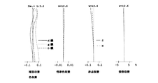
図1は、本発明のズームレンズ系の実施例1のレンズ構成図であり、第1レンズ群10は、物体側から順に、負レンズ11と正レンズ12とからなり、第2レンズ群20は、物体側から順に、正レンズ21と、像側に凹面を向けた負メニスカスレンズ22とからなり、第3レンズ群30は、正の単レンズからなっている。CGは、撮像素子の前に位置するカバーガラス(フィルター類)である。絞りは第5面の前方(物体側)0.7の位置に配置されていて、ズーミングに際し第2レンズ群20と一体で移動する。図2、図3及び図4は、それぞれ、このズームレンズ系の短焦点距離端、中間焦点距離、及び長焦点距離端における諸収差図、表1はその数値データである。
【0019】
(表1)
FNO.=1:2.7‐3.6‐5.2
f= 7.25‐12.10‐20.64(ズーム比=2.85)
W=32.9‐20.4‐12.3
fB=0.00‐0.00‐0.00
面NO. r d Nd νd
1 51.813 0.90 1.77250 49.6
2 7.251 2.72
3* 20.298 2.40 1.80518 25.4
4* 83.771 16.95‐8.15‐2.7
5* 7.327 2.50 1.72916 54.7
6* -18.987 0.10
7 16.947 3.73 1.92286 21.3
8 4.634 4.80‐9.64‐18.1
9 23.922 2.80 1.72916 54.7
10 -24.519 2.73
11 ∞ 1.51 1.51633 64.1
12 ∞ 0.50
13 ∞ 0.50 1.51633 64.1
14 ∞
*は回転対称非球面。
非球面データ(表示していない非球面係数は0.00である。):
面NO. K A4 A6 A8
3 0.00 -0.27398×10⁻⁴ -0.14171×10⁻⁵ 0.88000×10⁻⁷
4 0.00 -0.21862×10⁻³ 0.51925×10⁻⁶ 0.00
5 0.00 -0.32331×10⁻³ -0.54123×10⁻⁵ 0.99049×10⁻⁷
6 0.00 0.28664×10⁻³ -0.47358×10⁻⁵ 0.68722×10⁻⁷
【0020】
[実施例2]
図5は、本発明のズームレンズ系の実施例2のレンズ構成図を示し、図6、図7及び図8は、それぞれ、このズームレンズ系の短焦点距離端、中間焦点距離、及び長焦点距離端における諸収差図、表2はその数値データである。基本的なレンズ構成は、実施例1と同様である。絞りは第5面の前方(物体側)0.7の位置に配置されていて、ズーミングに際し第2レンズ群20と一体で移動
する。
【0021】
(表2)
FNO.=1:2.7‐3.4‐5.3
f=8.00‐12.50‐24.03(ズーム比=3.00)
W=30.4‐19.8‐10.6
fB=0.00‐0.00‐0.00
面NO. r d Nd νd
1 35.725 0.90 1.83481 42.7
2 7.646 2.17
3* 13.231 2.40 1.84666 23.8
4* 25.272 17.99‐9.74‐2.70
5* 7.110 2.50 1.77250 49.6
6 -28.219 0.20
7* 18.266 3.50 1.92286 21.3
8 4.880 4.92‐8.97‐19.37
9 30.098 2.80 1.69680 55.5
10 -21.514 2.95
11 ∞ 1.51 1.51633 64.1
12 ∞ 0.50
13 ∞ 0.50 1.51633 64.1
14 ∞
*は回転対称非球面。
非球面データ(表示していない非球面係数は0.00である。):
面NO. K A4 A6 A8
3 0.00 -0.88427×10⁻⁴ -0.16679×10⁻⁵ 0.43529×10⁻⁷
4 0.00 -0.23870×10⁻³ -0.62834×10⁻⁶ 0.00
5 0.00 -0.11983×10⁻³ -0.25840×10⁻⁵ 0.00
7 0.00 -0.45509×10⁻³ -0.86460×10⁻⁵ 0.16360×10⁻⁶
【0022】
[実施例3]
図9は、本発明のズームレンズ系の実施例3のレンズ構成図を示し、図10、図11及び図12は、それぞれ、このズームレンズ系の短焦点距離端、中間焦
点距離、及び長焦点距離端における諸収差図、表3はその数値データである。基本的なレンズ構成は、実施例1と同様である。絞りは第5面の前方(物体側)0.67の位置に配置されていて、ズーミングに際し第2レンズ群20と一体で移動する。
【0023】
(表3)
FNO.=1:2.7‐3.5‐4.8
f=5.70‐9.00‐14.30(ズーム比=2.51)
W=32.9‐21.7‐14.1
fB=2.70‐2.70‐2.70
面NO. r d Nd νd
1 16.171 0.90 1.77250 49.6
2 4.553 1.70
3* 8.879 1.60 1.84666 23.8
4* 13.209 11.05‐6.14‐3.00
5* 4.433 2.00 1.69350 53.2
6* -18.477 0.20
7 7.137 1.00 1.92286 21.3
8 3.193 3.14‐6.99‐13.17
9 75.707 2.00 1.58913 61.2
10 -10.659 0.80
11 ∞ 1.50 1.51633 64.1
12 ∞ 0.50
13 ∞ 0.50 1.51633 64.1
14 ∞
*は回転対称非球面。
非球面データ(表示していない非球面係数は0.00である。):
面NO. K A4 A6 A8
3 0.00 -0.83561×10⁻³ 0.22557×10⁻⁴ -0.78955×10-
4 0.00 -0.16518×10⁻² 0.38674×10⁻⁴ -0.24551×10⁻⁵
5 0.00 -0.12186×10⁻² -0.15219×10⁻⁴ 0.00
6 0.00 0.82006×10⁻³ 0.20843×10⁻⁴ 0.00
【0024】
各実施例の各条件式に対する値を表4に示す。
(表4)
実施例1 実施例2 実施例3
条件式(1) 0.677 0.683 0.734
条件式(2) 1.017 1.078 0.957
条件式(3) 0.732 0.753 0.564
条件式(4) 0.643 0.610 0.560
条件式(5) 21.3 21.3 21.3
【0025】
【発明の効果】
本発明によれば、テレフォトタイプの3群ズームレンズであって、ズーム比が2〜3倍程度の小型のデジタルカメラ用ズームレンズ系を得ることができる。
【図面の簡単な説明】
【図1】 本発明によるズームレンズ系の実施例1のレンズ構成図である。
【図2】 図1のレンズ構成の短焦点距離端における諸収差図である。
【図3】 図1のレンズ構成の中間焦点距離における諸収差図である。
【図4】 図1のレンズ構成の長焦点距離端における諸収差図である。
【図5】 本発明によるズームレンズ系の実施例2のレンズ構成図である。
【図6】 図5のレンズ構成の短焦点距離端における諸収差図である。
【図7】 図5のレンズ構成の中間焦点距離における諸収差図である。
【図8】 図5のレンズ構成の長焦点距離端における諸収差図である。
【図9】 本発明によるズームレンズ系の実施例3のレンズ構成図である。
【図10】 図9のレンズ構成の短焦点距離端における諸収差図である。
【図11】 図9のレンズ構成の中間焦点距離における諸収差図である。
【図12】 図9のレンズ構成の長焦点距離端における諸収差図である。
【図13】 本発明によるズームレンズ系の簡易移動図である。[0001]
【Technical field】
The present invention relates to a zoom lens system mainly used in an electronic still camera (digital camera) and including a wide angle region (half angle of view of 30 ° or more) with a zoom ratio (magnification ratio) of about 2 to 3 times.
[0002]
[Prior art and its problems]
In recent years, the need for miniaturization and high definition of digital cameras has increased, and the pixels of CCD image sensors have been miniaturized. Therefore, the photographing lens of the digital camera is required to have a high resolution. In addition, a long back focus is required to arrange the filters. Further, an optical system for a color CCD is required to have so-called telecentricity in which light emitted from the last lens surface is incident on the imaging surface as perpendicularly as possible to prevent shading and color misregistration.
[0003]
As a compact zoom lens system for a digital camera, a negative lens leading type (negative lead type) lens system (telephoto type) is often used when the zoom ratio is about 2 to 3 times. These lens systems can widen the short focal length and reduce the size of the lens system, especially the diameter of the front lens (most object side lens). Suitable for zooming. In addition, since the exit pupil position needs to be sufficiently far from the image plane, a so-called three-group zoom lens system including three negative and positive components in order from the object side is often used. Such a three-group zoom lens system is proposed in, for example, Japanese Patent Application Laid-Open Nos. 10-213745 and 10-170826.
[0004]
However, in Japanese Patent Laid-Open No. 10-213745, the number of lenses is reduced and the size is reduced. However, the front lens diameter and the entire lens length are large with respect to the focal length, and it cannot be said that the size reduction is sufficiently achieved. . Also, in Japanese Patent Laid-Open No. 10-170826, a telecentric optical system that achieves miniaturization is proposed, but since the number of components is as large as seven, the retractable storage length of the lens system becomes long and the camera becomes large. There's a problem. In order to reduce the size of the camera body, a zoom lens system for a compact retractable camera is required to have a small front lens diameter and a small total lens length, as well as a small thickness for each lens group. In general, if the number of components is reduced in order to reduce the size of the lens system and the group thickness, the degree of difficulty in correcting aberrations increases. In order to satisfactorily correct various aberrations over the entire zooming range while reducing the size, an appropriate refractive power arrangement and lens configuration of each lens group is required.
[0005]
OBJECT OF THE INVENTION
The present invention provides a telephoto type three-group zoom lens system, which is a small zoom lens system for a digital camera including a wide angle region (half angle of view of 30 ° or more) with a zoom ratio of about 2 to 3 times. Objective.
[0006]
SUMMARY OF THE INVENTION
The zoom lens system of the present invention includes, in order from the object side, a first lens group having a negative refractive power, a second lens group having a positive refractive power, and a third lens group having a positive refractive power. When zooming from the short focal length end to the long focal length end, the distance between the first lens group and the second lens group is decreased, and the distance between the second lens group and the third lens group is increased. The first lens group is composed of one negative lens and one positive lens in order from the object side, and the second lens group is composed of one positive lens and one negative lens in order from the object side. The lens group is composed of one positive lens, and satisfies the following conditional expressions (1), (2), (3), and (5) .
(1) 0.4 <(fw · ft) 1/2 /|f1|<0.8 (f1 <0)
(2) 0.7 <(fw · ft) 1/2 /f2<1.4
(3) 0.4 <(fw · ft) 1/2 /f3<0.9
(5) νs ≦ 21.3
However,
fw: total focal length at the short focal length end,
ft: total system focal length at the long focal length end,
fi: focal length of the i-th lens group (i = 1 to 3),
νs: Abbe number of the lens on the image side of the second lens group,
It is.
[0007]
The most image-side lens in the second lens group is preferably composed of a lens having a concave surface directed to the image side, and further preferably satisfies the following conditional expression (4).
(4) 0.4 <| Rs | / fw <0.8
However,
Rs: radius of curvature of the image side surface of the lens having a concave surface on the image side,
It is.
[0008]
DETAILED DESCRIPTION OF THE INVENTION
In the zoom lens system of the present invention, as shown in the simplified movement diagram of FIG. 13, in order from the object side, the negative
[0009]
Conditional expression (1) defines the range of the focal length of the first lens group with respect to the intermediate focal length ((fw · ft) 1/2 ).
When the lower limit of conditional expression (1) is exceeded, the negative refractive power of the
If the negative refractive power of the
[0010]
Conditional expression (2) defines the range of the focal length of the
If the positive refractive power of the
When the positive refractive power of the
[0011]
Conditional expression (3) defines the range of the focal length of the
If the lower limit of conditional expression (3) is exceeded, the positive refracting power of the
If the positive refractive power of the
[0012]
The most image side lens of the
Conditional expression (4) defines the range of the radius of curvature of the concave surface closest to the image side of the
If the curvature radius of this surface is reduced beyond the lower limit of conditional expression (4), the total lens length can be shortened, but the exit pupil position becomes too close to the image plane, and telecentricity is lost.
When the curvature radius of this surface increases beyond the upper limit of conditional expression (4), the distance between the
[0013]
In order to shorten the length when retracted, it is necessary to reduce the number of lenses in each lens group. Specifically, the
[0014]
Furthermore, if at least one surface of the second lens having a positive refractive power in the first lens group is aspheric, it is possible to satisfactorily correct off-axis aberrations such as distortion, coma and astigmatism at the short focal length end. It becomes possible to do. The aspherical lens is made of glass or plastic, but the cost can be reduced by using a plastic lens.
[0015]
Further, as a result of the
[0016]
If the positive lens closest to the object side in the
[0017]
Next, specific examples will be described. In the various aberration diagrams and tables, the d-line, g-line, and C-line in the chromatic aberration (axial chromatic aberration) diagram and magnification chromatic aberration diagram represented by spherical aberration are the aberrations for each wavelength, S is sagittal, and M is meridional. , FNO is the F number, f is the focal length of the entire system, W is the half angle of view (°), fB is the back focus, r is the radius of curvature, d is the lens thickness or lens spacing, Nd is the refractive index of the d-line, νd Indicates the Abbe number.
In the embodiment, the last plane-parallel plate (
A rotationally symmetric aspherical surface is defined by the following equation.
x = cy2 / [1+ [1- (1 + K) c2y2] 1/2] + A4y4 + A6y6 + A8y8 + A10y10 + A12y12 ...
(Where x is an aspherical shape, c is a curvature, y is a height from the optical axis, K is a conical coefficient, A4, A6, A8, A10... Are aspherical coefficients of each order)
[0018]
[Example 1]
FIG. 1 is a lens configuration diagram of
[0019]
(Table 1)
FNO. = 1: 2.7-3.6-5.2
f = 7.25-12.10-20.64 (zoom ratio = 2.85)
W = 32.9-20.4-12.3
fB = 0.00-0.00-0.00
Surface NO. R d Nd νd
1 51.813 0.90 1.77250 49.6
2 7.251 2.72
3 * 20.298 2.40 1.80518 25.4
4 * 83.771 16.95‐8.15‐2.7
5 * 7.327 2.50 1.72916 54.7
6 * -18.987 0.10
7 16.947 3.73 1.92286 21.3
8 4.634 4.80-9.64-18.1
9 23.922 2.80 1.72916 54.7
10 -24.519 2.73
11 ∞ 1.51 1.51633 64.1
12 ∞ 0.50
13 ∞ 0.50 1.51633 64.1
14 ∞
* Is a rotationally symmetric aspherical surface.
Aspheric data (Aspheric coefficient not shown is 0.00):
Surface No. K A4 A6 A8
3 0.00 -0.27398 × 10 -4 -0.14171 × 10 -5 0.88000 × 10 -7
4 0.00 -0.21862 × 10 -3 0.51925 × 10 -6 0.00
5 0.00 -0.32331 × 10 -3 -0.54123 × 10 -5 0.99049 × 10 -7
6 0.00 0.28664 × 10 -3 -0.47358 × 10 -5 0.68722 × 10 -7
[0020]
[Example 2]
FIG. 5 shows a lens configuration diagram of Embodiment 2 of the zoom lens system of the present invention. FIGS. 6, 7 and 8 respectively show a short focal length end, an intermediate focal length, and a long focal length of the zoom lens system. Various aberration diagrams at the distance end, Table 2 shows numerical data. The basic lens configuration is the same as that of the first embodiment. The stop is disposed at a position 0.7 (front side of the object) 0.7 on the fifth surface, and moves together with the
[0021]
(Table 2)
FNO. = 1: 2.7-3.4-5.3
f = 8.00-12.50-24.03 (zoom ratio = 3.00)
W = 30.4-19.8-10.6
fB = 0.00-0.00-0.00
Surface NO. R d Nd νd
1 35.725 0.90 1.83481 42.7
2 7.646 2.17
3 * 13.231 2.40 1.84666 23.8
4 * 25.272 17.99‐9.74‐2.70
5 * 7.110 2.50 1.77250 49.6
6 -28.219 0.20
7 * 18.266 3.50 1.92286 21.3
8 4.880 4.92‐8.97‐19.37
9 30.098 2.80 1.69680 55.5
10 -21.514 2.95
11 ∞ 1.51 1.51633 64.1
12 ∞ 0.50
13 ∞ 0.50 1.51633 64.1
14 ∞
* Is a rotationally symmetric aspherical surface.
Aspheric data (Aspheric coefficient not shown is 0.00):
Surface No. K A4 A6 A8
3 0.00 -0.88427 × 10 -4 -0.16679 × 10 -5 0.43529 × 10 -7
4 0.00 -0.23870 × 10 -3 -0.62834 × 10 -6 0.00
5 0.00 -0.11983 × 10 -3 -0.25840 × 10 -5 0.00
7 0.00 -0.45509 × 10 -3 -0.86460 × 10 -5 0.16360 × 10 -6
[0022]
[Example 3]
FIG. 9 shows a lens configuration diagram of Embodiment 3 of the zoom lens system of the present invention. FIGS. 10, 11 and 12 respectively show a short focal length end, an intermediate focal length, and a long focal length of the zoom lens system. Various aberration diagrams at the distance end and Table 3 are numerical data. The basic lens configuration is the same as that of the first embodiment. The stop is disposed at a position 0.67 in front of the fifth surface (object side), and moves together with the
[0023]
(Table 3)
FNO. = 1: 2.7-3.5-4.8
f = 5.70-9.00-14.30 (zoom ratio = 2.51)
W = 32.9-21.7-14.1
fB = 2.70-2.70-2.70
Surface NO. R d Nd νd
1 16.171 0.90 1.77250 49.6
2 4.553 1.70
3 * 8.879 1.60 1.84666 23.8
4 * 13.209 11.05-6.14-3.00
5 * 4.433 2.00 1.69350 53.2
6 * -18.477 0.20
7 7.137 1.00 1.92286 21.3
8 3.193 3.14-6.99-13.17
9 75.707 2.00 1.58913 61.2
10 -10.659 0.80
11 ∞ 1.50 1.51633 64.1
12 ∞ 0.50
13 ∞ 0.50 1.51633 64.1
14 ∞
* Is a rotationally symmetric aspherical surface.
Aspheric data (Aspheric coefficient not shown is 0.00):
Surface No. K A4 A6 A8
3 0.00 -0.83561 × 10 -3 0.22557 × 10 -4 -0.78955 × 10 -
4 0.00 -0.16518 × 10 -2 0.38674 × 10 -4 -0.24551 × 10 -5
5 0.00 -0.12186 × 10 -2 -0.15219 × 10 -4 0.00
6 0.00 0.82006 × 10 -3 0.20843 × 10 -4 0.00
[0024]
Table 4 shows values for each conditional expression in each example.
(Table 4)
Example 1 Example 2 Example 3
Conditional expression (1) 0.677 0.683 0.734
Conditional expression (2) 1.017 1.078 0.957
Conditional expression (3) 0.732 0.753 0.564
Conditional expression (4) 0.643 0.610 0.560
Condition (5) 21.3 21.3 21.3
[0025]
【The invention's effect】
According to the present invention, it is possible to obtain a small zoom lens system for a digital camera which is a telephoto type three-group zoom lens and has a zoom ratio of about 2 to 3 times.
[Brief description of the drawings]
FIG. 1 is a lens configuration diagram of
2 is a diagram illustrating various aberrations at a short focal length end of the lens configuration in FIG. 1; FIG.
3 is a diagram illustrating various aberrations at an intermediate focal length of the lens configuration in FIG. 1; FIG.
4 is a diagram illustrating various aberrations at the long focal length end of the lens configuration in FIG. 1; FIG.
FIG. 5 is a lens configuration diagram of Example 2 of a zoom lens system according to the present invention.
6 is a diagram illustrating various aberrations at the short focal length end of the lens configuration in FIG. 5. FIG.
7 is a diagram illustrating various aberrations at an intermediate focal length of the lens configuration in FIG. 5. FIG.
8 is a diagram illustrating various aberrations at the long focal length end of the lens configuration in FIG. 5. FIG.
FIG. 9 is a lens configuration diagram of Example 3 of the zoom lens system according to the present invention.
10 is a diagram illustrating various aberrations at the short focal length end of the lens configuration in FIG. 9. FIG.
FIG. 11 is a diagram illustrating various aberrations at the intermediate focal length of the lens configuration in FIG. 9;
12 is a diagram showing various aberrations at the long focal length end of the lens configuration in FIG. 9. FIG.
FIG. 13 is a simplified movement diagram of a zoom lens system according to the present invention.
Claims (2)
第1レンズ群は、物体側から順に、負レンズ1枚と正レンズ1枚で構成され、第2レンズ群は、物体側から順に、正レンズ1枚と負レンズ1枚で構成され、第3レンズ群は正レンズ1枚で構成され、
次の条件式(1)、(2)、(3)及び(5)を満足することを特徴とするズームレンズ系。
(1)0.4<(fw・ft)1/2/|f1|<0.8 (f1<0)
(2)0.7<(fw・ft)1/2/f2<1.4
(3)0.4<(fw・ft)1/2/f3<0.9
(5)νs≦21.3
但し、
fw:短焦点距離端での全系焦点距離、
ft:長焦点距離端での全系焦点距離、
fi:第iレンズ群の焦点距離(i=1〜3)、
νs:第2レンズ群の像側のレンズのアッベ数。 In order from the object side, a first lens group having negative refractive power, a second lens group having positive refractive power, and a third lens group having positive refractive power, and from the short focal length end to the long focal length During zooming to the distance end, the distance between the first lens group and the second lens group is decreased, and the distance between the second lens group and the third lens group is increased,
The first lens group is composed of one negative lens and one positive lens in order from the object side, and the second lens group is composed of one positive lens and one negative lens in order from the object side. The lens group consists of one positive lens,
A zoom lens system characterized by satisfying the following conditional expressions (1), (2), (3) and (5):
(1) 0.4 <(fw · ft) 1/2 /|f1|<0.8 (f1 <0)
(2) 0.7 <(fw · ft) 1/2 /f2<1.4
(3) 0.4 <(fw · ft) 1/2 /f3<0.9
(5) νs ≦ 21.3
However,
fw: total focal length at the short focal length end,
ft: total system focal length at the long focal length end,
fi: focal length of the i-th lens group (i = 1 to 3),
νs: Abbe number of the lens on the image side of the second lens group.
但し、
Rs:上記メニスカスレンズの像側の面の曲率半径。2. The zoom lens system according to claim 1, wherein the most image side lens of the second lens group is a lens having a concave surface directed to the image side, and satisfies the following conditional expression (4). (4) 0.4 <| Rs | / fw <0.8
However,
Rs: radius of curvature of the image side surface of the meniscus lens.
Priority Applications (1)
| Application Number | Priority Date | Filing Date | Title |
|---|---|---|---|
| JP2003111307A JP4189257B2 (en) | 2002-04-19 | 2003-04-16 | Zoom lens system |
Applications Claiming Priority (2)
| Application Number | Priority Date | Filing Date | Title |
|---|---|---|---|
| JP2002118067 | 2002-04-19 | ||
| JP2003111307A JP4189257B2 (en) | 2002-04-19 | 2003-04-16 | Zoom lens system |
Publications (3)
| Publication Number | Publication Date |
|---|---|
| JP2004004765A JP2004004765A (en) | 2004-01-08 |
| JP2004004765A5 JP2004004765A5 (en) | 2005-09-29 |
| JP4189257B2 true JP4189257B2 (en) | 2008-12-03 |
Family
ID=30447224
Family Applications (1)
| Application Number | Title | Priority Date | Filing Date |
|---|---|---|---|
| JP2003111307A Expired - Fee Related JP4189257B2 (en) | 2002-04-19 | 2003-04-16 | Zoom lens system |
Country Status (1)
| Country | Link |
|---|---|
| JP (1) | JP4189257B2 (en) |
Cited By (1)
| Publication number | Priority date | Publication date | Assignee | Title |
|---|---|---|---|---|
| US8730586B2 (en) | 2011-12-07 | 2014-05-20 | Hoya Corporation | Zoom lens system and electronic imaging apparatus provided with the same |
Families Citing this family (26)
| Publication number | Priority date | Publication date | Assignee | Title |
|---|---|---|---|---|
| JP2005274662A (en) * | 2004-03-23 | 2005-10-06 | Fujinon Corp | Zoom lens having cemented lens |
| JP2005292403A (en) * | 2004-03-31 | 2005-10-20 | Konica Minolta Opto Inc | Variable power optical system, imaging lens device and digital apparatus |
| JP2005300858A (en) * | 2004-04-09 | 2005-10-27 | Tokai Univ | Zoom lens |
| JP4540387B2 (en) * | 2004-04-30 | 2010-09-08 | オリンパス株式会社 | Zoom lens and imaging device |
| JP4540389B2 (en) * | 2004-04-30 | 2010-09-08 | オリンパス株式会社 | Zoom lens and imaging device |
| JP4540388B2 (en) * | 2004-04-30 | 2010-09-08 | オリンパス株式会社 | Zoom lens and imaging device |
| US7609313B2 (en) * | 2004-05-27 | 2009-10-27 | Konica Minolta Opto, Inc. | Image pick-up lens, image pick-up unit and mobile terminal |
| JP2006078581A (en) | 2004-09-07 | 2006-03-23 | Sony Corp | Zoom lens and imaging device |
| JP2006119193A (en) | 2004-10-19 | 2006-05-11 | Canon Inc | Zoom lens and imaging apparatus equipped with the same |
| JP2006139164A (en) * | 2004-11-15 | 2006-06-01 | Konica Minolta Photo Imaging Inc | Variable power optical system |
| JP2006139197A (en) * | 2004-11-15 | 2006-06-01 | Nagano Kogaku Kenkyusho:Kk | Zoom lens system |
| JP2006220715A (en) * | 2005-02-08 | 2006-08-24 | Olympus Corp | Zoom lens and imaging apparatus using the same |
| JP4718204B2 (en) * | 2005-02-21 | 2011-07-06 | オリンパス株式会社 | Zoom lens and electronic device including the same |
| JP4882263B2 (en) * | 2005-03-31 | 2012-02-22 | 株式会社ニコン | Zoom lens |
| JP4794915B2 (en) | 2005-06-09 | 2011-10-19 | キヤノン株式会社 | Zoom lens and imaging apparatus having the same |
| US7626768B2 (en) | 2006-02-13 | 2009-12-01 | Casio Computer Co., Ltd. | Zoom lens and camera with zoom lens |
| JP4552870B2 (en) * | 2006-02-16 | 2010-09-29 | カシオ計算機株式会社 | Zoom lens and camera |
| US7453651B2 (en) | 2006-02-28 | 2008-11-18 | Casio Computer Co., Ltd. | Zoom lens and camera with zoom lens |
| JP4928288B2 (en) * | 2007-01-30 | 2012-05-09 | キヤノン株式会社 | Zoom lens and imaging apparatus having the same |
| WO2008108152A1 (en) * | 2007-03-01 | 2008-09-12 | Konica Minolta Opto, Inc. | Variable magnification optical system, image picking-up device and digital apparatus |
| JP5274877B2 (en) | 2008-04-11 | 2013-08-28 | Hoya株式会社 | Zoom lens system and electronic imaging apparatus using the same |
| JP2010256417A (en) * | 2009-04-21 | 2010-11-11 | Sony Corp | Zoom lens and imaging apparatus |
| JP5316579B2 (en) * | 2011-04-28 | 2013-10-16 | コニカミノルタ株式会社 | Magnification optical system, imaging lens device, and digital device |
| JP6553795B1 (en) * | 2018-08-14 | 2019-07-31 | エーエーシー テクノロジーズ ピーティーイー リミテッド | Imaging optical lens |
| CN109143545B (en) * | 2018-08-14 | 2020-12-22 | 瑞声光学解决方案私人有限公司 | Image pickup optical lens |
| CN109061847B (en) * | 2018-08-14 | 2020-12-22 | 瑞声光学解决方案私人有限公司 | Image pickup optical lens |
-
2003
- 2003-04-16 JP JP2003111307A patent/JP4189257B2/en not_active Expired - Fee Related
Cited By (1)
| Publication number | Priority date | Publication date | Assignee | Title |
|---|---|---|---|---|
| US8730586B2 (en) | 2011-12-07 | 2014-05-20 | Hoya Corporation | Zoom lens system and electronic imaging apparatus provided with the same |
Also Published As
| Publication number | Publication date |
|---|---|
| JP2004004765A (en) | 2004-01-08 |
Similar Documents
| Publication | Publication Date | Title |
|---|---|---|
| JP4189257B2 (en) | Zoom lens system | |
| US5999337A (en) | Lens system for electronic photography | |
| JP4030743B2 (en) | Zoom lens system | |
| JP3822268B2 (en) | Zoom lens | |
| US7589906B2 (en) | Zoom lens system and an image pickup apparatus including the same | |
| US20070263295A1 (en) | Zoom lens system | |
| JP4374222B2 (en) | Variable magnification optical system | |
| JP4794915B2 (en) | Zoom lens and imaging apparatus having the same | |
| EP1870760A1 (en) | Retrofocus type of zoom lens having four lens groups | |
| JP2001194590A (en) | Image pickup lens device | |
| JP2004177435A (en) | Wide angle lens, camera and projection display device | |
| JP2002082284A (en) | Imaging lens device | |
| JP2004037966A (en) | Image pickup lens device | |
| JP4173977B2 (en) | Zoom lens system | |
| JP2009037092A (en) | Zoom lens system | |
| JP2004184627A (en) | Image pickup lens device | |
| JP2005092056A (en) | Zoom lens and image pickup device having same | |
| JP2003131126A (en) | Wide angle lens | |
| US6813090B2 (en) | Zoom lens system | |
| JP2004325975A (en) | Zoom lens and imaging apparatus | |
| JP3821087B2 (en) | Imaging lens device | |
| US8456748B2 (en) | Zoom lens system and electronic imaging apparatus using the same | |
| JP2004093917A (en) | Zoom lens | |
| JP4630581B2 (en) | Zoom lens and imaging apparatus having the same | |
| JP2004226510A (en) | Imaging lens device |
Legal Events
| Date | Code | Title | Description |
|---|---|---|---|
| A521 | Written amendment |
Free format text: JAPANESE INTERMEDIATE CODE: A523 Effective date: 20050512 |
|
| A621 | Written request for application examination |
Free format text: JAPANESE INTERMEDIATE CODE: A621 Effective date: 20050512 |
|
| RD04 | Notification of resignation of power of attorney |
Free format text: JAPANESE INTERMEDIATE CODE: A7424 Effective date: 20070625 |
|
| A711 | Notification of change in applicant |
Free format text: JAPANESE INTERMEDIATE CODE: A712 Effective date: 20080425 |
|
| A131 | Notification of reasons for refusal |
Free format text: JAPANESE INTERMEDIATE CODE: A131 Effective date: 20080610 |
|
| A521 | Written amendment |
Free format text: JAPANESE INTERMEDIATE CODE: A523 Effective date: 20080808 |
|
| TRDD | Decision of grant or rejection written | ||
| A01 | Written decision to grant a patent or to grant a registration (utility model) |
Free format text: JAPANESE INTERMEDIATE CODE: A01 Effective date: 20080909 |
|
| A01 | Written decision to grant a patent or to grant a registration (utility model) |
Free format text: JAPANESE INTERMEDIATE CODE: A01 |
|
| A61 | First payment of annual fees (during grant procedure) |
Free format text: JAPANESE INTERMEDIATE CODE: A61 Effective date: 20080912 |
|
| R150 | Certificate of patent or registration of utility model |
Free format text: JAPANESE INTERMEDIATE CODE: R150 |
|
| FPAY | Renewal fee payment (event date is renewal date of database) |
Free format text: PAYMENT UNTIL: 20110919 Year of fee payment: 3 |
|
| FPAY | Renewal fee payment (event date is renewal date of database) |
Free format text: PAYMENT UNTIL: 20110919 Year of fee payment: 3 |
|
| FPAY | Renewal fee payment (event date is renewal date of database) |
Free format text: PAYMENT UNTIL: 20120919 Year of fee payment: 4 |
|
| FPAY | Renewal fee payment (event date is renewal date of database) |
Free format text: PAYMENT UNTIL: 20130919 Year of fee payment: 5 |
|
| LAPS | Cancellation because of no payment of annual fees |