JP4187509B2 - Control shaft wire mounting pin fall-off prevention structure - Google Patents
Control shaft wire mounting pin fall-off prevention structure Download PDFInfo
- Publication number
- JP4187509B2 JP4187509B2 JP2002328287A JP2002328287A JP4187509B2 JP 4187509 B2 JP4187509 B2 JP 4187509B2 JP 2002328287 A JP2002328287 A JP 2002328287A JP 2002328287 A JP2002328287 A JP 2002328287A JP 4187509 B2 JP4187509 B2 JP 4187509B2
- Authority
- JP
- Japan
- Prior art keywords
- shaft
- control
- wire
- parking
- lever
- Prior art date
- Legal status (The legal status is an assumption and is not a legal conclusion. Google has not performed a legal analysis and makes no representation as to the accuracy of the status listed.)
- Expired - Fee Related
Links
Images


Description
【0001】
【発明の属する技術分野】
本発明は、車両用変速機におけるパーキング機構等に用いられる、コントロールシャフトのワイヤ取付ピン脱落防止構造に関する。
【0002】
【従来の技術】
軸回り揺動自在に保持されたコントロールシャフトをワイヤにより揺動させて操作対象を作動させる遠隔操作機構は従来知られており、例えば車両用変速機におけるパーキング機構等において用いられている。車両用変速機のパーキング機構は、出力軸に固定されたパーキングギヤにパーキングポールの突起を噛み合わせる構成となっており、このパーキングポールの操作に本遠隔操作機が用いられている(例えば、特許文献1参照)。
【0003】
従来、エンジンを原動機とする車両の自動変速機では、パーキングギヤはカウンタシャフトに固定されており、パーキングギヤの外周歯に噛み合わせるパーキングポールを操作するパーキングレバーはカウンタシャフトと平行に延びて設けられたコントロールシャフトに取り付けられている。コントロールシャフトは変速機ケースに軸回り回転(揺動)自在に支持されており、その一端側にはコントロールレバーが設けられるとともに、このコントロールレバーには、車両の運転席内に設けられたシフトレバーと繋がるコントロールワイヤが設けられる。一方、コントロールシャフトの他端側の端部には、コントロールシャフトを支持するベアリング及びシフトレバーのシフトポジションをコントロールシャフトの回転位置により検出するポジションセンサスイッチが設けられ、変速機ケースには、走行中に飛来してくる小石等からコントロールレバー等の部材を保護する働きをするコントロールレバーカバーが取り付けられる。
【0004】
ここで、コントロールワイヤはコントロールレバーに挿着されるワイヤ取付ピンによりコントロールレバーと連結されるようになっており、コントロールレバーに取り付けられた状態のワイヤ取付ピンは、その挿入側とは反対の側から取り付けられるクリップによりコントロールレバー内に固定される。そして、エンジンからの振動その他の原因によりクリップが緩んだ場合であっても、ワイヤ取付ピンがコントロールレバーから脱落し、コントロールワイヤがコントロールレバーから離脱したりするような事態とならないようにするため、ワイヤ取付ピンはコントロールレバーカバー側よりコントロールレバー内に挿着されるとともに、ワイヤ取付ピンのコントロールレバーからの脱落を防止するため、コントロールレバーカバーとワイヤ取付ピンとの間の間隔は、コントロールレバーから脱落しそうになったワイヤ取付ピンがコントロールレバーカバーと当接しうる距離に保たれる。
【0005】
また、従来における電動モータを原動機とする車両(電気自動車)の変速機においても、パーキングギヤはカウンタシャフトに固定されており、パーキングギヤの外周歯に噛み合わせるパーキングポールを操作するパーキングレバーは変速機ケースに支持されたコントロールシャフトに取り付けられる。コントロールシャフトの一端側は変速機ケースの外方(原動機とは反対の側)に突出しており、その突出した部分の端部にはコントロールシャフトを支持するためのベアリングが設けられる。また、ベアリングと変速機ケースとの間にはコントロールレバーが設けられ、コントロールシャフトのベアリング側の端部にはポジションセンサスイッチも設けられる。変速機ケースの外部にはコントロールレバー等を保護するためのコントロールレバーカバーが複数のカバー取付ボルトにより取り付けられ、変速機ケースとコントロールレバーカバーとの接合部及びコントロールレバーカバーと上記カバー取付ボルトとの間には、変速機ケース側からコントロールレバーカバー側に伝わる振動を低減することにより、コントロールレバーカバーが共振するのを防止するためのラバー部材が設置される。
【0006】
【特許文献1】
特開2001−295922号公報
【特許文献2】
特開2001−253324号公報
【特許文献3】
特開2001−341619号公報
【0007】
【発明が解決しようとする課題】
ところで、電気自動車に搭載される型の車両用変速機では、原動機である電動モータの径が大きいため、変速機全体をコンパクトにするためには、コントロールシャフトを中心とするパーキング機構を電動モータの外形よりも内側に配置する必要がある。また、このような配置構成を採ると、上述のように、コントロールシャフトを変速機ケースの原動機側とは反対の側に突出させて、そこにコントロールレバーを設けざるを得ない。この点、コントロールワイヤと接続されるコントロールレバーを原動機側に配置することができてコントロールシャフトの一端側にコントロールレバーを、また他端側にベアリング及びポジションセンサスイッチを配置することのできる、原動機がエンジンである車両用変速機の場合とは異なる。そして、この電動モータを原動機とする車両用変速機の場合のように、コントロールシャフトの一端側にコントロールレバーと、ベアリング及びポジションセンサスイッチの全てを配置した構成では、コントロールシャフトの端部にベアリング及びポジションセンサスイッチを設ける必要があるために、コントロールレバーをコントロールレバーカバーに近接させることができず、結果として前述の原動機がエンジンである場合のように、コントロールレバーカバーにピンの脱落防止機能を持たせることができなかった。
【0008】
このような不都合を回避するため、変速機ケースにピン脱落防止用の専用部品であるカラー部材を設ける方法もある。これは、コントロールワイヤをコントロールレバーに取り付けるワイヤ取付ピンを、コントロールシャフトの軸方向に沿ってコントロールレバーに挿着するようにするとともに、ワイヤ取付ピンの抜け方向にカラー部材を配置するようにしたものである。しかしながら、このような構成を採る場合には、カラー部材の取り付けが困難であるために製造に要するコスト増大が生ずるうえ、整備性も劣る難点があった。更には、コントロールシャフトはシフトレバーの位置によってその回転(揺動)位置を変え、これに伴ってコントロールレバーに取り付けられたワイヤ取付ピンはポジション「P(パーキング)」,「R(後退)」,「N(ニュートラル)」,「D(前進)」のいずれかの位置を取るのであるが、ワイヤ取付ピンの位置によらず常にカラー部材がワイヤ取付ピンと対向するようにするためには、かなり大型なカラー部材が必要となり、また、このカラー部材を取り付けるためのボルトも大型化することから、重量が増大するという問題もあった。
【0009】
本発明はこのような問題に鑑みてなされたものであり、従来に比べて構成が簡単であり、生産性、整備性を向上させることができるとともに、重量の軽減も実現することが可能な構成のコントロールシャフトのワイヤ取付ピン脱落防止構造を提供することを目的としている。
【0010】
【課題を解決するための手段】
このような目的を達成するため、本発明に係るコントロールシャフトのワイヤ取付ピン脱落防止構造は、シャフト保持体と、シャフト保持体により軸回り揺動自在に保持されて一端側がシャフト保持体の外部に突出して延びるとともに、この突出した部分に軸外方向に延びるレバー部が設けられたコントロールシャフトと、シャフト保持体の外面側にコントロールシャフトの突出した部分を覆うように取り付けられたカバー部材と、シャフト保持体側よりレバー部に挿着され、コントロールシャフトの軸方向に延びて設けられたワイヤ取付ピンと、ワイヤ取付ピンを介してレバー部に連結され、張力が与えられたときにコントロールシャフトを軸回りに揺動移動させるワイヤと、シャフト保持体とカバー部材との間に設置されてワイヤ取付ピンとシャフト保持体との間を延び、ワイヤ取付ピンと当接することによりワイヤ取付ピンのレバー部からの脱落を阻止する板状部材とからなる。
【0011】
本発明に係るコントロールシャフトのワイヤ取付ピン脱落防止構造では、コントロールシャフトのレバー部に取り付けられてコントロールシャフトとワイヤとを連結するワイヤ取付ピンがシャフト保持体側からレバー部に挿着されるようになっており、シャフト保持体とカバー部材との間に設置された板状部材がワイヤ取付ピンとシャフト保持体との間に位置してワイヤ取付ピンのレバー部からの脱落を阻止するようになっている。このため、従来のようにワイヤ取付ピンの抜け止めのための専用部品をシャフト保持部材等に取り付ける必要がなくなるので構成が簡単になるうえ、板状部材はシャフト保持体とカバー部材との間に設置されるため、その取り付けは専用部品をシャフト保持体の所定箇所に取り付ける場合と比較して大変容易なものとなるので、従来に比して生産性及び整備性を向上させることができる。また、ここで用いられる板状部材は薄板でよいため(金属に限らず、ラバー部材等であってもよい)、従来のようにカラー部品をボルト等によりシャフト保持体に取り付ける構成よりも重量を軽減することが可能である。
【0012】
また、本発明に係るコントロールシャフトのワイヤ取付ピン脱落防止構造では、板状部材に設けられた穴をシャフト保持体に設けられた突起部に填め込むことにより、カバー部材をシャフト保持体に取り付ける前に板状部材をシャフト保持体に仮固定できる構成とすることができる。このようにすれば板状部材の取り付けは大変簡単なものとなり、生産性及び整備性を更に向上させることができる。
【0013】
また、本発明に係るコントロールシャフトのワイヤ取付ピン脱落防止構造は、車両用変速機のパーキング機構に応用することができ、この場合には、シャフト保持体が車両用変速機の変速機ケースであり、コントロールシャフトがパーキングポールを車両用変速機に備えられたパーキングギヤの外周歯に噛合させるパーキングレバーの揺動用のシャフトであり、板状部材がシャフト保持体側からカバー部材側に伝わる振動を低減する振動低減用のラバーシートである構成となる。これにより上記効果を車両用変速機のパーキング機構において得ることが可能となるが、この場合には特に、振動低減用として必要なラバーシートがワイヤ取付ピンの脱落防止用部材を兼ねることとなるので部品点数を低減することができ、製造工程を簡略化することができる。
【0014】
【発明の実施の形態】
以下、図面を参照して本発明の好ましい実施形態について説明する。図2は本発明の一実施形態に係るコントロールシャフトのワイヤ取付ピン脱落防止構造が適用された車両用変速機の構成を示すスケルトン図である。この図に示すように、本実施形態に係る車両用変速機(以下、変速機と略称する)1は、車両(図示せず)に搭載されたバッテリBからの電力供給を受けて出力軸Sに回転動力を与える電動モータMを原動機としており、いわゆる電気自動車に搭載される型の車両用変速機である。
【0015】
本変速機1におけるメインシャフト10は変速機ケース5内において第1ベアリング51及び第2ベアリング52により軸回り回転自在に支持されており、電動モータMの出力軸Sと直結結合されている。カウンタシャフト20はメインシャフト10と平行な位置に第3ベアリング53及び第4ベアリング54により軸回り回転自在に支持されている。
【0016】
メインシャフト10上に固定されたメインギヤ12はカウンタシャフト20上に固定されたカウンタギヤ22と常時噛合しており、電動モータMよりメインシャフト10に入力された回転動力は、これらメインギヤ12及びカウンタギヤ22を介してカウンタシャフト20に伝達される。カウンタシャフト20上におけるカウンタギヤ22の右方位置にはファイナルドライブギヤ24が設けられており、このファイナルドライブギヤ24は、ディファレンシャルケース30に固定されたファイナルドリブンギヤ32と常時噛合している。
【0017】
ディファレンシャルケース30の内部には2つのディファレンシャルピニオン34及び2つのサイドギヤ36からなる差動機構が収容されており、サイドギヤ36,36には左右のアクスルシャフト42,42が固定されている。これら左右のアクスルシャフト42,42の中心軸はメインシャフト10及びカウンタシャフト20の回転軸と平行に配置されており、ディファレンシャルケース30はこれら左右のアクスルシャフト42,42の中心軸を回転軸として回転できるように第5ベアリング55及び第6ベアリング56により支持されている。また、左右のアクスルシャフト42,42の端部には図示しない駆動輪(車両の前輪)が取り付けられている。
【0018】
図2に示すように、変速機1の変速機ケース5は右側ケース5aと左側ケース5bとからなっている。ここで、図3(A)は変速機1を左方より見た側面図であり、図3(B)は左側ケース5bを取り外した状態の変速機1を左方より見た側面図である。これら両図に示すように、左右のケース5a、5bは複数の接合ボルト7により接合されるようになっており、右側ケース5aの右方には電動モータMが複数のモータ取付ボルト8により取り付けられている。
【0019】
図4は車両の運転席(図示せず)内に設けられたシフトレバー100を斜め後上方から見た斜視図である。この図に示すように、シフトレバー100の基部に設けられたエスカッション部102には4つのシフトポジションマーク「P(パーキング)」,「R(後退)」,「N(ニュートラル)」,「D(前進)」が前方から後方へこの順で記されており、シフトレバー100はこれら4つのシフトポジションマークに対応する4ポジションのいずれかに位置させることが可能である。なお、シフトレバー100の基部には図示しないデテント機構が設けられており、シフトレバー100は必ずこれら4ポジションのいずれかにのみ位置しうるようになっている。
【0020】
また、図2に示すように、カウンタシャフト20上におけるカウンタギヤ22の右方 位置にはパーキングギヤ26が固定されている(図3(B)も参照)。このパーキングギヤ26はシフトレバー100が「P」ポジションにシフトされたときにカウンタシャフト20を変速機ケース5に対してロックするために使用されるギヤであり、外周部には後述するパーキングロックポール72が噛み合う為の歯が多数設けられている。
【0021】
図5は、パーキングギヤ26を中心にカウンタシャフト20のロックに要する部材を取り出して描いた斜視図であり、図5における左方が図2における左方に相当している。この図に示すように、パーキングギヤ26が固定されたカウンタシャフト20と平行に延びる位置にはパーキングシャフト70が軸回り回転(揺動)自在に設けられており、このパーキングシャフト70には前述のパーキングロックポール72が固定されている。パーキングロックポール72の端部には、パーキングギヤ26の外周歯と対向するように突出して設けられた突起72a(図6参照)が形成されており、この突起72aがパーキングギヤ26の外周歯と噛み合ったときに、パーキングギヤ26が(すなわちカウンタシャフト20が)変速機ケース5に対してロックされる。
【0022】
ここで、パーキングロックポール72は(すなわちパーキングシャフト70は)、パーキングシャフト70上に設けられたコイル状のリターンスプリング74により、図5中に示す矢印Aの方向(パーキングギヤ26から離れる方向)に常時付勢された状態となっており、後述するように、シフトレバー100が「P」ポジションにシフトされてパーキングロックポール72がパーキングギヤ26に押し付けられない限りは、パーキングロックポール72の突起72aはパーキングギヤ26の外周歯と噛み合わないようになっている。したがって突起72aは、パーキングシャフト70を上記リターンスプリング74の付勢力に抗して図5中に示す矢印Bの方向に軸回り回転(揺動)させることによりはじめて、パーキングギヤ26の外周歯に噛み合わせることができる。
【0023】
パーキングシャフト70と平行に延びる位置にはコントロールシャフト80が軸回り回転(揺動)自在に設けられている。このコントロールシャフト80上にはその軸外方向に延びたコントロールレバー90とパーキングレバー82が設けられており、このうちコントロールレバー90はレバー取付ボルト86(図1参照)によりコントロールシャフト80上に着脱自在に固定されるようになっている。一方、パーキングレバー82は断面コの字状に形成されたアーム部82aの基端側がコントロールシャフト80上に回動自在に取り付けられており、アーム部82aの他端側には円筒状のローラ部材82bが回転自在に取り付けられている。
【0024】
パーキングレバー82はコントロールシャフト80上に設けられた図示しないストッパにより図5中に示す矢印Cの方向への回転移動(揺動)が制限されるとともに、コントロールシャフト80上に設けられたコイル状のリターンスプリング84により常時矢印Cの方向に付勢されており、コントロールシャフト80が軸回りに回転したときには、これと一体となって回転するようになっている。しかし、コントロールシャフト80が矢印Cの方向に回転したとき、パーキングレバー82に対して図5中に示す矢印D方向への大きな抵抗力(すなわち、パーキングレバー82の矢印C方向への移動が妨げられる力)が作用したときには、コントロールシャフト80のみが矢印C方向に回転し、パーキングレバー82はこれに追従できずにリターンスプリング84により矢印Cの方向へ付勢されたまま「待ち」の状態となる。なお、このような抵抗力が作用するのは、パーキングロックポール72がパーキングギヤ26に押し付けられたときに、パーキングロックポール72の突起72aがパーキングギヤ26の外周歯と噛合できずに、外周歯上に乗り上げた場合である(後述)。
【0025】
コントロールレバー90の先端部には、シフトレバー100に一端部が結合されたコントロールワイヤ104の他端部がコントロールレバー90に取り付けられたワイヤ取付ピン92により連結されており、シフトレバー100が前方(図4参照)に傾動操作されたときには、コントロールワイヤ104及びコントロールレバー90を介してコントロールシャフト80が矢印Cの方向に回転移動(揺動)するようになっている。
【0027】
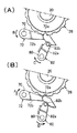
ここで、シフトレバー100が「P」ポジション以外のポジションから「P」ポジションにシフトされると、コントロールシャフト80は矢印Cの方向に回転し、パーキングレバー82のローラ部82bはパーキングロックポール72のカム面72b上を図6の右方に転動移動しながらパーキングロックポール72を矢印Bの方向(パーキングギヤ26側)に押圧する。これによりパーキングロックポール72(及びパーキングシャフト70)はリターンスプリング74の付勢力に抗して矢印Bの方向に回転し、パーキングロックポール72に設けられた前述の突起72aがパーキングギヤ26の外周歯に噛み合う(図6(A)参照)。これによりカウンタシャフト20は変速機ケース5に対してロックされ、左右のアクスルシャフト42,42に繋がる駆動輪(図示せず)は固定される。
【0028】
なお、このときパーキングロックポール72の突起72aがパーキングギヤ26の外周歯と噛合できずに外周歯上に乗り上げたときには、パーキングレバー82はパーキングロックポール72により矢印Dの方向に付勢された状態となり、リターンスプリング84を捻り状態にして「待ち」の状態となる。そして、その後、駆動輪が僅かに動いてカウンタシャフト20が矢印A若しくは矢印Bの方向に回転したとき、リターンスプリング84の付勢力によってパーキングレバー82は矢印Cの方向に回転移動し、パーキングロックポール72を矢印Bの方向へ押圧するので、パーキングロックポール72の突起72aはパーキングギヤ26の外周歯に噛み合うこととなる。
【0029】
一方、シフトレバー100が「P」ポジションから「P」以外のポジションにシフトされると、コントロールシャフト80は矢印Dの方向に回転し、パーキングレバー82はコントロールシャフト80上に設けられた前述のストッパにより押圧されてコントロールシャフト80と一体となって矢印Dの方向へ回転移動(揺動)する。このときパーキングレバー82のローラ部82bはパーキングロックポール72のカム面72b上を図6の左方に転動移動し、パーキングロックポール72がリターンスプリング74の付勢力により矢印Aの方向に移動するのを許容する。これによりパーキングロックポール72の突起72aはパーキングギヤ26の外周歯から離脱し(図6(B)参照)、カウンタシャフト20の変速機ケース5に対する固定(すなわち左右のアクスルシャフト42,42に繋がる駆動輪の固定)は解除される。
【0030】
次に、変速機1における動力伝達経路及び変速方式について説明する。電動モータMがバッテリBからの電力供給を受けて出力軸Sを回転させると、その回転動力は出力軸Sと結合された変速機1のメインシャフト10に伝達され、メインギヤ12及びカウンタギヤ22を介してカウンタシャフト20が回転する。また、これによりファイナルドライブギヤ24及びファイナルドリブンギヤ32を介してディファレンシャルケース30が回転し、最終的に左右のアクスルシャフト42,42に繋がる左右の駆動輪が回転する。
【0031】
また、この変速機1における変速は、電動モータMの回転数を変化させて行う。電動モータMは車体内の所定位置に設けられたコントロールユニット60と電気的に繋がっており、コントロールユニット60はアクセル開度センサ61、車速センサ62、ポジションセンサスイッチ63等から入力される信号に基づいて所要の判断をし、車両の走行状態に最適な出力が得られるように電動モータMの出力軸Sを回転させる制御を行う。ここで、アクセル開度センサ61は車両の運転席内に設けられたアクセルペダル(図示せず)の踏み込みによるアクセル開度(図示しないスロットルバルブの開度)を検出するセンサであり、車速センサ62はカウンタシャフト20の回転数から車両の走行速度を検出するセンサである。また、ポジションセンサスイッチ63は運転席内に設けられたシフトレバー100がシフトされている現在のポジションを検知するセンサであり、4つのシフトポジション「P」,「R」,「N」,「D」に対応するいずれかの信号をコントロールユニット60に出力する。
【0032】
ここで、シフトレバー100が「D」ポジションにシフトされている状態では、ポジションセンサスイッチ63はこれを検知して「D」ポジションに対応する信号をコントロールユニット60に出力する。この信号を受け取ったコントロールユニット60はアクセル開度センサ61により検出されたアクセル開度と車速センサ62により検出された車両の走行速度とにより、予め定めた(コントロールユニット60に記憶させた)変速特性図に基づいて最適な駆動力を算出し、このような駆動力が出力されるように電動モータMの制御を行う。なお、このとき電動モータMの出力軸Sの回転方向は車両を前進走行させる順方向である。
【0033】
また、シフトレバー100が「R」ポジションにシフトされている状態では、ポジションセンサスイッチ63はこれを検出して「R」ポジションに対応する信号をコントロールユニット60に出力する。この信号を受け取ったコントロールユニット60は電動モータMの出力軸Sを逆方向に回転させるが、このときの駆動力はシフトレバー100が「D」ポジションにシフトされて車両を前進走行させている場合とは異なり、或る一定の所定値が設定される。これは、後退走行時における車速は一般に小さく、走行開始時に必要な程度の一定の車速を設定することで十分であるからである。
【0034】
また、シフトレバー100が「N」ポジションにシフトされている状態では、ポジションセンサスイッチ63はこれを検出して「N」ポジションに対応する信号をコントロールユニット60に出力する。この信号を受け取ったコントロールユニット60は電動モータMを停止した状態に制御する。これにより電動モータMの出力軸Sはメインシャフト10に動力を与えず、外力により自由に回転しうる状態となる。
【0035】
また、シフトレバー100が「P」ポジションにシフトされている状態では、ポジションセンサスイッチ63はこれを検出して「P」ポジションに対応する信号をコントロールユニット60に出力する。この信号を受け取ったコントロールユニット60は上記シフトレバー100が「N」ポジションにシフトされている場合と同様、電動モータMを停止した状態に制御する一方で、上述のようにコントロールワイヤ104を介してコントロールシャフト80を図5中に示す矢印Cの方向へ回転させ、パーキングレバー82を介してパーキングロックポール72をパーキングギヤ26に押し付けてその突起72aをパーキングギヤ26の外周歯に噛合させる。
【0036】
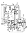
次に、この変速機1に適用されたワイヤ取付ピン脱落防止構造について説明する。図1は本変速機1に適用されたワイヤ取付ピン脱落防止構造の主要部を示す図であり、図3(A)における矢視I−Iより見た部分断面図に相当する。図1に示すように、本変速機1においては、コントロールシャフト80はその右端部と中央部とが左側ケース5bにより軸回り揺動自在に保持されており、その左端側の部分が左側ケース5bより外部(左方)に突出して延びている。また、コントロールレバー90はコントロールシャフト80における左側ケース5bの外部に突出した上記部分に位置しており、このコントロールレバー90に取り付けられたコントロールワイヤ104は、図1の紙面に垂直な方向に延びて設けられている。
【0037】
また、図3(A)及び図1に示すように、左側ケース5bの外面側には、コントロールシャフト80の左側ケース5bの外部に突出した部分を覆うようにコントロールレバーカバー110が取り付けられている。このコントロールレバーカバー110は、コントロールシャフト80における左側ケース5bの外部に突出した部分に取り付けられた諸部材(コントロールレバー90や後述するベアリング126、ポジションセンサスイッチ63など)を、車両の走行中に飛来してくる小石等から保護するために設けられる。また、コントロールレバーカバー110は、図3(A)及び図1に示すように(図8も参照)、複数のカバー取付ボルト112により左側ケース5bに対して着脱自在に取り付けられる。
【0038】
コントロールレバー90とコントロールワイヤ104とを連結する前述のワイヤ取付ピン92はコントロールレバー90に設けられたピン取付穴90a内に取り付けられる。このピン取付穴90aはコントロールレバー90の先端部をコントロールシャフト80の軸方向に延びて設けられており、したがってワイヤ取付ピン92はコントロールレバー90内をコントロールシャフト80の軸方向に延びて設けられる。
【0039】
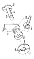
ワイヤ取付ピン92は、コントロールレバー90の左側ケース5b側(図1における紙面右側)からコントロールシャフト80の軸方向に沿ってピン取付穴90a内に挿着される。ワイヤ取付ピン92は一端側にピン取付穴90aの内径よりも大きい外形を有するほぼ円盤状のストッパ92aが設けられており、他端側には外周に沿って形成された溝部92bが設けられている。ワイヤ取付ピン92によるコントロールレバー90とコントロールワイヤ104との連結は、図7に示すように、コントロールワイヤ104の端部に設けられた輪状の金具104aにワイヤ取付ピン92を挿通させて行う。
【0040】
ピン取付穴90a内に挿着されたワイヤ取付ピン92の端部(図1における紙面左側の端部)にはクリップ94が取り付けられる。このクリップ94は、中央にワイヤ取付ピン92が貫通しうる大きさの穴94aが設けられるとともに、一方側の表面上にはこの穴94aの内周近傍まで先端部が延びた係止爪94bが設けられており、上記穴94a内にワイヤ取付ピン92が挿通されるようにクリップ94をワイヤ取付ピン92に押し付けたときには、係止爪94bがワイヤ取付ピン92の外周部に形成された上記溝部92b内に係止されて、ワイヤ取付ピン92がピン取付穴90a内に固定されるようになっている。
【0041】
また、本変速機1においては、図1に示すように、左側ケース5bとコントロールレバーカバー110とに間には、変速機ケース5内の振動がコントロールレバーカバー110に伝達されてコントロールレバーカバー110が共振するのを防止するための板状のラバーシート130が設けられている。また、コントロールレバーカバー110とカバー取付ボルト112との間にも同様の効果を奏するラバー部材114が設けられている。ここで、ラバーシート130は、左変速機ケース5bとコントロールレバーカバー110とにより挟持されてワイヤ取付ピン92と左側ケース5との間を延びており、電動モータMからの振動その他の原因によりクリップ94が緩んでワイヤ取付ピン92がコントロールレバー90から脱落しそうになった場合には、このワイヤ取付ピン92が当接するようになっている。このようにワイヤ取付ピン92がラバーシート130と当接することにより、ワイヤ取付ピン92はコントロールレバー90のピン取付穴90a内に留まるようになるので、結果としてワイヤ取付ピン92のコントロールレバー90からの(ピン取付穴90aからの)脱落が阻止されることとなる。
【0042】
また、図1に示すように、左側ケース5bとコントロールレバーカバー110とにより囲まれて形成される空間116内には、コントロールシャフト80の軸方向に延びて形成されたベアリング・センサ支持突起120が設けられている。このベアリング・センサ支持突起120の先端部には、固定ボルト124により固定されたベアリング・センサ支持部材122が設けられており、このベアリング・センサ支持部材122にはコントロールシャフト80の左側ケース5bの外部に突出した部分の先端部を軸回り揺動自在に保持するベアリング126が取り付けられている。また、上記ベアリング・センサ支持部材122には前述のポジションセンサスイッチ63が取り付けられており、コントロールシャフト80の回転(揺動)位置から現在のシフトレバー100のシフト位置を検出するようになっている。
【0043】
ここで、左側ケース5bの外部側に設けられる上記部品の取り付け手順を図1及び図8を参照しながら説明する。これは先ず、ラバーシート130に設けられた穴132を左側ケース5bに設けられた突起部に填め込んで、ラバーシート130を左側ケース5bに仮固定することから行う。なお、この段階ではコントロールレバー90はコントロールシャフト80にまだ取り付けられていない。ここでいうラバーシート130側の穴部132が填め込まれる左側ケース5b側の突起部とは、コントロールシャフト80の中央部を保持するコントロールシャフト支持部128や、上記ベアリング・センサ支持突起120などである。
【0044】
ラバーシート130を左側ケース5bに仮固定したら、コントロールワイヤ104が取り付けられた状態のコントロールレバー90をレバー取付ボルト86によりコントロールシャフト80に取り付ける。コントロールレバー90をコントロールシャフト80に取り付けたら、ベアリング126及びポジションセンサスイッチ63が取り付けられたベアリング・センサ支持部材122を固定ボルト124によりベアリング・センサ支持突起120に取り付ける。このときベアリング126によりコントロールシャフト80の端部が支持されるようにする。そして最後に、コントロールレバーカバー110をカバー取付ボルト112により左側ケース5bに取り付けて固定する。
【0045】
このように本変速機1に備えられたコントロールシャフトのワイヤ取付ピン脱落防止構造では、コントロールレバー90に取り付けられてコントロールシャフト80とコントロールワイヤ104とを連結するワイヤ取付ピン92が左側ケース5b側からコントロールレバー90に挿着されるようになっており、左側ケース5bとコントロールレバーカバー110との間に設置されたラバーシート130がワイヤ取付ピン92と左側ケース5bとの間に位置してワイヤ取付ピン92のコントロールレバー90からの脱落を阻止するようになっている。このため、従来のようにワイヤ取付ピンの抜け止めのための専用部品を変速機ケース等に取り付ける必要がなくなるので構成が簡単になるうえ、ラバーシート130は左側ケース5bとコントロールレバーカバー110との間に設置されるため、その取り付けは専用部品(カラー部材など)を左側ケース5bの所定箇所に取り付ける場合と比較して大変容易なものとなるので、従来に比して生産性及び整備性を向上させることができる。また、ここで用いられるラバーシート130は軽量であるため、従来のようにカラー部品をボルト等により変速機ケースに取り付ける構成よりも重量を軽減することができる。
【0046】
ここで、ラバーシート130は変速機ケース5側よりコントロールレバーカバー110側に伝わる振動を防止するためのものであり、このような振動低減ラバーは従来使用されていてワイヤ取付ピンの脱落防止のために新たに追加される部材ではないうえ、従来における振動低減用のラバー部材がコントロールレバーカバーを変速機ケースに取り付けるボルト(本変速機1におけるカバー取付ボルト112に相当)の取り付け位置ごとに設置される構成であったため、大きさの比較的小さいラバー部材が複数個必要であったのに比較し、本変速機1では大きなラバーシート130一つで済むためその取り扱いは大変容易なものとなる。また、このラバーシート130を左側ケース5bへの仮固定作業中に落下させてしまう虞は、従来の小さいラバー部材を変速機ケースへの取り付け中に落下させてしまう虞よりも遙かに小さく、生産性の向上を図ることができる。また、このラバーシート130は前述のように予め左側ケース5bに仮固定することができるので、その取り付けを簡単に行うことができる。更に、振動低減用として必要なラバーシート130がワイヤ取付ピン92の脱落防止用部材を兼ねることとなるので部品点数を低減することができ、製造工程を簡略化することができる。
【0047】
これまで本発明の好ましい実施形態について説明してきたが、本発明の範囲は上述の実施形態に示したものに限定されない。例えば、上述の実施形態においては、左側ケース5bとコントロールレバーカバー110との間に設置されてワイヤ取付ピン92と左側ケース5bとの間を延び、コントロールレバー90から脱落しそうになったワイヤ取付ピン92と当接してワイヤ取付ピン92のコントロールレバー90からの脱落を阻止する部材として、変速機ケース5側からコントロールレバーカバー110側に伝わる振動を低減する振動低減用のラバーシート130を利用していたが、これは必ずしもラバーシート130を利用しなくてもよく、別途板状の部材を設けるのであってもよい。
【0048】
また、上述の実施形態では、ラバーシート130に穴132を設けてこれを左側ケース5bに形成された突起部に填め込む構成であったが、これは必須の要件ではない。但し、このような構成とすることにより、コントロールレバーカバー110を左側ケース5bに取り付ける前に、ラバーシート130を左側ケース5bに仮固定することが可能となるので生産性及び整備性が向上するのは前述した通りである。また、上述の実施形態では、コントロールレバー90に取り付けられた状態のワイヤ取付ピン92はラバーシート130と所定間隔離間する配置構成をとっていたが、これは必須ではなく、両部材92,130が常時接触する配置構成を採るのであっても構わない。
【0049】
また、上述の実施形態においては、本発明に係るコントロールシャフトのワイヤ取付ピン脱落防止構造が、車両用変速機のパーキング機構に適用されるものであったが、これは一例であり、パーキング機構以外のワイヤコントロール式のシャフト部材に適用してもよい。更には、本発明の適用対象は車両用変速機に限定されるものではなく、その他の機械装置等におけるワイヤコントロール式のシャフト部材に適用することも可能である。
【0050】
【発明の効果】
以上説明したように、本発明に係るコントロールシャフトのワイヤ取付ピン脱落防止構造では、コントロールシャフトのレバー部に取り付けられてコントロールシャフトとワイヤとを連結するワイヤ取付ピンがシャフト保持体側からレバー部に挿着されるようになっており、シャフト保持体とカバー部材との間に設置された板状部材がワイヤ取付ピンとシャフト保持体との間に位置してワイヤ取付ピンのレバー部からの脱落を阻止するようになっている。このため、従来のようにワイヤ取付ピンの抜け止めのための専用部品をシャフト保持部材等に取り付ける必要がなくなるので構成が簡単になるうえ、板状部材はシャフト保持体とカバー部材との間に設置されるため、その取り付けは専用部品をシャフト保持体の所定箇所に取り付ける場合と比較して大変容易なものとなるので、従来に比して生産性及び整備性を向上させることができる。また、ここで用いられる板状部材は薄板でよいため、従来のようにカラー部品をボルト等によりシャフト保持体に取り付ける構成よりも重量を軽減することが可能である。
【0051】
また、本発明に係るコントロールシャフトのワイヤ取付ピン脱落防止構造では、板状部材に設けられた穴をシャフト保持体に設けられた突起部に填め込むことにより、カバー部材をシャフト保持体に取り付ける前に板状部材をシャフト保持体に仮固定できる構成とすることができる。このようにすれば板状部材の取り付けは大変簡単なものとなり、生産性及び整備性を更に向上させることができる。
【0052】
また、本発明に係るコントロールシャフトのワイヤ取付ピン脱落防止構造は、車両用変速機のパーキング機構に応用することができ、この場合には、シャフト保持体が車両用変速機の変速機ケースであり、コントロールシャフトがパーキングポールを車両用変速機に備えられたパーキングギヤの外周歯に噛合させるパーキングレバーの揺動用のシャフトであり、板状部材がシャフト保持体側からカバー部材側に伝わる振動を低減する振動低減用のラバーシートである構成となる。これにより上記効果を車両用変速機のパーキング機構において得ることが可能となるが、この場合には特に、振動低減用として必要なラバーシートがワイヤ取付ピンの脱落防止用部材を兼ねることとなるので部品点数を低減することができ、製造工程を簡略化することができる。
【図面の簡単な説明】
【図1】本発明の一実施形態に係るワイヤ取付ピン脱落防止構造が適用された車両用変速機におけるワイヤ取付ピン脱落防止構造の主要部を示す図である。
【図2】この車両用変速機の構成を示すスケルトン図である。
【図3】(A)はこの車両用変速機を左方より見た側面図であり、(B)は左側ケースを取り外した状態の変速機を左方より見た側面図である。
【図4】車両の運転席内に設けられたシフトレバーを斜め後上方から見た斜視図である。
【図5】パーキングギヤを中心にカウンタシャフトのロックに要する部材を取り出して描いた斜視図である。
【図6】上記車両用変速機に備えられたパーキング機構におけるカウンタシャフトのロック及びロック解除動作を説明するための図であり、(A)はパーキングロックポールの突起とパーキングギヤの外周歯とが噛合している状態を示し、(B)はパーキングロックポールの突起がパーキングギヤの外周歯から離脱した状態を示している。
【図7】ワイヤ取付ピン及びクリップによるコントロールワイヤとコントロールレバーとの連結の仕方を説明する図である。
【図8】上記変速機において、ラバーシート及びコントロールレバーカバーの変速機ケースへの取り付けの様子を示す図である。
【符号の説明】
1 車両用変速機
5 変速機ケース
5a 右側ケース
5b 左側ケース
10 メインシャフト
20 カウンタシャフト
26 パーキングギヤ
63 ポジションセンサスイッチ
70 パーキングシャフト
72 パーキングロックポール
80 コントロールシャフト
82 パーキングレバー
90 コントロールレバー
92 ワイヤ取付ピン
94 クリップ
104 コントロールワイヤ
110 コントロールレバーカバー
126 ベアリング
130 ラバーシート[0001]
BACKGROUND OF THE INVENTION
The present invention relates to a structure for preventing a wire attachment pin from falling off a control shaft used for a parking mechanism or the like in a vehicle transmission.
[0002]
[Prior art]
Conventionally known is a remote control mechanism for operating an operation target by swinging a control shaft held swingably around an axis with a wire.Vehicle transmissionUsed in a parking mechanism or the like.Vehicle transmissionThe parking mechanism has a configuration in which a protrusion of a parking pole is meshed with a parking gear fixed to an output shaft, and this remote control device is used to operate the parking pole (see, for example, Patent Document 1). .
[0003]
Conventionally, in an automatic transmission of a vehicle using an engine as a prime mover, a parking gear is fixed to a countershaft, and a parking lever for operating a parking pawl that meshes with an outer peripheral tooth of the parking gear extends in parallel with the countershaft. Attached to the control shaft. The control shaft is supported by the transmission case so as to be rotatable (swingable) about its axis. A control lever is provided at one end of the control shaft, and a shift lever provided in the driver's seat of the vehicle is provided on the control lever. A control wire connected to is provided. On the other hand, the other end of the control shaft is provided with a bearing that supports the control shaft and a position sensor switch that detects the shift position of the shift lever based on the rotational position of the control shaft. A control lever cover is attached to protect the members such as the control lever from pebbles coming into
[0004]
Here, the control wire is connected to the control lever by a wire mounting pin inserted into the control lever, and the wire mounting pin attached to the control lever is on the side opposite to the insertion side. It is fixed in the control lever by a clip attached from above. And even if the clip is loosened due to vibrations from the engine or other causes, the wire mounting pin will not fall off the control lever and the control wire will not come off from the control lever. The wire attachment pin is inserted into the control lever from the control lever cover side, and the distance between the control lever cover and the wire attachment pin is removed from the control lever to prevent the wire attachment pin from falling off the control lever. The wire mounting pin that is about to be kept at a distance that can come into contact with the control lever cover.
[0005]
Also, in a conventional vehicle (electric vehicle) transmission that uses an electric motor as a prime mover, the parking gear is fixed to the counter shaft, and the parking lever that operates the parking pole that meshes with the outer peripheral teeth of the parking gear is the transmission. It is attached to the control shaft supported by the case. One end side of the control shaft protrudes outward from the transmission case (the side opposite to the prime mover), and a bearing for supporting the control shaft is provided at the end of the protruding portion. Further, a control lever is provided between the bearing and the transmission case, and a position sensor switch is also provided at the end of the control shaft on the bearing side. A control lever cover for protecting the control lever and the like is attached to the outside of the transmission case by a plurality of cover mounting bolts. The joint between the transmission case and the control lever cover and the control lever cover and the cover mounting bolt are connected to each other. In the meantime, a rubber member is installed to prevent the control lever cover from resonating by reducing vibration transmitted from the transmission case side to the control lever cover side.
[0006]
[Patent Document 1]
JP 2001-295922 A
[Patent Document 2]
JP 2001-253324 A
[Patent Document 3]
JP 2001-341619 A
[0007]
[Problems to be solved by the invention]
By the way, in a vehicle transmission mounted on an electric vehicle, an electric motor as a prime mover is used.motorTherefore, in order to make the entire transmission compact, it is necessary to dispose the parking mechanism centered on the control shaft inside the outer shape of the electric motor. Further, when such an arrangement is adopted, as described above, the control shaft must be protruded on the side opposite to the prime mover side of the transmission case, and a control lever must be provided there. In this respect, the prime mover that can arrange the control lever connected to the control wire on the prime mover side, can arrange the control lever on one end side of the control shaft, and the bearing and position sensor switch on the other end side. This is different from the case of a vehicle transmission that is an engine. As in the case of a vehicle transmission using this electric motor as a prime mover, in a configuration in which a control lever, a bearing, and a position sensor switch are all arranged on one end side of the control shaft, a bearing and Since it is necessary to provide a position sensor switch, the control lever cannot be brought close to the control lever cover. As a result, the control lever cover has a function to prevent the pin from falling off as in the case where the prime mover is an engine. I couldn't make it.
[0008]
In order to avoid such an inconvenience, there is a method of providing a collar member, which is a dedicated component for preventing pin dropout, in the transmission case. This is a wire mounting pin that attaches the control wire to the control lever, and is inserted into the control lever along the axial direction of the control shaft, and the collar member is arranged in the direction of removal of the wire mounting pin. It is. However, in the case of adopting such a configuration, since it is difficult to attach the collar member, there is an increase in cost required for manufacturing, and there is a problem that the maintainability is also inferior. Furthermore, the control shaft changes its rotational (swinging) position depending on the position of the shift lever, and the wire mounting pin attached to the control lever is moved to positions “P (parking)”, “R (reverse)”, Either “N (neutral)” or “D (forward)” is taken, but in order to make the collar member always face the wire mounting pin regardless of the position of the wire mounting pin, it is considerably large. A special color member is required.AttachSince the bolt for this purpose also becomes large, there also existed a problem that a weight increased.
[0009]
The present invention has been made in view of such problems, and has a configuration that is simpler than that of the prior art, can improve productivity and maintainability, and can reduce weight. It is an object of the present invention to provide a structure for preventing a wire attachment pin from falling off a control shaft.
[0010]
[Means for Solving the Problems]
In order to achieve such an object, the control shaft wire attachment pin drop-off preventing structure according to the present invention is held by a shaft holding body and the shaft holding body so as to be swingable around an axis, and one end side is outside the shaft holding body. A control shaft having a protruding and extending lever portion extending in the off-axis direction at the protruding portion, a cover member attached to cover the protruding portion of the control shaft on the outer surface side of the shaft holder, and the shaft Inserted into the lever part from the holder side,Wire mounting pins provided extending in the axial direction of the control shaft;It is connected to the lever part via the wire mounting pin, and is installed between the shaft holding body and the cover member to swing the control shaft around the axis when tension is applied, and the wire mounting pin and shaft holding It consists of a plate-like member that extends between the body and abuts against the wire attachment pin to prevent the wire attachment pin from coming off from the lever portion.
[0011]
In the control shaft wire attachment pin drop prevention structure according to the present invention, the wire attachment pin attached to the lever portion of the control shaft and connecting the control shaft and the wire is inserted into the lever portion from the shaft holding body side. And a plate-like member installed between the shaft holder and the cover member is positioned between the wire attachment pin and the shaft holder to prevent the wire attachment pin from coming off from the lever portion. . For this reason, it is not necessary to attach a dedicated part for preventing the wire attachment pin from being attached to the shaft holding member or the like as in the prior art, so that the configuration is simplified and the plate-like member is interposed between the shaft holding body and the cover member. Since it is installed, the attachment becomes very easy compared with the case where the dedicated part is attached to a predetermined portion of the shaft holder, so that productivity and maintainability can be improved as compared with the conventional case. Further, since the plate-like member used here may be a thin plate (not limited to a metal, it may be a rubber member), so that the weight is higher than a conventional configuration in which a color component is attached to a shaft holder with bolts or the like. It can be reduced.
[0012]
In the control shaft wire attachment pin drop-off preventing structure according to the present invention, the cover member is attached to the shaft holder by fitting the hole provided in the plate-like member into the protrusion provided in the shaft holder. The plate member can be temporarily fixed to the shaft holder. If it does in this way, attachment of a plate-shaped member will become very simple, and productivity and maintainability can be improved further.
[0013]
Further, the control shaft wire attachment pin drop-off preventing structure according to the present invention can be applied to a parking mechanism of a vehicle transmission, and in this case, the shaft holder is a transmission case of the vehicle transmission. The control shaft is a shaft for swinging the parking lever that meshes the parking pole with the outer peripheral teeth of the parking gear provided in the vehicle transmission, and the plate-like member reduces vibration transmitted from the shaft holder side to the cover member side. The configuration is a rubber sheet for vibration reduction. As a result, the above-described effect can be obtained in the parking mechanism of the vehicle transmission. In this case, in particular, the rubber seat necessary for vibration reduction also serves as a member for preventing the wire attachment pin from falling off. The number of parts can be reduced, and the manufacturing process can be simplified.
[0014]
DETAILED DESCRIPTION OF THE INVENTION
Hereinafter, preferred embodiments of the present invention will be described with reference to the drawings. FIG. 2 illustrates a control shaft wire attachment pin drop-off preventing structure according to an embodiment of the present invention.Vehicle transmissionIt is a skeleton figure which shows the structure of. As shown in this figure, according to this embodimentVehicle transmission1 (hereinafter abbreviated as “transmission”) 1 uses as its prime mover an electric motor M that receives power supplied from a battery B mounted on a vehicle (not shown) and applies rotational power to an output shaft S. Of the type mounted onVehicle transmissionIt is.
[0015]
The
[0016]
The
[0017]
Inside the
[0018]
As shown in FIG. 2, the
[0019]
FIG. 4 is a perspective view of the
[0020]
Further, as shown in FIG. 2, a
[0021]
FIG. 5 is a perspective view in which the members required for locking the
[0022]
Here, the parking lock pole 72 (that is, the parking shaft 70) is moved in the direction of the arrow A shown in FIG. 5 (the direction away from the parking gear 26) by the coiled
[0023]
A
[0024]
The
[0025]
The other end of the
[0027]
Here, when the
[0028]
At this time, when the
[0029]
On the other hand, when the
[0030]
Next, a power transmission path and a transmission system in the transmission 1 will be described. When the electric motor M receives power supply from the battery B and rotates the output shaft S, the rotational power is transmitted to the
[0031]
Further, the speed change in the transmission 1 is performed by changing the rotation speed of the electric motor M. The electric motor M is electrically connected to a
[0032]
When the
[0033]
Further, when the
[0034]
Further, when the
[0035]
In the state where the
[0036]
Next, the wire attachment pin drop-off preventing structure applied to the transmission 1 will be described. FIG. 1 is a view showing a main part of a wire attachment pin drop-off preventing structure applied to the present transmission 1, and corresponds to a partial cross-sectional view seen from an arrow II in FIG. As shown in FIG. 1, in the present transmission 1, the
[0037]
Further, as shown in FIGS. 3A and 1, a
[0038]
The
[0039]
The
[0040]
A
[0041]
Further, in the present transmission 1, as shown in FIG. 1, vibration in the
[0042]
As shown in FIG. 1, a bearing /
[0043]
Here, the attachment procedure of the above components provided on the outside of the
[0044]
After the
[0045]
Thus, in the control shaft wire attachment pin drop prevention structure provided in the present transmission 1, the
[0046]
Here, the
[0047]
The preferred embodiments of the present invention have been described so far, but the scope of the present invention is not limited to those shown in the above-described embodiments. For example, in the above-described embodiment, the wire attachment pin that is installed between the
[0048]
In the above-described embodiment, the
[0049]
Further, in the above-described embodiment, the structure for preventing the wire attachment pin from falling off of the control shaft according to the present invention,Vehicle transmissionHowever, this is only an example, and may be applied to a wire control type shaft member other than the parking mechanism. Furthermore, the subject of application of the present invention isVehicle transmissionHowever, the present invention can be applied to a wire control type shaft member in other mechanical devices.
[0050]
【The invention's effect】
As described above, in the control shaft wire attachment pin drop prevention structure according to the present invention, the wire attachment pin that is attached to the lever portion of the control shaft and connects the control shaft and the wire is inserted into the lever portion from the shaft holding body side. A plate-like member installed between the shaft holder and the cover member is positioned between the wire attachment pin and the shaft holder to prevent the wire attachment pin from falling off the lever portion. It is supposed to be. For this reason, it is not necessary to attach a dedicated part for preventing the wire attachment pin from being attached to the shaft holding member or the like as in the prior art, so that the configuration is simplified and the plate-like member is interposed between the shaft holding body and the cover member. Since it is installed, the attachment becomes very easy compared with the case where the dedicated part is attached to a predetermined portion of the shaft holder, so that productivity and maintainability can be improved as compared with the conventional case. Further, since the plate-like member used here may be a thin plate, it is possible to reduce the weight as compared with the conventional configuration in which the color component is attached to the shaft holder with bolts or the like.
[0051]
In the control shaft wire attachment pin drop-off preventing structure according to the present invention, the cover member is attached to the shaft holder by fitting the hole provided in the plate-like member into the protrusion provided in the shaft holder. The plate member can be temporarily fixed to the shaft holder. If it does in this way, attachment of a plate-shaped member will become very simple, and productivity and maintainability can be improved further.
[0052]
Further, the control shaft wire attachment pin drop-off preventing structure according to the present invention can be applied to a parking mechanism of a vehicle transmission, and in this case, the shaft holder is a transmission case of the vehicle transmission. The control shaft is a shaft for swinging the parking lever that meshes the parking pole with the outer peripheral teeth of the parking gear provided in the vehicle transmission, and the plate-like member reduces vibration transmitted from the shaft holder side to the cover member side. The configuration is a rubber sheet for vibration reduction. As a result, the above-described effect can be obtained in the parking mechanism of the vehicle transmission. In this case, in particular, the rubber seat necessary for vibration reduction also serves as a member for preventing the wire attachment pin from falling off. The number of parts can be reduced, and the manufacturing process can be simplified.
[Brief description of the drawings]
FIG. 1 shows a structure for preventing a wire mounting pin from dropping according to an embodiment of the present invention.Vehicle transmissionIt is a figure which shows the principal part of the wire attachment pin drop-off prevention structure.
[Figure 2]Vehicle transmissionIt is a skeleton figure which shows the structure of.
Figure 3 (A) shows thisVehicle transmissionFIG. 5B is a side view of the transmission with the left side case removed, viewed from the left side.
FIG. 4 is a perspective view of a shift lever provided in the driver's seat of the vehicle as viewed obliquely from above.
FIG. 5 is a perspective view illustrating a member required for locking the counter shaft with the parking gear as a center.
FIG. 6Vehicle transmission(A) shows a state in which the protrusion of the parking lock pole and the outer peripheral teeth of the parking gear mesh with each other. B) shows a state in which the protrusion of the parking lock pole is detached from the outer peripheral teeth of the parking gear.
FIG. 7 is a view for explaining how to connect a control wire and a control lever by a wire mounting pin and a clip.
FIG. 8 is a diagram showing how the rubber seat and the control lever cover are attached to the transmission case in the transmission.
[Explanation of symbols]
1Vehicle transmission
5 Transmission case
5a Right case
5b left side case
10 Main shaft
20 Countershaft
26 Parking gear
63 Position sensor switch
70 Parking shaft
72 Parking lock pole
80 Control shaft
82 Parking lever
90 Control lever
92 Wire mounting pin
94 clips
104 Control wire
110 Control lever cover
126 Bearing
130 Rubber sheet
Claims (3)
前記シャフト保持体により軸回り揺動自在に保持されて一端側が前記シャフト保持体の外部に突出して延びるとともに、この突出した部分に軸外方向に延びるレバー部が設けられたコントロールシャフトと、
前記シャフト保持体の外面側に前記コントロールシャフトの前記突出した部分を覆うように取り付けられたカバー部材と、
前記シャフト保持体側より前記レバー部に挿着され、前記コントロールシャフトの軸方向に延びて設けられたワイヤ取付ピンと、
前記ワイヤ取付ピンを介して前記レバー部に連結され、張力が与えられたときに前記コントロールシャフトを軸回りに揺動移動させるワイヤと、
前記シャフト保持体と前記カバー部材との間に設置されて前記ワイヤ取付ピンと前記シャフト保持体との間を延び、前記ワイヤ取付ピンと当接することにより前記ワイヤ取付ピンの前記レバー部からの脱落を阻止する板状部材とからなることを特徴とするコントロールシャフトのワイヤ取付ピン脱落防止構造。A shaft holder,
A control shaft that is held by the shaft holder so as to be swingable about an axis and has one end projecting and extending outside the shaft holder, and a lever portion extending in the off-axis direction is provided on the projecting portion;
A cover member attached to the outer surface side of the shaft holder so as to cover the protruding portion of the control shaft;
A wire mounting pin that is inserted into the lever portion from the shaft holding body side and extends in the axial direction of the control shaft;
A wire that is connected to the lever portion via the wire mounting pin and swings and moves the control shaft about an axis when tension is applied;
It is installed between the shaft holder and the cover member, extends between the wire attachment pin and the shaft holder, and prevents the wire attachment pin from coming off from the lever portion by contacting the wire attachment pin. A structure for preventing a wire mounting pin from falling off a control shaft, characterized by comprising a plate-like member.
Priority Applications (1)
| Application Number | Priority Date | Filing Date | Title |
|---|---|---|---|
| JP2002328287A JP4187509B2 (en) | 2002-11-12 | 2002-11-12 | Control shaft wire mounting pin fall-off prevention structure |
Applications Claiming Priority (1)
| Application Number | Priority Date | Filing Date | Title |
|---|---|---|---|
| JP2002328287A JP4187509B2 (en) | 2002-11-12 | 2002-11-12 | Control shaft wire mounting pin fall-off prevention structure |
Publications (3)
| Publication Number | Publication Date |
|---|---|
| JP2004162779A JP2004162779A (en) | 2004-06-10 |
| JP2004162779A5 JP2004162779A5 (en) | 2005-06-30 |
| JP4187509B2 true JP4187509B2 (en) | 2008-11-26 |
Family
ID=32806628
Family Applications (1)
| Application Number | Title | Priority Date | Filing Date |
|---|---|---|---|
| JP2002328287A Expired - Fee Related JP4187509B2 (en) | 2002-11-12 | 2002-11-12 | Control shaft wire mounting pin fall-off prevention structure |
Country Status (1)
| Country | Link |
|---|---|
| JP (1) | JP4187509B2 (en) |
Families Citing this family (3)
| Publication number | Priority date | Publication date | Assignee | Title |
|---|---|---|---|---|
| JP4784363B2 (en) * | 2006-03-28 | 2011-10-05 | いすゞ自動車株式会社 | Parking lock device for transmission |
| JP4713630B2 (en) * | 2008-12-22 | 2011-06-29 | 日信工業株式会社 | Operation lever mounting structure of hydraulic master cylinder device |
| DE102009048916A1 (en) | 2009-10-10 | 2011-04-14 | Minebea Co., Ltd. | Fluid-dynamic bearing e.g. roller bearing, system for rotary mounting of spindle motor, has shaft arranged in bush, and bearing gap including open end sealed by seal gap, where opening of seal gap is aligned in pointed angle towards axis |
-
2002
- 2002-11-12 JP JP2002328287A patent/JP4187509B2/en not_active Expired - Fee Related
Also Published As
| Publication number | Publication date |
|---|---|
| JP2004162779A (en) | 2004-06-10 |
Similar Documents
| Publication | Publication Date | Title |
|---|---|---|
| JP5002142B2 (en) | Deceleration drive | |
| US6007447A (en) | Transmission unit for the disk motor of an electromotive bicycle | |
| JPH0539865A (en) | Shift drum driving mechanism for transmission | |
| WO2018173695A1 (en) | Power unit for electrically assisted vehicle | |
| JP3699371B2 (en) | In-wheel motor drive unit and hybrid system | |
| JP4187509B2 (en) | Control shaft wire mounting pin fall-off prevention structure | |
| JP2018141549A (en) | Differential device | |
| JP4414737B2 (en) | Control shaft wire attachment pin fall-off prevention structure | |
| JP2018159444A (en) | Power unit for electric power-assisted vehicle and method of assembling the same | |
| US6536576B2 (en) | Parking lock device for a saddle riding type vehicle | |
| JP6565457B2 (en) | Manual release mechanism for vehicle parking lock device | |
| US5269273A (en) | Throttle body with an actuator for autodrive | |
| JP6358183B2 (en) | Manual release mechanism for vehicle parking lock device | |
| CN108506432B (en) | Transmission mechanism for single-arm frame and hub assembly applied to transmission mechanism | |
| JPH1081292A (en) | Drive unit of bicycle with auxiliary power | |
| JP3736870B2 (en) | Vehicle parking device | |
| JPH073017Y2 (en) | Engine starter | |
| JPH02189270A (en) | Electric power steering system | |
| JP5013589B2 (en) | Vehicle engine mount structure | |
| JP4155437B2 (en) | Structure and assembly method of shift inversion mechanism of transmission | |
| WO2018173696A1 (en) | Power unit for electric vehicle | |
| JP2588385Y2 (en) | Positioning device for shift operation lever for automobile | |
| JPS6210823Y2 (en) | ||
| JPH06307506A (en) | Electro-magnetic clutch | |
| JPH06200991A (en) | Differential lock device |
Legal Events
| Date | Code | Title | Description |
|---|---|---|---|
| A521 | Written amendment |
Free format text: JAPANESE INTERMEDIATE CODE: A523 Effective date: 20041012 |
|
| A621 | Written request for application examination |
Free format text: JAPANESE INTERMEDIATE CODE: A621 Effective date: 20041012 |
|
| A977 | Report on retrieval |
Free format text: JAPANESE INTERMEDIATE CODE: A971007 Effective date: 20070326 |
|
| A131 | Notification of reasons for refusal |
Free format text: JAPANESE INTERMEDIATE CODE: A131 Effective date: 20080111 |
|
| A521 | Written amendment |
Free format text: JAPANESE INTERMEDIATE CODE: A523 Effective date: 20080227 |
|
| TRDD | Decision of grant or rejection written | ||
| A01 | Written decision to grant a patent or to grant a registration (utility model) |
Free format text: JAPANESE INTERMEDIATE CODE: A01 Effective date: 20080815 |
|
| A01 | Written decision to grant a patent or to grant a registration (utility model) |
Free format text: JAPANESE INTERMEDIATE CODE: A01 |
|
| A61 | First payment of annual fees (during grant procedure) |
Free format text: JAPANESE INTERMEDIATE CODE: A61 Effective date: 20080909 |
|
| R150 | Certificate of patent or registration of utility model |
Ref document number: 4187509 Country of ref document: JP Free format text: JAPANESE INTERMEDIATE CODE: R150 Free format text: JAPANESE INTERMEDIATE CODE: R150 |
|
| FPAY | Renewal fee payment (event date is renewal date of database) |
Free format text: PAYMENT UNTIL: 20110919 Year of fee payment: 3 |
|
| FPAY | Renewal fee payment (event date is renewal date of database) |
Free format text: PAYMENT UNTIL: 20110919 Year of fee payment: 3 |
|
| FPAY | Renewal fee payment (event date is renewal date of database) |
Free format text: PAYMENT UNTIL: 20120919 Year of fee payment: 4 |
|
| FPAY | Renewal fee payment (event date is renewal date of database) |
Free format text: PAYMENT UNTIL: 20120919 Year of fee payment: 4 |
|
| FPAY | Renewal fee payment (event date is renewal date of database) |
Free format text: PAYMENT UNTIL: 20130919 Year of fee payment: 5 |
|
| FPAY | Renewal fee payment (event date is renewal date of database) |
Free format text: PAYMENT UNTIL: 20140919 Year of fee payment: 6 |
|
| LAPS | Cancellation because of no payment of annual fees |