JP4186593B2 - DC brushless motor and DC pump provided with the same - Google Patents
DC brushless motor and DC pump provided with the same Download PDFInfo
- Publication number
- JP4186593B2 JP4186593B2 JP2002329436A JP2002329436A JP4186593B2 JP 4186593 B2 JP4186593 B2 JP 4186593B2 JP 2002329436 A JP2002329436 A JP 2002329436A JP 2002329436 A JP2002329436 A JP 2002329436A JP 4186593 B2 JP4186593 B2 JP 4186593B2
- Authority
- JP
- Japan
- Prior art keywords
- magnetic pole
- brushless motor
- pole position
- magnet rotor
- position sensor
- Prior art date
- Legal status (The legal status is an assumption and is not a legal conclusion. Google has not performed a legal analysis and makes no representation as to the accuracy of the status listed.)
- Expired - Fee Related
Links
Images


Landscapes
- Brushless Motors (AREA)
- Permanent Magnet Type Synchronous Machine (AREA)
- Structures Of Non-Positive Displacement Pumps (AREA)
Description
【0001】
【発明の属する技術分野】
本発明は、磁極位置センサの感度を向上させ、薄型で長寿命、高効率のDCブラシレスモータ及びそれを備えたDCポンプに関する。
【0002】
【従来の技術】
電機子は固定子鉄心に巻線を巻いて使用されるため、どうしても物理的にスペースが必要で機構上大型化する傾向があり、最近では小型化、さらに薄型化に対する要求が高まりつつある。
【0003】
以下に薄型化を目的とした従来のDCブラシレスモータについて、図4を用いて説明する。図4は従来のDCブラシレスモータの構成図である。図4において、電機子108の中央付近にドライバIC113が位置するように基板112上にドライバIC113を配し、シ−ルド板114を基板112の下に配設した後、この基板112にコイル110が巻装された電機子108を固定し、ロ−タフレ−ム107に保持されたマグネットロータ106に対向するように電機子108を配し、直流ブラシレスモ−タを構成している。また、この基板112上には、マグネットロータ106の磁極位置を検出する磁極位置センサ115も配置され、この磁極位置センサ115の出力信号を受けて、ドライバIC113は電機子108の巻線110に流す電流を制御する。これによって電機子108が電磁石となり、マグネットロータ106の磁極との吸引と反発が発生し、マグネットロータ106に回転トルクが発生する。
【0004】
この構成により、ドライバIC113からのパタ−ン配線が容易にでき、基板112に対するパタ−ン配線の面積を小さくすることができるため、基板112の外形を小さくすることができ直流ブラシレスモ−タの小型化ができる。また、電機子108に巻装されているコイルからの制約がなくなり、より薄型な直流ブラシレスモ−タを実現することができるものである(例えば特許文献1参照)。
【0005】
【特許文献1】
特許第3106582号公報
【0006】
【発明が解決しようとする課題】
しかしながら、上記従来のDCブラシレスモータの構成では、磁極位置センサ115とドライバIC113実装用の基板112を、固定子鉄心のコイルエンドから適当なギャップを設けて配置するため、コイルエンドと基板側の厚みによりモータの厚みが決定されるという制約を受け、しかも基板112へ電気を供給するためにリード線111を必要とし、そのリード線111の外径寸法も無視できずモータの薄型化が図れない課題を有していた。なお、116はコネクタである。
【0007】
また、この従来のDCブラシレスモータは、薄型化を図る必要からマグネットロータの長さが固定子鉄心の長さより充分でなく、このため漏れ磁束から磁極位置を確実に検出できず、安定したモータ性能が得られないという課題を有していた。
【0008】
さらに、従来のDCポンプは薄型でなく、しかも安定したポンプ性能を得ることが難しいものであった。
【0009】
そこで本発明は、薄型で、マグネットロータの磁極位置を確実に検出して安定したモータ性能のDCブラシレスモータを提供することを目的としている。
【0010】
また、本発明は、薄型で、マグネットロータの磁極位置を確実に検出して安定した出力のDCポンプを提供することを目的としている。
【0011】
【課題を解決するための手段】
上記課題を解決するために本発明は、複数のティースの先端にそれぞれ突極を有する固定子鉄心と、突極の外周側で回転するマグネットロータと、ティースに巻かれた巻線コイルと突極とに囲まれた位置に配置されて、マグネットロータの磁極位置を検出する磁極位置センサと、磁極位置センサからの出力信号によって巻線コイルに流す電流を制御するドライバICとを備えたDCブラシレスモータであって、少なくとも磁極位置センサとドライバICを実装したフレキシブル基板が、巻線コイルが巻かれていない位置で固定子鉄心に取り付けられるとともに、そのリード部がモータ側面形状に沿って屈曲自在に外部に引き出され、、且つフレキシブル基板が突極側面からマグネットロータと対向する面に屈曲され、屈曲された部分に磁極位置センサの検出面をマグネットロータに対向させた状態で取り付けたことを特徴とする。
【0012】
これにより、薄型で、マグネットロータの磁極位置を確実に検出して安定したモータ性能にすることができる。
【0013】
【発明の実施の形態】
上記課題を解決するためになされた請求項1の発明は、複数のティースの先端にそれぞれ突極を有する固定子鉄心と、突極の外周側で回転するマグネットロータと、ティースに巻かれた巻線コイルと突極とに囲まれた位置に配置されて、マグネットロータの磁極位置を検出する磁極位置センサと、磁極位置センサからの出力信号によって巻線コイルに流す電流を制御するドライバICとを備えたDCブラシレスモータであって、少なくとも磁極位置センサとドライバICを実装したフレキシブル基板が、巻線コイルが巻かれていない位置で固定子鉄心に取り付けられるとともに、そのリード部がモータ側面形状に沿って屈曲自在に外部に引き出され、且つフレキシブル基板が突極側面からマグネットロータと対向する面に屈曲され、屈曲された部分に磁極位置センサの検出面をマグネットロータに対向させた状態で取り付けたことを特徴とするDCブラシレスモータであり、フレキシブル基板のリード部を使うのでドライバICに電気を給電するためのリード線が不要となり、薄いフレキシブル基板が屈曲できるので巻線コイルを避けた位置で固定子鉄心に取り付けることが可能であり、DCブラシレスモータの薄型化が飛躍的に図れるとともに、薄いため機器に組込む際の自由度が向上するという作用を有する。
【0014】
更に、DCブラシレスモータの薄型化を図るとき、マグネットロータの漏れ磁束で磁極位置を検出するのではなく、主磁束で検出するため磁極位置の検出感度が向上し、モータ性能の安定化が図れる。
【0015】
請求項2の発明は、請求項1記載のDCブラシレスモータを駆動部とし、マグネットロータを水封したケーシングを備えたDCポンプであって、固定子鉄心および巻線コイルからなる電機子の形成する磁界によってマグネットロータがケーシング内で回転されることを特徴とするDCポンプであり、DCポンプを薄型化できるとともに長寿命を実現でき、磁極位置センサの感度も向上し、ポンプ性能が安定する。
【0016】
以下、フレキシブル基板を設けたDCブラシレスモータの基本構成について図1を用いて説明する。
【0017】
(基本構成)
図1(a)は4極4スロットのDCブラシレスモータの基本構成図であり、図1(b)は(a)のDCブラシレスモータのA−A断面図である。図1(a),(b)において、1は固定子鉄心、1aは固定子鉄心1の突極、2はティース、3は巻線コイル、4はマグネットロータ、5は電機子、6は磁極位置(磁極の切れ目)、7は磁極位置センサ、8はドライバIC、9はFPC基板(本発明のフレキシブル基板)、9aはFPCリード部、10は補強板、11は屈曲部、12はコイルエンド長である。
【0018】
この固定子鉄心1の素材としては、鉄損を低減しモータ効率を向上するために、透磁率が大きく、厚さがt=0.2〜0.5mm程度の珪素鋼鈑が好適である。固定子鉄心1はこの鋼鈑を複数枚積層されて構成される。この固定子鉄心1の中心から放射状にのびる腕の部分がティース2であり、ティース2の部分に巻線が施され、巻線コイル3が形成される。巻線コイル3の巻線材は一般的に銅線に薄い絶縁皮膜を施したものが使用される。
【0019】
ところで、マグネットロータ4と対向する突極1aは、できるだけマグネットロータ4のマグネットからの磁束を固定子鉄心1内に取り込むと同時に、巻線コイル3の巻線可能な部分を確保するため、ティース2と比較して幅広い形状となっている。電機子5はこのような固定子鉄心1とそれに巻かれた巻線コイル3とから構成される。また、マグネットロータ4のマグネットは永久磁石となりうるフェライトや金属系磁性体(SmCo等)等がよい。
【0020】
マグネットロータ4は、巻線コイル3に電流を流すことで各ティース2に順に形成される電磁石の磁力によって吸引または反発され、磁界の方向にトルクが発生し、電機子5周りに回転を始める。このときトルクを効率よく発生させるには、巻線コイル3に流す電流の向きをタイミングよく切り替える必要がある。そこで、この切り替えのタイミングを正確にするため、磁極位置センサ7が設けられ、これがマグネットロータ4の磁極位置(磁極の切れ目)6を検出し、タイミング信号として出力する。この磁極位置センサ7が発生したタイミング信号は、ドライバIC8に入力され、ドライバIC8はこのタイミング信号に基づいて巻線コイル3に流す電流方向を切り替える。これにより4つの突極1aに発生する電磁石の磁極の極性がそれぞれ切り替わる。
【0021】
ところで、磁極位置センサ7とドライバIC8は、屈曲可能なFPC基板9に実装されている。このFPC基板9の材質としては耐熱性のあるポリイミド(厚さt=0.1mm程度)等が適当である。また、磁極位置センサ7とドライバIC8等の電子部品が実装される部分には、FPC基板9の実装面と反対側に補強板10を貼り合わすのが好適である。この補強板10の材質は一般的に耐熱性を持つガラス繊維入りのエポキシ基板(通称ガラエポ基板)、もしくはFPC基板9と同じポリイミドを使うのがよく、厚さは0.2〜0.3mm程度が適当である。
【0022】
このDCブラシレスモータで最も特徴的な部分はこのFPC基板9の形状と電機子5上のレイアウトにある。図1(a)に示すように、FPC基板9の形状は徳利形である。磁極位置センサ7は、磁極位置6を検出するために、漏れ磁束を検出するため可能な限りマグネットロータ4に近づける必要があり、徳利の口側部分の上に配置される。またドライバIC8は磁極位置センサ7より数倍の実装面積を必要とするため、固定子鉄心1の中心部分に実装される。また、モータの薄型化するため、コイルエンド長12に影響しないように巻線コイル3の位置を避け、FPC基板9の形状も徳利形で、これがベルト状のFPCリード部9aに繋がった形状となっている。すなわち、FPC基板9でドライバIC8に電気を給電するため、従来必要だったリード線を実装する必要がなく、リード線の外径寸法よりはるかに薄いFPC基板9を使い、しかも巻線コイル3を避けて固定子鉄心1(補強板10を含む)上にFPC基板9を配設するために、屈曲部11で巻線コイル3等のモータ側面形状に沿って屈曲(90°程度まで屈曲可能)させてFPCリード部9aを引き出すことができ、モータの薄型化が図れる。
【0023】
このように図1のDCブラシレスモータにおいては、ドライバIC8や磁極位置センサ7等が実装されたFPC基板9を電機子5上にレイアウトすることで、従来の技術のように、コイルエンド長とギャップ、さらに基板の厚みと、補強板の厚み、実装部品の高さ、これに加えてドライバICに給電するためのリード線の外径寸法とを加算した寸法をDCブラシレスモータの厚みとする必要はない。すなわち、図1のDCブラシレスモータでは、固定子鉄心1の厚みにFPC基板9と補強板10を含めた厚みと、実装部品の高さを加算した寸法が、DCブラシレスモータの厚みを決定することになる。これにより、電源電圧5V、最大出力200mWのDCブラシレスモータを外径20mmの固定子鉄心1で4mmの厚みとすることができた。なお、この厚み4mmというのは、従来の技術では7.5mm必要であったものであり、図1の基本構成のDCブラシレスモータはこれをほぼ半分の厚みとし、大幅な薄型化を実現するものである。
【0024】
(実施の形態1)
図2,図3を用いて本発明の実施の形態1について説明する。実施の形態1は、図1のDCブラシレスモータにおいて、マグネットロータ4の磁極位置検出の感度を向上させるものである。図2(a)は本発明の実施の形態1における4極4スロットのDCブラシレスモータの構成図、図2(b)は(a)のDCブラシレスモータのA−A断面図である。なお、図1と同一符号の構成に関しては同一内容であるから、説明を割愛する。
【0025】
実施の形態1のDCブラシレスモータは、図1と同様、第1の屈曲部11で巻線コイル3に沿って屈曲させてFPC基板9のFPCリード部9aを引き出すとともに、磁極位置センサ7とドライバIC8との間に更に第2の屈曲部11を設けている。すなわち、FPC基板9は、第2の屈曲部11で屈曲され、この部分に磁極位置センサ7の検出面がマグネットロータ4に対向させた状態で取り付けられる。当然ながら、部品を実装した部分の補強板10は第2の屈曲部11の部分では除かれる。これにより第2の屈曲部11を設け易くしている。そして、この磁極位置センサ7の検出面をマグネットロータ4に対向することで、磁極位置センサ7の感度が格段に向上する。この感度向上を(表1)を用いて説明する。(表1)は、磁界解析を用いて磁極位置センサの位置での磁束密度Bのベクトル値を解析したものである。この磁界解析の条件は、コア形状が外径20mm、厚さ0.5mmの4枚積層、6スロットコアであり、マグネットが内径22mm、コア積層方向の寸法3mm、表面磁束密度のピーク170mTである。
【0026】
【表1】

【0027】
ところで、ドライバIC8と磁極位置センサ7から規定されるモータ性能に関し、このバラツキをなくすための最低限の磁束密度は3mT以上である。従ってコア軸方向での検出、すなわち図1の構成ではモータ性能にかなりバラツキが生じることとなる。これに対し、実施の形態1の構成ではかなりマグネットから距離がはなれても、充分な磁極位置検出ができる磁束密度が存在する。例えば、マグネットから3.3mm(=22/2mm−7.7mm)離れても、4.15mTの磁束密度が存在することになり、モータ性能のバラツキがほとんど発生しなくなる。
【0028】
(実施の形態2)
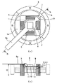
実施の形態2は、実施の形態1のDCブラシレスモータをシールレスポンプの駆動部として使用した場合である。図3(a)は本発明の実施の形態2における4極4スロットのDCブラシレスモータを駆動部とするDCポンプの構成図、図3(b)は(a)のDCポンプのA−A断面図である。
【0029】
実施の形態2のDCポンプについて図3に基づいて説明する。実施の形態2のDCポンプは渦流ポンプもしくは摩擦ポンプであって、羽根車と一体のマグネットロータ4を水封し同時に固定子鉄心1を防水するための隔壁、すなわちキャンとなる分離板(後述する)を有し、マグネットロータ4が直接駆動され軸シールをもたないシールレスポンプである。図1,2と同一符号の構成に関しては同一内容であるから、説明を割愛する。
【0030】
図3(a),(b)において、13はシールレスポンプ内の循環水と電気部(電機子5とFPC基板9の実装部品)とを隔離するための分離板であり、14は固定子鉄心1をポンプ下方から分離板13に圧入して組み立てるとき、突極1aの上面と接触し、圧入位置を決定するコア圧入ストッパー、15はFPC基板9の厚み分だけコア圧入ストッパー14より上部に位置する基板固定用ストッパーである。なお、分離板13はマグネットロータ4を内部に収容したポンプケーシングということができる。
【0031】
実施の形態2のDCポンプは、組み立て時に分離板13の内周面と突極1aの外周面を接触させながら圧入固定する。マグネットロータ4と突極1aの位置が、コア圧入ストッパー14によってモータ性能を最大にする位置に確実に圧入される。このとき同時にポンプ性能も向上する。また、FPC基板9は基板固定用ストッパー15と突極1aに挟まれ簡単且つ確実に固定される。
【0032】
【発明の効果】
以上のように本発明のDCブラシレスモータによれば、モータの薄型化を飛躍的に実現できるとともに、主磁束から磁極位置を検出することで、モータ性能のバラツキをほとんど発生せず、個々のモータのモータ性能を安定化することができる。
【0033】
また、本発明のDCポンプは、DCブラシレスモータのモータ性能の安定性によってポンプ性能の安定化を実現できる。
【図面の簡単な説明】
【図1】(a)本発明におけるフレキシブル基板を設けた4極4スロットのDCブラシレスモータの基本構成図
(b)(a)のDCブラシレスモータのA−A断面図
【図2】(a)本発明の実施の形態1における4極4スロットのDCブラシレスモータの構成図
(b)(a)のDCブラシレスモータのA−A断面図
【図3】(a)本発明の実施の形態2における4極4スロットのDCブラシレスモータを駆動部とするDCポンプの構成図
(b)(a)のDCポンプのA−A断面図
【図4】従来のDCブラシレスモータの構成図
【符号の説明】
1 固定子鉄心
1a 突極
2 ティース
3 巻線コイル
4,106 マグネットロータ
5,108 電機子
6 磁極位置
7,115 磁極位置センサ
8,113 ドライバIC
9 FPC基板
9a FPCリード部
10 補強板
11 屈曲部
12 コイルエンド長
13 分離板
14 コア圧入ストッパー
15 基板固定用ストッパー
107 ロータフレーム
108 電機子
110 巻線
111 リード線
112 基板
114 シールド板
116 コネクタ[0001]
BACKGROUND OF THE INVENTION
The present invention relates to a DC brushless motor that improves the sensitivity of a magnetic pole position sensor, is thin, has a long life, and is highly efficient, and a DC pump including the same.
[0002]
[Prior art]
Since an armature is used by winding a winding around a stator core, there is a need for a physical space, and there is a tendency to increase the size of the mechanism. Recently, there is an increasing demand for downsizing and further thinning.
[0003]
A conventional DC brushless motor for the purpose of reducing the thickness will be described below with reference to FIG. FIG. 4 is a configuration diagram of a conventional DC brushless motor. In FIG. 4, the driver IC 113 is arranged on the
[0004]
With this configuration, pattern wiring from the
[0005]
[Patent Document 1]
Japanese Patent No. 3106582 [0006]
[Problems to be solved by the invention]
However, in the configuration of the conventional DC brushless motor described above, the magnetic
[0007]
In addition, since the conventional DC brushless motor needs to be thinned, the length of the magnet rotor is not sufficient than the length of the stator core, so that the magnetic pole position cannot be reliably detected from the leakage magnetic flux, and stable motor performance is achieved. There was a problem that could not be obtained.
[0008]
Furthermore, the conventional DC pump is not thin and it is difficult to obtain stable pump performance.
[0009]
Accordingly, an object of the present invention is to provide a DC brushless motor that is thin and has a stable motor performance by reliably detecting the magnetic pole position of a magnet rotor.
[0010]
It is another object of the present invention to provide a DC pump that is thin and has a stable output by reliably detecting the magnetic pole position of a magnet rotor.
[0011]
[Means for Solving the Problems]
In order to solve the above problems, the present invention provides a stator core having salient poles at the tips of a plurality of teeth, a magnet rotor that rotates on the outer peripheral side of the salient poles, a winding coil wound around the teeth, and salient poles. DC brushless motor provided with a magnetic pole position sensor for detecting the magnetic pole position of the magnet rotor and a driver IC for controlling a current flowing through the winding coil by an output signal from the magnetic pole position sensor A flexible board on which at least a magnetic pole position sensor and a driver IC are mounted is attached to the stator core at a position where the winding coil is not wound, and the lead portion is externally bent along the motor side shape. and drawn to the ,, flexible substrate is bent from the salient pole side to the magnet rotor which faces the magnetic pole position to the bent portion It characterized that you fitted with the detection surface of the sensor while being opposed to the magnet rotor.
[0012]
Thereby, it is thin and can detect the magnetic pole position of a magnet rotor reliably, and can be made stable motor performance.
[0013]
DETAILED DESCRIPTION OF THE INVENTION
In order to solve the above problems, the invention of claim 1 is directed to a stator core having salient poles at the tips of a plurality of teeth, a magnet rotor rotating on the outer periphery of the salient poles, and a winding wound around the teeth. A magnetic pole position sensor that detects the magnetic pole position of the magnet rotor, and a driver IC that controls the current flowing through the winding coil by an output signal from the magnetic pole position sensor. A DC brushless motor equipped with a flexible substrate on which at least a magnetic pole position sensor and a driver IC are mounted is attached to the stator core at a position where no winding coil is wound, and the lead portion follows the shape of the side surface of the motor. drawn freely to the outside bend Te, and the flexible substrate is bent from the salient pole side to the magnet rotor which faces are bent A DC brushless motor which is characterized that you the detection surface of the magnetic pole position sensor mounted while being opposed to the magnet rotor portion, the lead wires for supplying electricity to the driver IC so use lead portion of the flexible substrate Since it is not necessary and the thin flexible substrate can be bent, it can be attached to the stator core at a position avoiding the winding coil, and the DC brushless motor can be drastically reduced in thickness. It has the effect of improving the degree.
[0014]
Furthermore, when the DC brushless motor is made thinner, the magnetic pole position is not detected by the leakage flux of the magnet rotor, but is detected by the main magnetic flux, so that the detection sensitivity of the magnetic pole position is improved and the motor performance can be stabilized. .
[0015]
The invention of
[0016]
Below, it will be described with reference to FIG. 1 with the basic structure of a DC brushless motor provided with a flexible substrate.
[0017]
(Basic configuration)
FIG. 1A is a basic configuration diagram of a 4- pole 4-slot DC brushless motor , and FIG. 1B is an AA cross-sectional view of the DC brushless motor of FIG. 1 (a) and 1 (b), 1 is a stator core, 1a is a salient pole of the
[0018]
As a material for the stator core 1, a silicon steel plate having a high magnetic permeability and a thickness of about t = 0.2 to 0.5 mm is suitable for reducing iron loss and improving motor efficiency. The stator core 1 is configured by laminating a plurality of steel sheets. The portion of the arm that extends radially from the center of the stator core 1 is a
[0019]
By the way, the
[0020]
The
[0021]
Incidentally, the magnetic
[0022]
The most characteristic part of the DC brushless motor is the shape of the
[0023]
Oite Thus the DC brushless motor of FIG. 1, by laying the
[0024]
(In the form of implementing state 1)
2, will be explained in the form state 1 of the present invention with reference to FIG. Form state first embodiment, in the DC brushless motor of FIG. 1, is intended to improve the sensitivity of the magnetic pole position detecting
[0025]
DC brushless motor in the form state first embodiment, similar to FIG. 1, is bent along the winding
[0026]
[Table 1]
[0027]
By the way, regarding the motor performance defined by the
[0028]
(Form state to the second embodiment)
Shape status second embodiment is a case of using a DC brushless motor in the form state first embodiment as a drive portion of the seal-less pump. 3 (a) is diagram of a DC pump whose drive unit DC brushless motor of four-
[0029]
The DC pump in the form status second embodiment will be described with reference to FIG. DC pump in the form status second embodiment is a vortex pump or friction pump impeller integral with the magnet rotor 4 a water seal and septum for waterproofing the stator core 1 simultaneously, that is, scan separation plate (described later The
[0030]
3 (a) and 3 (b), 13 is a separation plate for isolating the circulating water in the sealless pump and the electrical part (mounted parts of the armature 5 and the FPC board 9), and 14 is a stator. When the iron core 1 is press-fitted into the
[0031]
DC pump in the form status second embodiment is press-fitted and fixed while contacting the inner and outer peripheral surfaces of the
[0032]
【The invention's effect】
According to the DC brushless motor of the present invention as described above, it is possible to dramatically reduce the thickness of the motor, by detecting the magnetic pole position from the main magnetic flux, hardly generate a variation in motor performance, individual The motor performance of the motor can be stabilized.
[0033]
In addition, the DC pump of the present invention can achieve stable pump performance due to the stability of the motor performance of the DC brushless motor.
[Brief description of the drawings]
[1] (a) A-A sectional view of the DC brushless motor of the basic configuration diagram of a DC brushless motor of four-pole four-slot the flexible substrate that put this onset bright provided (b) (a) Figure 2 ] (a) the a-a sectional view of the DC brushless motor configuration diagram of a DC brushless motor of four-
DESCRIPTION OF SYMBOLS 1
9
Claims (2)
Priority Applications (1)
| Application Number | Priority Date | Filing Date | Title |
|---|---|---|---|
| JP2002329436A JP4186593B2 (en) | 2002-11-13 | 2002-11-13 | DC brushless motor and DC pump provided with the same |
Applications Claiming Priority (1)
| Application Number | Priority Date | Filing Date | Title |
|---|---|---|---|
| JP2002329436A JP4186593B2 (en) | 2002-11-13 | 2002-11-13 | DC brushless motor and DC pump provided with the same |
Publications (2)
| Publication Number | Publication Date |
|---|---|
| JP2004166401A JP2004166401A (en) | 2004-06-10 |
| JP4186593B2 true JP4186593B2 (en) | 2008-11-26 |
Family
ID=32807438
Family Applications (1)
| Application Number | Title | Priority Date | Filing Date |
|---|---|---|---|
| JP2002329436A Expired - Fee Related JP4186593B2 (en) | 2002-11-13 | 2002-11-13 | DC brushless motor and DC pump provided with the same |
Country Status (1)
| Country | Link |
|---|---|
| JP (1) | JP4186593B2 (en) |
Cited By (1)
| Publication number | Priority date | Publication date | Assignee | Title |
|---|---|---|---|---|
| CN103973048A (en) * | 2013-02-06 | 2014-08-06 | 株式会社电装 | Rotary motor |
Families Citing this family (26)
| Publication number | Priority date | Publication date | Assignee | Title |
|---|---|---|---|---|
| JP5290608B2 (en) * | 2008-04-01 | 2013-09-18 | アスモ株式会社 | Axial gap motor |
| JP5171953B2 (en) | 2008-06-23 | 2013-03-27 | テルモ株式会社 | Blood pump device |
| EP2372160B1 (en) | 2008-12-08 | 2014-07-30 | Thoratec Corporation | Centrifugal pump device |
| JP5378010B2 (en) | 2009-03-05 | 2013-12-25 | ソラテック コーポレーション | Centrifugal pump device |
| CN102341600B (en) | 2009-03-06 | 2014-12-10 | 胸腔科技有限公司 | Centrifugal pump device |
| DE102009028815A1 (en) * | 2009-08-21 | 2011-02-24 | Robert Bosch Gmbh | Magnetic field sensor and method for producing a magnetic field sensor |
| DE102010005854B4 (en) | 2010-01-26 | 2023-03-02 | Pierburg Gmbh | actuator |
| JP5443197B2 (en) | 2010-02-16 | 2014-03-19 | ソラテック コーポレーション | Centrifugal pump device |
| JP5572832B2 (en) | 2010-03-26 | 2014-08-20 | ソーラテック コーポレイション | Centrifugal blood pump device |
| JP5681403B2 (en) | 2010-07-12 | 2015-03-11 | ソーラテック コーポレイション | Centrifugal pump device |
| JP5577506B2 (en) | 2010-09-14 | 2014-08-27 | ソーラテック コーポレイション | Centrifugal pump device |
| EP2693609B1 (en) * | 2011-03-28 | 2017-05-03 | Thoratec Corporation | Rotation and drive device and centrifugal pump device using same |
| JP6083929B2 (en) | 2012-01-18 | 2017-02-22 | ソーラテック コーポレイション | Centrifugal pump device |
| EP2888483A4 (en) * | 2012-08-24 | 2016-08-17 | Clarcor Engine Mobile Solutions Llc | Integrated brushless direct current motor and lift pump |
| US9371826B2 (en) | 2013-01-24 | 2016-06-21 | Thoratec Corporation | Impeller position compensation using field oriented control |
| US9556873B2 (en) | 2013-02-27 | 2017-01-31 | Tc1 Llc | Startup sequence for centrifugal pump with levitated impeller |
| US9713663B2 (en) | 2013-04-30 | 2017-07-25 | Tc1 Llc | Cardiac pump with speed adapted for ventricle unloading |
| US10052420B2 (en) | 2013-04-30 | 2018-08-21 | Tc1 Llc | Heart beat identification and pump speed synchronization |
| US9623161B2 (en) | 2014-08-26 | 2017-04-18 | Tc1 Llc | Blood pump and method of suction detection |
| EP3256183A4 (en) | 2015-02-11 | 2018-09-19 | Tc1 Llc | Heart beat identification and pump speed synchronization |
| US10166318B2 (en) | 2015-02-12 | 2019-01-01 | Tc1 Llc | System and method for controlling the position of a levitated rotor |
| US10371152B2 (en) | 2015-02-12 | 2019-08-06 | Tc1 Llc | Alternating pump gaps |
| US10245361B2 (en) | 2015-02-13 | 2019-04-02 | Tc1 Llc | Impeller suspension mechanism for heart pump |
| US10117983B2 (en) | 2015-11-16 | 2018-11-06 | Tc1 Llc | Pressure/flow characteristic modification of a centrifugal pump in a ventricular assist device |
| CN109067099B (en) * | 2018-09-25 | 2023-10-03 | 深圳市千代机电设备有限公司 | FPC winding motor and generator |
| WO2023281687A1 (en) * | 2021-07-08 | 2023-01-12 | 三菱電機株式会社 | Position detector and linear conveyance device |
-
2002
- 2002-11-13 JP JP2002329436A patent/JP4186593B2/en not_active Expired - Fee Related
Cited By (2)
| Publication number | Priority date | Publication date | Assignee | Title |
|---|---|---|---|---|
| CN103973048A (en) * | 2013-02-06 | 2014-08-06 | 株式会社电装 | Rotary motor |
| CN103973048B (en) * | 2013-02-06 | 2016-09-07 | 株式会社电装 | Electric rotating machine |
Also Published As
| Publication number | Publication date |
|---|---|
| JP2004166401A (en) | 2004-06-10 |
Similar Documents
| Publication | Publication Date | Title |
|---|---|---|
| JP4186593B2 (en) | DC brushless motor and DC pump provided with the same | |
| JP2699655B2 (en) | Brushless motor and its magnetic sensor installation method | |
| US7304446B2 (en) | Sensorless and brushless DC motor | |
| JP4092128B2 (en) | Electric machine having at least one magnetic field detector | |
| EP0161032A1 (en) | Electric motor | |
| US6013966A (en) | Mini-fan unit especially for use as a fun printed circuit boards | |
| JP4570605B2 (en) | Flat vibration motor | |
| KR101489024B1 (en) | Motor and electronic device using the same | |
| JP2009033786A (en) | Inner rotor brushless motor incorporating bus bar | |
| US6462443B2 (en) | Brushless D.C. motors structure | |
| EP3687045A1 (en) | Electric motor and turbo-compressor | |
| EP1221758B1 (en) | Actuator capable of revolving | |
| US20080143210A1 (en) | Three-phase motor stator | |
| CA3067531C (en) | Electrical machine | |
| JP4479188B2 (en) | DC can pump | |
| CN100499323C (en) | Induction less brush-less DC motor and fan with same | |
| JP4801713B2 (en) | Brushless DC motor | |
| CN1675816A (en) | Four-pole synchronous motor | |
| KR19980070832A (en) | Rotary detector | |
| JPH08256464A (en) | Brushless motor containing stator core integrated with holder | |
| EP2453551A2 (en) | Stator of a fan motor | |
| JP3741091B2 (en) | DC brushless motor and sealless pump using it | |
| WO2009120046A2 (en) | Direct current brushless vibration motor | |
| KR101011444B1 (en) | Bracket of Vibrator motor | |
| JP2021023045A (en) | motor |
Legal Events
| Date | Code | Title | Description |
|---|---|---|---|
| A621 | Written request for application examination |
Free format text: JAPANESE INTERMEDIATE CODE: A621 Effective date: 20050805 |
|
| RD01 | Notification of change of attorney |
Free format text: JAPANESE INTERMEDIATE CODE: A7421 Effective date: 20050913 |
|
| A711 | Notification of change in applicant |
Free format text: JAPANESE INTERMEDIATE CODE: A711 Effective date: 20070316 |
|
| A521 | Written amendment |
Free format text: JAPANESE INTERMEDIATE CODE: A821 Effective date: 20070322 |
|
| RD02 | Notification of acceptance of power of attorney |
Free format text: JAPANESE INTERMEDIATE CODE: A7422 Effective date: 20070322 |
|
| A131 | Notification of reasons for refusal |
Free format text: JAPANESE INTERMEDIATE CODE: A131 Effective date: 20080520 |
|
| A521 | Written amendment |
Free format text: JAPANESE INTERMEDIATE CODE: A523 Effective date: 20080722 |
|
| TRDD | Decision of grant or rejection written | ||
| A01 | Written decision to grant a patent or to grant a registration (utility model) |
Free format text: JAPANESE INTERMEDIATE CODE: A01 Effective date: 20080819 |
|
| A01 | Written decision to grant a patent or to grant a registration (utility model) |
Free format text: JAPANESE INTERMEDIATE CODE: A01 |
|
| A61 | First payment of annual fees (during grant procedure) |
Free format text: JAPANESE INTERMEDIATE CODE: A61 Effective date: 20080901 |
|
| FPAY | Renewal fee payment (event date is renewal date of database) |
Free format text: PAYMENT UNTIL: 20110919 Year of fee payment: 3 |
|
| FPAY | Renewal fee payment (event date is renewal date of database) |
Free format text: PAYMENT UNTIL: 20110919 Year of fee payment: 3 |
|
| S533 | Written request for registration of change of name |
Free format text: JAPANESE INTERMEDIATE CODE: R313533 |
|
| FPAY | Renewal fee payment (event date is renewal date of database) |
Free format text: PAYMENT UNTIL: 20110919 Year of fee payment: 3 |
|
| R350 | Written notification of registration of transfer |
Free format text: JAPANESE INTERMEDIATE CODE: R350 |
|
| FPAY | Renewal fee payment (event date is renewal date of database) |
Free format text: PAYMENT UNTIL: 20110919 Year of fee payment: 3 |
|
| FPAY | Renewal fee payment (event date is renewal date of database) |
Free format text: PAYMENT UNTIL: 20120919 Year of fee payment: 4 |
|
| FPAY | Renewal fee payment (event date is renewal date of database) |
Free format text: PAYMENT UNTIL: 20130919 Year of fee payment: 5 |
|
| LAPS | Cancellation because of no payment of annual fees |