JP4186264B2 - microscope - Google Patents
microscope Download PDFInfo
- Publication number
- JP4186264B2 JP4186264B2 JP24785098A JP24785098A JP4186264B2 JP 4186264 B2 JP4186264 B2 JP 4186264B2 JP 24785098 A JP24785098 A JP 24785098A JP 24785098 A JP24785098 A JP 24785098A JP 4186264 B2 JP4186264 B2 JP 4186264B2
- Authority
- JP
- Japan
- Prior art keywords
- image
- sample
- image signal
- light
- light source
- Prior art date
- Legal status (The legal status is an assumption and is not a legal conclusion. Google has not performed a legal analysis and makes no representation as to the accuracy of the status listed.)
- Expired - Fee Related
Links
Images

Description
【0001】
【発明の属する技術分野】
本発明は、工業顕微鏡等の顕微鏡に関する。
【0002】
【従来の技術】
近年、解像力の高い光学的顕微鏡の需要に伴って、使用波長の短波長化が進んでいる。
従来の顕微鏡の構成を、以下簡単に説明する。光源より発した照明光は、照明レンズを透過して、ハーフミラーに入射する。ハーフミラーに入射した照明光のうちハーフミラーで反射した照明光は、対物レンズを透過してステージ上に載置された試料を照射する。ここで、光軸方向をZ方向とし、Z方向と直交する平面内で互いに直交する2方向をX、Y方向とすると、ステージはステージ駆動系にて、XYZ方向に移動可能となっている。
【0003】
試料で反射した観察光は、対物レンズを透過して、ハーフミラーに入射する。ハーフミラーを透過した観察光は、結像レンズを透過してイメージセンサー上に結像する。イメージセンサーの出力信号は、ビデオ信号処理回路にて画像信号に変換された後、モニターに転送される。これによって、試料の画像がモニター上に表示される。
【0004】
【発明が解決しようとする課題】
上記従来の顕微鏡において、観察者がほとんど静止状態にある試料の画像を長時間眺める場合、試料には照明光が連続的に照射され、試料が変形、変色等の損傷を受けていた。これは、試料に照射される光のエネルギーが徐々に高くなるからである。このような現象は、照明光を微小なスポットに集光させるレーザー走査顕微鏡においては、特に顕著に現れていた。
【0005】
このような試料上の光のエネルギー、すなわち、照明光の照射量は、照度と照射時間との積で求まる。試料が受ける損傷の程度は、この照射量と相関がある。すなわち、照射量が大きいと試料の損傷は大きく、照射量が小さいと試料の損傷は小さくなる。そして、試料の損傷が大きい場合、その試料を再度観察、測定するときの再現性が低下するばかりか、試料が製品であればその品質を低下させることになる。また、試料が微生物等の生物であれば、その生物を死に至らせることもある。
したがって本発明は、試料の変形、変色等の損傷が少ない顕微鏡を提供することを課題とする。
【0006】
【課題を解決するための手段】
本発明は上記課題を解決するためになされたものであり、すなわち、添付図面に付した符号をカッコ内に付記すると、本発明は、光源(1)と、光源(1)より発した照明光を試料(A)に照射する照明光学系(2〜4)と、試料(A)を載置するステージ(5)と、試料(A)より発した観察光を集光する結像光学系(4〜7)と、結像光学系(4〜7)を通過した観察光を検出する検出器(8)と、検出器(8)からの信号を処理する処理装置(9、11)と、処理装置(9、11)からの画像信号に基づいて試料(A)の画像を表示するモニター(10)とを有する顕微鏡において、処理装置(9、11)に入力される画像信号の変化量を検出し、画像信号の変化量が予め定めた値未満のとき、試料(A)上での照明光の照度を画像信号の変化量が検出できる程度まで低減し、照度を低減する直前の画像信号を静止画像としてモニター(10)に送り、画像信号の変化量が予め定めた値以上のとき、照度を試料(A)の画像を表示するのに充分な照度とし、そのときの画像信号を動画像としてモニター(10)に送ることを特徴とする顕微鏡である。
【0007】
以上の構成により、試料面への照明光の照射量は減少して、試料の受ける損傷を減少させることができる。以下、本発明の作用について詳しく説明する。一般に、工業分野、生物分野を問わず顕微鏡においては、画像観察を行うときには観察の精度を維持するため、照度をむやみに下げることはできない。しかし、前述したように、観察者はほとんど静止状態にある試料の画像を長時間眺める場合がある。
【0008】
したがって、このような状態となった瞬間又は予め定められた時間経過した後に、照明光を減光すれば、試料の損傷を防ぐことができる。このとき、モニター上には、減光される直前の画像をフリーズ(固定)して表示する。こうすれば、画像は変化していないので、観察に不都合を生じることはない。また、照度は低減しているので、試料の損傷も防ぐことができる。
そして、画像に変化が生じたとき、モニター上の画面を、速やかに動画像(ライブ画像)に戻す。
【0009】
ここで、画像の変化を検知するために、画像取り込みは常に実行される。すなわち、通常時においては、画像取り込みと、それに対応したモニター上への表示との双方を行なう。減光時においては、画像取り込みは行うが、それに対応したモニター上への表示は行わない。そして、常に、画像取り込みによる画像の変化の有無を判定する。画像に変化がないと判定したときは、減光状態での画像取り込みが継続される。そして、画像に変化があると判定したときは、モニター上へ動画像を表示する。
【0010】
以上のように、モニター上の画像が実質的に変化していないときは、試料への照明は減光されることになる。そして、画像が刻々と変化している場合、例えば、試料上の所望の位置を探している場合や、ピント位置を調整している場合や、生物試料等が生きて動いている場合等、モニター上には常に動画像が表示される。これとは逆に、試料が静止状態になった場合、例えば、位置調整、ピント調整が終了した場合等、減光状態に移行する。
ここで、画像の変化を検知するための装置構成としては、例えば、複数画面の画像データを記憶できるメモリと、それらの情報から画像を比較し変化を判定する電気処理系とを設けることが好ましい。
【0011】
【発明の実施の形態】
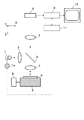
本発明の実施の形態を図面によって説明する。図1は、本発明による顕微鏡の第1実施例である。
光源1より発した照明光は、照明レンズ2を透過して、ハーフミラー3に入射する。ここで、光源1の出力は、光源制御装置1aによって制御されている。ハーフミラー3に入射した照明光のうちハーフミラー3で反射した照明光は、対物レンズ4を透過してステージ5上に載置された試料Aを照射する。ここで、ステージ5はステージ駆動系6にて、XYZ方向に移動可能となっている。
試料Aで反射した観察光は、対物レンズ4を透過して、ハーフミラー3に入射する。ハーフミラー3を透過した観察光は、結像レンズ7を透過してイメージセンサー8上に結像する。そして、イメージセンサー8の出力信号は、ビデオ信号処理系9にて画像信号に変換される。
【0012】
ビデオ信号処理系9で変換された画像信号は、画像判定回路11に転送される。画像判定回路11では、転送された画像信号に基づいて画像の変化の有無を判定する。ここで、画像判定回路11は、複数の画像データを記憶できるメモリと、それらのデータから画像の変化の有無を判定する判定処理系とで構成される。ここで、判定処理系としては、例えば、以下のようなアルゴリズムとなる。まず、メモリ内に記憶された2つの画像データについて、ピクセル毎に輝度信号の差をとる。そして、その自乗和が予め定めた値以上となる場合に画像変化が有りと判定し、自乗和が予め定めた値未満となる場合に画像変化がなしと判定する。なお、画像変化に対する判定アルゴリズムは、これ以外にも色々なアルゴリズムが可能である。
【0013】
画像判定回路11にて、予め定められた時間を超えて画像が変化していないと判断された場合、光源1の出力を、例えば通常出力の半分に低下させる。そして、モニター10上には、光源1の出力が低下する直前の画像が静止画として表示される。このとき、ビデオ信号処理系9における画像取り込みは、モニター10上への表示を行わずに続行され、この間も画像判定回路11によって、常に画像の変化の有無が判定されている。ここで、減光された照明光による画像信号は、画像判定回路11にて画像変化を判定するのに充分な程度のものである。
そして、画像変化が有ると判定した場合は、直ちに光源1の出力を通常出力に戻して、ビデオ信号処理系9で変換された画像信号を、画像判定回路11に転送すると共に、モニター10にも転送する。このとき、試料Aは通常出力で照明され、モニター10上には試料Aの動画像が連続的に表示されることになる。
【0014】
以上のように、本第1実施例では、試料Aに不必要な照明光を照射することを避けて、試料Aの損傷を効果的に低減することができる。
なお、本第1実施例では、光源1の出力を低下させることにより、試料Aに至る照明光の減光をおこなったが、その代わりに、光源1からステージ5までの照明光の光路中に減光部材、例えば、透過率の低い平行平板を挿入し、この減光部材の開閉動作によって照明光の減光を達成しても良い。この他、減光方法としては、例えば、偏光を利用して偏光板や波長板を回転させる方法や、液晶の波長板を電気的に変調して調光する方法等がある。
【0015】
次に、図2にて、本発明による顕微鏡の第2実施例を示す。図2は、共焦点型のレーザー走査顕微鏡である。
レーザー光源21より発した照明光は、照明レンズ2を透過して、ハーフミラー3に入射する。ハーフミラー3で反射した照明光は、2次元光ビーム走査手段24、対物レンズ4を通過してステージ5上の試料Aの表面に微小なレーザースポットを形成する。
【0016】
試料Aで反射した観察光は、対物レンズ4、2次元光ビーム走査手段24を通過して、ハーフミラー3に入射する。ハーフミラー3を透過した観察光は、集光レンズ28を透過して、ピンホール29上に再びスポットを形成する。ピンホール29を通過した観察光は、検出器30に入射する。検出器30に入射した観察光は光電変換されて、2次元光ビーム走査手段24からの制御信号と共に、信号処理系31にて画像信号に変換される。
本第2実施例においても、前記第1実施例と同様に、信号処理系31で変換された画像信号は、画像判定回路11に転送される。画像判定回路11では、転送された画像信号に基づいて画像の変化の有無を判定する。
【0017】
画像判定回路11にて、予め定められた時間を超えて画像が変化していないと判断された場合、減光部材35は照明光の光路内に移動する。そして、モニター10には、減光部材35が照明光を減光する直前の画像が静止画として表示される。このとき、信号処理系31における画像取り込みは、モニター10への表示を行わずに続行され、この間も画像判定回路11によって、常に画像の変化の有無が判定されている。ここで、減光された照明光による画像信号は、画像判定回路11にて画像変化を判定するのに充分な程度のものである。
そして、画像変化が有ると判定した場合は、直ちに減光部材35を光路外へ移動し、信号処理系31で変換された画像信号を、画像判定回路11に転送すると共に、モニター10にも転送する。このとき、試料Aは通常出力で照明され、モニター10上には試料Aの動画像が連続的に表示されることになる。
【0018】
以上のように、本第2実施例においても、前記第1実施例と同様に、試料Aに不必要な照明光を照射することを避けて、試料Aの損傷を効果的に低減することができる。また、本第2実施例においては、レーザー光源21を用いているため、その波長領域が短い。波長が可視域より短い場合、例えば紫外域〜軟X線領域の短波長領域である場合、不必要な照明光の照射を避けて、試料の損傷を低減することが特に重要となる。
なお、本実施例では、反射照明型の顕微鏡について説明したが、本発明は、透過照明型の顕微鏡にも適用できる。
また、本実施例における顕微鏡は、モニター10上で試料Aの計測を行うことで測定装置として用いることもできる。
【0019】
【発明の効果】
以上のように本発明では、画像の変化がないときに試料が受ける照明光の照度を低減できるので、試料の損傷の少ない顕微鏡を提供できる。
【図面の簡単な説明】
【図1】本発明の第1実施例による顕微鏡を示す概略図である。
【図2】本発明の第2実施例による顕微鏡を示す概略図である。
【符号の説明】
1…光源 1a…光源制御装置
2…照明レンズ
3…ハーフミラー 4…対物レンズ
5…ステージ 6…ステージ駆動系
7…結像レンズ 8…イメージセンサー
9…ビデオ信号処理系 10…モニター
11…画像判定回路
21…レーザー光源 24…2次元光ビーム走査手段
28…集光レンズ 29…ピンホール
30…検出器 31…信号処理系
35…減光部材 A…試料[0001]
BACKGROUND OF THE INVENTION
The present invention relates to a microscope such as an industrial microscope.
[0002]
[Prior art]
In recent years, with the demand for optical microscopes with high resolving power, the wavelength used has been shortened.
The configuration of a conventional microscope will be briefly described below. The illumination light emitted from the light source passes through the illumination lens and enters the half mirror. Of the illumination light incident on the half mirror, illumination light reflected by the half mirror passes through the objective lens and irradiates the sample placed on the stage. Here, assuming that the optical axis direction is the Z direction and two directions orthogonal to each other in a plane orthogonal to the Z direction are the X and Y directions, the stage can be moved in the XYZ directions by the stage drive system.
[0003]
The observation light reflected by the sample passes through the objective lens and enters the half mirror. The observation light transmitted through the half mirror passes through the imaging lens and forms an image on the image sensor. The output signal of the image sensor is converted into an image signal by the video signal processing circuit and then transferred to the monitor. As a result, an image of the sample is displayed on the monitor.
[0004]
[Problems to be solved by the invention]
In the conventional microscope, when an observer views an image of a sample that is almost stationary for a long time, the sample is continuously irradiated with illumination light, and the sample is damaged such as deformation or discoloration. This is because the energy of light applied to the sample gradually increases. Such a phenomenon is particularly prominent in a laser scanning microscope that condenses illumination light into a minute spot.
[0005]
The energy of light on the sample, that is, the irradiation amount of the illumination light, is obtained by the product of the illuminance and the irradiation time. The degree of damage to the sample correlates with this dose. That is, the sample damage is large when the irradiation amount is large, and the sample damage is small when the irradiation amount is small. If the sample is severely damaged, not only the reproducibility when the sample is observed and measured again, but also the quality of the sample is degraded. Further, if the sample is an organism such as a microorganism, the organism may be killed.
Therefore, an object of the present invention is to provide a microscope with little damage such as deformation and discoloration of a sample.
[0006]
[Means for Solving the Problems]
The present invention has been made to solve the above-described problems. That is, when the reference numerals in the attached drawings are added in parentheses, the present invention provides a light source (1) and illumination light emitted from the light source (1). Optical system (2-4) that irradiates the sample (A), a stage (5) on which the sample (A) is placed, and an imaging optical system that collects the observation light emitted from the sample (A) ( 4-7), a detector (8) for detecting observation light that has passed through the imaging optical system (4-7), a processing device (9, 11) for processing signals from the detector (8), In a microscope having a monitor (10) that displays an image of a sample (A) based on an image signal from the processing device (9, 11), a change amount of the image signal input to the processing device (9, 11) is determined. When the amount of change in the detected image signal is less than a predetermined value, the illuminance of the illumination light on the sample (A) The image signal immediately before reducing the illuminance is sent to the monitor (10) as a still image, and when the change amount of the image signal is equal to or greater than a predetermined value, the illuminance is reduced to the sample (A). The microscope is characterized in that the illuminance is sufficient to display the image and the image signal at that time is sent as a moving image to the monitor (10).
[0007]
With the above configuration, the amount of illumination light applied to the sample surface can be reduced, and damage to the sample can be reduced. Hereinafter, the operation of the present invention will be described in detail. In general, in a microscope regardless of the industrial field or the biological field, the illuminance cannot be reduced unnecessarily in order to maintain observation accuracy when performing image observation. However, as described above, the observer may look at the image of the sample that is almost stationary for a long time.
[0008]
Therefore, if the illumination light is dimmed at the moment when such a state is reached or after a predetermined time has elapsed, damage to the sample can be prevented. At this time, the image immediately before being dimmed is displayed frozen on the monitor. In this way, since the image has not changed, there is no inconvenience in observation. In addition, since the illuminance is reduced, the sample can be prevented from being damaged.
When a change occurs in the image, the screen on the monitor is quickly returned to the moving image (live image).
[0009]
Here, in order to detect a change in the image, image capture is always executed. That is, during normal times, both image capture and display on the monitor corresponding to the image capture are performed. At the time of dimming, the image is captured, but the corresponding display on the monitor is not performed. Then, it is always determined whether or not there is a change in the image due to image capture. When it is determined that there is no change in the image, the image capture in the dimmed state is continued. When it is determined that there is a change in the image, the moving image is displayed on the monitor.
[0010]
As described above, when the image on the monitor is not substantially changed, the illumination on the sample is dimmed. And when the image is changing every moment, for example, when searching for a desired position on the sample, when adjusting the focus position, or when the biological sample etc. is alive and moving A moving image is always displayed on the top. On the other hand, when the sample is in a stationary state, for example, when the position adjustment and the focus adjustment are completed, the light transition is made.
Here, as an apparatus configuration for detecting a change in an image, for example, it is preferable to provide a memory that can store image data of a plurality of screens and an electric processing system that compares the image based on the information and determines the change. .
[0011]
DETAILED DESCRIPTION OF THE INVENTION
Embodiments of the present invention will be described with reference to the drawings. FIG. 1 is a first embodiment of a microscope according to the present invention.
The illumination light emitted from the
The observation light reflected by the sample A passes through the
[0012]
The image signal converted by the video
[0013]
When the
If it is determined that there is an image change, the output of the
[0014]
As described above, in the first embodiment, it is possible to effectively reduce the damage to the sample A by avoiding unnecessary irradiation of the sample A with the illumination light.
In the first embodiment, the illumination light reaching the sample A is reduced by reducing the output of the
[0015]
Next, FIG. 2 shows a second embodiment of the microscope according to the present invention. FIG. 2 is a confocal laser scanning microscope.
The illumination light emitted from the
[0016]
The observation light reflected by the sample A passes through the
Also in the second embodiment, as in the first embodiment, the image signal converted by the
[0017]
When the
If it is determined that there is an image change, the dimming
[0018]
As described above, also in the second embodiment, similarly to the first embodiment, it is possible to avoid irradiating the sample A with unnecessary illumination light and effectively reduce the damage to the sample A. it can. In the second embodiment, since the
In the present embodiment, the reflection illumination type microscope has been described, but the present invention can also be applied to a transmission illumination type microscope.
In addition, the microscope in the present embodiment can be used as a measuring device by measuring the sample A on the
[0019]
【The invention's effect】
As described above, according to the present invention, since the illuminance of illumination light received by the sample when there is no change in the image can be reduced, a microscope with little sample damage can be provided.
[Brief description of the drawings]
FIG. 1 is a schematic view showing a microscope according to a first embodiment of the present invention.
FIG. 2 is a schematic view showing a microscope according to a second embodiment of the present invention.
[Explanation of symbols]
DESCRIPTION OF
Claims (5)
前記光源より発した照明光を試料に照射する照明光学系と、
前記試料を載置するステージと、
前記試料より発した観察光を集光する結像光学系と、
前記結像光学系を通過した前記観察光を検出する検出器と、
前記検出器からの信号を処理する処理装置と、
前記処理装置からの画像信号に基づいて前記試料の画像を表示するモニターと、
前記処理装置に入力される画像信号の変化量を検出し、前記画像信号の変化量が予め定めた値未満のとき、前記試料上での前記照明光の照度を前記画像信号の変化量が検出できる程度まで低減し、前記照度を低減する直前の画像信号を静止画像として前記モニターに送り、前記画像信号の変化量が予め定めた値以上のとき、前記照度を前記試料の画像を表示するのに充分な照度とし、そのときの画像信号を動画像として前記モニターに送る制御手段とを備えることを特徴とする顕微鏡。A light source;
An illuminating optical system for irradiating the illumination light emitted from the light source to the sample,
A stage on which the sample is placed;
An imaging optical system for collecting observation light emitted from the sample;
A detector that detects the observation light that has passed through the imaging optical system;
A processor for processing signals from the detector,
A monitor for displaying an image of the sample on the basis of the image signal from the processing unit,
It said processing unit detects the change amount of the image signal input to, when said amount of change image signal is smaller than a predetermined value, the amount of change in the image signal illuminance of the illumination light on the sample is detected The image signal immediately before reducing the illuminance is sent to the monitor as a still image, and when the change amount of the image signal is a predetermined value or more, the illuminance is displayed as an image of the sample. And a control means for sending the image signal at that time to the monitor as a moving image.
前記光源は、波長が可視域より短いコヒーレント光源であり、
前記照明光学系は、前記照明光を前記試料の面方向に2次元的に走査する走査手段を有し、
前記処理装置は、前記検出器からの信号と前記走査手段からの信号とを処理することを特徴とする請求項1〜4のいずれか1項記載の顕微鏡。 The microscope is a confocal laser scanning microscope,
The light source is a coherent light source having a wavelength shorter than the visible range ,
The illumination optical system has scanning means for two-dimensionally scanning the illumination light in the surface direction of the sample,
The microscope according to any one of claims 1 to 4, wherein the processing device processes a signal from the detector and a signal from the scanning unit.
Priority Applications (3)
| Application Number | Priority Date | Filing Date | Title |
|---|---|---|---|
| JP24785098A JP4186264B2 (en) | 1998-08-18 | 1998-08-18 | microscope |
| US09/375,385 US6400502B1 (en) | 1998-08-18 | 1999-08-17 | Microscope |
| US09/794,080 US6583928B2 (en) | 1998-08-18 | 2001-02-28 | Microscope |
Applications Claiming Priority (1)
| Application Number | Priority Date | Filing Date | Title |
|---|---|---|---|
| JP24785098A JP4186264B2 (en) | 1998-08-18 | 1998-08-18 | microscope |
Publications (3)
| Publication Number | Publication Date |
|---|---|
| JP2000066109A JP2000066109A (en) | 2000-03-03 |
| JP2000066109A5 JP2000066109A5 (en) | 2005-10-27 |
| JP4186264B2 true JP4186264B2 (en) | 2008-11-26 |
Family
ID=17169593
Family Applications (1)
| Application Number | Title | Priority Date | Filing Date |
|---|---|---|---|
| JP24785098A Expired - Fee Related JP4186264B2 (en) | 1998-08-18 | 1998-08-18 | microscope |
Country Status (1)
| Country | Link |
|---|---|
| JP (1) | JP4186264B2 (en) |
Families Citing this family (4)
| Publication number | Priority date | Publication date | Assignee | Title |
|---|---|---|---|---|
| JP4281033B2 (en) | 1999-10-12 | 2009-06-17 | 株式会社ニコン | Laser microscope and confocal laser scanning microscope |
| NL1023440C2 (en) * | 2003-05-16 | 2004-11-17 | Univ Amsterdam | Method and device for forming an image of an object. |
| US8264768B2 (en) | 2007-06-07 | 2012-09-11 | Olympus Corporation | Microscope system |
| JP5230988B2 (en) | 2007-09-28 | 2013-07-10 | オリンパス株式会社 | Microscope camera |
Family Cites Families (2)
| Publication number | Priority date | Publication date | Assignee | Title |
|---|---|---|---|---|
| JPH0633114U (en) * | 1992-09-29 | 1994-04-28 | 株式会社キーエンス | Light intensity adjustment device for microscope |
| JP3537205B2 (en) * | 1995-02-02 | 2004-06-14 | オリンパス株式会社 | Microscope equipment |
-
1998
- 1998-08-18 JP JP24785098A patent/JP4186264B2/en not_active Expired - Fee Related
Also Published As
| Publication number | Publication date |
|---|---|
| JP2000066109A (en) | 2000-03-03 |
Similar Documents
| Publication | Publication Date | Title |
|---|---|---|
| JP3731073B2 (en) | Microscope equipment | |
| US5353073A (en) | Three-dimensional shape measurement system | |
| US6400502B1 (en) | Microscope | |
| US7915575B2 (en) | Laser scanning microscope having an IR partial transmission filter for realizing oblique illumination | |
| JP2000275582A (en) | Depth-of-field enlarging system | |
| Kino | Intermediate optics in Nipkow disk microscopes | |
| US20090010504A1 (en) | Confocal Microscope Apparatus | |
| JPH0738046B2 (en) | Surface inspection device for semi-transparent sheet-like samples with internal structure | |
| JP4186263B2 (en) | microscope | |
| JP2003029153A (en) | Laser microscope | |
| JP4186264B2 (en) | microscope | |
| JP2001235686A (en) | Endoscope device | |
| JP3568286B2 (en) | Confocal scanning optical microscope and measuring method using this microscope | |
| JP2000066110A (en) | Microscope | |
| JP3814869B2 (en) | Confocal laser scanning microscope | |
| JP3458002B2 (en) | Confocal microscope | |
| MacAulay et al. | Use of digital micromirror devices in quantitative microscopy | |
| JPH1195119A (en) | Scanning microscope | |
| Dlugan et al. | Improvements to quantitative microscopy through the use of digital micromirror devices | |
| JPH09211333A (en) | Scanning type sample measurement device | |
| JP2005148584A (en) | Confocal laser microscope | |
| JP2004102032A (en) | Scanning type confocal microscope system | |
| JP2000066108A (en) | Microscope | |
| JP3075308B2 (en) | Microscope photography equipment | |
| JPH10288741A (en) | Microscope |
Legal Events
| Date | Code | Title | Description |
|---|---|---|---|
| A621 | Written request for application examination |
Free format text: JAPANESE INTERMEDIATE CODE: A621 Effective date: 20050704 |
|
| A521 | Written amendment |
Free format text: JAPANESE INTERMEDIATE CODE: A523 Effective date: 20050711 |
|
| RD02 | Notification of acceptance of power of attorney |
Free format text: JAPANESE INTERMEDIATE CODE: A7422 Effective date: 20050711 |
|
| TRDD | Decision of grant or rejection written | ||
| A01 | Written decision to grant a patent or to grant a registration (utility model) |
Free format text: JAPANESE INTERMEDIATE CODE: A01 Effective date: 20080819 |
|
| A01 | Written decision to grant a patent or to grant a registration (utility model) |
Free format text: JAPANESE INTERMEDIATE CODE: A01 |
|
| A61 | First payment of annual fees (during grant procedure) |
Free format text: JAPANESE INTERMEDIATE CODE: A61 Effective date: 20080901 |
|
| R150 | Certificate of patent or registration of utility model |
Free format text: JAPANESE INTERMEDIATE CODE: R150 |
|
| FPAY | Renewal fee payment (event date is renewal date of database) |
Free format text: PAYMENT UNTIL: 20110919 Year of fee payment: 3 |
|
| FPAY | Renewal fee payment (event date is renewal date of database) |
Free format text: PAYMENT UNTIL: 20110919 Year of fee payment: 3 |
|
| FPAY | Renewal fee payment (event date is renewal date of database) |
Free format text: PAYMENT UNTIL: 20140919 Year of fee payment: 6 |
|
| S531 | Written request for registration of change of domicile |
Free format text: JAPANESE INTERMEDIATE CODE: R313531 |
|
| FPAY | Renewal fee payment (event date is renewal date of database) |
Free format text: PAYMENT UNTIL: 20140919 Year of fee payment: 6 |
|
| R350 | Written notification of registration of transfer |
Free format text: JAPANESE INTERMEDIATE CODE: R350 |
|
| FPAY | Renewal fee payment (event date is renewal date of database) |
Free format text: PAYMENT UNTIL: 20140919 Year of fee payment: 6 |
|
| R250 | Receipt of annual fees |
Free format text: JAPANESE INTERMEDIATE CODE: R250 |
|
| R250 | Receipt of annual fees |
Free format text: JAPANESE INTERMEDIATE CODE: R250 |
|
| R250 | Receipt of annual fees |
Free format text: JAPANESE INTERMEDIATE CODE: R250 |
|
| LAPS | Cancellation because of no payment of annual fees |