JP4186242B2 - Image signal processing apparatus and image signal processing method - Google Patents
Image signal processing apparatus and image signal processing method Download PDFInfo
- Publication number
- JP4186242B2 JP4186242B2 JP36150097A JP36150097A JP4186242B2 JP 4186242 B2 JP4186242 B2 JP 4186242B2 JP 36150097 A JP36150097 A JP 36150097A JP 36150097 A JP36150097 A JP 36150097A JP 4186242 B2 JP4186242 B2 JP 4186242B2
- Authority
- JP
- Japan
- Prior art keywords
- image
- small block
- input image
- filter
- block
- Prior art date
- Legal status (The legal status is an assumption and is not a legal conclusion. Google has not performed a legal analysis and makes no representation as to the accuracy of the status listed.)
- Expired - Fee Related
Links
Images


Classifications
-
- H—ELECTRICITY
- H04—ELECTRIC COMMUNICATION TECHNIQUE
- H04N—PICTORIAL COMMUNICATION, e.g. TELEVISION
- H04N9/00—Details of colour television systems
- H04N9/79—Processing of colour television signals in connection with recording
- H04N9/80—Transformation of the television signal for recording, e.g. modulation, frequency changing; Inverse transformation for playback
- H04N9/804—Transformation of the television signal for recording, e.g. modulation, frequency changing; Inverse transformation for playback involving pulse code modulation of the colour picture signal components
- H04N9/8042—Transformation of the television signal for recording, e.g. modulation, frequency changing; Inverse transformation for playback involving pulse code modulation of the colour picture signal components involving data reduction
-
- H—ELECTRICITY
- H04—ELECTRIC COMMUNICATION TECHNIQUE
- H04N—PICTORIAL COMMUNICATION, e.g. TELEVISION
- H04N19/00—Methods or arrangements for coding, decoding, compressing or decompressing digital video signals
- H04N19/50—Methods or arrangements for coding, decoding, compressing or decompressing digital video signals using predictive coding
- H04N19/503—Methods or arrangements for coding, decoding, compressing or decompressing digital video signals using predictive coding involving temporal prediction
- H04N19/51—Motion estimation or motion compensation
- H04N19/527—Global motion vector estimation
-
- H—ELECTRICITY
- H04—ELECTRIC COMMUNICATION TECHNIQUE
- H04N—PICTORIAL COMMUNICATION, e.g. TELEVISION
- H04N19/00—Methods or arrangements for coding, decoding, compressing or decompressing digital video signals
- H04N19/60—Methods or arrangements for coding, decoding, compressing or decompressing digital video signals using transform coding
- H04N19/61—Methods or arrangements for coding, decoding, compressing or decompressing digital video signals using transform coding in combination with predictive coding
-
- H—ELECTRICITY
- H04—ELECTRIC COMMUNICATION TECHNIQUE
- H04N—PICTORIAL COMMUNICATION, e.g. TELEVISION
- H04N19/00—Methods or arrangements for coding, decoding, compressing or decompressing digital video signals
- H04N19/80—Details of filtering operations specially adapted for video compression, e.g. for pixel interpolation
- H04N19/82—Details of filtering operations specially adapted for video compression, e.g. for pixel interpolation involving filtering within a prediction loop
-
- H—ELECTRICITY
- H04—ELECTRIC COMMUNICATION TECHNIQUE
- H04N—PICTORIAL COMMUNICATION, e.g. TELEVISION
- H04N19/00—Methods or arrangements for coding, decoding, compressing or decompressing digital video signals
- H04N19/85—Methods or arrangements for coding, decoding, compressing or decompressing digital video signals using pre-processing or post-processing specially adapted for video compression
- H04N19/86—Methods or arrangements for coding, decoding, compressing or decompressing digital video signals using pre-processing or post-processing specially adapted for video compression involving reduction of coding artifacts, e.g. of blockiness
-
- H—ELECTRICITY
- H04—ELECTRIC COMMUNICATION TECHNIQUE
- H04N—PICTORIAL COMMUNICATION, e.g. TELEVISION
- H04N5/00—Details of television systems
- H04N5/76—Television signal recording
- H04N5/84—Television signal recording using optical recording
- H04N5/85—Television signal recording using optical recording on discs or drums
Description
【0001】
【発明の属する技術分野】
本発明は、動画像信号及び静止画像信号を、例えば光ディスクや磁気テープ等の記録媒体に記録再生したり、テレビ会議システム、テレビ電話システムや放送機器等、動画像信号及び静止画像信号を転送路を介して送信側から受信側に伝送する場合等に用いて好適な画像信号処理装置及び画像信号処理方法に関する。
【0002】
【従来の技術】
従来、静止画データや動画像データ等を効率よく圧縮符号化するための符号化方式として、ブロックDCT(離散コサイン変換)符号化等のブロック符号化が知られている。
【0003】
このように符号化による画像データ等の圧縮/伸張の際には、リンギングノイズ(モスキートノイズ)やブロック歪が発生することがあり、圧縮率が高くなるほどノイズを発生させ易い。また、このノイズは、入力される画像データが複雑であるほど生じさせ易い。この結果、圧縮/伸張された画像データが示す画像には、ノイズによる劣化が生ずるという不都合が生ずる。
【0004】
このような圧縮/伸張の際に生ずる画像データのノイズによる画像劣化を少なくするために、従来では、例えばLPF(ローパスフィルタ)等のプリフィルタを使用し、符号化を行う前の入力画像を示す画像データに対してフィルタリング処理を施すことが多い。
【0005】
図44は、上記プリフィルタを使用する従来の動画像信号の符号化装置の一例である。
【0006】
図44に示す符号化装置では、端子201から入力されるディジタル動画像信号は、プリフィルタ回路202でフィルタリング処理される。このフィルタリング処理がなされた処理画像信号S211は、符号化回路205へ入力される。
【0007】
符号化回路205は、動き補償フレーム間予測とDCT等の変換符号化を組み合わせたハイブリッド符号化方法を用いてディジタル動画像信号に符号化処理を施すものである。すなわち、符号化回路205は、入力信号S211に対してフレーム間/内適応予測を施し、演算器206にて予測誤差信号にDCTを施す。そして、量子化器208にて、上記計算されたDCT係数を量子化し、符号化出力信号S215を端子220から出力する。ここで、量子化器208は、出力信号S215のビットレートが一定となるような量子化ステップサイズを決定している。
【0008】
一方、出力信号S215は、逆量子化器209にて逆量子化された後、逆DCT器210にて逆DCT処理され予測誤差信号が復元され、さらに演算器211にて当該予測誤差信号に予測画像信号が加算されて局部復号がなされる。この加算により得られた復号画像信号S213がフレームメモリ212へ記憶される。
【0009】
一般に、符号化回路205では、入力動画像の絵柄が複雑だったり、動きが大きい程、フレーム間差分信号S212が大きくなる。このとき、符号化の発生情報量を定められたビットレートに抑えるために、量子化器208にて粗い量子化を用いると、視覚上目立つブロック歪が発生し、主観画質が劣化する。
【0010】
そこで、図44に示した符号化装置では、入力画像のフレーム間差分信号の大きさがフレーム間予測符号化の発生符号量に影響を与えることを考慮して、入力画像のフレーム間差分信号の大きさに応じて、入力画像に対するプリフィルタのローパス通過帯域を制限している。これにより、予測誤差信号のエネルギが減衰され、粗い量子化を防ぐことができるので、主観画質を向上させることができる。
【0011】
つぎに、この符号化装置における可変プリフィルタ制御方法について説明する。
【0012】
演算器204では、端子201から入力される画像信号S210とフレームメモリ212から入力される画像信号S214とのフレーム間差分rが計算される。ここで、画像信号S214は、入力画像信号S210のフレーム間予測で参照される信号である。フレーム間差分rは、プリフィルタ制御部203へ入力され、このプリフィルタ処理部203では、上記フレーム間差分rの大きさに応じてプリフィルタのローパス通過帯域を制御するためのパラメータとしてプリフィルタ係数kを生成出力する。当該プリフィルタ202は、図45の2次元ローパスフィルタ特性を持ち、ローパス通過帯域は、上記プリフィルタ係数kに対して単調増加である。図46には、フレーム間差分rとプリフィルタ係数kの関係を示す。このように、プリフィルタ制御器203では、上記関係により、入力画像のフレーム間差分信号の大きさに応じてプリフィルタのローパス特性を制御している。
【0013】
また、復号後に、モスキートノイズ及びブロック歪を低減する手法としては、画像の局所統計量と符号化情報をもとにブロックレベルのマクロな特性と画素レベルのミクロな特性から画素単位の雑音量の予測を行い、適応フィルタリングにより雑音の成分を除去する方式を採用したものがある。
【0014】
また、ブロック歪又はモスキートノイズを低減する手法としては、上述の手法の他に、画像信号を復号して出力するとき、復号後の画像信号にフィルタリングを行うポストフィルタ処理を行う手法がある。
【0015】
【発明が解決しようとする課題】
ところで、上述した符号化前のプリフィルタ処理により、モスキートノイズを抑制できるものの、特に動きが激しい絵柄の画像においては、ブロック歪を効果的に除去できないばかりか、プリフィルタ処理により高周波成分が低減され、プリフィルタ処理を施した画像について復号処理を行うと、ブロック歪のみが目につくといった問題点がある。
【0016】
また一方で、後者の復号処理後のポストフィルタ処理は、符号化側での処理を行わないため符号化後の符号化効率に変化はなく、特に動きが激しく、動きの予測が困難な入力画像に対して、全体に渡って量子化が粗くなることに改善効果が得られないという問題点がある。
【0017】
すなわち、従来の画像符号化/復号装置では、符号化前のプリフィルタ処理と復号後のポストフィルタ処理が独立に行われており、効果的なノイズ除去を行うことができないという欠点がある。
【0018】
そこで、本発明は、上述したような実情に鑑みて提案されたものであり、入力された動画像または静止画像を符号化または復号するときに生ずるモスキートノイズを抑制するとともにブロック歪を抑制する画像信号処理装置及び画像信号処理方法を提供することを目的とする。
【0019】
【課題を解決するための手段】
本発明は、入力画像に圧縮符号化処理及び復号処理を施す画像信号処理装置において、入力画像にフィルタリング処理を施すフィルタ手段と、上記フィルタ手段が行うフィルタリング処理のフィルタレベルを検出するフィルタレベル検出手段と、上記フィルタ手段でフィルタリング処理が施された画像にブロック符号化処理を施す圧縮符号化手段と、上記圧縮符号化手段で圧縮符号化された画像に復号処理を施す復号手段と、上記フィルタレベルに応じて上記復号手段で復号処理が施された画像のブロック歪を少なくとも低減する処理を行うノイズ低減手段とを備え、上記フィルタレベル検出手段は、検出したフィルタレベルを上記ノイズ低減手段に供給し、上記フィルタレベルが強いときには高い周波数帯域の帰還量を大きくして、上記ノイズ低減手段により高い周波数帯域の小振幅のノイズを低減することを特徴とする。
【0020】
このような画像信号処理装置によれば、入力された画像に対して圧縮符号化手段を通過させる前にフィルタ手段でフィルタリング処理を行い、復号手段で復号された画像のブロック歪をノイズ低減手段で低減する処理を行う。
【0021】
また、本発明は、入力画像に圧縮符号化処理及び復号処理を施す画像信号処理方法において、入力画像にフィルタリング処理を施し、上記フィルタリング処理におけるフィルタレベルを検出し、上記フィルタリング処理が施された画像にブロック符号化処理を施し、上記ブロック符号化処理が施された画像に復号処理を施し、上記復号処理が施された画像のブロック歪を少なくとも低減するノイズ低減処理を行い、上記ノイズ低減処理では、検出した上記フィルタリング処理におけるフィルタレベルが強いときには高い周波数帯域の帰還量を大きくして、高い周波数帯域の小振幅のノイズを低減するノイズ低減処理を行うことを特徴とする。
【0022】
このような画像信号方法によれば、入力された画像に対して圧縮符号化を行う前にフィルタリング処理を行い、復号された後に画像のブロック歪を低減する処理を行う。
【0023】
【発明の実施の形態】
以下、本発明の実施の形態について図面を参照しながら説明する。
【0024】
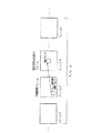
本発明に係る画像信号処理装置及び画像信号処理方法は、図1に示す光ディスク記録再生装置1に適用される。
【0025】
この図1に示す光ディスク記録再生装置1の記録系は、入力端子2から画像信号が入力されるA/D変換回路3と、A/D変換回路3から画像データが入力されるNTSC(National Television System Committee)デコーダ4と、NTSCデコーダ4から画像データが入力されるMPEG(Moving Picture Experts Group)エンコーダ5と、MPEGエンコーダ5から画像データが入力されるECCエンコーダ6と、ECC(Error Correction Codes)エンコーダ6から画像データが入力される8−14変調回路7と、8−14変調回路7から画像データが入力されるRFアンプ8とで構成されている。
【0026】
A/D変換回路3は、入力端子2からのNTSC方式の画像信号が入力されて、A/D変換処理を施す。このA/D変換回路3は、A/D変換処理を施すことで、アナログ方式の画像信号をディジタル方式の画像データとする。そして、このA/D変換回路3は、画像データをNTSCデコーダ4に出力する。
【0027】
NTSCデコーダ4には、A/D変換回路3からのNTSC方式の画像データが入力される。このNTSCデコーダ4は、NTSC方式のコンポジット信号にデコード処理を施す。このNTSCデコーダ4は、デコード処理を施すことで、画像データをベースバンド信号に変換する。そして、このNTSCデコーダ4は、画像データをMPEGエンコーダ5に出力する。
【0028】
MPEGエンコーダ5は、NTSCデコーダ4からの画像データにブロックDCT(Discrete Cosine Transform:離散コサイン変換)符号化処理を施す。このMPEGエンコーダ5は、画像データに符号化処理を施すことで、MPEG方式の画像データとする。このとき、MPEGエンコーダ5では、例えば量子化スケール等の符号化情報を画像データに付加してビットストリームとする。
【0029】
また、このMPEGエンコーダ5には、詳細な構成を後述するプリフィルタを備えている。このMPEGエンコーダ5は、プリフィルタにより、フィルタリング処理を行うことで、圧縮符号化された画像データに生ずるブロック歪や、モスキートノイズを低減させる。そして、このMPEGエンコーダ5は、画像データをECCエンコーダ6に出力する。
【0030】
ECCエンコーダ6は、MPEGエンコーダ5からのビットストリームにエラーコレクションを付加する。そして、このECCエンコーダ6は、このビットストリームを8−14変調回路7に出力する。
【0031】
8−14変調回路7は、ECCエンコーダ6からのビットストリームに8−14変調等の信号処理を施す。この8−14変調回路7は、8−14変調等を施したビットストリームをRFアンプ8に出力する。
【0032】
RFアンプ8は、8−14変調回路7からのビットストリームに増幅処理を施して、光ピックアップ9に出力する。
【0033】
そして、この光ディスク記録再生装置1の記録系は、光ディスクDに光ピックアップ9を介して画像を示すビットストリームを記録する。
【0034】
また、光ディスク記録再生装置1の再生系は、光ディスクDに記録された画像データを光ピックアップ9を介して入力されるRFアンプ10と、RFアンプ10から画像データが入力される8−14復調回路11と、8−14復調回路11から画像データが入力されるECCデコーダ12と、ECCデコーダ12から画像データが入力されるMPEGデコーダ13と、MPEGデコーダ13から画像データが入力されるノイズ低減回路14と、ノイズ低減回路14からノイズが抑制された画像データが入力される画質補正回路15と、画質補正回路15から画像補正がなされた画像データが入力されるNTSCエンコーダ16と、NTSCエンコーダ16からNTSC方式の画像データが入力されるD/A変換回路17とで構成されている。
【0035】
RFアンプ10は、光ピックアップ9で検出した光ディスクDからの画像データに増幅処理を施す。このRFアンプ10は、増幅処理を施した画像データを8−14復調回路11に出力する。
【0036】
8−14復調回路11は、RFアンプ10からの画像データに8−14復調処理を施す。この8−14復調回路11は、復調処理を施した画像データをECCデコーダ12に出力する。
【0037】
ECCデコーダ12は、8−14復調回路11からの画像データにデコード処理を施すことで、上述のECCエンコーダ6で付加したエラーコレクションの処理を行う。そして、このECCデコーダ12は、デコード処理を施した画像データをMPEGデコーダ13に出力する。
【0038】
MPEGデコーダ13は、ECCデコーダ12からのMPEG方式の画像データにデコード処理を施す。このMPEGデコーダ13は、デコード処理を施した画像データをノイズ低減回路14に出力する。
【0039】
ノイズ低減回路14は、詳細な構成を後述するが、フィルタリング処理を行うことで、MPEGデコーダ13からの画像データに対してノイズ低減処理を施す。このノイズ低減回路14は、ノイズ低減処理を施すことで、MPEGデコーダ13でデコード処理を行ったことで生じたモスキートノイズやブロック歪を低減する。また、このノイズ低減回路14は、後述する制御回路19と接続されており、この制御回路19からの制御信号に応じて制御動作する。そして、このノイズ低減回路14では、ノイズ低減処理を施した画像データを画質補正回路15に出力する。
【0040】
画質補正回路15は、ノイズ低減回路14からの画像データに画質補正処理を施す。この画質補正回路15は、画質補正処理として例えば輪郭補正処理等を行う。また、この画質補正回路15は、後述する制御回路19と接続されており、この制御回路19からの制御信号に応じて制御動作される。そして、この画質補正回路15は、画質補正処理を施した画像データをNTSCエンコーダ16に出力する。
【0041】
NTSCエンコーダ16は、画質補正回路15からの画像データに同期信号の付加、色信号の変調などの処理を施す。このNTSCエンコーダ16は、エンコード処理を施すことで、画像データをNTSC方式の映像信号とする。そして、このNTSCエンコーダ16は、圧NTSC映像信号をD/A変換回路17に出力する。
【0042】
D/A変換回路17は、NTSCエンコーダ16からのNTSC方式の画像データにD/A変換処理を施す。このD/A変換回路17は、D/A変換処理を施すことで、アナログ方式のNTSC方式の画像信号とする。そして、このD/A変換回路17は、D/A変換処理を施した画像信号を出力端子18に出力する。
【0043】
さらに、この光ディスク記録再生装置1の再生系には、上述のノイズ低減回路14及び画質補正回路15に制御信号を供給する制御回路19と、例えばユーザにより操作されて制御回路19に入力信号を供給する操作入力部20とが備えられている。
【0044】
制御回路19は、例えばマイクロコンピュータ等で構成され、上述のノイズ低減回路14または画質補正回路15に制御信号を供給する。この制御回路19は、操作入力部20からの入力信号に応じて例えばブロック歪の低減を行うための制御信号をノイズ低減回路14に供給する。また、この制御回路19は、画質補正を行うか否かを示す制御信号や、画質補正の程度を示す制御信号を画質補正回路15に供給する。
【0045】
操作入力部20は、例えばユーザ等がブロック歪低減のオン/オフの制御を行うときに選択的に例えばスイッチ等が押圧されることで入力信号を生成出力する。また、この操作入力部20は、画質補正の程度をユーザが制御することができるスイッチ等も設けられており、ユーザが選択的にスイッチを押圧することで入力信号を生成出力する。
【0046】
つぎに、上述したプリフィルタを備えるMPEGエンコーダ5の構成の一例について説明する。
【0047】
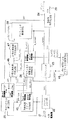
図2に示す第1の構成例のMPEGエンコーダ5において、入力端子21から入力されるディジタル動画像信号S30は、フレームメモリ群22に送られ、記憶される。
【0048】
このフレームメモリ群22に記憶された画像データS23を用いて、動きベクトル検出回路25は、フレーム間の動きベクトルを検出する。具体的に言うと、動きベクトル検出回路25では、フレームを小ブロックに分割し、この小ブロック単位に動きベクトルMVを計算する。ここで、小ブロックは例えば16画素×16ラインで構成されており、動きベクトル検出は例えば参照フレームと現在の小ブロックとのパターンマッチングで行う。すなわち、式(1) に示すように、現在の小ブロックの信号Aijと、任意の動きベクトルにより参照される小ブロックの信号Fijの差の絶対値の和Ef を求める。
【0049】
Ef = Σ|Aij−Fij| (i=0〜15, j=0〜15) (1)
動きベクトル検出回路25は、上記Ef の値が最小となる動きベクトルを動きベクトル信号MVとして出力する。
【0050】
画像データS23と動きベクトル信号MVは、符号化難易度測定回路27へ入力され、ここで入力画像の小ブロック毎に、その符号化難易度d(d_current) が計算される。この第1の構成例での符号化難易度dは、後述する動画像符号化回路24での発生符号量を定められたビットレートに圧縮する時の難易度を表すパラメータである。符号化難易度測定回路27の具体的な構成例については、後述する。
【0051】
次に、プリフィルタ制御回路28へは、上述のように求めた現在の符号化対象の小ブロックの符号化難易度dが入力される。
【0052】
また、プリフィルタ制御情報記憶回路26には、過去に入力された小ブロックで使われたプリフィルタ係数が記憶されている。ここで、このプリフィルタ制御情報記憶回路26には、現在の小ブロックのフレーム上での位置を表すブロックアドレスmb_addressと現在の小ブロックの動きベクトル信号MVとが入力され、それらに基づいて、このプリフィルタ制御情報記憶回路26では、現在の小ブロックがフレーム間予測で参照する小ブロックで使用されたローパスプリフィルタの通過帯域制限を指定するパラメータとしてのフィルタ係数k_refを読み出す。このフィルタ係数k_refは、プリフィルタ制御回路28へ入力される。なお、上記フィルタ係数k_refを読み出す場合には、ブロックアドレスmb_addressだけを使用して、フレーム間予測で参照するフレーム上の同じブロックアドレスmb_addressの位置にある小ブロックで使用されたローパスプリフィルタの通過帯域制限を指定するパラメータを上記フィルタ係数k_refとして読み出すようにしても良い。この場合は、プリフィルタ制御情報記憶回路26へ動きベクトル信号MVを入力する必要はない。
【0053】
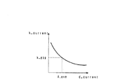
プリフィルタ制御回路28は、上記符号化難易度dとフィルタ係数k_refが入力されると、これらに基づいて、現在の小ブロックに使用するローパスプリフィルタの通過帯域制限を指定するパラメータとしてフィルタ係数k_currentを生成出力し、これをプリフィルタ23へ入力する。ここで、当該プリフィルタ23の特性は、図46に示すような特性とする。従って、ここでは、フィルタ係数k_currentが小さいほど、通過帯域の狭いローパスフィルタ特性とする。
【0054】
なお、プリフィルタ23の特性は、図46に示した特性のローパスフィルタに限らず、これ以外の特性をもつローパスフィルタであってもよい。
【0055】
プリフィルタ制御回路28で計算されたフィルタ係数k_currentは、また、プリフィルタ制御情報記憶回路26へ入力されて記憶され、これが未来に入力される小ブロックに使うプリフィルタ係数を決定する時の参照値(フィルタ係数k_ref)として利用されることになる。
【0056】
フィルタ係数k_currentの計算方法の例について以下に説明する。ここでは、図3に示すように入力動画像の入力順にNフレーム毎(N≧1)のグループを作り、このグループを処理の1単位としている。以下、図4のフローチャートを用いて、プリフィルタ係数の制御について説明する。
【0057】
図4に示すフローチャートにおいて、先ず、ステップST11では、現在の符号化対象のフレームを含むNフレーム間でのフィルタの制御を開始する。
【0058】
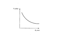
ステップST12では、そのNフレーム間での符号化難易度の平均値d_aveを計算し、次のステップST13では、そのNフレーム間でのプリフィルタ係数の代表値k_gopを計算する。プリフィルタ係数の代表値k_gopは、Nフレーム間での符号化難易度の平均値d_aveに対して、代表的な(平均的な)プリフィルタ係数への対応が、予め経験的に決められている。ここでは、図46で示すように、符号化難易度が大きいほど、通過帯域の狭いローパスフィルタ特性を対応付けておく(すなわちk_gopが小さくなる)。上記符号化難易度の平均値d_aveとプリフィルタ係数の代表値k_gopの対応関係は、例えば図5に示すようになる。
【0059】
次に、ステップST14では、1フレーム内でのフィルタの制御を開始する。
【0060】
先ず、ステップST15では、現在の符号化対象の小ブロックの符号化難易度d(以下d_currentとする)を読み込み、ステップST16では、図3に示すように現在の小ブロックがフレーム間予測で参照する小ブロックで使用されたローパスプリフィルタ係数k_refを読み込む。
【0061】
次に、ステップST17では、上記符号化難易度d_current とローパスプリフィルタ係数k_refから現在の小ブロックで使用するローパスプリフィルタ係数k_currentを計算する。
【0062】
上記ローパスプリフィルタ係数k_currentの計算例を図6に示す。この図6に示す計算例では、先ず、式(a) のように、上記d_currentとk_gopとから統計的にk_currentを仮に計算するが、ここでは、上記d_currentが上記d_aveより大きければ、上記k_currentは上記k_gopよりも小さくなり(すなわち通過帯域の狭いローパスフィルタ特性となり)、逆に、上記d_currentが上記d_aveより小さければ、上記k_currentは上記k_gopよりも大きくなる(すなわち通過帯域の広いローパスフィルタ特性となる)。上記符号化難易度d_currentと上記ローパスプリフィルタ係数k_currentとの対応関係は、例えば図7に示すようになる。この図6に示す計算例では、次に、条件(b)及び条件(c)のように、上記ローパスプリフィルタ係数k_currentと現在の小ブロックがフレーム間予測で参照する小ブロックで使用されたローパスプリフィルタ係数k_refとを比較する。そして、上記k_currentとk_refの変化が、予め決めた閾値より大きい時は、その変化を抑えるように制御する。具体的には、図6に示す計算例では、条件(b) のように、上記k_currentがk_refのA倍(A>1)より大きい時は、当該k_currentをA倍のk_refへ変更する。また、条件(c) のように、上記k_currentが上記k_refのB倍(B<1)より小さい時は、上記k_currentをB倍のk_refへ変更する。以上のようにして、現在の小ブロックで使用するローパスプリフィルタ係数k_currentを計算する。
【0063】
図4のフローチャートに戻って、上述したステップST17の次のステップST18では、現在の小ブロックがフレーム内の最後のブロックであるか否かの判定をする。このステップST18の判定において、現在の小ブロックがフレーム内の最後のブロックでないと判定した場合は、ステップST15へ戻る。一方、このステップST18の判定において、現在の小ブロックがフレーム内の最後のブロックであると判定した場合は、ステップST19へ進む。
【0064】
ステップST19では、現在のフレームがNフレームからなるグループの最後のフレームであるか否かの判定をする。このステップST19の判定において、現在のフレームがNフレームからなるグループの最後のフレームでないと判定した場合はステップST14へ戻り、一方、現在のフレームがNフレームからなるグループの最後のフレームであると判定した場合はステップST20に進む。
【0065】
このステップST49にて、Nフレームからなるグループでのフィルタの制御を終了する。
【0066】
以上のようにして、プリフィルタ制御回路28は、プリフィルタ係数k_currentを決定する。
【0067】
なお、図4のフローチャートにおけるステップST16,ST17において、上記フィルタ係数k_refを使用する代わりに、現在の小ブロックがフレーム間予測で参照する小ブロックの符号化難易度d_refを使用しても良い。
【0068】
この場合のプリフィルタ係数k_currentの計算方法の例について、図8に示すフローチャートを用いて説明する。この図8のフローチャートにおいて前述の図4のフローチャートとの違いは、ステップST26とステップST27であり、それぞれ図4ではステップST16とステップST17に対応する。なお、この図8におけるステップST21からステップST25までは、図4におけるステップST11からステップST15の場合と同じであり、図8のステップST28以降も図4のステップST18以降と同じであるので、それらのステップの説明は省略する。
【0069】
この図8のフローチャートにおいて、ステップST26では、図3に示したように現在の小ブロックがフレーム間予測で参照する小ブロックの符号化難易度d_refを読み込む。
【0070】
次にステップST27では、現在の符号化対象の小ブロックの符号化難易度d_currentと上記符号化難易度d_refから現在の小ブロックで使用するローパスプリフィルタ係数k_currentを計算する。
【0071】
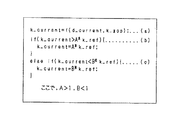
図9には、当該ローパスプリフィルタ係数k_currentの計算例を示す。この図9に示す計算例では、条件(d) と条件(e) のように、上記現在の符号化対象の小ブロックの符号化難易度d_currentと現在の小ブロックがフレーム間予測で参照する小ブロックで使用された符号化難易度d_refとを比較する。そして、d_currentとd_refの変化が、予め決めた閾値より大きい時は、その変化を抑えるように制御する。具体的には、条件(d) のように、上記d_currentが上記d_refのC倍(C>1)より大きい時は、当該d_currentをC倍のd_refへ変更する。また、条件(e) のように、上記d_currentが上記d_refのD倍(D<1)より小さい時は、当該d_current をD倍のd_ref へ変更する。以上のようにして、現在の小ブロックで使用する符号化難易度d_currentを検査する。次に、図9の式(f) のように、上記d_currentとk_gopとから統計的にk_currentを仮に計算する。
【0072】
上述した図9のフローチャートの場合、図2のプリフィルタ制御情報記憶回路26には、過去に計算された小ブロックの符号化難易度d_refが記憶されていて、現在の小ブロックのブロックアドレスmb_addressと動きベクトル信号MVからフレーム間予測で参照する小ブロックの符号化難易度d_refを読み出す。
【0073】
なお、この時、前述したように、上記符号化難易度d_refを読み出す場合に、ブロックアドレスmb_addressだけを使用して、フレーム間予測で参照するフレーム上の同じブロックアドレスmb_addressの位置にある小ブロックで使用されたローパスプリフィルタの通過帯域制限を指定するパラメータをフィルタ係数d_ref として読み出しても良い。この場合は、プリフィルタ制御情報記憶回路26へ動きベクトル信号MVを入力する必要がない。
【0074】
図2に戻って、プリフィルタ23は、現在の小ブロックに対して、プリフィルタ係数k_currentで指定されるローパスフィルタ処理を施して、処理画像信号S22を出力する。
【0075】
当該処理画像信号S22とその動きベクトル信号MVは、動画像符号化回路24へ入力され、ここで所定のフレーム間予測符号化処理が施され、符号化ビットストリームS24として出力端子29から出力される。
【0076】
図10は、図2の動画像符号化回路24の構成例を示したものである。なお、この図10には、動画像符号化回路24の具体例として、例えばいわゆるMPEG方式のような動き補償フレーム間予測とDCTとを組み合わせたハイブリッド符号化を行うものを示している。
【0077】
この図10において、入力端子30には前記動きベクトル検出回路25から入力される動きベクトル信号MVが供給される。一方、入力端子31からは、当該動画像符号化回路(ハイブリッド符号化器)24への入力動画像信号S65が供給される。
【0078】
また、当該動画像符号化回路24の動き補償フレーム間/内予測回路32は、画像メモリを備え、上記入力端子30からの動きベクトル信号MVに基づいて当該画像メモリから読み出した予測画像信号S68を出力する。
【0079】
演算器33は、上記入力端子31からの入力動画像信号S65を加算信号とし、上記動き補償フレーム間/内予測回路32からの上記予測画像信号S68を減算信号として加算処理を行うことにより、上記入力動画像信号S65と予測画像信号S68の差分を計算し、当該差分を予測残差信号S66として出力する。なお、シーンチェンジがあった時は予測を行わず、入力動画像信号S65がそのまま取り出される。
【0080】
次に、予測残差信号S66(予測を行わない時は原信号)は、DCT回路34に送られる。このDCT回路34では上記予測残差信号S66に対して2次元DCTを施す。このDCT回路34から出力されたDCT係数は、量子化回路35にてスカラー量子化される。この量子化回路35の量子化出力信号は、可変長符号化(VLC)回路36と逆量子化回路37とに送られる。VLC回路36では、上記量子化出力信号に対して例えばハフマン符号化を施す。このVLC回路36の出力信号はバッファメモリ38に送られる。当該バッファメモリ38では出力端子31から伝送路に出力するデータ列のビットレートを平滑化する。また、当該バッファメモリ38がオーバーフローしそうになった時には、そのことを量子化制御情報として量子化回路35にフィードバックする。このとき、量子化回路35では量子化ステップを大きくし、これにより量子化回路35から出力される情報量が小さくなされる。
【0081】
一方、逆量子化回路37では、量子化回路35より供給される量子化ステップ情報q_step に対応して、上記量子化出力信号に逆量子化処理を施す。当該逆量子化回路37の出力は、逆DCT回路39に入力され、ここで逆DCT処理されて復号された予測残差信号S67が、演算器40へ入力される。
【0082】
また、この演算器40には、演算器33に供給されている予測画像信号S68と同一の信号が供給されている。演算器40は、上記予測残差信号S67に予測画像信号S68を加算する。これにより、局所復号した画像信号が得られる。この画像信号は、受信側での出力画像と同じ信号である。
【0083】
次に、図11には、図2の符号化難易度測定回路27の構成例を示す。この図11の構成は、基本的には図10で説明した動画像符号化回路24と同じであり、異なる点は、量子化回路41で固定の量子化スケールが使用される点と、VLC回路36からの発生符号量についてバッファメモリの占有量の管理をしない点である。すなわち、VLC回路36からの発生符号量は、カウンタ42にて、小ブロック毎にビット量が数えあげられ、符号化難易度dが出力端子43から出力される。
【0084】
以上のような構成の動画像符号化回路24では、入力動画像信号S30の現在の符号化対象となっているフレームを、少なくとも1画素からなる小ブロックに分割し、この小ブロック単位に符号化難易度(動画像符号化装置の発生符号量を定められたビットレートに圧縮する時の難易度を表すパラメータ)を計算し、当該現在の符号化対象の小ブロックに対してローパスプリフィルタ処理を施す場合に、現在の小ブロックの符号化難易度と現在の小ブロックがフレーム間予測で参照する小ブロックで使われたプリフィルタ制御情報とに基づいて適応的にローパスプリフィルタの特性を決定し、この特性によりローパスプリフィルタ処理した動画像信号に対して符号化処理を施す。
【0085】
すなわち、本発明の第1の構成例の動画像符号化回路24では、フレーム間予測符号化を施す動画像信号に対するプリフィルタ処理の際のフィルタ特性を決定する場合に、現在の符号化対象の小ブロックの符号化難易度とともに、フレーム間予測で参照される小ブロックで使われたプリフィルタ制御情報を合わせて考慮している。
【0086】
具体的には、先ず第1段階として、視覚特性を考慮して、局所的に速い動きや複雑な絵柄であって符号化難易度の大きい部分では、通過帯域の比較的狭いローパスフィルタを選択し、一方、遅い動きや平坦な絵柄であって符号化難易度の小さい部分では、通過帯域の比較的広いローパスフィルタを選択するようにしている。次に第2段階として、現在の符号化対象の小ブロックがフレーム間予測で参照する小ブロックで使われたプリフィルタ制御情報を考慮して、フレーム間予測符号化効率が低下しないように、第1段階で選択されたフィルタ特性を修正して、最終的に現在の符号化対象の小ブロックに対するプリフィルタ特性を決定するようにしている。これにより、ローパスプリフィルタ処理された動画像は、符号化画質の主観的印象が良く、かつ符号化効率の良いものとなる。
【0087】
次に、MPEGエンコーダ5の第2の構成例の動画像符号化装置を図12に示す。
【0088】
この図12に示す第2の構成例において、上述した第1の構成例の動画像符号化回路24との大きな違いは、プリフィルタ制御回路28に入力する符号化難易度d(d_current)として、動きベクトル検出回路44から出力される予測残差、すなわち前述の式(1) で計算される、現在のブロックの信号Aijと任意の動きベクトルにより参照されるブロックの信号Fijの差の絶対値の和Ef を用いている点である。なお、以下に説明する第2の構成例については、MPEGエンコーダ5と同一部分については同一符号を符することでその説明を省略する。
【0089】
この図12において、入力端子21から入力されるディジタル動画像信号S100は、フレームメモリ群22に送られ、記憶される。このフレームメモリ群22に記憶された画像データS103を用いて、動きベクトル検出回路44は、フレーム間の動きベクトルを前記第1の構成例で説明したように検出する。そして、動きベクトル検出回路44は、入力画像の小ブロック毎に動きベクトル信号MVと上述の式(1)から計算される予測残差Efを計算する。当該予測残差Efは、その小ブロックの符号化難易度dとして、動きベクトル検出回路44から出力される。
【0090】
プリフィルタ制御回路28へは、現在の符号化対象の小ブロックの符号化難易度dが入力される。また、プリフィルタ制御情報記憶回路26には、過去に入力された小ブロックで使われたプリフィルタ係数が記憶されている。ここで、このプリフィルタ制御情報記憶回路26には、現在の小ブロックのフレーム上での位置を表すブロックアドレスmb_addressと現在の小ブロックの動きベクトル信号MVが入力され、このプリフィルタ制御情報記憶回路26では、これらに基づいて現在の小ブロックがフレーム間予測で参照する小ブロックで使用されたローパスプリフィルタの通過帯域制限を指定するパラメータとしてフィルタ係数k_refを読み出し、これをプリフィルタ制御回路28へ入力する。なお、フィルタ係数k_refを読み出す場合は、ブロックアドレスmb_addressだけを使用して、フレーム間予測で参照するフレーム上の同じブロックアドレスmb_addressの位置にある小ブロックで使用されたローパスプリフィルタの通過帯域制限を指定するパラメータをフィルタ係数k_refとして読み出しても良い。この場合は、プリフィルタ制御情報記憶回路26へ動きベクトル信号MVを入力する必要はない。
【0091】
プリフィルタ制御回路28は、上記符号化難易度dとフィルタ係数k_refが入力されると、これらの基づいて現在の小ブロックに使用するローパスプリフィルタの通過帯域制限を指定するパラメータとしてフィルタ係数k_currentを生成出力し、これをプリフィルタ23へ入力する。ここで、当該プリフィルタ23の特性は、例えば前述した図45のような特性とする。したがって、ここでは、上記フィルタ係数k_currentが小さいほど、通過帯域の狭いローパスフィルタ特性となる。
【0092】
なお、プリフィルタ23の特性は、図45に示した特性のローパスフィルタに限らず、これ以外の特性をもつローパスフィルタであってもよい。
【0093】
プリフィルタ制御回路23で計算されたフィルタ係数k_currentは、また、プリフィルタ制御情報記憶回路26へ入力されて記憶され、これが未来に入力される小ブロックに使うプリフィルタ係数を決定する時の参照値k_refとして利用されることになる。
【0094】
なお、フィルタ係数k_currentの計算方法の例は、第1の構成例において図6を用いて説明した方法と同様である。
【0095】
プリフィルタ23は、現在の小ブロックに対して、プリフィルタ係数k_currentで指定されるローパスフィルタ処理を施して、処理画像信号S102を出力する。
【0096】
当該処理画像信号S102とその動きベクトル信号MVは、動画像符号化回路24へ入力され、所定のフレーム間予測符号化処理(例えばいわゆるMPEG方式の符号化処理)が施され、この符号化ビットストリームS104が出力端子29から出力される。なお、動画像符号化回路24の構成は、第1の構成例において図10を用いて説明したものと同様である。
【0097】
このような構成の動画像符号化装置では、プリフィルタ制御回路28に入力する符号化難易度d(d_current)として、動きベクトル検出回路44から出力される予測残差、すなわち、現在のブロックの信号Aijと任意の動きベクトルにより参照されるブロックの信号Fijの差の絶対値の和Ef を用いることにより、フレーム間予測符号化効率が低下しないように、選択されたフィルタ特性を修正して、最終的に現在の符号化対象の小ブロックに対するプリフィルタ特性を決定する。これにより、ローパスプリフィルタ処理された動画像は、符号化画質の主観的印象が良く、かつ符号化効率の良いものとすることできる。
【0098】
なお、特開平6−225276号公報に開示されている動画像符号化におけるプリフィルタ制御方法及び装置も、入力画像信号に対してプリフィルタ処理を行うようにしているが、この公報記載の技術は、1画面内でプリフィルタ係数を変えることは行っておらず画面内では一定で、また複数フレーム単位でフィルタ係数を一定にしている。
【0099】
これに対して、上述のような第1の構成例や第2の構成例の動画像符号化回路では、フレーム間予測符号化を施す動画像信号に対するプリフィルタ処理の際のフィルタ特性を、画面を分割する小ブロック単位の符号化難易度dに応じて適応的に変更可能としているので、視覚特性を考慮して、画面内の局所的に速い動きや複雑な絵柄であり符号化難易度の大きい部分では通過帯域の比較的狭いローパスフィルタを選択でき、一方、遅い動きや平坦な絵柄であり符号化難易度の小さい部分では通過帯域の比較的広いローパスフィルタを選択できる。さらにこの小ブロック単位のプリフィルタ係数を決定する場合には、上記小ブロックの符号化難易度dだけでなく、現在の符号化対象の小ブロックがフレーム間予測で参照する小ブロックで使われたプリフィルタ制御情報をも合わせて考慮しており、フレーム間予測符号化効率が低下しないように、上述のように選択されたフィルタ特性を修正して、最終的に現在の符号化対象の小ブロックに対するプリフィルタ特性を決定するようにしているので、ローパスプリフィルタ処理された動画像は、従来よりも、符号化画質の主観的印象が良く、かつ符号化効率の良いものとすることできる。
【0100】
ところで、MPEG方式などで用いられているフレーム間予測符号化では、図13に示すように予測を行わないで内部符号化するIピクチャと、順方向予測のみを行うPピクチャと、双方向予測を行うBピクチャがあり、一般に、これらの画像間では符号化難易度のダイナミックレンジや小ブロック毎の符号化難易度の分布が異なっている。MPEG方式では、このように符号化難易度の特性の異なる画像が連続しているため、全入力画像の符号化難易度に従ってローパスフィルタ処理のフィルタ特性を決定すると、時間的に近接する画像間でフィルタ特性が極端に異なることに起因する主観的画質の劣化が生じる可能性がある。
【0101】
上述の第1及び第2の構成例により説明した動画像符号化回路においては、入力画像の小ブロックの符号化難易度と当該小ブロックが画像間予測で参照する小ブロックで使われたフィルタ制御情報とに基づいて、ローパスフィルタ処理のフィルタ特性を決定しているが、内部符号化を行うIピクチャや、フィルタ特性の参照画像との間にBピクチャが存在するPピクチャ及び時間的に連続する画像間のフィルタ特性に関して考慮していない。
【0102】
また、フレーム間予測を行う画像において、予測を行わずに内部符号化を行う小ブロックが存在することがあるため、同一画像内においても、空間的に近接する小ブロックと比較して、極端に符号化難易度の高い小ブロックが存在することがある。
【0103】
このような画像に対して、小ブロック毎の符号化難易度に従って適応的にローパスフィルタ処理のフィルタ特性を決定すると、時間的/空間的に局所的にローパスの通過帯域の異なる小ブロックが存在することになり、主観的画質の劣化が生じる可能性がある。
【0104】
そこで、図14に示す本発明の第3の構成例の動画像符号化回路では、フレーム間予測符号化を施す動画像信号に対するプリフィルタ処理の際のフィルタ特性を決定する場合に、入力動画像信号S30の現在の符号化対象となっているフレームを、少なくとも1画素からなる小ブロックに分割し、現在の符号化対象の画像がフィルタ特性画像であるか非フィルタ特性画像であるかの判定を行い、現在の小ブロックのプリフィルタ情報とともに、フレーム間予測で参照される小ブロックで使われたプリフィルタ制御情報及び時間的に近接する画像の空間的に同じ位置の小ブロックで使われたプリフィルタ制御情報を合わせて考慮している。なお、以下の第3の構成例の説明においては、上述の第1の構成例と同一の部分については同一符号を付することでその説明を省略する。
【0105】
具体的には、先ず第1段階として、MPEG方式における、I、P、Bピクチャなどの符号化タイプによって符号化難易度が異なることを考慮して、特定の符号化タイプの入力画像をフィルタ特性画像として判定し、それ以外の符号化タイプの画像を非フィルタ特性画像として判定する。ここで、例えばフィルタ特性画像にはPピクチャを用い、非フィルタ特性画像にはI、Bピクチャを用いる。
【0106】
入力画像をフィルタ特性画像として判定した場合は所定の方法で当該画像の小ブロック毎の符号化難易度を計算し、所定の方法で当該画像内で当該符号化難易度を平滑化する。
【0107】
第2段階として視覚特性を考慮して、局所的に速い動きや複雑な絵柄であるために符号化難易度の大きい小ブロックでは、通過帯域の比較的狭いローパスフィルタを選択し、一方、遅い動きや平坦な絵柄であるために符号化難易度の小さい小ブロックでは、通過帯域の比較的広いローパスフィルタを選択するようにしている。更に、現在の符号化対象の小ブロックがフレーム間予測で参照する小ブロックで使われたプリフィルタ制御情報を考慮し、主観的に画質が劣化せず、かつ、フレーム間予測符号化効率が低下しないように、選択されたフィルタ特性を修正して、現在の符号化対象の小ブロックに対するプリフィルタ特性を決定する。非フィルタ特性画像の場合は、第2段階として現在の符号化対象の小ブロックがフレーム間予測で参照する過去参照画像の小ブロックで使われたプリフィルタ制御情報と未来参照画像の小ブロックで使われたプリフィルタ制御情報から所定の方法で内挿補間を行い当該画像の小ブロックのプリフィルタ特性を算出する。更に、時間的に近接する画像の空間的に同じ位置の小ブロックで使われたプリフィルタの制御情報を考慮して、主観的に画質が劣化せず、かつ、フレーム間予測符号化効率が低下しないように、算出したフィルタ特性を修正して、現在の符号化対象の小ブロックに対するプリフィルタ特性を決定する。
【0108】
ここで、非フィルタ特性画像が予測を用いない内部符号化画像、例えばMPEG方式におけるIピクチャである場合には、時間的に前後するPピクチャの空間的に同じ位置の小ブロックのプリフィルタ制御情報に基づいて内挿補間を行い、現在の符号化対象の小ブロックのプリフィルタ特性を決定する。
【0109】
これらにより、ローパスプリフィルタ処理された動画像は、符号化画質の主観的印象が良く、かつ符号化効率の良いものとなる。
【0110】
この図14に示す本発明の第3の構成例の動画像符号化回路において、入力端子21から入力されるディジタル動画像信号S30は、フレームメモリ群22に送られ、記憶される。
【0111】
MPEG方式においては、予測符号化を行う際に、双方向予測を行うことから、図15(a),(b)に示すように画像の入力順序と符号化順序が異なるため、フレームメモリ群22では符号化順序に従って入力画像の順序入替えを行う。このフレームメモリ群22に記憶された画像データS23を用いて、動きベクトル検出回路25は、フレーム間の動きベクトルを検出する。具体的に言うと、動きベクトル検出回路25では、フレームを小ブロックに分割し、この小ブロック単位に動きベクトルMVを計算する。ここで、小ブロックは例えば16画素×16ラインで構成されており、動きベクトル検出は例えば参照フレームと現在の小ブロックとのパターンマッチングで行う。すなわち、上述の式(1) により、現在の小ブロックの信号Aijと、任意の動きベクトルにより参照される小ブロックの信号Fijの差の絶対値の和Ef を求める。
【0112】
動きベクトル検出回路25は、上記Ef の値が最小となる動きベクトルを動きベクトル信号MVとして出力する。
【0113】
画像処理タイプ判定回路45では、入力された画像データS23のピクチャータイプによって、出力する回路切替え信号pict_type の内容を変え、以降の処理を変える。
【0114】
画像データS23がフィルタ特性画像として用いる画像、例えばPピクチャ、であったならば、画像データS23を符号化難易度測定回路46に入力し、回路切替え信号pict_type(1)を動きベクトル検出回路25及びプリフィルタ制御情報記憶回路26に入力する。
【0115】
回路切替え信号pict_type(1)を入力された動きベクトル検出回路25では、動きベクトル信号MVを動画像符号化回路24、プリフィルタ制御情報記憶回路26及び符号化難易度測定回路46に入力する。
【0116】
画像データS23と動きベクトル信号MVを入力された符号化難易度測定回路46では、入力画像の小ブロック毎に、その符号化難易度d(d_raw) を計算する。
【0117】
この第3の構成例での符号化難易度d(d_raw) 、後述する動画像符号化回路24での発生符号量を定められたビットレートに圧縮する時の難易度を表すパラメータである。符号化難易度測定回路46の具体的な構成例については、後述する。
【0118】
符号化難易度平滑化回路47では、近接する小ブロック間で、フィルタ係数が極端に異なることを避けるために、入力したd(d_raw) をフレーム内で平滑化し、平滑化符号化難易度情報d(d_current) を計算する。符号化難易度平滑化回路47では、横方向にi番目、縱方向にj番目の現在の符号化対象の小ブロックの符号化難易度をd(i,j)としたとき、 例えば次の式(2)

【0119】
次に、プリフィルタ制御回路28へは、上述のように求めた現在の符号化対象の小ブロックの符号化難易度d(d_current) が入力される。
【0120】
また、プリフィルタ制御情報記憶回路26には、過去に入力された小ブロックで使われたプリフィルタ係数が記憶されている。
【0121】
ここで、このプリフィルタ制御情報記憶回路26には、現在の小ブロックのフレーム上での位置を表すブロックアドレスmb_address と現在の小ブロックの動きベクトル信号MV及び回路切替え信号pict_type(1)が入力され、それらに基づいて、このプリフィルタ制御情報記憶回路26では、現在の小ブロックがフレーム間予測で参照する小ブロックで使用されたローパスプリフィルタの通過帯域制限を指定するパラメータとしてのフィルタ係数k_ref(1)を読み出し、プリフィルタ制御回路28へ入力する。
【0122】
なお、上記フレーム間予測で参照する小ブロックのフィルタ係数k_ref(1)を読み出す場合には、ブロックアドレスmb_address だけを使用して、フレーム間予測で参照するフレーム上の同じブロックアドレスmb_addressの 位置にある小ブロックで使用されたローパスプリフィルタの通過帯域制限を指定するパラメータを上記フィルタ係数k_ref(1)として読み出すようにしても良い。この場合は、プリフィルタ制御情報記憶回路26へ動きベクトル信号MVを入力する必要はない。
【0123】
プリフィルタ制御回路28は、上記符号化難易度d(d_current) とフィルタ係数k_ref(1)が入力されると、これらに基づいて、現在の小ブロックに使用するローパスプリフィルタの通過帯域制限を指定するパラメータとしてフィルタ係数k_current を生成出力し、これをプリフィルタ23へ入力する。
【0124】
プリフィルタ制御回路28で計算されたフィルタ係数k_current は、また、プリフィルタ制御情報記憶回路26へ入力されて記憶され、これが未来に入力される小ブロックに使うプリフィルタ係数を決定する時の参照値(フィルタ係数k_ref) として利用されることになる。
【0125】
次に、画像データS23が非フィルタ特性画像、例えばMPEG方式におけるI、Bピクチャ、であったならば、画像処理タイプ判定回路45は現在の小ブロックのフレーム上での位置を表すブロックアドレスmb_address をプリフィルタ制御情報記憶回路26に入力し、回路切替え信号pict_type(2)を動きベクトル検出回路25及びプリフィルタ制御情報記憶回路26に入力する。
【0126】
回路切替え信号pict_type(2)を入力された動きベクトル検出回路25では、動きベクトル信号MVを動画像符号化回路24及びプリフィルタ制御情報記憶回路26に入力する。
【0127】
現在の小ブロックのブロックアドレスmb_address と現在の小ブロックの動きベクトルMVを入力されたプリフィルタ制御情報記憶回路26は現在の小ブロックがフレーム間予測で参照する未来参照画像と過去参照画像の小ブロックで使用されたローパスプリフィルタの通過帯域制限を指定するパラメータとしてのフィルタ係数k_ref(2)、k_ref(3)と時間的に近接する画像の空間的に同じ位置の小ブロックで使用されたローパスプリフィルタの通過帯域制限を指定するパラメータとしてのフィルタ係数k_ref(4)を読み出し、内挿補間回路48に入力する。
【0128】
なお、上記フィルタ係数k_ref(2)、k_ref(3)を読み出す場合には、ブロックアドレスmb_address だけを使用して、フレーム間予測で参照するフレーム上の同じブロックアドレスmb_address の位置にある小ブロックで使用されたローパスプリフィルタの通過帯域制限を指定するパラメータを上記フィルタ係数k_ref(2)、k_ref(3)として読み出すようにしても良い。この場合は、プリフィルタ制御情報記憶回路26へ動きベクトル信号MVを入力する必要はない。
【0129】
現在の小ブロックのパラメータとしてのフィルタ係数k_ref(2)、k_ref(3)、k_ref(4)を入力された内挿補間回路48は、過去参照画像のフィルタ係数k_ref(2)と未来参照画像のフィルタ係数k_ref(3)を基に内挿補間を行い、更に時間的に近接する画像の空間的に同じ位置の小ブロックのフィルタ係数k_ref(4)を用いて現在の小ブロックのフィルタ係数k_current を生成出力し、これをプリフィルタ23へ入力する。
【0130】
ここで、現在の小ブロックと時間的に近接する画像の空間的に同じ位置の小ブロックで使用されたフィルタ係数k_ref(4)を用いず、現在の小ブロックがフレーム間予測で参照する小ブロックで使用されたフィルタ係数k_ref(2)、k_ref(3)のみを読み出して現在の小ブロックのフィルタ係数k_current を生成出力すようにしても良い。
【0131】
また、非フィルタ特性画像が例えばMPEG方式のIピクチャーのように、フレーム間予測を行わない画像であった場合には、時間的に前後するフィルタ特性画像の空間的に同じ位置の小ブロックのフィルタ係数を過去参照画像のフィルタ係数k_ref(2)と未来参照画像のフィルタ係数k_ref(3)として読み出し、内挿補間を行う。この場合は時間的に近接する画像の空間的に同じ位置の小ブロックのフィルタ係数k_ref(4)は用いない。
【0132】
内挿補間回路48で計算されたフィルタ係数k_current は、また、プリフィルタ制御情報記憶回路26へ入力されて記憶され、これが未来に入力される小ブロックに使うプリフィルタ係数を決定する時の参照値(フィルタ係数k_ref )として利用されることになる。
【0133】
以上のようにして、適応的にプリフィルタ23のフィルタ係数を決定し、符号化画質の主観的印象が良く、かつ符号化効率の良い符号化方式を実現する。
【0134】
ここで、当該プリフィルタ23の特性は、例えば上述の図45のような特性とする。したがって、ここでは、フィルタ係数k_current が小さいほど、通過帯域の狭いローパスフィルタ特性となる。また、プリフィルタ23は、上述の図45に示した特性のローパスフィルタやこれ以外の特性をもつローパスフィルタを用いることができる。
【0135】
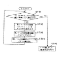
フィルタ係数k_current の計算方法の例について以下に説明する。ここでは、図16に示すように入力動画像の入力順に、フィルタ特性画像、非フィルタ特性画像の双方を含むNフレーム毎(N≧1)のグループを作り、このグループを処理の1単位としている。図17のフローチャートを用いて、プリフィルタ係数の制御について説明する。
【0136】
図17のフローチャートにおいて、先ず、ステップST31では、現在の符号化対象のフレームを含むNフレーム間でのフィルタの制御を開始する。
【0137】
ステップST32では、そのNフレーム間でのフィルタ特性画像の符号化難易度の平均値d_ave を計算し、次のステップST33では、そのNフレーム間でのプリフィルタ係数の代表値k_gop を計算する。プリフィルタ係数の代表値k_gop は、Nフレーム間での符号化難易度の平均値d_ave に対して、代表的な(平均的な)プリフィルタ係数への対応が、予め経験的に決められている。ここでは、上述の図46に示したように、符号化難易度が大きいほど、通過帯域の狭いローパスフィルタ特性を対応付けておく(すなわちk_gop が小さくなる)。上記符号化難易度の平均値d_ave とプリフィルタ係数の代表値k_gop の対応関係は、例えば上述の図5に示すようになる。
【0138】
次に、ステップST34では、現在符号化対象フレームがフィルタ特性画像であるか、非フィルタ特性画像であるかの判定を行う。フィルタ特性画像であるならば、ステップST35へ進み、非フィルタ特性画像であるならば、ステップST42に移る。
【0139】
ステップST35では、フィルタ特性画像の1フレーム内でのフィルタの制御を開始する。先ず、ステップST36では、現在の符号化対象の小ブロックの平滑化した符号化難易度d(以下d_current とする)を読み込み、ステップST37では、図16(a)に示すように現在の小ブロックがフレーム間予測で参照する小ブロックで使用されたローパスプリフィルタ係数k_ref(1)を読み込む。
【0140】
次に、ステップST38では、上記符号化難易度d_current とローパスプリフィルタ係数k_ref(1)から現在の小ブロックで使用するローパスプリフィルタ係数k_current を例えば上述の図9に示した計算例と同様に計算する。
【0141】
次のステップST39では、現在の小ブロックがフレーム内の最後のブロックであるか否かの判定をする。このステップST39の判定において、現在の小ブロックがフレーム内の最後のブロックでないと判定した場合は、ステップST36へ戻る。一方、このステップST39の判定において、現在の小ブロックがフレーム内の最後のブロックであると判定した場合は、ステップST40へ進む。
【0142】
ステップST40では、現在のフレームがNフレームからなるグループの最後のフィルタ特性画像であるか否かの判定をする。このステップST40の判定において、現在のフレームがNフレームからなるグループの最後のフィルタ特性画像でないと判定した場合はステップST34へ戻り、一方、現在のフレームがNフレームからなるグループの最後のフィルタ特性画像であると判定した場合はステップST41に進む。
【0143】
ステップST42では、非フィルタ特性画像の1フレーム内でのフィルタの制御を開始する。先ず、ステップST43では、図16(b)に示すように現在の小ブロックがフレーム間予測で参照する、過去参照画像と未来参照画像の小ブロックで各々使用されたローパスプリフィルタ係数k_ref(2)とk_ref(3)を読み込み、ステップST44では、図16(b)に示すように時間的に近接するフレームの空間的に同じ位置の小ブロックで使用されたローパスプリフィルタ係数k_ref(4)を読み込む次に、ステップST54では、上記フィルタ係数k_ref(2)とk_ref(3)とk_ref(4)から現在の小ブロックで使用するローパスプリフィルタ係数k_currentを計算する。
【0144】
図18に上記ローパスプリフィルタ係数k_current の計算例を示す。現在の符号化対象画像と過去参照画像、未来参照画像が図16(b)に示すような位置関係である場合、図18に示す計算例では、先ず、式(g) のように、上記k_ref(2)とk_ref(3)からk_current を各々の画像の距離に従った内挿補間によって計算する。次に、条件(h)及び条件(i)のように、現在の符号化対象画像の小ブロックと時間的に近接する画像の空間的に同じ位置の小ブロックで使用されたローパスプリフィルタ係数k_ref(4)とを比較する。そして、上記k_current とk_ref(4)の変化が、予め決めた閾値より大きい時は、その変化を抑えるように制御する。
【0145】
具体的には、図18に示す計算例では、条件(h) のように、上記k_current がk_ref(4)のE倍(E>1)より大きい時は、当該k_current をE倍のk_ref(4)へ変更する。また、条件(i) のように、上記k_current が上記k_ref(4)のF倍(D<1)より小さい時は、上記k_current をF倍のk_ref(4)へ変更する。以上のようにして、現在の小ブロックで使用するローパスプリフィルタ係数k_current を決定する。
【0146】
また、非フィルタ特性画像がIピクチャである場合は、過去参照画像の同じ位置の小ブロックで使用したローパスフィルタ係数をk_ref(2)とし、未来参照画像の同じ位置の小ブロックで使用したローパスフィルタ係数をk_ref(3)として同様に計算する。
【0147】
図17のフローチャートに戻って、上述したステップST45の次のステップST46では、現在の小ブロックがフレーム内の最後のブロックであるか否かの判定をする。このステップST46の判定において、現在の小ブロックがフレーム内の最後のブロックでないと判定した場合は、ステップST43へ戻る。一方、このステップST46の判定において、現在の小ブロックがフレーム内の最後のブロックであると判定した場合は、ステップST47へ進む。
【0148】
ステップST47では、現在のフレームがNフレームからなるグループの最後の非フィルタ特性画像であるか否かの判定をする。このステップST47の判定において、現在のフレームがNフレームからなるグループの最後の非フィルタ特性画像でないと判定した場合はステップST47へ戻り、一方、現在のフレームがNフレームからなるグループの最後の非フィルタ特性画像であると判定した場合はステップST41に進む。
【0149】
このステップST41にて、Nフレームからなるグループでのフィルタの制御を終了する。
【0150】
以上のようにして、プリフィルタ制御回路28及び、内挿補間回路48では、プリフィルタ係数k_current を決定する。
【0151】
なお、図17のステップST37,ST38,ST43,ST44,ST45において、上記フィルタ係数k_ref(1),k_ref(2),k_ref(3),k_ref(4)を使用する代わりに、現在の小ブロックがフレーム間予測で参照する小ブロックの符号化難易度d_ref(1),d_ref(2),d_ref(3),d_ref(4)を使用しても良い。
【0152】
なお、この場合は、画像処理タイプ判定回路45において入力画像を非フィルタ特性画像と判定した場合でも画像データS123を符号化難易度測定回路46に入力し、動きベクトル検出回路25から動きベクトル信号MVを符号化難易度測定回路46に入力して符号化難易度d_ref(4)を計算する必要がある。 この場合のプリフィルタ係数k_current の計算方法の例について、図19を用いて説明する。この図19において前述の図17のフローチャートとの違いは、ステップST57,ST58,ST63,ST64,ST65であり、それぞれ図17ではステップST36,ST38,ST43,ST44,ST45に対応する。なお、この図19のステップST51〜ST56,ステップST59〜ST62,ステップST65以降は各々、図17のステップST31〜ST36,ステップST39〜ステップST42,ステップST46以降と同じであるので、それらのステップの説明は省略する。
【0153】
この図19において、ステップST57では、図16(a)に示したように現在の小ブロックがフレーム間予測で参照する小ブロックの符号化難易度d_ref(1)を読み込む。次にステップST58では、現在の符号化対象の小ブロックの符号化難易度d_current と上記符号化難易度d_ref(1)から現在の小ブロックで使用するローパスプリフィルタ係数k_current を例えば上述の図9に示した計算例と同様に計算する。
【0154】
また、ステップST63では、図16(b)に示すように現在の小ブロックがフレーム間予測で参照する、過去参照画像と未来参照画像の小ブロックで各々使用された符号化難易度d_ref(2)とd_ref(3)を読み込み、ステップST64では、図16(b)に示すように時間的に近接するフレームの空間的に同じ位置の小ブロックで使用されたローパスプリフィルタ係数k_ref(4)を読み込む。
【0155】
図20には上記ローパスプリフィルタ係数k_current の計算例を示す。現在の符号化対象画像と過去参照画像、未来参照画像が図16(b)に示すような位置関係である場合、図20に示す計算例においては、先ず、式(j) のように、上記d_ref(2)とd_ref(3)からd_currentを内挿補間によって計算する。次に、条件(k)及び条件(l)のように、現在の符号化対象画像の小ブロックと時間的に近接する画像の空間的に同じ位置の小ブロックの符号化難易度係数d_ref(4)とを比較する。そして、上記d_current とd_ref(4)の変化が、予め決めた閾値より大きい時は、その変化を抑えるように制御する。
【0156】
具体的には、図20に示す計算例では、条件(k) のように、上記d_current がd_ref(4)のC倍(C>1)より大きい時は、当該d_current をC倍のd_ref(4)へ変更する。また、条件(l) のように、上記d_current が上記d_ref(4)のD倍(D<1)より小さい時は、上記d_current をD倍のd_ref(4)へ変更する。以上のようにして、現在の小ブロックの符号化難易度d_current を決定する。そして、条件(j)のように上記符号化難易度d_current とk_gopから現在の小ブロックで使用するローパスプリフィルタ係数k_current を計算する。
【0157】
また、非フィルタ特性画像がIピクチャである場合は、過去参照画像の同じ位置の小ブロックの符号化難易度をd_ref(2)とし、未来参照画像の同じ位置の小ブロックの符号化難易度をd_ref(3)とする。
【0158】
上述した図19のフローチャートの場合、プリフィルタ制御情報記憶回路26には、過去に計算された小ブロックの符号化難易度d_ref が記憶されていて、現在の小ブロックのブロックアドレスmb_address と動きベクトル信号MVからフレーム間予測で参照する小ブロックの符号化難易度d_ref を読み出す。
【0159】
なお、この時、前述したように、上記符号化難易度d_ref を読み出す場合に、ブロックアドレスmb_address だけを使用して、フレーム間予測で参照するフレーム上の同じブロックアドレスmb_address の位置にある小ブロックで使用されたローパスプリフィルタの通過帯域制限を指定するパラメータをフィルタ係数d_refとして読み出しても良い。この場合は、プリフィルタ制御情報記憶回路26へ動きベクトル信号MVを入力する必要がない。
【0160】
図14に戻って、プリフィルタ23は、現在の小ブロックに対して、プリフィルタ係数k_current で指定されるローパスフィルタ処理を施して、処理画像信号S122を出力する。
【0161】
当該処理画像信号S22とその動きベクトル信号MVは、動画像符号化回路24へ入力され、ここで所定のフレーム間予測符号化処理が施され、符号化ビットストリームS24として出力端子29から出力される。
【0162】
プリフィルタ23の構成例を図21に示す。この図21に示す構成例において、入力端子50には当該プリフィルタ23への入力画像信号S300が供給される。一方、入力端子51にはプリフィルタ制御回路28又は内挿補間によるプリフィルタ制御回路28から入力されるローパスプリフィルタ係数k_current が入力される。
【0163】
ここで、ローパスプリフィルタ係数k_current は、0≦k_current ≦1の値を取るように定める。
【0164】
入力画像信号S300は、ローパスフィルタ52に入力され、ここでローパスフィルタ処理される。ローパスフィルタ52による処理画像信号S301は、演算器53に入力される。演算器53は、処理画像信号S301と入力画像信号S300との差分信号S302を出力する。ここに、
S302=S301−S300
である。
【0165】
次に、差分信号S302は、演算器54に入力される。演算器54は、差分信号S302にローパスプリフィルタ係数k_current を乗算した信号S303を出力する。ここに、
S303=S302×k_current
である。
【0166】
次に、演算器54からの信号S303は、演算器55に入力される。演算器55は、信号S303と入力画像信号S300との加算信号であるプリフィルタ処理画像信号S304を出力する。ここに、
【0167】
また、動画像符号化回路24には、例えば上述の図11に示した構成のものが用いられる。また、符号化難易度測定回路46には、例えば上述の図11に示した構成のものが用いられる。
【0168】
次に、本発明の第4の構成例の動画像符号化回路を図22に示す。
【0169】
この図22に示す第4の構成例において、上述した第3の構成例の動画像符号化回路との大きな違いは、プリフィルタ制御回路67に入力する符号化難易度d(d_current )として、動きベクトル検出回路66から出力される予測残差、すなわち前述の式(1) で計算される、現在のブロックの信号Aijと任意の動きベクトルにより参照されるブロックの信号Fijの差の絶対値の和Ef を用いている点である。
【0170】
この図22において、入力端子60から入力されるディジタル動画像信号S100は、フレームメモリ群61に送られ、記憶される。このフレームメモリ群61に記憶された画像データS103を用いて、動きベクトル検出回路66は、フレーム間の動きベクトルを前記第3の構成例で説明したにように検出する。
【0171】
動きベクトル検出回路66では、入力画像の小ブロック毎に動きベクトル信号MVと上述の式(1) から計算される予測残差Ef を計算し、動きベクトル信号MVを動画像符号化回路63とプリフィルタ制御情報記憶回路65に入力する。
【0172】
画像処理タイプ判定回路64では、入力された画像データの処理番号pict_numberより、現在処理中の画像がフィルタ特性画像であるか非フィルタ特性画像であるかの判定を行う。現在処理中の画像がフィルタ特性画像、例えばPピクチャ、であったならば、回路切替え信号pict_type(1)をフィルタ制御情報記憶回路65と動きベクトル検出回路66に入力する。
【0173】
回路切替え信号pict_type(1) を入力された動きベクトル検出回路66では、予測残差Ef を、その小ブロックの符号化難易度d(d_raw)として出力する。
【0174】
符号化難易度平滑化回路69では、近接する小ブロック間で、フィルタ係数が極端に異なることを避けるために、入力したd(d_raw )をフレーム内で平滑化し、平滑化符号化難易度情報d(d_current )を計算する。符号化難易度平滑化回路69での平滑化処理は第3の構成例と同様に行う。プリフィルタ制御回路67へは、現在の符号化対象の小ブロックの符号化難易度d(d_current) が入力される。また、プリフィルタ制御情報記憶回路65には、過去に入力された小ブロックで使われたプリフィルタ係数が記憶されている。ここで、このプリフィルタ制御情報記憶回路65には、現在の小ブロックのフレーム上での位置を表すブロックアドレスmb_address と現在の小ブロックの動きベクトル信号MV及び、回路切替え信号pict_type(1)が入力される。
【0175】
このプリフィルタ制御情報記憶回路65では、これらに基づいて現在の小ブロックがフレーム間予測で参照する小ブロックで使用されたローパスプリフィルタの通過帯域制限を指定するパラメータとしてフィルタ係数k_ref(1)を読み出し、これをプリフィルタ制御回路67へ入力する。
【0176】
なお、フィルタ係数k_ref(1)を読み出す場合は、ブロックアドレスmb_address だけを使用して、フレーム間予測で参照するフレーム上の同じブロックアドレスmb_address の位置にある小ブロックで使用されたローパスプリフィルタの通過帯域制限を指定するパラメータをフィルタ係数k_ref として読み出しても良い。この場合は、プリフィルタ制御情報記憶回路65へ動きベクトル信号MVを入力する必要はない。
【0177】
プリフィルタ制御回路67は、上記符号化難易度dとフィルタ係数k_ref(1)が入力されると、これらに基づいて現在の小ブロックに使用するローパスプリフィルタの通過帯域制限を指定するパラメータとしてフィルタ係数k_current を生成出力し、これをプリフィルタ62へ入力する。ここで、当該プリフィルタ62の特性は、例えば前述した図45のような特性とする。したがって、ここでは、上記フィルタ係数k_current が小さいほど、通過帯域の狭いローパスフィルタ特性となる。
【0178】
なお、プリフィルタ62の特性は、図45に示した特性のローパスフィルタに限らず、これ以外の特性をもつローパスフィルタであってもよい。
【0179】
プリフィルタ制御回路67で計算されたフィルタ係数k_current は、また、プリフィルタ制御情報記憶回路65へ入力されて記憶され、これが未来に入力される小ブロックに使うプリフィルタ係数を決定する時の参照値k_ref として利用されることになる。
【0180】
また、画像処理タイプ判定回路64において、入力されたpict_number より、現在処理中の画像が非フィルタ特性画像、例えばI、Bピクチャ、であると判定した場合、回路切替え信号 pict_type(2) をフィルタ制御情報記憶回路65と動きベクトル検出回路66に入力し、現在の小ブロックのフレーム上での位置を表すブロックアドレスmb_address をプリフィルタ制御情報記憶回路65と内挿補間回路70に入力する。
【0181】
回路切替え信号 pict_type(2) を入力された動きベクトル検出回路66では、予測残差Ef の出力を行わない。
【0182】
現在の小ブロックのブロックアドレスmb_address と現在の小ブロックの動きベクトルMV及び、回路切替え信号 pict_type(2) を入力されたプリフィルタ制御情報記憶回路65は現在の小ブロックがフレーム間予測で参照する未来参照画像と過去参照画像の小ブロックで使用されたローパスプリフィルタの通過帯域制限を指定するパラメータとしてのフィルタ係数k_ref(2)、k_ref(3)と時間的に近接する画像の空間的に同じ位置の小ブロックで使用されたローパスプリフィルタの通過帯域制限を指定するパラメータとしてのフィルタ係数k_ref(4)を読み出し、内挿補間回路70に入力する。
【0183】
なお、上記フィルタ係数k_ref(2)、k_ref(3)を読み出す場合には、ブロックアドレスmb_address だけを使用して、フレーム間予測で参照するフレーム上の同じブロックアドレスmb_address の位置にある小ブロックで使用されたローパスプリフィルタの通過帯域制限を指定するパラメータを上記フィルタ係数k_ref(2),k_ref(3)として読み出すようにしても良い。この場合は、プリフィルタ制御情報記憶回路65へ動きベクトル信号MVを入力する必要はない。
【0184】
現在の小ブロックの動きベクトル信号MV及び、パラメータとしてのフィルタ係数k_ref(2),k_ref(3),k_ref(4)を入力された内挿補間回路70は、過去参照画像のフィルタ係数k_ref(2)と未来参照画像のフィルタ係数k_ref(3)を基に内挿補間を行い、更に時間的に近接する画像の空間的に同じ位置の小ブロックのフィルタ係数k_ref(4)を用いて現在の小ブロックのフィルタ係数k_current を生成出力し、これをプリフィルタ62へ入力する。
【0185】
ここで、現在の小ブロックと時間的に近接する画像の空間的に同じ位置の小ブロックで使用されたフィルタ係数k_ref(4)を用いず、現在の小ブロックがフレーム間予測で参照する小ブロックで使用されたフィルタ係数k_ref(2)、k_ref(3)のみを読み出して現在の小ブロックのフィルタ係数k_current を生成出力するようにしても良い。
【0186】
また、非フィルタ特性画像が例えばMPEG方式のIピクチャーのように、フレーム間予測を行わない画像であった場合には、時間的に前後するフィルタ特性画像の空間的に同じ位置の小ブロックのフィルタ係数を過去参照画像のフィルタ係数k_ref(2)と未来参照画像のフィルタ係数k_ref(3)として読み出し、内挿補間を行う。この場合は時間的に近接する画像の空間的に同じ位置の小ブロックのフィルタ係数k_ref(4)は用いない。
【0187】
また、Iピクチャーにおいても、動き予測を行っている場合には、Iピクチャーもフィルタ特性画像として用いても良い。ここで、当該プリフィルタ62の特性は、例えば前述した図45のような特性とする。したがって、ここでは、フィルタ係数k_current が小さいほど、通過帯域の狭いローパスフィルタ特性となる。
【0188】
内挿補間回路70で計算されたフィルタ係数k_current は、また、プリフィルタ制御情報記憶回路65へ入力されて記憶され、これが未来に入力される小ブロックに使うプリフィルタ係数を決定する時の参照値(フィルタ係数k_ref )として利用されることになる。
【0189】
以上のようにして、適応的にプリフィルタ62のフィルタ係数を決定し、符号化画質の主観的印象が良く、かつ符号化効率の良い符号化方式を実現する。
【0190】
フィルタ係数k_current の計算方法は、第1の構成例において図6を用いて説明した計算例と同様である。
【0191】
プリフィルタ62は、現在の小ブロックに対して、プリフィルタ係数k_current で指定されるローパスフィルタ処理を施して、処理画像信号S102を出力する。
【0192】
当該処理画像信号S102とその動きベクトル信号MVは、動画像符号化回路63へ入力され、所定のフレーム間予測符号化処理(例えばいわゆるMPEG方式の符号化処理)が施され、この符号化ビットストリームS104が出力端子68から出力される。動画像符号化回路63の構成は、第2の構成例において図10を用いて説明したものと同様である。
【0193】
このような第3の構成例の動画像符号化回路では、フレーム間予測符号化を施す動画像信号に対するプリフィルタ処理の際のフィルタ特性を、画面を分割する小ブロック単位の符号化難易度dに応じて適応的に変更可能としているので、視覚特性を考慮して、画面内の局所的に速い動きや複雑な絵柄であり符号化難易度の大きい部分では通過帯域の比較的狭いローパスフィルタを選択でき、一方、遅い動きや平坦な絵柄であり符号化難易度の小さい部分では通過帯域の比較的広いローパスフィルタを選択できる。
【0194】
また、MPEG方式のように画像毎に符号化難易度の異なる符号化方式を考慮し、連続する画像間で極端にプリフィルタ係数が異なることがないようにするために、符号化難易度を参照する画像を特定している。
【0195】
更に、第4の構成例の動画像符号化装置では、上記小ブロックの符号化難易度dだけでなく、現在の符号化対象の小ブロックがフレーム間予測で参照する小ブロック及び、近接する画像の空間的に同じ位置の小ブロックで使われたプリフィルタ制御情報をも合わせて考慮しており、フレーム間予測符号化効率が低下しないように、上述のように選択されたフィルタ特性を修正して、最終的に現在の符号化対象の小ブロックに対するプリフィルタ特性を決定するようにしているので、ローパスプリフィルタ処理された動画像は、従来よりも、符号化画質の主観的印象が良く、かつ符号化効率の良いものとすることができる。
【0196】
ここで、上述した第1乃至第4の構成例の動画像符号化装置での符号化により得られた符号化ビットストリームは、信号記録媒体に記録されたり、伝送路を介して伝送されることになる。
【0197】
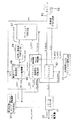
つぎに、上述したノイズ低減回路14の構成の一例について説明する。このノイズ低減回路14は、図23に示すように、入力端子71から入力されたMPEGデコーダ13からの画像データが入力されるブロック歪低減回路72と、ブロック歪低減回路72から画像データが入力されるフィールド巡回型ノイズ低減回路73とを備え、フィールド巡回型ノイズ低減回路73からの出力を出力端子74から上述の画質補正回路15に出力する。
【0198】
ブロック歪低減回路72は、図24に示すように構成されている。この図24に示したブロック歪低減回路72において、クロマ信号入力端子76には、上述のMPEGエンコーダ5でブロック符号化等の圧縮符号化が施された後にMPEGデコーダ13で復号された画像データのクロマ成分が入力され、輝度信号入力端子77には、輝度成分が入力される。
【0199】
HD・VD入力端子78には、水平同期信号及び垂直同期信号が入力され、制御信号発生部79に送られて、各回路で必要なタイミング信号が作成される。
【0200】
輝度信号入力端子77より入力された輝度信号は、補正信号算出部80と、パラメータ算出部81と、エッジ抽出部82と、切換選択スイッチ83と、動き検出部84とに送られる。
【0201】
補正信号算出部80において、上記入力された輝度信号が加算器85及び補正値算出部86に送られている。補正値算出部86では、境界の両隣の画素の隣接差分から補正後の傾きを予測して補正値を求め、また、ブロック歪判定部からの補正強/弱情報に基づいてこれに応じた補正を求め、さらに境界の距離に反比例した各画素毎の補正値を求める。この補正値算出部86からの補正値を加算器85に送って上記入力輝度信号と加算している。
【0202】
また、入力輝度信号は、エッジ抽出部82のHPF(ハイパスフィルタ)87に入力され、エッジ要素の検出の為に2次微分を行なう。本実施の形態では、例えばラプラシアンを用いて、エッジ要素の抽出を行なう。HPF87でエッジ抽出された信号は、最大値抽出部88に入力される。ここでは、次段の2値化部89で必要なしきい値を求める為に、ブロック境界をはさんだエッジ抽出ブロック内において最大値の検出を行なう。
【0203】
2値化部89では、最大値抽出部88で求められたしきい値と、HPF87でエッジ要素抽出された信号が入力され、しきい値をもとに、信号の2値化を行なう。ハフ変換部90では、2値化された信号をもとに、ブロック境界をはさむエッジ抽出ブロック内でハフ変換を行ない、これによりエッジ要素をパラメータ空間(ρ、θ)に写像することにより、ブロック内の直線(ρ0、θ0)を求める。求まったρ0、θ0はブロック歪判定部91へ入力される。
【0204】
また、輝度信号入力端子77からの上記入力輝度信号は、パラメータ演算部81のパラメータ演算回路92へ入力され、ブロック歪判定部91で必要な補正ブロック内のパラメータを求める。
【0205】
また、上記入力輝度信号は、動き検出部84のメモリ93へ入力され、メモリコントローラ94からの制御によって書き込みが行われる。メモリコントローラ94によって、メモリ93から読みだされた前フィールドの輝度信号は、パターンマッチング部95へ入力され、一方で入力された輝度信号とパターンマッチングが行なわれる。このパターンマッチングの演算結果は動きベクトル判定部96へ入力され、動きの大きさを判断できる。ここで、求まった動きの有無はブロック歪判定部91に入力される。
【0206】
ブロック歪判定部91では、エッジ抽出部からのブロック内の直線成分(ρ0、θ0)とパラメータ演算部からの補正ブロック内のパラメータと動き検出部からの動きの大きさを用いて、ブロック歪か否かの判定、ブロック歪補正値を制御して使うか(弱)否か(強)の判定を行ない、この補正強/弱信号を補正信号算出部80の補正値算出回路32へ送り、また補正ON/OFF信号を切換選択スイッチ(セレクタ)83のコントロール端子に送る。
【0207】
また、上記入力輝度信号は、補正信号算出部80の加算器85に入力され、輝度信号と補正値算出部86から求めた補正値を加算することにより、ブロック歪除去された信号が求められ、切換選択スイッチ(セレクタ)83へ送られる。
【0208】
セレクタ83では、ブロック歪判定部91からのブロック歪ON/OFF信号に応じて、入力された輝度信号をそのまま出力するか、補正された信号を出力するかを選択する。
【0209】
一方、入力されたクロマ信号は遅延回路97に入力され、補正回路を通過する輝度信号との遅延を合わせる。
【0210】
なお、セレクタ83を使わずに、ブロック歪判定部91からのブロック歪ON/OFF信号がOFFの場合には補正値算出部85からの出力である補正信号を0にする方法を用いてもよい。
【0211】
なお、この図24のノイズ除去回路72では、輝度信号についてのみブロック歪低減処理を施すことを想定しているが、クロマ信号についても同様の処理を施すことができる。
【0212】
次に、上記図24で示す構成のブロック歪低減回路72におけるブロック歪低減処理のアルゴリズムについて、さらに詳細に説明する。
図25は、本発明の実施の形態となるブロック歪低減方法のアルゴリズムを説明するためのフローチャートを示している。この図25の例では、H(水平)方向についての処理のアルゴリズムを示しているが、V(垂直)方向についてのブロック歪低減アルゴリズムは、H方向の処理がV方向に変わる以外は同様であるため説明を省略する。
【0213】
この図25において、最初のステップST71では、H方向の総てのブロック境界について、ブロック歪低減処理が終了したか否かを判別しており、YESの場合は処理を終了し、NOの場合に次のステップST72に進む。
【0214】
ここで、ブロック歪低減処理のために用いられる画素について、図26を参照しながら説明する。この図26の例では、例えば、ブロック符号化にDCT符号化が用いられ、8×8画素でDCTブロックを構成する場合の処理対象の具体例を示している。すなわち、図中の左右のDCTブロック100L,100Rのブロック境界から左側及び右側にそれぞれ5画素ずつがブロック歪低減処理に用いられ、ブロック境界から4画素ずつが補正範囲とされるとき、エッジ抽出ブロック101はブロック境界を中心とする8×8画素のブロックであり、ブロック歪補正処理ブロック103は、このエッジ抽出ブロック101内の1ライン上の8画素から成るブロックである。上記図26の最初のステップST71では、ブロック歪補正処理が全ての補正処理ブロック102について行われたか否かを判別している。
【0215】
次のステップST72では、ブロック歪か否かの判定に必要とされるパラメータとしての境界差分|tmp0|、アクティビティ|tmp| 及び隣接差分|diff|を、次の計算式により求める。
【0216】
【0217】
次に、ステップST73において、補正処理ブロックに対応する上記エッジ抽出ブロック101内のエッジ抽出を行ない、直線成分(ρ0、θ0)を求める。このエッジ抽出処理の詳細については、後ほど説明する。
【0218】
次に、ステップST74に進んで、補正処理ブロックを挟む上記2つのDCTブロック100L,100Rについて、動きの大きさを調べる。この動き検出動作の詳細については、後ほど説明する。
【0219】
次に、ステップST75aでは、上記各ステップST72,ST73,ST74で求めたパラメータ、直線成分(ρ0、θ0)、及び動きの大きさを用いて、このブロック境界にブロック歪があるかどうかの判定と補正の強さの判定処理を行なう。このブロック歪判定処理の一例については、後ほど説明する。
【0220】
次のステップST75bで、ブロック歪ありとされればステップST76aに進み、ブロック歪無しとされればステップST78に進む。
【0221】
ブロック歪と判定されれば、ステップST76aに進み、画像の性質、特に線形性に基づいて、隣接差分から補正後の境界段差|step|を、
|step|=|diff3+diff4|/2
の式から求める。そして、補正後にこれだけの境界段差|step|を持たせるために必要な補正量|σ|を、
|σ|=(|tmp0|−|step|)/2
により求める。ここで、上記境界差分|tmp0|を所定の閾値corr_th で弁別して補正の強さを切り換えることが好ましく、この場合、|tmp0|<corr_th となって補正の強さを強(補正強)とするとき、補正量|σ|を、
|σ|=(|tmp0|−|step|)/2
とし、|tmp0|≧corr_th となって補正弱のとき、上記補正量|σ|を半分に減らして、
|σ|=(|tmp0|−|step|)/4
の補正を行う。
【0222】
これは、上記境界差分|tmp0|が所定の閾値corr_th より大きい場合は、本当はブロック境界にエッジが存在するのに、ブロック歪判定で誤判定された可能性もあるので、誤補正を回避するために、上記補正の強さを強/弱に切り換えるものである。
【0223】
次のステップST76bでは、得られた補正値|σ|から、各画素毎の補正値を求める。隣の補正範囲とのつなぎ目を滑らかにする為、またブロック歪は境界付近程強く現れることから、次の式に示すように、境界からの距離に反比例した補正値を求める。
【0224】
具体的には、図27の補正範囲102内の各画素b〜iについての各補正値をそれぞれ|σb|〜|σi|とするとき、上記補正値|σ|を用いて、
|σe|=|σ| ,|σf|=|σ|
|σd|=|σ|/2 ,|σg|=|σ|/2
|σc|=|σ|/4 ,|σh|=|σ|/4
|σb|=|σ|/8 ,|σi|=|σ|/8
のような各補正値をそれぞれ求める。
【0225】
次のステップST76cでは、上記ステップST76bで求められた各画素b〜i毎の補正値|σb|〜|σi|を用いて、ブロック歪補正された映像信号(画像データ)SBb〜SBiを求める。
【0226】
具体的には、補正前の各画素b〜iの入力画像データをSb〜Siとするとき、上記tmp0の正負に応じて、補正された画像データSBb〜SBiを、
tmp0≧0:SBb=Sb+|σb| ,tmp0<0:SBb=Sb−|σb|
tmp0≧0:SBc=Sc+|σc| ,tmp0<0:SBc=Sc−|σc|
tmp0≧0:SBd=Sd+|σd| ,tmp0<0:SBd=Sd−|σd|
tmp0≧0:SBe=Se+|σe| ,tmp0<0:SBe=Se−|σe|
tmp0≧0:SBf=Sf−|σf| ,tmp0<0:SBf=Sf+|σf|
tmp0≧0:SBg=Sg−|σg| ,tmp0<0:SBg=Sg+|σg|
tmp0≧0:SBh=Sh−|σh| ,tmp0<0:SBh=Sh+|σh|
tmp0≧0:SBi=Si−|σi| ,tmp0<0:SBi=Si+|σi|
とするような補正を行う。
【0227】
次のステップST77では、このようにブロック歪補正処理された信号を出力する。
【0228】
上記ステップST75bでブロック歪でないと判定されれば、ステップST78に進んで、補正範囲の原信号をそのまま出力する。
【0229】
次に、上記ステップST73におけるエッジ検出処理の動作の一例について、図27を参照しながら説明する。
【0230】
図27の最初のステップST81では、エッジ要素抽出の為、エッジ抽出ブロック内の入力信号に対して、2次元HPF(ハイパスフィルタ)、例えばラプラシアンフィルタをかけている。
【0231】
この2次元のラプラシアンフィルタとしては、例えば図28の係数のようなものが挙げられるが、この図28の例に限定されるものではなく、また例えば、 Sobelオペレータ、 Prewittオペレータ、Kirschオペレータ、Robinsonオペレータ等の種々の変形が考えられる。
【0232】
次に、ステップST82に進んで、上記HPFをかけたブロック内の信号の最大値Maxを検出し、次のステップST83でこの最大値Maxに基づく閾値Thresh(例えばThresh=Max/2)を用いて2値化を行い、エッジ要素を抽出する。すなわちこの2値化は、入力信号Sin>Threshのとき、出力信号Sout =1とし、Sin≦Threshのとき、Sout =0とするような処理である。
【0233】
次に、ステップST84に進んで、抽出されたエッジ要素に、ハフ変換を行ない、パラメータ空間(ρ,θ)に写像する。このハフ変換は、ブロック内のエッジ要素(x,y)をパラメータ空間(ρ,θ)に、
xcosθ+ysinθ=ρ
の式により写像するものである。
【0234】
次のステップST85で、このパラメータ空間で多くの点が集まる(ρ0,θ0)を検出する。この(ρ0,θ0)を通過する直線がエッジ抽出ブロック内で検出された直線エッジということになり、ステップST86でパラメータ(ρ,θ)を出力している。
【0235】
次に、上記図25のステップST74での動き検出処理の動作の一例について、図29を参照しながら説明する。
【0236】
この図29の動き検出処理においては、上記図27における処理する補正処理ブロックのブロック境界を挟む左右のDCTブロック100L,100Rについて、パターンマッチングを行なう。
【0237】
パターンマッチングはDCTブロック内の総ての画素について、同一位置の前フィールドの画素をメモリーから読みだし(ステップST92)、次の式(1)に示す演算式の処理を行い(ステップST93)、メモリに現フィールドの画素を書き込む(ステップST94)。
【0238】
この式(1)において、Sn(i,j)は、nフィールドにおける位置(i,j)の画素の輝度信号を示し、BLK_H,BLK_Vは、それぞれH,V方向のDCTブロックサイズを示している。
【0239】
これらのステップST92〜ST94の処理について、DCT(M×N)ブロック内の全ての画素について、処理が終わったか否かを最初のステップST91で判別し、YESのとき(処理が終了したとき)にはステップST95に進んで、上記式(1)で求めたCrの値に応じて、動き判定を行っている。
【0240】
このステップST95の動き判定としては、上記Crの値に対して所定の閾値mov_thL,mov_thH(ただしmov_thL<mov_thH)を設定し、
Cr<mov_thL のとき、動き小
mov_thL≦Cr<mov_thH のとき、動き中
mov_thH≦Cr のとき、動き大
のような判定を行うことが挙げられる。
【0241】
なお、この図29の例では、パターンマッチングをDCTブロック内の総ての画素について行ったが、この例にのみ限定されるものではなく、例えば、LPFをかけ、2、4画素の間引き処理を行なった後、間引かれた画素についてパターンマッチングを行なう等の変形も考えられる。
【0242】
また、図29の例では、動きの大きさを求める手段として、同一位置のDCTブロックに対するパターンマッチングを用いたが、この例にのみ限定されるものではなく、例えば、動き補償範囲内のすべての試行ベクトルについてパターンマッチングC(k)を比較し、最小のC(k)を与える試行ベクトルを動きベクトルとして動きの有無を求める変形や、代表点マッチングを行なう等の変形も考えられる。
【0243】
次に、上記図25のステップST75a,ST75bにおけるブロック歪判定動作の一例について、図30を参照しながら説明する。
【0244】
この図30に示す例においては、パラメータ判定と動き検出による判定とを組み合わせて用いている。
【0245】
まず、上記図26の補正処理ブロックのブロック境界を挟む左右のDCTブロック100L,100Rについて、上述したようなパターンマッチングを行って、動きの大きさを調べ、ステップST101で、検出された動きが小であるか否かを判別する。両方のDCTブロック100L,100R内の動きが小さいとされれば、量子化誤差は無いと判断し、ステップST106に進んで、ブロック歪補正をかけずに処理を終了する。
【0246】
ステップST101でNO、すなわち動きが小さくないときには、次のステップST102に進んで、直線エッジがブロック境界上に存在するか否かを判別する。このとき、ρ0=エッジ抽出ブロックサイズ/2,θ0=π/2とする。ステップST102で境界上にあると判別されれば、強いブロック歪があるとされ、ステップST108に進んで、ブロック歪(強)の補正をかける。
【0247】
ステップST102でNOと判別されれば、ステップST103に進んで、上記図4の左右のDCTブロック100L,100Rの境界の近傍領域(エリア)内を直線エッジが通過するか否かを判別する。通過すれば、弱いブロック歪があるとして、ステップST107に進んで、ブロック歪(弱)の補正をかける。
【0248】
ステップST83でNOと判別されたときには、パラメータを用いてブロック歪の判定を行って、補正強か(ステップST104)、補正弱か(ステップST105)の判別を行う。補正強と判別されたときにはステップST108に進み、補正弱と判別されたときにはステップST107に進む。それ以外は、補正offとされ、ステップST106に進む。
【0249】
ここで、上記ブロック歪判定の一例を説明すると、上記パラメータ|tmp0|、|tmp| 及び|diff|に基づいて、次のような条件判別を行うことによりブロック歪か否かの判定を行う。この判定条件は、
(1) 周辺と比べて突出した段差であるか否か。
:境界差分|tmp0|>アクティビティ|tmp|
(2) 直流成分及び低周波成分の量子化誤差による段差であるか、すなわち、ブロック歪による段差であるか否か。
:境界差分|tmp0|<閾値div_th
ここで、閾値div_thとしては、本実施の形態では固定値を用いたが、各ブロックの量子化ステップサイズの最大値に比例した値を用いることもできる。
(3) 境界の両隣に境界の段差より大きな段差がないか、すなわち、境界の両隣にエッジがないか否か。
:隣接差分|diff3|≦境界差分|tmp0|
かつ、隣接差分|diff4|≦境界差分|tmp0|
の3つである。
【0250】
これらの3つの判定条件の全てが満たされれば、ブロック歪ありとされる。また、補正の強さは、上記境界差分|tmp0|が所定の閾値corr_th より小さいか否かに応じて決定しており、
|tmp0|<corr_th のとき、補正強
|tmp0|≧corr_th のとき、補正弱
ただし、corr_th<div_th
としている。
【0251】
ここで、上記各閾値div_th,corr_th の値は、上記動き検出処理により得られた動きの大きさによって適応的(アダプティブ)に変化させることが好ましい。例えば、
動き大のとき、div_th =DIV_TH (定数)
corr_th=CORR_TH(定数)
動き中のとき、div_th =DIV_TH/2
corr_th=CORR_TH/2
とすればよい。
【0252】
なお、動き検出処理における動きの大きさは、大/中/小の3段階にのみ限定されるものではなく、上記各閾値div_th,corr_th の値も上記動き大/中の2段階には限定されず、さらに細かい段階に変化させるようにしてもよい。
【0253】
次に、上記図27と共に説明したエッジ抽出処理の方法としては、前述のハフ変換を用いずに、以下に述べるような簡易な方法で行うこともできる。
【0254】
この簡易なエッジ抽出の場合の動作を説明するためのフローチャートを図31に示し、このエッジ抽出を用いる場合のブロック歪低減回路の概略構成のブロック図を図32に示す。
【0255】
この例においては、先ず、図31のステップST111に示すように、エッジ抽出を1次元(水平方向)の2次微分(BPF:バンドパスフィルタ)により行なっている。2次微分特性の伝達関数H(z)としては、例えば、
H(z)=(−1+2z-1−z-2)/4
が挙げられる。
【0256】
2次微分信号の絶対値をとった後、ステップST112では処理ブロック内で最大値の検出を行い、この最大値を用いて次のステップST113でBPF処理画像の2値化を行い、エッジ検出を行なう。2値化する際の閾値は、前述の例と同様に、例えばブロック内で2次微分および絶対値処理して得た最大値の1/2とすればよい。
【0257】
図32のエッジ抽出部82’では、端子77からの輝度信号入力を、BPF87’で上述のように2次微分し、絶対値化回路110で絶対値をとり、最大値検出回路88で最大値を検出している。最大値検出回路88からの閾値2値化回路89に送り、絶対値化回路110からの信号を2値化している。2値化回路89からの出力は、垂直相関検出部111に送られる。
【0258】
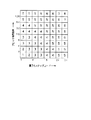
垂直相関検出部111では、このようにして抽出されたエッジ成分のブロック境界における垂直相関の強さを求める。このときの垂直相関の強さを求める方法の一例を図33を用いて説明する。
【0259】
この図33において、注目するブロック境界を含む領域bとその近傍の領域aおよびcに分割する。先に抽出したエッジ成分の数を各領域毎に算出する。これらをEa、Eb、Ecとする。図33において、エッジとして抽出された画素を1と記し、エッジではないと判別された画素を0と記している。本例では、Ea=5、Eb=12、Ec=5となる。
【0260】
ブロック境界を含む領域とそうでない領域におけるエッジ成分の数の比Kvを求め、クラス分けを行なう(図31のステップST114)。
【0261】
例えば、
Kv≧4 の時、 クラス1
2≦Kv<4 の時、 クラス2
1≦Kv<2 の時、 クラス3
Kv<1 の時、 クラス4
とする。図34の例では、
Kv=(2×12)/(5+5)
=2.4
なのでクラス2となる。
【0262】
次に、図32のブロック歪の判定部91’の役割について説明する。各クラスに応じて重み係数Kcを割り当てる。この各クラス毎の重み係数Kcとしては、例えば
【0263】
一方、パラメータ算出部で求めた各パラメータ値から、補正OFF/弱/強の判定を行ない、重み係数Kpを得る。
【0264】
【0265】
よって、ブロック境界部の垂直相関が強い場合には、補正量が大きくなり、ブロック歪の除去が効果的に行うことができる。つまり、ブロック歪の検出精度を高めることになる。
【0266】
なお、図32の他の構成及び動作は、上述した図25の例と同様であるため、対応する部分に同じ指示符号を付して説明を省略する。
【0267】
本例では、クラスおよび補正段階をそれぞれ4および3段階として説明したが、特にこれに限定されず、例えば重み係数Kcを下記の式により求めても良い。
【0268】
Kc=Eb/(Ea+Eb+Ec)
また、相関検出部から得たクラスにより、ブロック歪判定部の検出の閾値であるdiv-thの値を制御してもよい。例えば、垂直相関が弱い程、ブロック歪である可能性が低いので、検出の閾値div_thの値を大きくし、検出しにくい方向へ制御する。
【0269】
なお、本発明の実施の形態におけるエッジ抽出部、補正信号算出部、ブロック歪判定パラメータ算出部等については、上述したようなアルゴリズムを用いたが、これらのアルゴリズムにのみ限定されるものではなく、例えば、補正信号算出部にはLPFを用いたり、エッジ抽出部にはエッジ追跡によるエッジ抽出法などの種々のエッジ抽出法、ブロック歪判定部には種々のパラメータを使うといった種々の変形が考えられる。
【0270】
また、上述した実施の形態は輝度信号の水平方向に対してブロック歪補正をかける例であるが、この例にのみ限定されるものではなく、例えば、垂直方向やクロマ信号にブロック歪補正をかけるといった種々の変形が考えられる。
【0271】
上述のブロック歪低減回路によれば、入力画像データのエッジ成分を抽出し、動きを検出し、ブロック歪判定に必要なパラメータを求め、これらのエッジ抽出結果、動き検出結果、及びパラメータ演算結果に基づいてブロック歪を判定し、この判定結果に応じてブロック歪補正をかけているため、ブロック歪の判定にエッジ成分情報や動き検出情報を用いることによりブロック歪の判定が有効に行え、誤判定を防止できる。従って、ブロック歪の誤判定により生じていた弊害、例えば完全に歪が除去できなかったり、エッジを誤補正して擬似エッジを発生させたりするような問題点を回避することができる。
【0272】
次に、フィールド巡回型ノイズ低減回路73の具体例について、図34を参照しながら説明する。
【0273】
図34の入力端子120には、上記図24のブロック歪低減回路72からの映像信号が入力されている。この入力映像信号Vinが減算器121、122にそれぞれ供給される。減算器121からの出力信号は、出力端子123を介して取り出されると共に、フィールドメモリ124に書き込まれる。フィールドメモリ124と関連して、メモリコントローラ125が設けられている。メモリコントローラ125は、フィールドメモリ124の書き込み動作及び読み出し動作を制御するためのもので、フィールドメモリ124の読出データは、書き込みデータに対して1フィールド遅延されたものである。すなわち、出力信号をVout とし、フィールド遅延をF-1と表すとき、フィールドメモリ124からの出力信号は、Vout・F-1 となり、このフィールド遅延出力信号が減算器124に供給される。減算器122では、入力信号Vinから上記フィールド遅延出力信号Vout・F-1 を減算して出力する。
【0274】
減算器122からの出力信号は、帯域制限用のLPF(ローパスフィルタ)126を介し、非線形回路127に送られる。非線形回路127は、入力信号であるLPF126からの出力のレベルに応じて帰還係数Kを乗じるもので、例えばROMにより構成される。この非線形回路127は、小さい範囲のフィールド差分をノイズ成分として出力し、大きいフィールド差分は、動きにより発生したものとして、出力を0とするような入出力特性を有している。すなわち、ノイズ成分はフィールド間の相関が小さくかつ小振幅である、という特性を利用して、非線形回路127がノイズ成分を抽出する。
【0275】
この非線形回路127からの出力信号K・(Vin−Vout・F-1) が減算器121に供給され、入力映像信号Vinから減算される。これは、減算器121において抽出されたノイズ成分を入力映像信号Vinから減算することによって、ノイズの低減された出力映像信号Vout を得ることに相当する。
【0276】
ここで、
Vout = Vin−K・(Vin−Vout・F-1)
Vout・(1−K・F-1) = Vin・(1−K)
より、出力映像信号Vout は、
Vout = Vin・(1−K)/(1−K・F-1)
となる。
【0277】
次に、図1の画質補正回路15の具体例としての輪郭強調回路について、図35を参照しながら説明する。
【0278】
図35は、画質補正回路15となる輪郭強調回路の構成例を示している。この図35において、入力端子130には、図1のノイズ低減回路14からの画像データ、より具体的には図34のフィールド巡回型ノイズ低減回路73から出力端子74を介して得られた画像データが供給される。入力端子130からの入力信号は、BPF(バンドパスフィルタ)131及び加算器132に供給される。BPF131では、画像の輪郭成分などの中高周波数成分が抽出される。この抽出された輪郭成分などは、コアリング回路133に送られて、小振幅信号であるノイズ成分などを除去するような非線形処理(コアリング処理)が施された後、利得制御(ゲインコントロール)回路134に送られて、補正量の制御がなされ、補正信号として加算器132に送られる。
【0279】
また、端子135には、上記図1のマイクロコンピュータなどを制御回路19からの制御信号が供給されており、この制御信号はコアリング回路133及び利得制御回路134に送られている。すなわち、図1の操作入力部20には、輪郭強調の制御スイッチなども設けられており、このスイッチなどを操作することにより輪郭強調の効果の程度を制御できるようになっている。
【0280】
このようにして、輪郭強調回路において映像信号の中高周波数成分が強調され、画像の精細度を上げている。
【0281】
以上説明した画質補正回路15によれば、ブロックDCT符号化等を用いて画像圧縮/伸張した際に発生するブロック歪などのノイズを先に除去しているため、この後に輪郭強調等の画質補正を効果的に行うことができる。
【0282】
また、画質補正回路15では、輪郭強調回路などの後処理において、重み付けした符号化情報を用いて適応的処理を施しても良い。
【0283】
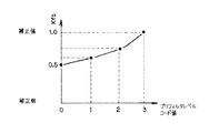
すなわち、ブロック歪判定の誤判定による破綻を軽減するために、ブロック歪の補正量を例えばブロック境界の段差の大きさに応じて制御することが考えられる。この場合、ブロック境界の段差が大きいとき、補正量は小さくなり、ブロック境界の段差は若干残ることになる。そこで、このような残留ブロック歪を強調しないように、重み付けした符号化情報を用いて輪郭強調の適応的処理を行う。図36は、このような変形例における輪郭強調回路の構成を示すブロック図である。この図36の利得制御回路134において、上記図1の制御回路19から端子135を介して供給される制御信号に対して、例えば端子136からの符号化情報として量子化ステップの値、端子137からの復号画像情報としてブロック境界の段差の値及びブロック境界からの距離により、ウェイティング(重み付け)回路138bで重み付けを行う。利得制御回路134に供給するパラメータとしてのゲイン(利得)値Gは、上記図1の制御回路19におけるゲイン(利得)設定値をGst、量子化ステップ重み付け係数をKQ 、境界距離の重み付け係数をLW とするとき、例えば次の式により求める。
G = Gst×(KQ/8)×(LW/4)
この式中の1/8,1/4は、正規化のための除数である。
【0284】
ここで、図37は量子化ステップコード及びブロック境界段差に対する量子化ステップ重み付け係数を示し、図38はブロック境界距離に対する境界距離重み付け係数を示している。
【0285】
具体例を挙げて説明する。端子135からの制御信号としてのゲイン設定値が2のとき、量子化ステップコード及びブロック境界段差が与えられて図37のテーブルより量子化ステップ重み付け係数が例えば4となり、ブロック境界からの距離1が図38のテーブルに与えられて境界距離重み付け係数値2を得たとする。このときの利得制御回路134に供給されるパラメータ、すなわちゲインGは、
G = 2 ×(4/8)×(2/4) = 0.5
となり、輪郭強調効果は弱まる。
【0286】
これは、コアリング回路133に関しても同様である。
すなわち、図36のコアリング回路133において、端子135から供給される制御信号としてのパラメータに対して、例えば端子136からの符号化情報としての量子化ステップの値、端子137からの復号画像情報としてのブロック境界の段差の値及びブロック境界からの距離により、ウェイティング(重み付け)回路138aで重み付けを行う。
【0287】
図39は量子化ステップコード及びブロック境界段差に対するコアリング重み付け係数を示している。コアリング回路133に供給するパラメータの値Cは、上記図1の制御回路19におけるコアリング設定値をCst、重み付け係数をKC 、境界距離の重み付け係数をLW とするとき、例えば次の式により求める。
C = Cst×KC×(LW/4)
この式中の1/4は、正規化のための除数である。
【0288】
ところで、上述した図36〜図39の特性は一例であって、これらに限定されるものではない。また、上述したMPEG規格で圧縮/伸張される場合、量子化ステップはマクロブロック単位で変化する。このため、注目するブロック境界において、隣接するマクロブロックの量子化ステップの差分を加味してもよい。
【0289】
なお、画質補正回路15は、上述した一例に限定されるものではなく、例えば、上記実施の形態においては、水平(H)方向の処理について述べたが、垂直(V)方向についても同様に適用可能である。また、輝度信号の処理のみならず、色信号についても同様に適用可能であることは勿論である。
【0290】
したがって、この輪郭補正回路を含む画質補正回路15では、圧縮符号化された映像信号を復号して信号処理する際に、復号された映像信号のノイズを低減した後、ノイズ低減された映像信号に対して画質補正を行っているため、輪郭強調等の画質補正を効果的に行うことができる。
【0291】
具体的には、ブロックDCT符号化等の画像圧縮/伸張に伴って発生するブロック歪やモスキートノイズ等の量子化歪やノイズを低減、除去した後に、輪郭強調等の画質補正を行うことにより、効果的なブロック歪やモスキートノイズの除去と輪郭強調等の画質補正を行うことができる。
【0292】
また、上記ノイズ低減の際に、映像信号の画面内におけるノイズを低減し、次に画面間で発生するノイズを低減することにより、画面内で発生する歪やノイズと、画面間で発生する歪やノイズとを効果的に除去することができる。
【0293】
なお、上述の光ディスク記録再生装置1において、MPEGエンコーダ5では、プリフィルタのオン/オフを含む強さをシーケンス毎、GOP毎、ピクチャ毎、スライス毎、或いはマクロブロック毎にコード化し、例えば画像データのヘッダにデータとして付加して光ディスクDに記録しても良い。また、このプリフィルタの強さを示すデータを伝送路を介してノイズ低減回路14に伝送しても良い。
【0294】
このように、光ディスク記録再生装置1において、スライス毎にプリフィルタの強さを示すデータを画像データに付加するときの一例について図2に示すMPEGエンコーダ5を用いて説明する。
【0295】
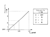
スライス毎にプリフィルタ23の強さを示すデータを生成するときには、スライス毎におけるフィルタ係数k_currentの各スライス毎における代表値を決定することで生成する。この各スライス毎における代表値を決定するときには、図40に示すように、例えば4段階にコード化することで決定する。この図40によれば、フィルタ係数k_currentの大きさに応じてプリフィルタレベル(プリフィルタの強さ)のコード値を決定する。すなわち、このプリフィルタレベルは、例えばフィルタをオフ状態としている場合を0とし、弱,中,強である場合をそれぞれ1,2,3としてコード値を決定して、コード化を行う。
【0296】
この代表値は、例えば各スライス内における小ブロックの平均値とする。そして、このコード化されたプリフィルタ23の強さが他の種々の付加情報とともに画像データのヘッダとして付加される。そして、このプリフィルタ23の強さを示すプリフィルタレベルは、例えば動画像符号化回路24で画像データに付加されて光ディスクDに記録される。そして、このプリフィルタレベルは、MPEGデコーダ13を介してノイズ低減回路14及び画質補正回路15に供給される。
【0297】
また、このフィルタの強さを示すプリフィルタレベルは、符号化情報として、例えばプリフィルタ23からノイズ低減回路14及び/又は画質補正回路15に伝送路を介して入力されても良い。
【0298】
このプリフィルタの強さを示すデータをノイズ低減回路14で用いる一例について説明する。
【0299】
上述のブロック歪低減回路72でプリフィルタレベルを用いる場合には、例えばMPEGエンコーダ5からのコード値に応じた係数Kfbを用いて、上述の重み係数Kcを変化させる。すなわち、このブロック歪低減回路72では、プリフィルタレベルに応じてブロック歪の補正の重み付け係数Kcfを下記のように定める。
【0300】
Kcf=Kc×Kfb
ここで、Kfbは、プリフィルタレベルに応じて図41に示すように割り当てる。
【0301】
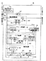
また、フィールド巡回型ノイズ低減回路においては、図42に示すように構成しても良い。すなわち、この図42に示したフィールド巡回型ノイズ低減回路73は、減算器121,減算器122と、周波数帯域を制限するLPF140a,BPF140b,BPF140cと、非線形回路141a〜141cとフィールドメモリ124と、メモリコントローラ125とで構成されている。なお、以下の説明においては、上述のフィールド巡回型ノイズ低減回路と同一の部分は同一の符号を付することでその詳細な説明を省略する。
【0302】
このフィールド巡回型ノイズ低減回路73では、LPF140a,BPF140b,BPF140cを設けることで、周波数帯域毎に帰還量を制御する。すなわち、このフィールド巡回型ノイズ低減回路73では、端子142からプリフィルタレベルが非線形回路141a〜141cに供給され、MPEGエンコーダ5からのプリフィルタレベルに応じて帰還量を変化させる。ここで、非線形回路141a〜141cでは、供給されるプリフィルタレベルに応じて入出力特性を変化させる。
【0303】
このフィールド巡回型ノイズ低減回路73では、例えば、プリフィルタレベルが強いときには高い周波数帯域の帰還量を大きくするように制御する。これにより、このフィールド巡回型ノイズ低減回路73では、フィールド差分信号の高い周波数帯域の小振幅のノイズを低減することができる。なお、このフィールド巡回型ノイズ低減回路73では、各周波数帯域毎の境界で急激に帰還量が変化しないように、なだらかにソフトスイッチングを行うことが望ましい。
【0304】
そして、各非線形回路141a〜141cを通過した画像データは、加算器143で加算処理されて、減算器121に供給される。
【0305】
これにより、上述のMPEGエンコーダ5でプリフィルタが施された部分について復号を施した後に生ずる高周波成分を効率的に除去することができる。したがって、このフィールド巡回型ノイズ低減回路では、プリフィルタレベルの強さを示すデータを用いることで、MPEGエンコーダ5で符号化を行って、復号した後の画像データに生ずるブロック歪やモスキートノイズを除去することができる。
【0306】
つぎに、プリフィルタレベルを図36で示す画質補正回路15で用いる一例について説明する。
【0307】
この画質補正回路15では、ウェイティング回路138a,138bで生成する重み付け係数を変化させる。すなわち、この画質補正回路15では、利得制御回路134のゲインにプリフィルタレベルに応じた係数Kfsを乗算し、コアリング回路133のコアリング設定値にプリフィルタレベルに応じた係数Kfcを乗算する。すなわち、コアリング回路ではコアリング設定値をCst’=Cst×Kfsとし、利得制御回路134では、ゲインをG’=G×Kfcとする。このプリフィルタレベルに応じた重み付け係数Kfs,Kfcは、図43(a)及び図43(b)に示すように、プリフィルタレベルに応じて変化させる。なお、上述のフィールド巡回型ノイズ低減回路73と同様に、周波数帯域によって急激にゲイン、コアリング設定値が変化しないように、周波数的になだらかにスイッチングすることが望ましい。
【0308】
したがって、このような画質補正回路15によれば、符号化して復号した後に生じた高周波成分に応じて画質の補正を行うことができ、効率的に画質の補正を行うことができる。
【0309】
【発明の効果】
以上詳細に説明したように、本発明では、入力画像に圧縮符号化処理及び復号処理を施す画像信号処理装置において、入力画像にフィルタリング処理を施すフィルタ手段と、上記フィルタ手段が行うフィルタリング処理のフィルタレベルを検出するフィルタレベル検出手段と、上記フィルタ手段でフィルタリング処理が施された画像にブロック符号化処理を施す圧縮符号化手段と、上記圧縮符号化手段で圧縮符号化された画像に復号処理を施す復号手段と、上記フィルタレベルに応じて上記復号手段で復号処理が施された画像のブロック歪を少なくとも低減する処理を行うノイズ低減手段とを備え、上記フィルタレベル検出手段は、検出したフィルタレベルを上記ノイズ低減手段に供給し、上記フィルタレベルが強いときには高い周波数帯域の帰還量を大きくして、上記ノイズ低減手段により高い周波数帯域の小振幅のノイズを低減するので、入力された画像に対して圧縮符号化手段を通過させる前にフィルタ手段でフィルタリング処理を行い、復号手段で復号された画像のブロック歪をノイズ低減手段で低減する処理を行うことができる。したがって、この画像信号処理装置では、フィルタリング処理を行うことで符号化効率を向上させることができ、さらに復号後に生ずるブロック歪やモスキートノイズを低減することができる。
【0310】
したがって、このような画像信号処理装置では、フィルタリング処理を行うことにより、入力した画像の高周波成分を減少させることにより、復号後に生ずるブロック歪等を顕著にし、当該ブロック歪等の検出制度を向上させることができる。したがって、この画像信号処理装置では、復号後において効率的にノイズ低減手段によりノイズを低減させることができる。
【0313】
また、本発明では、入力画像に圧縮符号化処理及び復号処理を施す画像信号処理方法において、入力画像にフィルタリング処理を施し、上記フィルタリング処理におけるフィルタレベルを検出し、上記フィルタリング処理が施された画像にブロック符号化処理を施し、上記ブロック符号化処理が施された画像に復号処理を施し、上記復号処理が施された画像のブロック歪を少なくとも低減するノイズ低減処理を行い、上記ノイズ低減処理では、検出した上記フィルタリング処理におけるフィルタレベルが強いときには高い周波数帯域の帰還量を大きくして、高い周波数帯域の小振幅のノイズを低減するノイズ低減処理を行うので、入力された画像に対して圧縮符号化を行う前にフィルタリング処理を行い、復号された画像のブロック歪を低減するノイズ低減処理を行うことができる。したがって、この画像信号処理方法では、フィルタリング処理を行うことで符号化効率を向上させることができ、さらに復号後に生ずるブロック歪やモスキートノイズを低減することができる。
【0314】
したがって、このような画像信号処理方法では、フィルタリング処理を行うことにより、入力した画像の高周波成分を減少させ、復号後に生ずるブロック歪等を顕著にし、当該ブロック歪等の検出精度を向上させることができる。したがって、この画像処理方法では、復号後において効率的にノイズを低減させることができる。
【図面の簡単な説明】
【図1】本実施の形態にかかる光ディスク記録再生装置の一例を示すブロック図である。
【図2】プリフィルタを含むMPEGエンコーダの一例を示すブロック図である。
【図3】フれーむと小ブロックの関係を示す図である。
【図4】プリフィルタ制御方法の一例を示すフローチャートである。
【図5】符号化難易度の平均値d_aveとプリフィルタ係数の代表値k_gopの対応関係を示す図である。
【図6】現在の小ブロックのフレーム間予測で参照される小ブロックで使われたプリフィルタ特性を考慮して、プリフィルタ係数を計算する一例を示す図である。
【図7】符号化難易度d_currentとローパスプリフィルタ係数k_currentとの対応関係を示す図である。
【図8】プリフィルタ係数k_currentの計算方法の一例を示すフローチャートである。
【図9】ローパスプリフィルタ係数k_currentの計算例を示す図である。
【図10】動画像符号化装置内の動画像符号化回路の構成例を示すブロック回路図である。
【図11】動画像符号化装置内の符号化難易度測定回路の構成例を示すブロック回路図である。
【図12】動画像符号化装置の第2の構成例を示すブロック回路図である。
【図13】MPEG方式の予測構造及び各ピクチャタイプの構成を示す図である。
【図14】動画像符号化装置の第3の構成例を示すブロック回路図である。
【図15】MPEG方式における表示順序と符号化順序を示す図である。
【図16】フィルタ特性画像と非フィルタ特性画像のフレームと小ブロックの関係を示す図である。
【図17】プリフィルタ制御方法の一例を示すフローチャートである。
【図18】非フィルタ特性画像において、現在の小ブロックのフレーム間予測で参照される小ブロックで使われたプリフィルタ特性を用いて内挿補間により、プリフィルタ係数を計算する一例を示す図である。
【図19】プリフィルタ係数k_current の計算方法の一例を示すフローチャートである。
【図20】非フィルタ特性画像のローパスプリフィルタ係数k_current の計算例を示す図である。
【図21】プリフィルタの構成例を示す図である。
【図22】動画像符号化装置の第4の構成例を示すブロック回路図である。
【図23】ノイズ低減回路の構成例を示すブロック図である。
【図24】本発明に係る実施の形態となる画像データのブロック歪低減装置の概略構成を示すブロック図である。
【図25】ブロック歪低減方法の処理手順を説明するためのフローチャートである。
【図26】ブロック歪補正のためのブロック境界近傍の画素を示す図である。
【図27】エッジ抽出処理の動作の一例を説明するためのフローチャートである。
【図28】ラプラシアンフィルタの係数の一例を示す図である。
【図29】動き検出処理の動作の一例を説明するためのフローチャートである。
【図30】ブロック歪判定処理の動作の一例を説明するためのフローチャートである。
【図31】1次元の2次微分によりエッジ抽出を行う場合の処理動作の一例を説明するためのフローチャートである。
【図32】図31のエッジ抽出を行う場合の画像データのブロック歪低減装置の概略構成を示すブロック図である。
【図33】垂直相関の強さを求める方法を説明するためのDCTブロック境界近傍の画素を示す図である。
【図34】フィールド巡回型ノイズ低減回路の一例を示すブロック図である。
【図35】画質補正手段としての輪郭強調回路の一例の概略構成を示すブロック図である。
【図36】輪郭強調回路の他の具体例を示すブロック図である。
【図37】量子化ステップコード及びブロック境界段差に対する量子化ステップ重み付け係数の具体例を示す図である。
【図38】ブロック境界距離に対する境界距離重み付け係数の具体例を示す図である。
【図39】量子化ステップコード及びブロック境界段差に対するコアリング重み付け係数の具体例を示す図である。
【図40】プリフィルタレベルと、フィルタ係数k_currentとの関係を示す図である。
【図41】コード値に応じた係数Kfbとプリフィルタレベルとの関係を示す図である。
【図42】フィールド巡回型ノイズ低減回路の他の一例を示すブロック図である。
【図43】(a)が重み付け係数Kfsとプリフィルタレベルとの関係を示す図であり、(b)が重み付け係数Kfcとプリフィルタレベルとの関係を示す図である。
【図44】従来のノイズ低減回路の一例を示すブロック図である。
【図45】プリローパスフィルタの係数を示す図である。
【図46】プリフィルタ係数と符号化難易度との関係を示す図である。
【符号の説明】
1 光ディスク記録再生装置、5 MPEGエンコーダ、13 MPEGデコーダ、14 ノイズ低減回路、15 画質補正回路、19 制御回路、20 操作入力部、22,61 フレームメモリ群、23,62 プリフィルタ、24,63 動画像符号化回路、25,44,66 動きベクトル検出回路、26,65プリフィルタ制御情報記憶回路、27,46 符号化難易度測定回路、28 プリフィルタ制御回路、45 画像処理タイプ判定回路、47,69 符号化難易度平滑化回路、48,70 内挿補間回路、52 ローパスフィルタ、72 ブロック歪低減回路、73 フィールド巡回型ノイズ低減回路[0001]
BACKGROUND OF THE INVENTION
The present invention records and reproduces a moving image signal and a still image signal on a recording medium such as an optical disk and a magnetic tape, and transfers a moving image signal and a still image signal to a video conference system, a videophone system, a broadcasting device, etc. The present invention relates to an image signal processing apparatus and an image signal processing method that are suitable for use when transmitting from a transmission side to a reception side via a network.
[0002]
[Prior art]
Conventionally, block coding such as block DCT (discrete cosine transform) coding is known as a coding method for efficiently compressing and coding still image data, moving image data, and the like.
[0003]
Thus, ringing noise (mosquito noise) and block distortion may occur during compression / decompression of image data or the like by encoding, and noise is more likely to be generated as the compression ratio increases. Further, this noise is more likely to occur as the input image data becomes more complex. As a result, the image indicated by the compressed / expanded image data is disadvantageously deteriorated by noise.
[0004]
In order to reduce image degradation due to noise of image data generated during such compression / decompression, conventionally, a prefilter such as an LPF (low-pass filter) is used to indicate an input image before encoding. Filtering processing is often performed on image data.
[0005]
FIG. 44 shows an example of a conventional video signal encoding apparatus using the prefilter.
[0006]
In the encoding apparatus shown in FIG. 44, the digital moving image signal input from the
[0007]
The
[0008]
On the other hand, the output signal S215 is inversely quantized by the
[0009]
In general, in the
[0010]
Therefore, in the encoding apparatus shown in FIG. 44, considering that the size of the inter-frame difference signal of the input image affects the generated code amount of the inter-frame prediction encoding, the inter-frame difference signal of the input image Depending on the size, the low pass band of the prefilter for the input image is limited. Thereby, the energy of the prediction error signal is attenuated and rough quantization can be prevented, so that the subjective image quality can be improved.
[0011]
Next, a variable prefilter control method in this encoding apparatus will be described.
[0012]
The
[0013]
In addition, after decoding, mosquito noise and block distortion can be reduced by using a block-level macro characteristic and a pixel-level micro characteristic based on local image statistics and coding information. Some employ a method of performing prediction and removing noise components by adaptive filtering.
[0014]
Further, as a technique for reducing block distortion or mosquito noise, there is a technique for performing post-filter processing for filtering the decoded image signal when the image signal is decoded and output, in addition to the above-described technique.
[0015]
[Problems to be solved by the invention]
By the way, although mosquito noise can be suppressed by the pre-filter processing before encoding described above, not only block distortion can be effectively removed, but also high-frequency components are reduced by pre-filter processing, particularly in the case of a picture with intense motion. When decoding processing is performed on an image that has been subjected to prefilter processing, there is a problem that only block distortion is noticeable.
[0016]
On the other hand, the post-filter process after the latter decoding process does not perform the process on the encoding side, so there is no change in the encoding efficiency after the encoding, and the input image is particularly difficult to predict the motion because of its intense motion. On the other hand, there is a problem that the improvement effect cannot be obtained because the quantization becomes coarse throughout.
[0017]
That is, the conventional image encoding / decoding device has a drawback that pre-filter processing before encoding and post-filter processing after decoding are performed independently, and effective noise removal cannot be performed.
[0018]
Therefore, the present invention has been proposed in view of the above-described circumstances, and is an image that suppresses mosquito noise and block distortion that occur when an input moving image or still image is encoded or decoded. An object of the present invention is to provide a signal processing device and an image signal processing method.
[0019]
[Means for Solving the Problems]
The present invention relates to an image signal processing apparatus that performs compression encoding processing and decoding processing on an input image, and filter means that performs filtering processing on the input image, and filter level detection means that detects a filter level of the filtering processing performed by the filter means. Compression coding means for performing block coding processing on the image subjected to filtering processing by the filter means, decoding means for performing decoding processing on the image compression coded by the compression coding means, and the filter level And a noise reduction unit that performs a process of at least reducing block distortion of the image subjected to the decoding process by the decoding unit, and the filter level detection unit supplies the detected filter level to the noise reduction unit. When the filter level is strong, the feedback amount in the high frequency band Enlarge The noise reduction means reduces small amplitude noise in a high frequency band.
[0020]
According to such an image signal processing apparatus, the filtering process is performed by the filter unit before the input image is passed through the compression encoding unit, and the block distortion of the image decoded by the decoding unit is reduced by the noise reduction unit. Process to reduce.
[0021]
The present invention also provides an image signal processing method for performing compression encoding processing and decoding processing on an input image, filtering the input image, detecting a filter level in the filtering processing, and performing the filtering processing on the image Was subjected to block coding processing and the above block coding processing was performed. Decrypt the image, Noise reduction processing that at least reduces block distortion of the image subjected to the decoding processing In the noise reduction process, when the detected filter level in the filtering process is strong, the feedback amount in the high frequency band is increased, and the noise reduction process is performed to reduce small amplitude noise in the high frequency band. It is characterized by that.
[0022]
According to such an image signal method, filtering processing is performed before compressing and encoding an input image, and processing for reducing block distortion of the image is performed after decoding.
[0023]
DETAILED DESCRIPTION OF THE INVENTION
Hereinafter, embodiments of the present invention will be described with reference to the drawings.
[0024]
The image signal processing apparatus and the image signal processing method according to the present invention are applied to the optical disc recording / reproducing
[0025]
The recording system of the optical disk recording / reproducing
[0026]
The A /
[0027]
The
[0028]
The
[0029]
Further, the
[0030]
The
[0031]
The 8-14
[0032]
The
[0033]
The recording system of the optical disc recording / reproducing
[0034]
The reproduction system of the optical disc recording / reproducing
[0035]
The
[0036]
The 8-14 demodulation circuit 11 performs 8-14 demodulation processing on the image data from the
[0037]
The ECC decoder 12 performs error correction processing added by the
[0038]
The MPEG decoder 13 performs a decoding process on the MPEG image data from the ECC decoder 12. The MPEG decoder 13 outputs the decoded image data to the
[0039]
The
[0040]
The image
[0041]
The
[0042]
The D / A conversion circuit 17 performs D / A conversion processing on the NTSC image data from the
[0043]
Further, the reproduction system of the optical disc recording / reproducing
[0044]
The control circuit 19 is composed of, for example, a microcomputer and supplies a control signal to the
[0045]
The
[0046]
Next, an example of the configuration of the
[0047]
In the
[0048]
Using the image data S23 stored in the
[0049]
Ef = Σ | Aij−Fij | (i = 0-15, j = 0-15) (1)
The motion
[0050]
The image data S23 and the motion vector signal MV are input to the encoding
[0051]
Next, to the
[0052]
The prefilter control
[0053]
When the encoding difficulty d and the filter coefficient k_ref are input, the
[0054]
The characteristic of the pre-filter 23 is not limited to the low-pass filter having the characteristic shown in FIG. 46, and may be a low-pass filter having other characteristics.
[0055]
The filter coefficient k_current calculated by the
[0056]
An example of a method for calculating the filter coefficient k_current will be described below. Here, as shown in FIG. 3, a group for every N frames (N ≧ 1) is formed in the input moving image input order, and this group is set as one unit of processing. Hereinafter, the control of the prefilter coefficient will be described with reference to the flowchart of FIG.
[0057]
In the flowchart shown in FIG. 4, first, in step ST11, filter control is started between N frames including the current encoding target frame.
[0058]
In step ST12, the average value d_ave of the encoding difficulty level between the N frames is calculated, and in the next step ST13, the representative value k_gop of the prefilter coefficient between the N frames is calculated. As for the representative value k_gop of the prefilter coefficient, the correspondence to the representative (average) prefilter coefficient is empirically determined in advance with respect to the average value d_ave of the encoding difficulty between N frames. . Here, as shown in FIG. 46, as the degree of encoding difficulty increases, a low-pass filter characteristic with a narrower pass band is associated (that is, k_gop becomes smaller). The correspondence relationship between the average value d_ave of the encoding difficulty level and the representative value k_gop of the prefilter coefficient is, for example, as shown in FIG.
[0059]
Next, in step ST14, control of the filter within one frame is started.
[0060]
First, in step ST15, the encoding difficulty level d (hereinafter referred to as d_current) of the current small block to be encoded is read. In step ST16, the current small block is referred to in inter-frame prediction as shown in FIG. Read the low-pass prefilter coefficient k_ref used in the small block.
[0061]
Next, in step ST17, a low pass pre-filter coefficient k_current used in the current small block is calculated from the encoding difficulty d_current and the low pass pre-filter coefficient k_ref.
[0062]
A calculation example of the low-pass prefilter coefficient k_current is shown in FIG. In the calculation example shown in FIG. 6, first, k_current is statistically calculated from the d_current and k_gop as shown in the equation (a). Here, if the d_current is larger than the d_ave, the k_current is On the contrary, if the d_current is smaller than the d_ave, the k_current becomes larger than the k_gop (that is, the low-pass filter characteristic having a wide pass band). ). The correspondence relationship between the encoding difficulty d_current and the low-pass prefilter coefficient k_current is, for example, as shown in FIG. In the calculation example shown in FIG. 6, next, as in condition (b) and condition (c), the low-pass prefilter coefficient k_current and the low-pass used in the small block that the current small block refers to in inter-frame prediction are used. The prefilter coefficient k_ref is compared. When changes in k_current and k_ref are larger than a predetermined threshold, control is performed to suppress the changes. Specifically, in the calculation example shown in FIG. 6, when k_current is larger than A times (A> 1) of k_ref as in condition (b), k_current is changed to k times ref of A times. When k_current is smaller than B_times (B <1) of k_ref as in condition (c), k_current is changed to B_k_ref. As described above, the low-pass prefilter coefficient k_current used in the current small block is calculated.
[0063]
Returning to the flowchart of FIG. 4, in step ST18 following step ST17 described above, it is determined whether or not the current small block is the last block in the frame. If it is determined in step ST18 that the current small block is not the last block in the frame, the process returns to step ST15. On the other hand, if it is determined in step ST18 that the current small block is the last block in the frame, the process proceeds to step ST19.
[0064]
In step ST19, it is determined whether or not the current frame is the last frame of a group consisting of N frames. If it is determined in step ST19 that the current frame is not the last frame of the group consisting of N frames, the process returns to step ST14, while the current frame is determined to be the last frame of the group consisting of N frames. If so, the process proceeds to step ST20.
[0065]
In step ST49, the control of the filter in the group consisting of N frames is finished.
[0066]
As described above, the
[0067]
Note that in steps ST16 and ST17 in the flowchart of FIG. 4, instead of using the filter coefficient k_ref, the encoding difficulty d_ref of the small block that the current small block refers to in inter-frame prediction may be used.
[0068]
An example of a method for calculating the prefilter coefficient k_current in this case will be described with reference to the flowchart shown in FIG. The difference between the flowchart of FIG. 8 and the flowchart of FIG. 4 described above is step ST26 and step ST27, which correspond to step ST16 and step ST17 in FIG. 4, respectively. Note that steps ST21 to ST25 in FIG. 8 are the same as steps ST11 to ST15 in FIG. 4, and steps ST28 and after in FIG. 8 are the same as steps ST18 and after in FIG. A description of the steps is omitted.
[0069]
In the flowchart of FIG. 8, in step ST26, as shown in FIG. 3, the encoding difficulty level d_ref of the small block that the current small block refers to in inter-frame prediction is read.
[0070]
Next, in step ST27, a low-pass prefilter coefficient k_current used in the current small block is calculated from the encoding difficulty level d_current of the current small block to be encoded and the encoding difficulty level d_ref.
[0071]
FIG. 9 shows a calculation example of the low-pass prefilter coefficient k_current. In the calculation example shown in FIG. 9, as in the conditions (d) and (e), the encoding difficulty level d_current of the current small block to be encoded and the small small block that the current small block refers to in inter-frame prediction. The encoding difficulty level d_ref used in the block is compared. When changes in d_current and d_ref are larger than a predetermined threshold, control is performed to suppress the changes. Specifically, as in the condition (d), when the d_current is larger than C times (C> 1) of the d_ref, the d_current is changed to d times the C_d_ref. Further, as in the condition (e), when the d_current is smaller than D times the D_ref (D <1), the d_current is changed to d times the D_ref. As described above, the encoding difficulty level d_current used in the current small block is checked. Next, k_current is statistically calculated from the above d_current and k_gop as shown in equation (f) in FIG.
[0072]
In the case of the flowchart of FIG. 9 described above, the pre-filter control
[0073]
At this time, as described above, when the encoding difficulty level d_ref is read, only the block address mb_address is used, and the small block at the position of the same block address mb_address on the frame referred to in inter-frame prediction is used. A parameter that specifies the passband limit of the used low-pass prefilter may be read as the filter coefficient d_ref. In this case, it is not necessary to input the motion vector signal MV to the prefilter control
[0074]
Returning to FIG. 2, the pre-filter 23 performs low-pass filter processing specified by the pre-filter coefficient k_current on the current small block, and outputs a processed image signal S22.
[0075]
The processed image signal S22 and its motion vector signal MV are input to the moving
[0076]
FIG. 10 shows a configuration example of the moving
[0077]
In FIG. 10, a motion vector signal MV input from the motion
[0078]
The motion compensation interframe /
[0079]
The
[0080]
Next, the prediction residual signal S66 (original signal when no prediction is performed) is sent to the
[0081]
On the other hand, in the
[0082]
Further, the
[0083]
Next, FIG. 11 shows a configuration example of the encoding difficulty
[0084]
In the moving
[0085]
That is, in the moving
[0086]
Specifically, as a first step, considering a visual characteristic, a low-pass filter having a relatively narrow passband is selected in a portion having a fast local motion or a complicated pattern and a high degree of difficulty in encoding. On the other hand, a low-pass filter having a relatively wide pass band is selected for a portion having a slow motion, a flat pattern, and a low encoding difficulty. Next, as a second step, the pre-filter control information used in the small block that the current small block to be coded refers to in the inter-frame prediction is taken into consideration so that the inter-frame predictive coding efficiency does not decrease. The filter characteristic selected in one stage is modified to finally determine the prefilter characteristic for the current small block to be encoded. As a result, the low-pass prefiltered moving image has a good subjective impression of the encoded image quality and a high encoding efficiency.
[0087]
Next, FIG. 12 shows a moving picture coding apparatus of the second configuration example of the
[0088]
In the second configuration example shown in FIG. 12, the major difference from the moving
[0089]
In FIG. 12, the digital moving image signal S100 input from the
[0090]
The
[0091]
When the encoding difficulty level d and the filter coefficient k_ref are input, the
[0092]
The characteristics of the pre-filter 23 are not limited to the low-pass filter having the characteristics shown in FIG. 45, and may be a low-pass filter having other characteristics.
[0093]
The filter coefficient k_current calculated by the
[0094]
An example of a method for calculating the filter coefficient k_current is the same as the method described with reference to FIG. 6 in the first configuration example.
[0095]
The
[0096]
The processed image signal S102 and its motion vector signal MV are input to the moving
[0097]
In the moving image encoding apparatus having such a configuration, the prediction residual output from the motion
[0098]
Note that the prefilter control method and apparatus in moving picture coding disclosed in Japanese Patent Laid-Open No. 6-225276 also performs prefilter processing on an input image signal. The pre-filter coefficient is not changed within one screen and is constant within the screen, and the filter coefficient is constant for each of a plurality of frames.
[0099]
On the other hand, in the moving image coding circuits of the first configuration example and the second configuration example as described above, the filter characteristics at the time of the pre-filter processing for the moving image signal subjected to the inter-frame prediction coding are displayed on the screen. Can be adaptively changed according to the encoding difficulty level d in units of small blocks to divide the image, and in consideration of visual characteristics, it is a locally fast motion or a complex pattern within the screen, and the encoding difficulty level A low-pass filter having a relatively narrow passband can be selected in a large portion, while a low-pass filter having a relatively wide passband can be selected in a portion having a slow motion or a flat pattern and a low encoding difficulty. Furthermore, when determining the pre-filter coefficient for each small block, not only the coding difficulty level d of the small block but also the small block to be encoded is used in the small block that is referred to in inter-frame prediction. The prefilter control information is also taken into consideration, and the filter characteristics selected as described above are corrected so that the interframe predictive encoding efficiency does not decrease, and finally the current small block to be encoded Since the pre-filter characteristic is determined, the moving image subjected to the low-pass pre-filter process can have a better subjective impression of the encoded image quality and better encoding efficiency than the conventional one.
[0100]
By the way, in the inter-frame predictive encoding used in the MPEG system or the like, as shown in FIG. 13, I picture that is internally encoded without performing prediction, P picture that performs only forward prediction, and bi-directional prediction. There are B pictures to be performed. Generally, the dynamic range of the encoding difficulty level and the distribution of the encoding difficulty level for each small block are different between these images. In the MPEG system, since images with different encoding difficulty levels are continuous in this way, if the filter characteristics of the low-pass filter processing are determined according to the encoding difficulty levels of all input images, the images that are temporally close to each other are determined. There is a possibility that subjective image quality is deteriorated due to extremely different filter characteristics.
[0101]
In the moving picture coding circuit described in the first and second configuration examples described above, the degree of difficulty in coding a small block of an input image and the filter control used in the small block that the small block refers to in inter-picture prediction. Based on the information, the filter characteristics of the low-pass filter processing are determined. However, the I picture to be subjected to the internal coding, the P picture in which the B picture exists between the reference picture of the filter characteristics and the temporally continuous picture No consideration is given to filter characteristics between images.
[0102]
In addition, in an image that performs inter-frame prediction, there may be a small block that performs internal coding without performing prediction. Therefore, even in the same image, compared with small blocks that are spatially close to each other, There may be a small block with high coding difficulty.
[0103]
For such an image, when the filter characteristics of the low-pass filter processing are adaptively determined according to the encoding difficulty level for each small block, there are small blocks having different low-pass passbands locally in terms of time / space. As a result, there is a possibility that subjective image quality will deteriorate.
[0104]
Therefore, in the moving picture coding circuit according to the third configuration example of the present invention shown in FIG. 14, when determining the filter characteristics at the time of pre-filter processing for the moving picture signal subjected to inter-frame predictive coding, the input moving picture The current encoding target frame of the signal S30 is divided into small blocks of at least one pixel, and it is determined whether the current encoding target image is a filter characteristic image or a non-filter characteristic image. Along with the pre-filter information of the current small block, the pre-filter control information used in the small block referenced in the inter-frame prediction and the pre-filter used in the small block at the same spatial position in the temporally adjacent image The filter control information is taken into account. Note that in the following description of the third configuration example, the same portions as those in the first configuration example described above are denoted by the same reference numerals, and the description thereof is omitted.
[0105]
Specifically, as a first step, in consideration of the difficulty of encoding depending on the encoding type such as I, P, and B pictures in the MPEG system, an input image of a specific encoding type is filtered with a filter characteristic. It is determined as an image, and an image of another encoding type is determined as a non-filter characteristic image. Here, for example, a P picture is used for the filter characteristic image, and I and B pictures are used for the non-filter characteristic image.
[0106]
When the input image is determined as the filter characteristic image, the encoding difficulty level for each small block of the image is calculated by a predetermined method, and the encoding difficulty level is smoothed in the image by a predetermined method.
[0107]
In the second stage, considering the visual characteristics, a low-pass filter with a relatively narrow passband is selected for a small block with a large coding difficulty due to local fast movements and complex patterns, while slow movements are selected. For a small block with a low encoding difficulty due to a flat pattern, a low pass filter having a relatively wide pass band is selected. Furthermore, considering the pre-filter control information used in the small block that the current small block to be coded refers to in the inter-frame prediction, the image quality is not deteriorated subjectively and the inter-frame predictive coding efficiency is reduced. The selected filter characteristic is modified so that the pre-filter characteristic for the current small block to be encoded is determined. In the case of a non-filter characteristic image, as the second step, the pre-filter control information used in the small block of the past reference image that the current small block to be coded refers to in the inter-frame prediction and the small block of the future reference image are used. Interpolation is performed from the prefilter control information by a predetermined method to calculate the prefilter characteristics of the small block of the image. Furthermore, considering the pre-filter control information used in small blocks at the same spatial position in temporally close images, the image quality does not deteriorate subjectively and the inter-frame predictive coding efficiency decreases. The calculated filter characteristics are corrected so that the pre-filter characteristics for the current small block to be encoded are determined.
[0108]
Here, when the non-filter characteristic image is an intra-coded image that does not use prediction, for example, an I picture in the MPEG system, pre-filter control information of small blocks at the same spatial position of temporally preceding and following P pictures Is used to determine the pre-filter characteristics of the current small block to be encoded.
[0109]
As a result, the low-pass prefiltered moving image has a good subjective impression of the encoded image quality and a high encoding efficiency.
[0110]
In the moving picture coding circuit of the third configuration example of the present invention shown in FIG. 14, the digital moving picture signal S30 inputted from the
[0111]
In the MPEG method, bi-directional prediction is performed when predictive encoding is performed, so that the image input order and encoding order are different as shown in FIGS. Then, the order of the input images is changed according to the encoding order. Using the image data S23 stored in the
[0112]
The motion
[0113]
In the image processing
[0114]
If the image data S23 is an image used as a filter characteristic image, for example, a P picture, the image data S23 is input to the encoding difficulty
[0115]
The motion
[0116]
The encoding difficulty
[0117]
The encoding difficulty level d (d_raw) in the third configuration example is a parameter representing the difficulty level when the generated code amount in the moving
[0118]
The encoding difficulty
[0119]
Next, the
[0120]
The prefilter control
[0121]
Here, the prefilter control
[0122]
When the filter coefficient k_ref (1) of the small block referred to in the inter-frame prediction is read out, only the block address mb_address is used and the same block address mb_address is located on the frame referred to in the inter-frame prediction. A parameter that specifies the passband limit of the low-pass prefilter used in the small block may be read out as the filter coefficient k_ref (1). In this case, it is not necessary to input the motion vector signal MV to the prefilter control
[0123]
When the encoding difficulty level d (d_current) and the filter coefficient k_ref (1) are input, the
[0124]
The filter coefficient k_current calculated by the
[0125]
Next, if the image data S23 is a non-filter characteristic image, for example, an I or B picture in the MPEG system, the image processing
[0126]
The motion
[0127]
The pre-filter control
[0128]
When the filter coefficients k_ref (2) and k_ref (3) are read out, only the block address mb_address is used, and it is used in the small block at the position of the same block address mb_address on the frame referred to in inter-frame prediction. Parameters specifying the pass band limitation of the low-pass prefilter thus performed may be read as the filter coefficients k_ref (2) and k_ref (3). In this case, it is not necessary to input the motion vector signal MV to the prefilter control
[0129]
The
[0130]
Here, the small block that the current small block refers to in the inter-frame prediction without using the filter coefficient k_ref (4) used in the small block at the spatially same position of the image temporally adjacent to the current small block It is also possible to read out only the filter coefficients k_ref (2) and k_ref (3) used in the above and generate and output the filter coefficient k_current of the current small block.
[0131]
In addition, when the non-filter characteristic image is an image that is not subjected to inter-frame prediction, such as an MPEG I picture, for example, a small block filter at the same spatial position of the filter characteristic image that is temporally mixed The coefficients are read out as the filter coefficient k_ref (2) of the past reference image and the filter coefficient k_ref (3) of the future reference image, and interpolation is performed. In this case, the filter coefficient k_ref (4) of the small block at the same spatial position in the temporally adjacent images is not used.
[0132]
The filter coefficient k_current calculated by the
[0133]
As described above, the filter coefficient of the pre-filter 23 is adaptively determined, and an encoding method with a good subjective impression of encoded image quality and high encoding efficiency is realized.
[0134]
Here, the characteristic of the pre-filter 23 is, for example, the characteristic as shown in FIG. Accordingly, here, the smaller the filter coefficient k_current is, the narrower the pass band is, and the low pass filter characteristic is obtained. As the
[0135]
An example of a method for calculating the filter coefficient k_current will be described below. Here, as shown in FIG. 16, a group for every N frames (N ≧ 1) including both the filter characteristic image and the non-filter characteristic image is formed in the input moving image input order, and this group is set as one unit of processing. . The prefilter coefficient control will be described with reference to the flowchart of FIG.
[0136]
In the flowchart of FIG. 17, first, in step ST31, control of the filter is started between N frames including the current encoding target frame.
[0137]
In step ST32, the average value d_ave of the encoding difficulty level of the filter characteristic image between the N frames is calculated. In the next step ST33, the representative value k_gop of the prefilter coefficient between the N frames is calculated. As for the representative value k_gop of the prefilter coefficient, the correspondence to the representative (average) prefilter coefficient is empirically determined in advance with respect to the average value d_ave of the encoding difficulty between N frames. . Here, as shown in FIG. 46 described above, as the encoding difficulty level increases, a low-pass filter characteristic having a narrow pass band is associated (that is, k_gop becomes smaller). The correspondence relationship between the average value d_ave of the encoding difficulty level and the representative value k_gop of the prefilter coefficient is, for example, as shown in FIG.
[0138]
Next, in step ST34, it is determined whether the current encoding target frame is a filter characteristic image or a non-filter characteristic image. If it is a filter characteristic image, the process proceeds to step ST35, and if it is a non-filter characteristic image, the process proceeds to step ST42.
[0139]
In step ST35, control of the filter within one frame of the filter characteristic image is started. First, in step ST36, the smoothed encoding difficulty level d (hereinafter referred to as d_current) of the current small block to be encoded is read. In step ST37, the current small block is displayed as shown in FIG. The low-pass prefilter coefficient k_ref (1) used in the small block referred to in inter-frame prediction is read.
[0140]
Next, in step ST38, the low pass pre-filter coefficient k_current used in the current small block is calculated from the encoding difficulty level d_current and the low pass pre-filter coefficient k_ref (1), for example, in the same manner as the calculation example shown in FIG. To do.
[0141]
In the next step ST39, it is determined whether or not the current small block is the last block in the frame. If it is determined in step ST39 that the current small block is not the last block in the frame, the process returns to step ST36. On the other hand, if it is determined in step ST39 that the current small block is the last block in the frame, the process proceeds to step ST40.
[0142]
In step ST40, it is determined whether or not the current frame is the last filter characteristic image of the group consisting of N frames. If it is determined in step ST40 that the current frame is not the last filter characteristic image of the group consisting of N frames, the process returns to step ST34, while the last filter characteristic image of the group consisting of N frames is the current frame. If determined to be, the process proceeds to step ST41.
[0143]
In step ST42, filter control within one frame of the non-filter characteristic image is started. First, in step ST43, as shown in FIG. 16 (b), the low-pass prefilter coefficient k_ref (2) used in each of the past reference image and the future reference image, which the current small block refers to in inter-frame prediction. And k_ref (3) are read, and in step ST44, as shown in FIG. 16B, the low-pass prefilter coefficient k_ref (4) used in the small blocks at the same spatial position in the temporally adjacent frames is read. Next, in step ST54, a low-pass prefilter coefficient k_current used in the current small block is calculated from the filter coefficients k_ref (2), k_ref (3), and k_ref (4).
[0144]
FIG. 18 shows a calculation example of the low-pass prefilter coefficient k_current. When the current encoding target image, the past reference image, and the future reference image have a positional relationship as shown in FIG. 16B, in the calculation example shown in FIG. 18, first, the above k_ref K_current is calculated from (2) and k_ref (3) by interpolation according to the distance of each image. Next, as in the condition (h) and the condition (i), the low-pass prefilter coefficient k_ref used in the small block in the spatially same position of the image that is temporally adjacent to the small block of the current encoding target image. Compare with (4). When changes in k_current and k_ref (4) are larger than a predetermined threshold, control is performed to suppress the changes.
[0145]
Specifically, in the example of calculation shown in FIG. 18, when k_current is larger than E times (E> 1) of k_ref (4) as in condition (h), k_current is multiplied by E_k_ref (4 Change to). When k_current is smaller than F times (D <1) of k_ref (4) as in condition (i), k_current is changed to k_ref (4) which is F times. As described above, the low-pass prefilter coefficient k_current used in the current small block is determined.
[0146]
When the non-filter characteristic image is an I picture, the low-pass filter coefficient used in the small block at the same position in the past reference image is k_ref (2), and the low-pass filter used in the small block at the same position in the future reference image The coefficient is similarly calculated as k_ref (3).
[0147]
Returning to the flowchart of FIG. 17, in step ST46 following step ST45 described above, it is determined whether or not the current small block is the last block in the frame. If it is determined in step ST46 that the current small block is not the last block in the frame, the process returns to step ST43. On the other hand, if it is determined in step ST46 that the current small block is the last block in the frame, the process proceeds to step ST47.
[0148]
In step ST47, it is determined whether or not the current frame is the last non-filter characteristic image of a group consisting of N frames. If it is determined in step ST47 that the current frame is not the last non-filter characteristic image of the group consisting of N frames, the process returns to step ST47, while the last non-filter of the group whose current frame is N frames. If it is determined that the image is a characteristic image, the process proceeds to step ST41.
[0149]
In step ST41, the control of the filter in the group consisting of N frames is finished.
[0150]
As described above, the
[0151]
In steps ST37, ST38, ST43, ST44, and ST45 of FIG. 17, instead of using the filter coefficients k_ref (1), k_ref (2), k_ref (3), and k_ref (4), the current small block is The encoding difficulty d_ref (1), d_ref (2), d_ref (3), and d_ref (4) of a small block referred to in inter-frame prediction may be used.
[0152]
In this case, even when the input image is determined to be a non-filter characteristic image in the image processing
[0153]
In FIG. 19, in step ST57, as shown in FIG. 16A, the encoding difficulty level d_ref (1) of the small block that the current small block refers to in inter-frame prediction is read. Next, in step ST58, the low-pass prefilter coefficient k_current used in the current small block is calculated from the encoding difficulty level d_current of the current small block to be encoded and the encoding difficulty level d_ref (1), for example, in FIG. Calculate in the same way as the calculation example shown
[0154]
Also, in step ST63, as shown in FIG. 16B, the encoding difficulty level d_ref (2) used in each of the small blocks of the past reference image and the future reference image that the current small block refers to in inter-frame prediction. And d_ref (3) are read, and in step ST64, as shown in FIG. 16B, the low-pass prefilter coefficient k_ref (4) used in the small blocks at the same spatial position in the temporally adjacent frames is read. .
[0155]
FIG. 20 shows a calculation example of the low-pass prefilter coefficient k_current. When the current encoding target image, the past reference image, and the future reference image have a positional relationship as shown in FIG. 16B, first, in the calculation example shown in FIG. d_current is calculated from the d_ref (2) and d_ref (3) by interpolation. Next, as in the condition (k) and the condition (l), the encoding difficulty coefficient d_ref (4) of the small block at the same spatial position in the image that is temporally adjacent to the small block of the current encoding target image. ). When the changes in d_current and d_ref (4) are larger than a predetermined threshold, control is performed to suppress the changes.
[0156]
Specifically, in the calculation example shown in FIG. 20, when the above d_current is larger than C times (C> 1) of d_ref (4) as in the condition (k), the d_current is C times d_ref (4 Change to). Further, when the above d_current is smaller than D times (D <1) of the above d_ref (4) as in the condition (l), the above d_current is changed to d_ref (4) times the D times. As described above, the encoding difficulty level d_current of the current small block is determined. Then, as in the condition (j), the low pass pre-filter coefficient k_current used in the current small block is calculated from the encoding difficulty d_current and k_gop.
[0157]
When the non-filter characteristic image is an I picture, the encoding difficulty level of the small block at the same position in the past reference image is d_ref (2), and the encoding difficulty level of the small block at the same position in the future reference image is Let d_ref (3).
[0158]
In the case of the flowchart of FIG. 19 described above, the prefilter control
[0159]
At this time, as described above, when the encoding difficulty level d_ref is read, only the block address mb_address is used, and the small block at the position of the same block address mb_address on the frame referred to in inter-frame prediction is used. A parameter that specifies the passband limit of the used low-pass prefilter may be read as the filter coefficient d_ref. In this case, it is not necessary to input the motion vector signal MV to the prefilter control
[0160]
Returning to FIG. 14, the pre-filter 23 performs low-pass filter processing specified by the pre-filter coefficient k_current on the current small block, and outputs a processed image signal S122.
[0161]
The processed image signal S22 and its motion vector signal MV are input to the moving
[0162]
A configuration example of the pre-filter 23 is shown in FIG. In the configuration example shown in FIG. 21, an input image signal S300 to the
[0163]
Here, the low-pass prefilter coefficient k_current is determined to take a value of 0 ≦ k_current ≦ 1.
[0164]
The input image signal S300 is input to the low-
S302 = S301-S300
It is.
[0165]
Next, the difference signal S302 is input to the
S303 = S302 × k_current
It is.
[0166]
Next, the signal S303 from the
[0167]
For example, the moving
[0168]
Next, FIG. 22 shows a moving picture coding circuit according to a fourth configuration example of the present invention.
[0169]
In the fourth configuration example shown in FIG. 22, the major difference from the moving image encoding circuit of the third configuration example described above is that the encoding difficulty level d (d_current) input to the
[0170]
In FIG. 22, the digital moving image signal S100 input from the
[0171]
In the motion
[0172]
The image processing
[0173]
The motion
[0174]
The encoding difficulty
[0175]
Based on these, the prefilter control
[0176]
When reading out the filter coefficient k_ref (1), only the block address mb_address is used, and the low-pass prefilter used in the small block at the same block address mb_address on the frame referenced in the inter-frame prediction is used. A parameter for designating the band limitation may be read as the filter coefficient k_ref. In this case, it is not necessary to input the motion vector signal MV to the prefilter control
[0177]
When the encoding difficulty level d and the filter coefficient k_ref (1) are input, the
[0178]
The characteristics of the pre-filter 62 are not limited to the low-pass filter having the characteristics shown in FIG. 45, and may be a low-pass filter having other characteristics.
[0179]
The filter coefficient k_current calculated by the
[0180]
Further, when the image processing
[0181]
The motion
[0182]
The prefilter control
[0183]
When the filter coefficients k_ref (2) and k_ref (3) are read out, only the block address mb_address is used, and it is used in the small block at the position of the same block address mb_address on the frame referred to in inter-frame prediction. Parameters specifying the pass band limitation of the low-pass prefilter thus performed may be read as the filter coefficients k_ref (2) and k_ref (3). In this case, it is not necessary to input the motion vector signal MV to the prefilter control
[0184]
The
[0185]
Here, the small block that the current small block refers to in the inter-frame prediction without using the filter coefficient k_ref (4) used in the small block at the spatially same position of the image temporally adjacent to the current small block It is also possible to read out only the filter coefficients k_ref (2) and k_ref (3) used in the above and generate and output the filter coefficient k_current of the current small block.
[0186]
In addition, when the non-filter characteristic image is an image that is not subjected to inter-frame prediction, such as an MPEG I picture, for example, a small block filter at the same spatial position of the filter characteristic image that is temporally mixed The coefficients are read out as the filter coefficient k_ref (2) of the past reference image and the filter coefficient k_ref (3) of the future reference image, and interpolation is performed. In this case, the filter coefficient k_ref (4) of the small block at the same spatial position in the temporally adjacent images is not used.
[0187]
Also, in the I picture, when motion prediction is performed, the I picture may be used as a filter characteristic image. Here, the characteristic of the
[0188]
The filter coefficient k_current calculated by the
[0189]
As described above, the filter coefficient of the pre-filter 62 is adaptively determined, and an encoding scheme with good subjective impression of encoded image quality and high encoding efficiency is realized.
[0190]
The calculation method of the filter coefficient k_current is the same as the calculation example described with reference to FIG. 6 in the first configuration example.
[0191]
The
[0192]
The processed image signal S102 and its motion vector signal MV are input to the moving
[0193]
In the moving picture coding circuit of the third configuration example, the filter characteristic at the time of the pre-filter processing for the moving picture signal subjected to the inter-frame predictive coding is set to the coding difficulty level d in units of small blocks for dividing the screen. Therefore, a low-pass filter with a relatively narrow passband is used in areas with fast local motion and complex patterns in the screen that are difficult to encode. On the other hand, a low-pass filter having a relatively wide pass band can be selected in a portion having a slow motion, a flat pattern, and a low coding difficulty.
[0194]
Also, considering the encoding method with different encoding difficulty for each image like the MPEG method, refer to the encoding difficulty level so that the pre-filter coefficient is not extremely different between consecutive images. The image to be specified is specified.
[0195]
Furthermore, in the moving picture encoding device of the fourth configuration example, not only the encoding difficulty level d of the small block, but also the small block that the current encoding target small block refers to in the inter-frame prediction and the adjacent image The prefilter control information used in small blocks at the same spatial position is also taken into account, and the filter characteristics selected as described above are modified so that the interframe predictive coding efficiency does not decrease. Finally, since the prefilter characteristic for the current small block to be encoded is determined, the low-pass prefiltered moving image has a better subjective impression of the encoded image quality than before, In addition, the coding efficiency can be improved.
[0196]
Here, the encoded bit stream obtained by encoding with the moving image encoding apparatus of the first to fourth configuration examples described above is recorded on a signal recording medium or transmitted via a transmission path. become.
[0197]
Next, an example of the configuration of the
[0198]
The block
[0199]
A horizontal synchronization signal and a vertical synchronization signal are input to the HD /
[0200]
The luminance signal input from the luminance
[0201]
In the correction
[0202]
The input luminance signal is input to an HPF (High Pass Filter) 87 of the
[0203]
The
[0204]
Also, the input luminance signal from the luminance
[0205]
The input luminance signal is input to the
[0206]
The block
[0207]
The input luminance signal is input to the
[0208]
The
[0209]
On the other hand, the input chroma signal is input to the
[0210]
Instead of using the
[0211]
In the
[0212]
Next, the algorithm for block distortion reduction processing in the block
FIG. 25 shows a flowchart for explaining the algorithm of the block distortion reduction method according to the embodiment of the present invention. In the example of FIG. 25, the processing algorithm for the H (horizontal) direction is shown, but the block distortion reduction algorithm for the V (vertical) direction is the same except that the processing in the H direction is changed to the V direction. Therefore, explanation is omitted.
[0213]
In FIG. 25, in the first step ST71, it is determined whether or not the block distortion reduction processing has been completed for all the block boundaries in the H direction. If YES, the processing ends. If NO, Proceed to the next Step ST72.
[0214]
Here, the pixels used for the block distortion reduction processing will be described with reference to FIG. In the example of FIG. 26, for example, DCT encoding is used for block encoding, and a specific example of a processing target when a DCT block is configured by 8 × 8 pixels is illustrated. That is, when the left and right sides of the block boundaries of the left and right DCT blocks 100L and 100R in the figure are each used for block distortion reduction processing, and each of the four pixels from the block boundary is used as the correction range, the edge extraction block Reference numeral 101 denotes an 8 × 8 pixel block centered on the block boundary, and the block distortion
[0215]
In the next step ST72, the boundary difference | tmp0 |, activity | tmp |, and adjacent difference | diff | as parameters required for determining whether or not the block distortion is obtained are obtained by the following calculation formula.
[0216]
[0217]
Next, in step ST73, edge extraction in the edge extraction block 101 corresponding to the correction processing block is performed to obtain a linear component (ρ0, θ0). Details of the edge extraction processing will be described later.
[0218]
Next, the process proceeds to step ST74, and the magnitude of motion is examined for the two DCT blocks 100L and 100R sandwiching the correction processing block. Details of this motion detection operation will be described later.
[0219]
Next, in step ST75a, using the parameters obtained in the above steps ST72, ST73, ST74, linear components (ρ0, θ0), and the magnitude of motion, it is determined whether there is block distortion at this block boundary. A correction strength determination process is performed. An example of this block distortion determination process will be described later.
[0220]
In the next step ST75b, if block distortion is present, the process proceeds to step ST76a, and if block distortion is not present, the process proceeds to step ST78.
[0221]
If the block distortion is determined, the process proceeds to step ST76a, and the corrected boundary step | step | is calculated from the adjacent difference based on the property of the image, particularly the linearity.
| Step | = | diff3 + diff4 | / 2
Obtained from the equation Then, the correction amount | σ | required to have such a boundary step | step |
| Σ | = (| tmp0 | − | step |) / 2
Ask for. Here, it is preferable to switch the correction strength by discriminating the boundary difference | tmp0 | with a predetermined threshold corr_th. In this case, the correction strength is strong (correction strength) because | tmp0 | <corr_th. When the correction amount | σ |
| Σ | = (| tmp0 | − | step |) / 2
When | tmp0 | ≧ corr_th and the correction is weak, the correction amount | σ |
| Σ | = (| tmp0 | − | step |) / 4
Perform the correction.
[0222]
This is because, when the boundary difference | tmp0 | is larger than a predetermined threshold corr_th, there is a possibility that an erroneous determination was made in the block distortion determination even though an edge actually exists at the block boundary. In addition, the strength of the correction is switched between strong and weak.
[0223]
In the next step ST76b, a correction value for each pixel is obtained from the obtained correction value | σ |. In order to smooth the joint with the adjacent correction range, and the block distortion appears stronger near the boundary, a correction value inversely proportional to the distance from the boundary is obtained as shown in the following equation.
[0224]
Specifically, when the correction values for the pixels b to i in the
| Σe | = | σ |, | σf | = | σ |
| Σd | = | σ | / 2, | σg | = | σ | / 2
| Σc | = | σ | / 4, | σh | = | σ | / 4
| Σb | = | σ | / 8, | σi | = | σ | / 8
Each correction value is obtained.
[0225]
In the next step ST76c, the block signals corrected video signals (image data) SBb to SBi are obtained using the correction values | σb | to | σi | for each pixel b to i obtained in step ST76b.
[0226]
Specifically, when the input image data of each pixel b to i before correction is Sb to Si, the corrected image data SBb to SBi is changed according to the sign of tmp0.
tmp0 ≧ 0: SBb = Sb + | σb |, tmp0 <0: SBb = Sb− | σb |
tmp0 ≧ 0: SBc = Sc + | σc |, tmp0 <0: SBc = Sc− | σc |
tmp0 ≧ 0: SBd = Sd + | σd |, tmp0 <0: SBd = Sd− | σd |
tmp0 ≧ 0: SBe = Se + | σe |, tmp0 <0: SBe = Se− | σe |
tmp0 ≧ 0: SBf = Sf− | σf |, tmp0 <0: SBf = Sf + | σf |
tmp0 ≧ 0: SBg = Sg− | σg |, tmp0 <0: SBg = Sg + | σg |
tmp0 ≧ 0: SBh = Sh− | σh |, tmp0 <0: SBh = Sh + | σh |
tmp0 ≧ 0: SBi = Si− | σi |, tmp0 <0: SBi = Si + | σi |
To correct.
[0227]
In the next step ST77, the signal subjected to the block distortion correction process is output.
[0228]
If it is determined in step ST75b that there is no block distortion, the process proceeds to step ST78, and the original signal in the correction range is output as it is.
[0229]
Next, an example of the operation of the edge detection process in step ST73 will be described with reference to FIG.
[0230]
In the first step ST81 in FIG. 27, a two-dimensional HPF (High Pass Filter), for example, a Laplacian filter is applied to the input signal in the edge extraction block for edge element extraction.
[0231]
Examples of the two-dimensional Laplacian filter include the coefficients shown in FIG. 28, but are not limited to the example shown in FIG. 28. For example, the Sobel operator, Prewitt operator, Kirsch operator, Robinson operator Various modifications such as these are conceivable.
[0232]
Next, the process proceeds to step ST82, where the maximum value Max of the signal within the block subjected to the HPF is detected, and in the next step ST83, a threshold Thresh (for example, Thresh = Max / 2) based on the maximum value Max is used. Binarization is performed and edge elements are extracted. That is, the binarization is a process of setting the output signal Sout = 1 when the input signal Sin> Thresh and setting Sout = 0 when Sin ≦ Thresh.
[0233]
Next, it progresses to step ST84, Hough transformation is performed to the extracted edge element, and it maps on parameter space ((rho), (theta)). In this Hough transform, the edge element (x, y) in the block is changed to the parameter space (ρ, θ),
xcosθ + ysinθ = ρ
It is mapped by the following formula.
[0234]
In the next step ST85, it is detected that many points gather in this parameter space (ρ0, θ0). The straight line passing through (ρ0, θ0) is the straight edge detected in the edge extraction block, and the parameter (ρ, θ) is output in step ST86.
[0235]
Next, an example of the motion detection processing operation in step ST74 in FIG. 25 will be described with reference to FIG.
[0236]
In the motion detection processing of FIG. 29, pattern matching is performed for the left and right DCT blocks 100L and 100R that sandwich the block boundary of the correction processing block to be processed in FIG.
[0237]
For pattern matching, for all pixels in the DCT block, the pixels in the previous field at the same position are read from the memory (step ST92), and the processing of the arithmetic expression shown in the following equation (1) is performed (step ST93). The pixel of the current field is written into (ST94).
[0238]
In this equation (1), Sn (i, j) represents the luminance signal of the pixel at the position (i, j) in the n field, and BLK_H and BLK_V represent the DCT block sizes in the H and V directions, respectively. .
[0239]
Regarding the processing of these steps ST92 to ST94, it is determined in the first step ST91 whether or not the processing has been completed for all the pixels in the DCT (M × N) block, and when it is YES (when the processing is completed). The process proceeds to step ST95, and motion determination is performed according to the value of Cr obtained by the above equation (1).
[0240]
As the motion determination in step ST95, predetermined thresholds mov_thL and mov_thH (where mov_thL <mov_thH) are set for the value of Cr,
Small movement when Cr <mov_thL
Moving when mov_thL ≦ Cr <mov_thH
Large movement when mov_thH ≦ Cr
Such a determination may be performed.
[0241]
In the example of FIG. 29, pattern matching is performed on all the pixels in the DCT block. However, the present invention is not limited to this example. For example, LPF is applied and thinning processing of 2 or 4 pixels is performed. After performing, a modification such as pattern matching is performed on the thinned pixels.
[0242]
In the example of FIG. 29, pattern matching with respect to the DCT block at the same position is used as a means for obtaining the magnitude of motion. However, the present invention is not limited to this example. For example, all of the motion compensation ranges Variations are also conceivable in which pattern matching C (k) is compared for trial vectors, the trial vector giving the minimum C (k) is used as a motion vector to determine the presence or absence of motion, and representative point matching is performed.
[0243]
Next, an example of the block distortion determination operation in steps ST75a and ST75b in FIG. 25 will be described with reference to FIG.
[0244]
In the example shown in FIG. 30, parameter determination and determination by motion detection are used in combination.
[0245]
First, the pattern matching as described above is performed on the left and right DCT blocks 100L and 100R across the block boundary of the correction processing block in FIG. 26 to check the magnitude of the movement. In step ST101, the detected movement is small. It is determined whether or not. If the movements in both DCT blocks 100L and 100R are considered to be small, it is determined that there is no quantization error, the process proceeds to step ST106, and the process ends without performing block distortion correction.
[0246]
If NO in step ST101, that is, if the movement is not small, the process proceeds to the next step ST102 to determine whether or not a straight edge exists on the block boundary. At this time, ρ0 = edge extraction block size / 2, θ0 = π / 2. If it is determined in step ST102 that it is on the boundary, it is determined that there is a strong block distortion, and the process proceeds to step ST108 where block distortion (strong) is corrected.
[0247]
If NO is determined in step ST102, the process proceeds to step ST103, and it is determined whether or not the straight edge passes through the vicinity area (area) of the boundary between the left and right DCT blocks 100L and 100R in FIG. If it passes, assuming that there is weak block distortion, the process proceeds to step ST107, where block distortion (weak) is corrected.
[0248]
When NO is determined in step ST83, the block distortion is determined using the parameter to determine whether the correction is strong (step ST104) or weak correction (step ST105). When it is determined that the correction is strong, the process proceeds to step ST108, and when it is determined that the correction is weak, the process proceeds to step ST107. Otherwise, the correction is turned off, and the process proceeds to step ST106.
[0249]
Here, an example of the block distortion determination will be described. Based on the parameters | tmp0 |, | tmp |, and | diff |, the following condition determination is performed to determine whether the block distortion is present. This criterion is
(1) Is it a step that protrudes compared to the surrounding area?
: Boundary difference | tmp0 |> Activity | tmp |
(2) Whether the level difference is due to quantization error of the DC component and low frequency component, that is, whether the level difference is due to block distortion.
: Boundary difference | tmp0 | <Threshold div_th
Here, as the threshold div_th, a fixed value is used in the present embodiment, but a value proportional to the maximum value of the quantization step size of each block can also be used.
(3) Whether there is a step larger than the step on either side of the boundary, that is, whether there are no edges on either side of the boundary.
: Adjacent difference | diff3 | ≦ Boundary difference | tmp0 |
And adjacent difference | diff4 | ≦ boundary difference | tmp0 |
It is three.
[0250]
If all of these three determination conditions are satisfied, block distortion is assumed. Further, the strength of the correction is determined depending on whether the boundary difference | tmp0 | is smaller than a predetermined threshold corr_th,
When | tmp0 | <corr_th, strong correction
When | tmp0 | ≧ corr_th, correction is weak
However, corr_th <div_th
It is said.
[0251]
Here, it is preferable that the values of the threshold values div_th and corr_th are adaptively changed according to the magnitude of the motion obtained by the motion detection process. For example,
When the movement is large, div_th = DIV_TH (constant)
corr_th = CORR_TH (constant)
When moving, div_th = DIV_TH / 2
corr_th = CORR_TH / 2
And it is sufficient.
[0252]
Note that the magnitude of motion in the motion detection process is not limited to only three levels of large / medium / small, and the values of the thresholds div_th and corr_th are also limited to the two levels of large / medium motion. Instead, it may be changed to a finer level.
[0253]
Next, the edge extraction processing method described with reference to FIG. 27 can be performed by the following simple method without using the Hough transform described above.
[0254]
A flowchart for explaining the operation in the case of this simple edge extraction is shown in FIG. 31, and a block diagram of a schematic configuration of the block distortion reduction circuit in the case of using this edge extraction is shown in FIG.
[0255]
In this example, first, as shown in step ST111 of FIG. 31, edge extraction is performed by one-dimensional (horizontal direction) second-order differentiation (BPF: band pass filter). As the transfer function H (z) of the secondary differential characteristics, for example,
H (z) = (− 1 + 2z−1−z−2) / 4
Is mentioned.
[0256]
After taking the absolute value of the secondary differential signal, in step ST112, the maximum value is detected in the processing block, and using this maximum value, the BPF processed image is binarized in the next step ST113, and edge detection is performed. Do. The threshold value for binarization may be set to ½ of the maximum value obtained by performing secondary differentiation and absolute value processing in the block, for example, as in the above example.
[0257]
32, the luminance signal input from the terminal 77 is second-order differentiated by the
[0258]
The vertical
[0259]
In FIG. 33, the region is divided into a region b including the target block boundary and regions a and c in the vicinity thereof. The number of edge components extracted previously is calculated for each region. Let these be Ea, Eb, and Ec. In FIG. 33, a pixel extracted as an edge is denoted as 1, and a pixel determined not to be an edge is denoted as 0. In this example, Ea = 5, Eb = 12, and Ec = 5.
[0260]
The ratio Kv of the number of edge components in the area including the block boundary and the area not including the block boundary is obtained, and classification is performed (step ST114 in FIG. 31).
[0261]
For example,
And In the example of FIG.
Kv = (2 × 12) / (5 + 5)
= 2.4
So it becomes
[0262]
Next, the role of the block
[0263]
On the other hand, correction OFF / weak / strong is determined from each parameter value obtained by the parameter calculation unit, and a weighting coefficient Kp is obtained.
[0264]
[0265]
Therefore, when the vertical correlation at the block boundary is strong, the correction amount becomes large, and the block distortion can be effectively removed. That is, the detection accuracy of block distortion is increased.
[0266]
32 is the same as that of the above-described example of FIG. 25, the same reference numerals are assigned to the corresponding parts, and description thereof is omitted.
[0267]
In this example, the class and the correction stage are described as 4 and 3 stages, respectively. However, the present invention is not particularly limited to this. For example, the weight coefficient K c May be obtained by the following equation.
[0268]
K c = E b / (E a + E b + E c )
Further, the value of div-th, which is the detection threshold of the block distortion determination unit, may be controlled by the class obtained from the correlation detection unit. For example, the weaker the vertical correlation, the lower the possibility of block distortion. Therefore, the value of the detection threshold div_th is increased, and the control is performed in a direction in which it is difficult to detect.
[0269]
Although the above-described algorithms are used for the edge extraction unit, correction signal calculation unit, block distortion determination parameter calculation unit, and the like in the embodiment of the present invention, the present invention is not limited to these algorithms. For example, various modifications such as using an LPF for the correction signal calculation unit, various edge extraction methods such as an edge extraction method by edge tracking for the edge extraction unit, and various parameters for the block distortion determination unit can be considered. .
[0270]
The above-described embodiment is an example in which block distortion correction is performed in the horizontal direction of the luminance signal. However, the present invention is not limited to this example. For example, block distortion correction is performed in the vertical direction or chroma signal. Various modifications are conceivable.
[0271]
According to the block distortion reduction circuit described above, the edge component of the input image data is extracted, the motion is detected, the parameters necessary for the block distortion determination are obtained, and the edge extraction result, the motion detection result, and the parameter calculation result are obtained. Since block distortion is determined based on this result, and block distortion correction is applied according to the determination result, block distortion can be determined effectively by using edge component information and motion detection information for block distortion determination. Can be prevented. Therefore, it is possible to avoid problems caused by erroneous determination of block distortion, for example, problems that the distortion cannot be completely removed, or that false edges are corrected and pseudo edges are generated.
[0272]
Next, a specific example of the field cyclic
[0273]
The video signal from the block
[0274]
The output signal from the
[0275]
The output signal K · (Vin−Vout · F−1) from the
[0276]
here,
Vout = Vin-K. (Vin-Vout.F-1)
Vout. (1-K.F-1) = Vin. (1-K)
Therefore, the output video signal Vout is
Vout = Vin. (1-K) / (1-K.F-1)
It becomes.
[0277]
Next, a contour emphasis circuit as a specific example of the image
[0278]
FIG. 35 shows a configuration example of an edge emphasis circuit serving as the image
[0279]
1 is supplied with a control signal from the control circuit 19 for the microcomputer of FIG. 1 and the like, and this control signal is sent to the
[0280]
In this way, the middle and high frequency components of the video signal are emphasized in the contour emphasizing circuit, and the definition of the image is increased.
[0281]
According to the image
[0282]
Further, the image
[0283]
That is, in order to reduce failure due to erroneous determination of block distortion determination, it is conceivable to control the correction amount of block distortion in accordance with, for example, the size of the step at the block boundary. In this case, when the step at the block boundary is large, the correction amount is small, and the step at the block boundary remains slightly. Therefore, adaptive processing for edge enhancement is performed using weighted coding information so as not to emphasize such residual block distortion. FIG. 36 is a block diagram showing a configuration of an edge emphasis circuit in such a modification. In the
G = Gst × (KQ / 8) × (LW / 4)
1/8 and 1/4 in this equation are divisors for normalization.
[0284]
Here, FIG. 37 shows quantization step weighting coefficients for quantization step codes and block boundary steps, and FIG. 38 shows boundary distance weighting coefficients for block boundary distances.
[0285]
A specific example will be described. When the gain setting value as the control signal from the terminal 135 is 2, the quantization step code and the block boundary step are given, and the quantization step weighting coefficient is, for example, 4 from the table of FIG. 37, and the
G = 2 × (4/8) × (2/4) = 0.5
Thus, the edge enhancement effect is weakened.
[0286]
The same applies to the
That is, in the
[0287]
FIG. 39 shows the coring weighting coefficient for the quantization step code and the block boundary step. The parameter value C to be supplied to the
C = Cst × KC × (LW / 4)
1/4 in this equation is a divisor for normalization.
[0288]
Incidentally, the above-described characteristics of FIGS. 36 to 39 are examples, and the present invention is not limited to these. Further, when compression / decompression is performed according to the MPEG standard described above, the quantization step changes in units of macroblocks. For this reason, you may consider the difference of the quantization step of an adjacent macroblock in the block boundary to which attention is paid.
[0289]
The image
[0290]
Therefore, in the image
[0291]
Specifically, after reducing and removing quantization distortion and noise such as block distortion and mosquito noise that occur with image compression / decompression such as block DCT encoding, image quality correction such as edge enhancement is performed. It is possible to perform image quality correction such as effective block distortion and mosquito noise removal and edge enhancement.
[0292]
In addition, by reducing the noise in the screen of the video signal and reducing the noise generated between the screens when reducing the noise, the distortion and noise generated in the screen and the distortion generated between the screens are reduced. And noise can be effectively removed.
[0293]
In the optical disk recording / reproducing
[0294]
An example of adding data indicating the strength of the pre-filter for each slice to the image data in the optical disc recording / reproducing
[0295]
When generating data indicating the strength of the pre-filter 23 for each slice, the data is generated by determining a representative value for each slice of the filter coefficient k_current for each slice. When the representative value for each slice is determined, it is determined by encoding, for example, in four stages as shown in FIG. According to FIG. 40, the code value of the prefilter level (prefilter strength) is determined according to the magnitude of the filter coefficient k_current. That is, for example, the prefilter level is set to 0 when the filter is in the off state, and is set to 1, 2, and 3 when the filter is weak, medium, and strong, respectively, and coding is performed.
[0296]
This representative value is, for example, an average value of small blocks in each slice. Then, the strength of the coded
[0297]
The prefilter level indicating the strength of the filter may be input as encoded information from the
[0298]
An example in which data indicating the strength of the prefilter is used in the
[0299]
When the prefilter level is used in the block
[0300]
Kcf = Kc × Kfb
Here, Kfb is assigned as shown in FIG. 41 according to the prefilter level.
[0301]
Further, the field cyclic noise reduction circuit may be configured as shown in FIG. That is, the field cyclic
[0302]
In this field cyclic
[0303]
In this field cyclic
[0304]
The image data that has passed through the nonlinear circuits 141 a to 141 c is added by the adder 143 and supplied to the
[0305]
Thereby, it is possible to efficiently remove high-frequency components generated after decoding the portion that has been prefiltered by the
[0306]
Next, an example in which the prefilter level is used in the image
[0307]
In the image
[0308]
Therefore, according to such an image
[0309]
【The invention's effect】
As described above in detail, according to the present invention, in an image signal processing apparatus that performs compression coding processing and decoding processing on an input image, filter means for performing filtering processing on the input image, and filter for filtering processing performed by the filter means. Filter level detecting means for detecting a level, compression coding means for performing block coding processing on an image subjected to filtering processing by the filter means, and decoding processing for an image compression coded by the compression coding means. And a noise reduction unit that performs a process of at least reducing block distortion of an image subjected to the decoding process by the decoding unit according to the filter level. And The filter level detection means uses the detected filter level as the noise reduction means. When the filter level is high, the feedback amount in the high frequency band is increased, and the noise in the high frequency band is reduced by the noise reduction means. Therefore, the filtering process can be performed by the filter unit before the input image is passed through the compression encoding unit, and the block distortion of the image decoded by the decoding unit can be reduced by the noise reduction unit. Therefore, in this image signal processing apparatus, it is possible to improve the encoding efficiency by performing the filtering process, and it is possible to reduce block distortion and mosquito noise that occur after decoding.
[0310]
Therefore, in such an image signal processing apparatus, by performing a filtering process, the high-frequency component of the input image is reduced, so that block distortion and the like that occur after decoding become significant, and the detection system for the block distortion and the like is improved. be able to. Therefore, in this image signal processing apparatus, noise can be efficiently reduced by the noise reduction means after decoding.
[0313]
Also, in the present invention, in an image signal processing method for performing compression encoding processing and decoding processing on an input image, filtering processing is performed on the input image, a filter level in the filtering processing is detected, and the image on which the filtering processing has been performed Was subjected to block coding processing and the above block coding processing was performed. Decoding image Noise reduction processing for reducing at least block distortion of the image subjected to the decoding processing. In the noise reduction process, when the detected filter level in the filtering process is strong, the feedback amount in the high frequency band is increased, and the noise reduction process is performed to reduce small amplitude noise in the high frequency band. Therefore, it is possible to perform a noise reduction process for reducing the block distortion of the decoded image by performing a filtering process before compressing and encoding the input image. Therefore, in this image signal processing method, encoding efficiency can be improved by performing a filtering process, and further, block distortion and mosquito noise generated after decoding can be reduced.
[0314]
Therefore, in such an image signal processing method, by performing a filtering process, it is possible to reduce high frequency components of an input image, to make block distortion or the like generated after decoding remarkable, and to improve detection accuracy of the block distortion or the like. it can. Therefore, in this image processing method, noise can be efficiently reduced after decoding.
[Brief description of the drawings]
FIG. 1 is a block diagram showing an example of an optical disc recording / reproducing apparatus according to an embodiment.
FIG. 2 is a block diagram illustrating an example of an MPEG encoder including a prefilter.
FIG. 3 is a diagram illustrating a relationship between a small block and a frame.
FIG. 4 is a flowchart illustrating an example of a prefilter control method.
FIG. 5 is a diagram illustrating a correspondence relationship between an encoding difficulty average value d_ave and a prefilter coefficient representative value k_gop.
FIG. 6 is a diagram illustrating an example of calculating a prefilter coefficient in consideration of a prefilter characteristic used in a small block that is referred to in inter-frame prediction of a current small block.
FIG. 7 is a diagram illustrating a correspondence relationship between an encoding difficulty level d_current and a low-pass prefilter coefficient k_current.
FIG. 8 is a flowchart illustrating an example of a method for calculating a prefilter coefficient k_current.
FIG. 9 is a diagram illustrating a calculation example of a low-pass prefilter coefficient k_current.
FIG. 10 is a block circuit diagram illustrating a configuration example of a moving image encoding circuit in the moving image encoding device.
FIG. 11 is a block circuit diagram illustrating a configuration example of an encoding difficulty level measurement circuit in the moving image encoding apparatus.
FIG. 12 is a block circuit diagram illustrating a second configuration example of the video encoding device.
FIG. 13 is a diagram illustrating an MPEG prediction structure and a configuration of each picture type.
FIG. 14 is a block circuit diagram illustrating a third configuration example of the video encoding device.
FIG. 15 is a diagram illustrating a display order and an encoding order in the MPEG system.
FIG. 16 is a diagram illustrating a relationship between frames and small blocks of a filter characteristic image and a non-filter characteristic image.
FIG. 17 is a flowchart illustrating an example of a prefilter control method.
FIG. 18 is a diagram illustrating an example of calculating a prefilter coefficient by interpolation using a prefilter characteristic used in a small block referred to in inter-frame prediction of a current small block in a non-filter characteristic image. is there.
FIG. 19 is a flowchart illustrating an example of a method for calculating a prefilter coefficient k_current.
FIG. 20 is a diagram illustrating a calculation example of a low-pass prefilter coefficient k_current of a non-filter characteristic image.
FIG. 21 is a diagram illustrating a configuration example of a prefilter.
FIG. 22 is a block circuit diagram illustrating a fourth configuration example of the video encoding device.
FIG. 23 is a block diagram illustrating a configuration example of a noise reduction circuit.
FIG. 24 is a block diagram showing a schematic configuration of an apparatus for reducing block distortion of image data according to an embodiment of the present invention.
FIG. 25 is a flowchart for explaining a processing procedure of a block distortion reduction method;
FIG. 26 is a diagram illustrating pixels in the vicinity of a block boundary for block distortion correction.
FIG. 27 is a flowchart for explaining an example of an operation of edge extraction processing;
FIG. 28 is a diagram illustrating an example of coefficients of a Laplacian filter.
FIG. 29 is a flowchart for explaining an example of operation of motion detection processing;
FIG. 30 is a flowchart for explaining an example of an operation of block distortion determination processing;
FIG. 31 is a flowchart for explaining an example of a processing operation when performing edge extraction by one-dimensional secondary differentiation.
32 is a block diagram showing a schematic configuration of an apparatus for reducing block distortion of image data when performing the edge extraction of FIG. 31. FIG.
FIG. 33 is a diagram illustrating pixels in the vicinity of a DCT block boundary for explaining a method of obtaining the strength of vertical correlation.
FIG. 34 is a block diagram illustrating an example of a field cyclic noise reduction circuit.
FIG. 35 is a block diagram showing a schematic configuration of an example of an edge emphasis circuit as image quality correction means.
FIG. 36 is a block diagram showing another specific example of the contour enhancement circuit.
FIG. 37 is a diagram illustrating a specific example of a quantization step weighting coefficient for a quantization step code and a block boundary step.
FIG. 38 is a diagram illustrating a specific example of a boundary distance weighting coefficient with respect to a block boundary distance.
FIG. 39 is a diagram illustrating a specific example of a coring weighting coefficient for a quantization step code and a block boundary step.
FIG. 40 is a diagram illustrating a relationship between a prefilter level and a filter coefficient k_current.
FIG. 41 is a diagram illustrating a relationship between a coefficient Kfb corresponding to a code value and a prefilter level.
FIG. 42 is a block diagram illustrating another example of a field cyclic noise reduction circuit.
43A is a diagram showing the relationship between the weighting coefficient Kfs and the prefilter level, and FIG. 43B is a diagram showing the relationship between the weighting coefficient Kfc and the prefilter level.
FIG. 44 is a block diagram illustrating an example of a conventional noise reduction circuit.
FIG. 45 is a diagram illustrating coefficients of a pre-low pass filter.
FIG. 46 is a diagram illustrating a relationship between a prefilter coefficient and a coding difficulty level.
[Explanation of symbols]
DESCRIPTION OF
Claims (55)
入力画像にフィルタリング処理を施すフィルタ手段と、
上記フィルタ手段が行うフィルタリング処理のフィルタレベルを検出するフィルタレベル検出手段と、
上記フィルタ手段でフィルタリング処理が施された画像にブロック符号化処理を施す圧縮符号化手段と、
上記圧縮符号化手段で圧縮符号化された画像に復号処理を施す復号手段と、
上記フィルタレベルに応じて上記復号手段で復号処理が施された画像のブロック歪を少なくとも低減する処理を行うノイズ低減手段とを備え、
上記フィルタレベル検出手段は、検出したフィルタレベルを上記ノイズ低減手段に供給し、上記フィルタレベルが強いときには高い周波数帯域の帰還量を大きくして、上記ノイズ低減手段により高い周波数帯域の小振幅のノイズを低減することを特徴とする画像信号処理装置。In an image signal processing apparatus that performs compression encoding processing and decoding processing on an input image,
Filter means for filtering the input image;
Filter level detection means for detecting the filter level of the filtering process performed by the filter means;
Compression encoding means for performing block encoding processing on the image subjected to filtering processing by the filtering means;
Decoding means for performing a decoding process on the image compressed and encoded by the compression encoding means;
Noise reduction means for performing processing for at least reducing block distortion of an image subjected to decoding processing by the decoding means according to the filter level;
The filter level detecting means supplies the detected filter level to the noise reducing means, and when the filter level is strong, the feedback amount in the high frequency band is increased, and the noise reducing means reduces noise in a small frequency in the high frequency band. An image signal processing device characterized in that
入力画像にフィルタリング処理を施し、
上記フィルタリング処理におけるフィルタレベルを検出し、
上記フィルタリング処理が施された画像にブロック符号化処理を施し、
上記ブロック符号化処理が施された画像に復号処理を施し、
上記復号処理が施された画像のブロック歪を少なくとも低減するノイズ低減処理を行い、
上記ノイズ低減処理では、検出した上記フィルタリング処理におけるフィルタレベルが強いときには高い周波数帯域の帰還量を大きくして、高い周波数帯域の小振幅のノイズを低減するノイズ低減処理を行うことを特徴とする画像信号処理方法。In an image signal processing method for performing compression encoding processing and decoding processing on an input image,
Filter the input image,
Detect the filter level in the above filtering process,
Block encoding processing is performed on the image subjected to the filtering processing,
Perform decoding processing on the image subjected to the block encoding processing,
Perform noise reduction processing to at least reduce block distortion of the image subjected to the decoding processing,
In the noise reduction process, an image is characterized in that when the detected filter level in the filtering process is strong, a feedback amount in a high frequency band is increased to perform a noise reduction process for reducing small amplitude noise in a high frequency band. Signal processing method.
Priority Applications (3)
| Application Number | Priority Date | Filing Date | Title |
|---|---|---|---|
| JP36150097A JP4186242B2 (en) | 1997-12-26 | 1997-12-26 | Image signal processing apparatus and image signal processing method |
| US09/220,746 US6466625B1 (en) | 1997-12-26 | 1998-12-23 | Picture signal processing method and apparatus |
| US10/106,290 US6825886B2 (en) | 1997-12-26 | 2002-03-25 | Picture signal processing method and apparatus |
Applications Claiming Priority (1)
| Application Number | Priority Date | Filing Date | Title |
|---|---|---|---|
| JP36150097A JP4186242B2 (en) | 1997-12-26 | 1997-12-26 | Image signal processing apparatus and image signal processing method |
Publications (2)
| Publication Number | Publication Date |
|---|---|
| JPH11196419A JPH11196419A (en) | 1999-07-21 |
| JP4186242B2 true JP4186242B2 (en) | 2008-11-26 |
Family
ID=18473836
Family Applications (1)
| Application Number | Title | Priority Date | Filing Date |
|---|---|---|---|
| JP36150097A Expired - Fee Related JP4186242B2 (en) | 1997-12-26 | 1997-12-26 | Image signal processing apparatus and image signal processing method |
Country Status (2)
| Country | Link |
|---|---|
| US (2) | US6466625B1 (en) |
| JP (1) | JP4186242B2 (en) |
Families Citing this family (83)
| Publication number | Priority date | Publication date | Assignee | Title |
|---|---|---|---|---|
| US6873368B1 (en) * | 1997-12-23 | 2005-03-29 | Thomson Licensing Sa. | Low noise encoding and decoding method |
| AU717480B2 (en) * | 1998-08-01 | 2000-03-30 | Korea Advanced Institute Of Science And Technology | Loop-filtering method for image data and apparatus therefor |
| EP1137289B1 (en) * | 2000-03-13 | 2012-05-02 | Sony Corporation | Supplying, generating, converting and reading video content |
| JP2002077917A (en) * | 2000-06-13 | 2002-03-15 | Sony Corp | Picture data processing apparatus and method therefor |
| US7177358B2 (en) | 2000-06-27 | 2007-02-13 | Mitsubishi Denki Kabushiki Kaisha | Picture coding apparatus, and picture coding method |
| JP2002112257A (en) * | 2000-07-26 | 2002-04-12 | Matsushita Electric Ind Co Ltd | Video image compression transmitter and method |
| US6914939B1 (en) * | 2000-11-13 | 2005-07-05 | International Business Machines Corporation | Method and apparatus for producing pseudo-constant bits per picture video bit-streams for low-delay compression system |
| EP1209624A1 (en) | 2000-11-27 | 2002-05-29 | Sony International (Europe) GmbH | Method for compressed imaging artefact reduction |
| US7161633B2 (en) * | 2001-01-10 | 2007-01-09 | Koninklijke Philips Electronics N.V. | Apparatus and method for providing a usefulness metric based on coding information for video enhancement |
| EP2164267B1 (en) * | 2001-09-12 | 2011-04-27 | Panasonic Corporation | Picture decoding apparatus and method |
| US20040190023A1 (en) * | 2003-03-24 | 2004-09-30 | Tatsuya Aoyama | Image processing method, apparatus and program |
| JP2005020294A (en) * | 2003-06-25 | 2005-01-20 | Sony Corp | Block distortion reducing apparatus |
| US7277592B1 (en) * | 2003-10-21 | 2007-10-02 | Redrock Semiconductory Ltd. | Spacial deblocking method using limited edge differences only to linearly correct blocking artifact |
| US7519274B2 (en) | 2003-12-08 | 2009-04-14 | Divx, Inc. | File format for multiple track digital data |
| US8472792B2 (en) | 2003-12-08 | 2013-06-25 | Divx, Llc | Multimedia distribution system |
| US7397855B2 (en) * | 2004-04-14 | 2008-07-08 | Corel Tw Corp. | Rate controlling method and apparatus for use in a transcoder |
| JP4534723B2 (en) * | 2004-11-05 | 2010-09-01 | 株式会社日立製作所 | Image display device, image processing device, and image processing method |
| JP2006157239A (en) * | 2004-11-26 | 2006-06-15 | Canon Inc | Image processing apparatus and image processing method |
| JP2006157730A (en) * | 2004-11-30 | 2006-06-15 | Toshiba Corp | Video data arithmetic unit |
| KR100672592B1 (en) * | 2005-01-14 | 2007-01-24 | 엘지전자 주식회사 | Device and method for compensating image in display device |
| EP1727372A1 (en) * | 2005-05-27 | 2006-11-29 | Thomson Licensing | Method and apparatus for encoding and decoding video data, |
| US7787541B2 (en) * | 2005-10-05 | 2010-08-31 | Texas Instruments Incorporated | Dynamic pre-filter control with subjective noise detector for video compression |
| FR2898757A1 (en) * | 2006-03-14 | 2007-09-21 | Canon Kk | METHOD AND DEVICE FOR ADAPTING A TIME FREQUENCY OF A SEQUENCE OF VIDEO IMAGES |
| US7515710B2 (en) | 2006-03-14 | 2009-04-07 | Divx, Inc. | Federated digital rights management scheme including trusted systems |
| CN101072343A (en) * | 2006-05-12 | 2007-11-14 | 松下电器产业株式会社 | Image processing device, method and integrated circuit |
| JP4358215B2 (en) * | 2006-09-27 | 2009-11-04 | 株式会社東芝 | Video encoding apparatus and method |
| US20080101469A1 (en) * | 2006-10-31 | 2008-05-01 | Motorola, Inc. | Method and apparatus for adaptive noise filtering of pixel data |
| CN103561278B (en) | 2007-01-05 | 2017-04-12 | 索尼克知识产权股份有限公司 | Video distribution system including progressive playback |
| JP2007174690A (en) * | 2007-01-26 | 2007-07-05 | Monolith Co Ltd | Image encoding method, image decoding method, image encoding device and image decoding device |
| US8315709B2 (en) | 2007-03-26 | 2012-11-20 | Medtronic, Inc. | System and method for smoothing sampled digital signals |
| JP5082549B2 (en) * | 2007-03-30 | 2012-11-28 | ソニー株式会社 | Video signal processing apparatus and video signal processing method |
| JP4790669B2 (en) * | 2007-07-05 | 2011-10-12 | 株式会社メガチップス | Transcoder |
| WO2009034489A2 (en) * | 2007-09-10 | 2009-03-19 | Nxp B.V. | Method and apparatus for motion estimation in video image data |
| WO2009065137A1 (en) | 2007-11-16 | 2009-05-22 | Divx, Inc. | Hierarchical and reduced index structures for multimedia files |
| JP5071721B2 (en) * | 2008-02-27 | 2012-11-14 | ソニー株式会社 | Image processing apparatus and method, and program |
| JP4919231B2 (en) * | 2008-03-24 | 2012-04-18 | 株式会社メガチップス | Image processing device |
| WO2010041534A1 (en) * | 2008-10-07 | 2010-04-15 | 株式会社エヌ・ティ・ティ・ドコモ | Image processing device, method, and program, dynamic image encoding device, method, and program, dynamic image decoding device, method, and program, and encoding/decoding system and method |
| US8502708B2 (en) * | 2008-12-09 | 2013-08-06 | Nippon Telegraph And Telephone Corporation | Encoding method and decoding method, and devices, program and recording medium for the same |
| CN104702965B (en) * | 2009-02-10 | 2018-01-26 | 美国莱迪思半导体公司 | Block noise detects and filtering |
| US8340448B2 (en) * | 2009-10-06 | 2012-12-25 | Cisco Technology, Inc. | Locally variable quantization and hybrid variable length coding for image and video compression |
| WO2011061957A1 (en) * | 2009-11-17 | 2011-05-26 | シャープ株式会社 | Encoding device, decoding device, control method for an encoding device, control method for a decoding device, transmission system, and computer-readable recording medium having a control program recorded thereon |
| US8824825B2 (en) | 2009-11-17 | 2014-09-02 | Sharp Kabushiki Kaisha | Decoding device with nonlinear process section, control method for the decoding device, transmission system, and computer-readable recording medium having a control program recorded thereon |
| EP2507995A4 (en) | 2009-12-04 | 2014-07-09 | Sonic Ip Inc | Elementary bitstream cryptographic material transport systems and methods |
| AU2010345142B2 (en) * | 2010-02-05 | 2015-01-22 | Telefonaktiebolaget L M Ericsson (Publ) | De-blocking filtering control |
| EP2559254B1 (en) * | 2010-04-13 | 2019-01-02 | Fraunhofer-Gesellschaft zur Förderung der angewandten Forschung e.V. | Interpolation filter in a hybrid video decoder and encoder |
| WO2012008037A1 (en) * | 2010-07-15 | 2012-01-19 | 富士通株式会社 | Moving image decoding apparatus, moving image decoding method, moving image encoding apparatus and moving image encoding method |
| US8542751B2 (en) * | 2010-08-20 | 2013-09-24 | Intel Corporation | Techniques for identifying and reducing block artifacts |
| US8914534B2 (en) | 2011-01-05 | 2014-12-16 | Sonic Ip, Inc. | Systems and methods for adaptive bitrate streaming of media stored in matroska container files using hypertext transfer protocol |
| JP5645699B2 (en) * | 2011-02-16 | 2014-12-24 | 三菱電機株式会社 | Motion detection device and method, video signal processing device and method, and video display device |
| US8812662B2 (en) | 2011-06-29 | 2014-08-19 | Sonic Ip, Inc. | Systems and methods for estimating available bandwidth and performing initial stream selection when streaming content |
| CN108989847B (en) | 2011-08-30 | 2021-03-09 | 帝威视有限公司 | System and method for encoding and streaming video |
| US9467708B2 (en) | 2011-08-30 | 2016-10-11 | Sonic Ip, Inc. | Selection of resolutions for seamless resolution switching of multimedia content |
| US8799647B2 (en) | 2011-08-31 | 2014-08-05 | Sonic Ip, Inc. | Systems and methods for application identification |
| US8806188B2 (en) | 2011-08-31 | 2014-08-12 | Sonic Ip, Inc. | Systems and methods for performing adaptive bitrate streaming using automatically generated top level index files |
| US8909922B2 (en) | 2011-09-01 | 2014-12-09 | Sonic Ip, Inc. | Systems and methods for playing back alternative streams of protected content protected using common cryptographic information |
| US8964977B2 (en) | 2011-09-01 | 2015-02-24 | Sonic Ip, Inc. | Systems and methods for saving encoded media streamed using adaptive bitrate streaming |
| US9398300B2 (en) * | 2011-10-07 | 2016-07-19 | Texas Instruments Incorporated | Method, system and apparatus for intra-prediction in video signal processing using combinable blocks |
| US9635359B2 (en) * | 2011-11-28 | 2017-04-25 | Canon Kabushiki Kaisha | Method and apparatus for determining deblocking filter intensity |
| US20130179199A1 (en) | 2012-01-06 | 2013-07-11 | Rovi Corp. | Systems and methods for granting access to digital content using electronic tickets and ticket tokens |
| US9936267B2 (en) | 2012-08-31 | 2018-04-03 | Divx Cf Holdings Llc | System and method for decreasing an initial buffering period of an adaptive streaming system |
| US9191457B2 (en) | 2012-12-31 | 2015-11-17 | Sonic Ip, Inc. | Systems, methods, and media for controlling delivery of content |
| US9313510B2 (en) | 2012-12-31 | 2016-04-12 | Sonic Ip, Inc. | Use of objective quality measures of streamed content to reduce streaming bandwidth |
| US9338455B1 (en) * | 2013-01-23 | 2016-05-10 | Pixelworks, Inc. | Adaptive compression artifacts reduction method |
| JP6065613B2 (en) * | 2013-01-29 | 2017-01-25 | 富士通株式会社 | Video encoding device |
| US9906785B2 (en) | 2013-03-15 | 2018-02-27 | Sonic Ip, Inc. | Systems, methods, and media for transcoding video data according to encoding parameters indicated by received metadata |
| US10397292B2 (en) | 2013-03-15 | 2019-08-27 | Divx, Llc | Systems, methods, and media for delivery of content |
| US9094737B2 (en) | 2013-05-30 | 2015-07-28 | Sonic Ip, Inc. | Network video streaming with trick play based on separate trick play files |
| US9380099B2 (en) | 2013-05-31 | 2016-06-28 | Sonic Ip, Inc. | Synchronizing multiple over the top streaming clients |
| US9100687B2 (en) | 2013-05-31 | 2015-08-04 | Sonic Ip, Inc. | Playback synchronization across playback devices |
| US9386067B2 (en) | 2013-12-30 | 2016-07-05 | Sonic Ip, Inc. | Systems and methods for playing adaptive bitrate streaming content by multicast |
| US9866878B2 (en) | 2014-04-05 | 2018-01-09 | Sonic Ip, Inc. | Systems and methods for encoding and playing back video at different frame rates using enhancement layers |
| WO2016022979A1 (en) | 2014-08-07 | 2016-02-11 | Sonic IP. Inc. | Systems and methods for protecting elementary bitstreams incorporating independently encoded tiles |
| US9979970B2 (en) | 2014-08-08 | 2018-05-22 | Qualcomm Incorporated | System and method for determining buffer fullness for display stream compression |
| EP3910904A1 (en) | 2015-01-06 | 2021-11-17 | DivX, LLC | Systems and methods for encoding and sharing content between devices |
| SG11201706160UA (en) | 2015-02-27 | 2017-09-28 | Sonic Ip Inc | Systems and methods for frame duplication and frame extension in live video encoding and streaming |
| KR102525033B1 (en) * | 2015-11-11 | 2023-04-24 | 삼성전자주식회사 | Method and apparatus for decoding video, and method and apparatus for encoding video |
| US10075292B2 (en) | 2016-03-30 | 2018-09-11 | Divx, Llc | Systems and methods for quick start-up of playback |
| US10129574B2 (en) | 2016-05-24 | 2018-11-13 | Divx, Llc | Systems and methods for providing variable speeds in a trick-play mode |
| US10231001B2 (en) | 2016-05-24 | 2019-03-12 | Divx, Llc | Systems and methods for providing audio content during trick-play playback |
| US10148989B2 (en) | 2016-06-15 | 2018-12-04 | Divx, Llc | Systems and methods for encoding video content |
| US10498795B2 (en) | 2017-02-17 | 2019-12-03 | Divx, Llc | Systems and methods for adaptive switching between multiple content delivery networks during adaptive bitrate streaming |
| EP3939275A4 (en) * | 2019-03-11 | 2022-06-22 | Telefonaktiebolaget Lm Ericsson (Publ) | Video coding involving gop-based temporal filtering |
| CA3134561A1 (en) | 2019-03-21 | 2020-09-24 | Divx, Llc | Systems and methods for multimedia swarms |
Family Cites Families (7)
| Publication number | Priority date | Publication date | Assignee | Title |
|---|---|---|---|---|
| US5552832A (en) * | 1994-10-26 | 1996-09-03 | Intel Corporation | Run-length encoding sequence for video signals |
| JP3353604B2 (en) * | 1995-08-09 | 2002-12-03 | ソニー株式会社 | Moving image encoding method and apparatus, and signal recording medium |
| US5819035A (en) * | 1995-10-20 | 1998-10-06 | Matsushita Electric Industrial Co., Ltd. | Post-filter for removing ringing artifacts of DCT coding |
| KR100213089B1 (en) * | 1997-01-29 | 1999-08-02 | 윤종용 | Loop filtering method and loop filter |
| US6188799B1 (en) * | 1997-02-07 | 2001-02-13 | Matsushita Electric Industrial Co., Ltd. | Method and apparatus for removing noise in still and moving pictures |
| US6028965A (en) * | 1997-05-13 | 2000-02-22 | Lg Electronics, Inc | Method and apparatus for intelligent codec system |
| US6195394B1 (en) * | 1998-11-30 | 2001-02-27 | North Shore Laboratories, Inc. | Processing apparatus for use in reducing visible artifacts in the display of statistically compressed and then decompressed digital motion pictures |
-
1997
- 1997-12-26 JP JP36150097A patent/JP4186242B2/en not_active Expired - Fee Related
-
1998
- 1998-12-23 US US09/220,746 patent/US6466625B1/en not_active Expired - Lifetime
-
2002
- 2002-03-25 US US10/106,290 patent/US6825886B2/en not_active Expired - Fee Related
Also Published As
| Publication number | Publication date |
|---|---|
| US20020141503A1 (en) | 2002-10-03 |
| US6466625B1 (en) | 2002-10-15 |
| JPH11196419A (en) | 1999-07-21 |
| US6825886B2 (en) | 2004-11-30 |
Similar Documents
| Publication | Publication Date | Title |
|---|---|---|
| JP4186242B2 (en) | Image signal processing apparatus and image signal processing method | |
| JP4164877B2 (en) | Block distortion reducing method and apparatus, and encoding method and apparatus | |
| JP5269593B2 (en) | Encoding device, encoding method, decoding device, decoding method, and program thereof | |
| US6862372B2 (en) | System for and method of sharpness enhancement using coding information and local spatial features | |
| JPH08237669A (en) | Picture signal processor, picture signal processing method and picture signal decoder | |
| JP2001245303A (en) | Moving picture coder and moving picture coding method | |
| EP1506525B1 (en) | System for and method of sharpness enhancement for coded digital video | |
| JPH09107549A (en) | Dynamic image coding method and device and signal recording medium | |
| JP2006509437A (en) | Unified Metric for Digital Video Processing (UMDVP) | |
| JP3778960B2 (en) | Video coding method and apparatus | |
| JP2000013643A (en) | Device and method for reducing noise, video signal processor and motion detecting method | |
| JP2000350211A (en) | Method and device for encoding moving picture | |
| JP2004518337A (en) | Apparatus and method for providing a useful metric based on coded information for video enhancement | |
| JP3551666B2 (en) | Moving picture coding method and moving picture coding apparatus | |
| JPH11205792A (en) | Block distortion reducing method and its device | |
| JP2004128941A (en) | Method and device for encoding image | |
| JP3800435B2 (en) | Video signal processing device | |
| JP3239583B2 (en) | Imaging device and videophone device having imaging device | |
| JPH07336684A (en) | Picture signal decoding device | |
| JP2001094996A (en) | Block distortion reduction method and block distortion reduction device | |
| JP2621337B2 (en) | Predictive coding method for video using background prediction and its apparatus | |
| JP2891251B2 (en) | Image encoding device and image decoding device | |
| JP2001359098A (en) | Image signal processor and method for processing image signal | |
| JP2001145104A (en) | Method and device for decoding image | |
| JP2000069479A (en) | Picture encoding device/method |
Legal Events
| Date | Code | Title | Description |
|---|---|---|---|
| A977 | Report on retrieval |
Free format text: JAPANESE INTERMEDIATE CODE: A971007 Effective date: 20060803 |
|
| A131 | Notification of reasons for refusal |
Free format text: JAPANESE INTERMEDIATE CODE: A131 Effective date: 20060829 |
|
| A521 | Written amendment |
Free format text: JAPANESE INTERMEDIATE CODE: A523 Effective date: 20061030 |
|
| A131 | Notification of reasons for refusal |
Free format text: JAPANESE INTERMEDIATE CODE: A131 Effective date: 20070918 |
|
| A521 | Written amendment |
Free format text: JAPANESE INTERMEDIATE CODE: A523 Effective date: 20071119 |
|
| A02 | Decision of refusal |
Free format text: JAPANESE INTERMEDIATE CODE: A02 Effective date: 20080513 |
|
| A521 | Written amendment |
Free format text: JAPANESE INTERMEDIATE CODE: A523 Effective date: 20080714 |
|
| A911 | Transfer to examiner for re-examination before appeal (zenchi) |
Free format text: JAPANESE INTERMEDIATE CODE: A911 Effective date: 20080729 |
|
| TRDD | Decision of grant or rejection written | ||
| A01 | Written decision to grant a patent or to grant a registration (utility model) |
Free format text: JAPANESE INTERMEDIATE CODE: A01 Effective date: 20080819 |
|
| A01 | Written decision to grant a patent or to grant a registration (utility model) |
Free format text: JAPANESE INTERMEDIATE CODE: A01 |
|
| A61 | First payment of annual fees (during grant procedure) |
Free format text: JAPANESE INTERMEDIATE CODE: A61 Effective date: 20080901 |
|
| FPAY | Renewal fee payment (event date is renewal date of database) |
Free format text: PAYMENT UNTIL: 20110919 Year of fee payment: 3 |
|
| FPAY | Renewal fee payment (event date is renewal date of database) |
Free format text: PAYMENT UNTIL: 20110919 Year of fee payment: 3 |
|
| FPAY | Renewal fee payment (event date is renewal date of database) |
Free format text: PAYMENT UNTIL: 20120919 Year of fee payment: 4 |
|
| FPAY | Renewal fee payment (event date is renewal date of database) |
Free format text: PAYMENT UNTIL: 20120919 Year of fee payment: 4 |
|
| FPAY | Renewal fee payment (event date is renewal date of database) |
Free format text: PAYMENT UNTIL: 20130919 Year of fee payment: 5 |
|
| LAPS | Cancellation because of no payment of annual fees |