JP4185630B2 - Partition post - Google Patents
Partition post Download PDFInfo
- Publication number
- JP4185630B2 JP4185630B2 JP20811999A JP20811999A JP4185630B2 JP 4185630 B2 JP4185630 B2 JP 4185630B2 JP 20811999 A JP20811999 A JP 20811999A JP 20811999 A JP20811999 A JP 20811999A JP 4185630 B2 JP4185630 B2 JP 4185630B2
- Authority
- JP
- Japan
- Prior art keywords
- hole
- square tube
- partition
- flat plate
- plate
- Prior art date
- Legal status (The legal status is an assumption and is not a legal conclusion. Google has not performed a legal analysis and makes no representation as to the accuracy of the status listed.)
- Expired - Fee Related
Links
Images


Landscapes
- Assembled Shelves (AREA)
- Joining Of Building Structures In Genera (AREA)
Description
【0001】
【発明の属する技術分野】
本発明は、間仕切を支持したり、間仕切の端面を付き当てることにより、目地を形成したりするようにした間仕切用支柱に関する。
【0002】
【従来の技術】
従来の間仕切用支柱は、例えばアルミニウム合金等を押し出し成形したり、鋼板を曲げ成形したり、あるいは材料を引き抜き加工することにより製造されていた。
【0003】
【発明が解決しようとする課題】
しかし、押し出し成形や引き抜き加工は、形状及び寸法が同一の支柱を多数製造する場合には適しているが、形状や寸法が異なる多種類の支柱を製造する場合は、コスト高となり、また、鋼板を曲げ加工して支柱を製造する場合は、加工工数が多く、量産には適しない。
【0004】
本発明は、従来の技術が有する上記のような問題点に鑑みてなされたもので、形状や寸法の異なる多種類の支柱を、簡単かつ安価に製造することができるようにした、間仕切用支柱を提供することを目的としている。
【0005】
【課題を解決するための手段】
本発明によると、上記課題は、次のようにして解決される。
(1)上下方向を向く角管の側面に、上下方向を向くとともに、幅が角管の側面の幅よりも広い平板を溶接する。
【0006】
(2)上記(1)項において、角管の左右両側面に、角管の側面の前後幅よりも広幅な平板を溶接し、平面視ほぼH字形をなすようにする。
【0007】
(3)上記 (2)項において、左右の平板の前端面または後端面のいずれか一方に、前記平板と直角をなす方向を向く平板を取り付けて、平面視ほぼT字状をなすようにする。
【0008】
(4)上記( 1 ) 〜(3)項のいずれかにおいて、2本の支柱を、それらの平板同士が平面視においてほぼ直角をなすようにして互いに近接させ、かつ前記平板同士を、平面視ほぼ扇形状の連結板をもって連結する。
【0009】
【発明の実施の形態】
以下、本発明の第1の実施形態を備える間仕切(1)について、図1〜図4を参照しながら説明する。
【0010】
図1に示すように、天井(2)と床面(3)との間に左右方向に並べて設けられた複数の支柱(4)は、図2〜図4に示すように、金属製の角管(5)の左右両側面に、上下方向を向くとともに、角管(5)の左右の側面の前後幅より広幅の金属の平板(6)の中央部を当接させて、適所を溶接して固着したものである。
図3に示すように、左右の平板(6)の下端部には通孔(6a)が穿設され、かつ、角管(5)の左右両側面における通孔(6a)と整合する箇所には、ねじ孔(5a)が穿設されている。
【0011】
図2及び図3に示すように、前後方向に長い底板(7)の左右両側縁より上向片(8)が連設され、かつ各上向片(8)の上端より外側方を向く水平の支持片(9)が連設された金属製の下部固定部材(10)が、底板(7)に穿設されたテーパ孔(7a)へ挿入した皿ねじ(11)をもって、また、底板(7)と床(3)との間に、皿ねじ(11)が挿通しうる通孔(図示略)が穿設された適数枚のライナ(7b)を介在させることにより、レベル合わせした上で、床(3)に固定されている。
また、上向片(8)には、外側よりテーパ孔(8a)が穿設され、支持片(9)のほぼ中央部には、ねじ孔(9a)が穿設されている。
【0012】
支柱(4)は、その通孔(6a)がテーパ孔(8a)と整合するようにして、左右の上向片(8)(8)の間へ挿入して、底板(7)上に載置され、テーパ孔(8a)及び通孔(6a)へ挿入した皿ねじ(12)を角管(5)のねじ孔(5a)に螺合することにより、下部固定部材(10)に固定されている。
【0013】
下部固定部材(10)の左右両側方には、左右方向を向くとともに、断面形状が上向きコ字形をなすレール材(13)が、左右の端面を下部固定部材(10)に当接した状態で床(3)に載置されており、レール材(13)は、図示を省略した止めねじにより床(3)に固定されている。
【0014】
(14)は、前後の垂直板(15)の上端より若干下位の部分同士を水平な支持板(16)で連結した、断面形状がほぼH字形をなす幅木であり、この幅木(14)は、垂直板(15)の下端部間の空間をレール材(13)の上端部に嵌合し、支持板(16)の側端部を下部固定部材(10)の支持片(9)上に載置し、かつその端面を平板(6)の外側面に当接させて(図2参照)、支持板(16)の端部に穿設されたテーパ孔(16a)へ挿入した皿ねじ(17)を支持片(9)のねじ孔(9a)に螺合することにより、レール材(13)及び下部固定部材(10)に固定されている。
【0015】
図4に示す金属製の上部固定部材(18)は、左右方向を向く笠木(19)と、支柱(4)の上端部とを天井(2)に固定するためのものである。
上部固定部材(18)は、金属板を折り曲げることにより形成され、断面形状が後向コ字形をなす上下方向を向く挿入杆(20)の上端部の左右両側部に、左右方向を向くほぼ水平の取付片(21)を連設してなり、取付片(21)にはテーパ孔(21a)が穿設されている。
【0016】
笠木(19)の上板(22)の下面に、上記取付片(21)を、そのテーパ孔(21a)が笠木(19)の上板(22)に穿設した通孔(22a)(図3の仮想線参照)に整合するようにして当接し、かつ皿ねじ(23)をテーパ孔(21a)と通孔(22a)に通して天井(2)のねじ孔(図示略)に螺合することにより、笠木(19)と上部取付部材(18)は天井(2)に固定されている。
【0017】
図4に示すように、支柱(4)の角管(5)の上端開口部は、上部固定部材(18)の挿入杆(20)に嵌合され、また、支柱(4)の各平板(6)の上端より切設された前後1対のスリット(6b)は、笠木(19)の前後の縁部に嵌合されている。
【0018】
正面視縦長方形をなすガラスパネル(P1)は、その下端を幅木(14)の支持板(16)上に載置するとともに、その上端部を笠木(19)の内部に挿入し、かつ、笠木(19)の内部に取り付けられた固定部材(図示略)によって上端部を支持することにより、左右の端面が左右の支柱(4)の平板(6)のほぼ中央に当接するようにして(図1及び図2参照)、隣り合う左右の支柱(4)間に取り付けられる。
【0019】
間仕切の完成後、各支柱(4)の両平板(6)は、ガラスパネル(P1)の仕切りまたは枠として作用し、かつ両平板(6)(6)間の間隙は、目地として作用する。
【0020】
以上説明した本実施形態の支柱(4)は、それぞれが安価に入手でき、かつ簡単に成形することができる角管(5)と平板(6)とを、単に溶接して完成品としたものであるので、簡単かつ安価に製造することができる。
【0021】
次に、本発明の第2の実施形態を備える間仕切(30)について、図5及び図6を参照しながら説明する。
なお、第1の実施形態と同じ部材には同じ符号を付すに止めて、その詳細な説明は省略する。
【0022】
本実施形態では、第1の実施形態におけるのと同一の支柱(4)を2本で1組とし、2本の支柱(4)を、それら一方の平板(6)同士が平面視においてほぼ直角をなすようにして互いに近接させた状態で、両平板(6)の上下の複数の箇所同士を、平面視扇形をなす連結板(31)をもって連結することにより、L字形コーナー用支柱(34)とし、それを床(3)と天井(2)の間に立設している。
【0023】
連結板(31)における直線状の両縁部には、ほぼ垂直の起立片(32)が連設され、起立片(32)にはテーパ孔(32a)が穿設されている。このテーパ孔(32a)を平板(6)に穿設された通孔(6c)及び角管(5)に穿設されたねじ孔(5b)に整合させて、皿ねじ(33)をテーパ孔(32a)と通孔(6c)に挿通するとともに、ねじ孔(5b)に螺合することにより、連結板(31)は支柱(4)の平板(6)に固着されている。
【0024】
連結板(31)が取り付けられていない側の平板(6)には、第1の実施形態と同様に、ガラスパネル(P1)等の側端面が当接される。
【0025】
このような本実施形態によれば、2本の支柱(4)を用いることにより、互いに直交する2枚のガラスパネル(P1)同士や間仕切パネル(図示略)同士、またはガラスパネル(P1)と間仕切パネル同士を連結するL字形コーナー用支柱を、簡単かつ安価に提供できる。
【0026】
次に、本発明の第3の実施形態を備える間仕切(40)について、図7〜図9を参照しながら説明する。
なお、第1の実施形態と同じ部材には同じ符号を付すに止めて、その詳細な説明は省略する。
【0027】
本実施形態のT字形コーナー用支柱(41)は、第1の実施形態におけるのと同一の支柱(4)における左右の平板(6)の前面に、左右方向を向く平板(42)のほぼ中央を溶接により固着して、断面形状がほぼT字形をなすようにしたものである。前側の平板(42)には、複数のねじ孔(42a)が上下方向にならべて穿設されている。
【0028】
(43)は、角管状の取付杆であり、その前後両面における上下方向の複数の箇所には、互いに等高をなす通孔(43a)が穿設されている。
取付杆(43)を、通孔(43a)がねじ孔(42a)と整合するようにして平板(42)の前面に当接した後、左右幅が取付杆(43)の左右幅よりも大きく、かつ左右両端部に上向きの係止片(44)を設けた係止部材(45)における通孔(46)に、長寸の止めねじ(47)を通し、取付杆(43)の前後の通孔(43a)を経て、平板(42)のねじ孔(42a)に螺合することにより、平板(42)の前面に取付杆(43)が固定され、かつ取付杆(43)の前面に係止部材(45)が固定される。
【0029】
取付杆(43)の左方及び右方に突出している係止片(44)に、間仕切パネル(P2)の内側面の後端部に穿設された係止孔(48)を係合することにより、取付杆(43)の左右両側に間仕切パネル(P2)が取り付けられている。
【0030】
このような本実施形態によれば、一直線状に並んだ2枚のガラスパネル(P1)と、ガラスパネル(P1)と直交する間仕切パネル(P2)とを連結するためのT字形コーナー用支柱(41)を、簡単かつ安価に提供できる。
【0031】
図10は、第3の実施形態の変形例を示す。
なお、第3の実施形態におけるのと同一の部材には同一の符号を付すに止めて、その詳細な説明は省略する。
【0032】
この例では、平板(42)を支柱(4)における左右の平板(6)の前面に直接溶接する(第3の実施形態)代りに、平板(42)の後面中央に、予め、上下方向を向く角管(49)を溶接しておき、この角管(49)を、支柱(4)における左右の平板(6)の前端部間に嵌合して、それらを前後方向に貫通する止めねじ(49a)をもって、支柱(4)の角管(5)に締着してある。
止めねじ(49a)は、止めねじ(47)と取り付け高さを異ならせることにより、相互に干渉しないようにしてある。
【0033】
この変形例のような構成とすると、平板(42)と角管(49)との一体物を、第1の実施形態における基本形の支柱(4)に必要に応じて取り付けることにより、T字形コーナー用の支柱とすることができ、T字形コーナー用の専用の支柱を用意しておく必要がないという利点がある。
【0034】
最後に、本発明の第4の実施形態を備える間仕切(50)について、図11及び図12を参照しながら説明する。
なお、第1の実施形態と同じ部材には同じ符号を付すに止めて、その詳細な説明は省略する。
【0035】
本実施形態の支柱(51)は、角管(5)の一側面(本実施形態では前面)に平板(6)の中央部を溶接により固着したものである。
【0036】
平板(6)と角管(5)の前面には、互いに連通する方形状の窓孔(5c)(6d)が穿設され、角管(5)の後面には円形の通孔(5d)が穿設されている。
図11に示すように、この支柱(51)は、角管(5)の後面を例えば壁(W)に当接して、窓孔(5c)(6d)を利用して通孔(5d)に挿通した止めねじ(52)を壁(W)のねじ孔(W1)に螺合することにより、壁(W)等に固定されるものであり、平板(6)の前面には、前記した他の実施形態と同じ要領により、ガラスパネル(P1)や間仕切パネル(P2)等(いずれも図示略)を取り付けることができる。そのとき、平板(6)と壁(W)との間の間隙が目地となる。
【0037】
このような本実施形態の支柱(51)は、前記した他の実施形態の支柱に比べて構造が簡素化されているため、他の実施形態の支柱に比べて、更に簡単かつ安価に製造することができる。
【0038】
【発明の効果】
請求項1記載の発明によると、支柱は、安価に入手でき、かつ簡単に成形することができる角管と平板とを組み合せて、単に溶接しただけのものであるので、簡単かつ安価に製造することができる。
また、寸法の異なる角管や平板を組み合せることにより、多種多様の支柱を、生産個数に影響されることなく、簡単かつ安価に製造することができる。
【0039】
請求項2記載の発明によると、一直線上に並んだ2枚のパネル同士を連結するための支柱を、簡単かつ安価に提供できる。また、この支柱を用いると、両平板間に形成される空間をパネル同士の間の目地とすることができ、外観をよくすることができる。
【0040】
請求項3記載の発明によると、一直線状に並んだ2枚のパネルと、これらのパネルと直交するパネルとを連結するためのT字形コーナー用支柱を、簡単かつ安価に提供できる。
【0041】
請求項4記載の発明によると、互いに直交する2枚のパネル同士を連結する、体裁のよいL字形コーナー用支柱を、簡単かつ安価に提供できる。
【図面の簡単な説明】
【図1】本発明の第1の実施形態を備える間仕切の正面図である。
【図2】同じく図1のII−II線における拡大横断平面図である。
【図3】同じく支柱の下端部の床への取付状態を示す拡大分解斜視図である。
【図4】同じく支柱の上端部の天井への取付状態を示す拡大分解斜視図である。
【図5】本発明の第2の実施形態を備える間仕切の要部の斜視図である。
【図6】同じく図5のVI−VI線における拡大横断平面図である。
【図7】本発明の第3の実施形態の要部の斜視図である。
【図8】同じく図7のVIII−VIII線における拡大横断平面図である。
【図9】同じく要部の拡大分解斜視図である。
【図10】第3の実施形態の変形例を示す、図8と同様の横断平面図である。
【図11】本発明の第4の実施形態を備える間仕切の拡大斜視図である。
【図12】同じく要部の拡大横断平面図である。
【符号の説明】
(1)間仕切
(2)天井
(3)床
(4)支柱
(5)角管
(5a)ねじ孔
(5b)ねじ孔
(5c)窓孔
(5d)通孔
(6)平板
(6a)通孔
(6b)スリット
(6c)通孔
(6d)窓孔
(7)底板
(7a)テーパ孔
(7b)ライナ
(8)上向片
(8a)テーパ孔
(9)支持片
(10)下部固定部材
(11)(12)皿ねじ
(13)レール材
(14)幅木
(15)垂直板
(16)支持板
(16a)テーパ孔
(17)皿ねじ
(18)上部固定部材
(19)笠木
(20)挿入杆
(21)取付片
(21a)テーパ孔
(22)上板
(22a)通孔
(30)間仕切
(31)連結板
(32)起立片
(32a)テーパ孔
(33)皿ねじ
(34)L字コーナー用支柱
(40)間仕切
(41)T字形コーナー用支柱
(42)平板
(42a)ねじ孔
(43)取付杆
(43a)通孔
(44)係止片
(45)係止部材
(46)通孔
(47)止めねじ
(48)係止孔
(49)角管
(49a)止めねじ
(50)間仕切
(51)支柱
(52)止めねじ
(P1)ガラスパネル
(P2)間仕切パネル
(W)壁
(W1)ねじ孔[0001]
BACKGROUND OF THE INVENTION
The present invention relates to a partition support column that supports a partition or forms a joint by applying an end face of the partition.
[0002]
[Prior art]
Conventional partitioning posts have been manufactured, for example, by extruding an aluminum alloy or the like, bending a steel plate, or drawing a material.
[0003]
[Problems to be solved by the invention]
However, extrusion and drawing are suitable for manufacturing a large number of struts with the same shape and dimensions, but when manufacturing many types of struts with different shapes and dimensions, the cost is high and the steel plate When a column is manufactured by bending the slab, the number of processing steps is large and it is not suitable for mass production.
[0004]
The present invention has been made in view of the above-described problems of the prior art, and is a partition support column that can easily and inexpensively manufacture various types of support columns having different shapes and dimensions. The purpose is to provide.
[0005]
[Means for Solving the Problems]
According to the present invention, the above problem is solved as follows.
(1) A flat plate that is oriented in the vertical direction and wider than the width of the side surface of the square tube is welded to the side surface of the square tube facing in the vertical direction.
[0006]
(2) In the above section (1), flat plates wider than the front and rear widths of the side surfaces of the square tube are welded to the left and right side surfaces of the square tube so as to form an approximately H shape in plan view.
[0007]
In (3) above SL (2) section to one of the front surface or rear surface of the left and right of the plate, by attaching a flat plate facing the direction forming the flat plate and the right angle to form a planar view substantially T-shaped To do.
[0008]
(4) In any one of the above items ( 1 ) to (3), the two columns are brought close to each other so that the flat plates are substantially perpendicular to each other in a plan view, and the flat plates are viewed in a plan view. Connect with a fan-shaped connecting plate .
[0009]
DETAILED DESCRIPTION OF THE INVENTION
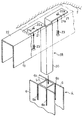
Hereinafter, the partition (1) provided with the 1st Embodiment of this invention is demonstrated, referring FIGS. 1-4.
[0010]
As shown in FIG. 1, a plurality of support columns (4) arranged in the left-right direction between the ceiling (2) and the floor (3) are made of metal corners as shown in FIGS. Weld the right and left sides of the tube (5) with the center of the flat metal plate (6) wider than the front and rear width of the left and right sides of the square tube (5). It is fixed.
As shown in FIG. 3, through holes (6a) are formed at the lower ends of the left and right flat plates (6), and are aligned with the through holes (6a) on both the left and right sides of the square tube (5). Is provided with a screw hole (5a).
[0011]
As shown in FIG. 2 and FIG. 3, horizontal pieces facing upward from the upper ends of the upward pieces (8) are provided with continuous upward pieces (8) from the left and right side edges of the bottom plate (7) long in the front-rear direction. The metal lower fixing member (10) to which the support piece (9) is continuously provided has a countersunk screw (11) inserted into a tapered hole (7a) drilled in the bottom plate (7), and the bottom plate ( 7) and the floor (3), the level is adjusted by interposing an appropriate number of liners (7b) with through holes (not shown) through which countersunk screws (11) can be inserted. And fixed to the floor (3).
Further, a taper hole (8a) is formed in the upward piece (8) from the outside, and a screw hole (9a) is formed in a substantially central portion of the support piece (9).
[0012]
The column (4) is inserted between the left and right upward pieces (8) and (8) so that the through hole (6a) is aligned with the taper hole (8a) and mounted on the bottom plate (7). It is fixed to the lower fixing member (10) by screwing the countersunk screw (12) inserted into the tapered hole (8a) and the through hole (6a) into the screw hole (5a) of the square tube (5). ing.
[0013]
On the left and right sides of the lower fixing member (10), the rail material (13) that faces in the left-right direction and has an upward U-shaped cross section is in a state where the left and right end faces are in contact with the lower fixing member (10). The rail (13) is placed on the floor (3), and is fixed to the floor (3) by a set screw (not shown).
[0014]
(14) is a skirting board having a substantially H-shaped cross section in which the portions slightly lower than the upper ends of the front and rear vertical boards (15) are connected by a horizontal support plate (16). ) Fits the space between the lower end portions of the vertical plate (15) into the upper end portion of the rail member (13), and the side end portion of the support plate (16) as the support piece (9) of the lower fixing member (10). Plate placed on top and having its end surface abutted against the outer surface of the flat plate (6) (see FIG. 2) and inserted into a tapered hole (16a) drilled in the end of the support plate (16) The screw (17) is fixed to the rail member (13) and the lower fixing member (10) by screwing into the screw hole (9a) of the support piece (9).
[0015]
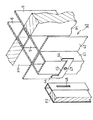
The metal upper fixing member (18) shown in FIG. 4 is for fixing the headboard (19) facing in the left-right direction and the upper end of the column (4) to the ceiling (2).
The upper fixing member (18) is formed by bending a metal plate, and is substantially horizontally oriented in the left-right direction on both the left and right sides of the upper end of the insertion rod (20) whose cross-sectional shape forms a backward U-shape. The attachment piece (21) is continuously provided, and the attachment piece (21) is provided with a tapered hole (21a).
[0016]
The mounting piece (21) is formed on the lower surface of the upper plate (22) of the headboard (19), and the through hole (22a) in which the tapered hole (21a) is formed in the upper plate (22) of the headboard (19) (Fig. 3) (see the phantom line in Fig. 3) and a countersunk screw (23) through the taper hole (21a) and through hole (22a) and screwed into the screw hole (not shown) in the ceiling (2) As a result, the headboard (19) and the upper mounting member (18) are fixed to the ceiling (2).
[0017]
As shown in FIG. 4, the upper end opening of the square tube (5) of the column (4) is fitted to the insertion rod (20) of the upper fixing member (18), and each flat plate (4) of the column (4) ( A pair of front and rear slits (6b) cut from the upper end of 6) are fitted to the front and rear edges of the headboard (19).
[0018]
A glass panel (P1) having a vertically rectangular shape in front view has its lower end placed on the support plate (16) of the skirting board (14), and its upper end is inserted into the headboard (19), and The upper and lower end surfaces are supported by a fixing member (not shown) attached to the inside of the headboard (19) so that the left and right end faces come into contact with the substantially center of the flat plate (6) of the left and right support columns (4) ( 1 and FIG. 2), it is attached between the left and right support columns (4) adjacent to each other.
[0019]
After completion of the partitioning, both flat plates (6) of each column (4) act as partitions or frames of the glass panel (P1), and the gap between the flat plates (6) (6) acts as a joint.
[0020]
The column (4) of the present embodiment described above is obtained by simply welding the square tube (5) and the flat plate (6), each of which can be obtained at low cost and can be easily formed. Therefore, it can be manufactured easily and inexpensively.
[0021]
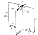
Next, the partition (30) provided with the 2nd Embodiment of this invention is demonstrated, referring FIG.5 and FIG.6.
The same members as those in the first embodiment are designated by the same reference numerals, and detailed description thereof is omitted.
[0022]
In this embodiment, the same support (4) as in the first embodiment is made up of two, and one set of two support (4) is substantially perpendicular to each other in plan view. By connecting the upper and lower portions of both flat plates (6) with a connecting plate (31) having a fan shape in plan view in a state of being close to each other so as to form an L-shaped corner column (34) It is erected between the floor (3) and the ceiling (2).
[0023]
A substantially vertical upright piece (32) is connected to both straight edges of the connecting plate (31), and a tapered hole (32a) is formed in the upright piece (32). This tapered hole (32a) is aligned with the through hole (6c) drilled in the flat plate (6) and the screw hole (5b) drilled in the square tube (5), and the countersunk screw (33) is tapered. The connecting plate (31) is fixed to the flat plate (6) of the support column (4) by being inserted into the through hole (6c) and the screw hole (5b).
[0024]
As in the first embodiment, the side end face of the glass panel (P1) or the like is brought into contact with the flat plate (6) to which the connecting plate (31) is not attached.
[0025]
According to this embodiment, by using the two support columns (4), the two glass panels (P1) orthogonal to each other, the partition panels (not shown), or the glass panel (P1) The L-shaped corner column for connecting the partition panels can be provided easily and inexpensively.
[0026]
Next, the partition (40) provided with the 3rd Embodiment of this invention is demonstrated, referring FIGS. 7-9.
The same members as those in the first embodiment are designated by the same reference numerals, and detailed description thereof is omitted.
[0027]
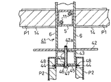
The T-shaped corner column (41) of the present embodiment is substantially the center of the flat plate (42) facing left and right on the front surface of the left and right plates (6) of the same column (4) as in the first embodiment. Are fixed by welding so that the cross-sectional shape is substantially T-shaped. A plurality of screw holes (42a) are formed in the front flat plate (42) in the vertical direction.
[0028]
(43) is a rectangular tubular mounting rod, and through holes (43a) are formed at equal heights at a plurality of locations in the vertical direction on both front and rear surfaces.
After the mounting rod (43) abuts the front surface of the flat plate (42) so that the through hole (43a) is aligned with the screw hole (42a), the left and right width is larger than the left and right width of the mounting rod (43). In addition, a long set screw (47) is passed through the through hole (46) in the locking member (45) provided with an upward locking piece (44) at both left and right ends, and the front and rear of the mounting rod (43) The mounting rod (43) is fixed to the front surface of the flat plate (42) by screwing into the screw hole (42a) of the flat plate (42) through the through hole (43a), and the front surface of the mounting rod (43). The locking member (45) is fixed.
[0029]
A locking hole (48) drilled in the rear end of the inner surface of the partition panel (P2) is engaged with the locking piece (44) protruding leftward and rightward of the mounting rod (43). Thus, the partition panels (P2) are attached to the left and right sides of the attachment rod (43).
[0030]
According to this embodiment, the T-shaped corner column (P1) for connecting the two glass panels (P1) arranged in a straight line and the partition panel (P2) orthogonal to the glass panel (P1) ( 41) can be provided easily and inexpensively.
[0031]
FIG. 10 shows a modification of the third embodiment.
The same members as those in the third embodiment are designated by the same reference numerals, and detailed description thereof is omitted.
[0032]
In this example, instead of directly welding the flat plate (42) to the front surfaces of the left and right flat plates (6) in the support column (4) (third embodiment), the vertical direction is previously set at the center of the rear surface of the flat plate (42). The square tube (49) facing is welded, and this square tube (49) is fitted between the front end portions of the left and right flat plates (6) in the support column (4), and the set screw penetrates them in the front-rear direction. (49a) is fastened to the square tube (5) of the column (4).
The set screw (49a) is configured not to interfere with each other by making the mounting height different from that of the set screw (47).
[0033]
In this modified example, a T-shaped corner is obtained by attaching an integral body of the flat plate (42) and the square tube (49) to the basic column (4) in the first embodiment as necessary. There is an advantage that it is not necessary to prepare a dedicated column for the T-shaped corner.
[0034]
Finally, a partition (50) provided with the fourth embodiment of the present invention will be described with reference to FIGS.
The same members as those in the first embodiment are designated by the same reference numerals, and detailed description thereof is omitted.
[0035]
The support column (51) of this embodiment is formed by fixing the central portion of the flat plate (6) to one side surface (front surface in this embodiment) of the square tube (5) by welding.
[0036]
Square windows (5c) and (6d) communicating with each other are formed in front of the flat plate (6) and the square tube (5), and a circular through hole (5d) is formed on the rear surface of the square tube (5). Is drilled.
As shown in FIG. 11, the support column (51) has the rear surface of the square tube (5) in contact with, for example, a wall (W) and is made into a through hole (5d) using the window holes (5c) and (6d). The inserted set screw (52) is fixed to the wall (W) by screwing into the screw hole (W1) of the wall (W). A glass panel (P1), a partition panel (P2), etc. (all not shown) can be attached by the same procedure as in the above embodiment. At that time, the gap between the flat plate (6) and the wall (W) becomes a joint.
[0037]
Such a column (51) of this embodiment has a simplified structure compared to the columns of the other embodiments described above, and therefore is easier and cheaper to manufacture than the columns of the other embodiments. be able to.
[0038]
【The invention's effect】
According to the first aspect of the present invention, the support column is simply obtained by combining a square tube and a flat plate, which can be obtained at low cost and can be easily formed, and is simply welded. be able to.
In addition, by combining square tubes and flat plates having different dimensions, a wide variety of columns can be manufactured easily and inexpensively without being affected by the number of products produced.
[0039]
According to invention of
[0040]
According to the third aspect of the present invention, the T-shaped corner column for connecting the two panels arranged in a straight line and the panel orthogonal to these panels can be provided easily and inexpensively.
[0041]
According to the invention described in
[Brief description of the drawings]
FIG. 1 is a front view of a partition provided with a first embodiment of the present invention.
FIG. 2 is an enlarged cross-sectional plan view taken along the line II-II in FIG.
FIG. 3 is an enlarged exploded perspective view showing a state where the lower end portion of the support is similarly attached to the floor.
FIG. 4 is an enlarged exploded perspective view showing a state where the upper end portion of the column is attached to the ceiling.
FIG. 5 is a perspective view of a main part of a partition provided with a second embodiment of the present invention.
6 is an enlarged cross-sectional plan view taken along the line VI-VI in FIG.
FIG. 7 is a perspective view of an essential part of a third embodiment of the present invention.
8 is an enlarged cross-sectional plan view taken along line VIII-VIII in FIG.
FIG. 9 is an enlarged exploded perspective view of the main part.
FIG. 10 is a cross-sectional plan view similar to FIG. 8, showing a modification of the third embodiment.
FIG. 11 is an enlarged perspective view of a partition provided with a fourth embodiment of the present invention.
FIG. 12 is an enlarged cross-sectional plan view of the main part of the same.
[Explanation of symbols]
(1) Partition
(2) Ceiling
(3) Floor
(4) Prop
(5) Square tube
(5a) Screw hole
(5b) Screw hole
(5c) Window hole
(5d) Through hole
(6) Flat plate
(6a) Through hole
(6b) Slit
(6c) Through hole
(6d) Window hole
(7) Bottom plate
(7a) Taper hole
(7b) Liner
(8) Upward piece
(8a) Taper hole
(9) Support piece
(10) Lower fixing member
(11) (12) Countersunk screw
(13) Rail material
(14) Skirting board
(15) Vertical plate
(16) Support plate
(16a) Taper hole
(17) Countersunk screw
(18) Upper fixing member
(19) Kasagi
(20) Insertion
(21) Mounting piece
(21a) Taper hole
(22) Upper plate
(22a) Through hole
(30) Partition
(31) Connecting plate
(32) Standing piece
(32a) Taper hole
(33) Countersunk screw
(34) L-shaped corner support
(40) Partition
(41) T-shaped corner support
(42) Flat plate
(42a) Screw hole
(43) Mounting rod
(43a) Through hole
(44) Locking piece
(45) Locking member
(46) Through hole
(47) Set screw
(48) Locking hole
(49) Square tube
(49a) Set screw
(50) Partition
(51) Prop
(52) Set screw
(P1) Glass panel
(P2) Partition panel
(W) Wall
(W1) Screw hole
Claims (4)
Priority Applications (1)
| Application Number | Priority Date | Filing Date | Title |
|---|---|---|---|
| JP20811999A JP4185630B2 (en) | 1999-07-22 | 1999-07-22 | Partition post |
Applications Claiming Priority (1)
| Application Number | Priority Date | Filing Date | Title |
|---|---|---|---|
| JP20811999A JP4185630B2 (en) | 1999-07-22 | 1999-07-22 | Partition post |
Publications (2)
| Publication Number | Publication Date |
|---|---|
| JP2001032416A JP2001032416A (en) | 2001-02-06 |
| JP4185630B2 true JP4185630B2 (en) | 2008-11-26 |
Family
ID=16550959
Family Applications (1)
| Application Number | Title | Priority Date | Filing Date |
|---|---|---|---|
| JP20811999A Expired - Fee Related JP4185630B2 (en) | 1999-07-22 | 1999-07-22 | Partition post |
Country Status (1)
| Country | Link |
|---|---|
| JP (1) | JP4185630B2 (en) |
-
1999
- 1999-07-22 JP JP20811999A patent/JP4185630B2/en not_active Expired - Fee Related
Also Published As
| Publication number | Publication date |
|---|---|
| JP2001032416A (en) | 2001-02-06 |
Similar Documents
| Publication | Publication Date | Title |
|---|---|---|
| JP4185630B2 (en) | Partition post | |
| JP2817630B2 (en) | Partition panel support device | |
| JP2017066720A (en) | Sliding door buttress substrate unit, sliding door buttress structure and manufacturing method thereof | |
| JP2564379Y2 (en) | Wall panel frames for building house walls | |
| JP3221776B2 (en) | Mounting structure of dead weight receiving hardware and dead weight receiving hardware | |
| JP2002138607A (en) | Glass panel system | |
| JP2807206B2 (en) | Exterior wall panels | |
| JP3596455B2 (en) | Connection structure between composite beams and wooden columns | |
| JPS626169Y2 (en) | ||
| JPS5854524Y2 (en) | blind fence | |
| JPH0744644Y2 (en) | Partition panel mounting structure | |
| JP3130352B2 (en) | Beam-to-column joints for building units and method of manufacturing the same | |
| JPS634093Y2 (en) | ||
| JP2928833B2 (en) | Connecting beam | |
| JPH0334136Y2 (en) | ||
| JPH0744649Y2 (en) | Partition panel substructure | |
| JP2867362B2 (en) | Pillar display panel device | |
| JPH0234343Y2 (en) | ||
| JPH0319534Y2 (en) | ||
| JPH04756Y2 (en) | ||
| JP2002138606A (en) | Partition panel system | |
| JP2021139219A (en) | Substrate structure at outer wall side of building | |
| JPH0227796Y2 (en) | ||
| JPH0967920A (en) | Decorative panel | |
| JP2568039B2 (en) | Balcony structure |
Legal Events
| Date | Code | Title | Description |
|---|---|---|---|
| A621 | Written request for application examination |
Free format text: JAPANESE INTERMEDIATE CODE: A621 Effective date: 20060404 |
|
| A977 | Report on retrieval |
Free format text: JAPANESE INTERMEDIATE CODE: A971007 Effective date: 20080121 |
|
| A131 | Notification of reasons for refusal |
Free format text: JAPANESE INTERMEDIATE CODE: A131 Effective date: 20080401 |
|
| A521 | Written amendment |
Free format text: JAPANESE INTERMEDIATE CODE: A523 Effective date: 20080530 |
|
| A131 | Notification of reasons for refusal |
Free format text: JAPANESE INTERMEDIATE CODE: A131 Effective date: 20080715 |
|
| A521 | Written amendment |
Free format text: JAPANESE INTERMEDIATE CODE: A523 Effective date: 20080728 |
|
| TRDD | Decision of grant or rejection written | ||
| A01 | Written decision to grant a patent or to grant a registration (utility model) |
Free format text: JAPANESE INTERMEDIATE CODE: A01 Effective date: 20080902 |
|
| A01 | Written decision to grant a patent or to grant a registration (utility model) |
Free format text: JAPANESE INTERMEDIATE CODE: A01 |
|
| A61 | First payment of annual fees (during grant procedure) |
Free format text: JAPANESE INTERMEDIATE CODE: A61 Effective date: 20080908 |
|
| FPAY | Renewal fee payment (event date is renewal date of database) |
Free format text: PAYMENT UNTIL: 20110912 Year of fee payment: 3 |
|
| R150 | Certificate of patent or registration of utility model |
Free format text: JAPANESE INTERMEDIATE CODE: R150 |
|
| FPAY | Renewal fee payment (event date is renewal date of database) |
Free format text: PAYMENT UNTIL: 20120912 Year of fee payment: 4 |
|
| FPAY | Renewal fee payment (event date is renewal date of database) |
Free format text: PAYMENT UNTIL: 20130912 Year of fee payment: 5 |
|
| LAPS | Cancellation because of no payment of annual fees |