JP4178047B2 - Rebar end fixing device - Google Patents
Rebar end fixing device Download PDFInfo
- Publication number
- JP4178047B2 JP4178047B2 JP2003011151A JP2003011151A JP4178047B2 JP 4178047 B2 JP4178047 B2 JP 4178047B2 JP 2003011151 A JP2003011151 A JP 2003011151A JP 2003011151 A JP2003011151 A JP 2003011151A JP 4178047 B2 JP4178047 B2 JP 4178047B2
- Authority
- JP
- Japan
- Prior art keywords
- reinforcing bar
- fixing plate
- enlarged diameter
- fastening member
- enlarged
- Prior art date
- Legal status (The legal status is an assumption and is not a legal conclusion. Google has not performed a legal analysis and makes no representation as to the accuracy of the status listed.)
- Expired - Fee Related
Links
Images


Description
【0001】
【発明の属する技術分野】
この発明は、コンクリート内に埋設する鉄筋の端部を定着板で拡径し、コンクリートに対する鉄筋の軸方向の引き抜き力に対する定着力を増大させる端部定着装置に関する。
【0002】
【従来の技術】
鉄筋コンクリート構造物や鉄筋、鉄骨コンクリート構造物の構築には、柱用鉄筋や梁用鉄筋等の各種鉄筋が埋設されるが、これらの鉄筋は埋設箇所の強度確保に合わせて鉄筋径や本数、配置間隔等が設定されている。
【0003】
上記のような、コンクリート内に埋設される鉄筋において、柱と梁の接続部分等には、両者の一体性を高めることが、コンクリートの強度確保の上から極めて重要であり、このため、コンクリート内に埋設する鉄筋の端部を予め定着板で拡径し、コンクリートに対する鉄筋の軸方向の定着力を増大させることで、コンクリートの強度を維持する端部定着手段が採用されている。
【0004】
従来の端部定着手段としては、鉄筋の端部をフック状に折り曲げる定着工法や、特開2001−159214号で提案されているように、鉄筋の端部に螺軸を摩擦圧接によって延長状に接続し、この螺軸にナットを用いた定着板を螺合固定し、鉄筋をコンクリート内に埋設したとき、定着板が鉄筋の軸方向の定着力を増大させる端部定着装置が知られている。
【0005】
【発明が解決しようとする課題】
ところで、上記のような鉄筋の端部をフック状に折り曲げる定着工法は、鉄筋の高強度化や太径化により、曲げ加工が困難であったり、定着長さが長くなったりするという問題がある。
また、上記した端部定着装置は、鉄筋と螺軸の接続に摩擦圧接を採用しているが、摩擦圧接のためには高価な設備の導入が必要になると共に、現場で加工ができないため、配筋ミスの修整に時間がかかるという問題がある。
【0006】
そこで、この発明の課題は、上記のような問題を解決するため、鉄筋の端部にこの鉄筋と一体となる拡径部を設け、この拡径部を利用して鉄筋の端部に対する定着板の取り付けを行うようにしたり、ねじ節鉄筋のねじを利用して定着板を固定することで、配筋ミスの修整が簡単にでき、配筋施工の合理化を図ることができると共に、鉄筋への定着板の取り付け強度を増大させることで、配筋強度の信頼性向上が図れ、しかも、簡単な加工設備の使用で現場加工も可能になる鉄筋の端部定着装置を提供することにある。
【0007】
【課題を解決するための手段】
上記のような課題を解決するため、請求項1の発明は、鉄筋の端部に鉄筋よりも大径の拡径部を設け、上記鉄筋に拡径部で抜け止めとなるよう挿入した定着板に拡径部が内部に納まる外嵌孔を設け、この外嵌孔の開口端側に締結部材を螺合した構成を採用したものである。
【0008】
請求項2の発明は、鉄筋の端部に鉄筋よりも大径の拡径部を設け、上記鉄筋に拡径部で抜け止めとなるよう挿入した締結部材と、拡径部を覆うように外嵌した定着板を螺合した構成を採用したものである。
【0009】
請求項3の発明は、鉄筋の端部に鉄筋よりも大径の拡径部を設け、上記鉄筋に拡径部で抜け止めとなる定着板と、この定着板に対して拡径部と反対側に位置する締結部材を挿入し、上記定着板を拡径部と締結部材で挟み込んだ状態で締結部材を鉄筋に固定した構成を採用したものである。
【0010】
請求項4の発明は、鉄筋の端部に鉄筋よりも大径の拡径部を設け、定着板に上記拡径部を通過する内径の挿入孔と、この挿入孔よりも大径のねじ孔とを貫通状に設け、上記鉄筋に嵌合する内径とねじ孔内に納まって拡径部よりも大径となる外径を有する分割抜け止め部材で、鉄筋に挿入した定着板を抜け止め状となるよう保持し、上記拡径部に外嵌する状態で定着板のねじ孔内に締結部材を螺合した構成を採用したものである。
【0011】
請求項5の発明は、鉄筋の端部に鉄筋よりも大径の拡径部を設け、定着板に上記拡径部への外嵌孔と、この外嵌孔よりも大径のねじ孔とを設け、上記鉄筋に嵌合する内径とねじ孔内に納まって拡径部よりも大径となる外径を有する分割抜け止め部材で、鉄筋に挿入した締結部材を抜け止め状となるよう保持し、上記拡径部に外嵌した定着板のねじ孔内に締結部材を螺合した構成を採用したものである。
【0012】
請求項6の発明は、鉄筋にねじ節鉄筋を用い、このねじ節鉄筋に筒体を外嵌螺合し、上記筒体に定着板を外嵌螺合した構成を採用したものである。
【0015】
ここで、拡径部を設ける場合の鉄筋は、丸軸の鉄筋だけでなく、異形鉄筋やねじ節鉄筋を使用することができ、この拡径部は、冷間と熱間の何れを採用してもよく、拡径部は鉄筋の材料から一体に形成されるので、耐引っ張り強度が優れたものとなり、かつ、加工後の強度のバラツキ発生も少ないという利点がある。
【0016】
【発明の実施の形態】
以下、この発明の実施の形態を図示例と共に説明する。
【0017】
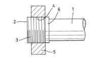
図1に示す第1の実施の形態の端部定着装置は、鉄筋1の端部にこの鉄筋1よりも大径となる円軸状の拡径部2を同軸心となるよう一体に設け、この拡径部2の外周面に雄ねじ3を形成し、内周面に上記雄ねじ3と適合する雌ねじ4を形成した円板状の定着板5を上記拡径部2に外嵌螺合した構造になっている。
【0018】
図2に示す第2の実施の形態の端部定着装置は、上記第1の実施の形態の端部定着装置において、拡径部2の外周面で鉄筋1側の端部に無ねじ部6を残し、雄ねじ3に螺合した定着板5をこの無ねじ部6の位置までねじ込んで固定化することができるようにしたものである。
【0019】
図3に示す第3の実施の形態の端部定着装置は、鉄筋1の端部にこの鉄筋1よりも大径となる円軸状の拡径部2を同軸心となるよう一体に設け、拡径部2に外嵌するよう鉄筋1に取り付けた定着板7に締結部材8を螺合した構造になっている。
【0020】
上記定着板7は、円板や円筒状に形成され、その内径が、鉄筋1に適合する内径の嵌合孔9と拡径部2へ嵌合する内径の外嵌孔11とからなり、外嵌孔11の内周面で開口端側に雌ねじ12が加工されている。
【0021】
また、締結部材8は、外嵌孔11を閉塞する円板状となり、その外周面に雌ねじ12と適合する雄ねじ13が形成されている。
【0022】
上記定着板7は、拡径部2の加工前に鉄筋1へ挿入しておき、拡径部2の加工後に定着板7をスライドさせて上記鉄筋1の拡径部2に外嵌孔11を嵌め、拡径部2で抜け止めとした状態で、外嵌孔11の内部で開口端側に締結部材8を螺合することにより、定着板7と締結部材8で拡径部2を軸方向から挟み込むことにより、鉄筋1に対して定着板7を固定化するものである。
【0023】
図4に示す第4の実施の形態の端部定着装置は、上記第3の実施の形態の端部定着装置において、定着板7に設けた外嵌孔11の内径を拡径部2の外径よりも大径とし、締結部材8をこの外嵌孔11に螺合する外径に設定すると共に、締結部材8に拡径部2への嵌合凹孔14を設けた構造になっている。
【0024】
図5に示す第5の実施の形態の端部定着装置は、鉄筋1の端部にこの鉄筋1よりも大径となる円軸状の拡径部2を同軸心となるよう一体に設け、拡径部2に外嵌させた定着板15と鉄筋1に挿入した締結部材16を螺合した構造になっている。
【0025】
上記定着板15は、拡径部2に対する有底状の外嵌孔17と、この外嵌孔17よりも大径で一面側に開口する雌ねじ孔18とを設けて形成され、また、締結部材16は鉄筋1に嵌合する内径で、雌ねじ孔18に対して外径の雄ねじ19を螺合するようになっている。
【0026】
締結部材16は、拡径部2の加工前に鉄筋1へ挿入しておき、拡径部2の加工後に定着板15の外嵌孔17を拡径部2に嵌め、締結部材16を定着板15の雌ねじ孔18に螺合すれば、定着板15と締結部材16で拡径部2を軸方向から挟み込むことにより、鉄筋1に対して定着板15を固定化するものである。
【0027】
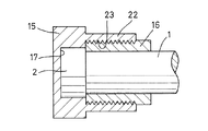
図6に示す第6の実施の形態の端部定着装置は、上記第5の実施の形態の端部定着装置において、定着板15には、拡径部2に対する有底状の外嵌孔17だけを設け、この外嵌孔17を拡径部2よりも大径とし、その内周面に雌ねじ20を加工すると共に、締結部材16は、外嵌孔17に螺合する外径にすると共に、拡径部2に対して外嵌する嵌合凹孔21を設けた構造になっている。
【0028】
図7に示す第7の実施の形態の端部定着装置は、上記第5の実施の形態の端部定着装置において、定着板15の鉄筋1に対する外嵌部分を一段小径の円筒部22とし、この円筒部22の内面に雌ねじ23を形成し、締結部材16は、上記円筒部22内に螺合する長い円筒状に形成した構造になっている。
【0029】
図8に示す第8の実施の形態の端部定着装置は、鉄筋1の端部にこの鉄筋1よりも大径となる円軸状の拡径部2を同軸心となるよう一体に設け、上記鉄筋1に拡径部2で抜け止めとなる環状の定着板24と、この定着板24に対して拡径部2と反対側に位置する円板状の締結部材25を挿入し、上記定着板24を拡径部2と締結部材25で挟み込んだ状態で、締結部材25を外周から螺入したビス25aの締め付けで鉄筋1に固定し、鉄筋1に対して定着板24を固定化するようにしたものであり、定着板24と締結部材25は、拡径部2の加工前に鉄筋1へ挿入しておき、拡径部2の加工後に、定着板24と締結部材25を拡径部2側にスライドさせ、図示のように定着板24を鉄筋1に対して固定化する。
【0030】
図9に示す第9の実施の形態の端部定着装置は、鉄筋1の端部にこの鉄筋1よりも大径となる円軸状の拡径部2を同軸心となるよう一体に設け、定着板26に上記拡径部2を通過する内径の挿入孔27と、この挿入孔27よりも大径のねじ孔28とを貫通状に設け、分割抜け止め部材29と締結部材30を用いて定着板26を鉄筋1に対して固定化するようにしたものである。
【0031】
上記分割抜け止め部材29は、鉄筋1に嵌合する内径と拡径部2の外径に等しい外径を有し、鉄筋1に外嵌する半筒状部31の端部に、定着板26のねじ孔28内に納まって拡径部2よりも大径となる外径を有する係合突条32を設け、二つ割りにした構造になっている。
【0032】
この分割抜け止め部材29は、端部に拡径部2を加工した鉄筋1に対して、係合突条32が拡径部2側に位置するよう外嵌して組み立て、鉄筋1に挿入してある定着板26を拡径部2側に移動させてその挿入孔27を半筒状部31に嵌合させれば、分割抜け止め部材29は筒状に保持され、ねじ孔28が拡径部2の外側に位置し、係合突条32が拡径部2の段部に当接すると共に、挿入孔27とねじ孔28の段部が係合突条32に当接することで、定着板26は拡径部2側に抜け止め状態となる。
【0033】
また、締結部材30は、上記拡径部2に外嵌するキャツプ状に形成され、外径面の雄ねじ33を鉄筋1に挿入した定着板26のねじ孔28に螺合することにより、定着板26と締結部材30で係合突条32を軸方向から挟むことで、鉄筋1に定着板26を固定化するようになっている。
【0034】
図10に示す第10の実施の形態の端部定着装置は、上記第9の実施の形態の変形例であり、定着板26に拡径部2への外嵌孔34と、この外嵌孔34よりも大径のねじ孔35とを設け、締結部材30は、分割抜け止め部材29の半筒状部31に嵌合する内径の筒状に形成され、定着板26の外嵌孔34を拡径部2に嵌合した状態で、鉄筋1に挿入してある締結部材30を定着板26のねじ孔35に螺合すれば、分割抜け止め部材29は筒状に保持され、係合突条32が拡径部2の段部に当接すると共に、締結部材30の端部が係合突条32に当接することで、定着板26は拡径部2側に抜け止め状態の固定となる。
【0035】
この第9と第10の実施の形態のように、二つ割りの分割抜け止め部材29を用い、定着板26の挿入孔27とねじ孔28又は外嵌孔34とねじ孔35の径を上記のように設定することにより、鉄筋1に対して端部に拡径部2を加工した後、鉄筋1に定着板26を挿入することができ、定着板26の後付けを可能とすることにより、現場での定着板26の取り付け作業が円滑に行えることになる。
【0036】
図11に示す第11の実施の形態の端部定着装置は、鉄筋にねじ節鉄筋1aを用い、外周面に雄ねじ1bが形成されたねじ節鉄筋1aに外嵌する筒体36の内周面に、上記雄ねじ1bに螺合する雌ねじ37を加工し、この筒体36の外周面に形成した雄ねじ38に定着板39を外嵌螺合することにより、鉄筋1aに定着板39を固定するようにしたものである。
【0037】
図12に示す第12の実施の形態の端部定着装置は、鉄筋にねじ節鉄筋1aを用い、外周面に雄ねじ1bが形成されたねじ節鉄筋1aに定着板39を直接外嵌し、この定着板39を挟む両側の位置に、上記雄ねじ1bに螺合する雌ねじ40を加工した締結部材41を螺合し、締結部材41で定着板39を両側から締め付けることにより、定着板39を鉄筋1aに固定化するようにしたものである。
【0038】
上記定着板39は、その内径にねじ節鉄筋1aに螺合する雌ねじを加工したものでもよい。
【0039】
このように、ねじ節鉄筋1aの雄ねじ1bを利用して定着板39をねじ節鉄筋1aに固定するようにすれば、筒体36や定着板39にねじを加工するだけでよく、定着板39の端部定着装置の構造を簡略化することができる。
【0040】
なお、第1乃至第10の実施の形態において、鉄筋1は丸軸の鉄筋だけでなく、異形鉄筋やねじ節鉄筋を使用することができ、鉄筋1の端部に設ける拡径部2は、その外径を形成する金型内において、鉄筋1を軸方向に加圧することで拡径させ、円軸状に仕上げるものであり、拡径加工は冷間と熱間の何れを採用してもよい。
【0041】
また、拡径部2は鉄筋1から一体に形成されるので、摩擦圧接のような接続とは異なり、材料の一体化により耐引っ張り強度が優れたものとなり、加工後の強度のバラツキ発生も少ないものである。
【0042】
更に、鉄筋1に対する拡径部2の外径や長さは、耐引っ張り強度を向上させる範囲で任意に設定すればよく、また、定着板5、7、15、24の外径や形状も円形以外に、角形や多角形、折れ曲がり部分を備えた形状等、定着強度を確保する範囲で設定すればよい。
【0043】
この発明の端部定着装置は、上記のような構成であり、第1乃至第10の実施の形態において、コンクリート内に埋設される鉄筋の、柱と梁の接続部分等に臨む端部に拡径部2を鉄筋1と一体に加工すると共に、定着板5もしくは定着板7、15、24と締結部材8、16、25を用い、拡径部2を軸方向の抜け止めに利用して、鉄筋1の端部に定着板5、7、15、24を固定化すれば、定着板5、7、15、24によって鉄筋1の端部が拡径化されることになり、コンクリート内に埋設された鉄筋1は、定着板5、7、15、24によって軸方向への移動が阻止されて定着力が増大し、コンクリートの強度を維持することになる。
【0044】
上記第3乃至第10の実施の形態は、拡径部2に雄ねじの加工が不要になるので、現場において拡径部2の加工が可能になり、配筋ミスの修整が簡単にできるという利点があり、また、第11乃至第12の実施の形態は、ねじ節鉄筋1aの雄ねじ1bを利用するので、現場での鉄筋の加工が一切不要になり、上記と同様の利点がある。
【0045】
【発明の効果】
以上のように、この発明によると、鉄筋の端部に鉄筋よりも大径の拡径部を設け、拡径部を軸方向の抜け止めに利用して、鉄筋の端部に定着板を固定化するようにしたので、鉄筋の拡径部は、鉄筋と一体化しているので、耐引っ張り強度に優れ、耐引っ張り強度のバラツキの発生もないので、鉄筋端部への定着板の取り付け強度を増大させることができ、定着力の増大による配筋の信頼性向上が図れることになる。
【0046】
また、鉄筋と一体化した拡径部の加工は、鉄筋を軸方向に加圧することで形成でき、摩擦圧接のような高価な設備が不要になるので、コスト的に廉価な端部定着装置を提供することができる。
【0047】
更に、ねじ節鉄筋の雄ねじを利用して定着板をねじ節鉄筋に固定するようにすれば、筒体や定着板にねじを加工するだけでよく、定着板の端部定着装置の構造を簡略化することができる。
【図面の簡単な説明】
【図1】この発明に係る鉄筋の端部定着装置における第1の実施の形態を示す縦断正面図
【図2】この発明に係る鉄筋の端部定着装置における第2の実施の形態を示す縦断正面図
【図3】この発明に係る鉄筋の端部定着装置における第3の実施の形態を示す縦断正面図
【図4】この発明に係る鉄筋の端部定着装置における第4の実施の形態を示す縦断正面図
【図5】この発明に係る鉄筋の端部定着装置における第5の実施の形態を示す縦断正面図
【図6】この発明に係る鉄筋の端部定着装置における第6の実施の形態を示す縦断正面図
【図7】この発明に係る鉄筋の端部定着装置における第7の実施の形態を示す縦断正面図
【図8】この発明に係る鉄筋の端部定着装置における第8の実施の形態を示す縦断正面図
【図9】この発明に係る鉄筋の端部定着装置における第9の実施の形態を示す縦断正面図
【図10】この発明に係る鉄筋の端部定着装置における第10の実施の形態を示す縦断正面図
【図11】この発明に係る鉄筋の端部定着装置における第11の実施の形態を示す縦断正面図
【図12】この発明に係る鉄筋の端部定着装置における第12の実施の形態を示す縦断正面図
【符号の説明】
1 鉄筋
1a ねじ節鉄筋
2 拡径部
3 雄ねじ
4 雌ねじ
5 定着板
6 無ねじ部
7 定着板
8 締結部材
9 嵌合孔
11 外嵌孔
12 雌ねじ
13 雄ねじ
14 嵌合凹孔
15 定着板
16 締結部材
17 外嵌孔
18 雌ねじ孔
19 雄ねじ
20 雌ねじ
21 嵌合凹孔
22 円筒部
23 雌ねじ
24 定着板
25 締結部材
26 定着板
27 挿入孔
28 ねじ孔
29 分割抜け止め部材
30 締結部材
31 半筒状部
32 係合突条
33 雄ねじ
34 外嵌孔
35 ねじ孔
36 筒体
37 雌ねじ
38 雄ねじ
39 定着板
40 雌ねじ
41 締結部材[0001]
BACKGROUND OF THE INVENTION
The present invention relates to an end fixing device in which an end portion of a reinforcing bar embedded in concrete is expanded in diameter by a fixing plate to increase a fixing force against an axial pull-out force of the reinforcing bar with respect to concrete.
[0002]
[Prior art]
Reinforced concrete structures, reinforcing bars, and steel-framed concrete structures are built with various types of reinforcing bars such as column reinforcing bars and beam reinforcing bars. An interval is set.
[0003]
In the reinforcing bars embedded in concrete as described above, it is extremely important to secure the strength of the concrete at the connecting part between the column and the beam. The end fixing means for maintaining the strength of the concrete is employed by expanding the diameter of the end of the reinforcing bar embedded in the steel plate in advance with a fixing plate and increasing the fixing force in the axial direction of the reinforcing bar against the concrete.
[0004]
As a conventional end fixing means, a fixing method for bending the end of a reinforcing bar into a hook shape, or as proposed in Japanese Patent Laid-Open No. 2001-159214, a screw shaft is extended to the end of a reinforcing bar by friction welding. An end fixing device is known in which the fixing plate increases the fixing force in the axial direction of the reinforcing bar when the fixing plate using the nut is screwed and fixed to the screw shaft and the reinforcing bar is embedded in the concrete. .
[0005]
[Problems to be solved by the invention]
By the way, the fixing method of bending the ends of the reinforcing bars as described above has a problem that the bending process is difficult or the fixing length becomes long due to the strengthening and thickening of the reinforcing bars. .
In addition, the above-described end fixing device employs friction welding for connection between the reinforcing bar and the screw shaft, but for friction welding, it is necessary to introduce expensive equipment and processing on site is not possible. There is a problem that it takes time to correct the arrangement error.
[0006]
Therefore, in order to solve the above-described problems, an object of the present invention is to provide an enlarged diameter portion integrated with the reinforcing bar at an end portion of the reinforcing bar, and use the enlarged diameter portion to fix the fixing plate to the reinforcing bar end portion. By fixing the fixing plate using the screws of the screw joint reinforcing bar, it is possible to easily correct the bar arrangement error, rationalize the bar arrangement work, and to reinforce the reinforcing bar. It is an object of the present invention to provide a reinforcing bar end fixing device that can improve the reliability of reinforcing bar arrangement strength by increasing the fixing strength of the fixing plate, and that can be processed on site by using simple processing equipment.
[0007]
[Means for Solving the Problems]
In order to solve the above-mentioned problems, the invention of
[0008]
The invention according to
[0009]
The invention according to
[0010]
According to the invention of
[0011]
The invention of
[0012]
The invention of
[0015]
Here, the reinforcing bar in the case of providing the enlarged diameter part can use not only a round shaft reinforcing bar, but also a deformed reinforcing bar and a threaded reinforcing bar, and this enlarged diameter part adopts either cold or hot. In addition, since the enlarged diameter portion is integrally formed from the material of the reinforcing bar, there is an advantage that the tensile strength is excellent and there is little variation in strength after processing.
[0016]
DETAILED DESCRIPTION OF THE INVENTION
Hereinafter, embodiments of the present invention will be described with reference to the drawings.
[0017]
The end fixing device according to the first embodiment shown in FIG. 1 is provided integrally with an end portion of a reinforcing
[0018]
The end fixing device according to the second embodiment shown in FIG. 2 is the same as the end fixing device according to the first embodiment, except that the
[0019]
The end fixing device according to the third embodiment shown in FIG. 3 is provided integrally with an end portion of the reinforcing
[0020]
The
[0021]
Moreover, the fastening
[0022]
The
[0023]
The end fixing device according to the fourth embodiment shown in FIG. 4 is the same as the end fixing device according to the third embodiment described above except that the inner diameter of the outer
[0024]
The end fixing device according to the fifth embodiment shown in FIG. 5 is provided integrally with an end portion of the reinforcing
[0025]
The fixing
[0026]
The
[0027]
The end fixing device of the sixth embodiment shown in FIG. 6 is the same as the end fixing device of the fifth embodiment, but the fixing
[0028]
The end fixing device of the seventh embodiment shown in FIG. 7 is the same as the end fixing device of the fifth embodiment, except that the outer fitting portion of the fixing
[0029]
The end fixing device according to the eighth embodiment shown in FIG. 8 is provided integrally with an end portion of the reinforcing
[0030]
The end fixing device of the ninth embodiment shown in FIG. 9 is provided integrally with an end portion of the reinforcing
[0031]
The
[0032]
The
[0033]
In addition, the
[0034]
The end fixing device according to the tenth embodiment shown in FIG. 10 is a modification of the ninth embodiment, and the fixing
[0035]
As in the ninth and tenth embodiments, a split split retaining
[0036]
The end fixing device of the eleventh embodiment shown in FIG. 11 uses an inner peripheral surface of a
[0037]
The end fixing device according to the twelfth embodiment shown in FIG. 12 uses a screw joint reinforcing
[0038]
The fixing
[0039]
As described above, if the fixing
[0040]
In the first to tenth embodiments, the reinforcing
[0041]
In addition, since the
[0042]
Furthermore, the outer diameter and length of the
[0043]
The end fixing device of the present invention has the above-described configuration, and in the first to tenth embodiments, the end fixing device extends to the end of the reinforcing bar embedded in the concrete that faces the connecting portion of the column and the beam. While processing the
[0044]
The third to tenth embodiments do not require a male thread in the
[0045]
【The invention's effect】
As described above, according to the present invention, an enlarged diameter portion larger than the reinforcing bar is provided at the end portion of the reinforcing bar, and the fixing plate is fixed to the end portion of the reinforcing bar by using the enlarged diameter portion for preventing axial disengagement. Since the expanded diameter part of the reinforcing bar is integrated with the reinforcing bar, it has excellent tensile strength and there is no variation in tensile strength. The reliability of the bar arrangement can be improved by increasing the fixing force.
[0046]
In addition, the processing of the enlarged diameter part integrated with the reinforcing bar can be formed by pressing the reinforcing bar in the axial direction, eliminating the need for expensive equipment such as friction welding. Can be provided.
[0047]
Furthermore, if the fixing plate is fixed to the screw joint using the male screw of the screw joint, the structure of the fixing device at the end of the fixing plate can be simplified. Can be
[Brief description of the drawings]
FIG. 1 is a longitudinal front view showing a first embodiment of a reinforcing bar end fixing device according to the present invention. FIG. 2 is a longitudinal sectional view showing a second embodiment of a reinforcing bar end fixing device according to the present invention. FIG. 3 is a longitudinal sectional front view showing a third embodiment of the reinforcing bar end fixing device according to the present invention. FIG. 4 is a fourth embodiment of the reinforcing bar end fixing device according to the present invention. FIG. 5 is a longitudinal front view showing a fifth embodiment of the reinforcing bar end fixing device according to the present invention. FIG. 6 is a sixth embodiment of the reinforcing bar end fixing device according to the present invention. FIG. 7 is a longitudinal front view showing a seventh embodiment of the reinforcing bar end fixing device according to the present invention. FIG. 8 is an eighth embodiment of the reinforcing bar end fixing device according to the present invention. FIG. 9 is a longitudinal sectional front view showing an embodiment. FIG. 10 is a longitudinal front view showing the ninth embodiment of the end fixing device. FIG. 10 is a longitudinal front view showing the tenth embodiment of the end fixing device for reinforcing bars. FIG. 12 is a longitudinal front view showing an eleventh embodiment of the reinforcing bar end fixing device. FIG. 12 is a longitudinal front view showing a twelfth embodiment of the reinforcing bar end fixing device according to the present invention.
DESCRIPTION OF
Claims (6)
Priority Applications (1)
| Application Number | Priority Date | Filing Date | Title |
|---|---|---|---|
| JP2003011151A JP4178047B2 (en) | 2003-01-20 | 2003-01-20 | Rebar end fixing device |
Applications Claiming Priority (1)
| Application Number | Priority Date | Filing Date | Title |
|---|---|---|---|
| JP2003011151A JP4178047B2 (en) | 2003-01-20 | 2003-01-20 | Rebar end fixing device |
Publications (2)
| Publication Number | Publication Date |
|---|---|
| JP2004225261A JP2004225261A (en) | 2004-08-12 |
| JP4178047B2 true JP4178047B2 (en) | 2008-11-12 |
Family
ID=32900136
Family Applications (1)
| Application Number | Title | Priority Date | Filing Date |
|---|---|---|---|
| JP2003011151A Expired - Fee Related JP4178047B2 (en) | 2003-01-20 | 2003-01-20 | Rebar end fixing device |
Country Status (1)
| Country | Link |
|---|---|
| JP (1) | JP4178047B2 (en) |
Families Citing this family (3)
| Publication number | Priority date | Publication date | Assignee | Title |
|---|---|---|---|---|
| JP7002182B2 (en) | 2014-09-24 | 2022-01-20 | 株式会社大林組 | Connection structure |
| CN105064615B (en) * | 2015-07-17 | 2018-04-17 | 上海核工程研究设计院 | A kind of steel bar anchoring device and installation method |
| CN109778613B (en) * | 2019-03-01 | 2023-12-19 | 河间市银龙轨道有限公司 | Automatic installation locking device for anchor plate |
-
2003
- 2003-01-20 JP JP2003011151A patent/JP4178047B2/en not_active Expired - Fee Related
Also Published As
| Publication number | Publication date |
|---|---|
| JP2004225261A (en) | 2004-08-12 |
Similar Documents
| Publication | Publication Date | Title |
|---|---|---|
| RU2477816C2 (en) | Single integral radially crumpled snap ring, and its manufacturing method | |
| JP3703833B2 (en) | Joint forming device | |
| CA2586762C (en) | Clamp for securing a tubular or hose-shaped object | |
| EP0804688B1 (en) | Blind fastener and blind fixing method | |
| KR101627166B1 (en) | Manufacturing method of collet for biting iron rod and coupling apparatus for iron rod | |
| JP4178047B2 (en) | Rebar end fixing device | |
| JP2011163533A (en) | Pipe joint | |
| JPH06101284A (en) | Clamping structure and nut used for this structure | |
| JP2017145885A (en) | Reinforcement jig for junction and reinforcement structure for junction | |
| JPH08319696A (en) | Screw joint for steel bar and joint fitting | |
| JP5137195B2 (en) | Pipe fitting | |
| JP2009161938A (en) | Screwing mechanism and temporary assembling metal fixture for construction using the same | |
| JP2018100678A (en) | Male screw member | |
| JP4687040B2 (en) | Connection device for concrete components | |
| JP2008177041A (en) | Battery terminal connecting tool and connecting method of terminal | |
| JP2004270204A (en) | Joint structure of steel pipe and joining method of steel pipe | |
| SK120896A3 (en) | Apparatus for attachment of pipes | |
| JP4578029B2 (en) | Pile head structure and pile head bracket | |
| EP1067248A2 (en) | Anchoring device for building components made of concrete or the like with easy-to-apply element for anchoring to the component | |
| JP4056736B2 (en) | Pipe fitting | |
| JP5221225B2 (en) | Pipe joint | |
| JPH0280798A (en) | Fixing structure for water-proof sheet and hanging reinforcing bar | |
| JPH11201131A (en) | Locking bush for bolt | |
| JP3020439U (en) | Tarup | |
| JP2009019652A (en) | Pipe joint |
Legal Events
| Date | Code | Title | Description |
|---|---|---|---|
| A621 | Written request for application examination |
Free format text: JAPANESE INTERMEDIATE CODE: A621 Effective date: 20060116 |
|
| A977 | Report on retrieval |
Free format text: JAPANESE INTERMEDIATE CODE: A971007 Effective date: 20070531 |
|
| A131 | Notification of reasons for refusal |
Free format text: JAPANESE INTERMEDIATE CODE: A131 Effective date: 20080415 |
|
| A521 | Written amendment |
Free format text: JAPANESE INTERMEDIATE CODE: A523 Effective date: 20080612 |
|
| TRDD | Decision of grant or rejection written | ||
| A01 | Written decision to grant a patent or to grant a registration (utility model) |
Free format text: JAPANESE INTERMEDIATE CODE: A01 Effective date: 20080805 |
|
| A01 | Written decision to grant a patent or to grant a registration (utility model) |
Free format text: JAPANESE INTERMEDIATE CODE: A01 |
|
| A61 | First payment of annual fees (during grant procedure) |
Free format text: JAPANESE INTERMEDIATE CODE: A61 Effective date: 20080825 |
|
| FPAY | Renewal fee payment (event date is renewal date of database) |
Free format text: PAYMENT UNTIL: 20110829 Year of fee payment: 3 |
|
| R150 | Certificate of patent or registration of utility model |
Free format text: JAPANESE INTERMEDIATE CODE: R150 |
|
| FPAY | Renewal fee payment (event date is renewal date of database) |
Free format text: PAYMENT UNTIL: 20120829 Year of fee payment: 4 |
|
| LAPS | Cancellation because of no payment of annual fees |