JP4174107B2 - Solar energy panels and solar energy roofs - Google Patents
Solar energy panels and solar energy roofs Download PDFInfo
- Publication number
- JP4174107B2 JP4174107B2 JP26312698A JP26312698A JP4174107B2 JP 4174107 B2 JP4174107 B2 JP 4174107B2 JP 26312698 A JP26312698 A JP 26312698A JP 26312698 A JP26312698 A JP 26312698A JP 4174107 B2 JP4174107 B2 JP 4174107B2
- Authority
- JP
- Japan
- Prior art keywords
- solar energy
- energy utilization
- panel
- roof
- draining
- Prior art date
- Legal status (The legal status is an assumption and is not a legal conclusion. Google has not performed a legal analysis and makes no representation as to the accuracy of the status listed.)
- Expired - Fee Related
Links
Images


Classifications
-
- F—MECHANICAL ENGINEERING; LIGHTING; HEATING; WEAPONS; BLASTING
- F24—HEATING; RANGES; VENTILATING
- F24S—SOLAR HEAT COLLECTORS; SOLAR HEAT SYSTEMS
- F24S40/00—Safety or protection arrangements of solar heat collectors; Preventing malfunction of solar heat collectors
- F24S40/40—Preventing corrosion; Protecting against dirt or contamination
- F24S40/44—Draining rainwater or condensation
-
- F—MECHANICAL ENGINEERING; LIGHTING; HEATING; WEAPONS; BLASTING
- F24—HEATING; RANGES; VENTILATING
- F24S—SOLAR HEAT COLLECTORS; SOLAR HEAT SYSTEMS
- F24S20/00—Solar heat collectors specially adapted for particular uses or environments
- F24S20/60—Solar heat collectors integrated in fixed constructions, e.g. in buildings
- F24S20/67—Solar heat collectors integrated in fixed constructions, e.g. in buildings in the form of roof constructions
-
- F—MECHANICAL ENGINEERING; LIGHTING; HEATING; WEAPONS; BLASTING
- F24—HEATING; RANGES; VENTILATING
- F24S—SOLAR HEAT COLLECTORS; SOLAR HEAT SYSTEMS
- F24S25/00—Arrangement of stationary mountings or supports for solar heat collector modules
- F24S25/30—Arrangement of stationary mountings or supports for solar heat collector modules using elongate rigid mounting elements extending substantially along the supporting surface, e.g. for covering buildings with solar heat collectors
- F24S25/33—Arrangement of stationary mountings or supports for solar heat collector modules using elongate rigid mounting elements extending substantially along the supporting surface, e.g. for covering buildings with solar heat collectors forming substantially planar assemblies, e.g. of coplanar or stacked profiles
-
- F—MECHANICAL ENGINEERING; LIGHTING; HEATING; WEAPONS; BLASTING
- F24—HEATING; RANGES; VENTILATING
- F24S—SOLAR HEAT COLLECTORS; SOLAR HEAT SYSTEMS
- F24S20/00—Solar heat collectors specially adapted for particular uses or environments
- F24S2020/10—Solar modules layout; Modular arrangements
- F24S2020/12—Coplanar arrangements with frame overlapping portions
-
- Y—GENERAL TAGGING OF NEW TECHNOLOGICAL DEVELOPMENTS; GENERAL TAGGING OF CROSS-SECTIONAL TECHNOLOGIES SPANNING OVER SEVERAL SECTIONS OF THE IPC; TECHNICAL SUBJECTS COVERED BY FORMER USPC CROSS-REFERENCE ART COLLECTIONS [XRACs] AND DIGESTS
- Y02—TECHNOLOGIES OR APPLICATIONS FOR MITIGATION OR ADAPTATION AGAINST CLIMATE CHANGE
- Y02A—TECHNOLOGIES FOR ADAPTATION TO CLIMATE CHANGE
- Y02A30/00—Adapting or protecting infrastructure or their operation
- Y02A30/60—Planning or developing urban green infrastructure
-
- Y—GENERAL TAGGING OF NEW TECHNOLOGICAL DEVELOPMENTS; GENERAL TAGGING OF CROSS-SECTIONAL TECHNOLOGIES SPANNING OVER SEVERAL SECTIONS OF THE IPC; TECHNICAL SUBJECTS COVERED BY FORMER USPC CROSS-REFERENCE ART COLLECTIONS [XRACs] AND DIGESTS
- Y02—TECHNOLOGIES OR APPLICATIONS FOR MITIGATION OR ADAPTATION AGAINST CLIMATE CHANGE
- Y02B—CLIMATE CHANGE MITIGATION TECHNOLOGIES RELATED TO BUILDINGS, e.g. HOUSING, HOUSE APPLIANCES OR RELATED END-USER APPLICATIONS
- Y02B10/00—Integration of renewable energy sources in buildings
- Y02B10/10—Photovoltaic [PV]
-
- Y—GENERAL TAGGING OF NEW TECHNOLOGICAL DEVELOPMENTS; GENERAL TAGGING OF CROSS-SECTIONAL TECHNOLOGIES SPANNING OVER SEVERAL SECTIONS OF THE IPC; TECHNICAL SUBJECTS COVERED BY FORMER USPC CROSS-REFERENCE ART COLLECTIONS [XRACs] AND DIGESTS
- Y02—TECHNOLOGIES OR APPLICATIONS FOR MITIGATION OR ADAPTATION AGAINST CLIMATE CHANGE
- Y02B—CLIMATE CHANGE MITIGATION TECHNOLOGIES RELATED TO BUILDINGS, e.g. HOUSING, HOUSE APPLIANCES OR RELATED END-USER APPLICATIONS
- Y02B10/00—Integration of renewable energy sources in buildings
- Y02B10/20—Solar thermal
-
- Y—GENERAL TAGGING OF NEW TECHNOLOGICAL DEVELOPMENTS; GENERAL TAGGING OF CROSS-SECTIONAL TECHNOLOGIES SPANNING OVER SEVERAL SECTIONS OF THE IPC; TECHNICAL SUBJECTS COVERED BY FORMER USPC CROSS-REFERENCE ART COLLECTIONS [XRACs] AND DIGESTS
- Y02—TECHNOLOGIES OR APPLICATIONS FOR MITIGATION OR ADAPTATION AGAINST CLIMATE CHANGE
- Y02E—REDUCTION OF GREENHOUSE GAS [GHG] EMISSIONS, RELATED TO ENERGY GENERATION, TRANSMISSION OR DISTRIBUTION
- Y02E10/00—Energy generation through renewable energy sources
- Y02E10/40—Solar thermal energy, e.g. solar towers
- Y02E10/47—Mountings or tracking
Landscapes
- Engineering & Computer Science (AREA)
- Physics & Mathematics (AREA)
- Life Sciences & Earth Sciences (AREA)
- Sustainable Development (AREA)
- Sustainable Energy (AREA)
- Thermal Sciences (AREA)
- Chemical & Material Sciences (AREA)
- Combustion & Propulsion (AREA)
- Mechanical Engineering (AREA)
- General Engineering & Computer Science (AREA)
- Roof Covering Using Slabs Or Stiff Sheets (AREA)
- Photovoltaic Devices (AREA)
Description
【0001】
【発明の属する技術分野】
本発明は、屋根の傾斜面に沿って設けられる太陽エネルギー利用パネルおよび太陽エネルギー利用屋根に関するものである。
【0002】
【背景技術】
従来より、太陽光を電気に変換して太陽エネルギーとして利用する太陽電池パネルや、太陽熱(放射熱)を収集して温水として利用する太陽熱コレクタ等の太陽エネルギー利用パネルがある。このようなパネルを住宅等の屋根の傾斜面に沿って上下左右に複数枚設置することにより、太陽エネルギー利用屋根が構成されている。
【0003】
このうち、太陽電池パネルは、屋根に設置するに当たり、水による漏電等の事故を未然に防止するため、太陽電池である所定枚数のソーラーセルを平板状の完全防水ケースの内部に収め、この防水ケースの周りに四角枠状のフレームを設け、このフレームを屋根に付けている。このような取付構造は、太陽熱コレクタにも応用できる。
【0004】
このような太陽エネルギー利用パネルを屋根の傾斜上に上下に配列するにあたり、屋根面の水はけを良くし、その防水性能を確保する必要がある。このために、フレームの上枠部に樋部、下枠部に水切り部を設け、下方に配置される太陽エネルギー利用パネルの樋部の上に、上方に配置される別の太陽エネルギー利用パネルの水切り部を配置し、これらの太陽エネルギー利用パネルの隙間に雨水等が浸入しても、雨水等の水を水切り部で樋部へ導いて排水を促している。これにより、防水性能が確保されるようになっている(特開平10−169127号公報等参照)。
ここで、水切り部が下方に長く延びていると、太陽エネルギー利用パネルの取付作業時に水切り部が変形し易くなり、変形すると修正に時間がかかり、取付作業を長引かせるので、水切り部の下方への延出寸法は最小限に設定されている。
【0005】
また、勾配を有する屋根面に上下方向に配列された太陽エネルギー利用パネルのうち、最下位置となる太陽エネルギー利用パネルの下枠部には、当該下枠部から軒先まで延びて、太陽エネルギー利用パネルが取り付けられない余白部分を覆う面戸板が設けられている。
【0006】
【発明が解決しようとする課題】
このような太陽エネルギー利用パネルでは、水切り部の長さ寸法が最小限とされていることから、水切り部には、面戸板を取り付ける余地がないので、水切り部を切り取って、その内側にある下枠部に面戸板を取り付けなければならず、水切り部を切り取る作業が面倒となり、太陽エネルギー利用パネルの設置作業に時間がかかるという問題がある。
一方、面戸板を取り付けるために水切り部が省略された専用の下枠部を用意しておくことも考えられるが、下枠部の種類が増えてしまい、フレームの製造効率が損なわれるという問題がある。
【0007】
本発明の目的は、フレームの製造効率を損なうことなく、設置作業が容易となる太陽エネルギー利用パネルおよび太陽エネルギー利用屋根を提供することにある。
【0008】
【課題を解決するための手段】
本発明の第1発明は、図面を参照して説明すると、防水ケース22の周りを囲む四角枠状のフレーム23を備えた太陽エネルギー利用パネル(例えば、太陽電池パネル21)であって、フレーム23の上枠部25には、上方が開口された溝形の樋部53が設けられ、フレーム23の下枠部26は、本体61と、前記本体61の側面上部から外側に向かって水平に突出したつば部62とを有し、このつば部62の下面に水切り部63が突設され、この水切り部63の中間部分と本体61の側面とを連結する中間連結部64が設けられ、前記水切り部63の先端部が前記樋部53の開口に臨む位置に形成され、前記中間連結部64は、その一端部が前記水切り部63の中間部に連結され、その他端部が前記樋部53より離れた位置で前記本体61の側面に連結されていることを特徴とする。
このような本発明では、水切り部の基端部分をつば部に連結し、中間部分を中間連結部に連結したので、従来のように、つば部を単に突設していた場合に比べて、同じ厚さでも水切り部の剛性が大きくなり、これにより、水切り部の長さ寸法を大きくしても変形することがなく、水切り部の長さ寸法は、面戸を塞ぐ面戸板が取付可能となる寸法まで拡張することが可能となる。
このため、面戸板を取り付けるにあたり、下枠部の水切り部を切り取る作業が不要となる上、水切り部が省略された専用の下枠部を用意する必要がなく、下枠部の形状が統一されるようになり、フレームの製造効率を損なうことなく、設置作業が容易に行えるようになる。
【0009】
以上において、下枠部26には、水切り部63、つば部62および中間連結部64が一体形成されていることが好ましい。
このような下枠部は、押出成形等で簡単に製造することが可能となり、長さ寸法が充分確保され、かつ、変形しにくい水切り部が確実に得られるようになる。
【0010】
さらに、太陽エネルギー利用パネルは、太陽光で発電を行うソーラーセルが内部に設けられた太陽電池パネル21であることが望ましい。
このように、屋根に設置される枚数が多い太陽電池パネルに本発明を適用すれば、フレームを大量に製造するにあたり、フレームの製造効率が損なわれないので、その生産性が良好となる。
【0011】
本発明の第2発明は、図面を参照して説明すると、前述の太陽エネルギー利用パネルが、屋根13の傾斜面に沿って上下に複数配列されていることを特徴とする。
このような本発明では、屋根に太陽エネルギー利用パネルを配列する際、太陽エネルギー利用パネルのフレームを形成する下枠部の形状が同一なので、太陽エネルギー利用パネルの配置位置を考慮する必要がなく、面戸部材の取り付けも簡単になり、設置作業を容易に行うことが可能となる。
【0012】
また、複数配列された太陽エネルギー利用パネル21は、下方に配置された太陽エネルギー利用パネルの樋部53の開口と、上方に配置された別の太陽エネルギー利用パネルの水切り部63の先端とが対向していることが好ましい。
このように、樋部の開口と水切り部の先端とが対向するように配置されていれば、上方に配置された太陽エネルギー利用パネルの下枠部のつば部と、下方に配置された太陽エネルギー利用パネルの上枠部との隙間から雨水が浸入しても、その雨水は水切り部によって樋部に導入され、屋根の防水が充分に確保される。
【0013】
【発明の実施の形態】
以下に本発明の実施の形態を図面に基づいて説明する。
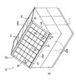
図1には、本発明の一実施形態に係る建物10が示されている。このユニット式建物10は、基礎11上に設置された複数の建物ユニット12Aで形成される建物本体12と、建物本体12の上部に形成された太陽電池屋根13とを備えている。
【0014】
建物ユニット12Aの各々は、工場で、床面材、壁材、その他の必要な設備部材を骨組みに取り付けた後、トラック等により建築現場に搬送され、建築現場において、互いに接合されてユニット式建物10を形成するものである。
建物ユニット12Aは、図2に示すように、四隅に立設される柱91と、これらの柱91の上端および下端間を相互に連結する天井小梁92および床梁93とを直方体状に組んだ骨組み90を有したものである。
ユニット式建物10は、このような建物ユニット12Aで形成することにより、建築現場における現場作業が著しく軽減可能とされ、建築工期の大幅な短縮が図れるようになっている。
【0015】
太陽電池屋根13は、棟の両側に傾斜面が形成された切り妻状の屋根であり、複数の屋根パネル14と、屋根材となる複数の太陽エネルギー利用パネルである太陽電池パネル21と、棟に沿って取り付けられる棟カバー15と、切り妻屋根の妻側端縁に取り付けられるけらば部材16と、軒先13A端縁に沿って取り付けられる軒先部材17とを備えている。
【0016】
太陽電池パネル21は、複数の屋根パネル14によって形成される屋根面14Aに、その傾斜面に沿って上下左右に配列されている。
各太陽電池パネル21は、図3に示すように、太陽光で発電を行う所定枚数のソーラーセルを収めた平板状の完全防水ケース22と、このケース22の周りを囲む四角枠状のフレーム23とを備えている。
フレーム23は、屋根13の傾斜方向に沿って左右に配置される2本の縦枠部24と、これら縦枠部24の上下端を接続し、かつ、屋根13の桁方向に沿って配置されている上枠部25および下枠部26とを備えて形成されている。
これらの縦枠部24、上枠部25および下枠部26によって、太陽電池パネル21全体の防水および補強がなされ、内部のソーラーセルが、雨水による漏電や短絡等の事故および太陽電池パネル21の表面に加わる荷重等から保護されるようになっている。
【0017】
このような太陽電池パネル21は、図4に示すように、左右の縦枠部24が屋根13の傾斜方向に沿って野地板14B上に取り付けられた一対のレール状の支持用レール部材31に固定されている。
支持用レール部材31は、太陽電池パネル21の縦枠部24を受けるパネル受部32と、このパネル受部32を支持し、屋根面14Aの野地板14B上にビス80で固定されるパネル支持部33とから形成されている。
また、各太陽電池パネル21間には、隙間を覆うカバー材41が設けられている。
パネル受部32には、例えばビス80等で太陽電池パネル21の縦枠部24が固定されているとともに、パネル受部32の長手方向に沿った両端には、太陽電池パネル21とカバー材41との間から万が一浸入してきた雨水等が野地板14B上に落ちることを防ぐ止水部32Aが形成されている。
また、パネル支持部33は、その内部が中空の樋状に形成されている。
【0018】
仮にカバー材41と縦枠部24との間から浸入する雨水等の水は、パネル受部32の上面を伝って軒先13Aから排出されるようになっている。
縦枠部24をパネル受部32に固定するビス80の孔を伝ってパネル支持部33の内部に浸入した雨水等の水は、パネル支持部33を通して軒先13Aから排出できるようになっている。
ここで、野地板14Bは、合板等の面材であり、表面にアスファルトルーフィング等のシート材14Cが貼り付けられている。
【0019】
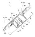
また、上下に配列された太陽電池パネル21A、21B間の接合構造は、図5に示すように、下方に配置された太陽電池パネル21Bの上枠部25は、断面口形の本体51と、この本体51の下部から外側(斜め上側)へ向けて設けられた断面L字形の当接片52とを備えてアルミの押出成形により一体形成された長尺部材で構成されている。
本体51の端部と当接片52とによって、上方が開口された溝形の樋部53が形成されている。
【0020】
上方に配置された太陽電池パネル21Aの下枠部26は、断面略口形の本体61と、この本体61の側面上部から外側(斜め下側)に向かって水平に突出した平板状のつば部62と、このつば部62の下面に突設された水切り部63と、この水切り部63の中間部分と本体61の側面とを連結する中間連結部64とを備えてアルミの押出成形により一体形成された長尺部材である。
ここで、水切り部63の長さ寸法は、後述する面戸を塞ぐ面戸部材70が取付可能な大きさとなっている。
また、つば部62の先端下面には、下方に突出する突起部62Aが一体に形成されている。この際、上方に配置された太陽電池パネル21Aの下枠部26の水切り部63の先端は、下方に配置された太陽電池パネル21Bの上枠部25の樋部53の開口と対向する位置に設けられている。
【0021】
さらに、上枠部25の当接片52の側面と、下枠部26の本体61の側面とは、シール部材42を介して互いに密着されている。
上方に配置された太陽電池パネル21Aのつば部62は、下方に配置された太陽電池パネル21Bの切欠部54に載置されている。
ここで、樋部53に雨水等が溜まっても、中間連結部64によって下枠部26の内部に雨水等が浸入しないようになっている。
なお、他の上下に配列された太陽電池パネル間、例えば、太陽電池パネル21A、21C間の接合構造も同様な構造となっている。
【0022】
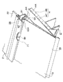
屋根面14Aに上下に配列された太陽電池パネル21のうち、最下位置となる軒先13Aに面する太陽電池パネル21の下枠部26には、図6、7に示すように当該下枠部26から軒先13Aまで延びるとともに、太陽電池パネル21が取り付けられない余白部分である面戸を覆う面戸部材70が設けられている。
面戸部材70は、下枠部26に取り付けられる取付部71と、面戸を覆う被覆部72とを備えて、軒先13Aに沿って長尺状に形成されており、取付部71は、下枠部26の水切り部63の側面にビス80等で取り付けられている。
この面戸部材70を取り付ける下枠部26は、前述した上下に配列された太陽電池パネル21のうちの上方に配置された太陽電池パネル21Aの下枠部26と同一形状の下枠部26が利用されている。
【0023】
太陽電池屋根13は、次のように形成される。
まず、工場において、支持用レール部材31や太陽電池パネル21、面戸部材70等を製造し、建築現場に搬送する。
現場では、屋根面14Aに支持用レール部材31を屋根13の傾斜方向に沿って上下に複数配置し、これらの支持用レール部材31の上に太陽電池パネル21の両端縁(縦枠部24)を支持させて配置する。このようにして、太陽電池パネル21を屋根面14Aに上下左右に配列し、太陽電池屋根13を形成する。
全ての太陽電池パネル21が配置されたら、軒先13Aに面する太陽電池パネル21の下枠部26の水切り部63に面戸部材70を設ける。
【0024】
ここで、太陽電池パネル21は、下方から配置し、その後上方を配置する。下方に配置された太陽電池パネル21Bに対して上方に配置された太陽電池パネル21Aを押しつけることにより、上方に配置された太陽電池パネル21Aのつば部62が下方に配置された太陽電池パネル21Bの切欠部54に当接して両太陽電池パネル21同士の位置決めが行われる。
この際、太陽電池パネル21のフレーム23の形状は同一形状となっているので、配置位置を考慮する必要がなく、下方から順番に配置していけばよい。なお、面戸部材70は、予め太陽電池パネル21に取り付けておいてもよい。
【0025】
このような本実施形態によれば、次のような効果が得られる。
すなわち、水切り部63の基端部分をつば部62に連結し、中間部分を中間連結部64に連結したので、従来のように、つば部を単に突設していた場合に比べて、同じ厚さでも水切り部63の剛性が大きくなり、これにより、水切り部63の長さ寸法を大きくしても変形することがなく、水切り部63の長さ寸法は、面戸を塞ぐ面戸部材70が取付可能となる寸法まで拡張することができる。
このため、面戸部材70を取り付けるにあたり、下枠部26の水切り部63を切り取る作業が不要となる上、水切り部63が省略された専用の下枠部26を用意する必要がなく、下枠部26の形状が統一されるようになり、フレーム23の製造効率を損なうことなく、設置作業が容易に行うことができる。
【0026】
また、下枠部26は、本体61と、つば部62と、水切り部63と、中間連結部64とを備えてアルミの押出成形により一体形成されているので、別体の部品を組み合わせて形成するよりも、簡単に製造することができるとともに、長さ寸法を充分確保でき、かつ、変形しにくい水切り部63を確実に得ることができる。
【0027】
さらに、下方に配置された太陽電池パネル21Bの樋部53の開口と、上方に配置された太陽電池パネル21Aの水切り部63の先端とが対向しているため、上方に配置された太陽電池パネル21Aの下枠部26のつば部62と、下方に配置された太陽電池パネル21Bの上枠部25との隙間から雨水が浸入しても、その雨水は水切り部63によって樋部53に導入され、屋根13の防水を充分に確保できる。
【0028】
また、太陽電池屋根13を屋根パネル14によって形成することによって、建物本体12と同様に、建築現場における屋根面形成のための現場作業を著しく軽減することができるので、ユニット式建物10の屋根に太陽電池屋根13を適用しても、建築現場における現場作業が著しく軽減可能とされ、建築工期の大幅な短縮を図ることができる。
【0029】
なお、本発明は前記実施の形態に限定されるものではなく、本発明の目的を達成できる他の構成等を含み、以下に示すような変形等も本発明に含まれる。
例えば、上方に配置された太陽電池パネル21Aの水切り部63の先端の位置としては、下方に配置された太陽電池パネル21Bの樋部53の開口と対向する位置に限らず、水切り部63によって雨水が樋部53に落とされる位置に水切り部63があればよい。
【0030】
また、前記実施形態では、太陽電池パネルについて説明したが、太陽エネルギー利用パネルとしてはこれに限らず、例えば、内部に流水する水を太陽熱で熱して温水とする太陽熱コレクタ等でもよい。
【0031】
さらに、前記実施形態では、下枠部26は、本体61と、つば部62と、水切り部63と、中間連結部64とが一体に形成されていたが、これに限らず、例えば、別々に形成した本体、つば部、水切り部および中間連結部を組み合わせて下枠部26を形成してもよい。
【0032】
また、建物としては、箱状に形成された建物ユニットを複数組み合わせたユニット式建物に限らず、板状に形成された壁パネルおよび床パネルを複数組み合わせたパネル方式のプレハブ建物や、柱および梁等の軸組材を建築現場で接合する在来工法による建物でもよい。
【0033】
【発明の効果】
以上に述べたように、本発明の太陽エネルギー利用パネルおよび太陽エネルギー利用屋根によれば、フレームの製造効率を損なうことなく、設置作業を容易に行うことができるという効果がある。
【図面の簡単な説明】
【図1】本発明の一実施形態におけるユニット式建物を示す斜視図である。
【図2】前記実施形態における建物ユニットの骨組みを示す斜視図である。
【図3】前記実施形態における太陽電池パネルを示す斜視図である。
【図4】図1におけるIV−IV線に沿った断面図である。
【図5】図1におけるV−V線に沿った断面図である。
【図6】図1におけるVI−VI線に沿った断面図である。
【図7】前記実施形態における軒先部分の拡大図である。
【符号の説明】
13 太陽エネルギー利用屋根である太陽電池屋根
21 太陽エネルギー利用パネルとしての太陽電池パネル
22 防水ケース
23 フレーム
25 上枠部
26 下枠部
53 樋部
62 つば部
63 水切り部
64 中間連結部[0001]
BACKGROUND OF THE INVENTION
The present invention relates to a solar energy utilization panel and a solar energy utilization roof provided along an inclined surface of a roof.
[0002]
[Background]
Conventionally, there are solar energy utilization panels such as a solar cell panel that converts sunlight into electricity and uses it as solar energy, and a solar heat collector that collects solar heat (radiant heat) and uses it as hot water. A solar energy utilization roof is configured by installing a plurality of such panels on the top, bottom, left, and right along an inclined surface of a roof such as a house.
[0003]
Of these, when installing solar panels on the roof, in order to prevent accidents such as leakage due to water, a predetermined number of solar cells, which are solar cells, are placed inside a flat, completely waterproof case. A square frame-shaped frame is provided around the case, and this frame is attached to the roof. Such a mounting structure can also be applied to solar collectors.
[0004]
In order to arrange such solar energy utilization panels up and down on the slope of the roof, it is necessary to improve drainage of the roof surface and ensure its waterproof performance. For this purpose, a frame is provided on the upper frame part of the frame, a draining part is provided on the lower frame part, and the other solar energy utilization panel disposed above the collar part of the solar energy utilization panel disposed below. Even if rainwater or the like enters the gaps between these solar energy panels, a drainer is arranged and water such as rainwater is guided to the buttocks by the drainer to promote drainage. Thereby, waterproof performance is ensured (refer Unexamined-Japanese-Patent No. 10-169127 etc.).
Here, if the draining portion extends long downward, the draining portion is likely to be deformed during the installation work of the solar energy utilization panel, and if it is deformed, it takes time to correct and prolongs the mounting operation. The extension dimension is set to a minimum.
[0005]
In addition, among the solar energy utilization panels arranged in the vertical direction on the sloped roof surface, the lower frame part of the solar energy utilization panel that is the lowest position extends from the lower frame part to the eaves, and uses solar energy. A face door plate is provided to cover a blank portion where the panel cannot be attached.
[0006]
[Problems to be solved by the invention]
In such a solar energy utilization panel, since the length dimension of the draining portion is minimized, there is no room for attaching the face door plate in the draining portion. There is a problem that a face door plate must be attached to the frame part, and the work of cutting off the draining part becomes cumbersome and it takes time to install the solar energy utilization panel.
On the other hand, it is conceivable to prepare a dedicated lower frame part in which the draining part is omitted in order to attach the face door plate, but there is a problem that the type of the lower frame part increases and the manufacturing efficiency of the frame is impaired. is there.
[0007]
An object of the present invention is to provide a solar energy utilization panel and a solar energy utilization roof that can be easily installed without impairing the manufacturing efficiency of the frame.
[0008]
[Means for Solving the Problems]
Referring to the drawings, the first invention of the present invention is a solar energy utilization panel (for example, a solar cell panel 21) having a square frame-
In the present invention, since the base end portion of the draining portion is connected to the flange portion, and the intermediate portion is connected to the intermediate connection portion, compared to a case where the flange portion is simply provided as in the prior art, Even if the thickness is the same, the rigidity of the draining portion increases, so that even if the length dimension of the draining portion is increased, the drainage portion will not be deformed, and the length dimension of the draining portion can be attached to a face door plate that closes the face door. It becomes possible to expand to the dimension which becomes.
For this reason, when attaching the face door plate, it is not necessary to cut off the draining part of the lower frame part, and it is not necessary to prepare a dedicated lower frame part in which the draining part is omitted, and the shape of the lower frame part is unified. Thus, the installation work can be easily performed without deteriorating the manufacturing efficiency of the frame.
[0009]
In the above, it is preferable that the
Such a lower frame portion can be easily manufactured by extrusion molding or the like, and a draining portion that has a sufficient length dimension and is difficult to deform can be obtained with certainty.
[0010]
Furthermore, the solar energy utilization panel is desirably a
Thus, if the present invention is applied to a large number of solar cell panels installed on the roof, the manufacturing efficiency of the frame is not impaired when manufacturing the frame in large quantities, and the productivity is improved.
[0011]
The second aspect of the present invention, when described with reference to the drawings, is characterized in that a plurality of the solar energy utilization panels described above are arranged vertically along the inclined surface of the
In the present invention, when the solar energy utilization panel is arranged on the roof, the shape of the lower frame part forming the frame of the solar energy utilization panel is the same, so it is not necessary to consider the arrangement position of the solar energy utilization panel, The mounting of the face door member is also simplified, and the installation work can be easily performed.
[0012]
Moreover, as for the solar
Thus, if it arrange | positions so that the opening of a collar part and the front-end | tip of a draining part may face, the collar part of the lower frame part of the solar energy utilization panel arrange | positioned upward, and the solar energy arrange | positioned below Even if rainwater enters from the gap with the upper frame part of the use panel, the rainwater is introduced into the heel by the drainage part, and the roof is sufficiently waterproof.
[0013]
DETAILED DESCRIPTION OF THE INVENTION
Embodiments of the present invention will be described below with reference to the drawings.
FIG. 1 shows a
[0014]
Each of the
As shown in FIG. 2, the
By forming the
[0015]
The
[0016]
The
As shown in FIG. 3, each
The
The
[0017]
As shown in FIG. 4, such a
The
Further, a
For example, the
Further, the
[0018]
Temporarily, water such as rainwater entering from between the
Water such as rain water that has entered the inside of the
Here, the
[0019]
Further, as shown in FIG. 5, the
The end portion of the
[0020]
The
Here, the length dimension of the draining
In addition, a
[0021]
Further, the side surface of the
The
Here, even if rainwater or the like accumulates in the
In addition, the junction structure between the solar cell panels arranged on the other upper and lower sides, for example, between the solar cell panels 21A and 21C has a similar structure.
[0022]
Among the
The
The
[0023]
The
First, in the factory, the
At the site, a plurality of
When all the
[0024]
Here, the
At this time, since the shape of the
[0025]
According to this embodiment, the following effects can be obtained.
That is, since the base end portion of the draining
For this reason, when attaching the
[0026]
In addition, the
[0027]
Furthermore, since the opening of the
[0028]
Further, by forming the
[0029]
In addition, this invention is not limited to the said embodiment, Other structures etc. which can achieve the objective of this invention are included, The deformation | transformation etc. which are shown below are also contained in this invention.
For example, the position of the tip of the draining
[0030]
Moreover, in the said embodiment, although the solar cell panel was demonstrated, it is not restricted to this as a solar energy utilization panel, For example, the solar-heat collector etc. which heat the water which flows into an inside with solar heat and make it warm water etc. may be sufficient.
[0031]
Furthermore, in the said embodiment, although the
[0032]
In addition, the building is not limited to a unit type building in which a plurality of building units formed in a box shape are combined, but a panel type prefab building in which a plurality of wall panels and floor panels formed in a plate shape are combined, columns and beams. The building by the conventional construction method which joins frame members, such as, at a construction site may be sufficient.
[0033]
【The invention's effect】
As described above, according to the solar energy utilization panel and the solar energy utilization roof of the present invention, there is an effect that the installation work can be easily performed without impairing the manufacturing efficiency of the frame.
[Brief description of the drawings]
FIG. 1 is a perspective view showing a unit building in an embodiment of the present invention.
FIG. 2 is a perspective view showing a framework of a building unit in the embodiment.
FIG. 3 is a perspective view showing a solar cell panel in the embodiment.
4 is a cross-sectional view taken along line IV-IV in FIG.
5 is a cross-sectional view taken along line VV in FIG. 1. FIG.
6 is a cross-sectional view taken along line VI-VI in FIG.
FIG. 7 is an enlarged view of an eaves portion in the embodiment.
[Explanation of symbols]
13
Claims (4)
前記水切り部には面戸が取り付けられることを特徴とする太陽エネルギー利用パネル。In the solar energy utilization panel according to claim 1,
A solar energy utilization panel, wherein a face door is attached to the draining portion.
Priority Applications (1)
| Application Number | Priority Date | Filing Date | Title |
|---|---|---|---|
| JP26312698A JP4174107B2 (en) | 1998-09-17 | 1998-09-17 | Solar energy panels and solar energy roofs |
Applications Claiming Priority (1)
| Application Number | Priority Date | Filing Date | Title |
|---|---|---|---|
| JP26312698A JP4174107B2 (en) | 1998-09-17 | 1998-09-17 | Solar energy panels and solar energy roofs |
Publications (2)
| Publication Number | Publication Date |
|---|---|
| JP2000096792A JP2000096792A (en) | 2000-04-04 |
| JP4174107B2 true JP4174107B2 (en) | 2008-10-29 |
Family
ID=17385191
Family Applications (1)
| Application Number | Title | Priority Date | Filing Date |
|---|---|---|---|
| JP26312698A Expired - Fee Related JP4174107B2 (en) | 1998-09-17 | 1998-09-17 | Solar energy panels and solar energy roofs |
Country Status (1)
| Country | Link |
|---|---|
| JP (1) | JP4174107B2 (en) |
Cited By (1)
| Publication number | Priority date | Publication date | Assignee | Title |
|---|---|---|---|---|
| JP2014221989A (en) * | 2013-05-14 | 2014-11-27 | 株式会社吉岡 | Installation structure for photovoltaic module |
Families Citing this family (10)
| Publication number | Priority date | Publication date | Assignee | Title |
|---|---|---|---|---|
| CN102354717B (en) * | 2009-04-29 | 2014-03-19 | 无锡尚德太阳能电力有限公司 | Solar module mounting system |
| CN102556316A (en) * | 2010-12-14 | 2012-07-11 | 无锡尚德太阳能电力有限公司 | Mounting device and photovoltaic power generation sail system provided with same |
| JP2013072204A (en) * | 2011-09-27 | 2013-04-22 | Toshiba Corp | Roof building material |
| JP2013076305A (en) * | 2011-09-30 | 2013-04-25 | Lixil Corp | Photovoltaic power generation device and installation method thereof |
| CN102881738A (en) * | 2012-08-08 | 2013-01-16 | 泰通(泰州)工业有限公司 | Solar photovoltaic component frame |
| JP6193061B2 (en) * | 2013-09-03 | 2017-09-06 | 積水化学工業株式会社 | Snow retaining member and solar cell roof structure |
| CN105262417A (en) * | 2015-10-28 | 2016-01-20 | 协鑫集成(上海)能源科技发展有限公司 | Photovoltaic module, photovoltaic array and photovoltaic roof system |
| CN108691392A (en) * | 2018-08-01 | 2018-10-23 | 江苏汉嘉薄膜太阳能科技有限公司 | Side retracting device, receipts edge system and photovoltaic tile system for photovoltaic tile |
| CN113595474B (en) * | 2021-09-29 | 2022-01-18 | 深圳市安泰科能源环保股份有限公司 | Frame construction, photovoltaic array and building of photovoltaic integration of photovoltaic array |
| CN114961126B (en) * | 2022-03-30 | 2024-03-29 | 乐居乐筑(北京)新能源科技有限公司 | Photovoltaic roofing connection structure and contain its photovoltaic roofing |
-
1998
- 1998-09-17 JP JP26312698A patent/JP4174107B2/en not_active Expired - Fee Related
Cited By (1)
| Publication number | Priority date | Publication date | Assignee | Title |
|---|---|---|---|---|
| JP2014221989A (en) * | 2013-05-14 | 2014-11-27 | 株式会社吉岡 | Installation structure for photovoltaic module |
Also Published As
| Publication number | Publication date |
|---|---|
| JP2000096792A (en) | 2000-04-04 |
Similar Documents
| Publication | Publication Date | Title |
|---|---|---|
| KR20080009264A (en) | Roof cover or facade siding | |
| JP4174107B2 (en) | Solar energy panels and solar energy roofs | |
| JP2000027395A (en) | Solar-cell panel and mounting structure thereof | |
| JP5528398B2 (en) | Solar cell module | |
| JP2014227687A (en) | Roof structure of unit type building | |
| JPH11336210A (en) | Ventilation structure of solar power generation panel setting roof | |
| JP3269778B2 (en) | Roof structure | |
| CN217630881U (en) | Roof backboard and roof structure | |
| JP3871750B2 (en) | Solar energy converter | |
| JP2000154625A (en) | Solar cell loaded roof and assembly method thereof | |
| JP3618070B2 (en) | Roof with solar cells | |
| JP4074002B2 (en) | Roof with solar cell and method of assembling the same | |
| JP2013002071A (en) | Lower structure of solar cell panel and exterior structure including solar cell panel | |
| JP4121194B2 (en) | Installation structure of rain retainer | |
| JP2002371678A (en) | Roof tile with solar battery | |
| JP2002004527A (en) | Solar energy collecting device | |
| JP2631966B2 (en) | Roof panel and roof structure using roof panel | |
| JPH10317620A (en) | Ventilation construction for roof installing rooftop equipment such as solar cell module | |
| JP2001182262A (en) | Roof with solar battery | |
| CN218061063U (en) | Roof board | |
| JP5410252B2 (en) | Roof structure | |
| JP2000282649A (en) | Roof structure having solar energy conversion panel and its construction method | |
| JP2002038675A (en) | Roof with solar battery | |
| JP2596892B2 (en) | Roof panels, roof structures, and roof construction methods | |
| JP3163740U (en) | Installation structure of solar cell module |
Legal Events
| Date | Code | Title | Description |
|---|---|---|---|
| A621 | Written request for application examination |
Free format text: JAPANESE INTERMEDIATE CODE: A621 Effective date: 20050920 |
|
| RD02 | Notification of acceptance of power of attorney |
Free format text: JAPANESE INTERMEDIATE CODE: A7422 Effective date: 20070704 |
|
| RD02 | Notification of acceptance of power of attorney |
Free format text: JAPANESE INTERMEDIATE CODE: A7422 Effective date: 20070827 |
|
| A977 | Report on retrieval |
Free format text: JAPANESE INTERMEDIATE CODE: A971007 Effective date: 20071210 |
|
| A131 | Notification of reasons for refusal |
Free format text: JAPANESE INTERMEDIATE CODE: A131 Effective date: 20080108 |
|
| A711 | Notification of change in applicant |
Free format text: JAPANESE INTERMEDIATE CODE: A712 Effective date: 20080108 |
|
| RD04 | Notification of resignation of power of attorney |
Free format text: JAPANESE INTERMEDIATE CODE: A7424 Effective date: 20080131 |
|
| A521 | Request for written amendment filed |
Free format text: JAPANESE INTERMEDIATE CODE: A523 Effective date: 20080307 |
|
| A131 | Notification of reasons for refusal |
Free format text: JAPANESE INTERMEDIATE CODE: A131 Effective date: 20080408 |
|
| A521 | Request for written amendment filed |
Free format text: JAPANESE INTERMEDIATE CODE: A523 Effective date: 20080606 |
|
| TRDD | Decision of grant or rejection written | ||
| A01 | Written decision to grant a patent or to grant a registration (utility model) |
Free format text: JAPANESE INTERMEDIATE CODE: A01 Effective date: 20080805 |
|
| A01 | Written decision to grant a patent or to grant a registration (utility model) |
Free format text: JAPANESE INTERMEDIATE CODE: A01 |
|
| A61 | First payment of annual fees (during grant procedure) |
Free format text: JAPANESE INTERMEDIATE CODE: A61 Effective date: 20080818 |
|
| R150 | Certificate of patent or registration of utility model |
Free format text: JAPANESE INTERMEDIATE CODE: R150 |
|
| FPAY | Renewal fee payment (event date is renewal date of database) |
Free format text: PAYMENT UNTIL: 20110822 Year of fee payment: 3 |
|
| FPAY | Renewal fee payment (event date is renewal date of database) |
Free format text: PAYMENT UNTIL: 20110822 Year of fee payment: 3 |
|
| S533 | Written request for registration of change of name |
Free format text: JAPANESE INTERMEDIATE CODE: R313533 |
|
| FPAY | Renewal fee payment (event date is renewal date of database) |
Free format text: PAYMENT UNTIL: 20110822 Year of fee payment: 3 |
|
| R350 | Written notification of registration of transfer |
Free format text: JAPANESE INTERMEDIATE CODE: R350 |
|
| FPAY | Renewal fee payment (event date is renewal date of database) |
Free format text: PAYMENT UNTIL: 20110822 Year of fee payment: 3 |
|
| FPAY | Renewal fee payment (event date is renewal date of database) |
Free format text: PAYMENT UNTIL: 20140822 Year of fee payment: 6 |
|
| R250 | Receipt of annual fees |
Free format text: JAPANESE INTERMEDIATE CODE: R250 |
|
| R250 | Receipt of annual fees |
Free format text: JAPANESE INTERMEDIATE CODE: R250 |
|
| R250 | Receipt of annual fees |
Free format text: JAPANESE INTERMEDIATE CODE: R250 |
|
| R250 | Receipt of annual fees |
Free format text: JAPANESE INTERMEDIATE CODE: R250 |
|
| LAPS | Cancellation because of no payment of annual fees |