JP4173814B2 - Tools with helical coils for structured surface articles - Google Patents
Tools with helical coils for structured surface articles Download PDFInfo
- Publication number
- JP4173814B2 JP4173814B2 JP2003552521A JP2003552521A JP4173814B2 JP 4173814 B2 JP4173814 B2 JP 4173814B2 JP 2003552521 A JP2003552521 A JP 2003552521A JP 2003552521 A JP2003552521 A JP 2003552521A JP 4173814 B2 JP4173814 B2 JP 4173814B2
- Authority
- JP
- Japan
- Prior art keywords
- roll
- wire
- tool
- tool roll
- base roll
- Prior art date
- Legal status (The legal status is an assumption and is not a legal conclusion. Google has not performed a legal analysis and makes no representation as to the accuracy of the status listed.)
- Expired - Fee Related
Links
Images


Classifications
-
- B—PERFORMING OPERATIONS; TRANSPORTING
- B29—WORKING OF PLASTICS; WORKING OF SUBSTANCES IN A PLASTIC STATE IN GENERAL
- B29C—SHAPING OR JOINING OF PLASTICS; SHAPING OF MATERIAL IN A PLASTIC STATE, NOT OTHERWISE PROVIDED FOR; AFTER-TREATMENT OF THE SHAPED PRODUCTS, e.g. REPAIRING
- B29C59/00—Surface shaping of articles, e.g. embossing; Apparatus therefor
- B29C59/02—Surface shaping of articles, e.g. embossing; Apparatus therefor by mechanical means, e.g. pressing
-
- B—PERFORMING OPERATIONS; TRANSPORTING
- B29—WORKING OF PLASTICS; WORKING OF SUBSTANCES IN A PLASTIC STATE IN GENERAL
- B29C—SHAPING OR JOINING OF PLASTICS; SHAPING OF MATERIAL IN A PLASTIC STATE, NOT OTHERWISE PROVIDED FOR; AFTER-TREATMENT OF THE SHAPED PRODUCTS, e.g. REPAIRING
- B29C59/00—Surface shaping of articles, e.g. embossing; Apparatus therefor
- B29C59/002—Component parts, details or accessories; Auxiliary operations
-
- B—PERFORMING OPERATIONS; TRANSPORTING
- B29—WORKING OF PLASTICS; WORKING OF SUBSTANCES IN A PLASTIC STATE IN GENERAL
- B29C—SHAPING OR JOINING OF PLASTICS; SHAPING OF MATERIAL IN A PLASTIC STATE, NOT OTHERWISE PROVIDED FOR; AFTER-TREATMENT OF THE SHAPED PRODUCTS, e.g. REPAIRING
- B29C43/00—Compression moulding, i.e. applying external pressure to flow the moulding material; Apparatus therefor
- B29C43/22—Compression moulding, i.e. applying external pressure to flow the moulding material; Apparatus therefor of articles of indefinite length
- B29C43/24—Calendering
-
- B—PERFORMING OPERATIONS; TRANSPORTING
- B29—WORKING OF PLASTICS; WORKING OF SUBSTANCES IN A PLASTIC STATE IN GENERAL
- B29C—SHAPING OR JOINING OF PLASTICS; SHAPING OF MATERIAL IN A PLASTIC STATE, NOT OTHERWISE PROVIDED FOR; AFTER-TREATMENT OF THE SHAPED PRODUCTS, e.g. REPAIRING
- B29C59/00—Surface shaping of articles, e.g. embossing; Apparatus therefor
- B29C59/02—Surface shaping of articles, e.g. embossing; Apparatus therefor by mechanical means, e.g. pressing
- B29C59/022—Surface shaping of articles, e.g. embossing; Apparatus therefor by mechanical means, e.g. pressing characterised by the disposition or the configuration, e.g. dimensions, of the embossments or the shaping tools therefor
- B29C59/025—Fibrous surfaces with piles or similar fibres substantially perpendicular to the surface
-
- B—PERFORMING OPERATIONS; TRANSPORTING
- B29—WORKING OF PLASTICS; WORKING OF SUBSTANCES IN A PLASTIC STATE IN GENERAL
- B29C—SHAPING OR JOINING OF PLASTICS; SHAPING OF MATERIAL IN A PLASTIC STATE, NOT OTHERWISE PROVIDED FOR; AFTER-TREATMENT OF THE SHAPED PRODUCTS, e.g. REPAIRING
- B29C59/00—Surface shaping of articles, e.g. embossing; Apparatus therefor
- B29C59/02—Surface shaping of articles, e.g. embossing; Apparatus therefor by mechanical means, e.g. pressing
- B29C59/04—Surface shaping of articles, e.g. embossing; Apparatus therefor by mechanical means, e.g. pressing using rollers or endless belts
Abstract
Description
本発明は、構造化表面を備えた物品を製造する分野に関する。より詳細には、本発明は、1以上の構造化表面を備えた物品を製造するための波形螺旋コイルを備えた工具類、およびその工具類を使用して1以上の構造化表面を備えた物品を製造する方法を提供する。 The present invention relates to the field of manufacturing articles with structured surfaces. More particularly, the present invention comprises tools with corrugated helical coils for producing articles with one or more structured surfaces, and one or more structured surfaces using the tools. A method of manufacturing an article is provided.
1以上の構造化表面を備えた物品には、さまざまな用途がある。これらの物品は、たとえば、増加した表面積、機械的ファスナを提供するために使用される構造、光学特性などを示すフィルムとして提供することができる。これらのフィルムを、機械的ファスナとして使用するために製造する場合、構造化表面上に見出される突出部は、通常、フックと呼ばれる。フックは、湾曲形状に形成してもよいし、たとえばキノコ形状のヘッドを含むように、後の作業で変形される、ほぼ直立したステムであってもよい。 Articles with one or more structured surfaces have a variety of uses. These articles can be provided, for example, as films that exhibit increased surface area, structure used to provide mechanical fasteners, optical properties, and the like. When these films are manufactured for use as mechanical fasteners, the protrusions found on the structured surface are usually referred to as hooks. The hook may be formed in a curved shape or may be a substantially upright stem that is deformed in a later operation to include, for example, a mushroom-shaped head.
機械的ファスナは、2つのフックストリップを、各ストリップを物品の一方に接着し、次に、2つのストリップを相互に係合させることによって2つの物品をともに締結するために使用することができるように設計されることがある。そのような機械的ファスナは、米国特許第3,192,589号明細書(ピアソン(Pearson))に示されており、この特許では、そのファスナを「両性」と呼び、というのは、そのヘッド付スタッドが、相互に噛合ったときに雄および雌の特徴の両方を有するからである。ピアソンのファスナは、一体的な、ヘッドのないスタッドが突出するベースを成形し、次に、スタッドの先端を熱で軟化させることによって、製造することができる。 A mechanical fastener can be used to fasten two hook strips together, by bonding each strip to one of the articles and then engaging the two strips together. May be designed. Such a mechanical fastener is shown in U.S. Pat. No. 3,192,589 (Pearson), where the fastener is referred to as “amphoteric” because its head This is because the studs have both male and female characteristics when interdigitated. Pearson fasteners can be manufactured by molding a base from which an integral, headless stud projects and then softening the tip of the stud with heat.
米国特許第5,077,870号明細書(メルビー(Melbye)ら)は、溶融材料を、移動するモールド面に形成されたキャビティに押込むことによって、機械的ファスナのフックストリップ部分を製造する1つの方法を開示している。次に、移動するモールド面によって形成されたステムをキャップして、所望のファスナを形成する。キャビティは、ドリリングによってモールド面に形成される。その結果、キャビティの形状は円筒形であり、深さ、直径、およびキャビティの間隔にいくらかの精度を得ることができるが、いくらかの困難および増加したコストを伴って得られる。さらに、モールド面の損傷は、典型的には、モールド全体を捨てることを必要とする。 US Pat. No. 5,077,870 (Melby et al.) Manufactures a hook strip portion of a mechanical fastener by pushing molten material into a cavity formed in a moving mold surface. One method is disclosed. Next, the desired fastener is formed by capping the stem formed by the moving mold surface. The cavity is formed on the mold surface by drilling. As a result, the cavity shape is cylindrical and some accuracy in depth, diameter, and cavity spacing can be obtained, but with some difficulty and increased cost. Furthermore, damage to the mold surface typically requires that the entire mold be discarded.
米国特許第5,792,411号明細書(モリス(Morris)ら)は、モールド面をレーザ加工することによって製造された成形工具を開示している。次に、溶融材料を、移動するモールド面のキャビティに押込み、ステムを形成する。次に、ステムをキャップして、所望のファスナを形成する。キャビティがレーザアブレーションによって形成されるので、キャビティ形状は、キャビティを形成するのに使用されるレーザビーム内のエネルギー分布に基いている。さらに、モールドを構成するのに使用される材料、レーザビームのパワー、ビーム内のエネルギー分布、ビームの焦点などの可変性によって、キャビティの深さの精密な制御を得るのが困難である。 US Pat. No. 5,792,411 (Morris et al.) Discloses a forming tool made by laser machining a mold surface. Next, the molten material is pushed into the cavity of the moving mold surface to form a stem. The stem is then capped to form the desired fastener. Since the cavity is formed by laser ablation, the cavity shape is based on the energy distribution in the laser beam used to form the cavity. Furthermore, it is difficult to obtain precise control of the cavity depth due to variability such as the material used to construct the mold, the power of the laser beam, the energy distribution within the beam, the focus of the beam, and the like.
米国特許第4,775,310号明細書(フィッシャー(Fischer))および国際公開第97/46129号パンフレット(レーシー(Lacey)ら)は、フックアンドループ式機械的ファスナ用フックストリップを製造するのに使用される工具類を開示している。これらの工具は、水冷ジャケットを備えた中空ドラムによって形成される。一連のモールドディスクまたは交互のモールドディスクおよびスペーサプレートを、ドラムの長さに沿ってともに積層して、ロール面上に所望のモールドキャビティを形成する。これらの設計の欠点としては、モールドキャビティが、同じ深さ、長さ、間隔などであることを確実にするために、適切な精度を有するモールドディスクを製造するコストが挙げられる。製造の困難さによってディスクに課されたサイズ制限は、工具を使用するプロセスの線速度を制限することがある。この設計の他の欠点としては、モールドキャビティの不均一な冷却、積重ねられたプレートによって製造された製品の不均一性などが挙げられる。 U.S. Pat. No. 4,775,310 (Fischer) and WO 97/46129 (Lacey et al.) Describe the manufacture of hook strips for hook and loop mechanical fasteners. Disclosed are the tools used. These tools are formed by a hollow drum with a water cooling jacket. A series of mold disks or alternating mold disks and spacer plates are laminated together along the length of the drum to form the desired mold cavity on the roll surface. Disadvantages of these designs include the cost of producing a mold disk with adequate precision to ensure that the mold cavities are the same depth, length, spacing, etc. The size limitations imposed on the disk by manufacturing difficulties can limit the linear speed of the process using the tool. Other disadvantages of this design include non-uniform cooling of the mold cavities, non-uniformity of products produced by the stacked plates.
本発明は、工具ロール、および工具ロールを使用して1以上の構造化表面を備えた物品を製造する方法を提供する。工具ロールは、適切な粘度または成形性の材料と関連して使用されると、物品上に構造化表面を形成することができる外面を含む。工具は、ロール形態で製造されるので、有利に、連続製造プロセスで使用することができる。あるいは、本発明の工具ロールを使用して、別々の物品を処理してもよい。 The present invention provides a tool roll and a method of manufacturing an article with one or more structured surfaces using the tool roll. The tool roll includes an outer surface that can form a structured surface on the article when used in conjunction with a material of appropriate viscosity or formability. Since the tool is manufactured in roll form, it can advantageously be used in a continuous manufacturing process. Alternatively, separate articles may be processed using the tool roll of the present invention.
「構造化表面」とは、物品の表面が、平らなまたは他の滑らかな面からはずれることを意味する。たとえば、構造化表面は、機械的ファスナと関連して使用されるステムなどの、それから延在する突出部を含んでもよい。他の代替の構造化表面としては、連続溝または連続隆起部、細長い構造などが挙げられるが、これらに限定されない。 “Structured surface” means that the surface of the article deviates from a flat or other smooth surface. For example, the structured surface may include protrusions extending therefrom, such as stems used in conjunction with mechanical fasteners. Other alternative structured surfaces include, but are not limited to, continuous grooves or ridges, elongated structures, and the like.
本発明の工具ロールは、円筒形ベースロールから構成され、1以上の連続ワイヤで、波形螺旋パターンに巻付けられている。ワイヤは、本質的に、工具ロールを使用して処理される物品上に形成すべき構造化表面の逆である構造化表面を工具ロール上に形成するために使用される。一実施形態において、ベースロールの周りに巻かれたワイヤの少なくとも1つが、ベースロールの周りに巻かれると、工具ロールの外面上に複数のモールドキャビティを形成する、中に形成された複数の空隙を含んでもよい。あるいは、1以上の巻かれたワイヤを使用して、連続構造化表面、たとえば、1つまたは複数の連続溝を形成してもよい。 The tool roll of the present invention comprises a cylindrical base roll and is wound around a corrugated spiral pattern with one or more continuous wires. The wire is used to form a structured surface on the tool roll that is essentially the inverse of the structured surface to be formed on the article being processed using the tool roll. In one embodiment, a plurality of voids formed therein, wherein at least one of the wires wound around the base roll forms a plurality of mold cavities on the outer surface of the tool roll when wound around the base roll. May be included. Alternatively, one or more wound wires may be used to form a continuous structured surface, such as one or more continuous grooves.
本発明の工具ロールのワイヤによって形成された波形螺旋コイルは、ベースロールの長手方向軸線に直角な基準面と1つまたは複数のワイヤとの間の距離が、ベースロールの円周を1方向に移動するとき、少なくとも1回、順次、増加し、減少するようなプロファイルまたは形状を示す。その結果、ベースロールの回りに巻付けられた1つまたは複数のワイヤは、ロールの面を横切って進むが、所望の、変化する、基準面との間の距離をもたらすように波形になる。1つまたは複数のワイヤによって形成された波形螺旋パターンは、ベースロールの1つまたは複数の端部に近接した巻き面によってもたらしてもよい。 The corrugated helical coil formed by the wire of the tool roll of the present invention has a distance between a reference plane perpendicular to the longitudinal axis of the base roll and the one or more wires so that the circumference of the base roll is in one direction. When moving, it exhibits a profile or shape that increases and decreases sequentially at least once. As a result, the wire or wires wrapped around the base roll travel across the surface of the roll, but are corrugated to provide the desired, changing distance from the reference plane. The corrugated spiral pattern formed by the one or more wires may be provided by a winding surface proximate one or more ends of the base roll.
この波形螺旋巻き設計の利点としては、たとえば、作業中に工具ロールをバイアスするいかなる表面(たとえば、ニップロール)上の磨耗の分布がより均一なことが挙げられるであろう。別の可能な利点は、1つまたは複数の巻かれたワイヤによって工具ロールに形成されるいかなるモールドキャビティの配向(機械方向に対して)も変えることに見出されるであろう。その場合、モールドキャビティによって構造物品に形成されるいかなる突出部も、機械方向に対して配向が変わってもよい。本発明の工具ロール上の波形螺旋巻きのさらに別の可能な利点は、ベースロールに対する巻線の回転を抑制できることである。 The advantages of this corrugated spiral design may include, for example, a more uniform distribution of wear on any surface (eg, nip roll) that biases the tool roll during operation. Another possible advantage will be found in changing the orientation (relative to the machine direction) of any mold cavity formed in the tool roll by one or more wound wires. In that case, any protrusion formed on the structural article by the mold cavity may change orientation relative to the machine direction. Yet another possible advantage of the corrugated spiral winding on the tool roll of the present invention is that the rotation of the winding relative to the base roll can be suppressed.
工具ロールの他の利点としては、工具ロールの外面が損傷または磨耗した場合、ベースロール上のワイヤ巻線を取替えることができることが挙げられるが、これに限定されない。工具ロールは、また、たとえば、積重ねられたプレート、またはモールド面の直接ドリリングを用いて工具ロールを製造するコストと比較して、比較的安価であることができる。 Other advantages of the tool roll include, but are not limited to, the wire winding on the base roll can be replaced if the outer surface of the tool roll is damaged or worn. The tool roll can also be relatively inexpensive compared to the cost of manufacturing the tool roll using, for example, stacked plates, or direct drilling of the mold surface.
別の利点は、ベースロールの周りに巻付けられる1つまたは複数のワイヤの厚さを変えることによって、ロールの幅に沿ったモールドキャビティの間隔を制御することができることである。円周のモールドキャビティの間隔も、ベースロールの周りに巻付けられる1つまたは複数のワイヤの空隙の間隔を制御することによって、独立して制御することができる。さらなる利点は、1つまたは複数のワイヤのプロファイルまたは断面形状、およびワイヤに形成される空隙の1つまたは複数の形状を制御することによって、モールドキャビティの1つまたは複数の形状の変化も得られることである。 Another advantage is that the spacing of the mold cavities along the width of the roll can be controlled by varying the thickness of one or more wires wound around the base roll. The spacing of the circumferential mold cavities can also be controlled independently by controlling the spacing of one or more wire voids wound around the base roll. A further advantage is that by controlling the profile or cross-sectional shape of one or more wires and the shape or shapes of the voids formed in the wire, one or more changes in the shape of the mold cavity can also be obtained. That is.
本発明のさらに別の利点は、ベースロールの熱質量と比較して、ベースロールの周りに巻付けられる1つまたは複数のワイヤの熱質量が比較的小さいことである。その結果、モールドキャビティの熱制御を向上させることができ、これは、工具ロールを使用して製造される製品の均一性の対応する向上をもたらすことができる。 Yet another advantage of the present invention is that the thermal mass of one or more wires wound around the base roll is relatively small compared to the thermal mass of the base roll. As a result, thermal control of the mold cavities can be improved, which can lead to a corresponding improvement in the uniformity of products manufactured using tool rolls.
本発明と関連して使用されるように、「モールドキャビティ」は、成形プロセス中に成形可能な材料が流れることができる、それがなければ滑らかなまたは平らな面のいかなる不連続であってもよい。本発明のいくつかの実施形態において、工具ロールは、以下で定義されるような高アスペクト比を有するモールドキャビティを含んでもよいが、モールドキャビティが高アスペクト比を有さなくてもよいことが理解されるべきである。 As used in connection with the present invention, a “mold cavity” is any discontinuity of a smooth or flat surface that allows moldable material to flow during the molding process. Good. In some embodiments of the present invention, the tool roll may include a mold cavity having a high aspect ratio as defined below, but it is understood that the mold cavity may not have a high aspect ratio. It should be.
一態様において、本発明は、長手方向軸線に沿って隔置された第1および第2端部を有する円筒形ベースロールと、中に形成された複数の第1空隙を備え、ベースロールの周りに螺旋コイルに巻かれた第1ワイヤとを含む工具ロールであって、第1ワイヤの複数の第1空隙が、複数の第1キャビティを形成し、複数の第1キャビティの各キャビティが、工具ロールの外面に開口部を含み、第1ワイヤとベースロールの長手方向軸線に直角な基準面との間の距離が、ベースロールの円周を1方向に移動するとき、少なくとも1回、順次、増加し、減少する、工具ロールを提供する。 In one aspect, the present invention comprises a cylindrical base roll having first and second ends spaced along a longitudinal axis, and a plurality of first voids formed therein, around the base roll And a first wire wound around a spiral coil, wherein a plurality of first cavities of the first wire form a plurality of first cavities, and each cavity of the plurality of first cavities is a tool roll. When the distance between the first wire and the reference plane perpendicular to the longitudinal axis of the base roll includes an opening in the outer surface of the roll and moves in one direction along the circumference of the base roll, at least once, sequentially, Provides a tool roll that increases and decreases.
別の態様において、本発明は、長手方向軸線に沿って隔置された第1および第2端部を有する円筒形ベースロールと、中に形成された複数の第1空隙を備え、ベースロールの周りに螺旋コイルに巻かれた第1ワイヤと、ベースロールの周りに巻かれた第2ワイヤとを含む工具ロールであって、第2ワイヤが、第1ワイヤの隣接した螺旋コイル間に配置され、第2ワイヤと、第1ワイヤの複数の第1空隙とが、複数の第1キャビティを形成し、複数の第1キャビティの各キャビティが、工具ロールの外面に開口部を含み、第1ワイヤとベースロールの長手方向軸線に直角な基準面との間の距離が、ベースロールの円周を1方向に移動するとき、少なくとも1回、順次、増加し、減少する、工具ロールを提供する。 In another aspect, the invention comprises a cylindrical base roll having first and second ends spaced along a longitudinal axis, and a plurality of first voids formed therein, A tool roll including a first wire wound around a helical coil and a second wire wound around a base roll, wherein the second wire is disposed between adjacent helical coils of the first wire. The second wire and the plurality of first gaps of the first wire form a plurality of first cavities, each cavity of the plurality of first cavities including an opening on the outer surface of the tool roll, A tool roll is provided in which the distance between the base plane and a reference plane perpendicular to the longitudinal axis of the base roll increases and decreases sequentially at least once as the circumference of the base roll moves in one direction.
別の態様において、本発明は、長手方向軸線に沿って隔置された第1および第2端部を有する円筒形ベースロールと、中に形成された複数の第1空隙を備え、ベースロールの周りに螺旋コイルに巻かれた第1ワイヤとを含む工具ロールであって、第1ワイヤの複数の第1空隙が、複数の第1キャビティを形成し、複数の第1キャビティの各キャビティが、工具ロールの外面に開口部を含み、第1ワイヤとベースロールの長手方向軸線に直角な基準面との間の距離が、ベースロールの円周を1方向に移動するとき、少なくとも1回、順次、増加し、減少する、工具ロールを提供することによって、物品上に構造化表面を形成する方法を提供する。この方法は、また、成形可能な材料を工具ロールの外面に接触させ、工具ロールの外面を用いて構造化表面を形成する工程であって、成形可能な材料が、第1キャビティの少なくとも一部を少なくとも部分的に充填する、工程と、工具ロールの外面から構造化表面を取外す工程とを含み、構造化表面は、複数の第1キャビティに対応する複数の突出部を含む。 In another aspect, the invention comprises a cylindrical base roll having first and second ends spaced along a longitudinal axis, and a plurality of first voids formed therein, A tool roll including a first wire wound around a spiral coil, wherein a plurality of first cavities of the first wire form a plurality of first cavities, and each cavity of the plurality of first cavities includes: When the distance between the first wire and the reference plane perpendicular to the longitudinal axis of the base roll includes an opening on the outer surface of the tool roll and moves in one direction around the circumference of the base roll, at least once in sequence A method of forming a structured surface on an article by providing a tool roll that increases and decreases is provided. The method also includes contacting the moldable material with the outer surface of the tool roll and using the outer surface of the tool roll to form a structured surface, wherein the moldable material is at least a portion of the first cavity. At least partially filling and removing the structured surface from the outer surface of the tool roll, the structured surface including a plurality of protrusions corresponding to the plurality of first cavities.
別の態様において、本発明は、長手方向軸線に沿って隔置された第1および第2端部を有する円筒形ベースロールと、ベースロールの周りに螺旋コイルに巻かれた第1ワイヤであって、第1ワイヤとベースロールの長手方向軸線に直角な基準面との間の距離が、ベースロールの円周を1方向に移動するとき、少なくとも1回、順次、増加し、減少する、第1ワイヤと、ベースロールの周りに螺旋コイルに巻かれた第2ワイヤとを含む工具ロールであって、第2ワイヤが、第1ワイヤの隣接した螺旋コイル間に配置され、第1および第2ワイヤの螺旋コイルが、長手方向軸線に沿って交互し、さらに、ベースロールより上の第1ワイヤの高さが、ベースロールより上の第2ワイヤの高さより低く、それにより、工具ロールの外面上に螺旋溝が形成され、螺旋溝が、第1ワイヤの形状に適合する、工具ロールを提供することによって、物品上に構造化表面を形成する方法を提供する。この方法は、成形可能な材料を工具ロールの外面に接触させ、工具ロールの外面を用いて物品上に構造化表面を形成する工程であって、成形可能な材料が、第1および第2ワイヤによって形成された螺旋溝の少なくとも一部を少なくとも部分的に充填する、工程と、工具ロールから構造化表面を取外す工程とをさらに含み、構造化表面は、一連の隆起部を含む。 In another aspect, the invention comprises a cylindrical base roll having first and second ends spaced along a longitudinal axis, and a first wire wound around a helical coil around the base roll. The distance between the first wire and the reference plane perpendicular to the longitudinal axis of the base roll increases and decreases sequentially at least once when moving around the circumference of the base roll in one direction. A tool roll comprising one wire and a second wire wound around a base roll in a helical coil, wherein the second wire is disposed between adjacent helical coils of the first wire, the first and second The helical coils of wire alternate along the longitudinal axis, and further, the height of the first wire above the base roll is lower than the height of the second wire above the base roll, so that the outer surface of the tool roll Spiral groove on top Is, spiral groove is adapted to the shape of the first wire, by providing a tool roll, a method of forming a structured surface on an article. The method includes contacting a moldable material with an outer surface of a tool roll and using the outer surface of the tool roll to form a structured surface on an article, wherein the moldable material comprises first and second wires. And at least partially filling at least a portion of the spiral groove formed by the method, and removing the structured surface from the tool roll, the structured surface including a series of ridges.
本発明のこれらおよび他の特徴および利点を、本発明の例示的な実施形態と関連して、以下で説明する。 These and other features and advantages of the present invention are described below in connection with exemplary embodiments of the present invention.
本発明は、工具ロール、および工具ロールを使用して1以上の構造化表面を備えた物品を製造する方法を提供する。工具ロールは、適切な粘度または成形性の材料と関連して使用されると、物品上に構造化表面を形成することができる外面を含む。工具は、ロール形態で製造されるので、有利に、連続製造プロセスで使用して、たとえば、フィルム、シートなどを形成することができる。あるいは、本発明の工具ロールを使用して、別々の物品を処理してもよい。 The present invention provides a tool roll and a method of manufacturing an article with one or more structured surfaces using the tool roll. The tool roll includes an outer surface that can form a structured surface on the article when used in conjunction with a material of appropriate viscosity or formability. Since the tool is manufactured in roll form, it can be advantageously used in a continuous manufacturing process to form, for example, films, sheets, and the like. Alternatively, separate articles may be processed using the tool roll of the present invention.
本発明の工具ロールは、適切な粘度または成形性の材料と関連して使用されると、フィルムの少なくとも1つの表面上に突出部または構造を形成することができる、外面の複数のキャビティを含んでもよい。あるいは、2つのそのようなロールを組合せて使用して、両方の主面が突出部または構造を示すフィルムを形成することができる。 The tool roll of the present invention includes a plurality of cavities on the outer surface that can form protrusions or structures on at least one surface of the film when used in conjunction with a material of appropriate viscosity or formability. But you can. Alternatively, two such rolls can be used in combination to form a film in which both major surfaces exhibit protrusions or structures.
図1−4は、本発明による工具ロール10の1つの例示的な実施形態を示す。図1は、円筒形ベースロール12、第1のエンドキャップ50、および第2のエンドキャップ60を示す。第1のエンドキャップ50は、円筒形ベースロール12の第1端部に近接して配置されている。第2のエンドキャップ60は、円筒形ベースロール12の第2端部に近接して配置されている。円筒形ベースロール12は、また、使用中に工具ロール10を回転させる長手方向軸線14を定める。
1-4 illustrate one exemplary embodiment of a
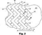
図2は、ワイヤ20および40がベースロール12(図2に示されていない)の周りに巻付けられた工具ロール10の表面の一部の拡大図である。ワイヤ20および40によって形成されたキャビティ30も、図2に示されている。図3は、ベースロール12、ワイヤ20および40、ならびにエンドキャップ50を示す、工具ロール10の一部の断面図である。図4は、工具ロール10のキャビティの形成を示す、ワイヤ20および40の斜視図である。
FIG. 2 is an enlarged view of a portion of the surface of
ベースロール12の周りに巻付けられたワイヤ20および40は、クランプ、溶接、接着剤などを含むが、これらに限定されない、任意の適切な機構によって所定位置に保持してもよい。そのような技術は、たとえば、カーディングロールの製造において知られている。たとえば、米国特許第4,272,865号明細書(シュモルケ(Schmolke))を参照のこと。いくつかの場合、エンドキャップ50および60も、ワイヤ20および40を円筒形ベースロール12上の所定位置に保持するために使用される機構の一部として役立つことができる。さらに、ワイヤが巻かれた表面に形成された溝を含むベースロール12を提供することが好ましく、溝は、ベースロール12上に巻かれたワイヤの位置を維持するのを助ける。
図1を参照すると、第1のエンドキャップ50は、好ましくは、円筒形ベースロール12の円周に延在し、ワイヤを修正螺旋コイルに巻くか巻付けることができるワイヤ巻き面52を設ける。ワイヤ巻き面52は、円筒形ベースロール12の第2端部に面し、好ましくは、ワイヤを形成できる波形面を提供する。所望の波形プロファイルまたは波形形状を、ワイヤ20および40の修正螺旋コイルに与えるために、ワイヤ巻き面52の代わりに、多くの他の構造または技術を用いることができる。たとえば、一連のピンまたは指を用いて、ワイヤ20および40を、ベースロール12上に巻く間、所望の波形プロファイルに支持することができる。
Referring to FIG. 1, the
本明細書で用いられる際の「波形」という用語は、ワイヤ20(およびワイヤ20とともに巻かれた他のいかなるワイヤ)と、長手方向軸線14に直角な、円筒形ベースロール12を通って延在する基準面との間の変化する距離を指す(基準面15の端縁が図1に示されている)。基準面15とワイヤ20との間の距離は、ベースロール12の円周を1方向に移動するとき、少なくとも1回、順次、増加し、減少する(本発明の円筒形工具ロールと関連して言及される距離は、特に明記しない限り、円筒形ベースロール12の長手方向軸線14に平行に測定される)。その結果、d1で表された距離は、ベースロール12の円周を移動するとき、少なくとも1回、増加し、減少する。これは、この距離が、ベースロール12の円周を1方向に移動するとき、増加または減少するが、1方向に移動するとき、増加し、かつ減少しない、従来の螺旋パターンと対照的である。基準面15とワイヤ20との間の距離が、ワイヤ20上の一貫した位置(たとえば、ワイヤ20の側面21と側面23との間)に沿って測定されることが理解されるであろう。
As used herein, the term “corrugated” extends through the wire 20 (and any other wire wound with the wire 20) and the
図2は、ワイヤ20および40が巻かれた工具ロール10の表面の拡大部分を示す。ワイヤ20および40は、エンドキャップ50のワイヤ巻き面52に適合し、円筒形ベースロール12の周りに巻かれるときに、ワイヤ巻き面52のプロファイルが、ワイヤ20および40の各々によって複製される。巻付けられたワイヤ20および40の螺旋性質の結果として、それらは、ロール12の一方の端部から反対側の端部まで、ベースロール12の面を横切って進む。ワイヤ20および40によって形成された修正螺旋コイルは、ベースロール12の円周を進むときに波形になるが、依然として、一般に、ベースロール12の面を横切って螺旋状に進む。
FIG. 2 shows an enlarged portion of the surface of the
ワイヤ20は、その中に形成された複数の空隙を含み、ワイヤ40は、ワイヤ20のコイル間のスペーサとして作用する。結果は、ワイヤ20およびスペーサワイヤ40の交互の螺旋コイルが、工具ロール10の表面にわたって配置される。ワイヤ20の空隙およびスペーサワイヤ40は、工具ロール10の面にモールドキャビティ30を定めるようにともに作用する。モールドキャビティ30が、同じサイズであり、工具ロール10の周りに均一に隔置されることが、好ましいが、不可欠ではないであろう。あるいは、モールドキャビティ30のサイズおよび/または間隔の、あるレベルの不均一性をもたらすことが望ましいであろう。
The
本発明によって製造される工具ロールの1つの可能な利点は、モールドキャビティ30が、たとえば工具ロール10の長手方向軸線に対して、配向が変わってもよいことである。たとえば、モールドキャビティは、図2に見られるように、異なった方向に角度をつけられてもよい。他の工具ロールにおいて、モールドキャビティをすべて、同じ配向で設けてもよい。
One possible advantage of a tool roll made according to the present invention is that the
図3および図4を参照すると、ワイヤ20の内縁24およびスペーサワイヤ40の内縁44が、ベースロール12の周りに巻付けられ、一方、ワイヤ20および40の外縁22および42が、それぞれ、ベースロール12から外方に面して巻かれている。ワイヤ20およびスペーサワイヤ40の両方とも、好ましくは、ロール10を横切る螺旋コイルの均一な前進と適合する矩形断面を有するであろう。
Referring to FIGS. 3 and 4, the
ワイヤ20に設けられた空隙26は、ワイヤ20の全幅を通して形成され、図3および図4に見られるように、対向する側壁27および28ならびに底部29を含む。完成した工具ロール10のモールドキャビティ30間の領域が、ほぼ滑らかである、すなわち、ワイヤ20とワイヤ40との間の著しい不連続がないように、ワイヤ20のコイルの外縁22が、スペーサワイヤ40の外縁42と同一平面上にあることが好ましいであろう。
A void 26 provided in the
あるいは、ワイヤ20および40の外縁22および42は、それぞれ、ベースロール12の表面より上の異なった高さに配置してもよい。異なった高さのワイヤ20および40は、製造されている物品の表面に構造を与えることができる。その構造は、たとえば、モールドキャビティによって形成されたより高い突出部および/または物品自体を強化することができる細長い隆起部の形態であってもよい。
Alternatively, the
上記のようにベースロール12の周りに巻かれたときに所望のモールドキャビティ30になる、中に形成された空隙を含むワイヤ20は、略矩形断面を有するワイヤまたはストリップを使用して製造してもよい。空隙26は、好ましくは、各空隙が、ワイヤ20の長さに沿って整列した2つの側部27および28、ならびに底部29のみを含むように、ワイヤ20の厚さを通して設けられる。ワイヤ20は、空隙26を備えて製造してもよいし、ほぼ均一なプロファイルを備えたワイヤを最初に製造し、次に、1つまたは複数の任意の適切な技術によって処理して、その中に空隙26を形成してもよい。1つまたは複数の適切な技術としては、パンチング、スタンピング、従来の機械加工、レーザ加工、放電加工、ウォータージェット加工、エッチングなどが挙げられるが、これらに限定されないであろう。所望の形状をもたらすためのワイヤのパンチングは、たとえば、カーディングロール産業において知られている。たとえば、米国特許第4,537,096号明細書(ホリングスワース(Hollingsworth))を参照のこと。ワイヤ20は、任意の適切な材料から製造してもよいが、いくつかの好ましい材料としては、鋼が挙げられ、より好ましくは、中炭素鋼から低炭素鋼が挙げられる。
The
さらなる変更例において、ワイヤ20および/または40の側面、すなわち、ワイヤ20の表面21および23ならびにワイヤ40の表面41および43(図3を参照のこと)のうちの1以上に、何らかの表面テクスチャーを設け、選択された1つまたは複数の側面が滑らかでないようにすることが好ましいであろう。たとえば、1つまたは複数の側面は、概ね滑らかな面から、ローレットパターンでエンボス加工しても、研削しても、パンチングしても、または他の方法で破壊してもよい。いかなるそのような表面テクスチャリングも、ワイヤ20の側面21および23のほぼ全体を延在することが好ましいであろう。この表面テクスチャリングは、処理中にキャビティからの空気の除去を向上させることによって、キャビティ30の充填を向上させることができる。適切な表面テクスチャーの一例が、図4に示されており、両方のワイヤ20および40の側面が、ローレット切り線のパターンを含むように示されている。
In a further variation, some surface texture is applied to one or more of the sides of the
ここで図1Aを参照すると、また、本発明の工具ロールと関連して与えてもよい別の任意の特徴は、上にワイヤが巻かれるベースロール12の表面にも、表面ベースロール12が滑らかにならないように表面テクスチャーを与えてもよいことである。ベースロール12の表面テクスチャリングも、捕捉された空気が逃げることができる付加的な経路を設けることによって、キャビティ30の充填を助けることができる。表面テクスチャリングは、また、使用中の、ベースロール12に対する、巻かれたワイヤの回転シフトを低減することができる。適切な表面テクスチャーの一例は、図1Aの拡大図に示されているように、ベースロール12の表面に形成された、ほぼ平行なローレット切り線のパターンであってもよい。
Referring now to FIG. 1A, another optional feature that may be provided in connection with the tool roll of the present invention is that the
図1および図2に示された波形螺旋ワイヤコイルプロファイルは、ピッチおよび大きさの両方が均一に変化するプロファイルの形態であるが、ワイヤと、長手方向軸線14に直角な、円筒形ベースロール12を通って延在する基準面との間の変化する距離をもたらすいかなるプロファイルも用いてもよいことが理解されるべきである。いくつかの代替プロファイルの例が、図5および図6に示されているが、示された例は、本発明と関連して用いてもよい可能なプロファイルを網羅していない。
The corrugated helical wire coil profile shown in FIGS. 1 and 2 is in the form of a profile that varies uniformly in both pitch and size, but with a
図1を参照すると、第2のエンドキャップ60も、好ましくは、ベースロール12の対向する端部のワイヤ巻き面52の形状またはプロファイルと相補的なプロファイルまたは形状を備えたワイヤ巻き面62を設けてもよい。ワイヤ巻き面52と同様に、ワイヤ巻き面62は、ベースロール12の円周で変化する、基準面15からの距離d2に配置されるように特徴づけることができる。第2ワイヤ巻き面62が第1ワイヤ巻き面52に相補的である場合、2つのワイヤ巻き面52および62の間の距離dは、ベースロール12の円周で、一定であるか、変わらない。
Referring to FIG. 1, the
図1および図2に示された波形プロファイルは、ベースロール12の円周で、順次、増加し、減少する、基準面15とワイヤ20との間の距離d1をもたらすように特徴づけてもよい。そのようなパターンは、ベースロール12の円周を1方向に移動するとき、一連の交互の順次的ピークおよび谷として示してもよい。ワイヤによって形成された各コイルは、少なくとも1つのピークと、少なくとも1つの谷とを含む。
The waveform profile shown in FIGS. 1 and 2 may be characterized to provide a distance d 1 between the
図1および図2に示された波形螺旋コイルは、線セグメントで連結された順次的ピークおよび谷によって形成されるが、修正螺旋コイルおよび関連したワイヤ巻き面(設けられている場合)のプロファイルは、他の形状を含んでもよい。たとえば、図5は、基準面とベースロールの円周のワイヤ120との間の距離dが、順次、増加し、減少するパターンの別の例を示す。図5に示されたプロファイルは、正弦波形として特徴づけてもよく、示されたパターンは、大きさおよび頻度に対して均一であるが、必要であれば、大きさおよび頻度の一方または両方に対して不均一性をもたらしてもよいことが理解されるであろう。
The corrugated helical coil shown in FIGS. 1 and 2 is formed by sequential peaks and valleys connected by line segments, but the profile of the modified helical coil and associated wire winding surface (if provided) is Other shapes may also be included. For example, FIG. 5 shows another example of a pattern in which the distance d between the reference surface and the
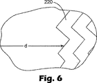
さらに、本発明と関連して使用される波形螺旋コイルが、基準面からの変化する距離をもたらす、波形に螺旋状に巻かれたワイヤを得るという目標を達成するいかなる所望の態様で、直線セグメントおよび/または湾曲を組合せてもよいことが理解されるべきである。図6は、図1、図2、および図5に示された湾曲したプロファイルからの方向により顕著な移行をもたらすように、ワイヤ220がクリンプされるか、他の方法で処理された1つの例示的なプロファイルを示す。
Further, the corrugated helical coil used in connection with the present invention can be a linear segment in any desired manner to achieve the goal of obtaining a spirally wound wire in a corrugated shape that provides a varying distance from the reference plane. It should be understood that and / or curvature may be combined. FIG. 6 illustrates one example where the
工具ロール10などの、本発明によって製造された工具ロールが使用される1つの好ましい用途は、高アスペクト形状構造化表面の製造である。図7を参照すると、工具ロール10を使用して形成された1つの例示的な物品70が、複数の突出部72が上に形成された構造化表面を含んで示されている。示された突出部は、物品70の表面74より上の高さh’と、表面74の平面に略平行な平面Iで測定された最小幅w’とを有する。表面74が、いくらかの湾曲を有する場合、平面Iは、好ましくは、突出部72の領域の表面74に接線方向に配向される。
One preferred application in which a tool roll made in accordance with the present invention is used, such as
突出部72は、高アスペクト比を有してもよく、本発明による工具ロールは、高アスペクト比形状を備えた構造化表面の製造に特に有利であろう。「高アスペクト比」とは、突出部高さと最小幅との比(h’:w’)が、たとえば、少なくとも約0.5:1以上、より好ましくは約1:1以上、さらに好ましくは、少なくとも約2:1以上であることを意味する。上で定義されたような高アスペクト比に加えて、またはその代わりに、物品の主面より上の突出部または構造の高さh’が、たとえば、約0.1ミリメートル以上、より好ましくは約0.2ミリメートル以上、さらに好ましくは約0.4ミリメートル以上であることが好ましいであろう。
The
物品70は、シートまたはフィルム形態で提供される場合、有利に、機械的ファスナ(たとえば、キノコタイプまたはフックタイプ機械的ファスナ)を製造するために使用してもよい。物品70が機械的ファスナとして使用される場合、突出部72は、通常、ステムと呼んでもよいが、その用語の使用は、本発明を用いて製造された物品の用途の範囲を限定するように意図されない。
If the article 70 is provided in sheet or film form, it may advantageously be used to manufacture mechanical fasteners (eg, mushroom type or hook type mechanical fasteners). Where the article 70 is used as a mechanical fastener, the
本発明の工具ロールおよび方法によって製造できる物品は、有利に、機械的ファスナとして使用されるが、物品にさまざまな他の用途があってもよいし、本発明による、工具ロール、および工具ロールを使用して構造化表面を備えた物品を製造する方法は、機械的ファスナの分野に限定されるべきではない。たとえば、本発明による物品の構造化表面上に形成された突出部は、たとえばフィルムの表面積を増加させることによって、接着剤または他のコーティング/材料を保持する点で利点をもたらすことができる。工具ロールによって形成された構造化表面は、また、流路、抵抗低減構造、研磨裏材などとして、装飾のために有用であろう。 Articles that can be produced by the tool roll and method of the present invention are advantageously used as mechanical fasteners, although the article may have a variety of other uses, and tool rolls and tool rolls according to the present invention The method of using to make an article with a structured surface should not be limited to the field of mechanical fasteners. For example, protrusions formed on the structured surface of an article according to the present invention can provide advantages in retaining adhesives or other coatings / materials, for example, by increasing the surface area of the film. The structured surface formed by the tool roll may also be useful for decoration, such as as a flow path, resistance reducing structure, abrasive backing, and the like.
図2〜4に示されたモールドキャビティ30は、それらの深さに沿って、工具ロール10の表面における開口部からモールドキャビティ底部29まで、ほぼ均一な断面積を有してもよい。図8は、いくつかの同様のモールドキャビティ330の拡大平面図であり、図9および図10は、それぞれ、線9−9および線10−10に沿ったモールドキャビティ330の断面図である。モールドキャビティ330は、それらの深さdに沿った略直線の接線方向の断面積を示す。接線方向のとは、断面が工具ロール310の接線に沿ってとられることを意味する。直線のとは、接線方向の断面におけるモールドキャビティ330の形状が、ほぼ平らな側部によって形成されることを意味する。
The mold cavities 30 shown in FIGS. 2-4 may have a substantially uniform cross-sectional area along their depth from the opening in the surface of the
モールドキャビティ330の側部327および328は、平行であってもよいし、側部327および328が、モールドキャビティ330の開口部において、モールドキャビティ330の底部におけるより離れているか、またはその逆であるように、ドラフト角度で形成してもよい。
The
本発明の工具ロールの1つの利点は、ワイヤ320の底部または内面324より上のモールドキャビティ330の底部329の高さhを精密に制御できることである。モールドキャビティ330の底部329は、典型的には、モールドキャビティの端部に相当する。
One advantage of the tool roll of the present invention is that the height h of the bottom 329 of the
好ましい円筒形ベースロール312は、厳しく制御された振れを有するように精密形成してもよい。その精密な振れは、ワイヤ320の厳しく制御された高さ寸法hと組合されて、工具ロール310の外面から測定された深さdがほぼ均一なモールドキャビティ330を提供することができる。高さ寸法hを制御できる公差は、一般に、比較的小さく、ベースロール312の振れは、厳しく制御することができ、それにより、完成した工具ロール310の全体的な厳しい公差制御をもたらすことができる。
The preferred
図11は、工具ロール410の外面への複数のモールドキャビティ430開口部を含む工具ロール410の別の例示的な実施形態を示す。工具ロール410の表面は、2つのワイヤ420および420’で巻くことができ、各ワイヤは、ともに巻かれると、モールドキャビティ430を形成する、中に形成された空隙を含む。工具ロール410と工具ロール10との1つの差(たとえば、図2を参照のこと)は、ほぼ均一な断面を有するスペーサワイヤ40の代わりに、工具ロール410は、両方とも中に形成された空隙を含む2つのワイヤを含むことである。工具ロール410の設計の1つの利点は、より高密度のモールドキャビティ430、すなわち、減少したモールドキャビティ430の間隔をもたらすことができることである。
FIG. 11 illustrates another exemplary embodiment of the
示された工具ロール410は、好ましくは、2つのワイヤ420および420’を使用して提供されるが、工具ロール410を、3以上のワイヤを使用して製造することができることが理解されるであろう。さらに別の代替例において、工具ロール410には、1つのワイヤを設けることができ、その場合、参照番号420および420’は、同じワイヤの交互の巻線またはコイルを示す。そのような実施形態は、ワイヤの隣接したコイルに形成されたモールドキャビティ430の整列を防止するために、ワイヤおよびベースロールの寸法のより厳しい制御が必要であろう。その制御を達成するのが困難なことがあるので、上記のように2以上の異なったワイヤを使用することが好ましいであろう。
The illustrated
本発明の工具ロールを製造するときに用いてもよい別の特徴は、巻いた後に工具ロール上にめっきまたは他のコーティングを加えることである。そのようなコーティングは、たとえば、米国特許第6,190,594号明細書(ゴーマン(Gorman)ら)に記載されている。コーティングに使用される1つまたは複数の材料は、所望の物理特性によって変わってもよい。望ましいいくつかの物理特性としては、増加した耐摩耗性、制御された剥離特徴、制御された表面粗さ、隣接したワイヤ巻線間の結合などが挙げられるが、これらに限定されない。いくつかの好ましい材料は、金属めっき、より詳細には、無電解ニッケルめっき、クロムなどであろう。 Another feature that may be used when manufacturing the tool roll of the present invention is to add a plating or other coating onto the tool roll after winding. Such coatings are described, for example, in US Pat. No. 6,190,594 (Gorman et al.). The material or materials used for the coating may vary depending on the desired physical properties. Some desirable physical properties include, but are not limited to, increased wear resistance, controlled delamination characteristics, controlled surface roughness, bonding between adjacent wire windings, and the like. Some preferred materials would be metal plating, more particularly electroless nickel plating, chromium, and the like.
完成した工具ロールの振れを向上させるために、1つまたは複数のワイヤを巻いた後、工具ロールの外面を機械加工することが望ましいであろう。機械加工は、上記のように任意のめっきまたは他のコーティングを加える前または後に行ってもよい。好ましいワイヤが、ワイヤの内縁より上の一定の高さで形成された空隙を含む場合(図2〜4と関連して説明されたように)、巻いた後、工具ロールの外面を機械加工すると、モールドキャビティの深さの均一性を向上させることができる。 In order to improve runout of the finished tool roll, it may be desirable to machine the outer surface of the tool roll after winding one or more wires. Machining may be performed before or after adding any plating or other coating as described above. When the preferred wire includes a void formed at a constant height above the inner edge of the wire (as described in connection with FIGS. 2-4), after winding, machining the outer surface of the tool roll The uniformity of the mold cavity depth can be improved.
たとえば、ワイヤパンチングおよび/または巻かれたロールの機械加工から残っているばりを、重炭酸ナトリウム(重曹)または同様の材料でロールをブラストすることによって除去することも望ましいであろう。完成した工具ロールは、また、モールドキャビティ内に、および/またはモールドキャビティ間の工具ロールの外面上に、所望の表面仕上げをもたらすように処理してもよい。たとえば、工具ロールの表面を、研削、化学エッチング、サンドブラスト、めっき、コーティングするか、他の方法で修正することが望ましいであろう。 For example, it may be desirable to remove flash remaining from wire punching and / or winding roll machining by blasting the roll with sodium bicarbonate (bicarbonate) or similar materials. The completed tool roll may also be treated to provide the desired surface finish within the mold cavities and / or on the outer surface of the tool roll between the mold cavities. For example, it may be desirable to grind, chemically etch, sand blast, plate, coat, or otherwise modify the surface of the tool roll.
米国特許第6,190,594号明細書(ゴーマン(Gorman)ら)は、また、上記のほぼ均一な空隙と異なる、本発明と関連して使用されるワイヤの空隙のさまざまな形状の例を示す。本発明による工具ロールの1つの利点は、また、異なった形状および/または配向を有するモールドキャビティを設けるために、空隙を、異なった形状および/または配向で形成することができることである。所望の突出部を備えた完成したフィルムを製造するためのこれらのモールドキャビティの一部の使用が、樹脂選択およびプロセス条件に依存することが理解されるであろう。 US Pat. No. 6,190,594 (Gorman et al.) Also describes examples of various shapes of wire voids used in connection with the present invention, which differ from the generally uniform voids described above. Show. One advantage of the tool roll according to the present invention is that the voids can also be formed with different shapes and / or orientations to provide mold cavities with different shapes and / or orientations. It will be appreciated that the use of some of these mold cavities to produce a finished film with the desired protrusions will depend on resin selection and process conditions.
別の変更例において、本発明による工具ロールは、米国特許第6,190,594号明細書(ゴーマン(Gorman)ら)に記載されているように、モールドキャビティが異なる領域を含んでもよい。一例において、1以上の領域にモールドキャビティを設けてもよく、一方、1以上の他の領域に、実質的にモールドキャビティがなくてもよい。別の例において、異なった領域のモールドキャビティが、異なってもよい。本発明による工具ロールは、あるいは、均一な形状でない、および/または工具ロールの円周に延在しない、モールドキャビティが異なる領域を含んでもよい。 In another variation, a tool roll according to the present invention may include regions with different mold cavities, as described in US Pat. No. 6,190,594 (Gorman et al.). In one example, mold cavities may be provided in one or more regions, while one or more other regions may be substantially free of mold cavities. In another example, the mold cavities in different regions may be different. A tool roll according to the present invention may alternatively include regions of different mold cavities that are not of a uniform shape and / or do not extend around the circumference of the tool roll.
上で示されたワイヤは、略矩形断面(ワイヤの長さに直角にとられた)を含むが、米国特許第6,190,594号明細書(ゴーマン(Gorman)ら)に記載されているように、他の断面を有するワイヤを使用することが好ましいであろう。 The wire shown above includes a generally rectangular cross-section (taken perpendicular to the length of the wire) but is described in US Pat. No. 6,190,594 (Gorman et al.). As such, it may be preferable to use wires having other cross sections.
図12は、空隙526を含むワイヤ520およびスペーサワイヤ540でベースロール512を巻いて、複数のモールドキャビティ530を含む工具ロール510を提供する1つのプロセスを示す。必要であれば、2を超えるワイヤをともに巻いてもよいことが理解されるであろう。螺旋コイルが上記の所望の波形プロファイルを呈するように、ワイヤ巻き面550に対して、巻かれたワイヤ520および540を定期的に圧縮するために、圧縮モールド560を提供することが望ましいであろう。圧縮モールド560は、方向563に作用し、いかなる所望の時間間隔で使用してもよい。たとえば、1巻きのほんの一部を巻付けた後、多数の巻きの後、または任意のランダムに選択された時間に、巻線に圧縮を加えることが望ましいであろう。さらに、巻線を所望の形状に維持するために、圧縮に加えて、任意の適切なことを用いることが望ましいであろう。たとえば、圧縮中に巻かれたワイヤを定期的にスポット溶接する、巻かれたワイヤに接着を付与することなどが好ましいであろう。
FIG. 12 illustrates one process for winding a
図13は、本発明による工具ロール610を使用して、高アスペクト形状フィルムを形成することができる1つのプロセスを示す。たとえば押出またはキャスト成形によって、成形可能な材料660を工具ロール610の表面に付与して、工具ロール610のモールドキャビティのレプリカである突出部672を含むフィルム670を作ることができる。好ましい実施形態において、工具ロール610から取外す時に、材料660の工具ロール610への接着は、材料660内の粘着より小さい。材料660の工具ロールへの接着が、工具ロール610を形成するのに使用される1つまたは複数のワイヤの引張強度を超えないことがさらに好ましいであろう。
FIG. 13 illustrates one process in which a
実質的にいかなる成形可能な材料も、本発明と関連して使用してもよい。成形可能な材料が熱可塑性樹脂であることが好ましいであろう。押出成形でき、有用なはずの熱可塑性樹脂としては、ポリ(エチレンテレフタレート)などのポリエステル、ナイロンなどのポリアミド、ポリ(スチレン−アクリロニトリル)、ポリ(アクリロニトリル−ブタジエン−スチレン)、ポリプロピレンなどのポリオレフィン、および可塑化ポリ塩化ビニルが挙げられる。1つの好ましい熱可塑性樹脂は、コネチカット州ダンバリーのユニオン・カーバイド(Union Carbide,Danbury,Connecticut)から7C05Nとして入手可能な、メルトフローインデックスが15の、ポリプロピレンとポリエチレンとの中衝撃コポリマーである。熱可塑性樹脂は、また、ポリエチレンとポリプロピレンとのブレンドを含むブレンド、ポリプロピレン−ポリエチレンコポリマーなどのコポリマーを含んでもよいし、多数の層として、または交互のゾーン内で共押出してもよい。可塑剤、充填剤、顔料、染料、酸化防止剤、離型剤などの添加剤も、成形可能な材料に組入れてもよい。 Virtually any moldable material may be used in connection with the present invention. It would be preferred that the moldable material be a thermoplastic resin. Thermoplastic resins that can be extruded and should be useful include polyesters such as poly (ethylene terephthalate), polyamides such as nylon, poly (styrene-acrylonitrile), poly (acrylonitrile-butadiene-styrene), polyolefins such as polypropylene, and Examples include plasticized polyvinyl chloride. One preferred thermoplastic resin is a medium impact copolymer of polypropylene and polyethylene with a melt flow index of 15, available as 7C05N from Union Carbide, Danbury, Connecticut, Connecticut. The thermoplastic resin may also comprise a blend, including a blend of polyethylene and polypropylene, a copolymer such as a polypropylene-polyethylene copolymer, and may be coextruded as multiple layers or in alternating zones. Additives such as plasticizers, fillers, pigments, dyes, antioxidants, mold release agents and the like may also be incorporated into the moldable material.
1つの好ましいプロセスにおいて、材料660を、工具ロール610およびバックアップロール680によって形成されたニップに押出すことによって供給する。バックアップロール680は、好ましくは、いくらかの圧力を与え、成形可能な材料660を、工具ロール610に設けられたモールドキャビティ630(図12を参照のこと)に押込むのを助ける。あるいは、バックアップロール680を、モールド材料を工具ロール610のモールドキャビティに押込むのを助けることができる、いかなる連続的に移動する表面に置換えてもよい。
In one preferred process,
工具ロール610の内部に真空を供給して、そうでなければモールドキャビティの完全な充填を妨げることがある空気の除去を助けてもよい。しかし、多くの場合、モールドキャビティ内の空気が、工具ロール610を製造するのに使用されるワイヤ間に逃げるので、真空を供給しないであろう。換言すれば、このプロセスを真空がない状態で行ってもよい。
A vacuum may be applied to the inside of the
工具ロール610およびバックアップロール680のいずれかまたは両方でいくらかの熱制御をもたらすことも、望ましいであろう。プロセス条件、成形可能な材料660の温度、成形可能な材料660の特性などによって、ロール610および680の一方または両方を加熱するか、ロール610および680の一方または両方を冷却するか、ロールの一方を加熱し、他方のロールを冷却することが望ましいであろう。
It may also be desirable to provide some thermal control at either or both of the
材料660を工具ロール610のモールドキャビティ内に押込み、十分に冷却して、1つまたは複数の所望の形状を維持できる突出部672を備えたフィルム670を形成した後、さらなる処理のために工具ロール610からストリップするか、フィルム670をロールに巻くことができる。たとえば、機械的ファスナストリップが望まれる場合、フィルム674を1つまたは複数のステーションに向けて、たとえば、米国特許第5,845,375号明細書(ミラー(Miller)ら)、同第5,077,870号明細書(メルビー(Melbye)ら)、国際公開第98/57565号パンフレット、国際公開第98/57564号パンフレット、国際公開第98/30381号パンフレット、および国際公開第98/14086号パンフレットに記載されているように、突出部を修正し、接着剤をコーティングし、他の処理を行ってもよい。
After the
所望の付加的な特性をフィルム670に与えるために、1以上の付加的な材料を、工具ロール610およびバックアップロール680によって形成されたニップに向けることが望ましいであろう。たとえば、織布または不織布ウェブをニップに向けてもよい。あるいは、たとえば、熱、接着剤、共押出などによって、フィルム670を1以上の付加的な層に積層してもよい。
It may be desirable to direct one or more additional materials to the nip formed by the
図14は、図13の線14−14に沿った、図13の装置の断面図である。工具ロール610は、フィルム670上の突出部672を形成するために成形可能な材料で充填されたモールドキャビティ630を含む。また図14に示されているのは、バックアップロール680上に形成された2つの隆起構造682である。示されたバックアップロール680上の隆起構造682の1つの利点は、各隆起構造が、フィルム670を分離できる弱い線またはゾーンを作ることができることである。しかし、隆起構造682は、任意であり、本発明と関連して設けなくてもよい。
14 is a cross-sectional view of the apparatus of FIG. 13 taken along line 14-14 of FIG.
バックアップロール680に組入れてもよい別の任意の特徴は、何らかの構造をロール680の表面に加えて、その表面積を増加させることである。バックアップロール680上の増加した表面積は、フィルム670上の表面積を増加させることができ、それにより、フィルム670の裏面674に付与された接着剤の接着を向上させることができる。有用な構造の一例は、1インチあたり約400線(1センチメートルあたり160線)のスケールの線角柱(linear prisms)のマイクロエンボス加工パターンであることができる。
Another optional feature that may be incorporated into the
図15は、中にモールドキャビティが形成されたワイヤで巻かれた工具ロールを使用する別のプロセスを示す。示されたプロセスは、一方の側から延在する突出部772と、反対側から延在する突出部772’とを有するフィルム770を形成する。両面フィルム770は、両方とも中に形成されたモールドキャビティを含む、対向する工具ロール710および710’によって形成される。突出部772および772’は、サイズ、形状、配向などの点で同じ特徴を有してもよいし、異なってもよい。
FIG. 15 illustrates another process using a tool roll wound with wire having a mold cavity formed therein. The process shown forms a
図16は、別の工具ロール810とバックアップロール880との界面の拡大断面図である。フィルム870が、2つのロール810および880の間に配置され、フィルム870の片面は、本質的に工具ロール810上の構造のネガティブイメージである、一連のほぼ連続的な隆起部が上に形成された状態で形成される。
FIG. 16 is an enlarged cross-sectional view of an interface between another
工具ロール810は、ベースロール812の周りに螺旋状に巻かれたワイヤ820および840によって形成される。ワイヤ840は、他方のワイヤ820より高いプロファイルを有し、ワイヤ840の巻線間に溝が形成された工具ロール810をもたらす。ワイヤ820および840は、略矩形プロファイルを有するように示されているが、あるいは、異なった形状を与えることができ、その場合、フィルム870も、図14に示されたのと異なった形状で形成されるであろう。さらに、2つの工具ロールを図15に示されたのと同様のプロセスで使用して、フィルムの両方の主面上に構造または突出部を備えたフィルムを形成することができることが理解されるであろう。
図16の工具ロール810の周りに巻付けられたワイヤ820および840によって形成された溝は、ロール810の円周で連続的であってもよいが、不連続的であってもよい。図17は、工具ロール810’の周りにいくらかの長さを延在するが、図16に関して上述されたように連続螺旋溝に形成されていないモールドキャビティ830’を含む工具ロール810’の平面図である。細長いモールドキャビティ830’は、上記のように中に形成された空隙を含むワイヤによって形成することができる。しかし、ロール810’に使用されるワイヤの空隙は、ワイヤの長さにわたって、より長い距離を延在する。
The grooves formed by the
これらの細長い空隙は、上の工具ロールに示されたように均一なサイズおよび間隔にしてもよいし、不均一なサイズおよび不均一な間隔にしてもよい。工具ロール810’は、ベースロールの周りに巻付けられると、不均一なサイズおよび間隔のモールドキャビティ830’を形成する、不均一なサイズおよび間隔の空隙を備えたワイヤを示す。 These elongated gaps may be of uniform size and spacing as shown in the tool roll above, or of non-uniform size and spacing. Tool roll 810 'represents a wire with a non-uniformly sized and spaced air gap that forms a non-uniformly sized and spaced mold cavity 830' when wound around the base roll.
工具ロール810’などのロールによって製造されたフィルムは、図18に示されたような細長い突出部872’を含む。ロール810’のモールドキャビティ830’が、不均一なサイズおよび間隔であるので、細長い突出部872’も、不均一なサイズおよび間隔である。 A film produced by a roll, such as tool roll 810 ', includes an elongated protrusion 872' as shown in FIG. Since the mold cavities 830 'of the roll 810' are non-uniform in size and spacing, the elongated protrusions 872 'are also non-uniform in size and spacing.
本明細書に引用された特許、特許出願、および刊行物をすべて、各々、個別に引用により援用するように、それらの全体を引用により本明細書に援用する。本発明のさまざまな修正および変更は、本発明の範囲から逸脱することなく当業者に明らかになるであろう。また、本発明は、本明細書に記載された例示的な実施形態に不当に限定されるべきではないことが理解されるべきである。 All patents, patent applications, and publications cited herein are hereby incorporated by reference in their entirety, as if each were individually incorporated by reference. Various modifications and alterations of this invention will become apparent to those skilled in the art without departing from the scope of this invention. It should also be understood that the present invention should not be unduly limited to the exemplary embodiments described herein.
Claims (5)
複数の第1空隙を有して前記ベースロールの周りに螺旋コイル状に巻かれた第1ワイヤとを備える工具ロールであって、前記第1ワイヤの前記複数の第1空隙が複数の第1キャビティを形成し、該複数の第1キャビティの各キャビティが工具ロールの外面に開口部を有し、
前記第1ワイヤと前記ベースロールの長手方向軸線に交差する基準面との間の距離が、前記ベースロールの円周に沿って1方向へ移動するに従い、少なくとも1回、順次に増加および減少する、
工具ロール。A cylindrical base roll having first and second ends spaced along a longitudinal axis;
A tool roll having a plurality of first gaps and a first wire wound in a spiral coil around the base roll, wherein the plurality of first gaps of the first wire are a plurality of first gaps. Forming a cavity, each cavity of the plurality of first cavities having an opening on the outer surface of the tool roll;
The distance between the first wire and the reference plane intersecting the longitudinal axis of the base roll increases and decreases sequentially at least once as it moves in one direction along the circumference of the base roll. ,
Tool roll.
Applications Claiming Priority (2)
| Application Number | Priority Date | Filing Date | Title |
|---|---|---|---|
| US10/024,919 US6767202B2 (en) | 2001-12-18 | 2001-12-18 | Tooling with helical coils for structured surface articles |
| PCT/US2002/033170 WO2003051611A1 (en) | 2001-12-18 | 2002-10-14 | Tooling with helical coils for structured surface articles |
Publications (3)
| Publication Number | Publication Date |
|---|---|
| JP2005511366A JP2005511366A (en) | 2005-04-28 |
| JP2005511366A5 JP2005511366A5 (en) | 2006-01-05 |
| JP4173814B2 true JP4173814B2 (en) | 2008-10-29 |
Family
ID=21823033
Family Applications (1)
| Application Number | Title | Priority Date | Filing Date |
|---|---|---|---|
| JP2003552521A Expired - Fee Related JP4173814B2 (en) | 2001-12-18 | 2002-10-14 | Tools with helical coils for structured surface articles |
Country Status (13)
| Country | Link |
|---|---|
| US (2) | US6767202B2 (en) |
| EP (1) | EP1458552B1 (en) |
| JP (1) | JP4173814B2 (en) |
| KR (1) | KR20040070217A (en) |
| CN (1) | CN100430210C (en) |
| AT (1) | ATE314190T1 (en) |
| AU (1) | AU2002337886A1 (en) |
| BR (1) | BR0214983A (en) |
| DE (1) | DE60208441T2 (en) |
| ES (1) | ES2254746T3 (en) |
| MX (1) | MXPA04005785A (en) |
| RU (1) | RU2311293C2 (en) |
| WO (1) | WO2003051611A1 (en) |
Families Citing this family (11)
| Publication number | Priority date | Publication date | Assignee | Title |
|---|---|---|---|---|
| US6767202B2 (en) * | 2001-12-18 | 2004-07-27 | 3M Innovative Properties Company | Tooling with helical coils for structured surface articles |
| US7186656B2 (en) * | 2004-05-21 | 2007-03-06 | Molecular Imprints, Inc. | Method of forming a recessed structure employing a reverse tone process |
| US6902389B2 (en) * | 2003-05-14 | 2005-06-07 | 3M Innovative Properties Company | Wire wound tooling |
| US20060246256A1 (en) * | 2005-04-28 | 2006-11-02 | 3M Innovative Properties Company | Elevated structured loop |
| US8034431B2 (en) * | 2006-01-25 | 2011-10-11 | 3M Innovative Properties Company | Intermittently bonded fibrous web laminate |
| SE529814C2 (en) * | 2006-04-11 | 2007-11-27 | Mattssonfoeretagen I Uddevalla | Wire-engraved engraving roll and method of making it |
| AU2007289078A1 (en) | 2006-08-30 | 2008-03-06 | David William Smith | Method of imparting a mono-axial or multiaxial stiffness to extruded materials and products resulting therefrom |
| US20080097517A1 (en) * | 2006-10-23 | 2008-04-24 | Webtec Converting, Llc. | External Nasal Dilator and Methods of Manufacture |
| US7645134B2 (en) * | 2006-12-19 | 2010-01-12 | 3M Innovative Properties Company | Ribbon wound roll |
| CN103778308B (en) * | 2014-03-03 | 2016-08-17 | 中国科学院金属研究所 | Blade is without the topological Compensation Fuzzy Optimization Design of surplus cold rolling processing mold |
| IL270791B2 (en) | 2017-05-25 | 2023-10-01 | Magic Leap Inc | Double-sided imprinting |
Family Cites Families (26)
| Publication number | Priority date | Publication date | Assignee | Title |
|---|---|---|---|---|
| US2570470A (en) * | 1950-05-16 | 1951-10-09 | United Shoe Machinery Corp | Bladed roll for working hides |
| US2793585A (en) * | 1953-06-26 | 1957-05-28 | American Optical Corp | Embossing dies and method of making same |
| US3007231A (en) * | 1960-01-18 | 1961-11-07 | Alloy Hardfacing Co | Method of producing metal rollers |
| US3192589A (en) * | 1960-07-18 | 1965-07-06 | Raymond C Pearson | Separable fastener |
| US3541216A (en) * | 1968-08-26 | 1970-11-17 | Chris Craft Ind Inc | Process for making an embossed product |
| US3828998A (en) * | 1973-02-20 | 1974-08-13 | F Gross | Scroll roll |
| DE2704157B2 (en) * | 1977-02-02 | 1980-06-26 | Kuesters, Eduard, 4150 Krefeld | Process for the production of a grooved roll |
| DE2704158C2 (en) * | 1977-02-02 | 1986-02-20 | Küsters, Eduard, 4150 Krefeld | Press roll |
| US4208767A (en) * | 1978-06-23 | 1980-06-24 | John D. Hollingsworth On Wheels, Inc. | Reclothable beater roll for open end spinning machines |
| US4537096A (en) * | 1978-09-06 | 1985-08-27 | Hollingsworth John D | Metallic card clothing and method and apparatus for making same |
| JPS6049408B2 (en) | 1979-05-25 | 1985-11-01 | ダイセル化学工業株式会社 | Waveform shaping method |
| EG14916A (en) * | 1981-03-30 | 1985-03-31 | Hollingsworth Gmbh | Carding element |
| US4775310A (en) * | 1984-04-16 | 1988-10-04 | Velcro Industries B.V. | Apparatus for making a separable fastener |
| US5077870A (en) * | 1990-09-21 | 1992-01-07 | Minnesota Mining And Manufacturing Company | Mushroom-type hook strip for a mechanical fastener |
| US5845375A (en) * | 1990-09-21 | 1998-12-08 | Minnesota Mining And Manufacturing Company | Mushroom-type hook strip for a mechanical fastener |
| US5887470A (en) * | 1993-04-06 | 1999-03-30 | Mirtsch; Frank | Method and apparatus for dent profiling |
| ES2102857T3 (en) * | 1993-06-11 | 1997-08-01 | Minnesota Mining & Mfg | REPRODUCTION TOOL MACHINED BY LASER. |
| IT1290781B1 (en) | 1996-05-28 | 1998-12-10 | Polifarma Spa | ACTIVE THERAPEUTIC AGENT FOR THE TREATMENT OF NEURONAL DEGENERATIVE DISEASES. |
| US5900350A (en) | 1996-06-06 | 1999-05-04 | Velcro Industries B.V. | Molding methods, molds and products |
| US6054091A (en) | 1996-10-03 | 2000-04-25 | Minnesota Mining And Manufacturing Co. | J hook-type hook strip for a mechanical fastener |
| US6039911A (en) | 1997-01-09 | 2000-03-21 | 3M Innovative Properties Company | Method for capping stem fasteners |
| US5868987A (en) | 1997-06-19 | 1999-02-09 | Minnesotamining And Manufacturing | Superimposed embossing of capped stem mechanical fastener structures |
| US6132660A (en) | 1997-06-19 | 2000-10-17 | 3M Innovative Properties Company | Method for forming headed stem mechanical fasteners |
| US5845374A (en) * | 1997-07-02 | 1998-12-08 | Briggs; Patrick A. | Golf strap gripper |
| US6190594B1 (en) * | 1999-03-01 | 2001-02-20 | 3M Innovative Properties Company | Tooling for articles with structured surfaces |
| US6767202B2 (en) * | 2001-12-18 | 2004-07-27 | 3M Innovative Properties Company | Tooling with helical coils for structured surface articles |
-
2001
- 2001-12-18 US US10/024,919 patent/US6767202B2/en not_active Expired - Fee Related
-
2002
- 2002-10-14 WO PCT/US2002/033170 patent/WO2003051611A1/en active IP Right Grant
- 2002-10-14 KR KR10-2004-7009064A patent/KR20040070217A/en not_active Application Discontinuation
- 2002-10-14 CN CNB028254384A patent/CN100430210C/en not_active Expired - Fee Related
- 2002-10-14 RU RU2004118407/12A patent/RU2311293C2/en not_active IP Right Cessation
- 2002-10-14 EP EP02773790A patent/EP1458552B1/en not_active Expired - Lifetime
- 2002-10-14 AU AU2002337886A patent/AU2002337886A1/en not_active Abandoned
- 2002-10-14 JP JP2003552521A patent/JP4173814B2/en not_active Expired - Fee Related
- 2002-10-14 DE DE60208441T patent/DE60208441T2/en not_active Expired - Lifetime
- 2002-10-14 AT AT02773790T patent/ATE314190T1/en not_active IP Right Cessation
- 2002-10-14 ES ES02773790T patent/ES2254746T3/en not_active Expired - Lifetime
- 2002-10-14 BR BR0214983-4A patent/BR0214983A/en active Search and Examination
- 2002-10-14 MX MXPA04005785A patent/MXPA04005785A/en active IP Right Grant
-
2004
- 2004-02-17 US US10/780,078 patent/US6969479B2/en not_active Expired - Fee Related
Also Published As
| Publication number | Publication date |
|---|---|
| EP1458552B1 (en) | 2005-12-28 |
| DE60208441D1 (en) | 2006-02-02 |
| BR0214983A (en) | 2004-12-14 |
| US20040159970A1 (en) | 2004-08-19 |
| WO2003051611A1 (en) | 2003-06-26 |
| MXPA04005785A (en) | 2004-09-13 |
| US6969479B2 (en) | 2005-11-29 |
| CN100430210C (en) | 2008-11-05 |
| CN1604839A (en) | 2005-04-06 |
| DE60208441T2 (en) | 2006-08-24 |
| US6767202B2 (en) | 2004-07-27 |
| KR20040070217A (en) | 2004-08-06 |
| ATE314190T1 (en) | 2006-01-15 |
| RU2004118407A (en) | 2005-12-10 |
| RU2311293C2 (en) | 2007-11-27 |
| AU2002337886A1 (en) | 2003-06-30 |
| ES2254746T3 (en) | 2006-06-16 |
| JP2005511366A (en) | 2005-04-28 |
| US20030111767A1 (en) | 2003-06-19 |
| EP1458552A1 (en) | 2004-09-22 |
Similar Documents
| Publication | Publication Date | Title |
|---|---|---|
| US7052639B2 (en) | Wire wound tooling | |
| US6190594B1 (en) | Tooling for articles with structured surfaces | |
| JP4173814B2 (en) | Tools with helical coils for structured surface articles | |
| US7645134B2 (en) | Ribbon wound roll | |
| JP2000512174A (en) | Molding of hook fasteners and other components | |
| JP5678249B2 (en) | Manufacturing method of belt mold | |
| AU2916002A (en) | Molding of fastening hooks and other devices |
Legal Events
| Date | Code | Title | Description |
|---|---|---|---|
| A521 | Request for written amendment filed |
Free format text: JAPANESE INTERMEDIATE CODE: A523 Effective date: 20051003 |
|
| A621 | Written request for application examination |
Free format text: JAPANESE INTERMEDIATE CODE: A621 Effective date: 20051003 |
|
| A977 | Report on retrieval |
Free format text: JAPANESE INTERMEDIATE CODE: A971007 Effective date: 20080708 |
|
| TRDD | Decision of grant or rejection written | ||
| A01 | Written decision to grant a patent or to grant a registration (utility model) |
Free format text: JAPANESE INTERMEDIATE CODE: A01 Effective date: 20080715 |
|
| A01 | Written decision to grant a patent or to grant a registration (utility model) |
Free format text: JAPANESE INTERMEDIATE CODE: A01 |
|
| A61 | First payment of annual fees (during grant procedure) |
Free format text: JAPANESE INTERMEDIATE CODE: A61 Effective date: 20080814 |
|
| R150 | Certificate of patent or registration of utility model |
Free format text: JAPANESE INTERMEDIATE CODE: R150 |
|
| FPAY | Renewal fee payment (event date is renewal date of database) |
Free format text: PAYMENT UNTIL: 20110822 Year of fee payment: 3 |
|
| FPAY | Renewal fee payment (event date is renewal date of database) |
Free format text: PAYMENT UNTIL: 20110822 Year of fee payment: 3 |
|
| FPAY | Renewal fee payment (event date is renewal date of database) |
Free format text: PAYMENT UNTIL: 20120822 Year of fee payment: 4 |
|
| LAPS | Cancellation because of no payment of annual fees |