JP4172890B2 - Half toroidal continuously variable transmission - Google Patents
Half toroidal continuously variable transmission Download PDFInfo
- Publication number
- JP4172890B2 JP4172890B2 JP34670799A JP34670799A JP4172890B2 JP 4172890 B2 JP4172890 B2 JP 4172890B2 JP 34670799 A JP34670799 A JP 34670799A JP 34670799 A JP34670799 A JP 34670799A JP 4172890 B2 JP4172890 B2 JP 4172890B2
- Authority
- JP
- Japan
- Prior art keywords
- input
- side disk
- disk
- output
- continuously variable
- Prior art date
- Legal status (The legal status is an assumption and is not a legal conclusion. Google has not performed a legal analysis and makes no representation as to the accuracy of the status listed.)
- Expired - Fee Related
Links
Images


Classifications
-
- F—MECHANICAL ENGINEERING; LIGHTING; HEATING; WEAPONS; BLASTING
- F16—ENGINEERING ELEMENTS AND UNITS; GENERAL MEASURES FOR PRODUCING AND MAINTAINING EFFECTIVE FUNCTIONING OF MACHINES OR INSTALLATIONS; THERMAL INSULATION IN GENERAL
- F16H—GEARING
- F16H57/00—General details of gearing
- F16H57/04—Features relating to lubrication or cooling or heating
- F16H57/042—Guidance of lubricant
- F16H57/043—Guidance of lubricant within rotary parts, e.g. axial channels or radial openings in shafts
-
- F—MECHANICAL ENGINEERING; LIGHTING; HEATING; WEAPONS; BLASTING
- F16—ENGINEERING ELEMENTS AND UNITS; GENERAL MEASURES FOR PRODUCING AND MAINTAINING EFFECTIVE FUNCTIONING OF MACHINES OR INSTALLATIONS; THERMAL INSULATION IN GENERAL
- F16H—GEARING
- F16H15/00—Gearings for conveying rotary motion with variable gear ratio, or for reversing rotary motion, by friction between rotary members
- F16H15/02—Gearings for conveying rotary motion with variable gear ratio, or for reversing rotary motion, by friction between rotary members without members having orbital motion
- F16H15/04—Gearings providing a continuous range of gear ratios
- F16H15/06—Gearings providing a continuous range of gear ratios in which a member A of uniform effective diameter mounted on a shaft may co-operate with different parts of a member B
- F16H15/32—Gearings providing a continuous range of gear ratios in which a member A of uniform effective diameter mounted on a shaft may co-operate with different parts of a member B in which the member B has a curved friction surface formed as a surface of a body of revolution generated by a curve which is neither a circular arc centered on its axis of revolution nor a straight line
- F16H15/36—Gearings providing a continuous range of gear ratios in which a member A of uniform effective diameter mounted on a shaft may co-operate with different parts of a member B in which the member B has a curved friction surface formed as a surface of a body of revolution generated by a curve which is neither a circular arc centered on its axis of revolution nor a straight line with concave friction surface, e.g. a hollow toroid surface
- F16H15/38—Gearings providing a continuous range of gear ratios in which a member A of uniform effective diameter mounted on a shaft may co-operate with different parts of a member B in which the member B has a curved friction surface formed as a surface of a body of revolution generated by a curve which is neither a circular arc centered on its axis of revolution nor a straight line with concave friction surface, e.g. a hollow toroid surface with two members B having hollow toroid surfaces opposite to each other, the member or members A being adjustably mounted between the surfaces
-
- F—MECHANICAL ENGINEERING; LIGHTING; HEATING; WEAPONS; BLASTING
- F16—ENGINEERING ELEMENTS AND UNITS; GENERAL MEASURES FOR PRODUCING AND MAINTAINING EFFECTIVE FUNCTIONING OF MACHINES OR INSTALLATIONS; THERMAL INSULATION IN GENERAL
- F16H—GEARING
- F16H57/00—General details of gearing
- F16H57/04—Features relating to lubrication or cooling or heating
- F16H57/048—Type of gearings to be lubricated, cooled or heated
- F16H57/0487—Friction gearings
- F16H57/049—Friction gearings of the toroid type
Description
【0001】
【産業上の利用分野】
この発明に係るハーフトロイダル型無段変速機は、自動車用自動変速装置を構成する変速ユニットとして利用する。
【0002】
【従来の技術】
自動車用変速機として、図6〜7に略示する様なハーフトロイダル型無段変速機を使用する事が研究されている。このハーフトロイダル型無段変速機は、例えば実開昭62−71465号公報に開示されている様に、入力軸1と同心に入力側ディスク2を支持し、この入力軸1と同心に配置された出力軸3の端部に出力側ディスク4を固定している。ハーフトロイダル型無段変速機を納めたケーシング5(後述する図9参照)の内側には、上記入力軸1並びに出力軸3に対し捻れの位置にある枢軸6、6を中心として揺動するトラニオン7、7を設けている。
【0003】
これら各トラニオン7、7は、両端部外側面に上記枢軸6、6を、各トラニオン7、7毎に互いに同心に、各トラニオン7、7毎に1対ずつ設けている。これら各枢軸6、6の中心軸は、上記各ディスク2、4の中心軸と交差する事はないが、これら各ディスク2、4の中心軸の方向に対しほぼ直角方向である、捩れの位置に存在する。又、上記各トラニオン7、7の中心部には変位軸8、8の基半部を支持し、上記枢軸6、6を中心として各トラニオン7、7を揺動させる事により、上記各変位軸8、8の傾斜角度の調節を自在としている。各トラニオン7、7に支持された変位軸8、8の先半部周囲には、それぞれパワーローラ9、9を回転自在に支持している。そして、各パワーローラ9、9を、上記入力側、出力側両ディスク2、4の内側面2a、4a同士の間に挟持している。
【0004】
上記入力側、出力側両ディスク2、4の互いに対向する内側面2a、4aは、それぞれ断面が、上記枢軸6を中心とする円弧若しくはこの様な円弧に近い曲線を回転させて得られる、断面円弧状の凹面をなしている。そして、球状凸面に形成された各パワーローラ9、9の周面9a、9aを、上記内側面2a、4aに当接させている。又、上記入力軸1と入力側ディスク2との間には、ローディングカム装置10を設け、このローディングカム装置10によって上記入力側ディスク2を、出力側ディスク4に向け弾性的に押圧しつつ、回転駆動自在としている。
【0005】
上述の様に構成されるハーフトロイダル型無段変速機の使用時、入力軸1の回転に伴って上記ローディングカム装置10が上記入力側ディスク2を、上記複数のパワーローラ9、9に押圧しつつ回転させる。そして、この入力側ディスク2の回転が、上記複数のパワーローラ9、9を介して出力側ディスク4に伝達され、この出力側ディスク4に固定の出力軸3が回転する。
【0006】
入力軸1と出力軸3との回転速度を変える場合で、先ず入力軸1と出力軸3との間で減速を行なう場合には、枢軸6、6を中心として前記各トラニオン7、7を揺動させ、各パワーローラ9、9の周面9a、9aが図6に示す様に、入力側ディスク2の内側面2aの中心寄り部分と出力側ディスク4の内側面4aの外周寄り部分とにそれぞれ当接する様に、各変位軸8、8を傾斜させる。
【0007】
反対に、増速を行なう場合には、上記各トラニオン7、7を揺動させ、各パワーローラ9、9の周面9a、9aが図7に示す様に、入力側ディスク2の内側面2aの外周寄り部分と出力側ディスク4の内側面4aの中心寄り部分とに、それぞれ当接する様に、上記各変位軸8、8を傾斜させる。これら各変位軸8、8の傾斜角度を図6と図7との中間にすれば、入力軸1と出力軸3との間で、中間の変速比を得られる。
【0008】
更に、図8〜9は、実願昭63−69293号(実開平1−173552号)のマイクロフィルムに記載された、より具体化されたハーフトロイダル型無段変速機を示している。入力側ディスク2と出力側ディスク4とは円管状の入力軸11の周囲に、それぞれ回転自在に支持している。又、この入力軸11の端部と上記入力側ディスク2との間に、ローディングカム装置10を設けている。一方、上記出力側ディスク4には、出力歯車12を結合し、これら出力側ディスク4と出力歯車12とが同期して回転する様にしている。
【0009】
1対のトラニオン7、7の両端部に互いに同心に設けた枢軸6、6は1対の支持板13、13に、揺動並びに軸方向(図8の表裏方向、図9の左右方向)に亙る変位自在に支持している。そして、上記各トラニオン7、7の中間部に、変位軸8、8の基半部を支持している。これら各変位軸8、8は、基半部と先半部とを互いに偏心させている。そして、このうちの基半部を上記各トラニオン7、7の中間部に回転自在に支持し、それぞれの先半部にパワーローラ9、9を回転自在に支持している。
【0010】
尚、上記1対の変位軸8、8は、上記入力軸11に対して180度反対側位置に設けている。又、これら各変位軸8、8の基半部と先半部とが偏心している方向は、上記入力側、出力側両ディスク2、4の回転方向に関して同方向(図9で左右逆方向)としている。又、偏心方向は、上記入力軸11の配設方向に対してほぼ直交する方向としている。従って上記各パワーローラ9、9は、上記入力軸11の配設方向に亙る若干の変位自在に支持される。
【0011】
又、上記各パワーローラ9、9の外側面と上記各トラニオン7、7の中間部内側面との間には、これら各パワーローラ9、9の外側面の側から順に、スラスト玉軸受14、14とスラストニードル軸受15、15とを設けている。このうちのスラスト玉軸受14、14は、上記各パワーローラ9、9に加わるスラスト方向の荷重を支承しつつ、これら各パワーローラ9、9の回転を許容する。又、上記各スラストニードル軸受15、15は、上記各パワーローラ9、9から上記各スラスト玉軸受14、14を構成する外輪16、16に加わるスラスト荷重を支承しつつ、上記各変位軸8、8の先半部及び上記外輪16、16が、これら各変位軸8、8の基半部を中心として揺動する事を許容する。又、上記各トラニオン7、7は、油圧式のアクチュエータ17、17により、前記各枢軸6、6の軸方向に亙る変位自在としている。
【0012】
更に、上記各トラニオン7、7の一端部(図9の右端部)を支持する支持板13をケーシング5の内面に支持する為の支持ポスト19の先端部には、給油ノズル20を設けている。この給油ノズル20の一部で上記入力側、出力側両ディスク2、4の内側面2a、4aに対向する部分(図9の表裏方向両端部分)には、それぞれノズル孔(図示せず)を設けている。ハーフトロイダル型無段変速機の運転時にこれら各ノズル孔からは、上記各ディスク2、4の内側面2a、4aに向けて潤滑油(トラクションオイル)を噴出し、これら各内側面2a、4aと上記各パワーローラ9、9の周面9a、9aとの当接部(トラクション部)を潤滑する。
【0013】
上述の様に構成されるハーフトロイダル型無段変速機の場合、入力軸11の回転はローディングカム装置10を介して入力側ディスク2に伝えられる。そして、この入力側ディスク2の回転が、1対のパワーローラ9、9を介して出力側ディスク4に伝えられ、更にこの出力側ディスク4の回転が、出力歯車12より取り出される。
【0014】
入力軸11と出力歯車12との間の回転速度比を変える場合には、上記各アクチュエータ17、17により上記1対のトラニオン7、7を、それぞれ逆方向に、例えば、図9の下側のパワーローラ9を同図の右側に、同図の上側のパワーローラ9を同図の左側に、それぞれ変位させる。この結果、これら各パワーローラ9、9の周面9a、9aと上記入力側ディスク2及び出力側ディスク4の内側面2a、4aとの当接部に作用する、接線方向の力の向きが変化する。そして、この力の向きの変化に伴って上記各トラニオン7、7が、支持板13、13に枢支された枢軸6、6を中心として、互いに逆方向に揺動する。この結果、前述の図6〜7に示した様に、上記各パワーローラ9、9の周面9a、9aと上記各内側面2a、4aとの当接位置が変化し、上記入力軸11と出力歯車12との間の回転速度比が変化する。
【0015】
ハーフトロイダル型無段変速機による動力伝達時には、構成各部の弾性変形に基づいて、上記各パワーローラ9、9が上記入力軸11の軸方向に変位する。そして、これら各パワーローラ9、9を支持した前記各変位軸8、8が、それぞれの基半部を中心として僅かに回動する。この回動の結果、上記各スラスト玉軸受14、14の外輪16、16の外側面と上記各トラニオン7、7の内側面とが相対変位する。これら外側面と内側面との間には、前記各スラストニードル軸受15、15が存在する為、この相対変位に要する力は小さい。
【0016】
上述の様に構成され作用するハーフトロイダル型無段変速機の場合には、上記入力軸11と出力歯車12との間での動力伝達を2個のパワーローラ9、9により行なっている。従って、各パワーローラ9、9の周面9a、9aと入力側、出力側両ディスク2、4の内側面2a、4aとの間で伝達される単位面積当たりの力が大きくなり、伝達可能な動力に限界を生じる。この様な事情に鑑みて、ハーフトロイダル型無段変速機により伝達可能な動力を大きくすべく、パワーローラ9、9の数を増やす事も、従来から考えられている。
【0017】
この様な目的でパワーローラ9、9の数を増やす為の構造の1例として、1組の入力側ディスク2と出力側ディスク4との間に3個のパワーローラ9、9を配置し、この3個のパワーローラ9、9によって動力の伝達を行なう事が、例えば特開平3−74667号公報に記載されている様に、従来から知られている。この公報に記載された構造の場合には、図10に示す様に、固定のフレーム21の円周方向等間隔の3個所位置に、それぞれが120度に折れ曲がった支持片22、22の中間部を枢支している。そして、隣り合う支持片22、22同士の間にそれぞれトラニオン7、7を、揺動並びに軸方向に亙る変位自在に支持している。
【0018】
上記各トラニオン7、7は、それぞれ油圧式のアクチュエータ17、17により、それぞれの両端部に互いに同心に設けた枢軸6の軸方向に亙る変位自在としている。上記各アクチュエータ17、17を構成する各油圧シリンダ23、23は、制御弁24を介して、油圧源であるポンプ25の吐出口に通じている。この制御弁24は、それぞれが軸方向(図10の左右方向)に亙って変位自在なスリーブ26とスプール27とを備える。
【0019】
それぞれが上記各トラニオン7、7に、変位軸8、8により枢支されたパワーローラ9、9の傾斜角度を変える場合には、制御モータ28により上記スリーブ26を軸方向(図10の左右方向)に変位させる。この結果、上記ポンプ25から吐出された圧油が、油圧配管を通じて上記各油圧シリンダ23、23に送り込まれる。そして、これら各油圧シリンダ23、23に嵌装された、上記各トラニオン7、7を枢軸の軸方向に亙り変位させる為の駆動ピストン29、29が、入力側ディスク2及び出力側ディスク4(図6〜8参照)の回転方向に関して同方向に変位する。又、上記各駆動ピストン29、29の変位に伴って上記各油圧シリンダ23、23から押し出された作動油は、やはり上記制御弁24を含む油圧配管(一部図示せず)を通じて、油溜30に戻される。
【0020】
一方、上記圧油の送り込みに伴う駆動ピストン29の変位は、カム31、リンク32を介して上記スプール27に伝達され、このスプール27を軸方向に変位させる。この結果、上記駆動ピストン29が所定量変位した状態で、上記制御弁24の流路が閉じられ、上記各油圧シリンダ23、23への圧油の給排が停止される。従って、上記各トラニオン7、7の軸方向に亙る変位量は、上記制御モータ28によるスリーブ26の変位量に応じただけのものとなる。
【0021】
【発明が解決しようとする課題】
図10に示した様に、互いに対向する1対の入力側ディスク2の内側面2aと出力側ディスク4の内側面4aとの間に3個のトラニオン7、7及びパワーローラ9、9を設ける、所謂スリーローラ型のハーフトロイダル型無段変速機の場合、トラクション部への潤滑油の供給を行ないにくい。即ち、前述の図8〜9に示した様に、互いに対向する1対の入力側ディスク2の内側面2aと出力側ディスク4の内側面4aとの間に2個のトラニオン7、7及びパワーローラ9、9を設ける、所謂ツーローラ型のハーフトロイダル型無段変速機の場合に設けていた様な給油ノズル20は、上記図10に示した構造には組み込めない。
従って、上記スリーローラ型のハーフトロイダル型無段変速機の実用化の為には、ツーローラ型の場合とは全く異なる給油構造を採用する必要がある。
本発明のハーフトロイダル型無段変速機は、この様な事情に鑑みて発明したものである。
【0022】
【課題を解決するための手段】
本発明のハーフトロイダル型無段変速機は、前述の図10に示した、従来のスリーローラ型のハーフトロイダル型無段変速機と同様に、ハウジングと、このハウジング内に回転自在に支持された入力軸と、この入力軸の周囲にこの入力軸と共に回転自在に支持された入力側ディスクと、その内側面をこの入力側ディスクの内側面に対向させた状態でこの入力側ディスクと同心に配置され、この入力側ディスクとは独立した回転を自在とされた出力側ディスクと、これら入力側ディスクと出力側ディスクとの間に設けられ、これら両ディスクの中心軸に対し捻れの位置にある枢軸を中心として揺動する、1対の入力側ディスク及び出力側ディスク毎に3個ずつのトラニオンと、これら各トラニオンの内側面から突出した、これら各トラニオン毎に1本ずつの変位軸と、これら各変位軸に回転自在に支持された状態で、上記入力側ディスクと出力側ディスクとの内側面同士の間に挟持された、上記各トラニオン毎に1個ずつのパワーローラとを備える。
【0023】
特に、本発明のハーフトロイダル型無段変速機に於いては、上記入力側ディスクの内側面と上記出力側ディスクの内側面との間に、上記ハウジング内に固定されたフレームの一部が、上記入力軸を中心とする円周方向に隣り合う上記各パワーローラ同士の間に位置する状態で配置されている。又、上記フレームは、上記各トラニオンを支持する支持環と、この支持環に外径側端部を支持固定されるステーとを備える。又、上記フレームの一部である、このステーの一部で上記円周方向に隣り合う上記各パワーローラ同士の間に位置する支柱部に、これら各パワーローラの周面と上記各ディスクの内側面との当接部を潤滑する為の潤滑油を、これら各ディスクの内側面のうちの小径側端部に向けて噴出する為のノズル孔が設けられている。そして、中空管状に形成した上記入力軸内に送り込んだ潤滑油を、上記ノズル孔に送り込み自在としている。
【0024】
【作用】
上述の様に構成する本発明のハーフトロイダル型無段変速機が入力側ディスクから出力側ディスクに、複数のパワーローラを介して動力の伝達を行なう作用は、前述した従来のハーフトロイダル型無段変速機の場合と同様である。
特に、本発明の場合には、入力軸の側からフレームを構成するステーを介して、上記各パワーローラの周面と上記各ディスクの内側面との当接部を潤滑する為の潤滑油を供給する為、給油ノズルの設置スペースの確保が難しい、スリーローラ型のハーフトロイダル型無段変速機でも、上記当接部への潤滑油供給を十分に行なえる。
【0025】
【発明の実施の形態】
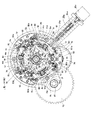
図1〜5は、本発明の実施の形態の1例を示している。尚、図示の例は、本発明のハーフトロイダル型無段変速機33を、乗用車用としては大型で大きなトルクを発生するエンジンを組み込んだ四輪駆動車用の自動変速装置の変速ユニットとして利用する場合に就いて示している。この為、上記ハーフトロイダル型無段変速機33を構成する第一入力側ディスク34と第一出力側ディスク35との間に3個の第一パワーローラ36、36を、第二入力側ディスク37と第二出力側ディスク38との間に3個の第二パワーローラ39を、それぞれ設けて、合計6個のパワーローラ36、39により、動力の伝達を行なう様に構成している。
【0026】
上記自動変速装置を構成する為、動力の伝達方向に関して最も前段部には、発進クラッチであるトルクコンバータ40を設け、このトルクコンバータ40の出力部に、上記ハーフトロイダル型無段変速機33を構成する入力軸11の前半部11aを組み込んでいる。図示しない走行用エンジンの回転に伴ってこの前半部11aは、上記トルクコンバータ40により回転駆動される。そして、この前半部11aの後端部に上記入力軸11の後半部11bを、1対のラジアルニードル軸受41a、41bを介して、互いに同心に且つ相対回転自在に支持している。
【0027】
そして、上記前半部11aと後半部11bとの間に、前進と後退とを切り換える為の前後進切り換えユニット42を、動力の伝達方向に関して直列に設けている。遊星歯車機構である、この前後進切り換えユニット42は、それぞれが湿式多板クラッチである前進用クラッチ43と後退用クラッチ44とを選択して切り換える事により、前進状態と後退状態とを切り換える。尚、遊星歯車機構を使用した前後進切り換えユニット42の構造及び作用は、従来から周知であり、又、本発明の要旨とも関係しない為、詳しい説明は省略する。
【0028】
動力の伝達方向に関して、上述の様な前後進切り換えユニット42の後側には、本発明の対象であるハーフトロイダル型無段変速機33を設けている。そして、このハーフトロイダル型無段変速機33の入力部、即ち、上記前後進切り換えユニット42の出力部につながる部分と、出力部、即ち、前輪用駆動軸45及び後輪用駆動軸46につながる部分との間の変速比を連続的に変化させる様にしている。このハーフトロイダル型無段変速機33は、上記後半部11bの周囲に設けている。即ち、この後半部11bの前後両端部近傍に第一、第二両入力側ディスク34、37を、それぞれが断面円弧状の凹面である内側面2a、2a同士を対向させた状態で、互いに同心に且つ互いに同期した回転自在に支持している。この為に図示の例では、前側(図1の左側)に設けた第一入力側ディスク34を、前記前後進切り換えユニット42を構成するキャリア47の基端部にスプライン係合させると共に、前側への移動を阻止している。これに対して、後側(図1の右側)に設けた第二入力側ディスク37は、上記後半部11bの後端部に、ボールスプライン48を介して支持している。そして、油圧式のローディング装置49により、上記第二入力側ディスク37を上記第一入力側ディスク34に向け、押圧自在としている。
【0029】
又、前記後半部11bの中間部周囲には支持筒50を、この後半部11bと同心に設けている。この支持筒50は、ステー51、51の内径側端部により、その両端部を支持固定している。尚、これら各ステー51、51は、後述する支持環52、52にそれぞれの外径側端部を支持固定して、やはり後述する第一、第二各揺動フレーム53、54を揺動自在に支持する為の第一、第二各支持フレーム55、56を構成する。又、上記後半部11bの中間部外周面と上記支持筒50の両端部内周面との間には、それぞれラジアルニードル軸受57、57を設けて、上記後半部11bを上記支持筒50の内側に、回転及び軸方向に亙る変位自在に支持している。
【0030】
これに対して、上記支持筒50の周囲には、前記第一、第二両出力側ディスク35、38を、それぞれラジアルニードル軸受58、58により、回転及び軸方向に亙る変位自在に支持している。又、上記第一、第二両出力側ディスク35、38の互いに対向する端面同士の間には、スラストニードル軸受59を設けて、これら両出力側ディスク35、38同士の間に加わるスラスト荷重を支承しつつ、これら両出力側ディスク35、38同士の相対回転を自在としている。
【0031】
上記支持筒50の両端部を支持固定する為、上記各ステー51、51の内径側端部(中心部)に設けた、短円筒状の支持環部60、60の内周面には凹溝61、61を、それぞれ全周に亙って形成している。又、上記各ステー51、51の一部で、円周方向に隣り合う第一パワーローラ36、36同士(第二パワーローラ39同士)の間に位置する支柱部62、62の内径寄り端部には、それぞれ図5に示す様な給油通路64を設けている。これら各給油通路64の外径側端部開口は、プラグ63により塞いでいる。又、上記各支柱部62、62の側面で、前記各ディスク34、35、37、38の内側面2a、4aに対向する部分には、それぞれの上流端を上記各給油通路64に通じさせたノズル孔65、65の下流端を開口させている。
【0032】
又、上記支持筒50の両端部内周面には円輪状の堰板66、66を固定すると共に、これら各堰板66、66の内周縁を前記後半部11bの中間部外周面に近接対向させて、この後半部11bの外周面と上記支持筒50の内周面との間の円筒状空間67の両端開口部をほぼ塞いでいる。又、上記後半部11bは中空円管状に形成してその中心部に給油通路68を設け、この給油通路68の一端を、図示しない給油ポンプの吐出口等の給油手段部分に通じさせている。そして、この後半部11bの中間部複数個所に形成した給油孔69、69により、上記給油通路68と上記円筒状空間67とを連通させている。更に、上記支持筒50の両端部で上記各凹溝61、61に整合する位置には、それぞれ別の給油孔70、70を形成している。
【0033】
又、前記第一出力側ディスク35の外側面側には前輪用出力歯車71を固定し、この前輪用出力歯車71と前記前輪用駆動軸45とを、前輪用従動歯車73を介して結合し、上記第一出力側ディスク35により上記前輪用駆動軸45を回転駆動自在としている。又、この前輪用駆動軸45の回転を、前輪用デファレンシャルギヤ74を介して、図示しない前輪に伝達自在としている。一方、上記第二出力側ディスク38の外側面側には後輪用出力歯車75を固定し、この後輪用出力歯車75と前記後輪用駆動軸46とを、後輪用出力歯車76を介して結合し、上記第二出力側ディスク38により上記後輪用駆動軸46を回転駆動自在としている。又、この後輪用駆動軸46の回転を、図示しない後輪用デファレンシャルギヤを介して、やはり図示しない後輪に伝達自在としている。
【0034】
又、前記第一入力側ディスク34の内側面2aと上記第一出力側ディスク35の内側面4aとの間には前記3個の第一パワーローラ36、36を、前記第二入力側ディスク37の内側面2aと上記第二出力側ディスク38の内側面4aとの間には前記3個の第二パワーローラ39を、それぞれ挟持している。これら第一、第二各パワーローラ36、39は、それぞれ第一、第二各トラニオン77、78の内側面に回転自在に支持している。これら第一、第二各トラニオン77、78は、それぞれの両端部に互いに同心に設けた、上記各ディスク34、37、35、38の中心軸と交差する事はないが、これら各ディスク34、37、35、38の中心軸の方向に対して直角若しくは直角に近い方向となる捻れの位置に存在する第一、第二各枢軸79(第二枢軸は図示せず)を中心に揺動する。又、上記第一、第二各トラニオン77、78は、それぞれ第一、第二各揺動フレーム53、54の両端部に、ラジアルニードル軸受80、80により、揺動変位自在に支持している。
【0035】
そして、上記第一、第二各揺動フレーム53、54の中間部を前記第一、第二各支持フレーム55、56を構成する前記各支持環52、52同士の間に、各ディスク34、37、35、38の中心軸に対し平行な支持軸81、81を中心とする揺動変位自在に支持している。尚、これら各支持軸81、81及び上記各支持環52、52と上記第一、第二各揺動フレーム53、54との間には、それぞれニードル軸受等のラジアル軸受及びスラスト軸受を設けて、上記第一、第二各揺動フレーム53、54の揺動が円滑に行なわれる様にしている。上記第一、第二各支持フレーム55、56は、互いに平行に配置されたそれぞれ1対ずつの支持環52、52を、前記ステー51を構成する3本の支柱部62、62の外径側端部を介して互いに結合して成る。上記各支持軸81、81は、上記各支持環52、52の円周方向に関して、上記各支柱部62、62の中間位置で、上記第一、第二各支持フレーム55、56を1対ずつの支持環52、52同士の間に掛け渡している。従って、上記第一、第二各揺動フレーム53、54は、円周方向に隣り合う支柱部62、62同士の間に、揺動自在に支持されている。
【0036】
更に、上記第一、第二各揺動フレーム53、54を、これら各揺動フレーム53、54の両端部と上記各支持環52、52との間に設けた油圧シリンダ82a、82bにより、揺動変位自在としている。これら各油圧シリンダ82a、82bは、それぞれ上記各支持環52、52の一部で上記各揺動フレーム53、54の両端部に整合する位置に設けている。一方、上記第一、第二各揺動フレーム53、54の両端部で、上記各油圧シリンダ82a、82bに整合する部分にはロッド83a、83bを、上記各支持軸81、81と平行に、上記第一、第二各揺動フレーム53、54の両端部を貫通する状態で支持固定している。そして、上記各油圧シリンダ82a、82bに嵌装したピストン84a、84bと、上記各ロッド83a、83bを係合させている。
【0037】
尚、これら各ピストン84a、84bの直線運動と上記第一、第二各揺動フレーム53、54の両端部の円弧運動との相違に拘らず、上記各ピストン84a、84bによりこれら第一、第二各揺動フレーム53、54を揺動変位自在とする為、上記各ロッド83a、83bはこれら第一、第二各揺動フレーム53、54の両端部に、上記各ピストン84a、84bの移動方向に対し直角方向に亙る若干の変位自在に支持している。図示の例では、上記各ロッド83a、83bの両端部を、それぞれ支持環52、52に形成した、これら各支持環52、52の直径方向に長い長孔85、85に遊合させているが、これら各長孔85、85の幅を上記各ロッド83a、83bの外径よりも大きくして、上記直角方向に亙る変位を自在としている。
【0038】
変速時には、上記各揺動フレーム53、54毎に2対ずつ(各揺動フレーム毎に4個ずつ、ハーフトロイダル型無段変速機33全体として合計24個)設けた油圧シリンダ82a、82bのうちの、上記各揺動フレーム53、54の長さ方向一端側に設けた一方の油圧シリンダ82a(82b)を伸長させると共に他方の油圧シリンダ82b(82a)を収縮させて、上記各揺動フレーム53、54を所定方向に所定量だけ揺動変位させる。
【0039】
又、上記各油圧シリンダ82a、82bへの圧油の給排を制御する為の制御弁24aは、前記各支持環52、52に支持している。上記各油圧シリンダ82a、82bへの圧油の給排により上記各揺動フレーム53、54が揺動変位すると、これら各揺動フレーム53、54に支持したトラニオン77、78の外側面に設けたカム面86が、上記制御弁24aに付属のプランジャ87を介してこの制御弁24aのスプール27aを変位させ、上記制御弁24aの切り換えを行なう。このスプール27aと共にこの制御弁24aを構成するスリーブ26aは、変速時には所望の変速比を実現できる様に、制御モータ28aにより、所定位置に変位させておく。この様な制御弁24a及び制御モータ28aは、前記第一入力側ディスク34及び第一出力側ディスク35を含んで構成する第一キャビティ88側に1個、前記第二入力側ディスク37及び第二出力側ディスク38を含んで構成する第二キャビティ89側に1個、ハーフトロイダル型無段変速機33全体で2個設けている。そして、第一キャビティ88側の制御モータ28aによりこの第一キャビティ88側の制御弁24aを、第二キャビティ89側の制御モータ28aによりこの第二キャビティ89側の制御弁24aを、マイクロコンピュータを内蔵した図示しない制御器からの指令信号に基づき、互いに同期して(直進状態の場合)、或は互いに独立して(旋回状態の場合)制御する。
【0040】
この様に構成する為、変速時には、上記各油圧シリンダ82a、82bへの圧油の給排に基づき、上記第一、第二各揺動フレーム53、54が、前記各支持軸81、81を中心に、所定方向に所定量だけ揺動変位する。この結果、これら各揺動フレーム53、54に支持された上記第一、第二各トラニオン77、78が、ほぼ上記第一、第二枢軸79の軸方向に変位(実際には、上記各支持軸81、81を中心とする円弧運動)する。そして、前述の図8〜9に示した従来構造の場合と同様に、前記各パワーローラ36、39の周面9a、9aと上記各ディスク34、37、35、38の内側面2a、4aとの当接部に作用する、接線方向の力の向きが変化する。そして、この力の向きの変化に伴って上記第一、第二各トラニオン77、78が、上記第一、第二各揺動フレーム53、54に枢支された第一、第二各枢軸79を中心として、互いに逆方向に揺動し、前述の図6〜7に示した様に、上記第一、第二各パワーローラ36、39の周面9a、9aと上記各内側面2a、4aとの当接位置が変化して、第一、第二各入力側ディスク34、37と第一、第二各出力側ディスク35、38との間の回転速度比が変化する。
【0041】
尚、図示の例では、上記第一、第二各トラニオン77、78に対して上記第一、第二各パワーローラ36、39を支持する為の変位軸8a、8aを、基半部と先半部とを特に偏心させない、直線状のものを使用している。代わりに、上記各変位軸8a、8aの先端部を、スラスト玉軸受14a、14aを構成する外輪16a、16aの中心から外れた位置に内嵌させている。又、上記第一、第二各パワーローラ36、39は、貫通孔を持たない丸鉢状に形成し、上記スラスト玉軸受14a、14aに接触角を持たせる(アンギュラコンタクトとする)事で、上記スラスト玉軸受14a、14aに加わるスラスト荷重の他、ラジアル荷重も支承自在としている。この様な構造によっても、上記第一、第二各パワーローラ36、39を所定位置に回転自在に、且つ上記各ディスク34、37、35、38の軸方向に亙る若干の変位自在に支持できる。
【0042】
上述の様に構成する本例の四輪駆動車用ハーフトロイダル型無段変速装置の運転時には、前記入力軸11の後半部11bと共に互いに同期して回転する第一、第二両入力側ディスク34、37のうち、第一入力側ディスク34から上記各第一パワーローラ36、36を介して前記第一出力側ディスク35に伝わった動力により、前記前輪用駆動軸45を回転駆動する。又、第二入力側ディスク37から上記各第二パワーローラ39を介して前記第二出力側ディスク38に伝わった動力により、後輪用駆動軸46を回転駆動する。
【0043】
上記第一、第二両入力側ディスク34、37と上記第一、第二両出力側ディスク35、38との間の伝達効率を確保すべく、これら各ディスク34、37、35、38の内側面2a、4aと上記第一、第二各パワーローラ36、39の周面9a、9aとの当接部の面圧は、前記油圧式のローディング装置49を構成する油圧室に導入する油圧を変える事により、容易に調整できる。フルタイム4WD車用の変速装置の場合、走行条件により、前輪に分配するトルクと後輪に分配するトルクとが異なる場合が生じるが、本例の場合には、上記面圧の調整を上記油圧式のローディング装置49により行なう為、条件に応じて最適の面圧の付与を行なえる。
【0044】
自動車が直進状態で、前輪の回転速度と後輪の回転速度とを一致させるべく、上記前輪用駆動軸45の回転速度と上記後輪用駆動軸46の回転速度とを一致させる際には、前記各油圧シリンダ82a、82bへの圧油の給排に基づく、前記支持軸81、81を中心とする前記第一、第二各揺動フレーム53、54の揺動角度、並びにこれら各揺動フレーム53、54に支持した、前記第一、第二各枢軸79を中心とする第一、第二各トラニオン77、78の傾斜角度を一致させる。そして、上記第一入力側ディスク34と上記第一出力側ディスク35との間の変速比と、上記第二入力側ディスク37と上記第二出力側ディスク38との間の変速比とを一致させる。尚、ハーフトロイダル型無段変速機33の出力部と前輪及び後輪との間の減速比は、デファレンシャルギヤを含む全体で、互いに一致させる。
【0045】
これに対して、自動車が旋回状態で、上記前輪の回転速度に比べて上記後輪の回転速度を遅くすべく、上記前輪用駆動軸45の回転速度に比べて上記後輪用駆動軸46の回転速度を遅くする際には、上記各第一トラニオン77、77の傾斜角度と、上記各第二トラニオン78の傾斜角度を異ならせる。具体的には、上記第一入力側ディスク34と上記第一出力側ディスク35との間の減速比に比べて、上記第二入力側ディスク37と上記第二出力側ディスク38との間の減速比を大きくする。この結果、センターデフを設けなくても、前輪及び後輪と路面との間に過大な滑りを発生する事なく、自動車の運行を安定して行なわせる事ができる。
【0046】
何れにしても、ハーフトロイダル型無段変速機の運転時に、第一、第二各パワーローラ36、39から第一、第二各トラニオン77、78を介して第一、第二揺動フレーム53、54には、前記各ディスク34、37、35、38の直径方向外方に向く、大きな荷重が加わる。これらの荷重は、前記各支持軸81、81から、前記第一、第二各支持フレーム55、56を構成する支持環52、52に伝わり、これら各支持環52、52内で相殺される。従って、これら各支持環52、52の剛性を確保さえすれば、ハーフトロイダル型無段変速機を収納するケーシングの剛性及び強度を、徒に高くする必要はなく、ハーフトロイダル型無段変速機の小型・軽量化を図れる。
【0047】
又、ハーフトロイダル型無段変速機の運転時には、前記入力軸11の後半部11b内の給油通路68に潤滑油を送り込む。この潤滑油は、前記給油孔69、69を通じて、前記支持筒50の内径側に存在する円筒状空間67に吐出し、更にこの円筒状空間67から、前記給油孔70、70、前記各凹溝61、61、前記各給油通路64に送り込まれる。更に、これら各給油通路64に送り込まれた潤滑油は、前記各ノズル孔65、65の下流端開口から、前記各ディスク34、35、37、38の内側面2a、4aに噴出する。そして、これら各内側面2a、4aに付着した潤滑油は、これら各内側面2a、4aと前記各パワーローラ36、39の周面9a、9aとの当接部に送り込まれ、これら各面2a、4a、9a同士の当接部を潤滑する。
【0048】
尚、図示の例では、本発明のハーフトロイダル型無段変速機を、大型で大きなトルクを発生するエンジンを組み込んだ四輪駆動車用の自動変速装置用の変速ユニットとして組み込んだ場合に就いて説明した。但し、本発明の特徴は、スリーローラ型のハーフトロイダル型無段変速機の給油構造にあり、図示の様な四輪駆動車用に限らず、一般的な二輪駆動車の為の自動変速装置用の変速ユニットとしても使用できる。この場合には、1対の出力側ディスクを互いに同期した回転を自在に結合し、これら両出力側ディスクから1本の出力軸に出力を取り出す。更には、あまり大きなトルクを発生しない、小型の自動車の為の自動変速装置用の変速ユニットとして使用する場合には、入力側ディスクと出力側ディスクとを1個ずつ設けた、所謂シングルキャビティ型のハーフトロイダル型無段変速機として構成する事もできる。又、変速時に各トラニオンを変位させる為の構造も、図の様な揺動フレームを使用するものに限らず、前述の図10に示す様な、平行移動式のものでも良い。更には、トラクション部の面圧を確保する為のローディング装置に関しても、例えば二輪駆動車用の自動変速機を構成する場合には、図示の様な油圧式のものである必要はなく、前述した従来構造の様な、機械式に押圧力を発生させる、ローディングカム装置でも良い。
【0049】
【発明の効果】
本発明は、以上に述べた通り構成され作用するので、1対の入力側ディスクと出力側ディスクとの間にパワーローラを3個設けた、スリーローラ型のハーフトロイダル型無段変速機の潤滑を効果的に行なえる構造を実現して、この型のハーフトロイダル型無段変速機の実現に寄与できる。
【図面の簡単な説明】
【図1】 本発明の実施の形態の1例を示す要部断面図。
【図2】 図1のA−A断面図。
【図3】 同B−B断面図。
【図4】 図3とほぼ同じ部分を、第一トラニオンの両端部に設けた第一枢軸の中心軸を含む平面で切断した状態で示す断面図。
【図5】 図1の中央部拡大断面図。
【図6】 従来から知られたハーフトロイダル型無段変速機の基本的構成を、最大減速時の状態で示す側面図。
【図7】 同じく最大増速時の状態で示す側面図。
【図8】 従来の具体的構造の1例を示す断面図。
【図9】 図8のC−C断面図。
【図10】 従来から知られた、伝達可能な動力を大きくする構造の1例を、一部を切断した状態で示す要部正面図。
【符号の説明】
1 入力軸
2 入力側ディスク
2a 内側面
3 出力軸
4 出力側ディスク
4a 内側面
5 ケーシング
6 枢軸
7 トラニオン
8、8a 変位軸
9 パワーローラ
9a 周面
10 ローディングカム装置
11 入力軸
11a 前半部
11b 後半部
12 出力歯車
13 支持板
14、14a スラスト玉軸受
15 スラストニードル軸受
16、16a 外輪
17 アクチュエータ
19 支持ポスト
20 給油ノズル
21 フレーム
22 支持片
23 油圧シリンダ
24、24a 制御弁
25 ポンプ
26、26a スリーブ
27、27a スプール
28、28a 制御モータ
29 駆動ピストン
30 油溜
31 カム
32 リンク
33 ハーフトロイダル型無段変速機
34 第一入力側ディスク
35 第一出力側ディスク
36 第一パワーローラ
37 第二入力側ディスク
38 第二出力側ディスク
39 第二パワーローラ
40 トルクコンバータ
41a、41b ラジアルニードル軸受
42 前後進切り換えユニット
43 前進用クラッチ
44 後進用クラッチ
45 前輪用駆動軸
46 後進用駆動軸
47 キャリア
48 ボールスプライン
49 ローディング装置
50 支持筒
51 ステー
52 支持環
53 第一揺動フレーム
54 第二揺動フレーム
55 第一支持フレーム
56 第二支持フレーム
57 ラジアルニードル軸受
58 ラジアルニードル軸受
59 スラストニードル軸受
60 支持環部
61 凹溝
62 支柱部
63 プラグ
64 給油通路
65 ノズル孔
66 堰板
67 円筒状空間
68 給油通路
69 給油孔
70 給油孔
71 前輪用出力歯車
73 前輪用従動歯車
74 前輪用デファレンシャルギヤ
75 後輪用出力歯車
76 後輪用従動歯車
77 第一トラニオン
78 第二トラニオン
79 第一枢軸
80 ラジアルニードル軸受
81 支持軸
82a、82b 油圧シリンダ
83a、83b ロッド
84a、84b ピストン
85 長孔
86 カム面
87 プランジャ
88 第一キャビティ
89 第二キャビティ[0001]
[Industrial application fields]
According to this invention half The toroidal continuously variable transmission is used as a transmission unit that constitutes an automatic transmission for an automobile.
[0002]
[Prior art]
As a transmission for an automobile, as schematically shown in FIGS. half The use of toroidal continuously variable transmissions has been studied. this half The toroidal continuously variable transmission, for example, as disclosed in Japanese Utility Model Laid-Open No. 62-71465, supports an input side disk 2 concentrically with an
[0003]
Each of these
[0004]
The
[0005]
Configured as above half When the toroidal-type continuously variable transmission is used, the
[0006]
When the rotational speeds of the
[0007]
On the contrary, when the speed is increased, the
[0008]
Further, FIGS. 8 to 9 are more specific described in the microfilm of Japanese Utility Model Application No. 63-69293 (Japanese Utility Model Application No. 1-173552). half A toroidal continuously variable transmission is shown. The input side disk 2 and the
[0009]
The
[0010]
The pair of
[0011]
Further,
[0012]
Further, an
[0013]
Configured as above half In the case of a toroidal type continuously variable transmission, the rotation of the
[0014]
When the rotational speed ratio between the
[0015]
half At the time of power transmission by the toroidal continuously variable transmission, the
[0016]
Configured and operates as described above half In the case of a toroidal type continuously variable transmission, power transmission between the
[0017]
As an example of a structure for increasing the number of
[0018]
Each of the
[0019]
When changing the inclination angle of the
[0020]
On the other hand, the displacement of the
[0021]
[Problems to be solved by the invention]
As shown in FIG. 10, three
Therefore, the above three-roller type half In order to put the toroidal type continuously variable transmission into practical use, it is necessary to adopt a completely different oil supply structure from that of the two-roller type.
Of the present invention half The toroidal continuously variable transmission was invented in view of such circumstances.
[0022]
[Means for Solving the Problems]
Of the present invention half The toroidal type continuously variable transmission is a conventional three-roller type shown in FIG. half Similar to the toroidal-type continuously variable transmission, a housing, an input shaft rotatably supported in the housing, an input side disk rotatably supported together with the input shaft around the input shaft, An output disk that is arranged concentrically with the input disk with its side faced to the inner surface of the input disk, and that can be rotated independently of the input disk, and these input disk and output Three trunnions for each pair of input side disk and output side disk provided between the side disk and swinging about a pivot that is twisted with respect to the central axis of both disks, One displacement shaft for each trunnion projecting from the inner surface of each trunnion, and the input side disk and output in a state of being rotatably supported by each displacement shaft Sandwiched between the adjacent inner surface of the disk, and a power roller, one for each of the one trunnion.
[0023]
In particular, the present invention half In the toroidal type continuously variable transmission, a part of the frame fixed in the housing between the inner side surface of the input side disk and the inner side surface of the output side disk is centered on the input shaft. It arrange | positions in the state located between each said power roller adjacent to the circumferential direction to do. The frame includes a support ring that supports the trunnions, and a stay that supports and fixes the outer diameter side end on the support ring. Part of the above frame A column portion positioned between the power rollers adjacent to each other in the circumferential direction at a part of the stay. In addition, lubricating oil for lubricating the contact portion between the peripheral surface of each power roller and the inner surface of each disk is as follows. Toward the small-diameter end of the inner surface of each disk Nozzle holes are provided for ejection. The lubricating oil fed into the input shaft formed in a hollow tubular shape can be fed into the nozzle hole.
[0024]
[Action]
The present invention configured as described above. half The toroidal continuously variable transmission transmits power from the input side disk to the output side disk via a plurality of power rollers. half This is the same as the case of the toroidal type continuously variable transmission.
In particular, in the case of the present invention, the frame from the input shaft side Stays that make up The three-roller type is difficult to secure the installation space for the oil supply nozzle because it supplies lubricating oil for lubricating the contact portion between the peripheral surface of each power roller and the inner side surface of each disk via half Toroidal type Stepless Even in the transmission, the lubricating oil can be sufficiently supplied to the contact portion.
[0025]
DETAILED DESCRIPTION OF THE INVENTION
1 to 5 show an example of an embodiment of the present invention. In the example shown in the figure, half A case where the toroidal continuously
[0026]
In order to constitute the automatic transmission device, a
[0027]
A forward /
[0028]
Regarding the power transmission direction, the rear side of the forward /
[0029]
Further, a
[0030]
On the other hand, around the
[0031]
In order to support and fix both end portions of the
[0032]
In addition, ring-shaped
[0033]
A front
[0034]
Further, the three
[0035]
Then, the intermediate portions of the first and second swing frames 53 and 54 are arranged between the support rings 52 and 52 constituting the first and second support frames 55 and 56, respectively. The
[0036]
Further, the first and second swing frames 53 and 54 are swung by
[0037]
Regardless of the difference between the linear motions of the
[0038]
At the time of shifting, two pairs for each of the swing frames 53 and 54 (four for each swing frame, half Of the
[0039]
A
[0040]
Due to such a configuration, at the time of shifting, the first and second swing frames 53 and 54 are configured to support the
[0041]
In the illustrated example, the
[0042]
For the four-wheel drive vehicle of this example configured as described above half During operation of the toroidal-type continuously variable transmission, the first and
[0043]
In order to ensure the transmission efficiency between the first and second
[0044]
When the vehicle is running straight and the rotational speed of the front wheel and the rotational speed of the rear wheel are matched with each other in order to match the rotational speed of the front wheels and the rotational speed of the rear wheels, The swing angles of the first and second swing frames 53 and 54 around the
[0045]
On the other hand, when the vehicle is turning, the rear
[0046]
In any case, half During operation of the toroidal-type continuously variable transmission, the first and second swing frames 53 and 54 are connected to the first and
[0047]
or, half During operation of the toroidal-type continuously variable transmission, lubricating oil is fed into the
[0048]
In the illustrated example, the present invention is half The case where the toroidal continuously variable transmission is incorporated as a transmission unit for an automatic transmission for a four-wheel drive vehicle incorporating a large-sized engine that generates a large torque has been described. However, the feature of the present invention is that the three-roller type half The oil supply structure of the toroidal-type continuously variable transmission is not limited to a four-wheel drive vehicle as shown in the figure, and can be used as a transmission unit for an automatic transmission for a general two-wheel drive vehicle. In this case, a pair of output side disks are freely coupled to synchronize with each other, and outputs are output from both output side disks to one output shaft. Furthermore, when used as a transmission unit for an automatic transmission for a small automobile that does not generate a large torque, a so-called single cavity type, in which one input side disk and one output side disk are provided. half It can also be configured as a toroidal continuously variable transmission. Further, the structure for displacing each trunnion at the time of shifting is not limited to the one using the swing frame as shown in the figure, and may be a parallel movement type as shown in FIG. Furthermore, with regard to the loading device for ensuring the surface pressure of the traction portion, for example, when configuring an automatic transmission for a two-wheel drive vehicle, it is not necessary to be a hydraulic type as shown in the figure. A loading cam device that generates a pressing force mechanically as in the conventional structure may be used.
[0049]
【The invention's effect】
Since the present invention is configured and operates as described above, a three-roller type in which three power rollers are provided between a pair of input side disks and output side disks. half A structure that can effectively lubricate toroidal type continuously variable transmissions has been realized. half This can contribute to the realization of a toroidal continuously variable transmission.
[Brief description of the drawings]
FIG. 1 is a cross-sectional view of an essential part showing an example of an embodiment of the present invention.
FIG. 2 is a cross-sectional view taken along the line AA in FIG.
FIG. 3 is a sectional view taken along the line BB.
4 is a cross-sectional view showing the same part as FIG. 3 in a state cut along a plane including a central axis of a first pivot provided at both ends of the first trunnion. FIG.
FIG. 5 is an enlarged cross-sectional view of the center portion of FIG.
FIG. 6 is conventionally known half The side view which shows the basic composition of a toroidal type continuously variable transmission in the state at the time of maximum deceleration.
FIG. 7 is a side view showing the state of the maximum speed increase.
FIG. 8 is a sectional view showing an example of a conventional specific structure.
9 is a cross-sectional view taken along the line CC of FIG.
FIG. 10 is a main part front view showing a conventional example of a structure for increasing the power that can be transmitted, with a part thereof cut.
[Explanation of symbols]
1 Input shaft
2 Input disk
2a Inner side
3 Output shaft
4 Output disk
4a inner surface
5 Casing
6 Axis
7 Trunnion
8, 8a Displacement axis
9 Power roller
9a circumference
10 Loading cam device
11 Input shaft
11a first half
11b Second half
12 Output gear
13 Support plate
14, 14a Thrust ball bearing
15 Thrust needle bearing
16, 16a Outer ring
17 Actuator
19 Support post
20 Refueling nozzle
21 frames
22 Support pieces
23 Hydraulic cylinder
24, 24a Control valve
25 pump
26, 26a Sleeve
27, 27a Spool
28, 28a Control motor
29 Drive piston
30 Oil sump
31 cams
32 links
33 half Toroidal continuously variable transmission
34 First input disk
35 First output disk
36 First Power Roller
37 Second input disk
38 Second output disk
39 Second Power Roller
40 Torque converter
41a, 41b radial needle bearings
42 Forward / reverse switching unit
43 Forward clutch
44 Reverse clutch
45 Front wheel drive shaft
46 Reverse drive shaft
47 Career
48 ball spline
49 Loading device
50 support tube
51 stays
52 Support ring
53 First swing frame
54 Second swing frame
55 First support frame
56 Second support frame
57 Radial needle bearings
58 Radial needle bearings
59 Thrust Needle Bearing
60 Support ring
61 groove
62 Prop
63 plug
64 Refueling passage
65 nozzle holes
66 Barrage
67 Cylindrical space
68 Refueling passage
69 Refueling hole
70 Refueling hole
71 Output gear for front wheels
73 Follower Gear for Front Wheel
74 Differential Gear for Front Wheel
75 Output gear for rear wheels
76 Driven gear for rear wheel
77 First trunnion
78 Second trunnion
79 First Axis
80 radial needle bearings
81 Support shaft
82a, 82b Hydraulic cylinder
83a, 83b Rod
84a, 84b Piston
85 long hole
86 Cam surface
87 Plunger
88 1st cavity
89 Second cavity
Claims (1)
Priority Applications (2)
| Application Number | Priority Date | Filing Date | Title |
|---|---|---|---|
| JP34670799A JP4172890B2 (en) | 1999-12-06 | 1999-12-06 | Half toroidal continuously variable transmission |
| DE2000159778 DE10059778B4 (en) | 1999-12-06 | 2000-12-01 | Continuously adjustable toroidal transmission |
Applications Claiming Priority (1)
| Application Number | Priority Date | Filing Date | Title |
|---|---|---|---|
| JP34670799A JP4172890B2 (en) | 1999-12-06 | 1999-12-06 | Half toroidal continuously variable transmission |
Publications (3)
| Publication Number | Publication Date |
|---|---|
| JP2001165267A JP2001165267A (en) | 2001-06-19 |
| JP2001165267A5 JP2001165267A5 (en) | 2005-09-29 |
| JP4172890B2 true JP4172890B2 (en) | 2008-10-29 |
Family
ID=18385275
Family Applications (1)
| Application Number | Title | Priority Date | Filing Date |
|---|---|---|---|
| JP34670799A Expired - Fee Related JP4172890B2 (en) | 1999-12-06 | 1999-12-06 | Half toroidal continuously variable transmission |
Country Status (2)
| Country | Link |
|---|---|
| JP (1) | JP4172890B2 (en) |
| DE (1) | DE10059778B4 (en) |
Families Citing this family (5)
| Publication number | Priority date | Publication date | Assignee | Title |
|---|---|---|---|---|
| DE10206204A1 (en) * | 2002-02-15 | 2003-08-28 | Daimler Chrysler Ag | Toroidal variator system for transmission of road vehicle has ball and roller bearings for intermediate shaft carrying disks for toroidal drive and accommodating input shaft on further roller bearings |
| JP4622342B2 (en) * | 2004-06-30 | 2011-02-02 | 日本精工株式会社 | Toroidal continuously variable transmission for four-wheel drive vehicles |
| ITPD20130292A1 (en) * | 2013-10-23 | 2015-04-24 | Antonio Francisco Cesaroni | TRACTION GROUP FOR HYBRID VEHICLES |
| JP6331449B2 (en) | 2014-02-17 | 2018-05-30 | 日本精工株式会社 | Toroidal continuously variable transmission |
| WO2018112606A1 (en) * | 2016-12-20 | 2018-06-28 | Transmission Cvtcorp Inc. | Disk cooling arrangement for toroidal cvt |
Family Cites Families (6)
| Publication number | Priority date | Publication date | Assignee | Title |
|---|---|---|---|---|
| US2962909A (en) * | 1959-01-29 | 1960-12-06 | Avco Mfg Corp | Roll positioning system for toroidal variable ratio transmissions |
| US2971390A (en) * | 1959-08-18 | 1961-02-14 | Avco Corp | Means for imposing pressure on toroid discs of variable transmissions |
| JPH0137249Y2 (en) * | 1985-10-24 | 1989-11-10 | ||
| JPH0637223Y2 (en) * | 1988-05-27 | 1994-09-28 | 日産自動車株式会社 | Friction wheel type continuously variable transmission |
| JP2501911B2 (en) * | 1989-08-15 | 1996-05-29 | 日産自動車株式会社 | Toroidal type continuously variable transmission |
| DE19826591A1 (en) * | 1998-06-15 | 1999-12-16 | Peter Tenberge | Automotive toroidal gear has epicyclic gear with three or more |
-
1999
- 1999-12-06 JP JP34670799A patent/JP4172890B2/en not_active Expired - Fee Related
-
2000
- 2000-12-01 DE DE2000159778 patent/DE10059778B4/en not_active Expired - Fee Related
Also Published As
| Publication number | Publication date |
|---|---|
| JP2001165267A (en) | 2001-06-19 |
| DE10059778B4 (en) | 2012-08-02 |
| DE10059778A1 (en) | 2002-04-25 |
Similar Documents
| Publication | Publication Date | Title |
|---|---|---|
| JP4378898B2 (en) | Toroidal continuously variable transmission and continuously variable transmission | |
| JP4190117B2 (en) | Toroidal continuously variable transmission | |
| JP4172890B2 (en) | Half toroidal continuously variable transmission | |
| JP2004239420A (en) | Contiunously variable transmission | |
| JP3617267B2 (en) | Toroidal continuously variable transmission | |
| JP4204157B2 (en) | Toroidal continuously variable transmission for four-wheel drive vehicles | |
| WO2006003887A1 (en) | Toroidal type continuously variable transmission for four-wheel drive car | |
| US7014588B2 (en) | Toroidal-type continuously variable transmission and continuously variable transmission apparatus | |
| JP4172889B2 (en) | Toroidal continuously variable transmission | |
| JP5141668B2 (en) | Toroidal continuously variable transmission | |
| JP3674264B2 (en) | Continuously variable transmission | |
| JP4492007B2 (en) | Toroidal continuously variable transmission and continuously variable transmission | |
| WO2006003886A1 (en) | Toroidal type stepless speed change device | |
| JP4244512B2 (en) | Toroidal continuously variable transmission | |
| JP2003021210A (en) | Toroidal type continuously variable transmission and continuously variable transmission device | |
| JP4144166B2 (en) | Continuously variable transmission for pumping pump or generator | |
| JPH08135746A (en) | Toroidal type continuously variable transmission | |
| JP4329262B2 (en) | Toroidal continuously variable transmission | |
| JP2007040486A (en) | Toroidal continuously variable transmission | |
| JP4131054B2 (en) | Toroidal continuously variable transmission | |
| JP2001165264A (en) | Toroidal type continuously variable transmission | |
| JP4222009B2 (en) | Continuously variable transmission | |
| JP2004190821A (en) | Toroidal continuously variable transmission | |
| JPH07280055A (en) | Toroidal type continuously variable transmission | |
| JP4513391B2 (en) | Toroidal continuously variable transmission |
Legal Events
| Date | Code | Title | Description |
|---|---|---|---|
| A521 | Written amendment |
Free format text: JAPANESE INTERMEDIATE CODE: A523 Effective date: 20050512 |
|
| A621 | Written request for application examination |
Free format text: JAPANESE INTERMEDIATE CODE: A621 Effective date: 20050512 |
|
| A131 | Notification of reasons for refusal |
Free format text: JAPANESE INTERMEDIATE CODE: A131 Effective date: 20071211 |
|
| A977 | Report on retrieval |
Free format text: JAPANESE INTERMEDIATE CODE: A971007 Effective date: 20071214 |
|
| A521 | Written amendment |
Free format text: JAPANESE INTERMEDIATE CODE: A523 Effective date: 20080310 |
|
| TRDD | Decision of grant or rejection written | ||
| A01 | Written decision to grant a patent or to grant a registration (utility model) |
Free format text: JAPANESE INTERMEDIATE CODE: A01 Effective date: 20080812 |
|
| A01 | Written decision to grant a patent or to grant a registration (utility model) |
Free format text: JAPANESE INTERMEDIATE CODE: A01 |
|
| A61 | First payment of annual fees (during grant procedure) |
Free format text: JAPANESE INTERMEDIATE CODE: A61 Effective date: 20080812 |
|
| R150 | Certificate of patent or registration of utility model |
Free format text: JAPANESE INTERMEDIATE CODE: R150 |
|
| FPAY | Renewal fee payment (event date is renewal date of database) |
Free format text: PAYMENT UNTIL: 20110822 Year of fee payment: 3 |
|
| FPAY | Renewal fee payment (event date is renewal date of database) |
Free format text: PAYMENT UNTIL: 20110822 Year of fee payment: 3 |
|
| FPAY | Renewal fee payment (event date is renewal date of database) |
Free format text: PAYMENT UNTIL: 20120822 Year of fee payment: 4 |
|
| FPAY | Renewal fee payment (event date is renewal date of database) |
Free format text: PAYMENT UNTIL: 20130822 Year of fee payment: 5 |
|
| R250 | Receipt of annual fees |
Free format text: JAPANESE INTERMEDIATE CODE: R250 |
|
| R250 | Receipt of annual fees |
Free format text: JAPANESE INTERMEDIATE CODE: R250 |
|
| LAPS | Cancellation because of no payment of annual fees |