JP4172348B2 - Flow path valve and liquid ejecting apparatus including the flow path valve - Google Patents
Flow path valve and liquid ejecting apparatus including the flow path valve Download PDFInfo
- Publication number
- JP4172348B2 JP4172348B2 JP2003202424A JP2003202424A JP4172348B2 JP 4172348 B2 JP4172348 B2 JP 4172348B2 JP 2003202424 A JP2003202424 A JP 2003202424A JP 2003202424 A JP2003202424 A JP 2003202424A JP 4172348 B2 JP4172348 B2 JP 4172348B2
- Authority
- JP
- Japan
- Prior art keywords
- flow path
- liquid
- path valve
- ink
- film
- Prior art date
- Legal status (The legal status is an assumption and is not a legal conclusion. Google has not performed a legal analysis and makes no representation as to the accuracy of the status listed.)
- Expired - Fee Related
Links
Images


Description
【0001】
【発明の属する技術分野】
本発明は、液体噴射ヘッドのメンテナンスを効果的に行うための流路弁及び同流路弁を備えた液体噴射装置に関する。
【0002】
【従来の技術】
従来、液体噴射装置として、インクジェット式記録装置が広く知られている。このインクジェット式記録装置は、インクカートリッジからインク流路を介してインクを記録ヘッドに供給する。そして、供給されたインクを記録ヘッドのノズル開口からインク滴として記録紙に吐出させて記録するようになっている。
【0003】
一般に、このインクジェット式記録装置に用いられるインクは、揮発性を有するインク溶媒に着色成分を溶かすことによって構成されている。従って、ノズル開口にてインク溶媒が蒸発すると、インクの粘度が上昇し、さらには固化してしまう。これが原因となって、ノズル開口には目詰まりが生じ、印刷不良を引き起こすことがあった。また、インク流路内に気泡が混入した場合、インク流路内を流動するインクへの圧力が変化してしまい正確にノズル開口から吐出できなくなって吐出不良を起こすことがあった。
【0004】
このため、通常、インクジェット式記録装置は、目詰まりを解消するためのクリーニング装置を備えている。この種のクリーニング装置では、インクジェット式記録装置のノズル開口に目詰まりが生じると、キャップ手段により記録ヘッドのノズル形成面を封止し、吸引ポンプからの負圧によりノズル開口から粘度の高い若しくは固化したインクを吸引排出するクリーニング操作を行う。
【0005】
このクリーニング操作を実行する場合においては、インクカートリッジのインク貯留部からノズル開口に至るインク流路内になるべく速いインクの流れを発生させることが効果的である。これによって増粘したインクとともに、流路内に存在する気泡を排出させることができる。
【0006】
そこで、インク貯留部と記録ヘッドとの間のインク流路内に開閉可能なインク流路弁を配置する。そして、クリーニング操作にあたってキャッピング手段を介してインクの吸引を開始した際には、このインク流路弁を閉弁状態とする。このキャッピング手段内の負圧が上昇した時点でインク流路弁を開弁させることで、インク流路内のインクの流速を瞬間的に高めるように構成した液体噴射装置が種々提案されている(例えば、特許文献1。)。
【0007】
特許文献1のインク流路弁では、インク流路に直交するようにインク流通孔を設けたシャフトが具備され、このシャフトをほぼ90度の範囲で回動させることにより、開弁状態及び閉弁状態が選択できるように構成されている。また、このインク流路弁では、開弁及び閉弁動作の際にシャフトの回動部分からインクの漏洩を防止するために一対のOリングが設けられている。
【0008】
【特許文献1】
特開2001−113726号公報
【0009】
【発明が解決しようとする課題】
しかしながら、特許文献1のインク流路弁の構成では、一対のOリングを設けなければならず、その機構が複雑であった。このため、従来のインク流路弁では、その開弁及び閉弁動作の信頼性に不安があった。
【0010】
本発明は、上記問題点を解消するためになされたものであって、その第1の目的は、流路の開弁及び閉弁動作の信頼性を向上させることができる流路弁を提供することにある。また、本発明の第2の目的は、第1の目的に加え、同流路弁を備え、液体噴射ヘッドのメンテナンスを効果的に行う液体噴射装置を提供することにある。
【0011】
【課題を解決するための手段】
本発明の流路弁は、流路形成部材に、液体流入口と、液体流出口と、同液体流入口と同液体流出口とを連通する液体流路とをそれぞれ複数ずつ並列させて備え、必要に応じて同液体流路を開弁状態又は閉弁状態とすることができる流路弁であって、前記流路形成部材の一側面には、前記液体流入口及び前記液体流出口と連通する溝部が形成された弾性部材を前記各液体流路と個別対応するように設けることにより、該各弾性部材の前記各溝部によって同一平面上に開口する複数の開口部が並列形成されると共に、前記各液体流路は、前記各開口部を覆うように一枚のフィルム部材を前記各弾性部材に被覆することで形成され、前記液体流路外に前記フィルム部材と対向するように配置される開閉制御部材が、前記フィルム部材に当接して同フィルム部材を前記弾性部材側に押圧することにより、前記液体流路を閉弁状態にさせるとともに、前記フィルム部材に、互いに隣り合う前記液体流路間で前記フィルム部材を前記各液体流路に対応するようにそれぞれ分割する分割手段を形成した。
【0012】
これによれば、フィルム部材は、開閉制御部材によって押圧されても、分割手段により、互いに引っ張り合うことがなくなる。従って、開閉制御部材が各液体流路を押圧する力を均等にすることができ、フィルム部材はより確実に各溝部に密着することができる。この結果、各流路弁は、液体流路内を流動する液体をより効果的に封止することができる。よって、流路の開弁及び閉弁動作の信頼性を向上させることができる。
【0013】
この流路弁の分割手段は、前記フィルム部材に、互いに隣り合う前記液体流路間に形成したスリットである。
これによれば、フィルム部材に形成したスリットという簡単な構成により、フィルム部材が互いに引っ張られることがなくなる。
【0014】
この流路弁の分割手段は、前記フィルム部材に、互いに隣り合う前記液体流路間に形成した穴部である。
これによれば、フィルム部材に形成した穴部という簡単な構成により、フィルム部材が互いに引っ張られることがなくなる。
【0015】
この流路弁は、前記フィルム部材を、前記各弾性部材に被覆する際に位置決めをするための位置決め手段を前記流路形成部材上に設けた。
これによれば、位置決め手段により、フィルム部材を複数の液体流路上の各弾性部材に被覆する際に、容易に位置決めをした上で被覆させることができる。
【0016】
この流路弁の前記位置決め手段は、前記流路形成部材に一体成形された突起である。
これによれば、流路形成部材に突起を一体成形するのみで容易に位置決め手段を設けることができる。
【0017】
本発明の流路弁を備えた液体噴射装置であって、前記液体流入口は、液体を貯留する液体貯留部側に接続され、前記液体流出口は、液体を噴射する液体噴射ヘッド側に接続されるとともに、前記流路弁にて流路を閉弁状態とし、前記液体噴射ヘッドへの前記液体の流動を封止した後、前記液体噴射ヘッドに負圧をかけてクリーニングするクリーニング装置を備えた。
【0018】
これによれば、フィルム部材を開閉制御部材によって押圧し流路弁を閉弁状態とする。そして、クリーニング装置によって液体噴射ヘッドに負圧をかけて、この負圧が上昇した時点で流路弁を開弁させる。これによって、液体噴射ヘッドを介して流路内の液体の流速を瞬間的に高めることができる。従って、この液体噴射装置は、液体噴射ヘッドから気泡等を排出することができるので、液体噴射ヘッドのメンテナンスをより効果的に行うことができる。
【0019】
【発明の実施の形態】
(第1実施形態)
以下、本発明を具体化した第1実施形態を図1〜図7に従って説明する。
【0020】
図1は、本実施形態のプリンタの概略を説明するための斜視図である。図2は、本実施形態のインク流路を説明するための側面図である。
図1に示すように、液体噴射装置としてのプリンタ1は、略直方形状のフレーム2を備えている。このフレーム2には、その長手方向にプラテン3が配設され、このプラテン3上には、図示しない紙送り機構によってターゲットとしての記録用紙Pが給送されるようになっている。
【0021】
前記フレーム2には、プラテン3と平行となるようにガイド部材4が架設されている。ガイド部材4には、同ガイド部材4に沿って移動可能なキャリッジ5が挿通支持されている。また、前記フレーム2には、キャリッジモータ6が取着され、このキャリッジモータ6には、タイミングベルト7を介しキャリッジ5が駆動連結されている。このように構成することによって、キャリッジ5には、キャリッジモータ6が駆動すると、その駆動力がタイミングベルトを介して伝達される。この駆動力を受けて、キャリッジ5は、ガイド部材4に案内されプラテン3と平行(主走査方向)に往復移動するようになっている。
【0022】
キャリッジ5の下面には、液体噴射ヘッドとしての記録ヘッド8が設けられている。図2に示すように、記録ヘッド8は、記録用紙Pに対向するようにノズル形成面8aを有している。このノズル形成面8aには、図示しないが、1列あたりn個(nは自然数)のノズルN(Nb,Nc,Nm,Ny)からなる4列のノズル列が形成されている。本実施形態では、説明の便宜上1列あたりn個のノズルNからなるノズル列を4列形成したが、この限りではなく1列あたりのノズルNの数及びノズル列の数は適宜変更してもよい。
【0023】
また、図1に示すように、キャリッジ5には、液体貯留部としてのインクカートリッジ9(9b,9c,9m,9y)が着脱可能に装填されている。インクカートリッジ9(9b,9c,9m,9y)には、それぞれに対応した色(本実施形態では、ブラック、シアン、マゼンダ、イエロー)の液体としてのインクが貯留されている。即ち、プリンタ1は、いわゆるオンキャリッジタイプである。そして、図2に示すように、インクカートリッジ9(9b,9c,9m,9y)には、それぞれに対応した流路弁としてのインク流路弁10(10b,10c,10m,10y)の基端部がそれぞれ中空針11を介して接続される。このインク流路弁10(10b,10c,10m,10y)の他端部には、チューブ等を介して、それぞれ対応したノズルN(Nb,Nc,Nm,Ny)に接続される。そして、インクカートリッジ9(9b,9c,9m,9y)から供給されるインクは、インク流路弁10(10b,10c,10m,10y)のそれぞれの流路としてのインク流路12(12b,12c,12m,12y)を介して、対応するノズルN(Nb,Nc,Nm,Ny)に供給されるようになっている。このように構成することによって、必要に応じて各ノズルN(Nb,Nc,Nm,Ny)には、インクが供給されるようになっている。
【0024】
インクカートリッジ9(9b,9c,9m,9y)からインク流路弁10(10b,10c,10m,10y)を介して供給されるインクは、図2に示す圧電素子8bによって加圧され、記録ヘッド8に形成されたノズルNから記録用紙Pにインク滴として吐出されることによってドットを形成する。つまり、ノズルNbからはブラックのインクが吐出され、ノズルNcからはシアンのインクが吐出される。また、ノズルNmからはマゼンダのインクが吐出され、ノズルNyからはイエローのインクが吐出されるようになっている。
【0025】
一方、プリンタ1では、図2に示すように、開閉制御手段としての押圧部材13を備えている。この押圧部材13は、断面略U字状に形成された当接部14が前記インク流路弁10の一側面に設けられたフィルム部材としてのフィルム15に対向するように配置されている。この押圧部材13の当接部14は、フィルム15をインク流路12に対して垂直に押圧することによって、インク流路弁10を閉弁状態にして、インク流路12を流動するインクを封止する。また、このフィルム15から離間して同フィルム15を押圧しないときには、インク流路弁10を開弁状態としてインク流路12にインクを流動させるようになっている。この押圧部材13は、図示しない駆動機構からの駆動力が伝達されると、その当接部14がフィルム15に当接し押圧するように構成されている。
【0026】
尚、本実施形態のプリンタ1では、各インク流路弁10b,10c,10m,10yに、それぞれ対応するように、押圧部材13b,13c,13m,13yが設けられているが、説明の便宜上、押圧部材13として省略する。また、この各押圧部材13b,13c,13m,13yには、それぞれに当接部14b,14c,14m,14yが形成され(図5参照)、各インク流路弁10b,10c,10m,10yのフィルム15を同時に押圧するように構成されている。
【0027】
本実施形態のフィルム15は、アルミ箔を樹脂等で加工したガスバリア性を有するアルミニウムラミネートフィルムであるが、インクの蒸発を防げるフィルムであればどのようなものを用いてもよい。
【0028】
上記した本実施形態のプリンタ1では、キャリッジ5を往復移動させながらインク滴を記録用紙Pに吐出させ印刷するための領域を印刷領域としている。さらに、プリンタ1には、非印刷時にノズルNを封止するための非印刷領域が設けられ、その非印刷領域にはクリーニング装置としてのキャップホルダ16が設けられている。
【0029】
図2に示すように、キャップホルダ16には、前記記録ヘッド8のノズル形成面8aと非印刷時において対向するように、可撓性を有するキャップ部材17が設けられている。キャップホルダ16は図示しない駆動機構を介して、キャップ部材17を前記ノズル形成面8aに密着させることによって前記ノズルNを封止するようになっている。
【0030】
また、キャップホルダ16には、その底部にキャップ部材17内と連通する吸引口19が突出し形成されている。吸引口19には、チューブ21と図示しない吸引ポンプとを介して廃インクタンクが接続されている。吸引ポンプは、チューブ21を介してキャップ部材17内に負圧をかけることができるようになっている。
【0031】
即ち、前記キャップホルダ16による前記ノズルNの封止時に、吸引ポンプを作動させると、キャップ部材17と前記ノズル形成面8aによって形成される空間内に負圧をかけることができる。この負圧は、ノズルNを介して、インク流路12まで到達するようになっている。これによって、例えば、インク流路弁10のフィルム15を押圧部材13の当接部14により押圧することよって、インク流路弁10を閉弁状態とする。そして、このキャップ部材17内の負圧が上昇した時点で、当接部14をフィルム15から離間させインク流路弁を開弁させることで、記録ヘッド内のインクの流速を瞬間的に高めることができるようになっている。
【0032】
次に、上記したインク流路弁10の構成を図3〜図6に従って説明する。
図3〜図5は、本実施形態のインク流路弁10の構成を説明するための斜視図である。図6は、同図5におけるA−A線方向の断面図である。
【0033】
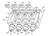
図3に示すように、本実施形態のインク流路弁10では、各インクカートリッジ9b,9c,9m,9yに対応する各インク流路弁10b,10c,10m,10yが並列状態で一体に形成されている。
【0034】
このインク流路弁10は、図3〜図6に示すように、流路形成部材としてのベース部材30を備えている。ベース部材30の基端部には、図6に示すように、管状に形成された取着部31が設けられている。さらに、ベース部材30には、同じく管状に形成された液体流入口としてのインク流入口32が、取着部31と連通するように設けられている。前記取着部31は、上記した中空針11が取着可能となるように構成されている。従って、インク流路弁10には、インクカートリッジ9から中空針11を介してインクを流入することができる。
【0035】
一方、図6に示すようにベース部材30の他端部には、管状に形成された液体流出口としてのインク流出口33が設けられている。このインク流出口33の先端部34には、チューブ等を介して前記記録ヘッド8が取着可能となるように構成されている。このように構成することによって、インク流路弁10内に流入されているインクを、インク流出口33からチューブ等を介して記録ヘッド8に供給することができる。
【0036】
他方、図3に示すように、ベース部材30の一側面(前記押圧部材13の当接部14と対向する面)には、弾性部材としてのエラストマ部材Eが形成されている。本実施形態のエラストマ部材Eは、ベース部材30に対して例えば、二色成形によって形成されている。このエラストマ部材Eには、その長手方向に溝部35(35b,35c,35m,35y)が形成されている。この溝部35は、インク流入口32及びインク流出口33と開閉制御部材としての押圧部材13側にて連通するになっている。
【0037】
前記エラストマ部材Eに溝部35が形成されることによって、インク流路弁10のベース部材30の一側面(前記押圧部材13の当接部14と対向する面)には、同一平面上で開口する開口部36(36b,36c,36m,36y)が形成される。
【0038】
この開口部36には、上記したフィルム15が、図4〜図6に示すように、同開口部36を被覆するように同開口部36の縁部38に溶着されている。このフィルム15は、ガスバリア性及び可撓性を有し、同フィルム15を開口部36の縁部38に溶着することによって、溝部35は封止される。このように構成することによって、インク流路弁10には、インク流入口32、インク流出口33、溝部35によってインク流路12が構成されている。前記フィルム15は、ガスバリア性を有するので、インク流路12内に流入されるインクは、その信頼性の低下を抑制される。
【0039】
一方、フィルム15は、図4及び図5に示すように、一枚に形成されていて、各インク流路弁10b,10c,10m,10yの溝部35の開口部36(36b,36c,36m,36y)を同時に被覆できる大きさとなっている。このフィルム15を開口部36の縁部38に溶着する際には、図4に示すインク流路弁10b及びインク流路弁10yの基端部側に一体に形成された位置決め手段としての突起30aに沿って、前記開口部36を被覆した後に、溶着するようになっている。さらにフィルム15には、図5に示すように、縁部38に溶着された後に、各インク流路弁10(10b,10c,10m,10y)の間に分割手段としてのスリットS1〜S3をベース部材30の長手方向に形成するようになっている。このスリットS1〜S3は、フィルム15を各インク流路弁10b,10c,10m,10yに対応するように、それぞれに分割するためのものでる。
【0040】
このスリットS1〜S3をフィルム15に形成することによって、フィルム15は、各インク流路弁10b,10c,10m,10yに対応するようにフィルム15b,15c,15m,15yに分割されるようになっている。さらに、このスリットS1〜S3は、各フィルム15b,15c,15m,15yが、その両端部(インク流入口32側及びインク流出口33側)において、それぞれ連なるように形成されている。また、上記したように、スリットS1〜S3は、フィルム15を縁部38に溶着した後に形成するようになっている。これによって、スリットS1〜S3の形成位置がずれる等のミスを低減することができる。
【0041】
このように構成することによって、フィルム15が押圧部材13の当接部14(14b,14c,14m,14y)によってそれぞれ押圧された場合、隣り合う各フィルム15b,15c,15m,15yは、スリットS1〜S3によって互いの引っ張り合いを防ぐようになっている。従って、例えば、フィルム15b,15cが押圧部材13(13b,13c)の当接部14(14b,14c)によって、それぞれ押圧されると、フィルム15b,15cはスリットS1によって互いに引っ張り合うのを防ぐことができるになっている。
【0042】
図6に示すように、上記のように構成したフィルム15を、押圧部材13の当接部14が押圧するときには、当接部14はフィルム15を介して、溝部35の底部39(前記インク流路12の底)に当接する。この底部39を含む溝部35は、上記したように、エラストマ部材Eにより形成されていることから可撓性を有し、当接部14の押圧を受けやすくなっている。これによって、フィルム15と底部39は密着するので、インク流路12は封止されるようになっている。そして封止することによって、インク流路弁10は閉弁状態となって、図2に示すインク流路12内でのインクの流動は効果的に封止される。
【0043】
さらに、封止の際には、上記したように、スリットS1〜S3によって、フィルム15(15b,15c,15m,15y)は、互いに引っ張り合うことを防ぐことができる。これによって、フィルム15と底部39はより密着することができ、インク流路12はより効果的に封止されるようになっている。
【0044】
尚、上記した突起30aは、フィルム15を案内し溶着する際の位置を決めるためのものであって、ベース部材30の基端部側に設けたが、この限りではなく、フィルム15を案内できれば、その形状及び形成場所を適宜変更しても良いよい。
【0045】
次に、上記のように構成したプリンタ1の動作について、図7に従って説明する。
図7は、プリンタ1のクリーニング操作を説明するためのグラフ図である。
【0046】
プリンタ1は、印刷時においての印刷不良発生時や、長期間の未使用状態からの復帰の際に、記録ヘッド8に対してクリーニング操作を実行するように設定されている。このクリーニング操作は、まず非印刷領域にキャリッジ5を移動させた後、キャップ部材17によって記録ヘッド8に形成されたノズルNを封止する。
【0047】
次に、プリンタ1は、押圧部材13によって、フィルム15を押圧し、各インク流路弁10(10b,10c,10m,10y)のインクの流動を封止状態にする。
【0048】
この状態から図示しない吸引ポンプを駆動させキャップ部材17とノズル形成面8aから構成される空間内に負圧をかける。これによって、各ノズルNとともに各ノズルNを介して各インク流路弁10に対して負圧がかかる。そして、図7に示すように、予め設定された所定時間T1が経過し、インク流路12に対しての負圧が蓄積され、その負圧が最も上昇したとき、プリンタ1は、押圧部材13によるフィルム15の押圧を解除し、インク流路12を流動状態にする。これによって、インク流路弁10のインク流路12内を流動するインクには蓄積された負圧によって、その流速が瞬間的に上昇する。そして、ノズルNからは、インク流路12に混入した気泡とともに、ノズルN内の増粘したインクが廃インクとして排出される。そして、排出された廃インクは、キャップ部材17内へ落ちる。同廃インクは、チューブ21を通過し廃インクタンクに速やかに廃棄される。これによって、インク流路12内に気泡が混入されている場合であっても、ノズルNから排出することができる。
【0049】
次に、図7に示すように、予め設定された所定時間T2が経過すると、プリンタ1は、吸引ポンプの駆動を停止する。そして、記録ヘッド8からキャップ部材17を離間させ、キャップ部材17内を大気開放させた後、再び記録ヘッド8のノズルNの封止して、クリーニング操作を停止する。
【0050】
これによって、上記したように本実施形態のプリンタ1は、クリーニング操作を行うことで記録ヘッド8のメンテナンスを効果的に行うことができる。
以上、上記した本実施形態によれば、以下の効果を奏する。
【0051】
(1)本実施形態では、フィルム15にスリットS1〜S3を形成し、各インク流路弁10b,10c,10m,10yにそれぞれ対応するように、同フィルム15をフィルム15b,15c,15m,15yに分割した。
【0052】
このスリットS1〜S3を形成することによって、隣り合うフィルム15の引っ張り合いを防ぐことができる。これによって、各フィルム15b,15c,15m,15yは、対応する当接部14b,14c,14m,14yの押圧によって、互いに引っ張り合うこともなく、それぞれ底部39に密着することができる。この結果、各インク流路弁10b,10c,10m,10yは、インク流路12内を流動するインクを効果的に封止することができる。また、フィルム15にスリットS1〜S3を形成するという簡単な構成により、互いに引っ張り合う力を分散することができる。
【0053】
(第2実施形態)
次に、本発明を具体化した第2実施形態について図8に従って説明する。
図8は、本実施形態のインク流路弁の構成を説明するための斜視図である。
【0054】
本実施形態では、第1実施形態と比較してインク流路弁の構成が異なる。本実施形態では、説明の便宜上、第1実施形態と差異のある箇所について説明し、同一の部分については、同一の符号を付して説明を省略する。
【0055】
本実施形態のフィルム15には、図8に示すように、縁部38に溶着された後に、各インク流路弁10(10b,10c,10m,10y)の間に分割手段としての穴部H1〜H3をベース部材30の長手方向に形成するようになっている。この穴部H1〜H3は、第1実施形態のスリットS1〜S3と同様に、フィルム15を各インク流路弁10b,10c,10m,10yに対応するように、それぞれに分割するためのものでる。
【0056】
この穴部H1〜H3をフィルム15に形成することによって、フィルム15は、各インク流路弁10b,10c,10m,10yに対応するようにフィルム15b,15c,15m,15yに分割されるようになっている。さらに、この穴部H1〜H3は、第1実施形態のスリットS1〜S3と同様に、各フィルム15b,15c,15m,15yが、その両端部(インク流入口32側及びインク流出口33側)において、それぞれ連なるように形成されている。さらに、第1実施形態と同様に、穴部H1〜H3は、フィルム15を縁部38に溶着した後に形成するようになっている。これによって、穴部H1〜H3の形成位置がずれる等のミスを低減することができる。
【0057】
このように構成することによって、フィルム15が押圧部材13の当接部14(14b,14c,14m,14y)によってそれぞれ押圧された場合、隣り合う各フィルム15b,15c,15m,15yは、穴部H1〜H3によって互いの引っ張り合いを防ぐようになっている。従って、例えば、フィルム15b,15cが押圧部材13(13b,13c)の当接部14(14b,14c)によって、それぞれ押圧されると、フィルム15b,15cは穴部H1によって互いに引っ張り合うのを防ぐことができる。
【0058】
また、本実施形態の穴部H1〜H3は、第1実施形態のスリットS1〜S3に比べて大きく形成されている。従って、本実施形態のインク流路弁10では、穴部H1〜H3を形成することによって、より隣り合うフィルム15の互いに引っ張り合うことを防ぐことができる。これによって、フィルム15と底部39はより密着することができ、インク流路12はより効果的に封止される。また、フィルム15に穴部H1〜H3を形成するという簡単な構成により、互いに引っ張り合う力を分散することができる。
【0059】
そして、上記したように構成された本実施形態のインク流路弁10を備えたプリンタ1は、第1実施形態と同様にクリーニング操作を行うことで、記録ヘッド8のメンテナンスをより効果的に行うことができる。
【0060】
尚、発明の実施の形態は、上記各実施形態に限定されるものではなく、以下のように変更してもよい。
・上記各実施形態では、フィルム15にスリットS1〜S3若しくは、穴部H1〜H3を形成したが、この限りではなく、押圧部材13による押圧の際に、フィルム15の引っ張り合いを低減できれば、適宜変更してもよい。従って、例えば、各インク流路弁10b,10c,10m,10yの個々にフィルムを溶着してもよい。
【0061】
・上記各実施形態では、押圧部材13(13b,13c,13m,13y)は対応するインク流路弁10(10b,10c,10m,10y)のフィルム15(15b,15c,15m,15y)を同時に押圧するように構成されているが、この限りではなく、例えば、個々のインク流路弁10毎に押圧してもよい。また、押圧部材13を13b,13c,13m,13yというように、対応するインク流路弁10(10b,10c,10m,10y)毎に設けずに、例えば棒状の押圧部材によりフィルム15を同時に押圧するように構成してもよい。
【0062】
・上記各実施形態では、本発明をキャリッジ5にインクカートリッジ9を搭載するオンキャリッジタイプのプリンタに適用したが、カートリッジをキャリッジ以外の場所に配置するいわゆるオフキャリッジタイプのプリンタ(液体噴射装置)に適用してもよい。プリンタ1をオンキャリッジタイプとして構成したが、この限りではなく、オフキャリッジタイプとして構成してもよい。これに応じて、インク流路弁10を適宜変更してもよい。
【0063】
・上記各実施形態では、インクカートリッジ9b,9c,9m,9y、インク流路弁10b,10c,10m,10y、押圧部材13b,13c,13m,13yとしたが、この限りではなく、インクカートリッジ9の数に合わせて、対応するインク流路弁10及び押圧部材13の数を適宜変更してもよい。
【0064】
・上記各実施形態では、液体噴射装置として、プリンタ1について説明したが、他の液体を噴射する液体噴射装置であってもよい。例えば、液晶ディスプレイやELディスプレイ、FED(面発光ディスプレイ)等の製造などに用いられる電極材や色材などの液体を噴射する液体噴射装置、バイオチップ製造に用いられる生体有機物を噴射する液体噴射装置、精密ピペットとしての試料噴射装置であってもよい。
【0065】
・上記各実施形態では、フィルム15を溶着後、スリットS1〜S3又は穴部H1〜H3を形成したが、フィルム15に先にスリットS1〜S3又は穴部H1〜H3を形成してもよい。
【図面の簡単な説明】
【図1】 第1実施形態のプリンタの概略を説明するための斜視図。
【図2】 同実施形態のインク流路を説明するための側面図。
【図3】 同実施形態のインク流路弁の構成を説明するための斜視図。
【図4】 同実施形態のインク流路弁の構成を説明するための斜視図。
【図5】 同実施形態のインク流路弁の構成を説明するための斜視図。
【図6】 同図5におけるA−A線方向の断面図。
【図7】 同プリンタのクリーニング操作を説明するためのグラフ図。
【図8】 第2実施形態のインク流路弁の構成を説明するための斜視図。
【符号の説明】
1…液体噴射装置としてのプリンタ、8…液体噴射ヘッドとしての記録ヘッド、9…液体貯留部としてのインクカートリッジ、10,10b,10c,10m,10y…流路弁としてのインク流路弁、12…流路としてのインク流路、13,13b,13c,13m,13y…開閉制御部材としての押圧部材、15…フィルム部材としてのフィルム、16…クリーニング装置としてのキャップホルダ、30…流路形成部材としてのベース部材、30a…位置決め手段としての突起、32…液体流入口としてのインク流入口、33…液体流出口としてのインク流出口、35,35b,35c,35m,35y…溝部、36…開口部、H1〜H3…穴部、S1〜S3…スリット。[0001]
BACKGROUND OF THE INVENTION
The present invention relates to a flow path valve for effectively performing maintenance of a liquid ejecting head and a liquid ejecting apparatus including the flow path valve.
[0002]
[Prior art]
Conventionally, an ink jet recording apparatus is widely known as a liquid ejecting apparatus. This ink jet recording apparatus supplies ink to a recording head from an ink cartridge via an ink flow path. The supplied ink is ejected as ink droplets from the nozzle openings of the recording head onto recording paper for recording.
[0003]
In general, the ink used in the ink jet recording apparatus is configured by dissolving a coloring component in a volatile ink solvent. Therefore, when the ink solvent evaporates at the nozzle opening, the viscosity of the ink increases and further solidifies. As a result, the nozzle opening may become clogged, resulting in poor printing. Further, when air bubbles are mixed in the ink flow path, the pressure applied to the ink flowing in the ink flow path is changed, so that the ink cannot be accurately discharged from the nozzle opening, which may cause a discharge failure.
[0004]
For this reason, an ink jet recording apparatus usually includes a cleaning device for eliminating clogging. In this type of cleaning device, when the nozzle opening of the ink jet recording apparatus is clogged, the nozzle forming surface of the recording head is sealed by the cap means, and the negative pressure from the suction pump causes a high viscosity or solidification from the nozzle opening. A cleaning operation is performed to suck out and discharge the used ink.
[0005]
When this cleaning operation is executed, it is effective to generate an ink flow as fast as possible in the ink flow path from the ink reservoir of the ink cartridge to the nozzle opening. With this, bubbles existing in the flow path can be discharged together with the thickened ink.
[0006]
Therefore, an ink channel valve that can be opened and closed is disposed in the ink channel between the ink reservoir and the recording head. When the ink suction is started via the capping means in the cleaning operation, the ink flow path valve is closed. Various liquid ejecting apparatuses that are configured to instantaneously increase the flow velocity of ink in the ink flow path by opening the ink flow path valve when the negative pressure in the capping means rises have been proposed ( For example, Patent Document 1).
[0007]
The ink flow path valve of
[0008]
[Patent Document 1]
Japanese Patent Laid-Open No. 2001-113726
[Problems to be solved by the invention]
However, in the configuration of the ink flow path valve of
[0010]
The present invention has been made to solve the above problems, and a first object of the present invention is to provide a flow path valve that can improve the reliability of the flow path valve opening and closing operations. There is. In addition to the first object, a second object of the present invention is to provide a liquid ejecting apparatus that includes the flow path valve and that effectively performs maintenance of the liquid ejecting head.
[0011]
[Means for Solving the Problems]
The flow path valve of the present invention comprises, in the flow path forming member, a liquid inlet, a liquid outlet, and a plurality of liquid flow paths communicating with the liquid inlet and the liquid outlet in parallel. A flow path valve that can open or close the liquid flow path as necessary, and communicates with the liquid inlet and the liquid outlet on one side of the flow path forming member. A plurality of openings that are opened on the same plane by the respective groove portions of the respective elastic members are formed in parallel by providing the elastic members in which the groove portions are formed so as to individually correspond to the respective liquid flow paths; Each liquid flow path is formed by covering each elastic member with one film member so as to cover each opening , and is disposed outside the liquid flow path so as to face the film member. The opening / closing control member is in contact with the film member and By pressing the Lum member to the elastic member side, with to the liquid flow path in a closed state, the film member, corresponding to the film member to each liquid channel between the liquid flow path adjacent to each other Thus, a dividing means for dividing each was formed.
[0012]
According to this, even if the film member is pressed by the opening / closing control member, it is not pulled by the dividing means. Therefore, the force by which the opening / closing control member presses each liquid flow path can be made uniform, and the film member can be more closely attached to each groove. As a result, each flow path valve can more effectively seal the liquid flowing in the liquid flow path. Therefore, the reliability of the opening and closing operations of the flow path can be improved.
[0013]
The flow path valve dividing means is a slit formed in the film member between the liquid flow paths adjacent to each other.
According to this, the film members are not pulled with each other by a simple configuration of slits formed in the film member.
[0014]
The flow path valve dividing means is a hole formed in the film member between the liquid flow paths adjacent to each other.
According to this, the film members are not pulled together by a simple configuration of the hole formed in the film member.
[0015]
The flow path valve is provided with positioning means on the flow path forming member for positioning the film member when the elastic members are covered with the film member.
According to this, when the film member is coated on each elastic member on the plurality of liquid flow paths by the positioning means, the film member can be easily positioned and covered.
[0016]
The positioning means of the flow path valve is a protrusion formed integrally with the flow path forming member.
According to this, the positioning means can be easily provided only by integrally forming the protrusion on the flow path forming member.
[0017]
In the liquid ejecting apparatus including the flow path valve according to the aspect of the invention, the liquid inflow port is connected to a liquid storage unit side that stores liquid, and the liquid outflow port is connected to a liquid ejecting head side that ejects liquid And a cleaning device that closes the flow path with the flow path valve, seals the flow of the liquid to the liquid ejecting head, and then applies a negative pressure to the liquid ejecting head for cleaning. It was.
[0018]
According to this, the film member is pressed by the opening / closing control member, and the flow path valve is closed. Then, a negative pressure is applied to the liquid ejecting head by the cleaning device, and the flow path valve is opened when the negative pressure increases. Thereby, the flow velocity of the liquid in the flow path can be instantaneously increased via the liquid ejecting head. Accordingly, the liquid ejecting apparatus can discharge bubbles and the like from the liquid ejecting head, and therefore can perform maintenance of the liquid ejecting head more effectively.
[0019]
DETAILED DESCRIPTION OF THE INVENTION
(First embodiment)
A first embodiment of the present invention will be described below with reference to FIGS.
[0020]
FIG. 1 is a perspective view for explaining an outline of the printer of the present embodiment. FIG. 2 is a side view for explaining the ink flow path of the present embodiment.
As shown in FIG. 1, a
[0021]
A guide member 4 is installed on the frame 2 so as to be parallel to the
[0022]
A
[0023]
Further, as shown in FIG. 1, the
[0024]
The ink supplied from the ink cartridge 9 (9b, 9c, 9m, 9y) via the ink flow path valve 10 (10b, 10c, 10m, 10y) is pressurized by the
[0025]
On the other hand, as shown in FIG. 2, the
[0026]
In the
[0027]
The
[0028]
In the
[0029]
As shown in FIG. 2, the
[0030]
The
[0031]
That is, when the suction pump is operated at the time of sealing the nozzle N by the
[0032]
Next, the configuration of the ink
3 to 5 are perspective views for explaining the configuration of the ink
[0033]
As shown in FIG. 3, in the ink
[0034]
As shown in FIGS. 3 to 6, the ink
[0035]
On the other hand, as shown in FIG. 6, the other end portion of the
[0036]
On the other hand, as shown in FIG. 3, an elastomer member E as an elastic member is formed on one side surface of the base member 30 (a surface facing the
[0037]
By forming the groove portion 35 in the elastomer member E, an opening is formed on one side surface (a surface facing the
[0038]
As shown in FIGS. 4 to 6, the
[0039]
On the other hand, as shown in FIGS. 4 and 5, the
[0040]
By forming the slits S1 to S3 in the
[0041]
With this configuration, when the
[0042]
As shown in FIG. 6, when the
[0043]
Furthermore, at the time of sealing, as described above, the films 15 (15b, 15c, 15m, 15y) can be prevented from being pulled together by the slits S1 to S3. As a result, the
[0044]
The
[0045]
Next, the operation of the
FIG. 7 is a graph for explaining the cleaning operation of the
[0046]
The
[0047]
Next, the
[0048]
From this state, a suction pump (not shown) is driven to apply a negative pressure in the space formed by the
[0049]
Next, as shown in FIG. 7, when a predetermined time T2 set in advance elapses, the
[0050]
Accordingly, as described above, the
As mentioned above, according to this embodiment mentioned above, there exist the following effects.
[0051]
(1) In the present embodiment, slits S1 to S3 are formed in the
[0052]
By forming the slits S <b> 1 to S <b> 3, it is possible to prevent the
[0053]
(Second Embodiment)
Next, a second embodiment of the present invention will be described with reference to FIG.
FIG. 8 is a perspective view for explaining the configuration of the ink flow path valve of the present embodiment.
[0054]
In the present embodiment, the configuration of the ink flow path valve is different from that in the first embodiment. In the present embodiment, for the sake of convenience of explanation, portions that are different from the first embodiment will be described, and the same portions will be denoted by the same reference numerals and description thereof will be omitted.
[0055]
In the
[0056]
By forming the holes H1 to H3 in the
[0057]
By comprising in this way, when the
[0058]
Further, the holes H1 to H3 of the present embodiment are formed larger than the slits S1 to S3 of the first embodiment. Therefore, in the ink
[0059]
And the
[0060]
In addition, embodiment of invention is not limited to said each embodiment, You may change as follows.
In each of the above embodiments, the slits S1 to S3 or the holes H1 to H3 are formed in the
[0061]
In each of the above embodiments, the pressing member 13 (13b, 13c, 13m, 13y) simultaneously applies the film 15 (15b, 15c, 15m, 15y) of the corresponding ink flow path valve 10 (10b, 10c, 10m, 10y). However, the present invention is not limited to this. For example, each ink
[0062]
In each of the above embodiments, the present invention is applied to an on-carriage type printer in which the
[0063]
In each of the above embodiments, the ink cartridges 9b, 9c, 9m, and 9y, the ink
[0064]
In each of the above embodiments, the
[0065]
In each of the above embodiments, the slits S1 to S3 or the holes H1 to H3 are formed after the
[Brief description of the drawings]
FIG. 1 is a perspective view for explaining an outline of a printer according to a first embodiment.
FIG. 2 is a side view for explaining an ink flow path of the embodiment.
FIG. 3 is a perspective view for explaining a configuration of an ink flow path valve according to the embodiment.
FIG. 4 is a perspective view for explaining a configuration of an ink flow path valve according to the embodiment.
FIG. 5 is a perspective view for explaining the configuration of the ink flow path valve of the embodiment.
6 is a cross-sectional view taken along line AA in FIG.
FIG. 7 is a graph for explaining a cleaning operation of the printer.
FIG. 8 is a perspective view for explaining the configuration of an ink flow path valve according to a second embodiment.
[Explanation of symbols]
DESCRIPTION OF
Claims (6)
前記流路形成部材の一側面には、前記液体流入口及び前記液体流出口と連通する溝部が形成された弾性部材を前記各液体流路と個別対応するように設けることにより、該各弾性部材の前記各溝部によって同一平面上に開口する複数の開口部が並列形成されると共に、
前記各液体流路は、前記各開口部を覆うように一枚のフィルム部材を前記各弾性部材に被覆することで形成され、
前記液体流路外に前記フィルム部材と対向するように配置される開閉制御部材が、前記フィルム部材に当接して同フィルム部材を前記弾性部材側に押圧することにより、前記液体流路を閉弁状態にさせるとともに、
前記フィルム部材に、互いに隣り合う前記液体流路間で前記フィルム部材を前記各液体流路に対応するようにそれぞれ分割する分割手段を形成したことを特徴とする流路弁。The flow path forming member includes a liquid inlet, a liquid outlet, and a plurality of liquid flow paths communicating with the liquid inlet and the liquid outlet in parallel, and the liquid flow path as necessary. Is a flow path valve that can be opened or closed,
On each side surface of the flow path forming member, an elastic member in which a groove portion communicating with the liquid inlet and the liquid outlet is formed so as to individually correspond to each liquid flow path. A plurality of openings that open on the same plane are formed in parallel by each of the grooves, and
Each liquid channel is formed by covering each elastic member with a single film member so as to cover each opening ,
An open / close control member disposed so as to face the film member outside the liquid channel closes the liquid channel by contacting the film member and pressing the film member toward the elastic member. As well as
2. A flow path valve according to claim 1, wherein splitting means is formed in the film member to divide the film member between the liquid flow paths adjacent to each other so as to correspond to the liquid flow paths .
前記分割手段は、前記フィルム部材に、互いに隣り合う前記液体流路間に形成したスリットである流路弁。The flow path valve according to claim 1,
The dividing means is a flow path valve which is a slit formed in the film member between the liquid flow paths adjacent to each other.
前記分割手段は、前記フィルム部材に、互いに隣り合う前記液体流路間に形成した穴部である流路弁。The flow path valve according to claim 1,
The dividing means is a flow path valve that is a hole formed in the film member between the liquid flow paths adjacent to each other.
前記フィルム部材を、前記各弾性部材に被覆する際に位置決めをするための位置決め手段を前記流路形成部材上に設けたことを特徴とする流路弁。In the flow path valve according to any one of claims 1 to 3,
A flow path valve characterized in that positioning means for positioning the film member when covering each elastic member is provided on the flow path forming member.
前記位置決め手段は、前記流路形成部材に一体成形された突起である流路弁。The flow path valve according to claim 4,
The flow path valve, wherein the positioning means is a protrusion formed integrally with the flow path forming member.
前記液体流入口は、液体を貯留する液体貯留部側に接続され、
前記液体流出口は、液体を噴射する液体噴射ヘッド側に接続されるとともに、
前記流路弁にて流路を閉弁状態とし、前記液体噴射ヘッドへの前記液体の流動を封止した後、前記液体噴射ヘッドに負圧をかけてクリーニングするクリーニング装置を備えたことを特徴とする液体噴射装置。A liquid ejecting apparatus comprising the flow path valve according to any one of claims 1 to 5,
The liquid inflow port is connected to a liquid storage part side for storing a liquid,
The liquid outlet is connected to a liquid ejecting head that ejects liquid,
A cleaning device is provided that closes the flow path with the flow path valve, seals the flow of the liquid to the liquid ejecting head, and then applies a negative pressure to the liquid ejecting head for cleaning. A liquid ejecting apparatus.
Priority Applications (1)
| Application Number | Priority Date | Filing Date | Title |
|---|---|---|---|
| JP2003202424A JP4172348B2 (en) | 2003-07-28 | 2003-07-28 | Flow path valve and liquid ejecting apparatus including the flow path valve |
Applications Claiming Priority (1)
| Application Number | Priority Date | Filing Date | Title |
|---|---|---|---|
| JP2003202424A JP4172348B2 (en) | 2003-07-28 | 2003-07-28 | Flow path valve and liquid ejecting apparatus including the flow path valve |
Publications (2)
| Publication Number | Publication Date |
|---|---|
| JP2005041082A JP2005041082A (en) | 2005-02-17 |
| JP4172348B2 true JP4172348B2 (en) | 2008-10-29 |
Family
ID=34262148
Family Applications (1)
| Application Number | Title | Priority Date | Filing Date |
|---|---|---|---|
| JP2003202424A Expired - Fee Related JP4172348B2 (en) | 2003-07-28 | 2003-07-28 | Flow path valve and liquid ejecting apparatus including the flow path valve |
Country Status (1)
| Country | Link |
|---|---|
| JP (1) | JP4172348B2 (en) |
Families Citing this family (1)
| Publication number | Priority date | Publication date | Assignee | Title |
|---|---|---|---|---|
| JP2007313806A (en) * | 2006-05-29 | 2007-12-06 | Hitachi Industrial Equipment Systems Co Ltd | Inkjet recorder |
Family Cites Families (1)
| Publication number | Priority date | Publication date | Assignee | Title |
|---|---|---|---|---|
| JP2001038925A (en) * | 1999-08-02 | 2001-02-13 | Seiko Epson Corp | Ink jet recording apparatus and cleaning control method in the apparatus |
-
2003
- 2003-07-28 JP JP2003202424A patent/JP4172348B2/en not_active Expired - Fee Related
Also Published As
| Publication number | Publication date |
|---|---|
| JP2005041082A (en) | 2005-02-17 |
Similar Documents
| Publication | Publication Date | Title |
|---|---|---|
| JP2007230227A (en) | Liquid ejection apparatus and initial filling method of the same | |
| JP5217338B2 (en) | Droplet ejector | |
| JP4375340B2 (en) | Liquid ejector | |
| US7950764B2 (en) | Pressure regulating mechanism and liquid ejecting apparatus | |
| US8534815B2 (en) | Flow path member, liquid ejecting head, and liquid ejecting apparatus | |
| JP4821817B2 (en) | Droplet ejector | |
| JP5024324B2 (en) | Liquid ejecting apparatus and liquid filling method in liquid ejecting apparatus | |
| US6843557B2 (en) | Liquid jetting device and liquid supplying method in use for the liquid jetting device | |
| JP4099763B2 (en) | Liquid suction device and liquid jet device of liquid jet head | |
| JP3873675B2 (en) | ink cartridge | |
| JP2005288767A (en) | Liquid ejector | |
| JP4802493B2 (en) | Liquid ejector | |
| JP4172348B2 (en) | Flow path valve and liquid ejecting apparatus including the flow path valve | |
| JP2005041048A (en) | Liquid injection apparatus and liquid vessel | |
| JP4379465B2 (en) | Liquid ejector | |
| JP4165322B2 (en) | Flow path valve and liquid ejecting apparatus including the flow path valve | |
| JP4600094B2 (en) | Valve device and liquid injection device | |
| JP4211516B2 (en) | Flow path valve and liquid ejecting apparatus having the flow path valve | |
| US20050104924A1 (en) | Liquid ejecting apparatus | |
| US20060278577A1 (en) | Liquid flow promoter device and liquid ejection apparatus | |
| JP6090611B2 (en) | Channel member, liquid ejecting head, and liquid ejecting apparatus | |
| JP4935922B2 (en) | Liquid ejector | |
| JP2005271377A (en) | Head cleaning method of liquid jetting apparatus and liquid jetting apparatus | |
| JP2004299292A (en) | Liquid injection device | |
| JP2006075998A (en) | Liquid jetting apparatus and liquid suction device of liquid jetting head |
Legal Events
| Date | Code | Title | Description |
|---|---|---|---|
| A621 | Written request for application examination |
Free format text: JAPANESE INTERMEDIATE CODE: A621 Effective date: 20050531 |
|
| A977 | Report on retrieval |
Free format text: JAPANESE INTERMEDIATE CODE: A971007 Effective date: 20071129 |
|
| A131 | Notification of reasons for refusal |
Free format text: JAPANESE INTERMEDIATE CODE: A131 Effective date: 20080430 |
|
| A521 | Written amendment |
Free format text: JAPANESE INTERMEDIATE CODE: A523 Effective date: 20080627 |
|
| TRDD | Decision of grant or rejection written | ||
| A01 | Written decision to grant a patent or to grant a registration (utility model) |
Free format text: JAPANESE INTERMEDIATE CODE: A01 Effective date: 20080722 |
|
| A01 | Written decision to grant a patent or to grant a registration (utility model) |
Free format text: JAPANESE INTERMEDIATE CODE: A01 |
|
| A61 | First payment of annual fees (during grant procedure) |
Free format text: JAPANESE INTERMEDIATE CODE: A61 Effective date: 20080804 |
|
| R150 | Certificate of patent or registration of utility model |
Free format text: JAPANESE INTERMEDIATE CODE: R150 |
|
| FPAY | Renewal fee payment (event date is renewal date of database) |
Free format text: PAYMENT UNTIL: 20110822 Year of fee payment: 3 |
|
| FPAY | Renewal fee payment (event date is renewal date of database) |
Free format text: PAYMENT UNTIL: 20120822 Year of fee payment: 4 |
|
| LAPS | Cancellation because of no payment of annual fees |