JP4172202B2 - Image forming apparatus and color misregistration control method - Google Patents
Image forming apparatus and color misregistration control method Download PDFInfo
- Publication number
- JP4172202B2 JP4172202B2 JP2002128838A JP2002128838A JP4172202B2 JP 4172202 B2 JP4172202 B2 JP 4172202B2 JP 2002128838 A JP2002128838 A JP 2002128838A JP 2002128838 A JP2002128838 A JP 2002128838A JP 4172202 B2 JP4172202 B2 JP 4172202B2
- Authority
- JP
- Japan
- Prior art keywords
- image forming
- color
- color misregistration
- forming unit
- specific
- Prior art date
- Legal status (The legal status is an assumption and is not a legal conclusion. Google has not performed a legal analysis and makes no representation as to the accuracy of the status listed.)
- Expired - Fee Related
Links
- 238000000034 method Methods 0.000 title claims description 38
- 238000001514 detection method Methods 0.000 claims description 130
- 239000003086 colorant Substances 0.000 claims description 41
- 238000011144 upstream manufacturing Methods 0.000 claims description 12
- 230000015572 biosynthetic process Effects 0.000 claims description 6
- 230000000007 visual effect Effects 0.000 claims description 2
- 239000000463 material Substances 0.000 description 17
- 238000010586 diagram Methods 0.000 description 11
- 238000003860 storage Methods 0.000 description 7
- 230000032258 transport Effects 0.000 description 4
- 230000007613 environmental effect Effects 0.000 description 3
- 238000002310 reflectometry Methods 0.000 description 3
- 239000006260 foam Substances 0.000 description 2
- 238000005187 foaming Methods 0.000 description 2
- 230000006870 function Effects 0.000 description 2
- 238000004519 manufacturing process Methods 0.000 description 2
- 229920003002 synthetic resin Polymers 0.000 description 2
- 239000000057 synthetic resin Substances 0.000 description 2
- 238000002834 transmittance Methods 0.000 description 2
- 239000004642 Polyimide Substances 0.000 description 1
- 241000519995 Stachys sylvatica Species 0.000 description 1
- 239000002131 composite material Substances 0.000 description 1
- 229920001940 conductive polymer Polymers 0.000 description 1
- 230000000694 effects Effects 0.000 description 1
- 230000002093 peripheral effect Effects 0.000 description 1
- 239000000049 pigment Substances 0.000 description 1
- 229920001721 polyimide Polymers 0.000 description 1
- 230000007261 regionalization Effects 0.000 description 1
- 230000000630 rising effect Effects 0.000 description 1
- 238000005070 sampling Methods 0.000 description 1
- 238000003466 welding Methods 0.000 description 1
Images

Classifications
-
- G—PHYSICS
- G03—PHOTOGRAPHY; CINEMATOGRAPHY; ANALOGOUS TECHNIQUES USING WAVES OTHER THAN OPTICAL WAVES; ELECTROGRAPHY; HOLOGRAPHY
- G03G—ELECTROGRAPHY; ELECTROPHOTOGRAPHY; MAGNETOGRAPHY
- G03G15/00—Apparatus for electrographic processes using a charge pattern
- G03G15/01—Apparatus for electrographic processes using a charge pattern for producing multicoloured copies
-
- G—PHYSICS
- G03—PHOTOGRAPHY; CINEMATOGRAPHY; ANALOGOUS TECHNIQUES USING WAVES OTHER THAN OPTICAL WAVES; ELECTROGRAPHY; HOLOGRAPHY
- G03G—ELECTROGRAPHY; ELECTROPHOTOGRAPHY; MAGNETOGRAPHY
- G03G2215/00—Apparatus for electrophotographic processes
- G03G2215/01—Apparatus for electrophotographic processes for producing multicoloured copies
- G03G2215/0151—Apparatus for electrophotographic processes for producing multicoloured copies characterised by the technical problem
- G03G2215/0158—Colour registration
- G03G2215/0161—Generation of registration marks
Landscapes
- Physics & Mathematics (AREA)
- General Physics & Mathematics (AREA)
- Color Electrophotography (AREA)
- Laser Beam Printer (AREA)
- Control Or Security For Electrophotography (AREA)
- Facsimile Scanning Arrangements (AREA)
- Fax Reproducing Arrangements (AREA)
Description
【0001】
【発明の属する技術分野】
本発明は、プリンタや複写機などの画像形成装置等に関し、より詳しくは、各色の画像を形成する複数の記録装置を備えた画像形成装置等に関する。
【0002】
【従来の技術】
従来、用紙等の一つの記録媒体に各色の画像を重ねて形成するカラープリンタやカラー複写機等の画像形成装置が広く用いられている。これらの画像形成装置では、複数の画像形成部によって形成される各色の色ずれ(位置ずれ)が問題となる。この色ずれは、例えば、各色毎に設けられる複数の画像形成部を転写ベルトに対向して並べて配置する所謂タンデム方式を採用する場合に、画像形成部の各取り付け位置の誤差、各画像形成部の周速誤差、転写ベルトに対する露光位置の違い、転写ベルトの線速の変化等により発生する。即ち、例えば、タンデム方式を採用する画像形成装置の場合には、各色毎に設けられる画像形成部のアライメントや機械的誤差等がそのまま記録媒体(用紙等)上での色ずれとなる。従って、このような方式を採用する画像形成装置では、これらの色ずれ量を測定し、色ずれの発生を抑制するための色ずれ制御(レジストレーションコントロール)が不可欠となる。
【0003】
この色ずれ制御として、例えば特開平8−248721号公報には、Y(イエロー),M(マゼンタ),C(シアン),K(ブラック)の各色のマークを転写ベルトに描き、その位置をセンサで読み取ると共に、その読取結果から色ずれを算出して画像書き込み部を制御する技術が開示されている。
【0004】
一方、今後のカラープリンタの動向として、上述した常用色(通常色)であるY,M,C,Kの4色のフルカラープリンタに対し、この4色では表現が困難または不可能であった特定色等の画形材を用いた画像をこのフルカラープリンタにて形成することが検討されている。例えば、特定ユーザ専用のコーポレートカラー、点字用の発泡トナー、蛍光色、光沢を向上させるトナー等である。この従来のY,M,C,K4色に対し、これらの特定色にて印字を行う際には、上述したタンデム方式の場合には、この特定カラー等を印字するための特定色画像形成部を通常の色を印字する画像形成部に並べて配置することが必要となる。
【0005】
【発明が解決しようとする課題】
ここで、このような特定色等の画形材にて画像を形成する特定色画像形成部を配置した場合にあっても、上述した色ずれ制御が必要となる。しかしながら、特定色は、Y,M,C,Kの通常色とはその取り扱いが異なることから、単に色を増やして色ずれ制御を実行すれば良いといった簡単なものではない。例えば、追加される特定色の使用頻度が低い場合に、この特定色に対しても通常色と同様に色ずれ制御を実行することは好ましくない。特に、これらの特定色は、一般にトナー(画形材)の料金が高いことから、頻繁に色ずれ制御を実行すると、トナー(画形材)の無駄な消費によるコストアップが無視できないものとなる。
【0006】
また、例えば、特定色として点字用の発泡トナーを例に挙げると、この発泡トナーの印字については、通常色の印字に比べて位置精度の要求が低いことから、かかる要求位置精度の低いトナー(画形材)に対して通常色と同様な色ずれ制御を実行することは無駄な制御となってしまう。更には、特定色により形成された画像では、従来から用いられていたセンサをそのまま用いただけでは読み取れない場合がある。また、色自体はセンサで読み取ることが可能であっても、例えば転写ベルトにパターンを形成した後に、転写ベルトとの関係でこのセンサでは読み取ることのできない(転写ベルトと特定色とが区別できない)場合も生じる。
【0007】
本発明は、以上のような技術的課題を解決するためになされたものであって、その目的とするところは、複数の画像形成部における色ずれ制御に際し、画像形成部の特徴に合わせて好ましい色ずれ制御を実行することにある。
また他の目的は、常用の色以外に特定色用の画像形成部を搭載した画像形成装置において、好ましい色ずれ制御を実行することにある。
【0008】
【課題を解決するための手段】
かかる目的のもと、本発明では、例えばタンデム方式を採用するフルカラー装置等の画像形成装置において、例えば、Y,M,C,K等の常用色に対する色ずれ制御と、特定色を含む色ずれ制御とを区別して実施している。即ち、本発明は、画像を形成するa個(aは3以上の整数)の画像形成部を用いて画像を重ね転写する画像形成装置であって、第1の色ずれ制御手段では、b個(b<a、bは2以上の整数)の画像形成部を用いて色ずれ制御を実行し、第2の色ずれ制御手段では、この第1の色ずれ制御手段とは異なる条件によって、第1の色ずれ制御手段により色ずれ制御が行われないa−b個の画像形成部における一部または全部を含んで色ずれ制御を実行することを特徴としている。
【0009】
ここで、第2の色ずれ制御手段は、a−b個の画像形成部を使用するジョブに基づいて色ずれ制御を実行することを特徴とすることができる。例えば、a−b個の画像形成部が特定色の画像を形成するものである場合に、この特定色を使用するジョブの前、この特定色のジョブの数回に1回の前などに色ずれ制御を実行することができる。
【0010】
また、この第1の色ずれ制御手段および第2の色ずれ制御手段にてセンサの検出レベルおよび/または色ずれ検出用パターンを切り換える切り換え手段を更に含めることができる。この切り換え手段としては、例えば特定色を読む際にセンサのゲイン、光量等を切り換えたり、特定色を読む際にパターン検知時のスレッシュホールドレベルを切り換えたりするものが挙げられる。
【0011】
また、本発明は、各色の画像を形成する複数の画像形成部を有し、これらの画像形成部によって形成される画像を重ね転写する画像形成装置であって、所定の転写体に対し複数の画像形成部を用いて色ずれ検出用パターンを形成する制御部と、この制御部によって転写体に形成された色ずれ検出用パターンを読み込むパターン検出センサとを含み、この制御部は、複数の画像形成部のうち特定の画像形成部に対しては転写体への色ずれ検出用パターンの形成を行わないことを特徴とすることができる。ここで転写体とは、中間転写体のみならず、シート材を搬送する転写材搬送体(例えば用紙搬送ベルト等)をも含めるものである。以下、同様である。
【0012】
ここで、制御部は、複数の画像形成部のうち特定の画像形成部に対しては、他と異なった条件にて転写体への色ずれ検出用パターンの形成を行うことを特徴とすれば、この特定の画像形成部における使用状況等に合わせて適宜、色ずれ検出用パターンの形成を行うことができる点で好ましい。
【0013】
また、この制御部は、転写体における他の画像形成部が色ずれ検出用パターンを形成する領域に特定の画像形成部による色ずれ検出用パターンを置き換えて形成することを特徴とすれば、例えば色ずれ検出用パターンの形成領域が狭い場合等であっても、特定の画像形成部による色ずれ検出用パターンを形成することができる点で好ましい。
【0014】
更に、この制御部は、パターン画像の形成を行わない特定の画像形成部の割り当て領域を空白領域として転写体に対して他の複数の画像形成部による色ずれ検出用パターンを形成することを特徴とすることができる。また更に、この特定の画像形成部に対して転写体への色ずれ検出用パターンの形成を行う際には、この空白領域に対して形成することを特徴とすることができる。これらによれば、特定の画像形成部による色ずれ検出用パターンの有無によって、パターン形成のためのアルゴリズムを大きく変更する必要がない点で優れている。
【0015】
他の観点から捉えると、本発明が適用される画像形成装置は、転写部に対して各々並んで配置され、Y(イエロー)、M(マゼンタ)、C(シアン)、K(ブラック)の画像を形成する常用画像形成部と、この常用画像形成部による画像形成の順序に対して常用画像形成部の上流側および/または下流側に配置され、特定色の画像を形成する特定色画像形成部と、常用画像形成部および/または特定色画像形成部を用いて色ずれ制御を行う制御部とを含んでいる。
【0016】
ここで、この特定色画像形成部は、特定色が明るい色である場合に、常用画像形成部の上流側に配置されることを特徴とすれば、最初のプリントアウト速度を早くすることができる点で好ましい。また、特定色画像形成部は、特定色が暗い色である場合に、常用画像形成部によって形成される明るい色の画像上に色ずれ検出用パターンを形成することを特徴とすることができる。
【0017】
更に、転写部は、特定色画像形成部により形成される色ずれ検出用パターンの描画領域を他の領域と区別して設けることを特徴とすることができる。例えば、この色ずれ検出用パターンの描画領域に対して、色や透過率、反射率などを変えることで、他の領域と区別することができる。
【0018】
一方、本発明は、画像を形成するa個(aは3以上の整数)の画像形成部を用いて画像を重ねて転写する画像形成装置の色ずれ制御方法であって、b個(b<a、bは2以上の整数)の画像形成部を用いて色ずれ検出用パターンを形成する第1のステップと、この第1のステップとは異なる条件によって、第1のステップによって色ずれ検出が行われないa−b個の画像形成部における一部または全部を用いて色ずれ検出用パターンを形成する第2のステップとを含む。
【0019】
ここで、この第2のステップにより形成される色ずれ検出用パターンは、シビアな設定を必ずしも必要としない場合には、粗調整のための専用パターン、ユーザによって実行される目視チャートのためのパターンとすることができる。
【0020】
【発明の実施の形態】
以下、添付図面に示す実施の形態に基づいて、本発明を詳細に説明する。
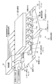
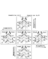
図1は本実施の形態が適用される画像形成装置を示した図である。この画像形成装置は、電子写真方式を採用した所謂タンデム型のデジタルカラー機であり、イエロー(Y)、マゼンタ(M)、シアン(C)、ブラック(K)の如き各色の画像を形成する常用画像形成部11Y,11M,11C,11K、および特定色の画像を形成する特定色画像形成部11Sを含む画像形成部11、これらの画像形成部11に対して静電潜像を形成する露光装置13、例えば画像形成部11に接触し、画像形成部11により形成された画像を重ねて搬送する中間転写体としての転写ベルト21を備えている。また、転写ベルト21の内側には、この転写ベルト21を駆動する駆動ロール22、画像形成部11の感光体に対向して複数、設けられ、転写ベルト21上に画像を形成するための一次転写ロール23、転写ベルト21上に形成されたカラー画像を用紙(記録シート)等の記録媒体に転写する二次転写ロール24、転写ベルト21に対する一次転写位置を特定するためのバックアップロール25を備えている。また、露光装置13および画像形成部11に対して色ずれ検出用のパターン情報を供給する制御部31、転写ベルト21の所定領域に形成された色ずれ検出用パターンを読み取るパターン検出センサ32を備えている。
【0021】
この画像形成部11は、常用画像形成部11Y,11M,11C,11K、および特定色画像形成部11Sの各々に、異なる色のトナーによって像を形成するための現像装置と、この現像装置から供給されるトナーによって形成される画像を担持する感光体ドラム等からなる像担持体、その他、感光体ドラムを帯電させる帯電装置、残留トナーを除去するクリーナ等の各種画像形成ユニットが備えられている。ここで、イエロー(Y)、マゼンタ(M)、シアン(C)、ブラック(K)の如き、通常のカラー表現に頻繁に用いられる色を常用色とするならば、この常用色ではなく、通常のカラー画像形成には用いられない特定色(特殊な画形材)の画像を特定色画像形成部11Sにて形成することができる。この特定色(特殊な画形材)としては、例えば、特定ユーザ専用のコーポレートカラー(例えば特定フィルム会社の緑色、特定ドリンク会社の赤など)や、点字用の発泡トナー、蛍光色、光沢を向上させるトナー等が挙げられる。この特定色画像形成部11Sの現像装置には、所定の特定色トナーが保有されている。尚、常用色としては、上述したY,M,C,Kの4色のほかに、ダークイエローなどを含めた6色以上を常用色とすることもできる。また、上述の例から明らかなように、特定色とは、色が特別なものだけに限定されるものではなく、常用色として、通常のカラー画像形成に用いられるもの以外の材質、特性等を有する特殊な画形材を含めるものである。即ち、特定色画像形成部11Sは、通常色に用いられる画像形成部11に対して、オプション用の画像形成部11とも言うことができる。
【0022】
露光装置13は、例えばレーザROS(Raster Output Scanner)やLEDアレイ等からなり、各々の画像形成部11が有する感光体に対して静電潜像形成のための光を照射させている。この露光装置13には、例えば画像読取装置(IIT)や外部のパーソナルコンピュータ装置(PC)等から得られ、画像処理装置(図示せず)によって変換されたデジタル画像信号が、制御部31を介して各色別に供給される。また、ユーザによる特定色の指定等によって、特定色画像形成部11Sに対するデジタル画像信号の書き込みが行われる。また、露光装置13には、制御部31によって生成された色ずれ検出用のパターン画像が供給される。このパターン画像は、各色についての画像書き込み位置の制御信号として、各画像形成部11に対応する露光装置13に供給される。パターン画像の書き込み位置としては、例えば、転写ベルト21の移動方向に直交する両端であって記録媒体への画像形成に関与しない部分等に、転写ベルト21の移動方向に対して各色毎に所定の間隔を隔てて印字される。制御部31からは、この書き込み位置に基づき、各色毎にタイミング等が設定されて、制御信号が供給される。
【0023】
パターン検出センサ32は、例えば不透明な転写ベルト21上に形成された色ずれ検出用パターン(ラダー状トナーパッチ、シェブロンパッチ)を検出器上に結像し、パッチの重心線と検出器の中心線とが一致したときにパルスを出力する反射型センサである。この検出器は、90度の角度に配置された2組のBi−Cell(2分割ダイオード)で構成されている。パターン検出センサ32は、各画像形成部11で形成されたパッチによる色ずれ検出用パターンの相対色ずれを検出するために、最下流側の常用画像形成部11Kの下流側で、且つ副走査方向に垂直な軸上に2個、配置されている。パターン検出センサ32の発光部は、例えば赤外LED(波長880nm)が2個用いられ、安定したパルス出力を確保するために、2個のLEDの発光光量を調整(例えば2段階)できるように構成されている。
【0024】
転写ベルト21としては、例えば、可撓性を有するポリイミド等の合成樹脂フィルムを帯状に形成し、この帯状に形成された合成樹脂フィルムの両端を溶着等の手段によって接続することによって、無端ベルト状に形成したものが用いられる。例えば導電性を備える必要があるときには、導電性のポリマー等が用いられ、転写ベルト21の表面は黒っぽくなる。この転写ベルト21は、駆動ロール22とバックアップロール25とによって、略直線的に張られ、この略直線的な部分に対して、略水平方向に一定間隔を隔てて、画像形成部11および対向する一次転写ロール23が配列されている。図1に示す例では、転写ベルト21の移動方向に対して、転写作業を行う際の上流側に特定色画像形成部11Sを備え、下流方向に順に、イエローの常用画像形成部11Y、マゼンタの常用画像形成部11M、シアンの常用画像形成部11C、黒の常用画像形成部11Kが配列されている。一般に、特定色は常用色に比べて使用される頻度が低い。この使用頻度の低い特定色画像形成部11Sを最下流側に設けた場合には、特定色画像形成部11Sの存在する領域を通過する時間だけ、最初のプリントアウト速度が遅くなる。そこで、特定色を印字可能にした画像形成装置において最初のプリントアウト速度を改善するためには、特定色画像形成部11Sを上流側に配置することが好ましい。但し、転写ベルト21の色と特定色との関係等から、上流側に配置することが好ましくない場合もある(後述)。
【0025】
転写ベルト21には、ベルトの動きによって、画像形成部11によって形成された各色の画像が順に重ね合わされる。重ね合わされ、転写ベルト21上に形成されたカラートナー画像は、図示しない記録媒体(記録シート)の搬送とタイミングが合わされて、二次転写ロール24の位置にて記録媒体に転写される。カラートナー画像が転写された記録媒体は、図示しない定着装置に搬送され、カラートナー画像が記録媒体に定着されて、画像形成装置に設けられた排出トレイに排出される。
【0026】
ここで、本実施の形態では、転写ベルト21上に、色の異なる複数の画像形成部11によって位置ずれ検出用パターンが順次形成され、この位置ずれ検出用パターンがパターン検出手段であるパターン検出センサ32によって検出されることで、重ね合わされるカラー画像に対する位置ずれ分の補正を可能としている。
【0027】
このとき、本実施の形態では、特定色画像形成部11S対する位置ずれ制御を、常用画像形成部11Y,11M,11C,11Kに対する位置ずれ制御とは区別して取り扱っている点に特徴がある。即ち、画像形成部11の個数をa個(aは3以上の整数、図1の例では5個)とすると、通常の位置ずれ制御に際しては、b個(bは2以上の整数、b<a、図1の例では4個(11Y,11M,11C,11K))の画像形成部11によって色ずれ制御を行う。色ずれ制御が行われなかったa−b個(図1の例では、1個、11S)については、b個の色ずれ制御とは別個の所定タイミングにて、色ずれ制御を実行するように構成した。尚、a−b個が1つではなく2以上の複数個である場合には、その一部だけ、または全部を含んで色ずれ制御を行うことも可能である。
【0028】
この図1に示すような特定色画像形成部11Sによって画像形成される特定色は、常用色(通常色)に比べて一般に使用頻度が低く、この特定色に対しても常用色と同様に色ずれ制御を実行することは好ましくない。特に、これらの特定色は、製造量が少ないことから製造コストが非常に高く、頻繁に色ずれ制御を実行すると、トナーの無駄な消費によるコストアップが無視できないものとなる。また、例えば、特定色として点字用の発泡トナーを例に挙げると、この発泡トナーの印字については、常用色の印字に比べて位置精度の要求が低く、常用色と同様な色ずれ制御を実行することは無駄な制御となってしまう。そこで、特定色画像形成部11Sの色ずれ制御については、常用画像形成部11Y,11M,11C,11Kの色ずれ制御とは異なる所定のタイミングで実行することが好ましい。
【0029】
制御部31は、この所定のタイミングによって、特定色画像形成部11Sを用いた色ずれ検出用のパターン形成のための位置制御信号を露光装置13および画像形成部11に対して出力する。この所定のタイミングとは、例えば、上述したa−b個の画像形成部11の中に含まれる特定色画像形成部11Sを使うジョブの前、またはそのジョブの数回に1回の前などであり、間引きをして自動調整を行うことができる。また、通常のb個の常用画像形成部11Y,11M,11C,11Kの色ずれ制御の数回に一度、前回実施から日付変更時に1回、数時間または数日に1回など、間引きして自動調整を実施することができる。更に、この間引き頻度は、例えばユーザの好みや、特定色の種類等に応じて、任意に設定することも可能である。
【0030】
また、特定色画像形成部11Sを用いた色ずれ制御は、この特定色画像形成部11Sが交換されたとき、即ち、上述したa−b個の中に含まれる特定色の画像形成ユニットまたはそのパーツ(電子写真方式を採用していない場合には、インクジェットヘッド、サーマルヘッド、感光体、現像器、露光装置13など)が交換されたときに実行することができる。更に、前回の色ずれ調整を実施してからある所定レベル以上の環境変動(例えば5℃以上の温度上昇)があった場合、所定の値以上の振動衝撃(例えば5G以上の振動)があった場合、特定のインターロックのオープン(装置のドアの開閉)があった場合などに実施するように構成することができる。また更に、ユーザ(サービス担当者を含む)からの調整実施要求コマンドの入力があった場合や、複数のプロセス速度を有する場合にそのプロセス速度を切り換えた場合などにも、それらのタイミングを所定のタイミングとして、a−b個の中に含まれる特定色の色ずれ制御を実行させることが可能である。
【0031】
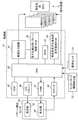
図2は、制御部31の機能を説明するためのブロック図である。制御部31は、タンデム型のデジタルカラー機の画像形成動作および色ずれの検出や校正動作などを制御するCPU40、CPU40からの指令に基づいて画像情報あるいは色ずれ検出パターンを形成するための画像を出力する画像出力回路41、色ずれ検出用パターンの画像情報を予め記憶した色ずれ検出用パターン格納ROM42、CPU40が実行する画像形成動作や色ずれの検出および校正動作などを制御するためのソフトウェアプログラムを記憶したROM43を備えている。また、上述したような特定色色ずれ検出用の各種条件を格納する特定色色ずれ検出用条件格納ROM44を備えている。画像出力回路41からは、Y,M,C,Kの常用色を形成する常用画像形成部11Y,11M,11C,11Kに対応する露光装置13のROS(Y用ROS,M用ROS,C用ROS,K用ROS)に対して画像情報や色ずれ検出用パターンの情報が出力されると共に、特定色である特定色画像形成部11Sに対応する露光装置13のROS(特定色用ROS)に対して画像情報や色ずれ検出用パターンの情報が出力される。特定色色ずれ検出用条件格納ROM44には、常用色の色ずれ検出とは異なった閾値によって色ずれ検出を行うための値も格納されている。
【0032】
また、制御部31は、各種カウンタ値や、ジョブの回数、前回の色ずれ検出処理の実行情報(時間情報等)を格納するRAM45、パターン検出センサ32の発光部33(例えば赤外LED)を点灯するLEDドライバ46、パターン検出センサ32の受光部34でデータをサンプリングするための閾値を制御するPWM(パルス幅変調)回路47、パターン検出センサ32の受光部34から出力される色ずれ検出用パターン検出時の所定のパルス間(立ち上がり)の時間間隔を基準クロックパルスに基づいて計測するカウンタ48を備えている。尚、制御部31のCPU40には、例えば温度センサや湿度センサ等からなる環境センサ51、画像形成装置におけるドアの開閉を検出するインターロック開閉検出部52等の外部からの各種信号が入力される。尚、PWM(パルス幅変調)回路47の代わりに他の制御方法を採用することも可能である。
【0033】
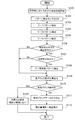
図3は、制御部31にて実行される色ずれ制御の処理を示したフローチャートである。制御部31は、所定のタイミングにて、常用色(Y,M,C,K)に対する色ずれ検出処理を開始する(ステップ101)。色ずれ制御の処理を開始するタイミングとしては、例えば、装置の電源ON、インターロック開閉検出部52からのインターロックオープン信号受信時、スリープモード解除時、ジャム除去時、前回色ずれ制御を実施した時点から日付が変更したとき等、装置構成などによって任意に設定することができる。また、例えば、環境センサ51から得られる温度情報にて、前回色ずれ制御を実施したときからの温度変化量が所定の温度(例えば4℃)上昇したときに実施するように構成することもできる。この色ずれ検出処理では、まず、パターン検出センサ32をONさせ(ステップ102)、C(シアン)−Y(イエロー)パターンの検出(ステップ103)、C(シアン)−M(マゼンタ)パターンの検出(ステップ104)、C(シアン)−K(黒)パターンの検出(ステップ105)が実行される。
【0034】
その後、特定色色ずれ検出用条件格納ROM44の内容を参照して、特定色の色ずれ検出処理の開始条件に合致したか否かが判断される(ステップ106)。この開始条件(開始タイミング)としては、前述したように、常用色に対する処理とは異なった条件とすることができる。例えば、温度上昇が常用色の実施条件よりも高い、例えば6℃上昇したとき、常用色の色ずれ処理の数回に1回、数日に1回等、間引きして行うようにすることもできる。ステップ106にて特定色の色ずれ検出条件に合致しない場合には、特定色についての色ずれ制御を省略して、ステップ109に移行する。ステップ106にて条件に合致する場合には、特定色の存在を確認し(ステップ107)、存在しない場合には、ステップ109へ移行し、存在する場合には、特定色の色ずれ検出処理に移行して、C(シアン)−特定色のパターン検出が実行される(ステップ108)。
【0035】
このステップ108でのC(シアン)−特定色のパターン検出では、特定色色ずれ検出用条件格納ROM44に格納された条件に基づいて、常用色の検出とは異なった条件にて検出するように構成することができる。例えば、特定色が常用色の検出と同じ条件では検出ができない画形材である場合には、検出のための条件を変える必要がある。具体的には、パターン検出センサ32のパターン検知時におけるスレッシュホールドレベルを変えること、パターン検出センサ32のゲイン、光量、光源波長・光源部のフィルタ、光源の種類、受光波長・受光部のフィルタ、検出素子を切り換えること、パターンの種類を変えることなどがある。また、例えば蛍光顔料などでは、紫外光源のセンサを使用することが好ましいことから、パターン検出センサ32として複数のセンサを搭載する場合には、これらのセンサを切り換えることなどが挙げられる。
【0036】
その後、検出された各パターンに基づいて、各ブロックの色ずれ量が算出される(ステップ109)。そして、有効ブロック数の判定がなされ(ステップ110)、OKであれば、有効ブロックデータが平均化され(ステップ111)、補正量の演算がなされた後、実際の補正が実行され(ステップ112)、処理が終了する。ステップ110で有効ブロック数判定がNGであれば、補正は実施せずに失敗(fail)の情報を例えばRAM45に登録し(ステップ113)、処理が終了する。ここで、ステップ110にて実行される有効ブロック数の判定としては、例えば、組み合わせブロックの測定可能な個数が、ある個数以上か否か等が挙げられる。
【0037】
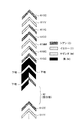
図4は、形成される色ずれ検出用パターンを説明するための図である。図4に示すように、複数の山形マーク61が、例えば転写ベルト21の両端における非画像領域に形成される。ここでは、基準となる第1の色からなる第1番目の山形マーク61CCと、被測定色である第2の色からなる第2番目の山形マーク61YYと、第1の色と第2の色からなる3番目の山形マーク61YCとの3つの山形マーク61を一つの単位として、被測定色の全てを組み合わせたパターンが用いられる。また、本実施の形態では、特定色に対する色ずれ検出のための空白部62を備えている(後に詳述する)。
【0038】
ここで、これらの山形マーク61は、転写ベルト21に書き込まれることから、例えば転写ベルト21を黒色等の暗色(反射率の低い色)で形成した場合には、パターン検出センサ32を用いて黒(K)のトナーによる山形マーク61を検出するのが困難になる。そこで、黒(K)の山形マーク61を形成する部分(周辺)に対しては、明るい色(反射率の高い色)である例えばイエロー(Y)のトナーを用いた下地を予め形成しておき、この下地の上に黒(K)等の暗色のトナーによる山形マーク61を形成する。そして、その形成された山形マーク61の切れ目から観測される下地の位置ずれを測定することで、黒(K)等の暗色の位置ずれを把握することが可能となる。
【0039】
図5は、パターン検出センサ32を用いた色ずれ検出の原理を説明するための図である。図5の▲3▼は、理想的なパッチ配置を示しており、色ずれ量はゼロである。このとき、サイドAおよびサイドBの双方で発生するパルス出力の間隔(TAa、TAb、TBa、TBb)は何れも等しくなる。一方、図5の▲2▼および▲4▼は、主走査方向にずれが生じている例であり、ずれ量がゼロのときに比べてパルス出力の間隔がそれぞれ変化する。また、図5の▲1▼および▲5▼は、副走査方向にずれた例であり、ずれ量がゼロのときに比べてパルス出力の間隔がそれぞれ変化する。実際の色ずれは、主走査方向および副走査方向に独立して同時に発生することから、図5の複合となるが、これらの色ずれは、主走査・副走査方向の2色間の色ずれを副走査方向のパッチ通過タイミング差で検出することが可能である。
【0040】
次に、転写ベルト21に対する各画像形成部11の配置について説明する。例えば転写ベルト21が黒に近い色で、測定対象の色が暗い色である場合に、例えば、図1に示すように、転写ベルト21の移動方向の上流側に明るい色の画像形成部11を設けることができれば、このような暗い色の色ずれを容易に検出することができる。図1に示す例では、上流側に明るい色であるイエロー(Y)の画像形成部11Yが設けられ、その下流方向側に黒(K)の画像形成部11Kが設けられていることから、予めイエロー(Y)の画像を下地にして、黒(K)による色ずれ検出用パターンを形成すれば、色ずれ検出が容易にできる。
【0041】
尚、下地を形成した後に他の色のパターンを形成する方法は、特定色についても適用することができる。例えば転写ベルト21の色が黒であり(黒に近い色を含む、反射率が低い色)、特定色が暗い色である場合等、特定色が転写ベルト21の色に近い色である場合には、例えば、黒である転写ベルト21の上に、下地となるイエロー(Y)を敷き、その上に暗い色である特定色のパターンを重ねて描くのである。このようにすれば、特定色が転写ベルト21と同様に反射率の低いものであっても、色ずれ制御を行うことが可能となる。但し、かかる方法を採用するに際し、例えば、図1に示すように特定色画像形成部11Sが転写ベルト21の移動方向の最も上流側にある場合には、イエロー(Y)の常用画像形成部11Yによる画像を下地として特定色画像形成部11Sによりパターンを重ねることはできない。そこで、特定色が転写ベルト21の色に近い色である場合には、上述した最初のプリントアウト速度を犠牲にして、画像形成部11の下流側に特定色画像形成部11Sを設けることが好ましい。更に、これらの考え方を拡張して、例えば複数の特定色を形成するために特定色画像形成部11Sを複数個、設ける場合には、この複数個の特定色画像形成部11Sを、転写ベルト21との関係を加味して、その明るさの度合いに応じて上流側および/または下流側に配置することが可能である。
【0042】
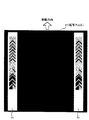
また、特定色が暗い色で、この特定色を形成する特定色画像形成部11Sを上流側に設ける必要があり、且つ、転写ベルト21が黒(黒に近い色、反射率が低い色)である場合には、図6に示すように、転写ベルト21の例えば両端に、反射率の高い、例えば白色系の色である色ずれ検出用パターンの描画領域71を設け、この描画領域71に暗い色の特定色を含む色ずれ検出用パターンを描くように構成した。この図6は、描画領域71を設けた転写ベルト21の一部を示した図である。このように構成することにより、例えば、特定色と転写ベルト21とが共に反射率の低い場合であっても、パターン検出センサ32によって特定色の色ずれ制御が可能となる。尚、図6に示す例では、転写ベルト21の両端について反射率を変えているが、例えば、常用色であるb個の色ずれ検出用パターンを描く箇所と、特定色であるa−b個の色ずれ検出用パターンを描く箇所とを変えて、このa−b個のパターンが乗る領域は、それ以外の領域と色、透過率、または反射率などを変えるように構成することも可能である。また、図6に示すように、転写ベルト21の移動方向に直交する方向の両端以外に、例えば転写ベルト21の中央部に同様な描画領域71を設けるように構成することも可能である。
【0043】
ここで、本実施の形態では、その一つの例として、図4に示すように、常用色の色ずれ制御を行うに際して形成される色ずれ検出用パターンに、特定色用のパターンが入る部分を空白とした空白部62を設けている。上述のように、常用色(Y,M,C,K)の色ずれ制御は比較的頻繁に行われるが、特定色については、例えば間引きによって色ずれ制御の頻度を低くしている。このとき、特定色の色ずれ制御を行うにあたって、新たな検出アルゴリズムを設けることは、アルゴリズムの複雑化の観点から好ましくない。そこで、図4に示す例では、空白部62を設け、特定色についての色ずれ制御を省略するときには、その部分の領域を空白にすることで、検出のためのアルゴリズムの複雑化を回避している。即ち、a個の画像形成部11を有する画像形成装置で、常用色であるb個の色ずれ制御を行う際には、a−b個の画像形成部11が入る部分は空白として色ずれ検出用パターンを形成するのである。従って、この空白部分は、少なくとも、特定色の色ずれが検出できる単位(例えば特定色が1つであれば、例えば3つの山形マーク61が入るスペース等)が確保される。
【0044】
尚、このような空白部分を設けずに、例えば、常用色の山形マーク61の一部を置き換えて、その常用色の一部の代わりに、特定色の山形マーク61を描くことも可能である。例えば、各画像形成部11に設けられる感光体が小さい場合には、この色ずれ検出用パターンを細かいピッチで入れる必要があり、かかる場合には、特定色用の空白部62を設けることは好ましくない。また、例えば、画像情報と次の画像情報との間の狭い領域(インターイメージと呼ぶ)を利用して色ずれ制御を行う場合にも、特定色用の空白部62を設けることは好ましくない。従って、これらの場合にあっても、その常用色の一部の代わりに、特定色の山形マーク61を描くように構成することが好ましい。
【0045】
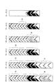
図7、図8は、色ずれ検出用パターンの例を示した図である。図7は転写ベルト21が黒色(反射率が低い)である場合のパターン例を示し、図8は転写ベルト21が白色(反射率が高い)である場合のパターン例を示している。図7に示すケース1およびケース2は、Y,M,C,Kの常用色検出用パターン75に加えて特定色の色ずれを検出する特定色検出用パターン76を付加した場合を示しており、ケース1では特定色が暗い色である場合、ケース2は特定色が明るい色である場合を示している。ケース3、ケース4、およびケース5は、ケース3の常用色検出用パターン75に置き換えて特定色検出用パターン76を形成する例が示されている。ケース4は、特定色が暗い色であることから、黒(K)に置き換えて特定色検出用パターン76が形成され、ケース5では、例えばマゼンタ(M)に置き換えて特定色検出用パターン76が形成されている。ケース6では、画像形成部11として特定色と黒色(K)だけを使用する画像形成装置において、特定色が明るい色である場合を示している。かかる場合では、特定色を下地にして、黒色(K)が重ねられ、色ずれ検出用パターンが生成される。
【0046】
一方、図8に示す転写ベルト21が白色である場合において、ケース7では、特定色が暗い色で、特定色と黒色(K)だけを使用する画像形成装置における色ずれ検出用パターンが示されている。ケース8では、特定色が明るい色であり、黒色(K)の上に特定色のパッチが形成され、色ずれ制御が実行される。ケース9〜ケース11では、特定色が暗い色であり、画像形成部11の最上流に特定色画像形成部11Sがある場合を示している。ここでは、特定色を下地にして、各色のパッチが形成される。ケース9にはY,M,C,Kの常用色と特定色とのパッチが全て示されており、ケース10は特定色を除く4色、ケース11は常用色である黒色(K)を除いて色ずれ検出用パターンを形成する例が示されている。このケース9〜ケース11では、白抜けとなる部分で特定色の色ずれを検出することが可能である。
【0047】
以上、詳述したように、本実施の形態によれば、従来の色ずれ制御では検出できなかった特定色(特殊な画形材)に対しても色ずれ制御を実施することができる。このときに、例えば、特定色に対して、またはその特定色のいくつか、または全てに対して色ずれ制御を実施するか否かをユーザが選択可能に構成しても良い。この選択は、画像形成装置に設けられる例えばコントロールパネル等から指示することができる。また、特定色に対する使用頻度を画像形成装置が学習し、例えば、全ての画像形成部11に対して色ずれ制御を実施するのか、常用色についてのみ実施するのか、特定色について実施するのか等を自動選択するように構成することも可能である。
【0048】
また、本実施の形態では、反射型センサであるパターン検出センサ32を用い、トナー等の画形材における反射率と、転写ベルト21の反射率とに基づいて、色ずれ検出用パターンの描き方を選択して色ずれ制御を行うことが可能である。例えば、ベルト上に単独でパターンを描く方法や、反射率の高い色を下地に敷き、その上に反射率の低い色でこの下地の一部が見えるマスクをする方法、反射率の低い色を下地に敷き、その上に反射率の高い色でパターンを描く方法等である。このとき、a個の画像形成部11のうち、a−b個の特定色等の画像形成部11が暗い色(低反射率)か明るい色(高反射率)かは、例えば、特定色画像形成部11Sまたはトナーボトル、またはインクカートリッジなどに、その色材の情報が書き込まれたメモリを有し、その情報を制御部31が認識して自動判別する方法が挙げられる。また、特定色画像形成部11Sまたはトナーボトル、またはインクカートリッジなどが装着されたことを検知した後、画像出力前に制御部31により特定色のパッチを出力し、そのパッチをパターン検出センサ32で検知し、このパターン検出センサ32の出力値から自動的に判別する方法がある。更に、極端に反射率の高い色材の場合には、形成されるパターンを低濃度で形成するなどの方法も採用することが可能である。
【0049】
尚、本実施の形態では、中間転写体としての転写ベルト21を用いたが、この転写ベルト21上の記録シートを搬送させ、各色の画像を直接、記録シート上に転写させる、例えば用紙搬送ベルト等の転写体(ここでは転写材搬送体)に対して色ずれ検出用パターンを形成するように構成することもできる。また、転写ベルト21上だけではなく、記録シート上に色ずれ検出用パターンを形成するように構成することも可能である。更に、本実施の形態は、電子写真方式の他、インクジェット方式、サーマルヘッド方式などの画像形成方式における特定色の色ずれ調整にも適用することができる。また、常用する色については電子写真方式で、特定色についてはインクジェット方式で等、ハイブリッドなどの新形態に対して本実施の形態を適用することもできる。
【0050】
【発明の効果】
以上、詳述したように、本発明によれば、複数の画像形成部における色ずれ制御に際し、画像形成部の特徴に合わせて好ましい色ずれ制御を実行することができる。
【図面の簡単な説明】
【図1】 本実施の形態が適用される画像形成装置を示した図である。
【図2】 制御部の機能を説明するためのブロック図である。
【図3】 制御部にて実行される色ずれ制御の処理を示したフローチャートである。
【図4】 形成される色ずれ検出用パターンを説明するための図である。
【図5】 パターン検出センサを用いた色ずれ検出の原理を説明するための図である。
【図6】 描画領域を設けた転写ベルトの一部を示した図である。
【図7】 転写ベルトが黒色である場合のパターン例を示した図である。
【図8】 転写ベルトが白色である場合のパターン例を示した図である。
【符号の説明】
11…画像形成部、13…露光装置、21…転写ベルト、22…駆動ロール、23…一次転写ロール、24…二次転写ロール、25…バックアップロール、31…制御部、32…パターン検出センサ、33…発光部、34…受光部、40…CPU、41…画像出力回路、42…色ずれ検出用パターン格納ROM、43…ROM、44…特定色色ずれ検出用条件格納ROM、45…RAM、46…LEDドライバ、47…PWM(パルス幅変調)回路、48…カウンタ、51…環境センサ、52…インターロック開閉検出部、61…山形マーク、62…空白部、71…描画領域、75…常用色検出用パターン、76…特定色検出用パターン[0001]
BACKGROUND OF THE INVENTION
The present invention relates to an image forming apparatus such as a printer or a copying machine, and more particularly to an image forming apparatus including a plurality of recording devices that form images of respective colors.
[0002]
[Prior art]
2. Description of the Related Art Conventionally, image forming apparatuses such as color printers and color copying machines that form images of respective colors on a single recording medium such as paper have been widely used. In these image forming apparatuses, a color shift (position shift) of each color formed by a plurality of image forming units becomes a problem. For example, when the so-called tandem system in which a plurality of image forming units provided for each color is arranged so as to face the transfer belt is adopted, the color misregistration is caused by an error in each mounting position of the image forming unit, and each image forming unit. Due to a peripheral speed error, a difference in exposure position with respect to the transfer belt, a change in linear velocity of the transfer belt, and the like. That is, for example, in the case of an image forming apparatus that employs a tandem method, the alignment of the image forming unit provided for each color, mechanical error, and the like are the color shifts on the recording medium (paper etc.) as they are. Therefore, in an image forming apparatus employing such a method, color misregistration control (registration control) for measuring the amount of color misregistration and suppressing the occurrence of color misregistration is essential.
[0003]
As this color misregistration control, for example, Japanese Patent Laid-Open No. 8-248721 discloses Y (yellow), M (magenta), C (cyan), and K (black) marks on a transfer belt, and the position of the sensor is indicated by a sensor. And a technique for controlling the image writing unit by calculating a color shift from the reading result.
[0004]
On the other hand, as a trend of color printers in the future, the above-mentioned full-color printers of Y, M, C, and K, which are the normal colors (ordinary colors) described above, are difficult or impossible to express with these four colors. It has been studied to form an image using an image material such as a color by this full-color printer. For example, a corporate color dedicated to a specific user, a foaming toner for Braille, a fluorescent color, a toner for improving gloss, and the like. When printing with these specific colors for these conventional Y, M, C, K4 colors, in the case of the tandem method described above, a specific color image forming unit for printing this specific color or the like Must be arranged side by side in an image forming unit that prints normal colors.
[0005]
[Problems to be solved by the invention]
Here, even in the case where a specific color image forming unit that forms an image with such a shape material of a specific color is disposed, the above-described color misregistration control is required. However, since the specific color is handled differently from the normal colors of Y, M, C, and K, it is not a simple matter that the color misregistration control is simply performed by increasing the number of colors. For example, when the frequency of use of a specific color to be added is low, it is not preferable to perform color misregistration control for the specific color as in the case of the normal color. In particular, these specific colors generally have a high toner (image forming material) fee, so if color misregistration control is executed frequently, the cost increase due to wasteful consumption of toner (image forming material) cannot be ignored. .
[0006]
Further, for example, when a foamed toner for Braille is taken as an example of a specific color, since the requirement for positional accuracy is lower for printing of this foamed toner than for printing of a normal color, the toner ( It is wasteful to perform color misregistration control similar to normal colors on the image forming material. Furthermore, there are cases where an image formed with a specific color cannot be read by using a sensor that has been used conventionally. Also, even if the color itself can be read by a sensor, for example, after forming a pattern on the transfer belt, it cannot be read by this sensor due to the relationship with the transfer belt (the transfer belt and the specific color cannot be distinguished). Sometimes it happens.
[0007]
The present invention has been made in order to solve the technical problems as described above. The object of the present invention is preferably in accordance with the characteristics of the image forming unit in color misregistration control in a plurality of image forming units. It is to execute color misregistration control.
Another object is to perform preferable color misregistration control in an image forming apparatus equipped with an image forming unit for a specific color in addition to a normal color.
[0008]
[Means for Solving the Problems]
For this purpose, in the present invention, in an image forming apparatus such as a full-color apparatus that employs a tandem method, for example, color misregistration control for regular colors such as Y, M, C, and K, and color misregistration including a specific color. It is implemented separately from control. That is, the present invention is an image forming apparatus that superimposes and transfers an image using a (a is an integer of 3 or more) image forming units for forming an image. Color misregistration control is executed using an image forming unit (b <a, b is an integer equal to or greater than 2), and the second color misregistration control unit uses a different condition from that of the first color misregistration control unit. The color misregistration control is executed by including a part or all of the ab image forming units in which the color misregistration control is not performed by one color misregistration control unit.
[0009]
Here, the second color misregistration control unit can perform color misregistration control based on a job using ab image forming units. For example, when a-b image forming units form an image of a specific color, the color is changed before a job that uses the specific color, or once before the job of the specific color. Deviation control can be executed.
[0010]
The first color misregistration control means and the second color misregistration control means may further include a switching means for switching the sensor detection level and / or the color misregistration detection pattern. As this switching means, for example, a sensor gain, light amount, etc. are switched when reading a specific color, or a threshold level at the time of pattern detection is switched when reading a specific color.
[0011]
Further, the present invention is an image forming apparatus that has a plurality of image forming units that form images of each color, and that superimposes and transfers the images formed by these image forming units. A control unit that forms a color misregistration detection pattern using the image forming unit; and a pattern detection sensor that reads the color misregistration detection pattern formed on the transfer body by the control unit. The control unit includes a plurality of images. A color misregistration detection pattern is not formed on a transfer body for a specific image forming portion among the forming portions. Here, the transfer body includes not only an intermediate transfer body but also a transfer material transport body (for example, a paper transport belt) that transports a sheet material. The same applies hereinafter.
[0012]
Here, the control unit is characterized in that for a specific image forming unit among the plurality of image forming units, a color misregistration detection pattern is formed on the transfer body under different conditions. It is preferable in that a color misregistration detection pattern can be appropriately formed in accordance with the usage situation in the specific image forming unit.
[0013]
In addition, if the control unit is formed by replacing a color misregistration detection pattern by a specific image forming unit in a region where another image forming unit in the transfer body forms a color misregistration detection pattern, for example, Even when the color misregistration detection pattern forming area is narrow, it is preferable in that a color misregistration detection pattern can be formed by a specific image forming unit.
[0014]
Further, the control unit forms a pattern for color misregistration detection by a plurality of other image forming units on the transfer body, with an allocation area of a specific image forming unit that does not form a pattern image as a blank area. It can be. Furthermore, when the color misregistration detection pattern is formed on the transfer body with respect to the specific image forming portion, the pattern can be formed in the blank area. According to these, it is excellent in that an algorithm for pattern formation does not need to be changed greatly depending on the presence or absence of a color misregistration detection pattern by a specific image forming unit.
[0015]
From another viewpoint, the image forming apparatuses to which the present invention is applied are arranged side by side with respect to the transfer unit, and images of Y (yellow), M (magenta), C (cyan), and K (black) are provided. And a specific color image forming unit that is arranged on the upstream side and / or downstream side of the normal image forming unit with respect to the order of image formation by the normal image forming unit and forms a specific color image And a control unit that performs color misregistration control using the regular image forming unit and / or the specific color image forming unit.
[0016]
Here, if the specific color image forming unit is arranged on the upstream side of the regular image forming unit when the specific color is a bright color, the initial printout speed can be increased. This is preferable. The specific color image forming unit may form a color misregistration detection pattern on a bright color image formed by the regular image forming unit when the specific color is a dark color.
[0017]
Further, the transfer unit may be characterized in that a drawing area of the color misregistration detection pattern formed by the specific color image forming unit is provided separately from other areas. For example, the color misregistration detection pattern drawing region can be distinguished from other regions by changing the color, transmittance, reflectance, and the like.
[0018]
The present invention, on the other hand, is a color misregistration control method for an image forming apparatus that transfers images by superimposing them using a (a is an integer of 3 or more) image forming units that form images, and b (b < The first step of forming a color misregistration detection pattern using an image forming unit (a and b is an integer of 2 or more) and color misregistration detection by the first step under conditions different from those of the first step. And a second step of forming a color misregistration detection pattern using part or all of the ab image forming units that are not performed.
[0019]
Here, the color misregistration detection pattern formed by the second step is a pattern for a coarse chart, a pattern for a visual chart executed by the user when severe settings are not necessarily required. It can be.
[0020]
DETAILED DESCRIPTION OF THE INVENTION
Hereinafter, the present invention will be described in detail based on embodiments shown in the accompanying drawings.
FIG. 1 is a diagram illustrating an image forming apparatus to which the exemplary embodiment is applied. This image forming apparatus is a so-called tandem type digital color machine adopting an electrophotographic method, and forms an image of each color such as yellow (Y), magenta (M), cyan (C), and black (K).
[0021]
The
[0022]
The
[0023]
The
[0024]
As the
[0025]
The image of each color formed by the
[0026]
Here, in the present embodiment, a misregistration detection pattern is sequentially formed on the
[0027]
At this time, the present embodiment is characterized in that the misregistration control for the specific color
[0028]
The specific color image-formed by the specific color
[0029]
The
[0030]
Further, the color misregistration control using the specific color
[0031]
FIG. 2 is a block diagram for explaining the function of the
[0032]
The
[0033]
FIG. 3 is a flowchart showing color misregistration control processing executed by the
[0034]
Thereafter, referring to the content of the specific color misregistration detection
[0035]
In the pattern detection of C (cyan) -specific color in step 108, the detection is performed under conditions different from the detection of normal colors based on the conditions stored in the specific color misregistration detection
[0036]
Thereafter, the color misregistration amount of each block is calculated based on each detected pattern (step 109). Then, the number of effective blocks is determined (step 110), and if OK, the effective block data is averaged (step 111), the correction amount is calculated, and the actual correction is executed (step 112). , The process ends. If the number of valid blocks is determined to be NG in step 110, the correction is not performed and failure information is registered in, for example, the RAM 45 (step 113), and the process ends. Here, the determination of the number of effective blocks executed in step 110 includes, for example, whether or not the measurable number of combination blocks is greater than or equal to a certain number.
[0037]
FIG. 4 is a diagram for explaining a color misregistration detection pattern to be formed. As shown in FIG. 4, a plurality of angle marks 61 are formed, for example, in non-image areas at both ends of the
[0038]
Here, since these chevron marks 61 are written on the
[0039]
FIG. 5 is a diagram for explaining the principle of color misregistration detection using the
[0040]
Next, the arrangement of the
[0041]
Note that the method of forming a pattern of another color after the base is formed can also be applied to a specific color. For example, when the color of the
[0042]
Further, the specific color is a dark color, and it is necessary to provide the specific color
[0043]
Here, in this embodiment, as an example, as shown in FIG. 4, a portion where a pattern for a specific color is included in a color misregistration detection pattern formed when performing color misregistration control for a regular color. A
[0044]
Without providing such a blank portion, for example, it is possible to replace a part of the regular color chevron mark 61 and draw the chevron mark 61 of a specific color instead of a part of the regular color. . For example, when the photosensitive member provided in each
[0045]
7 and 8 are diagrams showing examples of color misregistration detection patterns. FIG. 7 shows an example pattern when the
[0046]
On the other hand, when the
[0047]
As described above in detail, according to the present embodiment, color misregistration control can be performed even for a specific color (special drawing material) that could not be detected by conventional color misregistration control. At this time, for example, the user may be able to select whether or not to perform color misregistration control for a specific color, or for some or all of the specific colors. This selection can be instructed from, for example, a control panel provided in the image forming apparatus. In addition, the image forming apparatus learns the use frequency for a specific color, and for example, whether color misregistration control is performed for all
[0048]
In the present embodiment, the
[0049]
In this embodiment, the
[0050]
【The invention's effect】
As described above in detail, according to the present invention, when performing color misregistration control in a plurality of image forming units, preferable color misregistration control can be executed in accordance with the characteristics of the image forming units.
[Brief description of the drawings]
FIG. 1 is a diagram illustrating an image forming apparatus to which the exemplary embodiment is applied.
FIG. 2 is a block diagram for explaining functions of a control unit.
FIG. 3 is a flowchart showing color misregistration control processing executed by a control unit.
FIG. 4 is a diagram for explaining a color misregistration detection pattern to be formed.
FIG. 5 is a diagram for explaining the principle of color misregistration detection using a pattern detection sensor.
FIG. 6 is a view showing a part of a transfer belt provided with a drawing region.
FIG. 7 is a diagram illustrating an example of a pattern when a transfer belt is black.
FIG. 8 is a diagram illustrating a pattern example when a transfer belt is white.
[Explanation of symbols]
DESCRIPTION OF
Claims (12)
前記Y、M、C、Kとは異なる特定色の画像形成ユニットを有する特定色画像形成部と、
前記常用画像形成部を用いて色ずれ制御を実行する第1の色ずれ制御手段と、
前記第1の色ずれ制御手段による色ずれ制御の実行条件とは別の、当該第1の色ずれ制御手段による色ずれ制御の実行回数より少なくなる条件に基づき、前記特定色画像形成部を用いて色ずれ制御を実行する第2の色ずれ制御手段と
を含む画像形成装置。 A regular image forming section having image forming units of two or more colors among Y ( yellow ) , M ( magenta ) , C ( cyan ) , and K ( black ) ;
A specific color image forming unit having an image forming unit of a specific color different from Y, M, C, and K;
First color misregistration control means for performing color misregistration control using the regular image forming unit ;
The specific color image forming unit is used based on a condition that is less than the number of executions of the color misregistration control by the first color misregistration control unit, which is different from the execution condition of the color misregistration control by the first color misregistration control unit. And a second color misregistration control means for executing color misregistration control.
前記第1の色ずれ制御手段は、当該第1の色ずれ制御手段が色ずれ検出用パターンを形成する場合であって前記第2の色ずれ制御手段が色ずれ検出用パターンを形成しない場合には、前記特定色画像形成部の割り当て領域を空白領域として前記転写体に対して前記常用画像形成部による前記色ずれ検出用パターンを形成することを特徴とする請求項1記載の画像形成装置。 The first color misregistration control unit and the second color misregistration control unit form a color misregistration detection pattern on a predetermined transfer body when executing each color misregistration control,
The first color misregistration control unit is a case where the first color misregistration control unit forms a color misregistration detection pattern and the second color misregistration control unit does not form a color misregistration detection pattern. 2. The image forming apparatus according to claim 1, wherein the color misregistration detection pattern by the regular image forming unit is formed on the transfer body by using an allocation region of the specific color image forming unit as a blank region.
前記第2の色ずれ制御手段は、前記転写体における前記常用画像形成部が色ずれ検出用パターンを形成する領域に前記特定色画像形成部による色ずれ検出用パターンを置き換えて形成することを特徴とする請求項1記載の画像形成装置。 The first color misregistration control unit and the second color misregistration control unit form a color misregistration detection pattern on a predetermined transfer body when executing each color misregistration control,
The second color misregistration control unit is formed by replacing the color misregistration detection pattern by the specific color image forming unit in a region where the regular image forming unit of the transfer body forms a color misregistration detection pattern. The image forming apparatus according to claim 1 .
前記特定色画像形成部は、前記常用画像形成部による画像形成の順序に対して当該常用画像形成部の上流側および/または下流側に配置されることを特徴とする請求項1記載の画像形成装置。 The regular image forming unit and the specific color image forming unit are arranged side by side with respect to the transfer body ,
The specific color image forming unit, an image forming according to claim 1, upstream and / or disposed on the downstream side, wherein Rukoto of the conventional image forming unit relative to the order of the image formation by the conventional image forming section apparatus.
前記常用画像形成部を用いて色ずれ検出用パターンを形成する第1のステップと、
前記第1のステップにおける色ずれ制御の実行条件とは別の、第1のステップにおける色ずれ制御の実行回数より少なくなる条件に基づき、前記特定色画像形成部を用いて色ずれ検出用パターンを形成する第2のステップと
を含む色ずれ制御方法。 A regular image forming unit having an image forming unit of two or more colors among Y ( yellow ) , M ( magenta ) , C ( cyan ) , and K ( black ) , and a specific color different from Y, M, C, and K A color misregistration control method for an image forming apparatus including a specific color image forming unit having the image forming unit ,
A first step of forming a color misregistration detection pattern using the regular image forming unit ;
Based on a condition that is less than the number of executions of color misregistration control in the first step, which is different from the condition for performing color misregistration control in the first step, the color misregistration detection pattern is generated using the specific color image forming unit. A color misregistration control method comprising: a second step of forming.
Priority Applications (2)
| Application Number | Priority Date | Filing Date | Title |
|---|---|---|---|
| JP2002128838A JP4172202B2 (en) | 2002-04-30 | 2002-04-30 | Image forming apparatus and color misregistration control method |
| US10/228,301 US6687472B2 (en) | 2002-04-30 | 2002-08-27 | Image forming apparatus and color-shift control method |
Applications Claiming Priority (1)
| Application Number | Priority Date | Filing Date | Title |
|---|---|---|---|
| JP2002128838A JP4172202B2 (en) | 2002-04-30 | 2002-04-30 | Image forming apparatus and color misregistration control method |
Publications (2)
| Publication Number | Publication Date |
|---|---|
| JP2003323022A JP2003323022A (en) | 2003-11-14 |
| JP4172202B2 true JP4172202B2 (en) | 2008-10-29 |
Family
ID=29243910
Family Applications (1)
| Application Number | Title | Priority Date | Filing Date |
|---|---|---|---|
| JP2002128838A Expired - Fee Related JP4172202B2 (en) | 2002-04-30 | 2002-04-30 | Image forming apparatus and color misregistration control method |
Country Status (2)
| Country | Link |
|---|---|
| US (1) | US6687472B2 (en) |
| JP (1) | JP4172202B2 (en) |
Families Citing this family (22)
| Publication number | Priority date | Publication date | Assignee | Title |
|---|---|---|---|---|
| JP3744241B2 (en) * | 1999-01-20 | 2006-02-08 | コニカミノルタビジネステクノロジーズ株式会社 | Image reading apparatus and image reading method |
| JP3644923B2 (en) * | 2001-12-18 | 2005-05-11 | 株式会社リコー | Color image forming method and color image forming apparatus |
| JP2004074643A (en) * | 2002-08-20 | 2004-03-11 | Ricoh Co Ltd | Color shift correction method, optical writing device, and image forming apparatus |
| JP4301788B2 (en) * | 2002-09-25 | 2009-07-22 | シャープ株式会社 | Image adjustment method and image forming apparatus |
| KR100677589B1 (en) * | 2005-05-24 | 2007-02-02 | 삼성전자주식회사 | Registration sensor control device and method |
| JP4945111B2 (en) * | 2005-10-21 | 2012-06-06 | 京セラミタ株式会社 | Multicolor image forming apparatus and optical sensor for the same |
| JP2007272193A (en) * | 2006-03-06 | 2007-10-18 | Ricoh Printing Systems Ltd | Image forming device and method |
| JP4989169B2 (en) * | 2006-09-19 | 2012-08-01 | キヤノン株式会社 | Image forming apparatus and control method |
| JP4714660B2 (en) * | 2006-10-18 | 2011-06-29 | セイコーエプソン株式会社 | Printing device control system, printing device control method, and printing device control program |
| KR101070623B1 (en) * | 2007-02-08 | 2011-10-07 | 삼성전자주식회사 | Color registration apparatus and method, image forming apparatus employing the same apparatus and image output method of the image forming apparatus |
| DE102007041393B4 (en) * | 2007-08-31 | 2010-12-16 | Eastman Kodak Co. | Method for calibrating a multicolor printing machine |
| DE102008016456B4 (en) * | 2008-03-31 | 2011-04-28 | Eastman Kodak Company | Method for checking a functionality of a multi-color printing machine |
| JP2011107613A (en) * | 2009-11-20 | 2011-06-02 | Fuji Xerox Co Ltd | Image forming apparatus and processing program |
| US20110182629A1 (en) * | 2010-01-28 | 2011-07-28 | Kabushiki Kaisha Toshiba | Image forming apparatus and color matching method |
| US8593685B2 (en) * | 2010-03-05 | 2013-11-26 | Kabushiki Kaisha Toshiba | Image processing apparatus and color deviation adjustment control method |
| US8570587B2 (en) | 2010-04-21 | 2013-10-29 | Xerox Corporation | Method and apparatus for accurate measurement of imaging surface speed in a printing apparatus |
| JP5895431B2 (en) * | 2011-10-04 | 2016-03-30 | 株式会社リコー | Image forming apparatus |
| JP5972028B2 (en) * | 2012-04-27 | 2016-08-17 | キヤノン株式会社 | Image forming apparatus |
| JP6069983B2 (en) * | 2012-09-10 | 2017-02-01 | 株式会社リコー | Image forming apparatus |
| JP2014160103A (en) * | 2013-02-19 | 2014-09-04 | Canon Inc | Image forming apparatus |
| JP6135862B2 (en) * | 2013-10-17 | 2017-05-31 | コニカミノルタ株式会社 | Image forming apparatus and image forming control method |
| JP7583662B2 (en) | 2021-03-31 | 2024-11-14 | キヤノン株式会社 | Image forming device |
Family Cites Families (3)
| Publication number | Priority date | Publication date | Assignee | Title |
|---|---|---|---|---|
| US5631686A (en) * | 1993-12-17 | 1997-05-20 | Xerox Corporation | Method to provide optimum optical contrast for registration mark detection |
| JP2765626B2 (en) | 1996-03-06 | 1998-06-18 | 株式会社リコー | Image forming device |
| DE59702478D1 (en) * | 1997-03-03 | 2000-11-16 | Oce Printing Systems Gmbh | PRINTING AND COPYING MACHINE FOR PERFORMANCE-ADJUSTED, MONOCHROME AND / OR COLORED, SINGLE OR DOUBLE-SIDED PRINTING OF A RECORDING MEDIUM |
-
2002
- 2002-04-30 JP JP2002128838A patent/JP4172202B2/en not_active Expired - Fee Related
- 2002-08-27 US US10/228,301 patent/US6687472B2/en not_active Expired - Lifetime
Also Published As
| Publication number | Publication date |
|---|---|
| JP2003323022A (en) | 2003-11-14 |
| US6687472B2 (en) | 2004-02-03 |
| US20030202810A1 (en) | 2003-10-30 |
Similar Documents
| Publication | Publication Date | Title |
|---|---|---|
| JP4172202B2 (en) | Image forming apparatus and color misregistration control method | |
| JP5445063B2 (en) | Image forming apparatus | |
| US7817947B2 (en) | Image forming apparatus and correction method of color-misregistration in an image | |
| EP2738617B1 (en) | Optical writing control device, image forming apparatus, and method of controlling optical writing device | |
| US7817948B2 (en) | Image forming apparatus and control method of image forming apparatus | |
| JP5402288B2 (en) | Image forming apparatus, image forming method, and program | |
| JP5499880B2 (en) | Image forming apparatus, image forming method, and program | |
| JP2012133216A (en) | Image formation device | |
| JP2006171352A (en) | Color image forming apparatus | |
| US6335747B1 (en) | Image forming apparatus, adjustment method and memory medium | |
| JP4737336B2 (en) | Image forming apparatus | |
| JP6069892B2 (en) | Image forming apparatus | |
| JP2006201484A (en) | Image forming apparatus | |
| JP4622355B2 (en) | Image forming apparatus and control method thereof | |
| US7289135B2 (en) | Color image-forming apparatus controlling timing of color pattern formation | |
| JP4343149B2 (en) | Image forming apparatus and color misregistration correction method | |
| JP2006030451A (en) | Image forming apparatus | |
| JP2005003830A (en) | Image forming device | |
| JP2005091901A (en) | Color image forming apparatus | |
| JP5966743B2 (en) | Printing device | |
| JP6453125B2 (en) | Image forming apparatus and image forming method | |
| JP2004287309A (en) | Image forming device | |
| JP4957189B2 (en) | Image forming apparatus, image forming apparatus control method, and image forming apparatus control program | |
| JP2007248856A (en) | Image forming apparatus | |
| JP5338535B2 (en) | Image forming apparatus, image forming method, and program |
Legal Events
| Date | Code | Title | Description |
|---|---|---|---|
| A621 | Written request for application examination |
Free format text: JAPANESE INTERMEDIATE CODE: A621 Effective date: 20050324 |
|
| A977 | Report on retrieval |
Free format text: JAPANESE INTERMEDIATE CODE: A971007 Effective date: 20080326 |
|
| A131 | Notification of reasons for refusal |
Free format text: JAPANESE INTERMEDIATE CODE: A131 Effective date: 20080415 |
|
| A521 | Request for written amendment filed |
Free format text: JAPANESE INTERMEDIATE CODE: A523 Effective date: 20080616 |
|
| TRDD | Decision of grant or rejection written | ||
| A01 | Written decision to grant a patent or to grant a registration (utility model) |
Free format text: JAPANESE INTERMEDIATE CODE: A01 Effective date: 20080722 |
|
| A01 | Written decision to grant a patent or to grant a registration (utility model) |
Free format text: JAPANESE INTERMEDIATE CODE: A01 |
|
| A61 | First payment of annual fees (during grant procedure) |
Free format text: JAPANESE INTERMEDIATE CODE: A61 Effective date: 20080804 |
|
| R150 | Certificate of patent or registration of utility model |
Ref document number: 4172202 Country of ref document: JP Free format text: JAPANESE INTERMEDIATE CODE: R150 Free format text: JAPANESE INTERMEDIATE CODE: R150 |
|
| FPAY | Renewal fee payment (event date is renewal date of database) |
Free format text: PAYMENT UNTIL: 20110822 Year of fee payment: 3 |
|
| FPAY | Renewal fee payment (event date is renewal date of database) |
Free format text: PAYMENT UNTIL: 20120822 Year of fee payment: 4 |
|
| FPAY | Renewal fee payment (event date is renewal date of database) |
Free format text: PAYMENT UNTIL: 20120822 Year of fee payment: 4 |
|
| FPAY | Renewal fee payment (event date is renewal date of database) |
Free format text: PAYMENT UNTIL: 20130822 Year of fee payment: 5 |
|
| LAPS | Cancellation because of no payment of annual fees |