JP4169768B2 - Image coding apparatus, image processing apparatus, image coding method, and image processing method - Google Patents
Image coding apparatus, image processing apparatus, image coding method, and image processing method Download PDFInfo
- Publication number
- JP4169768B2 JP4169768B2 JP2006192546A JP2006192546A JP4169768B2 JP 4169768 B2 JP4169768 B2 JP 4169768B2 JP 2006192546 A JP2006192546 A JP 2006192546A JP 2006192546 A JP2006192546 A JP 2006192546A JP 4169768 B2 JP4169768 B2 JP 4169768B2
- Authority
- JP
- Japan
- Prior art keywords
- image data
- data
- unit
- pixels
- dynamic range
- Prior art date
- Legal status (The legal status is an assumption and is not a legal conclusion. Google has not performed a legal analysis and makes no representation as to the accuracy of the status listed.)
- Expired - Fee Related
Links
Images


Classifications
-
- H—ELECTRICITY
- H04—ELECTRIC COMMUNICATION TECHNIQUE
- H04N—PICTORIAL COMMUNICATION, e.g. TELEVISION
- H04N19/00—Methods or arrangements for coding, decoding, compressing or decompressing digital video signals
- H04N19/50—Methods or arrangements for coding, decoding, compressing or decompressing digital video signals using predictive coding
- H04N19/59—Methods or arrangements for coding, decoding, compressing or decompressing digital video signals using predictive coding involving spatial sub-sampling or interpolation, e.g. alteration of picture size or resolution
-
- H—ELECTRICITY
- H04—ELECTRIC COMMUNICATION TECHNIQUE
- H04N—PICTORIAL COMMUNICATION, e.g. TELEVISION
- H04N19/00—Methods or arrangements for coding, decoding, compressing or decompressing digital video signals
- H04N19/10—Methods or arrangements for coding, decoding, compressing or decompressing digital video signals using adaptive coding
- H04N19/169—Methods or arrangements for coding, decoding, compressing or decompressing digital video signals using adaptive coding characterised by the coding unit, i.e. the structural portion or semantic portion of the video signal being the object or the subject of the adaptive coding
- H04N19/17—Methods or arrangements for coding, decoding, compressing or decompressing digital video signals using adaptive coding characterised by the coding unit, i.e. the structural portion or semantic portion of the video signal being the object or the subject of the adaptive coding the unit being an image region, e.g. an object
- H04N19/176—Methods or arrangements for coding, decoding, compressing or decompressing digital video signals using adaptive coding characterised by the coding unit, i.e. the structural portion or semantic portion of the video signal being the object or the subject of the adaptive coding the unit being an image region, e.g. an object the region being a block, e.g. a macroblock
-
- H—ELECTRICITY
- H04—ELECTRIC COMMUNICATION TECHNIQUE
- H04N—PICTORIAL COMMUNICATION, e.g. TELEVISION
- H04N19/00—Methods or arrangements for coding, decoding, compressing or decompressing digital video signals
- H04N19/10—Methods or arrangements for coding, decoding, compressing or decompressing digital video signals using adaptive coding
- H04N19/102—Methods or arrangements for coding, decoding, compressing or decompressing digital video signals using adaptive coding characterised by the element, parameter or selection affected or controlled by the adaptive coding
- H04N19/124—Quantisation
-
- H—ELECTRICITY
- H04—ELECTRIC COMMUNICATION TECHNIQUE
- H04N—PICTORIAL COMMUNICATION, e.g. TELEVISION
- H04N19/00—Methods or arrangements for coding, decoding, compressing or decompressing digital video signals
- H04N19/10—Methods or arrangements for coding, decoding, compressing or decompressing digital video signals using adaptive coding
- H04N19/102—Methods or arrangements for coding, decoding, compressing or decompressing digital video signals using adaptive coding characterised by the element, parameter or selection affected or controlled by the adaptive coding
- H04N19/132—Sampling, masking or truncation of coding units, e.g. adaptive resampling, frame skipping, frame interpolation or high-frequency transform coefficient masking
-
- H—ELECTRICITY
- H04—ELECTRIC COMMUNICATION TECHNIQUE
- H04N—PICTORIAL COMMUNICATION, e.g. TELEVISION
- H04N19/00—Methods or arrangements for coding, decoding, compressing or decompressing digital video signals
- H04N19/10—Methods or arrangements for coding, decoding, compressing or decompressing digital video signals using adaptive coding
- H04N19/134—Methods or arrangements for coding, decoding, compressing or decompressing digital video signals using adaptive coding characterised by the element, parameter or criterion affecting or controlling the adaptive coding
- H04N19/146—Data rate or code amount at the encoder output
- H04N19/147—Data rate or code amount at the encoder output according to rate distortion criteria
-
- H—ELECTRICITY
- H04—ELECTRIC COMMUNICATION TECHNIQUE
- H04N—PICTORIAL COMMUNICATION, e.g. TELEVISION
- H04N19/00—Methods or arrangements for coding, decoding, compressing or decompressing digital video signals
- H04N19/10—Methods or arrangements for coding, decoding, compressing or decompressing digital video signals using adaptive coding
- H04N19/169—Methods or arrangements for coding, decoding, compressing or decompressing digital video signals using adaptive coding characterised by the coding unit, i.e. the structural portion or semantic portion of the video signal being the object or the subject of the adaptive coding
- H04N19/182—Methods or arrangements for coding, decoding, compressing or decompressing digital video signals using adaptive coding characterised by the coding unit, i.e. the structural portion or semantic portion of the video signal being the object or the subject of the adaptive coding the unit being a pixel
-
- H—ELECTRICITY
- H04—ELECTRIC COMMUNICATION TECHNIQUE
- H04N—PICTORIAL COMMUNICATION, e.g. TELEVISION
- H04N19/00—Methods or arrangements for coding, decoding, compressing or decompressing digital video signals
- H04N19/10—Methods or arrangements for coding, decoding, compressing or decompressing digital video signals using adaptive coding
- H04N19/169—Methods or arrangements for coding, decoding, compressing or decompressing digital video signals using adaptive coding characterised by the coding unit, i.e. the structural portion or semantic portion of the video signal being the object or the subject of the adaptive coding
- H04N19/184—Methods or arrangements for coding, decoding, compressing or decompressing digital video signals using adaptive coding characterised by the coding unit, i.e. the structural portion or semantic portion of the video signal being the object or the subject of the adaptive coding the unit being bits, e.g. of the compressed video stream
-
- H—ELECTRICITY
- H04—ELECTRIC COMMUNICATION TECHNIQUE
- H04N—PICTORIAL COMMUNICATION, e.g. TELEVISION
- H04N19/00—Methods or arrangements for coding, decoding, compressing or decompressing digital video signals
- H04N19/10—Methods or arrangements for coding, decoding, compressing or decompressing digital video signals using adaptive coding
- H04N19/169—Methods or arrangements for coding, decoding, compressing or decompressing digital video signals using adaptive coding characterised by the coding unit, i.e. the structural portion or semantic portion of the video signal being the object or the subject of the adaptive coding
- H04N19/186—Methods or arrangements for coding, decoding, compressing or decompressing digital video signals using adaptive coding characterised by the coding unit, i.e. the structural portion or semantic portion of the video signal being the object or the subject of the adaptive coding the unit being a colour or a chrominance component
-
- H—ELECTRICITY
- H04—ELECTRIC COMMUNICATION TECHNIQUE
- H04N—PICTORIAL COMMUNICATION, e.g. TELEVISION
- H04N19/00—Methods or arrangements for coding, decoding, compressing or decompressing digital video signals
- H04N19/90—Methods or arrangements for coding, decoding, compressing or decompressing digital video signals using coding techniques not provided for in groups H04N19/10-H04N19/85, e.g. fractals
- H04N19/91—Entropy coding, e.g. variable length coding [VLC] or arithmetic coding
-
- H—ELECTRICITY
- H04—ELECTRIC COMMUNICATION TECHNIQUE
- H04N—PICTORIAL COMMUNICATION, e.g. TELEVISION
- H04N19/00—Methods or arrangements for coding, decoding, compressing or decompressing digital video signals
- H04N19/90—Methods or arrangements for coding, decoding, compressing or decompressing digital video signals using coding techniques not provided for in groups H04N19/10-H04N19/85, e.g. fractals
- H04N19/98—Adaptive-dynamic-range coding [ADRC]
-
- G—PHYSICS
- G09—EDUCATION; CRYPTOGRAPHY; DISPLAY; ADVERTISING; SEALS
- G09G—ARRANGEMENTS OR CIRCUITS FOR CONTROL OF INDICATING DEVICES USING STATIC MEANS TO PRESENT VARIABLE INFORMATION
- G09G2320/00—Control of display operating conditions
- G09G2320/02—Improving the quality of display appearance
- G09G2320/0252—Improving the response speed
-
- G—PHYSICS
- G09—EDUCATION; CRYPTOGRAPHY; DISPLAY; ADVERTISING; SEALS
- G09G—ARRANGEMENTS OR CIRCUITS FOR CONTROL OF INDICATING DEVICES USING STATIC MEANS TO PRESENT VARIABLE INFORMATION
- G09G2340/00—Aspects of display data processing
- G09G2340/02—Handling of images in compressed format, e.g. JPEG, MPEG
-
- G—PHYSICS
- G09—EDUCATION; CRYPTOGRAPHY; DISPLAY; ADVERTISING; SEALS
- G09G—ARRANGEMENTS OR CIRCUITS FOR CONTROL OF INDICATING DEVICES USING STATIC MEANS TO PRESENT VARIABLE INFORMATION
- G09G2340/00—Aspects of display data processing
- G09G2340/16—Determination of a pixel data signal depending on the signal applied in the previous frame
-
- G—PHYSICS
- G09—EDUCATION; CRYPTOGRAPHY; DISPLAY; ADVERTISING; SEALS
- G09G—ARRANGEMENTS OR CIRCUITS FOR CONTROL OF INDICATING DEVICES USING STATIC MEANS TO PRESENT VARIABLE INFORMATION
- G09G3/00—Control arrangements or circuits, of interest only in connection with visual indicators other than cathode-ray tubes
- G09G3/20—Control arrangements or circuits, of interest only in connection with visual indicators other than cathode-ray tubes for presentation of an assembly of a number of characters, e.g. a page, by composing the assembly by combination of individual elements arranged in a matrix no fixed position being assigned to or needed to be assigned to the individual characters or partial characters
- G09G3/34—Control arrangements or circuits, of interest only in connection with visual indicators other than cathode-ray tubes for presentation of an assembly of a number of characters, e.g. a page, by composing the assembly by combination of individual elements arranged in a matrix no fixed position being assigned to or needed to be assigned to the individual characters or partial characters by control of light from an independent source
- G09G3/36—Control arrangements or circuits, of interest only in connection with visual indicators other than cathode-ray tubes for presentation of an assembly of a number of characters, e.g. a page, by composing the assembly by combination of individual elements arranged in a matrix no fixed position being assigned to or needed to be assigned to the individual characters or partial characters by control of light from an independent source using liquid crystals
- G09G3/3611—Control of matrices with row and column drivers
-
- H—ELECTRICITY
- H04—ELECTRIC COMMUNICATION TECHNIQUE
- H04N—PICTORIAL COMMUNICATION, e.g. TELEVISION
- H04N19/00—Methods or arrangements for coding, decoding, compressing or decompressing digital video signals
- H04N19/60—Methods or arrangements for coding, decoding, compressing or decompressing digital video signals using transform coding
- H04N19/61—Methods or arrangements for coding, decoding, compressing or decompressing digital video signals using transform coding in combination with predictive coding
Description
本発明は、入力画像データをブロック毎に符号化する画像符号化装置、この画像符号化装置を含む画像処理装置、この画像処理装置を含む画像表示装置、画像符号化方法、及び画像処理方法に関するものである。 The present invention relates to an image encoding apparatus that encodes input image data for each block, an image processing apparatus including the image encoding apparatus, an image display apparatus including the image processing apparatus, an image encoding method, and an image processing method. Is.
液晶パネルは、薄型且つ軽量であるため、テレビジョン受信機、コンピュータのディスプレイ装置、携帯情報端末の表示部等の表示装置として広く用いられている。しかし、液晶は駆動電圧を印加してから所定の透過率に到達するまでに一定の時間を要するため、変化の早い動画に対応できないという欠点がある。こうした問題を解決するため、フレーム間で階調値が変化する場合、1フレーム以内に液晶が所定の透過率に到達するよう、液晶に過電圧を印加する駆動方法が採用されている(例えば、特許文献1参照)。具体的には、1フレーム前の画像データと現フレームの画像データとを画素毎に比較し、階調値が変化している場合はその変化量に対応する補正量を現フレームの画像データに加算する。これにより、1フレーム前よりも階調値が増加した場合は液晶パネルにおいて通常よりも高い駆動電圧が印加され、減少した場合は通常よりも低い電圧が印加される。 Since the liquid crystal panel is thin and lightweight, it is widely used as a display device such as a television receiver, a computer display device, and a display unit of a portable information terminal. However, since the liquid crystal requires a certain time from application of the driving voltage to reaching a predetermined transmittance, there is a drawback that it cannot cope with a moving image that changes quickly. In order to solve such a problem, when the gradation value changes between frames, a driving method in which an overvoltage is applied to the liquid crystal is adopted so that the liquid crystal reaches a predetermined transmittance within one frame (for example, patents). Reference 1). Specifically, the image data of the previous frame and the image data of the current frame are compared for each pixel, and when the gradation value changes, the correction amount corresponding to the change amount is used as the image data of the current frame. to add. As a result, when the gradation value increases from the previous frame, a higher driving voltage is applied to the liquid crystal panel, and when the gradation value decreases, a lower voltage than normal is applied.
上記の方法を実施するためには、1フレーム前の画像データを出力するためのフレームメモリが必要となる。近年、液晶パネルの大型化による表示画素数の増加に伴い、フレームメモリの容量も大きくする必要が生じている。また、表示画素数が増えると、所定期間内(例えば、1フレーム期間内)にフレームメモリへの書き込み及び読み出しを行うデータ量が増えるので、書き込み及び読み出しを制御するクロック周波数を高くし、データの転送速度を増加させる必要が生じる。こうしたフレームメモリの大容量化及び転送速度の増加は、液晶表示装置のコストの上昇につながる。 In order to implement the above method, a frame memory for outputting the image data of the previous frame is required. In recent years, with an increase in the number of display pixels due to an increase in the size of a liquid crystal panel, it is necessary to increase the capacity of a frame memory. Further, as the number of display pixels increases, the amount of data to be written to and read from the frame memory within a predetermined period (for example, within one frame period) increases, so the clock frequency for controlling writing and reading is increased, There is a need to increase the transfer rate. Such an increase in the capacity of the frame memory and an increase in the transfer speed lead to an increase in the cost of the liquid crystal display device.
こうした問題を解消するため、特許文献2に記載された液晶駆動用画像処理回路においては、画像データを符号化してからフレームメモリに記憶することによりメモリ容量の削減を図っている。また、符号化した画像データを復号化して得られる現フレームの復号化画像データと、符号化した画像データを1フレーム期間遅延してから復号化して得られる1フレーム前の復号化画像データとの比較結果に基づいて画像データの補正を行うことにより、静止画が入力された場合に、符号化及び復号化の誤差に伴う不要な過電圧が液晶に印加されるのを防ぐことができる。
In order to solve such a problem, in the image processing circuit for driving liquid crystal described in
上記の特許文献2に記載の液晶駆動用画像処理回路によれば、入力される画像の態様に関わらず、符号化画像データ中の量子化画像データの数が一定になるようなブロック符号化を用いて符号化を行うので、符号化の圧縮率を高くして符号化画像データのデータ量を小さくした場合、符号化及び復号化による誤差が大きくなり、補正後の画像データに大きく反映されてしまう。これにより、符号化の圧縮率を高くして符号化画像データのデータ量を小さくした場合、液晶に不要な過電圧が印加されるという問題が生じる。
According to the liquid crystal driving image processing circuit described in
そこで、本発明は、上記従来技術の課題を解決するためになされたものであり、符号化誤差を抑制しつつ、符号化画像データのデータ量を小さくすることができる画像符号化装置、この画像符号化装置を含む画像処理装置、この画像処理装置を含む画像表示装置、画像符号化方法、及び画像処理方法を提供することを目的とする。 Accordingly, the present invention has been made to solve the above-described problems of the prior art, and an image encoding apparatus capable of reducing the data amount of encoded image data while suppressing encoding errors, and the image An object is to provide an image processing device including an encoding device, an image display device including the image processing device, an image encoding method, and an image processing method.
本発明の画像符号化装置は、輝度信号と色信号で構成される画像データを量子化する画像符号化装置であって、入力する画像データを複数のブロックに分割して得られたブロック画像データを出力する画像データブロック化部と、前記ブロック画像データのダイナミックレンジを求め、前記ダイナミックレンジを示すダイナミックレンジデータを出力するダイナミックレンジ生成部と、前記ブロック画像データの平均値を求め、前記平均値を示す平均値データを出力する平均値生成部と、減少画素数が入力され、前記ブロック画像データの画素数を前記減少画素数減らすことによって画素数減少ブロック画像データを生成する画素数減少部と、前記画像データの量子化ビット数を、前記ダイナミックレンジデータの大きさに応じて切換え、前記色信号のダイナミックレンジがあらかじめ設定された値よりも小さい場合、前記色信号の減少画素数を大きくしてデータ圧縮率を高め、かつ前記輝度信号の減少画素数を小さくしてデータ圧縮率を低くするように決定し、前記量子化ビット数と前記減少画素数を指定する符号化パラメータを生成する符号化パラメータ生成部と、前記ダイナミックレンジデータ、前記平均値データ、及び前記量子化ビット数によって決まるダイナミックレンジ内のある値を量子化閾値とする量子化閾値生成部と、前記量子化閾値を用いて前記画素数減少ブロック画像データを量子化することによって量子化画像データを生成する画像データ量子化部とを有し、前記ダイナミックレンジ生成部で求められた、入力する色信号のダイナミックレンジデータに基づき、前記画素数減少部における、前記輝度信号の減少画素数と前記色信号の減少画素数を制御することを特徴とするものである。 An image encoding device of the present invention is an image encoding device that quantizes image data composed of luminance signals and color signals, and is obtained by dividing input image data into a plurality of blocks. An image data blocking unit that outputs a dynamic range of the block image data, a dynamic range generation unit that outputs dynamic range data indicating the dynamic range, an average value of the block image data, and the average value An average value generation unit that outputs average value data indicating the number of pixels, and a pixel number reduction unit that receives the reduced pixel number and generates the pixel number reduced block image data by reducing the pixel number of the block image data by the reduced pixel number; , the number of quantization bits of the image data, switched according to the magnitude of the dynamic range data, before When the dynamic range of the color signal is smaller than a preset value, the data compression rate is increased by increasing the number of reduced pixels of the color signal, and the data compression rate is decreased by decreasing the number of reduced pixels of the luminance signal. And a coding parameter generation unit that generates a coding parameter that specifies the number of quantization bits and the number of reduced pixels, and is determined by the dynamic range data, the average value data, and the number of quantization bits Quantization threshold value generator that uses a certain value within the dynamic range as a quantization threshold value, and image data quantization that generates quantized image data by quantizing the pixel number reduced block image data using the quantization threshold value And based on the dynamic range data of the input color signal obtained by the dynamic range generator. , In the pixel number reducing unit, and is characterized in controlling the number of reduction pixels of decreasing the number of pixels and the color signal of the luminance signal.
また、本発明の画像処理装置は、上記画像符号化装置と同じ構成を有し、入力される現フレームの画像データを符号化して符号化画像データを出力する符号化部と、前記符号化画像データを復号化することにより前記現フレームの画像データに対応する第1の復号化画像データを出力する第1の復号化部と、前記符号化画像データを1フレームに相当する期間遅延させる遅延部と、前記遅延部から出力される前記符号化画像データを、前記色信号のダイナミックレンジデータに基づき復号化することにより、前記現フレームの1フレーム前の画像データに対応する第2の復号化画像データを出力する第2の復号化部と、前記第2の復号化画像データから前記第1の復号化画像データを減算することにより算出される変化量を画素毎に求める変化量算出部と、前記第2の復号化画像データから前記第1の復号化画像データを減算することにより算出される変化量と、前記現フレームの画像データとを加算することで、前記1フレーム前の画像データに対応する再生画像データを算出する1フレーム前画像演算部と、前記現フレームの画像データ及び前記再生画像データとの比較により得られる階調値の変化に基づいて、前記現フレームの画像の階調値を補正する画像データ補正部とを有することを特徴とするものである。 The image processing apparatus of the present invention has the same configuration as the image encoding apparatus, encodes the current frame image data to be input and outputs the encoded image data, and the encoded image A first decoding unit that outputs first decoded image data corresponding to the image data of the current frame by decoding the data, and a delay unit that delays the encoded image data for a period corresponding to one frame And the second decoded image corresponding to the image data one frame before the current frame by decoding the encoded image data output from the delay unit based on the dynamic range data of the color signal. a second decoding unit for outputting data, varying for change amount calculated for each pixel by subtracting the first decoded image data from the second decoded image data And amount calculating section, and the change amount calculated by subtracting the first decoded image data from the second decoded image data, said by adding the image data of the current frame, one frame Based on the change in the gradation value obtained by comparing the previous frame image calculation unit for calculating the reproduced image data corresponding to the previous image data and the image data of the current frame and the reproduced image data, the current frame And an image data correction unit for correcting the gradation value of the image.
また、本発明の画像符号化方法は、輝度信号と色信号で構成される画像データを量子化する画像符号化方法であって、現フレームの画像データを複数のブロックに分割して得られたブロック画像データを出力し、前記ブロック画像データのダイナミックレンジを求め、前記ダイナミックレンジを示すダイナミックレンジデータを出力し、前記ブロック画像データの平均値を求め、前記平均値を示す平均値データを出力し、前記画像データの量子化ビット数を、前記ダイナミックレンジデータの大きさに応じて切換え、前記色信号のダイナミックレンジがあらかじめ設定された値よりも小さい場合、前記色信号の減少画素数を大きくしてデータ圧縮率を高め、かつ前記輝度信号の減少画素数を小さくしてデータ圧縮率を低くするように決定し、前記量子化ビット数と前記減少画素数を指定する符号化パラメータを生成し、前記ダイナミックレンジデータ、前記平均値データ、及び前記量子化ビット数によって決まるダイナミックレンジ内のある値である量子化閾値を生成し、前記量子化閾値を用いて前記画素数減少ブロック画像データを量子化することによって量子化画像データを生成し、入力する色信号の前記ダイナミックレンジデータに基づき、前記輝度信号の減少画素数と前記色信号の減少画素数を制御することを特徴とするものである。 The image encoding method of the present invention is an image encoding method for quantizing image data composed of luminance signals and color signals, and obtained by dividing image data of a current frame into a plurality of blocks. Output block image data, determine the dynamic range of the block image data, output dynamic range data indicating the dynamic range, determine the average value of the block image data, and output the average value data indicating the average value The number of quantization bits of the image data is switched according to the size of the dynamic range data, and when the dynamic range of the color signal is smaller than a preset value, the number of reduced pixels of the color signal is increased. Te enhanced data compression ratio, and determined to reduce the number of reduction pixels of said luminance signal so as to lower the data compression ratio, A coding threshold value that specifies the number of quantization bits and the number of reduced pixels, and a quantization threshold that is a value within a dynamic range determined by the dynamic range data, the average value data, and the quantization bit number Generating quantized image data by quantizing the pixel number reduced block image data using the quantization threshold, and reducing the number of pixels of the luminance signal based on the dynamic range data of the input color signal And the number of reduced pixels of the color signal is controlled.
また、本発明の画像処理方法は、上記画像符号化方法によって、入力される現フレームの画像データを符号化して符号化画像データを出力し、前記符号化画像データを復号化することにより前記現フレームの画像データに対応する第1の復号化画像データを出力し、前記符号化画像データを1フレームに相当する期間遅延させ、遅延した前記符号化画像データを前記色信号のダイナミックレンジデータに基づき復号化することにより、前記現フレームの1フレーム前の画像データに対応する第2の復号化画像データを出力し、前記第2の復号化画像データから前記第1の復号化画像データを減算することにより算出される変化量を画素毎に求め、前記第2の復号化画像データから前記第1の復号化画像データを減算することにより算出される間の変化量と、前記現フレームの画像データとを加算することで得られる、前記1フレーム前の画像データに対応する再生画像データと、前記現フレームの画像データとの比較により得られる階調値の変化に基づいて、前記現フレームの画像の階調値を補正することを特徴とするものである。 Also, the image processing method of the present invention encodes the current frame image data inputted by the image coding method, outputs the coded image data, and decodes the coded image data to decode the current image data. First decoded image data corresponding to image data of a frame is output, the encoded image data is delayed for a period corresponding to one frame, and the delayed encoded image data is based on dynamic range data of the color signal By decoding, the second decoded image data corresponding to the image data one frame before the current frame is output, and the first decoded image data is subtracted from the second decoded image data. It is calculated by subtracting the first decoded image data change amount calculated determined for each pixel, from the second decoded image data by The gradation value obtained by comparing the reproduced image data corresponding to the image data of the previous frame and the image data of the current frame, which is obtained by adding the change amount of the image and the image data of the current frame The gradation value of the image of the current frame is corrected based on the change of the current frame.
本発明によれば、現フレームの画像データをブロック毎に量子化して符号化画像データを出力する際、各ブロックのダイナミックレンジに基づいて、符号化画像データ中の量子化画像データの画素数を減少させる値を示す減少画素数を調整するので、符号化誤差を抑制しつつ、符号化画像データのデータ量を小さくすることができるという効果を得ることができる。 According to the present invention, when quantizing the image data of the current frame for each block and outputting the encoded image data, the number of pixels of the quantized image data in the encoded image data is calculated based on the dynamic range of each block. Since the reduced pixel number indicating the value to be reduced is adjusted, it is possible to obtain an effect that the data amount of the encoded image data can be reduced while suppressing the encoding error.
また、本発明を画像表示装置に適用すれば、符号化画像データのデータ量を減少させた場合の符号化誤差を低減し、符号化誤差の影響による不要な過電圧を印加することなく表示部の応答速度を適切に制御することができる。 Also, lever to apply the present invention to an image display apparatus, the encoding error in the case of reducing the data amount of the encoded image data is reduced, the display unit without applying unnecessary overvoltages due to the influence of encoding error It is possible to appropriately control the response speed.
実施の形態1.
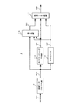
図1は、本発明の実施の形態1に係る画像処理装置である画像データ処理部3を備えた、画像表示装置の構成を示すブロック図である。図1に示されるように、画像表示装置は、受信部2と、画像データ処理部3と、表示部11とを主要な構成としている。なお、本出願において「…部」として示される構成は、電気回路等を含むハードウェアによって実現されるもの、又は、ソフトウェアによって実現されるもの、又は、ソフトウェアとハードウェアの組み合わせによって実現されるもののいずれであってもよい。なお、画像データ処理部3は、本発明の画像処理方法を実施することができる装置である。また、図1に示される画像表示装置は、例えば、液晶テレビである。
FIG. 1 is a block diagram showing a configuration of an image display device including an image
受信部2は、テレビチューナ等から構成されており、入力端子1を介して入力される映像信号に対し、選局及び復調等の処理を行うことにより、1フレーム分の画像(現フレーム画像又は現画像)を表す現画像データDi1を生成して、画像データ処理部3に順次出力する。
The
図1に示されるように、画像データ処理部3は、本発明の実施の形態1に係る画像符号化装置である符号化部4と、遅延部5と、第1の復号化部6と、第2の復号化部7と、変化量算出部8と、1フレーム前画像算出部9と、画像データ補正部10とを有している。画像データ処理部3は、現画像データDi1を階調値の変化に基づいて補正し、補正画像データDj1を表示部11に出力する。
As shown in FIG. 1, the image
表示部11の表示パネルは、例えば、液晶パネルであり、画像の輝度又は濃度を表す画像データDj1に対応する電圧を液晶に印加することにより、液晶の各画素の光透過率を変化させることによって、画像を表示する。
The display panel of the
次に、画像データ処理部3の動作を説明する。符号化部4は、現画像データDi1を符号化することによりデータ量を圧縮し、符号化画像データDa1を生成する。符号化部4による符号化方式としては、例えば、FBTC(Fixed Block Truncation Coding)又はGBTC(Generalized Block Truncation Coding)などのブロック符号化(BTC)を用いることができる。また、符号化部4における符号化方式として、JPEGに代表される2次元離散コサイン変換符号化、JPEG−LSに代表される予測符号化、JPEG2000に代表されるウェーブレット変換を用いた符号化方式を採用することができる。また、静止画用の符号化方式であれば任意の符号化方式を採用することができる。なお、採用する静止画用の符号化方式は、符号化前の画像データと復号化後の画像データとが完全に一致しない非可逆符号化であってもよい。ここで、符号化部4は、後述するように、各ブロックのダイナミックレンジの大きさに応じて符号化画像データ中の量子化画像データの数を決定し、すなわち、各ブロックの画素数を減少させる値を示す減少画素数を決定し、画素数が減少した符号化画像データDa1を出力する。
Next, the operation of the image
遅延部5は、符号化部4で生成された符号化画像データDa1を1フレームに相当する期間遅延させることによって、1フレーム前の符号化画像データDa0を出力する。符号化部4における画像データDi1の符号化率(データ圧縮率)を高くするほど、符号化画像データDa1を遅延するために必要な遅延部5のメモリ(図示せず)の記憶容量を小さくすることができる。
The
第1の復号化部6は、符号化画像データDa1の量子化ビット数をブロック毎に判別して復号化することにより、現画像データDi1に対応する復号化画像データDb1を出力する。また、第2の復号化部7は、遅延部5により1フレームに相当する期間遅延された符号化画像データDa0の量子化ビット数をブロック毎に判別して復号化することにより、1フレーム前の画像を表す復号化画像データDb0を出力する。
The
変化量算出部8は、現画像に対応する第1の復号化画像データDb1及び1フレーム前の画像に対応する第2の復号化画像データDb0に基づいて、第2の復号化画像データDb0から第1の復号化画像データDb1を減算することにより、1フレーム前の画像から現画像への画素毎の階調値の変化量Dv1を算出する。この変化量Dv1と、現画像データDi1は、1フレーム前画像算出部9に入力される。
Based on the first decoded image data Db1 corresponding to the current image and the second decoded image data Db0 corresponding to the image one frame before, the change
1フレーム前画像演算部9は、変化量算出部8により出力される階調値の変化量Dv1を現画像データDi1に加算することにより、1フレーム前画像データDp0を生成する。生成された1フレーム前画像データDp0は、画像データ補正部10に入力される。
The previous-frame
画像データ補正部10は、現画像データDi1と、1フレーム前画像データDp0との比較により得られる1フレーム間における階調値の変化に基づいて、液晶が1フレーム期間内に画像データDi1により指定される所定の透過率となるよう画像データDi1を補正し、補正画像データDj1を出力する。
The image
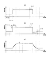
図2(a)〜(c)は、補正後画像データDj1に基づく駆動電圧を液晶に印加した場合の応答特性を示す図である。図2(a)は現画像データDi1の階調値(輝度値)の時間変化を示し、図2(b)は補正後画像データDj1の階調値(輝度値)の時間変化を示す。また、図2(c)において、実線は補正後画像データDj1に基づく駆動電圧を印加して得られる液晶パネルの表示輝度の時間変化(すなわち、液晶パネルの応答特性)を示し、破線は、補正後画像データDj1に基づく駆動電圧(図2(b)に示されるVH又はVL)を印加し続けた場合における液晶パネルの応答特性を示す。図2(b)に示されるように、階調値が増加又は減少する場合、補正量V1又はV2を現画像データDi1に加算又は減算することにより、補正後画像データDj1が生成される。この補正後画像データDj1に基づく駆動電圧を液晶に印加することにより、図2(c)に実線で示すように、略1フレーム期間内に液晶を現画像データDi1の階調値に対応する所定の透過率に到達させることができる。 2A to 2C are diagrams showing response characteristics when a driving voltage based on the corrected image data Dj1 is applied to the liquid crystal. 2A shows the time change of the gradation value (luminance value) of the current image data Di1, and FIG. 2B shows the time change of the gradation value (luminance value) of the corrected image data Dj1. In FIG. 2C, the solid line indicates the time change of the display luminance of the liquid crystal panel (that is, the response characteristic of the liquid crystal panel) obtained by applying the drive voltage based on the corrected image data Dj1, and the broken line is the correction. The response characteristics of the liquid crystal panel when the drive voltage based on the post-image data Dj1 (VH or VL shown in FIG. 2B) is continuously applied are shown. As shown in FIG. 2B, when the gradation value increases or decreases, the corrected image data Dj1 is generated by adding or subtracting the correction amount V1 or V2 to the current image data Di1. By applying a driving voltage based on the corrected image data Dj1 to the liquid crystal, as shown by a solid line in FIG. 2C, the liquid crystal is set within a predetermined period corresponding to the gradation value of the current image data Di1 within approximately one frame period. Can be reached.
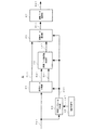
次に、実施の形態1に係る画像符号化装置である符号化部4の構成及び動作を説明する。図3は、符号化部4の構成を概略的に示すブロック図である。図3に示されるように、符号化部4は、画像データブロック化部12と、ダイナミックレンジ生成部13と、平均値生成部14と、量子化部15と、符号データ合成部16とを主要な構成としている。画像データブロック化部12は、現画像データDi1を所定の画素数毎にブロック分割することによってブロック画像データDc1を生成する。ダイナミックレンジ生成部13は、画像データブロック化部12から出力された各ブロック画像データDc1のダイナミックレンジを求め、ダイナミックレンジデータDd1を出力する。平均値生成部14は、画像データブロック化部12から出力された各ブロック画像データDc1の平均値を求め、平均値データDe1を算出する。量子化部15は、画像データブロック化部12から出力されたブロック画像データDc1の各画素データを量子化し、量子化画像データDf1を出力する。符号データ合成部16は、ダイナミックレンジデータDd1、平均値データDe1、及び量子化画像データDf1をビット結合して、符号化画像データDa1として出力する。
Next, the configuration and operation of the
図4は、量子化部15の構成を概略的に示すブロック図である。図4に示されるように、量子化部15は、閾値生成部17と、符号化パラメータ生成部18と、量子化閾値生成部19と、画素数減少部20と、画像データ量子化部21とを主要な構成としている。
FIG. 4 is a block diagram schematically showing the configuration of the
閾値生成部17は、ブロック画像データDc1の量子化ビット数をダイナミックレンジデータDd1の大きさに応じて切り替える際に用いられる切り替え閾値ta1を出力する。切り替え閾値ta1は、例えば、画像処理装置の製造段階で設定される値である。 The threshold generation unit 17 outputs a switching threshold ta1 used when switching the quantization bit number of the block image data Dc1 according to the size of the dynamic range data Dd1. The switching threshold ta1 is a value set at the manufacturing stage of the image processing apparatus, for example.
符号化パラメータ生成部18は、ダイナミックレンジデータDd1と切り替え閾値ta1との比較結果に基づいて、ブロック画像データDc1の量子化ビット数を決定する。また、符号化パラメータ生成部18は、ダイナミックレンジデータDd1と切り替え閾値ta1との比較結果に基づいて、ブロック画像データDc1の減少画素数を決定する。符号化パラメータ生成部18は、決定された量子化ビット数及び減少画素数を指定する符号化パラメータpa1を出力する。 The encoding parameter generation unit 18 determines the number of quantization bits of the block image data Dc1 based on the comparison result between the dynamic range data Dd1 and the switching threshold ta1. Also, the encoding parameter generation unit 18 determines the number of reduced pixels of the block image data Dc1 based on the comparison result between the dynamic range data Dd1 and the switching threshold ta1. The encoding parameter generation unit 18 outputs an encoding parameter pa1 that specifies the determined number of quantization bits and the number of reduced pixels.
量子化閾値生成部19は、ダイナミックレンジデータDd1、平均値データDe1、及び符号化パラメータpa1により指定される量子化ビット数に基づいて、ブロック画像データDc1を量子化する際に用いる量子化閾値tb1を算出する。量子化閾値tb1は、量子化ビット数から1を減じた数の閾値データから構成される。
The quantization
画素数減少部20は、符号化パラメータpa1により指定される減少画素数に基づいて、ブロック画像データDc1の画素数を減少させ、ブロック画像データDc1の画素数以下の画素で構成される画素数減少ブロック画像データDc1´を出力する。画素数減少部20において画素数を減少する方法としては、単純な画素間引きによる方法、又は、近傍画素同士の平均値を出力する方法など、画素数を減少できれる方法であれば種々の方法が採用できる。
The pixel
画像データ量子化部21は、画素数減少ブロック画像データDc1´の各画素データを量子化閾値tb1に含まれる閾値データによって量子化し、量子化画像データDf1として出力する。
The image
符号化パラメータpa1は、ブロック画像データDc1のダイナミックレンジデータDd1が小さい場合には画素数を減少することによる誤差の影響が小さいので、大きな減少画素数を指定する。また、符号化パラメータpa1は、ブロック画像データDc1のダイナミックレンジデータDd1が大きい場合には画素数を減少することによる誤差の影響が大きくなるので、小さな減少画素数を指定する。このように、ダイナミックレンジに応じてブロック画像データDc1の減少画素数を調節するので、符号化誤差を最小限に抑えつつ、符号化画像データDa1を小さくすることができる。 The encoding parameter pa1 designates a large reduction pixel number because the influence of an error due to the reduction of the pixel number is small when the dynamic range data Dd1 of the block image data Dc1 is small. In addition, when the dynamic range data Dd1 of the block image data Dc1 is large, the encoding parameter pa1 is more affected by an error due to a decrease in the number of pixels, and therefore, a small decrease pixel number is designated. Thus, since the number of reduced pixels of the block image data Dc1 is adjusted according to the dynamic range, the encoded image data Da1 can be reduced while minimizing the encoding error.
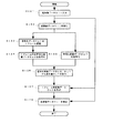
図5は、符号化部4における符号化処理の工程を示すフローチャートである。まず、現画像データDi1が画像データブロック化部12に入力されると(ステップSt1)、画像データブロック化部12は、現画像データDi1をブロックに分割し、ブロック画像データDc1を出力する(ステップSt2)。次に、ダイナミックレンジ生成部13は、ブロック画像データDc1のダイナミックレンジを検出してダイナミックレンジデータDd1を生成し(ステップSt3)、平均値生成部14は、ブロック画像データDc1の平均値を算出して平均値データDe1を生成する(ステップSt4)。符号化パラメータ生成部18は、ダイナミックレンジデータDd1と切り替え閾値ta1との比較結果に基づいて量子化ビット数を決定し、ダイナミックレンジデータDd1に基づいて減少画素数を決定し、決定された量子化ビット数及び減少画素数を指定する符号化パラメータpa1を出力する(ステップSt5)。次に、量子化閾値生成部19は、符号化パラメータpa1により指定される量子化ビット数に対応する量子化閾値tb1を算出する(ステップSt6)。画素数減少部20は、符号化パラメータpa1により指定される減少画素数に基づいて、ブロック画像データDc1の画素数を減少し、ブロック画像データDc1の画素数以下の画素で構成される画素数減少ブロック画像データDc1´を出力する(ステップSt7)。次に、画像データ量子化部21は、画素数減少ブロック画像データDc1´の各画素データを量子化閾値tb1に基づいて量子化し、量子化画像データDf1を出力する(ステップSt8)。符号データ合成部18は、ダイナミックレンジデータDd1、平均値データDe1、及び量子化画像データDf1をビット結合することにより、符号化画像データDa1を出力する(ステップSt9)。
FIG. 5 is a flowchart showing the steps of the encoding process in the
次に、第1の復号化部6及び第2の復号化部7の構成及び動作を説明する。図6は、第1の復号化部6の構成(第2の復号化部7と同じ構成)を示すブロック図である。図6に示されるように、第1の復号化部6は、閾値生成部22と、符号化パラメータ判別部23と、符号データ分割部24と、画像データ復元値生成部25と、画像データ復元部26と、画像データ補間部27とを主要な構成としている。
Next, the configuration and operation of the
閾値生成部22は、符号化パラメータの切り替え閾値ta1と同じ値に設定される判別閾値tc1を出力する。
The
符号化パラメータ判別部23は、符号化データDa1に含まれるダイナミックレンジデータDd1の値を判別閾値tc1と比較し、符号化画像データDa1の符号化パラメータPa1を判別し、判別されたパラメータを符号化パラメータpb1として出力する。
The encoding
符号データ分割部24は、符号化パラメータpb1を参照して、符号化画像データDa1をダイナミックレンジデータDd1、平均値データDe1、及び量子化画像データDf1に分割して出力する。
The code
画素データ復元値生成部25は、符号化パラメータpb1に基づいて、ダイナミックレンジデータDd1及び平均値データDe1から、復元値データra1を生成して出力する。この復元値データra1は、量子化画像データの各量子化値に対応する復元値から構成されるデータであり、この復元値は量子化ビット数分存在する。
The pixel data restoration
画素データ復元部26は、復元値データra1に基づいて量子化画像データDf1を復元し、画素数減少復号化画像データDh1を出力する。
The pixel
画像データ補間部27は、ブロック画像データDc1の画素数以下の画素数で構成される画素数減少復号化画像データDh1を補間することによって、ブロック画像データDc1の画素数に等しい画素数で構成される復号化画像データDb1を出力する。
The image
図7は、第1の復号化部6及び第2の復号化部7における復号化処理の工程を示すフローチャートである。まず、符号化画像データDa1が符号化パラメータ判別部23及び符号データ分割部24に入力されると(ステップSt11)、符号化パラメータ判別部23は、符号化データDa1に含まれるダイナミックレンジデータDd1と切り替え閾値ta1とを比較して符号化パラメータpb1を判別する(ステップSt12)。次に、符号データ分割部24は、符号化パラメータpb1を参照して、符号化画像データDa1をダイナミックレンジデータDd1、平均値データDe1、及び量子化画像データDf1に分割する(ステップSt13)。次に、画像データ復元値生成部25は、ダイナミックレンジデータDd1及び平均値データDe1から復元値データra1を生成する(ステップSt14)。次に、画像データ復元部26は、量子化画像データDf1を復元値データra1に基づいて復元し、画素数減少復号化画像データDh1を出力する(ステップSt15)。次に、画像データ補間部27は、ブロック画像データDc1の画素数よりも少ない画素数で構成される画素数減少復号化画像データDh1を補間することによって、ブロック画像データDc1に等しい画素数で構成される復号化画像データDb1を出力する(ステップSt16)。
FIG. 7 is a flowchart showing steps of the decoding process in the
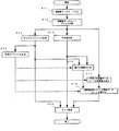
図8は、実施の形態1に係る画像処理装置である画像データ処理部3の処理工程を示すフローチャートである。まず、現画像データDi1が画像データ処理部3に入力されると(ステップSt21)、符号化部4は、現画像データDi1を図5に示す工程により符号化し、符号化画像データDa1を出力する(ステップSt22)。遅延部5は、符号化画像データDa1を1フレーム期間遅延し、1フレーム前の符号化画像データDa0を出力し(ステップSt23)、第2の復号化部7は、1フレーム前の符号化画像データDa0を図7に示す工程により復号化し、1フレーム前の現画像データDi0に対応する復号化画像データDb0を出力する(ステップSt24)。ステップSt23及びSt24の処理と並行して、第1の復号化部6は、符号化画像データDa1を図7に示す工程により復号化し、現フレームの現画像データDi1に対応する復号化画像データDb1を出力する(ステップSt25)。
FIG. 8 is a flowchart showing processing steps of the image
次に、変化量算出部8は、復号化画像データDb0から復号化画像データDb1を減算することにより、1フレーム前の画像から現画像への画素毎の階調値の変化を求め、この差分を変化量Dv1として出力する(ステップSt26)。次に、1フレーム前画像データ演算部9は、現画像データDi1に変化量Dv1を加算し、1フレーム前画像データDp0として出力する(ステップSt27)。次に、画像データ補正部10は、1フレーム前画像データDp0と、現画像データDi1との比較によって得られる階調値の変化に基づいて、液晶が1フレーム期間内に現画像データDi1により指定される所定の透過率となるよう駆動するのに必要な補正量を求め、この補正量を用いて現画像データDi1を補正し、補正画像データDj1(図2(b))を出力する(ステップSt28)。なお、上記ステップSt21〜St28の処理が、現画像データDi1の各画素に対して実施される。
Next, the change
以上に説明したように、実施の形態1に係る画像処理装置によれば、現画像データDi1を符号化する際、ブロック分割された画像データのダイナミックレンジが大きいほど減少画素数を小さくし、ダイナミックレンジが小さいほど減少画素数を大きくする。このように制御することで、符号化部4において発生する符号化誤差を最小限に抑えつつ、遅延部5のフレームメモリに一時的に記憶される画像データの量をより削減することができるので、遅延部5のフレームメモリの容量をより小さくすることが可能になる。
As described above, according to the image processing apparatus according to the first embodiment, when the current image data Di1 is encoded, the number of reduced pixels is reduced as the dynamic range of the block-divided image data is increased. The smaller the range, the larger the number of reduced pixels. By controlling in this way, it is possible to further reduce the amount of image data temporarily stored in the frame memory of the
なお、上記説明では、画像データ補正部10は1フレーム前画像データDp0と現画像データDi1との比較により得られる階調値の変化に基づいて補正量を算出し、補正画像データDj1を生成するものとしたが、ルックアップテーブル等のメモリ部に補正量を格納し、当該補正量を読み出して現画像データDi1を補正する構成としてもよい。
In the above description, the image
図9は、画像データ補正部10の構成の一例を示すブロック図である。図9に示す画像データ補正部10は、ルックアップテーブル(LUT)28、及び補正部29により構成される。ルックアップテーブル28は、1フレーム前画像データDp0と現画像データDi1を入力とし、両者の値に基づいて補正量Dg1を出力する。
FIG. 9 is a block diagram illustrating an example of the configuration of the image
図10は、図9に示されるルックアップテーブル28の構成の一例を示す模式図である。ルックアップテーブル28には、現画像データDi1及び1フレーム前画像データDp0が読み出しアドレスとして入力される。現画像データDi1及び1フレーム前画像データDp0がそれぞれ8ビットの画像データの場合、ルックアップテーブル28には256×256個のデータが補正量Dg1として格納される。ルックアップテーブル28は、現画像データDi1、及び1フレーム前画像データDp0の各値に対応する補正量Dg1=dt(Di1,Dp0)を読み出して出力する。補正部29は、ルックアップテーブル28により出力された補正量Dg1を現画像データDi1に加算し、補正画像データDj1を出力する。
FIG. 10 is a schematic diagram showing an example of the configuration of the lookup table 28 shown in FIG. The look-up table 28 receives the current image data Di1 and the previous frame image data Dp0 as read addresses. When the current image data Di1 and the previous frame image data Dp0 are 8-bit image data, 256 × 256 pieces of data are stored in the lookup table 28 as the correction amount Dg1. The look-up table 28 reads out and outputs correction amounts Dg1 = dt (Di1, Dp0) corresponding to the values of the current image data Di1 and the previous frame image data Dp0. The
図11は、液晶の応答時間の一例を示す図である。図11において、x軸は現画像データDi1の値(現画像における階調値)、y軸は1フレーム前の現画像データDi0の値(1フレーム前の画像における階調値)であり、z軸は液晶が1フレーム前の階調値に対応する透過率から現画像データDi1の階調値に対応する透過率となるまでに要する応答時間を示している。ここで、現画像の階調値が8ビットの場合、現画像データ及び1フレーム前の画像データの階調値の組合せは256×256通り存在するので、応答時間も256×256通り存在する。図11においては、階調値の組合せに対応する応答時間を8×8通りに簡略化して示している。 FIG. 11 is a diagram illustrating an example of the response time of the liquid crystal. In FIG. 11, the x-axis is the value of the current image data Di1 (gradation value in the current image), the y-axis is the value of the current image data Di0 one frame before (the gradation value in the image one frame before), and z The axis indicates the response time required for the liquid crystal to reach the transmittance corresponding to the gradation value of the current image data Di1 from the transmittance corresponding to the gradation value of the previous frame. Here, when the gradation value of the current image is 8 bits, there are 256 × 256 combinations of the gradation values of the current image data and the image data of the previous frame, and there are 256 × 256 response times. In FIG. 11, response times corresponding to combinations of gradation values are simplified and shown in 8 × 8 ways.
図12は、液晶が1フレーム期間経過時に現画像データDi1により指定される透過率となるよう現画像データDi1に加算される補正量Dg1の値を示す図である。現画像データの階調値が8ビットの場合、補正画像データDj1は、現画像データ及び1フレーム前の画像データの階調値の組合せに対応して256×256通り存在する。図12においては、図11と同様に階調値の組合せに対応する補正量を8×8通りに簡略化して示している。 FIG. 12 is a diagram showing the value of the correction amount Dg1 added to the current image data Di1 so that the liquid crystal has the transmittance specified by the current image data Di1 when one frame period elapses. When the gradation value of the current image data is 8 bits, there are 256 × 256 correction image data Dj1 corresponding to combinations of the gradation values of the current image data and the image data one frame before. In FIG. 12, similarly to FIG. 11, correction amounts corresponding to combinations of gradation values are simplified and shown in 8 × 8 ways.
図11に示されるように、液晶の応答時間は、現画像データ及び1フレーム前の画像データの階調値に応じて異なるため、ルックアップテーブル28には、現画像データ及び1フレーム前の画像データの両階調値に対応する256×256通りの補正量Dg1が格納される。液晶は特に、中間階調(グレー)における応答速度が遅い。従って、中間階調を表す1フレーム前画像データDp0と、高階調を表す現画像データDi1に対応する補正量Dg1=dt(Di1,Dp0)の値を大きく設定することにより、応答速度を効果的に向上させることができる。また、液晶の応答特性は液晶の材料、電極形状、温度などによって変化するので、こうした使用条件に対応する補正量Dg1をルックアップテーブル28に格納することにより、液晶の特性に応じて応答時間を制御することができる。 As shown in FIG. 11, since the response time of the liquid crystal varies depending on the gradation values of the current image data and the image data of the previous frame, the lookup table 28 includes the current image data and the image of the previous frame. 256 × 256 correction amounts Dg1 corresponding to both gradation values of the data are stored. In particular, the liquid crystal has a slow response speed in the middle gradation (gray). Therefore, the response speed can be effectively increased by setting a large value of the correction amount Dg1 = dt (Di1, Dp0) corresponding to the image data Dp0 one frame before representing the intermediate gradation and the current image data Di1 representing the high gradation. Can be improved. Further, since the response characteristics of the liquid crystal change depending on the material of the liquid crystal, the electrode shape, the temperature, and the like, the correction amount Dg1 corresponding to such use conditions is stored in the lookup table 28, so that the response time can be set according to the characteristics of the liquid crystal. Can be controlled.
以上のように、予め求められた補正量Dg1を格納したルックアップテーブル28を用いることにより、補正画像データDj1を出力する際の演算量を削減することができる。 As described above, by using the lookup table 28 that stores the correction amount Dg1 obtained in advance, the amount of calculation when the corrected image data Dj1 is output can be reduced.
図13は、実施の形態1に係る画像データ補正部10の他の構成を示すブロック図である。図13に示すルックアップテーブル(LUT)30は、1フレーム前画像データDp0、及び現画像データDi1を入力とし、両者の値に基づいて補正画像データDj1=(Di1,Dp0)を出力する。ルックアップテーブル30には、図12に示す補正量Dg1=(Di1,Dp0)を、現画像データDi1に加算することにより得られる256×256通りの補正画像データDj1=(Di1,Dp0)が格納される。なお、補正画像データDj1は、表示部11の表示可能な階調の範囲を超えないよう設定される。
FIG. 13 is a block diagram illustrating another configuration of the image
図14は、ルックアップテーブル30に格納される補正画像データDj1の一例を示す図である。現画像データの階調値が8ビットの場合、補正画像データDj1は、現画像データ及び1フレーム前の画像データの階調値の組合せに対応して256×256通り存在する。図14においては階調値の組合せに対応する補正量を8×8通りに簡略化して示している。 FIG. 14 is a diagram illustrating an example of the corrected image data Dj1 stored in the lookup table 30. When the gradation value of the current image data is 8 bits, there are 256 × 256 correction image data Dj1 corresponding to combinations of the gradation values of the current image data and the image data one frame before. In FIG. 14, the correction amount corresponding to the combination of gradation values is simplified and shown in 8 × 8 ways.
このように、予め求められた補正画像データDj1をルックアップテーブル30に格納し、現画像データDi1及び1フレーム前画像データDp0に基づいて対応する補正画像データDj1を出力することにより、補正画像データDj1をそれぞれ出力する際の演算量をさらに削減することができる。 Thus, the corrected image data Dj1 obtained in advance is stored in the lookup table 30, and the corresponding corrected image data Dj1 is output based on the current image data Di1 and the one-frame previous image data Dp0, thereby correcting the corrected image data. The amount of calculation when outputting Dj1 can be further reduced.
実施の形態2.
図15は、本発明の実施の形態2に係る画像処理装置である画像データ処理部40を備えた、画像表示装置の構成を示すブロック図である。図15において、図1に示される構成と同一又は対応する構成には、同じ符号を付す。実施の形態2に係る画像データ処理部40は、符号化部4の前段に色空間変換部41を備え、第1の復号化部6の後段に色空間変換部42を備え、第2の復号化部7の後段に色空間変換部43を備えている点が、上記実施の形態1に係る画像データ処理部3と相違する。
FIG. 15 is a block diagram illustrating a configuration of an image display apparatus including an image
色空間変換部41は、現画像データDi1を輝度信号Y及び色信号Cb,Crからなる画像データに変換し、変換された現画像データDt1を出力する。符号化部4は、現画像データDt1を符号化し、現画像データDt1に対応する符号化画像データDa1を出力する。遅延部5は、符号化画像データDa1を1フレームに相当する期間遅延することにより、現画像の1フレーム前の画像に対応する符号化画像データDa0を出力する。第1の復号化部6及び第2の復号化部7は、符号化画像データDa1,Da0を復号化することにより、現画像に対応する復号化画像データDb1,Db0を出力する。
The color space conversion unit 41 converts the current image data Di1 into image data composed of the luminance signal Y and the color signals Cb and Cr, and outputs the converted current image data Dt1. The
色空間変換部42及び43は、輝度信号及び色信号からなる復号化画像データDb1,Db0をRGBのデジタル信号に変換し、変換された画像データDu1,Du0を出力する。 The color space conversion units 42 and 43 convert the decoded image data Db1 and Db0 composed of the luminance signal and the color signal into RGB digital signals, and output the converted image data Du1 and Du0.
変化量算出部8は、1フレーム前の画像データに対応する復号化画像データDu0から現フレームの画像データに対応する復号化画像データDu1を減算することにより、1フレーム前の画像から現画像への画素毎の階調値の変化量Dv1を算出する。この変化量Dv1は、現画像データDi1とともに1フレーム前画像演算部9に入力される。
The change
1フレーム前画像演算部9は、変化量算出部8により出力される階調値の変化量Dv1を現画像データDi1に加算することにより、1フレーム前画像データDp0を生成する。生成された1フレーム前画像データDp0は、画像データ補正部10に入力される。
The previous-frame
画像データ補正部10は、現画像データDi1と、1フレーム前画像データDp0との比較により得られる1フレーム間における階調値の変化に基づいて、液晶が1フレーム期間内に画像データDi1により指定される所定の透過率となるよう画像データDi1を補正し、補正画像データDj1を出力する。
The image
実施の形態2に係る符号化部4は、実施の形態1と同様に、現画像データDt1をブロック分割したブロック画像データDc1を生成し、分割された各ブロックごとにブロック画像データDc1を用いてダイナミックレンジデータDd1と平均値データDe1とブロック画像データDc1を量子化した量子化画像データDf1を生成する。この際、ブロック画像データDc1、ダイナミックレンジデータDd1、平均値データDe1、及び量子化画像データDf1は、輝度信号Y及び色信号Cb,Crのそれぞれについて生成される。
Similar to the first embodiment, the
図16(a),(b1),(b2),(c1),(c2)は、実施の形態2に係る符号化画像データのデータ構成の一例を示す図である。図16(a),(b1),(b2),(c1),(c2)は、実施の形態2におけるダイナミックレンジデータDd1、平均値データDe1、及び量子化画像データDf1の一例を示しており、1ブロックあたりの輝度信号Y及び色信号Cb,Crに含まれる画素数をそれぞれ8個とした場合を示している。なお、図中それぞれ四角の中に記載している数字は各データのビット数である。
16 (a), (b1), (b2), (c1), and (c2) are diagrams illustrating an example of a data configuration of encoded image data according to
図16(a)は、輝度信号Y及び色信号Cb,Crのブロック画像データDc1を示しており、1ブロック内に8ビットの画像データが8画素あることを示している。 FIG. 16A shows block image data Dc1 of the luminance signal Y and the color signals Cb and Cr, and shows that there are 8 pixels of 8-bit image data in one block.
図16(b1)は、輝度信号Y及び色信号Cb,Crのブロック画像データDc1の減少画素数が4画素である場合の画素数減少ブロック画像データDc1´を示している。図16(b2)は、輝度信号Yのブロック画像データDc1の減少画素数が0であり、色信号Cb,Crのブロック画像データDc1の減少画素数が6である場合の画素数減少ブロック画像データDc1´を示している。 FIG. 16B1 shows the pixel number reduced block image data Dc1 ′ when the number of reduced pixels of the block image data Dc1 of the luminance signal Y and the color signals Cb and Cr is four. FIG. 16B2 is a block image data in which the number of reduced pixels in the block image data Dc1 of the luminance signal Y is 0 and the number of reduced pixels in the block image data Dc1 of the color signals Cb and Cr is 6. Dc1 ′ is shown.
また、図16(c1)は、同図(b1)に示した画素数減少ブロック画像データDc1´を符号化することによって得られる符号化画像データDa1を示している。また、図16(c2)は、同図(b2)に示した画素数減少ブロック画像データDc1´を符号化することによって得られる符号化画像データDa1を示している。図16(c1)及び(c2)のそれぞれの符号化画像データは、ダイナミックレンジデータDd1、平均値データDe1、及び量子化画像データDf1によって構成されている。 FIG. 16C1 shows encoded image data Da1 obtained by encoding the pixel number reduced block image data Dc1 ′ shown in FIG. FIG. 16C2 shows encoded image data Da1 obtained by encoding the pixel number reduced block image data Dc1 ′ shown in FIG. Each of the encoded image data in (c1) and (c2) of FIG. 16 includes dynamic range data Dd1, average value data De1, and quantized image data Df1.
実施の形態2においては、1ブロック内のデータのダイナミックレンジが小さい場合には、画素数を減少することによって発生する誤差が小さいので、図16(b2)のように、色信号Cb,Crの減少画素数を大きし、輝度信号Yの減少画素数を小さくする。逆に、色信号CrとCrのダイナミックレンジが大きい場合には、図16(b1)のように、実施の形態2においては、輝度信号Yと色信号Cb、Crの減少画素数を同じ値に設定する。このように、色信号Cb、Crのダイナミックレンジに応じて輝度信号Yと色信号Cb、Crの減少画素数を調整することにより、符号化画像データDa1のデータ量を一定に保ちながら、画素数を減少することによる誤差の影響を最小限に抑えることが可能である。 In the second embodiment, when the dynamic range of the data in one block is small, an error caused by reducing the number of pixels is small. Therefore, as shown in FIG. The reduced pixel number is increased and the decreased pixel number of the luminance signal Y is decreased. Conversely, when the dynamic range of the color signals Cr and Cr is large, as shown in FIG. 16 (b1), in the second embodiment, the number of reduced pixels of the luminance signal Y and the color signals Cb and Cr are set to the same value. Set. As described above, the number of pixels is maintained while keeping the data amount of the encoded image data Da1 constant by adjusting the number of reduced pixels of the luminance signal Y and the color signals Cb and Cr according to the dynamic range of the color signals Cb and Cr. It is possible to minimize the influence of errors due to the reduction of.
なお、画素数減少部20における、画素数を減少するための方法としては、単純な画素間引きや、近傍画素同士の平均値を出力するなど、画素数を減少できればどのような方法を用いてもよい。
In addition, as a method for reducing the number of pixels in the pixel
図17(a),(b1),(b2),(c1),(c2)は、実施の形態2に係る符号化画像データのデータ構成の他の例を示す図である。図17(a),(b1),(b2),(c1),(c2)は、実施の形態2におけるダイナミックレンジデータDd1、平均値データDe1、及び量子化画像データDf1の他の例を示す図であり、1ブロックあたりの輝度信号Yに含まれる画素数を8個、色信号Cb,Crに含まれる画素数をそれぞれ16個とした場合を示している。なお、図中それぞれ四角の中に記載している数字は各データのビット数である。
17 (a), (b1), (b2), (c1), and (c2) are diagrams illustrating another example of the data configuration of the encoded image data according to
図17(a)は、ブロック画像データDc1を示しており、輝度信号Yは2ブロック分の画像データを、色信号Cb,Crは1ブロック分の画像データを示している。 FIG. 17A shows block image data Dc1, the luminance signal Y indicates image data for two blocks, and the color signals Cb and Cr indicate image data for one block.
図17(b1)は、輝度信号Yの減少画素数が4であり、色信号Cb,Crの減少画素数が12である場合の画素数減少ブロック画像データDc1´を示している。また、図17(b2)は、輝度信号Yの減少画素数が0であり、色信号Cb,Crの減少画素数が16である場合の画素数減少ブロック画像データDc1´を示している。 FIG. 17B1 shows the pixel number reduced block image data Dc1 ′ when the number of reduced pixels of the luminance signal Y is 4 and the number of reduced pixels of the color signals Cb and Cr is 12. FIG. 17 (b2) shows the pixel number reduced block image data Dc1 ′ when the number of reduced pixels of the luminance signal Y is 0 and the number of reduced pixels of the color signals Cb and Cr is 16.
また、図17(c1)は、同図(b1)に示した画素数減少ブロック画像データDc1´を符号化することによって得られる符号化画像データDa1を示している。図17(c2)は、同図(b2)に示した画素数減少ブロック画像データDc1´を符号化することによって得られる符号化画像データDa1を示している。図17(c1)及び(c2)のそれぞれの符号化画像データは、ダイナミックレンジデータDd1、平均値データDe1、及び量子化画像データDf1によって構成されている。 FIG. 17C1 shows encoded image data Da1 obtained by encoding the pixel number reduced block image data Dc1 ′ shown in FIG. FIG. 17C2 shows encoded image data Da1 obtained by encoding the pixel number reduced block image data Dc1 ′ shown in FIG. Each of the encoded image data in (c1) and (c2) of FIG. 17 includes dynamic range data Dd1, average value data De1, and quantized image data Df1.
図17(a),(b1),(b2),(c1),(c2)に示される例の場合、輝度信号Yと色信号Cb,Crの1ブロックに含まれる画素数が異なり、輝度信号Yの2ブロック分の画素数が色信号Cb,Crの1ブロック分の画素数に等しい。 17 (a), (b1), (b2), (c1), and (c2), the number of pixels included in one block of the luminance signal Y and the color signals Cb and Cr is different. The number of pixels for two blocks of Y is equal to the number of pixels for one block of color signals Cb and Cr.
1ブロック内のデータのダイナミックレンジが小さい場合には、画素数を減少することによって発生する誤差が小さいので、図17の例においては、画素数減少部20は、色信号CbとCrのダイナミックレンジが共に小さい場合には、図17(b2)のように、色信号Cb、Crの画素数が0になるまで減少画素数を大きして、輝度信号Yの減少画素数を0にする。
When the dynamic range of the data in one block is small, an error generated by reducing the number of pixels is small. Therefore, in the example of FIG. 17, the pixel
逆に、色信号CbとCrいずれかのダイナミックレンジが大きい場合には、図17(b1)のように、輝度信号Yの減少画素数を4に設定し、色信号Cb、Crの減少画素数を12に設定する。このように、図16の例のように輝度信号Yと色信号Cb,Crの1対のブロック画像データだけで減少画素数の調節を行うのではなく、複数のブロック間で減少画素数を調節することも可能であり、符号化画像データDa1のデータ量が一定になるような減少画素数の組合せであれば用いることができる。 Conversely, when the dynamic range of either the color signal Cb or Cr is large, as shown in FIG. 17 (b1), the reduced pixel number of the luminance signal Y is set to 4, and the reduced pixel number of the color signals Cb and Cr. Is set to 12. As described above, the number of reduced pixels is adjusted between a plurality of blocks instead of adjusting the number of reduced pixels only with a pair of block image data of the luminance signal Y and the color signals Cb and Cr as in the example of FIG. It is also possible to use a combination of reduced pixels so that the amount of encoded image data Da1 is constant.
また、図17の例のように、減少画素数を1ブロックに含まれる画素数と等しくすることで、画素数減少ブロック画像データDc1´の画素数を0にし、符号化画像データDa1をダイナミックレンジデータDd1と平均値データDe1のみで構成することもできる。 Further, as shown in the example of FIG. 17, by making the reduced pixel number equal to the pixel number included in one block, the pixel number of the pixel number reduced block image data Dc1 ′ is set to 0, and the encoded image data Da1 is changed to the dynamic range. It can also be configured only by the data Dd1 and the average value data De1.
以上に説明した実施の形態2に係る画像処理装置によれば、色信号Cb,Crのダイナミックレンジが小さい場合には、色信号Cb,Crの減少画素数を大きくすると同時に輝度信号Yの減少画素数を小さくするように制御するので、画素数を減少することによる符号化誤差を低減するとともに符号化画像データ量を一定に保つことが可能である。 According to the image processing apparatus according to the second embodiment described above, when the dynamic range of the color signals Cb and Cr is small, the number of reduced pixels of the color signals Cb and Cr is increased and at the same time the decreased pixels of the luminance signal Y. Since the number is controlled to be small, it is possible to reduce the coding error due to the reduction in the number of pixels and to keep the amount of coded image data constant.
また、色信号Cb,Crのダイナミックレンジが小さい場合には、色信号Cb,Crの減少画素数を大きくすると同時に輝度信号Yの減少画素数を小さくするように制御することによって、画素数を減少した場合の符号化誤差を低減するので、圧縮率を高くした場合であっても誤差の小さい補正画像データDj1を生成することが可能である。すなわち、画像データを符号化により削減した場合であっても、符号化誤差による不要な過電圧を印加することなく液晶の応答速度を適切に制御することができるので、符号化画像データDa1を遅延するために必要な遅延部5のフレームメモリの容量を少なくすることが可能である。
In addition, when the dynamic range of the color signals Cb and Cr is small, the number of pixels is reduced by increasing the number of reduced pixels of the color signals Cb and Cr and simultaneously reducing the number of reduced pixels of the luminance signal Y. Since the encoding error in this case is reduced, it is possible to generate corrected image data Dj1 with a small error even when the compression rate is increased. That is, even when the image data is reduced by encoding, the response speed of the liquid crystal can be appropriately controlled without applying unnecessary overvoltage due to the encoding error, so that the encoded image data Da1 is delayed. Therefore, it is possible to reduce the capacity of the frame memory of the
実施の形態3.
図18は、本発明の実施の形態3に係る画像処理装置である画像データ処理部44を備えた、液晶表示装置の構成を示すブロック図である。図18において、図1に示される構成と同一又は対応する構成には、同じ符号を付す。実施の形態3の画像データ処理部44が、図1に示される実施の形態1の画像データ処理部3と異なる点は、第1の復号化部6の後段に第1の高域成分強調部45を備え、第2の復号化部7の後段に第2の高域成分強調部46を備え、第1の復号化部6から第1の高域成分強調部45に復号化画像データDb1と符号化パラメータPb1が出力され、第2の復号化部7から第2の高域成分強調部46に復号化画像データDb0と符号化パラメータPb0が出力され、変化量算出部8は第1の高域成分強調部45からの出力Db1aと第2の高域成分強調部46からの出力Db0aとの差分を計算する点である。
FIG. 18 is a block diagram illustrating a configuration of a liquid crystal display device including an image
図19は、第1の高域成分強調部45(又は第2の高域成分強調部46)の内部構成を示すブロック図である。実施の形態3において、第1の高域成分強調部45と第2の高域成分強調部46とは、同じ構成及び機能を持つ。図19に示されるように、第1の高域成分強調部45(又は第2の高域成分強調部46)は、高周波成分検出部47と、強調量生成部48と、強調量加算部49とを有している。
FIG. 19 is a block diagram showing an internal configuration of the first high frequency component emphasizing unit 45 (or the second high frequency component emphasizing unit 46). In the third embodiment, the first high frequency
高周波成分検出部47は、バンドパスフィルタ(BPF)等を有し、第1の復号化画像データDb1(又は第2の復号化画像データDb0)に含まれる高周波成分を抽出し、高周波成分信号R1(又はR0)を出力する。 The high frequency component detection unit 47 includes a band pass filter (BPF) and the like, extracts a high frequency component contained in the first decoded image data Db1 (or the second decoded image data Db0), and outputs a high frequency component signal R1. (Or R0) is output.
強調量生成部48は、高周波成分信号R1(又はR0)、予め定められたゲイン量G、及び第1の復号化部6(又は第2の復号化部7)から出力された符号化パラメータPb1(又はPb0)に基づいて、強調量信号SH1(又はSH0)を出力する。図20は、強調量生成部48の内部構成を示すブロック図である。図20に示されるように、強調量生成部48は、高周波成分信号R1(又はR0)に予め定められたゲイン量Gを積算して高周波成分信号R1G(又はR0G)を出力する積算器50と、この積算器50から出力される高周波成分信号R1G(又はR0G)と、符号化パラメータPb1(又はPb0)とが入力される画素数減少判定部51とを有する。画素数減少判定部51は、符号化パラメータPb1(又はPb0)により、符号化部4で画像データの画素数が減少されているか否かを判定し、画素数が減少されていると判定したときは、強調量信号SH1(又はSH0)として、高周波成分信号R1G(又はR0G)を反転させ、任意のゲイン係数を積算した信号を出力する。また、画素数減少判定部51は、画素数が減少されていないと判定したときは、強調量信号SH1(又はSH0)として0を出力する。
The enhancement amount generation unit 48 includes the high-frequency component signal R1 (or R0), a predetermined gain amount G, and the encoding parameter Pb1 output from the first decoding unit 6 (or the second decoding unit 7). Based on (or Pb0), the enhancement amount signal SH1 (or SH0) is output. FIG. 20 is a block diagram illustrating an internal configuration of the enhancement amount generation unit 48. As shown in FIG. 20, the enhancement amount generator 48 integrates a predetermined gain amount G with the high frequency component signal R1 (or R0) and outputs a high frequency component signal R1G (or R0G). The high frequency component signal R1G (or R0G) output from the
強調量加算部49は、第1の復号化画像データDb1(又は第2の復号化画像データDb0)に、強調量生成部48から出力された強調量信号SH1(又はSH0)を加算し、高域強調された第1の復号化画像データDb1a(又は高域強調された第2の復号化画像データDb0a)を出力する。なお、図18に示される構成の内の上記以外の構成は、上記実施の形態1において説明した構成と同様の構成及び機能を持つ。
The enhancement
次に、図18に示される画像データ処理部44の動作について説明する。図21(a)及び(b)は、画像データ処理部44における復号化後のデータを示す図であり、同図(a)は符号化部4にて画素数を減少させない場合を示し、同図(b)は符号化部4にて画素数を減少させた場合を示している。図21(a)及び(b)において、縦軸はある画素の輝度値、横軸は時間である。図21(a)及び(b)においては、画像が1フレーム期間に1画素ずつ移動している場合を示している。画素数を減少させる方法には、画素を間引くことによって画素数を減少させる方法と、近接する複数の画素の平均化処理によって得られたデータを持つ画素に置き換えることによって画素数を減少させる方法とがある。図21(b)は、平均化処理を行うことによって画素数を減少させる方法を用いた場合を示しており、平均化処理によって、元々急峻な輝度変化(図21(a)に示されるような輝度変化)であったエッジ部分に、新たに中間調の画素が生成される場合を示している。この中間調を有する補完されたエッジが動くとき、ある画素をフレーム間で比較すると、図21(b)に示すような変化が観測される。
Next, the operation of the image
図22(a)及び(b)は、実施の形態3の第1の高域成分強調部45及び第2の高域成分強調部46の高域強調機能を動作させない場合に生じことがある問題点を説明するための図である。図22(a)及び(b)は、画像データ処理部44から出力される補正画像データDj1を示し、同図(a)は符号化部4にて画素数を減少させない場合を示し、同図(b)は符号化部4にて画素数を減少させた場合を示している。図22(a)及び(b)はそれぞれ、図21(a)及び(b)に対応している。図22(a)は、図21(a)において連続する2フレーム間を比較して、前フレームよりも輝度値が増加しているときには、その増加量に応じた値だけ輝度値を増加させ、前フレームよりも輝度値が減少しているときには、その減少量に応じた値だけ輝度値を減少させることによって得られる。図22(b)は、図21(b)において連続する2フレーム間を比較して、前フレームよりも輝度値が増加しているときには、その増加量に応じた値だけ輝度値を増加させ、前フレームよりも輝度値が減少しているときには、その減少量に応じた値だけ輝度値を減少させることによって得られる。図22(a)に示されるように、符号化部4にて画素数を減少させないときには、補正画像データに付加される補正量V1,V2の振幅は大きいが、図22(b)に示されるように、符号化部4にて画素数を減少させたときには、補正量V1a,V2aの振幅が小さくなり、また、輝度値が長い時間をかけて変化する(すなわち、図22(b)における輝度値の変化が幅広になる)ため、画素数を減少させた場合のみ液晶応答速度の改善効果が減少してしまう可能性がある。
22 (a) and 22 (b) may occur when the high frequency emphasis function of the first high frequency
図23(a)〜(d)は、第1の高域成分強調部45及び第2の高域成分強調部46の動作を示す図である。ここでは、説明を簡単にするため、図21(b)に示す復号化画像データDb1(又はDb0)を1フレーム毎に1画素ずつ移動している場合を例として用い、その信号の画素ごとの変化を図23(a)に示す。また、図23(b)は、図23(a)に示される復号化画像データDb1に対して、高周波成分検出部47において、任意のバンドパスフィルタ(BPF)による処理(2次微分処理)を施した後の出力信号である高周波成分信号R1(又はR0)を示す図である。Y(n)をn画素位置の輝度値とすると、BPF出力は、例えば、
2Y(n)−{Y(n−1)+Y(n+1)}
によって得られる。
FIGS. 23A to 23D are diagrams illustrating operations of the first high frequency
2Y (n)-{Y (n-1) + Y (n + 1)}
Obtained by.
図23(c)は、図23(b)を反転させ、係数を掛けることによって得られる。図23(d)は高周波成分信号R1(又はR0)を、強調量生成部48において符号反転することで生成した、強調量信号SH1(又はSH0)を、強調量加算部49において、第1の復号化画像データDb1(又は第2の復号化画像データDb0)に加算することによって生成した第1の復号化信号Db1a(又は第2の復号化信号Db0a)を示している。
FIG. 23C is obtained by inverting FIG. 23B and multiplying by a coefficient. FIG. 23D shows the enhancement amount signal SH1 (or SH0) generated by inverting the sign of the high frequency component signal R1 (or R0) in the enhancement amount generation unit 48, and the enhancement
図24(a)及び(b)は、実施の形態3の第1の高域成分強調部45及び第2の高域成分強調部46の高域強調機能を動作させた場合の画像データ処理部44から出力される補正画像データDj1を示し、同図(a)は符号化部4にて画素数を減少させない場合を示し、同図(b)は符号化部4にて画素数を減少させた場合を示している。図24(a)及び(b)はそれぞれ、図21(a)及び図23(d)に対応している。図24(a)は、図21(a)において連続する2フレーム間を比較して、前フレームよりも輝度値が増加しているときには、その増加量に応じた値だけ輝度値を増加させ、前フレームよりも輝度値が減少しているときには、その減少量に応じた値だけ輝度値を減少させることによって得られる。図24(b)は、図23(d)において連続する2フレーム間を比較して、前フレームよりも輝度値が増加しているときには、その増加量に応じた値だけ輝度値を増加させ、前フレームよりも輝度値が減少しているときには、その減少量に応じた値だけ輝度値を減少させることによって得られる。図24(b)に示されるように、符号化部4にて画素数を減少させたときであっても、補正量V1b,V2bの振幅は大きくなるので、画素数を減少させた場合であっても、十分な液晶応答速度の改善効果を得ることが可能となる。
24A and 24B show an image data processing unit when the high-frequency emphasis function of the first high-frequency
また画素位置によって画素数の減少数が異なる場合、全ての画面領域において高周波成分強調処理を行うと、信号や画素位置によって生成される補正量に差が出てしまい、画面のちらつき等の画質劣化に繋がる可能性がある。しかし、実施の形態3に示す画像処理装置においては、第1の復号化部6(又は第2の復号化部7)から出力される符号化データPb1(又はPb0)を基に、画素数減少判定部51にて、強調量信号SH1(又はSH0)を制御する。よって、画素数を削減している場合は高周波成分を強調し、画素数を削減していない場合は復号化画像データDb1(又はDb0)をそのままDb1a(又はDb0a)として出力することで、信号によって、また画素位置によって画素数の減少数が異なる場合においても、画面全体に均一な補正量を生成することが可能となる。
In addition, when the number of pixels decreases depending on the pixel position, if high-frequency component enhancement processing is performed in all screen areas, there will be a difference in the amount of correction generated depending on the signal and pixel position, resulting in image quality degradation such as screen flickering. May lead to However, in the image processing apparatus shown in the third embodiment, the number of pixels is decreased based on the encoded data Pb1 (or Pb0) output from the first decoding unit 6 (or the second decoding unit 7). The
以上に説明した実施の形態3に係る画像処理装置によれば、画像数を減少させた後に符号化処理を行った場合に低下する高周波数成分を、復号化後に強調するので、画素数を減少させることで圧縮率を高くした場合であっても、高周波数領域の信号に対しても誤差の少ない補正画像データDj1を生成することが可能である。すなわち、画素数を減少させた場合であっても、画像の高周波数領域に対して十分に過電圧を印加することが可能になる。 According to the image processing apparatus according to the third embodiment described above, the high frequency components that decrease when the encoding process is performed after reducing the number of images are emphasized after decoding, so the number of pixels is reduced. Thus, even when the compression rate is increased, it is possible to generate the corrected image data Dj1 with little error even for a signal in a high frequency region. That is, even when the number of pixels is reduced, a sufficient overvoltage can be applied to the high frequency region of the image.
なお、以上に説明した内容は、図25に示すように、画像データ処理部52が、符号化部4の前段の色空間変換部41と、第1及び第2の高域成分強調部45,46の後段の色空間変換部42,43とを備えた場合にも適用可能である。なお、図25において、図15に示される構成と同一又は対応する構成には、同じ符号を付す。実施の形態3に係る画像データ処理部40は、上記実施の形態2に示すように、輝度信号及び色差信号ごとに画素数減少数が異なる場合に有効である。
Note that the content described above is that, as shown in FIG. 25, the image
1 入力端子、 2 受信部、 3 画像データ処理部(画像処理装置)、 4 符号化部(画像符号化装置)、 5 遅延部、 6 第1の復号化部、 7 第2の復号化部、 8 変化量算出部、 9 1フレーム前画像演算部、 10 画像データ補正部、 11 表示部、 12 画像データブロック化部、 13 ダイナミックレンジ生成部、 14 平均値生成部、 15 量子化部、 16 符号データ合成部、 17 閾値生成部、 18 符号化パラメータ生成部、 19 量子化閾値生成部、 20 画素数減少部、 21 画像データ量子化部、 22 閾値生成部、 23 符号化パラメータ判別部、 24 符号データ分割部、 25 画像データ復元値生成部、 26 画像データ復元部、 27 画像データ補間部、 28 ルックアップテーブル、 29 補正部、 30 ルックアップテーブル、 40 画像データ処理部、 41,42,43 色空間変換部、 44 画像データ処理部、 45 第1の高周波成分強調部、 46 第2の高周波成分強調部、 47 高周波成分検出部、 48 強調量生成部、 49 強調量加算部、 50 積算器、 51 画素数減少判定部、 52 画像データ処理部。
1 input terminal, 2 receiving unit, 3 image data processing unit (image processing device), 4 encoding unit (image encoding device), 5 delay unit, 6 first decoding unit, 7 second decoding unit, 8 change amount calculation unit, 9 1 frame previous image calculation unit, 10 image data correction unit, 11 display unit, 12 image data block formation unit, 13 dynamic range generation unit, 14 average value generation unit, 15 quantization unit, 16 code Data synthesis unit, 17 threshold generation unit, 18 encoding parameter generation unit, 19 quantization threshold generation unit, 20 pixel number reduction unit, 21 image data quantization unit, 22 threshold generation unit, 23 encoding parameter determination unit, 24 code Data division unit, 25 image data restoration value generation unit, 26 image data restoration unit, 27 image data interpolation unit, 28 lookup table, 29 correction unit, 30 lookup table 40, image data processing unit, 41, 42, 43 color space conversion unit, 44 image data processing unit, 45 first high frequency component enhancement unit, 46 second high frequency component enhancement unit, 47 high frequency component detection unit, 48 enhancement An amount generation unit, 49 an enhancement amount addition unit, 50 an integrator, 51 a pixel number decrease determination unit, and 52 an image data processing unit.
Claims (14)
入力する画像データを複数のブロックに分割して得られたブロック画像データを出力する画像データブロック化部と、
前記ブロック画像データのダイナミックレンジを求め、前記ダイナミックレンジを示すダイナミックレンジデータを出力するダイナミックレンジ生成部と、
前記ブロック画像データの平均値を求め、前記平均値を示す平均値データを出力する平均値生成部と、
減少画素数が入力され、前記ブロック画像データの画素数を前記減少画素数減らすことによって画素数減少ブロック画像データを生成する画素数減少部と、
前記画像データの量子化ビット数を、前記ダイナミックレンジデータの大きさに応じて切換え、前記色信号のダイナミックレンジがあらかじめ設定された値よりも小さい場合、前記色信号の減少画素数を大きくしてデータ圧縮率を高め、かつ前記輝度信号の減少画素数を小さくしてデータ圧縮率を低くするように決定し、前記量子化ビット数と前記減少画素数を指定する符号化パラメータを生成する符号化パラメータ生成部と、
前記ダイナミックレンジデータ、前記平均値データ、及び前記量子化ビット数によって決まるダイナミックレンジ内のある値を量子化閾値とする量子化閾値生成部と、
前記量子化閾値を用いて前記画素数減少ブロック画像データを量子化することによって量子化画像データを生成する画像データ量子化部と
を有し、
前記ダイナミックレンジ生成部で求められた、入力する色信号のダイナミックレンジデータに基づき、前記画素数減少部における、前記輝度信号の減少画素数と前記色信号の減少画素数を制御する
ことを特徴とする画像符号化装置。 In an image encoding device that quantizes image data composed of luminance signals and color signals,
An image data blocking unit that outputs block image data obtained by dividing input image data into a plurality of blocks;
Obtaining a dynamic range of the block image data, and outputting a dynamic range data indicating the dynamic range;
An average value generating unit for obtaining an average value of the block image data and outputting average value data indicating the average value;
A pixel number reduction unit that receives a reduced pixel number and generates the pixel number reduced block image data by reducing the pixel number of the block image data by reducing the reduced pixel number;
The quantization bit number of the image data is switched according to the size of the dynamic range data, and when the dynamic range of the color signal is smaller than a preset value, the number of reduced pixels of the color signal is increased. Encoding to increase the data compression rate and to determine a reduction in the data compression rate by reducing the number of reduced pixels of the luminance signal, and to generate an encoding parameter specifying the quantization bit number and the reduced pixel number A parameter generator;
A quantization threshold generation unit that sets a certain value within a dynamic range determined by the dynamic range data, the average value data, and the number of quantization bits as a quantization threshold;
An image data quantization unit that generates quantized image data by quantizing the pixel number reduced block image data using the quantization threshold;
Based on the dynamic range data of the input color signal obtained by the dynamic range generation unit, the number of pixels of the luminance signal and the number of pixels of the color signal are controlled in the pixel number reduction unit. An image encoding device.
前記符号化画像データを復号化することにより前記現フレームの画像データに対応する第1の復号化画像データを出力する第1の復号化部と、
前記符号化画像データを1フレームに相当する期間遅延させる遅延部と、
前記遅延部から出力される前記符号化画像データを、前記色信号のダイナミックレンジデータに基づき復号化することにより、前記現フレームの1フレーム前の画像データに対応する第2の復号化画像データを出力する第2の復号化部と、
前記第2の復号化画像データから前記第1の復号化画像データを減算することにより算出される変化量を画素毎に求める変化量算出部と、
前記第2の復号化画像データから前記第1の復号化画像データを減算することにより算出される変化量と、前記現フレームの画像データとを加算することで、前記1フレーム前の画像データに対応する再生画像データを算出する1フレーム前画像演算部と、
前記現フレームの画像データ及び前記再生画像データとの比較により得られる階調値の変化に基づいて、前記現フレームの画像の階調値を補正する画像データ補正部と
を有することを特徴とする画像処理装置。 An encoding unit that has the same configuration as the image encoding device according to claim 2 and encodes image data of an input current frame and outputs encoded image data;
A first decoding unit that outputs first decoded image data corresponding to the image data of the current frame by decoding the encoded image data;
A delay unit that delays the encoded image data for a period corresponding to one frame;
By decoding the encoded image data output from the delay unit based on the dynamic range data of the color signal, second decoded image data corresponding to image data one frame before the current frame is obtained. A second decoding unit to output;
A change amount calculation unit for obtaining a change amount calculated for each pixel by subtracting the first decoded image data from the second decoded image data ;
The change amount calculated by subtracting the first decoded image data from the second decoded image data and the image data of the current frame are added to the image data of the previous frame. One frame previous image calculation unit for calculating corresponding reproduction image data;
An image data correction unit that corrects a gradation value of the image of the current frame based on a change in a gradation value obtained by comparing the image data of the current frame and the reproduced image data. Image processing device.
現フレームの画像データを複数のブロックに分割して得られたブロック画像データを出力し、
前記ブロック画像データのダイナミックレンジを求め、前記ダイナミックレンジを示すダイナミックレンジデータを出力し、
前記ブロック画像データの平均値を求め、前記平均値を示す平均値データを出力し、
前記画像データの量子化ビット数を、前記ダイナミックレンジデータの大きさに応じて切換え、前記色信号のダイナミックレンジがあらかじめ設定された値よりも小さい場合、前記色信号の減少画素数を大きくしてデータ圧縮率を高め、かつ前記輝度信号の減少画素数を小さくしてデータ圧縮率を低くするように決定し、前記量子化ビット数と前記減少画素数を指定する符号化パラメータを生成し、
前記ダイナミックレンジデータ、前記平均値データ、及び前記量子化ビット数によって決まるダイナミックレンジ内のある値である量子化閾値を生成し、
前記量子化閾値を用いて前記画素数減少ブロック画像データを量子化することによって量子化画像データを生成し、
入力する色信号の前記ダイナミックレンジデータに基づき、前記輝度信号の減少画素数と前記色信号の減少画素数を制御する
ことを特徴とすることを特徴とする画像符号化方法。 In an image encoding method for quantizing image data composed of a luminance signal and a color signal,
Output the block image data obtained by dividing the image data of the current frame into a plurality of blocks,
Obtain the dynamic range of the block image data, output the dynamic range data indicating the dynamic range,
Obtain an average value of the block image data, and output average value data indicating the average value,
The quantization bit number of the image data is switched according to the size of the dynamic range data, and when the dynamic range of the color signal is smaller than a preset value, the number of reduced pixels of the color signal is increased. Determining the data compression rate to be increased and reducing the number of reduced pixels of the luminance signal to reduce the data compression rate, and generating the encoding parameters specifying the quantization bit number and the reduced pixel number;
Generating a quantization threshold that is a value within a dynamic range determined by the dynamic range data, the average value data, and the number of quantization bits;
Generating quantized image data by quantizing the pixel number reduced block image data using the quantization threshold;
An image coding method characterized by controlling the number of reduced pixels of the luminance signal and the number of reduced pixels of the color signal based on the dynamic range data of the input color signal.
前記符号化画像データを復号化することにより前記現フレームの画像データに対応する第1の復号化画像データを出力し、
前記符号化画像データを1フレームに相当する期間遅延させ、
遅延した前記符号化画像データを前記色信号のダイナミックレンジデータに基づき復号化することにより、前記現フレームの1フレーム前の画像データに対応する第2の復号化画像データを出力し、
前記第2の復号化画像データから前記第1の復号化画像データを減算することにより算出される変化量を画素毎に求め、
前記第2の復号化画像データから前記第1の復号化画像データを減算することにより算出される間の変化量と、前記現フレームの画像データとを加算することで得られる、前記1フレーム前の画像データに対応する再生画像データと、前記現フレームの画像データとの比較により得られる階調値の変化に基づいて、前記現フレームの画像の階調値を補正する
ことを特徴とする画像処理方法。 According to the image encoding method of claim 8 , the input current frame image data is encoded and encoded image data is output,
Decoding the encoded image data to output first decoded image data corresponding to the image data of the current frame;
The encoded image data is delayed for a period corresponding to one frame,
By decoding the delayed encoded image data based on the dynamic range data of the color signal, the second decoded image data corresponding to the image data one frame before the current frame is output,
Obtaining a change amount calculated for each pixel by subtracting the first decoded image data from the second decoded image data ;
The previous frame obtained by adding the amount of change calculated by subtracting the first decoded image data from the second decoded image data and the image data of the current frame. And correcting the gradation value of the image of the current frame based on a change in gradation value obtained by comparing the reproduced image data corresponding to the image data of the current frame and the image data of the current frame. Processing method.
前記第2の復号化画像データの高周波成分を強調して第2の高周波成分強調済み復号化画像データとする高周波成分強調部と、
前記第2の高周波成分強調済み復号化画像データから前記第1の高周波成分強調済み復号化画像データを減算することにより算出される変化量を画素毎に求める変化量算出部と、
前記変化量と前記現フレームの画像データとを用いて、前記1フレーム前の画像データに対応する再生画像データを算出する1フレーム前画像演算部と、
前記現フレームの画像データおよび前記再生画像データに基づいて、前記現フレームの画像の階調値を補正する補正部とを備え、
前記符号化部は、現フレームの画像データの各ブロックにおける画像データの前記輝度信号の画素数と前記色信号の画素数を減少する画素数減少部を備え、
前記現フレームの画像データの各ブロックにおける前記色信号のダイナミックレンジに基づいて、各ブロックにおける前記現フレームの画像データの前記輝度信号の減少画素数と前記色信号の減少画素数を調整する
ことを特徴とする請求項3乃至5のいずれかに記載の画像処理装置。 A high-frequency component emphasizing unit that emphasizes the high-frequency component of the first decoded image data and sets the first high-frequency component-enhanced decoded image data;
A high-frequency component emphasizing unit that emphasizes the high-frequency component of the second decoded image data to obtain the second high-frequency component-enhanced decoded image data;
A change amount calculation unit for obtaining a change amount calculated for each pixel by subtracting the first high frequency component emphasized decoded image data from the second high frequency component emphasized decoded image data ;
A one-frame-previous image calculation unit that calculates reproduction image data corresponding to the image data of the previous frame by using the amount of change and the image data of the current frame;
A correction unit that corrects a gradation value of the image of the current frame based on the image data of the current frame and the reproduced image data;
The encoding unit includes a pixel number reduction unit that reduces the number of pixels of the luminance signal and the number of pixels of the color signal of the image data in each block of the image data of the current frame,
Adjusting the number of reduced pixels of the luminance signal and the number of reduced pixels of the color signal in the image data of the current frame in each block based on the dynamic range of the color signal in each block of the image data of the current frame. the image processing apparatus according to any one of claims 3 to 5, characterized.
前記第1の復号化画像データの高周波成分を強調して第1の高周波成分強調済み復号化画像データとする工程と、
前記第2の復号化画像データの高周波成分を強調して第2の高周波成分強調済み復号化画像データとする工程と、
前記第2の高周波成分強調済み復号化画像データから前記第1の高周波成分強調済み復号化画像データを減算することにより算出される変化量を画素毎に求める工程と、
前記変化量と前記現フレームの画像データとを用いて、前記1フレーム前の画像データに対応する再生画像データを算出する工程と、
前記現フレームの画像データ及び前記再生画像データに基づいて、前記現フレームの画像の階調値を補正する工程と、
現フレームの画像データの各ブロックにおける画像データの前記輝度信号の画素数と前記色信号の画素数を減少する工程とを備え、
前記現フレームの画像データの各ブロックにおける前記色信号のダイナミックレンジに基づいて、各ブロックにおける前記現フレームの画像データの前記輝度信号の減少画素数と前記色信号の減少画素数を調整する
ことを特徴とする請求項9又は10のいずれかに記載の画像処理方法。 Outputting the second decoded image data corresponding to the image data one frame before the current frame by decoding the encoded image data output by the delay means;
Emphasizing high-frequency components of the first decoded image data to obtain first high-frequency component-enhanced decoded image data;
Emphasizing the high frequency component of the second decoded image data to obtain second high frequency component enhanced decoded image data;
Obtaining a change amount calculated for each pixel by subtracting the first high frequency component enhanced decoded image data from the second high frequency component enhanced decoded image data ;
Using the change amount and the image data of the current frame to calculate reproduction image data corresponding to the image data of the previous frame;
Correcting a gradation value of the image of the current frame based on the image data of the current frame and the reproduced image data;
Reducing the number of pixels of the luminance signal of the image data and the number of pixels of the color signal in each block of the image data of the current frame,
Adjusting the number of reduced pixels of the luminance signal and the number of reduced pixels of the color signal in the image data of the current frame in each block based on the dynamic range of the color signal in each block of the image data of the current frame. the image processing method according to any one of claims 9 or 10, characterized.
前記復号化画像データの高周波成分を検出する高周波成分検出部と、
前記高周波成分検出部の検出結果を基に、前記復号化画像データに加算される高周波成分強調量を算出する強調量生成部とを有し、
前記強調量生成部は、前記符号化部において前記画像データの減少画素数を調整した結果に基づき、画素が減少させられている場合に前記高周波成分強調量を出力する
ことを特徴とする請求項11記載の画像処理装置。 The high-frequency component emphasis unit is
A high-frequency component detector that detects a high-frequency component of the decoded image data;
Based on the detection result of the high-frequency component detection unit, an enhancement amount generation unit that calculates a high-frequency component enhancement amount added to the decoded image data,
The enhancement amount generation unit outputs the high-frequency component enhancement amount when the number of pixels is reduced based on a result of adjusting the number of pixels to be reduced in the image data in the encoding unit.
The image processing apparatus according to claim 11 .
前記復号化画像データの高周波成分を検出する高周波成分検出工程と、
前記高周波成分検出工程の検出結果を基に、前記復号化画像データに加算される高周波成分強調量を算出する強調量生成工程とを有し、
前記強調量生成工程においては、前記符号化方法において前記画像データの減少画素数を調整した結果に基づき、画素が減少させられている場合に前記高周波成分強調量を出力する
ことを特徴とする請求項12記載の画像処理方法。 The step of enhancing the high-frequency component of the decoded image data includes:
A high frequency component detection step of detecting a high frequency component of the decoded image data;
An enhancement amount generating step for calculating a high frequency component enhancement amount to be added to the decoded image data based on the detection result of the high frequency component detection step;
In the enhancement amount generation step, the high-frequency component enhancement amount is output when the number of pixels is reduced based on the result of adjusting the number of reduction pixels of the image data in the encoding method.
The image processing method according to claim 12 .
Priority Applications (5)
| Application Number | Priority Date | Filing Date | Title |
|---|---|---|---|
| JP2006192546A JP4169768B2 (en) | 2006-02-24 | 2006-07-13 | Image coding apparatus, image processing apparatus, image coding method, and image processing method |
| KR20077029751A KR20080026112A (en) | 2006-02-24 | 2006-10-18 | Image encoding device, image processing device, image display device, image encoding method, and image processing method |
| US11/918,128 US8237689B2 (en) | 2006-02-24 | 2006-10-18 | Image encoding device, image processing device, image display device, image encoding method, and image processing method |
| PCT/JP2006/320741 WO2007097067A1 (en) | 2006-02-24 | 2006-10-18 | Image encoding device, image processing device, image display device, image encoding method, and image processing method |
| TW095144117A TWI349255B (en) | 2006-02-24 | 2006-11-29 | Image encoding apparatus, image processing apparatus, image display apparatus嚗mage encoding method, and image processing method |
Applications Claiming Priority (2)
| Application Number | Priority Date | Filing Date | Title |
|---|---|---|---|
| JP2006048180 | 2006-02-24 | ||
| JP2006192546A JP4169768B2 (en) | 2006-02-24 | 2006-07-13 | Image coding apparatus, image processing apparatus, image coding method, and image processing method |
Publications (2)
| Publication Number | Publication Date |
|---|---|
| JP2007259405A JP2007259405A (en) | 2007-10-04 |
| JP4169768B2 true JP4169768B2 (en) | 2008-10-22 |
Family
ID=38437123
Family Applications (1)
| Application Number | Title | Priority Date | Filing Date |
|---|---|---|---|
| JP2006192546A Expired - Fee Related JP4169768B2 (en) | 2006-02-24 | 2006-07-13 | Image coding apparatus, image processing apparatus, image coding method, and image processing method |
Country Status (5)
| Country | Link |
|---|---|
| US (1) | US8237689B2 (en) |
| JP (1) | JP4169768B2 (en) |
| KR (1) | KR20080026112A (en) |
| TW (1) | TWI349255B (en) |
| WO (1) | WO2007097067A1 (en) |
Families Citing this family (17)
| Publication number | Priority date | Publication date | Assignee | Title |
|---|---|---|---|---|
| JP4169768B2 (en) | 2006-02-24 | 2008-10-22 | 三菱電機株式会社 | Image coding apparatus, image processing apparatus, image coding method, and image processing method |
| US8675998B2 (en) * | 2007-12-06 | 2014-03-18 | Mitsubishi Electric Corporation | Method and apparatus for high frequency component smoothing, and image display apparatus |
| US8325268B2 (en) * | 2007-12-28 | 2012-12-04 | Sanyo Electric Co., Ltd. | Image processing apparatus and photographing apparatus |
| US8270773B2 (en) | 2008-08-04 | 2012-09-18 | Kabushiki Kaisha Toshiba | Image processing apparatus and image processing method |
| JP2012134848A (en) * | 2010-12-22 | 2012-07-12 | Sony Corp | Signal processor and signal processing method |
| EP2774371B1 (en) * | 2011-11-03 | 2020-08-26 | Sun Patent Trust | Efficient rounding for deblocking |
| EP2603000B1 (en) * | 2011-12-08 | 2017-11-01 | Dolby Laboratories Licensing Corporation | Guided prediction-filtering in layered vdr image coding |
| JP6099884B2 (en) | 2012-05-25 | 2017-03-22 | 三菱電機株式会社 | Stereoscopic image display device |
| KR20140037309A (en) * | 2012-09-13 | 2014-03-27 | 삼성전자주식회사 | Image compression circuit and display system having the same |
| KR101995866B1 (en) * | 2013-02-05 | 2019-07-04 | 삼성전자주식회사 | Display apparatus and control method thereof |
| KR102201108B1 (en) * | 2014-01-20 | 2021-01-11 | 삼성디스플레이 주식회사 | Display device and driving method thereof |
| US9734603B2 (en) * | 2015-06-30 | 2017-08-15 | General Electric Company | Systems and methods for peak tracking and gain adjustment |
| GB2542125A (en) * | 2015-09-08 | 2017-03-15 | Sony Corp | Colour conversion |
| CN107293262B (en) * | 2016-03-31 | 2019-10-18 | 上海和辉光电有限公司 | For driving control method, control device and the display device of display screen |
| WO2018064274A1 (en) * | 2016-09-30 | 2018-04-05 | General Electric Company | Systems and methods for spectral analysis and gain adjustment |
| JP6672363B2 (en) * | 2018-03-23 | 2020-03-25 | シャープ株式会社 | Encoding device, display device, encoding device control method, and control program |
| KR102618692B1 (en) | 2018-06-15 | 2024-01-02 | 삼성전자주식회사 | Display driver circuit and method for reducing influence of noise or dither |
Family Cites Families (24)
| Publication number | Priority date | Publication date | Assignee | Title |
|---|---|---|---|---|
| JPH0821865B2 (en) * | 1986-05-14 | 1996-03-04 | ソニー株式会社 | High efficiency encoder |
| JPH0821864B2 (en) * | 1986-05-14 | 1996-03-04 | ソニー株式会社 | High efficiency encoder |
| JP2841362B2 (en) * | 1987-12-25 | 1998-12-24 | 松下電器産業株式会社 | High efficiency coding device |
| US5166987A (en) * | 1990-04-04 | 1992-11-24 | Sony Corporation | Encoding apparatus with two stages of data compression |
| JP3117091B2 (en) * | 1990-08-23 | 2000-12-11 | 富士ゼロックス株式会社 | Image coding device |
| JP2969867B2 (en) * | 1990-08-31 | 1999-11-02 | ソニー株式会社 | High-efficiency encoder for digital image signals. |
| US5414527A (en) | 1991-08-14 | 1995-05-09 | Fuji Xerox Co., Ltd. | Image encoding apparatus sensitive to tone variations |
| US5440344A (en) * | 1992-04-28 | 1995-08-08 | Mitsubishi Denki Kabushiki Kaisha | Video encoder using adjacent pixel difference for quantizer control |
| JP3221120B2 (en) * | 1992-12-25 | 2001-10-22 | ソニー株式会社 | Decryption device |
| JP2616652B2 (en) * | 1993-02-25 | 1997-06-04 | カシオ計算機株式会社 | Liquid crystal driving method and liquid crystal display device |
| JPH07307869A (en) * | 1994-05-13 | 1995-11-21 | Fuji Xerox Co Ltd | Image processing unit |
| JPH09148938A (en) | 1995-11-21 | 1997-06-06 | Seiko Epson Corp | Method and device for data compression and expansion |
| JP3687080B2 (en) * | 1996-07-17 | 2005-08-24 | ソニー株式会社 | Image encoding device, image encoding method, image decoding device, image decoding method, and recording medium |
| JP3748088B2 (en) * | 1996-07-17 | 2006-02-22 | ソニー株式会社 | Image processing apparatus and method, and learning apparatus and method |
| US6381369B1 (en) * | 1996-07-17 | 2002-04-30 | Sony Corporation | Image coding apparatus, image coding method, image decoding method, image decoding apparatus, image data transmitting method and recording medium |
| US6898319B1 (en) * | 1998-09-11 | 2005-05-24 | Intel Corporation | Method and system for video frame enhancement using edge detection |
| JP3617498B2 (en) * | 2001-10-31 | 2005-02-02 | 三菱電機株式会社 | Image processing circuit for driving liquid crystal, liquid crystal display device using the same, and image processing method |
| JP3694004B2 (en) | 2002-06-14 | 2005-09-14 | 三菱電機株式会社 | Liquid crystal drive circuit, liquid crystal drive method, and liquid crystal display device |
| JP3673257B2 (en) * | 2002-06-14 | 2005-07-20 | 三菱電機株式会社 | Image data processing device, image data processing method, and liquid crystal display device |
| JP3703806B2 (en) | 2003-02-13 | 2005-10-05 | 三菱電機株式会社 | Image processing apparatus, image processing method, and image display apparatus |
| US8139090B2 (en) * | 2005-03-10 | 2012-03-20 | Mitsubishi Electric Corporation | Image processor, image processing method, and image display device |
| JP2007174634A (en) * | 2005-11-28 | 2007-07-05 | Victor Co Of Japan Ltd | Layered coding and decoding methods, apparatuses, and programs |
| JP4169768B2 (en) | 2006-02-24 | 2008-10-22 | 三菱電機株式会社 | Image coding apparatus, image processing apparatus, image coding method, and image processing method |
| JP4190551B2 (en) * | 2006-07-18 | 2008-12-03 | 三菱電機株式会社 | Image processing apparatus, image processing method, image encoding apparatus, and image encoding method |
-
2006
- 2006-07-13 JP JP2006192546A patent/JP4169768B2/en not_active Expired - Fee Related
- 2006-10-18 KR KR20077029751A patent/KR20080026112A/en active Search and Examination
- 2006-10-18 US US11/918,128 patent/US8237689B2/en not_active Expired - Fee Related
- 2006-10-18 WO PCT/JP2006/320741 patent/WO2007097067A1/en active Application Filing
- 2006-11-29 TW TW095144117A patent/TWI349255B/en not_active IP Right Cessation
Also Published As
| Publication number | Publication date |
|---|---|
| US8237689B2 (en) | 2012-08-07 |
| JP2007259405A (en) | 2007-10-04 |
| US20090085896A1 (en) | 2009-04-02 |
| KR20080026112A (en) | 2008-03-24 |
| TWI349255B (en) | 2011-09-21 |
| WO2007097067A1 (en) | 2007-08-30 |
| TW200733040A (en) | 2007-09-01 |
Similar Documents
| Publication | Publication Date | Title |
|---|---|---|
| JP4169768B2 (en) | Image coding apparatus, image processing apparatus, image coding method, and image processing method | |
| US7327340B2 (en) | Liquid-crystal driving circuit and method | |
| US8150203B2 (en) | Liquid-crystal-driving image processing circuit, liquid-crystal-driving image processing method, and liquid crystal display apparatus | |
| KR100539857B1 (en) | Image data processing method, and image data processing circuit | |
| US7034788B2 (en) | Image data processing device used for improving response speed of liquid crystal display panel | |
| JP4609457B2 (en) | Image processing apparatus and image processing method | |
| KR100886295B1 (en) | Image processing device, image processing method, and image display device | |
| US11388408B2 (en) | Interpolation of reshaping functions | |
| KR100917530B1 (en) | Image processing device, image processing method, image coding device, image coding method and image display device | |
| US7436382B2 (en) | Correction data output device, correction data correcting method, frame data correcting method, and frame data displaying method | |
| JP4144600B2 (en) | Image processing apparatus, image processing method, and image display apparatus | |
| US7925111B2 (en) | Image processing apparatus and method, and image coding apparatus and method | |
| JP3753731B1 (en) | Image processing apparatus, image processing method, and image display apparatus | |
| JP4100405B2 (en) | Image processing apparatus, image processing method, and image display apparatus | |
| JP2003345318A (en) | Circuit and method for driving liquid crystal and liquid crystal display device |
Legal Events
| Date | Code | Title | Description |
|---|---|---|---|
| A131 | Notification of reasons for refusal |
Free format text: JAPANESE INTERMEDIATE CODE: A131 Effective date: 20080311 |
|
| A521 | Written amendment |
Free format text: JAPANESE INTERMEDIATE CODE: A523 Effective date: 20080410 |
|
| TRDD | Decision of grant or rejection written | ||
| A01 | Written decision to grant a patent or to grant a registration (utility model) |
Free format text: JAPANESE INTERMEDIATE CODE: A01 Effective date: 20080805 |
|
| A01 | Written decision to grant a patent or to grant a registration (utility model) |
Free format text: JAPANESE INTERMEDIATE CODE: A01 |
|
| A61 | First payment of annual fees (during grant procedure) |
Free format text: JAPANESE INTERMEDIATE CODE: A61 Effective date: 20080805 |
|
| FPAY | Renewal fee payment (event date is renewal date of database) |
Free format text: PAYMENT UNTIL: 20110815 Year of fee payment: 3 |
|
| R150 | Certificate of patent or registration of utility model |
Ref document number: 4169768 Country of ref document: JP Free format text: JAPANESE INTERMEDIATE CODE: R150 Free format text: JAPANESE INTERMEDIATE CODE: R150 |
|
| FPAY | Renewal fee payment (event date is renewal date of database) |
Free format text: PAYMENT UNTIL: 20110815 Year of fee payment: 3 |
|
| FPAY | Renewal fee payment (event date is renewal date of database) |
Free format text: PAYMENT UNTIL: 20120815 Year of fee payment: 4 |
|
| FPAY | Renewal fee payment (event date is renewal date of database) |
Free format text: PAYMENT UNTIL: 20120815 Year of fee payment: 4 |
|
| FPAY | Renewal fee payment (event date is renewal date of database) |
Free format text: PAYMENT UNTIL: 20130815 Year of fee payment: 5 |
|
| R250 | Receipt of annual fees |
Free format text: JAPANESE INTERMEDIATE CODE: R250 |
|
| R250 | Receipt of annual fees |
Free format text: JAPANESE INTERMEDIATE CODE: R250 |
|
| R250 | Receipt of annual fees |
Free format text: JAPANESE INTERMEDIATE CODE: R250 |
|
| R250 | Receipt of annual fees |
Free format text: JAPANESE INTERMEDIATE CODE: R250 |
|
| LAPS | Cancellation because of no payment of annual fees |