JP4167932B2 - Resin floor panel structure - Google Patents
Resin floor panel structure Download PDFInfo
- Publication number
- JP4167932B2 JP4167932B2 JP2003120244A JP2003120244A JP4167932B2 JP 4167932 B2 JP4167932 B2 JP 4167932B2 JP 2003120244 A JP2003120244 A JP 2003120244A JP 2003120244 A JP2003120244 A JP 2003120244A JP 4167932 B2 JP4167932 B2 JP 4167932B2
- Authority
- JP
- Japan
- Prior art keywords
- floor panel
- trunk
- spare tire
- floor
- exposed
- Prior art date
- Legal status (The legal status is an assumption and is not a legal conclusion. Google has not performed a legal analysis and makes no representation as to the accuracy of the status listed.)
- Expired - Fee Related
Links
- 229920005989 resin Polymers 0.000 title claims description 30
- 239000011347 resin Substances 0.000 title claims description 30
- 239000006260 foam Substances 0.000 claims description 44
- 238000003860 storage Methods 0.000 claims description 41
- 230000002093 peripheral effect Effects 0.000 claims description 12
- 239000011324 bead Substances 0.000 claims description 7
- 239000000463 material Substances 0.000 description 19
- 239000011358 absorbing material Substances 0.000 description 14
- 230000000694 effects Effects 0.000 description 13
- 238000010521 absorption reaction Methods 0.000 description 6
- 238000000465 moulding Methods 0.000 description 6
- 238000000034 method Methods 0.000 description 5
- 238000005187 foaming Methods 0.000 description 4
- 239000012779 reinforcing material Substances 0.000 description 4
- 229920003002 synthetic resin Polymers 0.000 description 4
- 239000000057 synthetic resin Substances 0.000 description 4
- 239000013585 weight reducing agent Substances 0.000 description 4
- 229910000831 Steel Inorganic materials 0.000 description 3
- 239000011810 insulating material Substances 0.000 description 3
- 238000009413 insulation Methods 0.000 description 3
- 239000010959 steel Substances 0.000 description 3
- 229920002430 Fibre-reinforced plastic Polymers 0.000 description 2
- 239000004677 Nylon Substances 0.000 description 2
- 239000004743 Polypropylene Substances 0.000 description 2
- 238000010586 diagram Methods 0.000 description 2
- 239000011151 fibre-reinforced plastic Substances 0.000 description 2
- 239000004088 foaming agent Substances 0.000 description 2
- 238000004519 manufacturing process Methods 0.000 description 2
- 229920001778 nylon Polymers 0.000 description 2
- 229920001155 polypropylene Polymers 0.000 description 2
- 239000007787 solid Substances 0.000 description 2
- 229920000049 Carbon (fiber) Polymers 0.000 description 1
- JOYRKODLDBILNP-UHFFFAOYSA-N Ethyl urethane Chemical compound CCOC(N)=O JOYRKODLDBILNP-UHFFFAOYSA-N 0.000 description 1
- 239000004917 carbon fiber Substances 0.000 description 1
- 238000005520 cutting process Methods 0.000 description 1
- 239000000428 dust Substances 0.000 description 1
- 239000000835 fiber Substances 0.000 description 1
- 239000000446 fuel Substances 0.000 description 1
- 239000011521 glass Substances 0.000 description 1
- 239000003365 glass fiber Substances 0.000 description 1
- 238000002347 injection Methods 0.000 description 1
- 239000007924 injection Substances 0.000 description 1
- 239000004745 nonwoven fabric Substances 0.000 description 1
- -1 polypropylene Polymers 0.000 description 1
- 230000003014 reinforcing effect Effects 0.000 description 1
- 230000000630 rising effect Effects 0.000 description 1
- 238000007789 sealing Methods 0.000 description 1
- 239000000454 talc Substances 0.000 description 1
- 229910052623 talc Inorganic materials 0.000 description 1
- 239000011800 void material Substances 0.000 description 1
Images


Classifications
-
- B—PERFORMING OPERATIONS; TRANSPORTING
- B62—LAND VEHICLES FOR TRAVELLING OTHERWISE THAN ON RAILS
- B62D—MOTOR VEHICLES; TRAILERS
- B62D25/00—Superstructure or monocoque structure sub-units; Parts or details thereof not otherwise provided for
- B62D25/08—Front or rear portions
- B62D25/087—Luggage compartments
-
- B—PERFORMING OPERATIONS; TRANSPORTING
- B60—VEHICLES IN GENERAL
- B60R—VEHICLES, VEHICLE FITTINGS, OR VEHICLE PARTS, NOT OTHERWISE PROVIDED FOR
- B60R13/00—Elements for body-finishing, identifying, or decorating; Arrangements or adaptations for advertising purposes
- B60R13/01—Liners for load platforms or load compartments
- B60R13/011—Liners for load platforms or load compartments for internal load compartments, e.g. car trunks
-
- B—PERFORMING OPERATIONS; TRANSPORTING
- B60—VEHICLES IN GENERAL
- B60R—VEHICLES, VEHICLE FITTINGS, OR VEHICLE PARTS, NOT OTHERWISE PROVIDED FOR
- B60R5/00—Compartments within vehicle body primarily intended or sufficiently spacious for trunks, suit-cases, or the like
- B60R5/04—Compartments within vehicle body primarily intended or sufficiently spacious for trunks, suit-cases, or the like arranged at rear of vehicle
-
- B—PERFORMING OPERATIONS; TRANSPORTING
- B62—LAND VEHICLES FOR TRAVELLING OTHERWISE THAN ON RAILS
- B62D—MOTOR VEHICLES; TRAILERS
- B62D29/00—Superstructures, understructures, or sub-units thereof, characterised by the material thereof
- B62D29/04—Superstructures, understructures, or sub-units thereof, characterised by the material thereof predominantly of synthetic material
- B62D29/041—Understructures
-
- B—PERFORMING OPERATIONS; TRANSPORTING
- B62—LAND VEHICLES FOR TRAVELLING OTHERWISE THAN ON RAILS
- B62D—MOTOR VEHICLES; TRAILERS
- B62D43/00—Spare wheel stowing, holding, or mounting arrangements
- B62D43/06—Spare wheel stowing, holding, or mounting arrangements within the vehicle body
- B62D43/10—Spare wheel stowing, holding, or mounting arrangements within the vehicle body and arranged substantially horizontally
-
- B—PERFORMING OPERATIONS; TRANSPORTING
- B60—VEHICLES IN GENERAL
- B60R—VEHICLES, VEHICLE FITTINGS, OR VEHICLE PARTS, NOT OTHERWISE PROVIDED FOR
- B60R11/00—Arrangements for holding or mounting articles, not otherwise provided for
- B60R2011/0001—Arrangements for holding or mounting articles, not otherwise provided for characterised by position
- B60R2011/0003—Arrangements for holding or mounting articles, not otherwise provided for characterised by position inside the vehicle
- B60R2011/0036—Luggage compartment
Landscapes
- Engineering & Computer Science (AREA)
- Mechanical Engineering (AREA)
- Chemical & Material Sciences (AREA)
- Combustion & Propulsion (AREA)
- Transportation (AREA)
- Architecture (AREA)
- Structural Engineering (AREA)
- Body Structure For Vehicles (AREA)
- Floor Finish (AREA)
- Vehicle Interior And Exterior Ornaments, Soundproofing, And Insulation (AREA)
Description
【0001】
【発明の属する技術分野】
この発明は、例えば自動車等の車両の床面に適用される樹脂製フロアパネル構造に関する。
【0002】
【従来の技術】
周知のように、自動車等の車両のフロア(床面)は、従来、鋼板製のフロアパネルで構成されている。
しかしながら、近年では、燃費効率の一層の向上を図る等のために、より一層の車体の軽量化が求められており、かかる要請に応える一環として、車両のフロアについても、フロアパネル自体を樹脂製とすることで軽量化を図ることが試みられている。例えば、特許文献1には、自動車用フロアを膨張成形によって製造することが開示されている。
【0003】
【特許文献1】
特開平2001−10542公報
【0004】
【発明が解決しようとする課題】
このように、フロアパネル自体を鋼板製のものに替えて樹脂製とすることにより、車両のフロア部分の軽量化を図ることができるのであるが、その反面、強度および剛性が低下するだけでなく、パネル自体が軽量になることに起因してその共振点が高くなり、フロア部分での振動および騒音がより顕著なものとなり、車室内の静音化を阻害するという問題もある。
【0005】
かかる問題に対して、樹脂製フロアパネルの板厚を厚くして対処することが考えられるが、むやみに厚くすれば、重量増加や製造コストの上昇を招き、フロアパネルを樹脂製としたことによる利点が失われかねないという問題があった。
【0006】
この発明は、上記技術的課題に鑑みてなされたもので、フロアパネルを樹脂製とした場合について、比較的簡単な構成で重量増加も招くことなく、フロア部分での騒音が室内側に伝わることを抑制することを基本的な目的とする。
【0009】
【課題を解決するための手段】
このため、本願発明に係る樹脂製フロアパネル構造は、車両の床面に適用される樹脂製フロアパネル構造であって、スペアタイヤ収納部が一体的に形成された樹脂製のフロアパネルと、該フロアパネルを覆うようにして配設された樹脂製のトランクボードとを備え、上記フロアパネルが振動する際には上記スペアタイヤ収納部が優先的に振動するように、上記フロアパネルの剛性が設定されており、上記スペアタイヤ収納部のトランクボードと対向する面に、少なくとも一部について発泡部が露出した発泡層を設けたことを特徴としたものである。
【0010】
この場合において、上記フロアパネルの剛性の設定は、スペアタイヤ収納部の少なくとも周辺部分にビード部を設けて行うことができる。
【0012】
以上の場合において、上記発泡部が露出した発泡層では、部分的に発泡部が露出するようにしても良く、この部分的に発泡部が露出した発泡層では、発泡部が露出した部分と発泡部が表皮層で覆われた部分とを、減衰対象として設定された周波数帯域に応じて組み合わせることもできる。
【0013】
【発明の実施の形態】
以下、本発明の実施の形態を、例えば自動車等の車両の車体後部に設けられるトランクルームのフロアパネル構造に適用した場合を例にとって、添付図面を参照しながら詳細に説明する。
図1は、本発明の実施の形態に係る自動車のトランクルームを車体後方から見て概略的に示した説明図である。また、図2は、このトランクルームのフロア構造の基本構成を模式的に示す断面説明図である。
【0014】
これらの図に示すように、上記トランクルームは、その床面(フロア)を構成するフロアパネルF(トランクフロア)に、スペアタイヤ(不図示)を収納するために凹状のスペアタイヤ収納部Sが形成されている。上記トランクフロアFは、従来の鋼板製のものに替えて、合成樹脂材料を用いて一体成形されたものである。
尚、具体的には図示しなかったが、上記トランクフロアFの車幅方向における両端部は、車体後部において前後方向に延びる左右一対のフレーム材(リヤサイドフレーム)に支持されている。また、前後の端部は、車幅方向に延びる前側フレーム及び後端フレームでそれぞれ支持されている。
【0015】
また、上記トランクフロアFの上方には、実質的に該トランクフロアFの全体を覆うようにしてトランクボードBが配設されている。このトランクボードBも、合成樹脂材料を用いて一体成形されたものである。
尚、トランクルーム内の車体の左右側壁Wcの比較的前側部分には、左右の後輪(不図示)の上方を覆う左右一対のホイールハウスHwが形成されている。
【0016】
上記トランクボードBの左右の側部は、より好ましくは、車体の左右側壁Wcに対して気密に接しており、該トランクボードBとトランクフロアFとの間に形成された空間部Afの密閉性を高め、フロア下方からの所謂ロードノイズやタイヤ音などの騒音を上記空間部Af内でできるだけ吸収し、室内側に騒音が伝わることを抑制し得るようになっている。
【0017】
尚、上記トランクフロアF,トランクボードBの合成樹脂材料としては、例えばポリプロピレン(PP)樹脂をベースとしたFRP(繊維強化プラスチック)材料などを用いることができる。また、かかる樹脂材料以外にも、例えば、ナイロン,ABS,PPO,PBTなど、他の樹脂材料で強化材を配合したものなど、種々の公知の材料が適用可能である。また、強化材としては、ガラス繊維やカーボン繊維等の繊維強化材に限られず、タルクやガラスビーズ等の強化材を用いることができる。
【0018】
上記トランクフロアFのスペアタイヤ収納部Sは、図2から良く分かるように、スペアタイヤを載置させる底面部Sbと、該底面部Sbの周縁部からトランクフロアFの平面的な基準面を成すベース面Fbまで立ち上がる周縁壁部Swとで形成されている。
【0019】
図3は上記トランクボードBの断面構造を模式的に示す断面説明図である。
この図に示すように、上記トランクボードBは、内部にポーラス状の空隙(発泡部)を多数有する発泡層Bpと、該発泡層Bpの上下の表面側を覆うスキン層(表皮層)Bsとを備えて構成されている。
【0020】
上記発泡層Bpは、例えば、材料樹脂に発泡剤を添加しておき、成形時に発泡させて発泡層を形成することにより得ることができる。尚、このように発泡剤を用いる代わりに、例えば、ガスインジェクション法あるいは臨界発泡法など、他の方法も適用可能である。
また、上記スキン層Bsは、成形型の型面に接する部分において、樹脂表皮層として形成されるもので、発泡によるポーラス状の空隙部を有しないで固化した、所謂ソリッド層である。
【0021】
本実施の形態では、トランクボードBの下面(つまり、トランクフロアFに対向する面)についてのみ、表皮層Bsの少なくとも一部が除去されており、この部分ではポーラス状の発泡部が露出している。
上記トランクボードBの下方から室内側へ伝達される騒音は、ソリッドな表皮層Bsが除去された部分から発泡層Bp内に入り、ポーラス状の発泡部Bpによりエネルギの一部が直接に吸収されることにより、極めて効果的に吸音される。
【0022】
尚、発泡部Bpが露出した部分が設けられておらず、全面が表皮層Bpで覆われている場合でも、トランクボードBの下方から室内側へ伝達される騒音は、発泡層Bpを通過する際にそのエネルギの一部が吸収されるものと考えられるが、上記のように、表皮層Bsの少なくとも一部が除去され、発泡層Bpの少なくとも一部が露出させられることにより、音の伝播エネルギが発泡層Bpで直接に吸収され、一層高い吸音効果が得られるのである。
【0023】
表皮層Bsの少なくとも一部を除去する方法としては種々の方法が考えられるが、例えば、トランクボードBを成形した後に、切削工具を適用するなど機械的に表皮層Bsの一部を剥ぎ取ることにより、その部分の発泡部Bpを露出させることができる。
【0024】
以上のように、トランクボードBのトランクフロアFと対向する面にのみ、少なくとも一部について発泡部が露出した発泡層Bpを設けたことにより、露出した発泡部Bpにより、トランクフロアFとトランクボードBとの間の空間部Af内の騒音をより効果的に吸収することができる。すなわち、トランクフロアFを樹脂製とすることで軽量化を達成し、しかも比較的低コストで騒音低減を図ることができる。
【0025】
この場合、重量物であるスペアタイヤを支持するトランクフロアFの強度や剛性さらには見映え等に影響を及ぼすことなく吸音効果を高めることができる。また、露出した発泡部はトランクボードBのトランクフロアFと対向する面にのみ設けられるので、トランクボードBの室内側については、その露出した部分にゴミが付着して見映えが悪くなる等の影響を及ぼすことは無い。
【0026】
特に、発泡部が露出した発泡層Bpでは、部分的に発泡部が露出しているだけであるので、かかる発泡層を設けたトランクボードBの強度や剛性の低下を抑制できる。すなわち、トランクボードBの強度・剛性の確保と吸音性の向上とを両立させることができる。
【0027】
尚、この場合において、上記部分的に発泡部が露出した発泡層Bpでは、より好ましくは、発泡部が露出した部分と発泡部が表皮層Bsで覆われた部分とを、好適に組み合わせて、特定周波数帯域の騒音、例えば、特に耳障りな特定周波数帯域の騒音を効果的に減衰させるように、設定することが可能である。すなわち、減衰対象として設定された周波数帯域に応じた組み合わせとすることにより、特に耳障りな特定周波数帯域の騒音を効果的に減衰させることができる。
【0028】
図4は、トランクボードBとトランクフロアFの組み合わせ状態の一例を模式的に示す断面説明図である。
この例では、トランクボードBのトランクフロアFに対向する面(下面)と、トランクフロアFのトランクボードBに対向する面(上面)の両方について、表皮層Bs,Fsが全面的に除去され、互いに対向する面どうしでは全面に発泡層Bp,Fpが露出している。従って、両者間に形成された空間部Af内の騒音は、極めて効果的に吸音され、室内側に伝わることが抑制される。
【0029】
また、トランクフロアFのトランクボードBと対向する面(上面)に、少なくとも一部(図4の例では全面)について発泡部が露出した発泡層Fpを設けるようにしても良い。この場合には、フロアパネルとトランクボードとの間に形成された空間部Af内に露出した発泡部によって、空間部Af内の騒音をより効果的に吸収できる。特に、この場合、トランクボードBの強度や剛性さらには見映え等に影響を及ぼすことなく吸音効果を高めることができる。
【0030】
空間内の音を吸音する場合、空間容積が小さいほど、音のエネルギ密度が高いので効果的な吸音・減衰が行える。また、その空間の密閉性が高いほど、より有効である。
従って、例えば、トランクフロアFに形成したスペアタイヤ収納部SをトランクボードBで密閉するように構成することにより、空間容積が比較的(上記空間部Afに比して)小さいスペアタイヤ収納部S内の騒音を効果的に吸収することが可能である。
【0031】
図5及び図6は、スペアタイヤ収納部SをトランクボードBで密閉する構造を模式的に例示する断面説明図である。
図5の例では、トランクボードBにテーパ面Bjを有する環状の突起部Bkが設けられ、この突起部Bkのテーパ面Bjが、スペアタイヤ収納部Sのテーパ状周縁壁部Swの内面に嵌合することにより、スペアタイヤ収納部SがトランクボードBで密閉される。尚、上記突起部Bkのテーパ面Bj及びこれと嵌合する周縁壁部Swの内面については、共に表皮層Bsで覆われていることが好ましい。
【0032】
また、図6の例では、トランクボードBにテーパ面Beを有する環状の突状部Bgが設けられ、この突状部Bgのテーパ面Beがスペアタイヤ収納部Sのテーパ状周縁壁部Swの内面に嵌合することにより、スペアタイヤ収納部SがトランクボードBで密閉される。この場合、上記突状部Bgの上面側に凹部Bhが形成されており、この凹部Bhを小物入れとして利用することができる。尚、上記突状部Bgのテーパ面Be及びこれと嵌合する周縁壁部Swの内面については、共に表皮層Bsで覆われていることが好ましい。
【0033】
このように、スペアタイヤ収納部SをトランクボードBで密閉した構造では、トランクボードBの上記スペアタイヤ収納部Sに対向する面にのみ、少なくとも一部について発泡部が露出した発泡層Bpを設ける一方、スペアタイヤ収納部SのトランクボードBと対向する面には、発泡部が表皮層Fsで覆われた発泡層Fpを設けることが好ましい。
【0034】
すなわち、この場合には、トランクボードBのスペアタイヤ収納部Sと対向する面に設けられた発泡層Bpの露出した発泡部により、スペアタイヤ収納部SとトランクボードBとの間の空間内の騒音をより効果的に吸収することができる。つまり、トランクフロアFを樹脂製とすることで軽量化を達成し、しかも比較的低コストで騒音低減を図ることができる。
【0035】
また、この場合、スペアタイヤ収納部SのトランクボードBと対向する面には発泡部が表皮層Fsで覆われた発泡層Fsが設けられており、スペアタイヤ収納部Sの強度や剛性さらには見映え等を確保した上で吸音効果を高めることができる。また、発泡部が露出した発泡層BpはトランクボードBのトランクフロアFと対向する面にのみ設けられるので、トランクボードBの室内側について見映えが悪くなる等の影響を及ぼすことは無い。
【0036】
スペアタイヤ収納部SとトランクボードBとの間の空間内の騒音をより効果的に吸収する場合、トランクフロアFが振動する際には上記スペアタイヤ収納部Sが優先的に振動するように、トランクフロアFの剛性を設定しておき、スペアタイヤ収納部SのトランクボードBと対向する面に、少なくとも一部について発泡部が露出した発泡層Bpを設けることが更に有効である。
【0037】
すなわち、トランクフロアFが振動する際にはスペアタイヤ収納部Sを優先的に振動させ、この部分に騒音が集中し易くすることができ、その上で、スペアタイヤ収納部SのトランクボードBと対向する面に設けられた発泡層Fpの露出した発泡部により、スペアタイヤ収納部SとトランクボードBとの間の空間内の騒音を、より一層効果的に吸収することができる。
【0038】
上記のようなトランクフロアFの剛性の設定は、上記スペアタイヤ収納部Sの少なくとも周辺部分にビード部を設けて行うことができる。
すなわち、スペアタイヤ収納部Sの少なくとも周辺部分にビード部を設けることにより、簡単な構成で、該部分を補強しスペアタイヤ収納部Sを相対的に振動し易くするように、トランクフロアFの剛性設定が行える。
【0039】
以上の場合において、部分的に発泡部が露出した発泡層を有する板材(トランクボードB又はトランクフロアF)側では、発泡部が露出した部分と発泡部が表皮層で覆われた部分とを、好適に組み合わせて、特定周波数帯域の騒音、例えば、特に耳障りな特定周波数帯域の騒音を効果的に減衰させるように、設定することが可能である。
このような設定は、例えば、吸音材や遮音材をインサート材として好適に組み合わせてインサート成形することにより、比較的簡単かつ確実に行うことができる。
【0040】
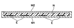
図7及び図8は、このようなインサート成形の一例を模式的に示す断面説明図である。
図7の例では、成形型M1の所定の部位に、所定の形状および面積を有する吸音材Eをインサートし固定した上で、成形型M2を閉じ合わせ、その後に材料樹脂Nを充填して成形を行うことにより、所定の片面の特定部位に所定形状および面積の吸音材Eを有する成形体が得られる。
【0041】
この場合、吸音材E以外の部分の表面領域は材料樹脂が凝固したスキン層で形成され、所定部位では吸音材Eで吸音効果を得る一方、その他の領域ではスキン層で遮音効果が得られる。
このような吸音材Eとスキン層とを好適に組み合わせることで、例えば、特に耳障りな特定周波数帯域の騒音を効果的に減衰させるように設定することができる。
【0042】
また、図8の例では、成形型M1の所定の部位に、所定の形状および面積を有する吸音材Eをインサート固定し、且つ、その他の領域に遮音シートGをインサート固定した上で、成形型M2を閉じ合わせ、その後に材料樹脂Nを充填して成形を行うことにより、所定の片面について、特定部位に所定形状および面積の吸音材Eを有し、且つ、その他の領域が遮音シートGで覆われた成形体が得られる。
【0043】
この場合、所定部位については吸音材Eで吸音効果を得る一方、その他の領域については遮音材Gによって高い遮音効果が得られる。
このような吸音材Eと遮音シートGとを好適に組み合わせることで、例えば、特に耳障りな特定周波数帯域の騒音を効果的に減衰させるように設定することができる。
【0044】
上記吸音材Eとしては、例えば、不織布,フェルト層,発泡もしくは未発泡のウレタン層,あるいは例えばナイロン樹脂製のカーペット層など、吸音性を有する種々のものが適用可能である。また、遮音シートGとしては、ある程度硬質の遮音性を有する合成樹脂製のシート材等を好適に用いることができる。
【0045】
尚、本発明は、以上の実施態様に限定されるものではなく、その要旨を逸脱しない範囲において、種々の改良あるいは設計上の変更が可能であることは言うまでもない。
【0048】
【発明の効果】
本願請求項1の発明によれば、フロアパネルが振動する際にはスペアタイヤ収納部を優先的に振動させ、この部分に騒音が集中し易くすることができ、その上で、スペアタイヤ収納部のトランクボードと対向する面に設けられた発泡層の露出した発泡部により、スペアタイヤ収納部とトランクボードとの間の空間内の騒音をより効果的に吸収することができる。すなわち、フロアパネルを樹脂製とすることで軽量化を達成し、しかも比較的低コストでより効率良く騒音低減を図ることができる。この場合、トランクボードの強度や剛性さらには見映え等に影響を及ぼすことなく吸音効果を高めることができる。
【0049】
また、本願請求項2の発明によれば、基本的には上記請求項1の発明と同様の効果を奏することができる。特に、フロアパネルが振動する際にスペアタイヤ収納部を優先的に振動させる上記フロアパネルの剛性設定を、スペアタイヤ収納部の少なくとも周辺部分にビード部を設けて行うことにより、該部分を補強しスペアタイヤ収納部を相対的に振動し易くすることができる。すなわち、簡単な構成で上記フロアパネルの剛性の設定を実現できる。
【0052】
また更に、本願請求項3の発明によれば、基本的には上記請求項1又は2の発明と同様の効果を奏することができる。特に、上記発泡部が露出した発泡層では、部分的に発泡部が露出しているだけであるので、かかる発泡層を設けたパネル材またはボード材の強度や剛性の低下を抑制できる。すなわち、フロアパネル又はトランクボードの強度・剛性の確保と吸音性の向上とを両立させることができるようになる。しかも、上記部分的に発泡部が露出した発泡層では、発泡部が露出した部分と発泡部が表皮層で覆われた部分とを、減衰対象として設定された周波数帯域に応じて組み合わせることにより、例えば、特に耳障りな特定周波数帯域の騒音を効果的に減衰させることができる。
【図面の簡単な説明】
【図1】 本発明の実施の形態に係る自動車のトランクルームを車体後方から見て概略的に示した説明図である。
【図2】 上記トランクルームのフロア構造の基本構成を模式的に示す断面説明図である。
【図3】 上記トランクルームのトランクボードの断面構造を模式的に示す断面説明図である。
【図4】 トランクボードとトランクフロアの組み合わせ状態の一例を模式的に示す断面説明図である。
【図5】 トランクフロアに形成したスペアタイヤ収納部をトランクボードで密閉する構造の一例を模式的に示す断面説明図である。
【図6】 スペアタイヤ収納部をトランクボードで密閉する構造の他の例を模式的に示す断面説明図である。
【図7】 吸音材をインサート材としたインサート成形の一例を模式的に示す断面説明図である。
【図8】 吸音材および遮音材をインサート材としたインサート成形の一例を模式的に示す断面説明図である。
【符号の説明】
B…トランクボード
Bp…発泡層
Bs…スキン層
C…ビード部
E…吸音材
F…トランクフロア(フロアパネル)
Fb…(トランクフロアの)ベース面
Fp…発泡層
Fs…スキン層
S…スペアタイヤ収納部
Sb…底面部
Sw…周縁壁部[0001]
BACKGROUND OF THE INVENTION
The present invention relates to a resin floor panel structure applied to a floor surface of a vehicle such as an automobile.
[0002]
[Prior art]
As is well known, the floor (floor surface) of a vehicle such as an automobile is conventionally composed of a steel panel floor panel.
However, in recent years, there has been a demand for further weight reduction of the vehicle body in order to further improve fuel efficiency, and as a part of meeting such demand, the floor panel itself is made of resin. Therefore, attempts have been made to reduce the weight. For example, Patent Document 1 discloses manufacturing an automobile floor by expansion molding.
[0003]
[Patent Document 1]
Japanese Patent Laid-Open No. 2001-10542
[Problems to be solved by the invention]
In this way, the floor panel itself can be made of resin instead of steel plate, thereby reducing the weight of the floor portion of the vehicle, but not only the strength and rigidity are reduced. The panel itself is lighter, and the resonance point becomes higher, and vibration and noise in the floor portion become more prominent, and there is also a problem that the noise reduction in the passenger compartment is hindered.
[0005]
It is conceivable to deal with this problem by increasing the thickness of the resin floor panel. However, increasing the thickness unnecessarily increases the weight and the manufacturing cost, and the floor panel is made of resin. There was a problem that the benefits could be lost.
[0006]
The present invention has been made in view of the above technical problem. When the floor panel is made of resin, noise in the floor portion is transmitted to the indoor side without causing an increase in weight with a relatively simple configuration. The basic purpose is to suppress the above.
[0009]
[Means for Solving the Problems]
Therefore, the resin floor panel structure according to the present gun onset Ming is a resin-made floor panel structure applied in a vehicle floor, the spare tire storage space and a floor panel made of resin formed integrally And a resin trunk board disposed so as to cover the floor panel, and when the floor panel vibrates, the rigidity of the floor panel is preferentially vibrated so that the spare tire storage portion vibrates. Is set, and a foam layer in which at least a part of the foam portion is exposed is provided on the surface of the spare tire storage portion facing the trunk board.
[0010]
In this case, the rigidity of the floor panel can be set by providing a bead portion at least in the peripheral portion of the spare tire storage portion.
[0012]
In the case above, part of the foaming layer in which the foam part is exposed, as partially foamed portion is exposed also rather good, the foam layer foamed part in this part batchwise is exposed, the foam part is exposed And the portion where the foamed portion is covered with the skin layer can be combined according to the frequency band set as the attenuation target.
[0013]
DETAILED DESCRIPTION OF THE INVENTION
DETAILED DESCRIPTION OF THE PREFERRED EMBODIMENTS Hereinafter, embodiments of the present invention will be described in detail with reference to the accompanying drawings, taking as an example a case where the embodiment is applied to a floor panel structure of a trunk room provided at the rear of a vehicle body such as an automobile.
FIG. 1 is an explanatory diagram schematically showing a trunk room of an automobile according to an embodiment of the present invention as viewed from the rear of the vehicle body. FIG. 2 is an explanatory cross-sectional view schematically showing the basic structure of the floor structure of the trunk room.
[0014]
As shown in these drawings, in the trunk room, a concave spare tire storage portion S is formed in the floor panel F (trunk floor) constituting the floor surface (floor) to store spare tires (not shown). Has been. The trunk floor F is integrally formed using a synthetic resin material instead of a conventional steel plate.
Although not specifically shown, both ends of the trunk floor F in the vehicle width direction are supported by a pair of left and right frame members (rear side frames) extending in the front-rear direction at the rear of the vehicle body. The front and rear end portions are respectively supported by a front frame and a rear end frame that extend in the vehicle width direction.
[0015]
A trunk board B is disposed above the trunk floor F so as to substantially cover the entire trunk floor F. This trunk board B is also integrally molded using a synthetic resin material.
A pair of left and right wheel houses Hw that covers the upper part of the left and right rear wheels (not shown) are formed in a relatively front portion of the left and right side walls Wc of the vehicle body in the trunk room.
[0016]
More preferably, the left and right side portions of the trunk board B are in airtight contact with the left and right side walls Wc of the vehicle body, and the airtightness of the space portion Af formed between the trunk board B and the trunk floor F is more preferable. The so-called road noise and tire noise from the lower part of the floor can be absorbed as much as possible in the space Af, and the noise can be suppressed from being transmitted to the indoor side.
[0017]
As the synthetic resin material for the trunk floor F and the trunk board B, for example, an FRP (fiber reinforced plastic) material based on polypropylene (PP) resin can be used. In addition to such resin materials, various known materials such as those in which a reinforcing material is blended with other resin materials such as nylon, ABS, PPO, and PBT are applicable. The reinforcing material is not limited to fiber reinforcing materials such as glass fibers and carbon fibers, and reinforcing materials such as talc and glass beads can be used.
[0018]
2, the spare tire storage portion S of the trunk floor F forms a flat reference surface of the trunk floor F from the bottom surface portion Sb on which the spare tire is placed and the peripheral edge portion of the bottom surface portion Sb. It is formed by the peripheral wall portion Sw rising up to the base surface Fb.
[0019]
FIG. 3 is a cross-sectional explanatory view schematically showing the cross-sectional structure of the trunk board B. As shown in FIG.
As shown in this figure, the trunk board B includes a foam layer Bp having a large number of porous voids (foamed portions) inside, and a skin layer (skin layer) Bs covering the upper and lower surface sides of the foam layer Bp. It is configured with.
[0020]
The foamed layer Bp can be obtained, for example, by adding a foaming agent to the material resin and foaming at the time of molding to form the foamed layer. Instead of using the foaming agent in this way, other methods such as a gas injection method or a critical foaming method can be applied.
The skin layer Bs is a so-called solid layer that is formed as a resin skin layer at a portion in contact with the mold surface of the mold, and is solidified without having a porous void due to foaming.
[0021]
In the present embodiment, at least a part of the skin layer Bs is removed only on the lower surface of the trunk board B (that is, the surface facing the trunk floor F), and the porous foamed portion is exposed in this portion. Yes.
The noise transmitted from the lower side of the trunk board B to the indoor side enters the foamed layer Bp from the portion where the solid skin layer Bs is removed, and part of the energy is directly absorbed by the porous foamed part Bp. Therefore, sound is absorbed very effectively.
[0022]
Even when the exposed portion of the foamed portion Bp is not provided and the entire surface is covered with the skin layer Bp, noise transmitted from the lower side of the trunk board B to the indoor side passes through the foamed layer Bp. However, as described above, at least a part of the skin layer Bs is removed and at least a part of the foam layer Bp is exposed, so that sound propagation is performed. The energy is directly absorbed by the foam layer Bp, and a higher sound absorption effect is obtained.
[0023]
Various methods are conceivable as a method for removing at least a part of the skin layer Bs. For example, after forming the trunk board B, a part of the skin layer Bs is mechanically peeled off by applying a cutting tool or the like. Thus, the foamed portion Bp at that portion can be exposed.
[0024]
As described above, by providing the foam layer Bp with the foam part exposed at least partially on the surface facing the trunk floor F of the trunk board B, the trunk floor F and the trunk board are formed by the exposed foam part Bp. The noise in the space Af between B can be absorbed more effectively. That is, by making the trunk floor F made of resin, weight reduction can be achieved, and noise can be reduced at a relatively low cost.
[0025]
In this case, the sound absorption effect can be enhanced without affecting the strength and rigidity of the trunk floor F that supports the spare tire, which is a heavy object, and the appearance. In addition, since the exposed foamed portion is provided only on the surface of the trunk board B facing the trunk floor F, the interior side of the trunk board B has a bad appearance due to dust adhering to the exposed portion. There is no effect.
[0026]
In particular, in the foamed layer Bp where the foamed part is exposed, the foamed part is only partially exposed, so that a decrease in strength and rigidity of the trunk board B provided with such a foamed layer can be suppressed. That is, it is possible to achieve both the strength and rigidity of the trunk board B and the improvement of sound absorption.
[0027]
In this case, in the foam layer Bp in which the foam part is partially exposed, more preferably, the part in which the foam part is exposed and the part in which the foam part is covered with the skin layer Bs are suitably combined, It is possible to set so as to effectively attenuate noise in a specific frequency band, for example, noise in a specific frequency band that is particularly annoying. That is, by using a combination according to the frequency band set as an attenuation target, it is possible to effectively attenuate noise in a particular frequency band that is particularly annoying.
[0028]
FIG. 4 is a cross-sectional explanatory view schematically showing an example of a combination state of the trunk board B and the trunk floor F. FIG.
In this example, the skin layers Bs and Fs are entirely removed on both the surface (lower surface) facing the trunk floor F of the trunk board B and the surface (upper surface) facing the trunk board B of the trunk floor F, Foamed layers Bp and Fp are exposed on the entire surfaces facing each other. Therefore, the noise in the space Af formed between the two is absorbed very effectively and is prevented from being transmitted to the indoor side.
[0029]
Further, a foamed layer Fp in which a foamed portion is exposed at least partially (the entire surface in the example of FIG. 4) may be provided on the surface (upper surface) of the trunk floor F facing the trunk board B. In this case, the noise in the space Af can be more effectively absorbed by the foamed portion exposed in the space Af formed between the floor panel and the trunk board. In particular, in this case, the sound absorbing effect can be enhanced without affecting the strength and rigidity of the trunk board B and the appearance.
[0030]
When absorbing the sound in the space, the smaller the space volume, the higher the energy density of the sound, so that effective sound absorption and attenuation can be performed. In addition, the higher the sealing property of the space, the more effective.
Therefore, for example, by configuring the spare tire storage portion S formed on the trunk floor F to be sealed with the trunk board B, the spare tire storage portion S having a relatively small space volume (compared to the space portion Af). It is possible to effectively absorb the noise inside.
[0031]
5 and 6 are cross-sectional explanatory views schematically illustrating a structure in which the spare tire storage portion S is sealed with the trunk board B. FIG.
In the example of FIG. 5, the trunk board B is provided with an annular projection Bk having a tapered surface Bj, and the tapered surface Bj of the projection Bk is fitted to the inner surface of the tapered peripheral wall portion Sw of the spare tire storage portion S. As a result, the spare tire storage portion S is sealed with the trunk board B. In addition, it is preferable that both the taper surface Bj of the projection Bk and the inner surface of the peripheral wall portion Sw fitted therewith are covered with the skin layer Bs.
[0032]
In the example of FIG. 6, the trunk board B is provided with an annular projecting portion Bg having a tapered surface Be, and the tapered surface Be of the projecting portion Bg is formed on the tapered peripheral wall portion Sw of the spare tire storage unit S. The spare tire storage portion S is sealed with the trunk board B by fitting the inner surface. In this case, a concave portion Bh is formed on the upper surface side of the protruding portion Bg, and the concave portion Bh can be used as an accessory case. In addition, it is preferable that both the taper surface Be of the protruding portion Bg and the inner surface of the peripheral wall portion Sw fitted therewith are covered with the skin layer Bs.
[0033]
As described above, in the structure in which the spare tire storage portion S is sealed with the trunk board B, the foam layer Bp in which the foam portion is exposed at least partially is provided only on the surface of the trunk board B facing the spare tire storage portion S. On the other hand, it is preferable to provide a foam layer Fp in which the foam part is covered with the skin layer Fs on the surface of the spare tire storage part S facing the trunk board B.
[0034]
That is, in this case, the exposed foamed portion of the foamed layer Bp provided on the surface of the trunk board B facing the spare tire storage portion S causes the space in the space between the spare tire storage portion S and the trunk board B to be increased. Noise can be absorbed more effectively. That is, weight reduction can be achieved by making the trunk floor F made of resin, and noise can be reduced at a relatively low cost.
[0035]
In this case, the surface of the spare tire storage portion S facing the trunk board B is provided with a foam layer Fs in which the foam portion is covered with the skin layer Fs. The sound absorption effect can be enhanced after ensuring the appearance and the like. Further, since the foam layer Bp where the foamed portion is exposed is provided only on the surface of the trunk board B facing the trunk floor F, there is no influence on the interior side of the trunk board B such as poor appearance.
[0036]
When absorbing the noise in the space between the spare tire storage part S and the trunk board B more effectively, when the trunk floor F vibrates, the spare tire storage part S vibrates preferentially, It is more effective to set the rigidity of the trunk floor F and provide the foam layer Bp with the foam part exposed at least partially on the surface of the spare tire storage part S facing the trunk board B.
[0037]
That is, when the trunk floor F vibrates, the spare tire storage portion S is preferentially vibrated, and noise can be easily concentrated on this portion. Then, the trunk board B of the spare tire storage portion S The exposed foamed portion of the foamed layer Fp provided on the opposing surface can more effectively absorb noise in the space between the spare tire storage portion S and the trunk board B.
[0038]
The rigidity of the trunk floor F as described above can be set by providing a bead portion at least in the peripheral portion of the spare tire storage portion S.
That is, by providing a bead portion at least in the peripheral portion of the spare tire storage portion S, the rigidity of the trunk floor F is reinforced with a simple configuration so that the portion is reinforced and the spare tire storage portion S is relatively easily vibrated. Can be set.
[0039]
In the above case, on the plate material (trunk board B or trunk floor F) side having the foam layer in which the foam part is partially exposed, the part where the foam part is exposed and the part where the foam part is covered with the skin layer, It is possible to set so as to effectively attenuate noise in a specific frequency band, for example, noise in a specific frequency band that is particularly annoying, in a suitable combination.
Such setting can be performed relatively easily and reliably by, for example, insert molding by suitably combining a sound absorbing material or a sound insulating material as an insert material.
[0040]
7 and 8 are cross-sectional explanatory views schematically showing an example of such insert molding.
In the example of FIG. 7, the sound absorbing material E having a predetermined shape and area is inserted and fixed in a predetermined portion of the mold M1, and then the mold M2 is closed, and then the material resin N is filled and molded. By performing the above, a molded body having the sound absorbing material E having a predetermined shape and area at a specific portion on a predetermined single side is obtained.
[0041]
In this case, the surface region of the portion other than the sound absorbing material E is formed by a skin layer in which the material resin is solidified, and the sound absorbing effect is obtained by the sound absorbing material E at a predetermined portion, while the sound insulating effect is obtained by the skin layer at other regions.
By suitably combining such a sound absorbing material E and the skin layer, for example, it can be set so as to effectively attenuate particularly annoying noise in a specific frequency band.
[0042]
In the example of FIG. 8, the sound absorbing material E having a predetermined shape and area is insert-fixed to a predetermined portion of the mold M1, and the sound insulating sheet G is insert-fixed to other regions, and then the mold M2 is closed, and then the material resin N is filled and molded, thereby having a sound absorbing material E having a predetermined shape and area at a specific portion on a predetermined one side, and the other region being a sound insulating sheet G. A covered molded body is obtained.
[0043]
In this case, the sound absorbing effect is obtained by the sound absorbing material E for the predetermined part, while the high sound insulating effect is obtained by the sound insulating material G for the other regions.
By suitably combining such a sound absorbing material E and the sound insulation sheet G, for example, it can be set so as to effectively attenuate particularly annoying noise in a specific frequency band.
[0044]
As the sound absorbing material E, various materials having sound absorbing properties such as a nonwoven fabric, a felt layer, a foamed or unfoamed urethane layer, or a carpet layer made of, for example, nylon resin can be applied. Moreover, as the sound insulation sheet G, a sheet material made of a synthetic resin having a sound insulation property that is somewhat hard can be suitably used.
[0045]
In addition, this invention is not limited to the above embodiment, It cannot be overemphasized that a various improvement or a design change is possible in the range which does not deviate from the summary.
[0048]
【The invention's effect】
According to the invention of the present gun according to claim 1, preferentially vibrates the spare tire storage portion when the floor panel is vibrated, can noise is easily concentrated on this portion, on the spare tire storage space The exposed foamed part of the foamed layer provided on the surface of the part facing the trunk board can more effectively absorb noise in the space between the spare tire storage part and the trunk board. That is, weight reduction can be achieved by making the floor panel made of resin, and noise can be more efficiently reduced at a relatively low cost. In this case, the sound absorbing effect can be enhanced without affecting the strength and rigidity of the trunk board and the appearance.
[0049]
Also, according to the present second aspect of the invention, basically it is possible to achieve the same effect as the invention described in claim 1. In particular, the rigidity of the floor panel, which preferentially vibrates the spare tire storage portion when the floor panel vibrates, is set by providing a bead portion at least in the peripheral portion of the spare tire storage portion, thereby reinforcing the portion. It is possible to relatively easily vibrate the spare tire storage portion. That is, the rigidity of the floor panel can be set with a simple configuration.
[0052]
Furthermore, according to the invention of claim 3 of the present application, basically the same effect as that of the invention of
[Brief description of the drawings]
FIG. 1 is an explanatory diagram schematically showing a trunk room of an automobile according to an embodiment of the present invention when viewed from the rear of a vehicle body.
FIG. 2 is a cross-sectional explanatory view schematically showing a basic configuration of a floor structure of the trunk room.
FIG. 3 is an explanatory cross-sectional view schematically showing a cross-sectional structure of a trunk board in the trunk room.
FIG. 4 is a cross-sectional explanatory view schematically showing an example of a combination state of a trunk board and a trunk floor.
FIG. 5 is an explanatory cross-sectional view schematically showing an example of a structure in which a spare tire storage portion formed on a trunk floor is sealed with a trunk board.
FIG. 6 is a cross-sectional explanatory view schematically showing another example of a structure in which a spare tire storage portion is sealed with a trunk board.
FIG. 7 is a cross-sectional explanatory view schematically showing an example of insert molding using a sound absorbing material as an insert material.
FIG. 8 is a cross-sectional explanatory view schematically showing an example of insert molding using a sound absorbing material and a sound insulating material as an insert material.
[Explanation of symbols]
B ... Trunk board Bp ... Foam layer Bs ... Skin layer C ... Bead part E ... Sound absorbing material F ... Trunk floor (floor panel)
Fb ... (Trunk floor) base surface Fp ... Foam layer Fs ... Skin layer S ... Spare tire storage part Sb ... Bottom face Sw ... Peripheral wall part
Claims (3)
上記フロアパネルが振動する際には上記スペアタイヤ収納部が優先的に振動するように、上記フロアパネルの剛性が設定されており、
上記スペアタイヤ収納部の上記トランクボードと対向する面に、少なくとも一部について発泡部が露出した発泡層を設けたことを特徴とする樹脂製フロアパネル構造。 A resin floor panel structure applied to the floor of a vehicle, the resin floor panel integrally formed with a spare tire storage portion, and a resin floor panel disposed so as to cover the floor panel With a trunk board,
When the floor panel vibrates, the rigidity of the floor panel is set so that the spare tire storage portion vibrates preferentially,
A resin floor panel structure, wherein a foam layer in which a foam part is exposed at least partially is provided on a surface of the spare tire storage part facing the trunk board.
上記フロアパネルの剛性の設定は、上記スペアタイヤ収納部の少なくとも周辺部分にビード部を設けて行われることを特徴とする樹脂製フロアパネル構造。 In the resin floor panel structure according to claim 1 ,
The resin floor panel structure is characterized in that the rigidity of the floor panel is set by providing a bead portion at least in the peripheral portion of the spare tire storage portion.
上記発泡部が露出した発泡層では、部分的に発泡部が露出しており、
上記部分的に発泡部が露出した発泡層では、発泡部が露出した部分と発泡部が表皮層で覆われた部分とが、減衰対象として設定された周波数帯域に応じて組み合わされることを特徴とする樹脂製フロアパネル構造。 In the resin floor panel structure according to claim 1 or 2 ,
In the foam layer where the foam part is exposed, the foam part is partially exposed,
In the foam layer in which the foam part is partially exposed, the part where the foam part is exposed and the part where the foam part is covered with the skin layer are combined according to the frequency band set as the attenuation target, Resin floor panel structure.
Priority Applications (4)
| Application Number | Priority Date | Filing Date | Title |
|---|---|---|---|
| JP2003120244A JP4167932B2 (en) | 2003-04-24 | 2003-04-24 | Resin floor panel structure |
| DE602004017928T DE602004017928D1 (en) | 2003-04-24 | 2004-04-21 | Base plate structure made of resin |
| EP04009451A EP1470992B1 (en) | 2003-04-24 | 2004-04-21 | Resin-made floor panel structure |
| US10/829,402 US6966592B2 (en) | 2003-04-24 | 2004-04-22 | Resin-made floor panel structure |
Applications Claiming Priority (1)
| Application Number | Priority Date | Filing Date | Title |
|---|---|---|---|
| JP2003120244A JP4167932B2 (en) | 2003-04-24 | 2003-04-24 | Resin floor panel structure |
Publications (2)
| Publication Number | Publication Date |
|---|---|
| JP2004322832A JP2004322832A (en) | 2004-11-18 |
| JP4167932B2 true JP4167932B2 (en) | 2008-10-22 |
Family
ID=32959664
Family Applications (1)
| Application Number | Title | Priority Date | Filing Date |
|---|---|---|---|
| JP2003120244A Expired - Fee Related JP4167932B2 (en) | 2003-04-24 | 2003-04-24 | Resin floor panel structure |
Country Status (4)
| Country | Link |
|---|---|
| US (1) | US6966592B2 (en) |
| EP (1) | EP1470992B1 (en) |
| JP (1) | JP4167932B2 (en) |
| DE (1) | DE602004017928D1 (en) |
Families Citing this family (8)
| Publication number | Priority date | Publication date | Assignee | Title |
|---|---|---|---|---|
| JP2007182025A (en) * | 2006-01-10 | 2007-07-19 | Mazda Motor Corp | Method for molding resin molded article |
| FR2897586B1 (en) * | 2006-02-23 | 2012-04-20 | Plastic Omnium Cie | PLASTIC AND ELASTOMER FLOOR OF MOTOR VEHICLE |
| CA2672821A1 (en) * | 2006-12-19 | 2008-06-26 | Dow Global Technologies Inc. | Floor module |
| JP5032854B2 (en) * | 2007-01-19 | 2012-09-26 | 本田技研工業株式会社 | Car body rear structure |
| US20090230729A1 (en) * | 2008-03-13 | 2009-09-17 | Kevin Lusk | Floor panel for a vehicle |
| EP2860086A4 (en) * | 2012-06-08 | 2016-01-20 | Honda Motor Co Ltd | Fibre-reinforced plastic cabin for vehicle |
| JP6341167B2 (en) * | 2015-09-07 | 2018-06-13 | トヨタ自動車株式会社 | Vehicle vibration suppression structure |
| US11447079B2 (en) * | 2018-01-05 | 2022-09-20 | Kasai Kogyo Co., Ltd. | Vehicle interior component and method for manufacturing vehicle interior component |
Family Cites Families (7)
| Publication number | Priority date | Publication date | Assignee | Title |
|---|---|---|---|---|
| NL8800641A (en) * | 1988-03-16 | 1989-10-16 | Stamicarbon | REAR FLOOR FOR AUTOMOTIVE. |
| US5421633A (en) * | 1993-06-21 | 1995-06-06 | Chrysler Corporation | Integrated utility/camper shell for a pick-up truck |
| JP3433064B2 (en) * | 1997-10-01 | 2003-08-04 | 本田技研工業株式会社 | Car floor structure |
| US5860687A (en) * | 1997-12-19 | 1999-01-19 | Chrysler Corporation | Vehicle spare tire storage system having stiffening plate |
| FR2792892B1 (en) * | 1999-04-30 | 2001-06-08 | Renault | SELF-SUPPORTING TRUNK MAT WITH INTEGRATED SPARE WHEEL COVER |
| JP2001010542A (en) | 1999-07-01 | 2001-01-16 | Idemitsu Petrochem Co Ltd | Automobile floor and its manufacture |
| US6739641B2 (en) * | 2001-12-04 | 2004-05-25 | The Dow Chemical Company | Composite spare wheel well |
-
2003
- 2003-04-24 JP JP2003120244A patent/JP4167932B2/en not_active Expired - Fee Related
-
2004
- 2004-04-21 EP EP04009451A patent/EP1470992B1/en not_active Expired - Lifetime
- 2004-04-21 DE DE602004017928T patent/DE602004017928D1/en not_active Expired - Fee Related
- 2004-04-22 US US10/829,402 patent/US6966592B2/en not_active Expired - Fee Related
Also Published As
| Publication number | Publication date |
|---|---|
| EP1470992A2 (en) | 2004-10-27 |
| EP1470992B1 (en) | 2008-11-26 |
| US6966592B2 (en) | 2005-11-22 |
| EP1470992A3 (en) | 2004-11-24 |
| DE602004017928D1 (en) | 2009-01-08 |
| JP2004322832A (en) | 2004-11-18 |
| US20040262936A1 (en) | 2004-12-30 |
Similar Documents
| Publication | Publication Date | Title |
|---|---|---|
| JP4205477B2 (en) | Resin floor panel structure | |
| US6971475B2 (en) | Vehicle trim components with selectively applied foam and methods of making same | |
| CZ294786B6 (en) | Passenger vehicle incorporating loudspeakers comprising panel-form acoustic radiating elements | |
| JP2008519704A (en) | Lightweight sound insulation coating for automobile body parts and method of manufacturing the same | |
| JP4167932B2 (en) | Resin floor panel structure | |
| WO2005084978A1 (en) | Sunvisor for automobile and sound absorbing structure of automobile running on road | |
| KR100946521B1 (en) | Carpet for vehicles and manufacture method thereof | |
| US7226113B2 (en) | Armrest insert and corresponding assembly for a vehicle | |
| JP3759997B2 (en) | Luggage box | |
| JP2006160177A (en) | Sound absorbing structure of automobile running on road | |
| JP2002046552A (en) | Panel vibration damping and sound insulating structure for automobile | |
| JP2007008417A (en) | Panel structure | |
| JP5096785B2 (en) | Sound absorbing structure | |
| JP4380213B2 (en) | Resin floor panel structure | |
| JPH01141145A (en) | Plastic knee protector and manufacture thereof | |
| JP2549339B2 (en) | Car seat core | |
| KR102319408B1 (en) | Engine cover and engine cover manufacturing method | |
| JP5593183B2 (en) | Vehicle noise reduction device | |
| JP3956102B2 (en) | Integral foam molded product and manufacturing method thereof | |
| JP2019051749A (en) | Silencer for vehicle, and method for manufacturing the same | |
| FR2900110A1 (en) | Sound insulating interior cladding for automobile floor, has sound insulator including visible layer, insert and intermediate foam layer with constricted region, thicker region and insulating cavity | |
| JPH0347946Y2 (en) | ||
| JP4590115B2 (en) | Shock absorption structure for vehicles | |
| JPH08113091A (en) | Rear parcel shelf for automobile | |
| JPS58194666A (en) | Soundproof construction in double wall |
Legal Events
| Date | Code | Title | Description |
|---|---|---|---|
| A621 | Written request for application examination |
Free format text: JAPANESE INTERMEDIATE CODE: A621 Effective date: 20051102 |
|
| A711 | Notification of change in applicant |
Free format text: JAPANESE INTERMEDIATE CODE: A712 Effective date: 20070625 |
|
| RD03 | Notification of appointment of power of attorney |
Free format text: JAPANESE INTERMEDIATE CODE: A7423 Effective date: 20070625 |
|
| A977 | Report on retrieval |
Free format text: JAPANESE INTERMEDIATE CODE: A971007 Effective date: 20080327 |
|
| A131 | Notification of reasons for refusal |
Free format text: JAPANESE INTERMEDIATE CODE: A131 Effective date: 20080422 |
|
| A521 | Request for written amendment filed |
Free format text: JAPANESE INTERMEDIATE CODE: A523 Effective date: 20080620 |
|
| TRDD | Decision of grant or rejection written | ||
| A01 | Written decision to grant a patent or to grant a registration (utility model) |
Free format text: JAPANESE INTERMEDIATE CODE: A01 Effective date: 20080715 |
|
| A01 | Written decision to grant a patent or to grant a registration (utility model) |
Free format text: JAPANESE INTERMEDIATE CODE: A01 |
|
| A61 | First payment of annual fees (during grant procedure) |
Free format text: JAPANESE INTERMEDIATE CODE: A61 Effective date: 20080804 |
|
| R150 | Certificate of patent or registration of utility model |
Ref document number: 4167932 Country of ref document: JP Free format text: JAPANESE INTERMEDIATE CODE: R150 Free format text: JAPANESE INTERMEDIATE CODE: R150 |
|
| FPAY | Renewal fee payment (event date is renewal date of database) |
Free format text: PAYMENT UNTIL: 20110808 Year of fee payment: 3 |
|
| FPAY | Renewal fee payment (event date is renewal date of database) |
Free format text: PAYMENT UNTIL: 20120808 Year of fee payment: 4 |
|
| R250 | Receipt of annual fees |
Free format text: JAPANESE INTERMEDIATE CODE: R250 |
|
| FPAY | Renewal fee payment (event date is renewal date of database) |
Free format text: PAYMENT UNTIL: 20130808 Year of fee payment: 5 |
|
| R250 | Receipt of annual fees |
Free format text: JAPANESE INTERMEDIATE CODE: R250 |
|
| R250 | Receipt of annual fees |
Free format text: JAPANESE INTERMEDIATE CODE: R250 |
|
| R250 | Receipt of annual fees |
Free format text: JAPANESE INTERMEDIATE CODE: R250 |
|
| R250 | Receipt of annual fees |
Free format text: JAPANESE INTERMEDIATE CODE: R250 |
|
| R250 | Receipt of annual fees |
Free format text: JAPANESE INTERMEDIATE CODE: R250 |
|
| R250 | Receipt of annual fees |
Free format text: JAPANESE INTERMEDIATE CODE: R250 |
|
| R250 | Receipt of annual fees |
Free format text: JAPANESE INTERMEDIATE CODE: R250 |
|
| R250 | Receipt of annual fees |
Free format text: JAPANESE INTERMEDIATE CODE: R250 |
|
| LAPS | Cancellation because of no payment of annual fees |